Embed Size (px)
Citation preview
Installation
Access to the
mobile viewer
Network Setting
Basic Layout
Rear View
This product supports Full HD that can connect to HDMI 1080P/60Hz monitors only.
Signal connection for POS and ATM is scheduled to be upgraded later.
Connecting the camera
If the IP camera provides the alarm I/O port or Audio I/O port, you can make alarm or audio connection. For more details, refer to the user manual of the IP camera.
J This product works only in a separate dedicated network to the IP cameras for stable recording performance. This is why this product does not operate at all if connected to the IP camera via the same network shared with the hub or router.
4 Channel
8 Channel
No. Item Description
a CAM1~CAM8Ethernet ports used for connecting the network camera video and power.
It allows supplying power to camera with PoE.
b WAN(UPLINK) Network port for connection to the Internet, router or hub.
c AUDIO IN Microphone connection port.
d ALARM OUT Alarm Out port.
e RS-485Communications port for connecting peripherals such as system keyboard.
f DC 12VNVR power input port. Connect to a 12V adaptor.
g RS-232CSignal connection port for POS and ATM.
Scheduled to be upgraded.
h ALARM IN Alarm input signal port.
i AUDIO OUT Port for speaker connection.
j HD MONITORPort for connecting a full HD(1920x1080) supported monitor. Use the HDMI cable to connect with a 1080p 60Hz monitor.
k VGA VGA video output terminal.
l eSATA Connection port for external SATA storage.
m LAN(DOWNLINK) Port for connecting the dedicated network device. (Do not share with other device.)
n DC 48VPower input port for the camera (PoE compliant). Connect to a 48V adaptor.
How to download and access the iOS-specific viewer
How to download and access the Android-specific viewer
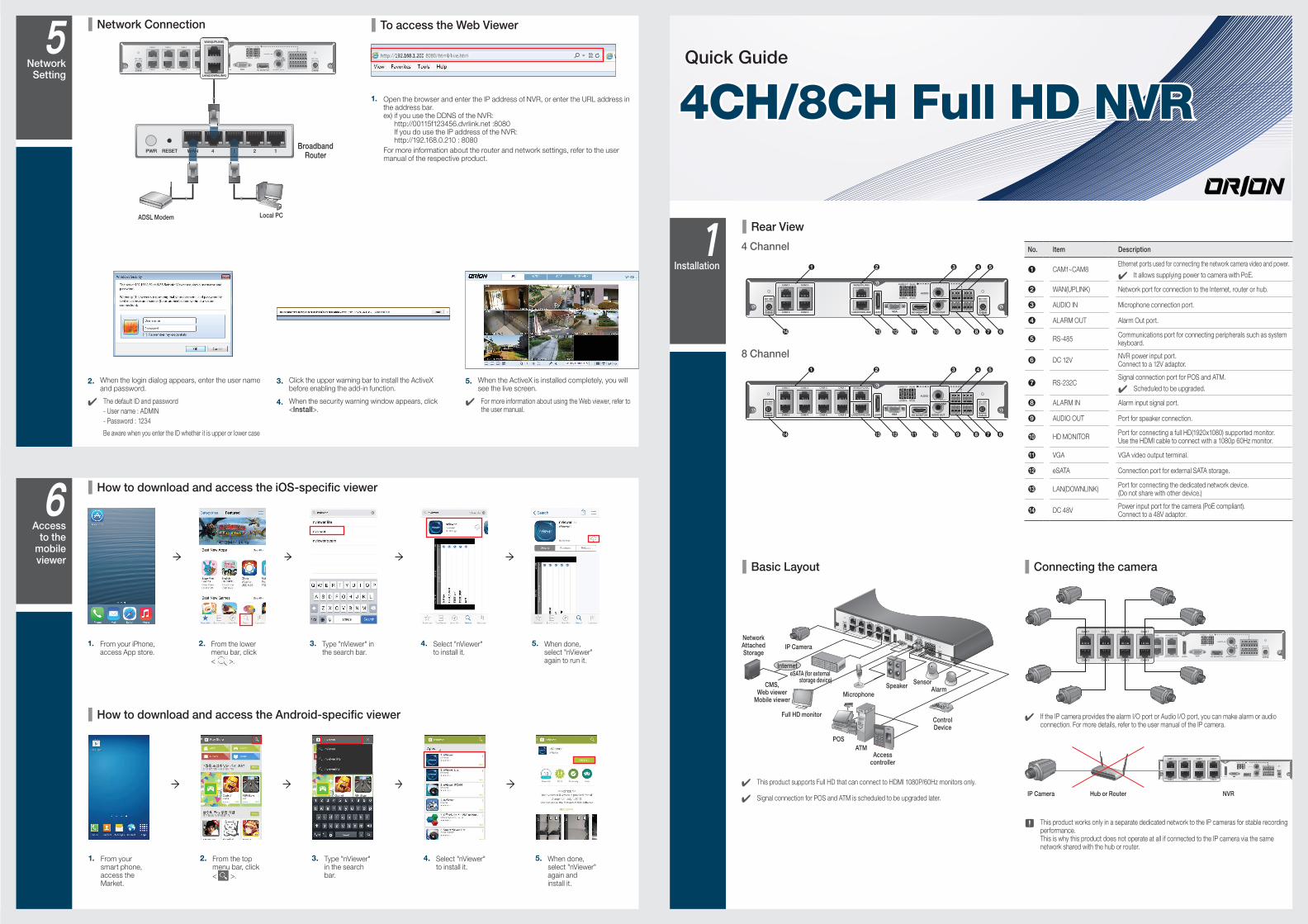
Network Connection To access the Web Viewer
2. When the login dialog appears, enter the user name and password.
The default ID and password
- User name : ADMIN
- Password : 1234
Be aware when you enter the ID whether it is upper or lower case
3. Click the upper warning bar to install the ActiveX before enabling the add-in function.
4. When the security warning window appears, click <Install>.
5. When the ActiveX is installed completely, you will see the live screen.
For more information about using the Web viewer, refer to the user manual.
1. Open the browser and enter the IP address of NVR, or enter the URL address in the address bar. ex) if you use the DDNS of the NVR:
http://00115f123456.dvrlink.net :8080 If you do use the IP address of the NVR: http://192.168.0.210 : 8080
For more information about the router and network settings, refer to the user manual of the respective product.
4CH/8CH Full HD NVR
Quick Guide
4WANRESETPWR 3 2 1WAN 3
WAN(UPLINK)
LAN(DOWNLINK) HD MONITOReSATA
ALARM OUT
ALARM IN
A1
NO
GN
DC
OM
A2
NC
GN
DG
ND
Tx
D +
Rx
D -
GN
DG
ND
RS-485
RS-232
AUDIO OUT
DC 12V
AUDIO IN
CAM 1
CAM 2
DC 48V
CAM 3
CAM 4
CAM 5
CAM 6
CAM 7
CAM 8
WAN(UPLINK)
LAN(DOWNLINK) HD MONITOReSATA
ALARM OUT
ALARM IN
A1
NO
GN
DC
OM
A2
NC
GN
DG
ND
Tx
D +
Rx
D -
GN
DG
ND
RS-485
RS-232
AUDIO OUT
DC 12V
AUDIO IN
CAM 1
CAM 2
DC 48V
CAM 3
CAM 4
CAM 5
CAM 6
CAM 7
CAM 8
WAN(UPLINK)
LAN(DOWNLINK)
ADSL Modem Local PC
Broadband Router
WAN(UPLINK)
LAN(DOWNLINK) HD MONITOReSATA
ALARM OUT
ALARM IN
A1
NO
GN
DC
OM
A2
NC
GN
DG
ND
Tx
D +
Rx
D -
GN
DG
ND
RS-485
RS-232
AUDIO OUT
DC 12V
AUDIO IN
CAM 1
CAM 2
DC 48V
CAM 3
CAM 4
a b c d e
g fhn m l k ij
WAN(UPLINK)
LAN(DOWNLINK) HD MONITOReSATA
ALARM OUT
ALARM IN
A1
NO
GN
DC
OM
A2
NC
GN
DG
ND
Tx
D +
Rx
D -
GN
DG
ND
RS-485
RS-232
AUDIO OUT
DC 12V
AUDIO IN
CAM 1
CAM 2
DC 48V
CAM 3
CAM 4
CAM 5
CAM 6
CAM 7
CAM 8
a b c d e
g fhn m l k ij
WAN(UPLINK)
LAN(DOWNLINK) HD MONITOReSATA
ALARM OUT
ALARM IN
A1
NO
GN
DC
OM
A2
NC
GN
DG
ND
Tx
D +
Rx
D -
GN
DG
ND
RS-485
RS-232
AUDIO OUT
DC 12V
AUDIO IN
CAM 1
CAM 2
DC 48V
CAM 3
CAM 4
CAM 5
CAM 6
CAM 7
CAM 8
WAN(UPLINK)
LAN(DOWNLINK) HD MONITOReSATA
ALARM OUT
ALARM IN
A1
NO
GN
DC
OM
A2
NC
GN
DG
ND
Tx
D +
Rx
D -
GN
DG
ND
RS-485
RS-232
AUDIO OUT
DC 12V
AUDIO IN
CAM 3
CAM 4
CAM 5
CAM 6
CAM 7
CAM 8
LAN(DOWNLINK)
CAM 1
CAM 2
CAM 3
CAM 4
CAM 5
CAM 6
CAM 7
CAM 8
IP Camera Hub or Router NVR
WAN(UPLINK)
LAN(DOWNLINK) HD MONITOReSATA
ALARM OUT
ALARM IN
A1
NO
GN
DC
OM
A2
NC
GN
DG
ND
Tx
D +
Rx
D -
GN
DG
ND
RS-485
RS-232
AUDIO OUT
DC 12V
AUDIO IN
CAM 1
CAM 2
DC 48V
CAM 3
CAM 4
CAM 5
CAM 6
CAM 7
CAM 8
WAN(UPLINK)
LAN(DOWNLINK) HD MONITOReSATA
ALARM OUT
ALARM IN
A1
NO
GN
DC
OM
A2
NC
GN
DG
ND
Tx
D +
Rx
D -
GN
DG
ND
RS-485
RS-232
AUDIO OUT
DC 12V
AUDIO IN
CAM 1
CAM 2
DC 48V
CAM 3
CAM 4
CAM 5
CAM 6
CAM 7
CAM 8
LAN(DOWNLIN
CAM 1
CAM 2
CAM 3
CAM 4
CAM 5
CAM 6
CAM 7
CAM 8
WAN(UPLINK)
LAN(DOWNLINK)
HD MONITOR
eSATA
ALARM OUT
ALARM IN
A1
NO
GN
DC
OM
A2
NC
GN
DG
ND
Tx
D +
Rx
D -
GN
DG
ND
RS-485
RS-232
AUDIO OUT
DC 12V
AUDIO IN
CAM 1
CAM 2
DC 48V
CAM 3
CAM 4
CAM 5
CAM 6
CAM 7
CAM 8
VGA
Control Device
POS
ATMAccess
controller
SensorAlarm
Speaker
Microphone
Full HD monitor
eSATA (for external storage device)
IP Camera
Internet
Network Attached Storage
CMS, Web viewer
Mobile viewer
1. From your iPhone, access App store.
2. From the lower menu bar, click
< >.
3. Type "nViewer" in the search bar.
4. Select "nViewer" to install it.
5. When done, select "nViewer" again to run it.
1. From your smart phone, access the Market.
2. From the top menu bar, click
< >.
3. Type "nViewer" in the search bar.
4. Select "nViewer" to install it.
5. When done, select "nViewer" again and install it.
Recording
Network Setting
Search
Item Description
MENUSelect one of the system setup, search and backup menu items before accessing it.
ADMIN Show the ID of the user who has currently logged in.
Edit the screen layout to show the status bar and timeline at all times or only when the mouse cursor hovers on the status bar/timeline.
Select a split mode.
Select Auto Sequence or Special Split Mode.
OSDOFF Display or hide the OSD menu on the screen.
Move to the PTZ screen. You can control the PTZ operations of a PTZ-compliant camera on the PTZ screen.
Move to the Digital Zoom.
Display the log list of the recent recording events.
Item Description
You can use the camera supporting the audio input to listen to the audio.
Select a camera to which the audio signal will be transferred from the connected microphone.
Start the panic recording.
Turns on if an event occurs. It does not turn on if no reaction to the event is yet defined. Click this to check the information of the event that occurred.
Check if network connection is made via an external PC or mobile device. Click this to view the details of the concurrent users and to check the network connection status.
OW
Show the disk space information. If you have set the disk overwrite mode, it will be displayed "OW" (Over Write) from the start point of the overwriting. Click this to view the details of the disk status.
01-01-201401:26:19 Display the current time and date.
Language Setting Date/Time Setting
Status Bar Besides the remote control buttons, you can also use the buttons on the bottom status bar to control the NVR.
1. Press [SETUP] on the remote control, or select <Menu> - <System Setup> from the status bar.
2. From <System Setup> - <Display>, select <OSD>.
3. Select a preferred language.
4. Click <Apply>.
1. Press [SETUP] on the remote control, or select <Menu> - <System Setup> from the status bar.
2. From <System Setup> - <System>, select <Date/Time>.
3. Specify the display format of the current time and date.
J As the existing data in the same time and date will be deleted if duplicates are found, back up the existing data for later use.
4. Click <Apply>.
Item Description
Channel No Display the number of the current channel.
Play Start playing the video of the selected channel from the specified time.
Zoom Zoom the video of the selected channel.
Snapshot Capture
Capture the current live video and save it in the .jpeg format.
Then, you can save the captured video in the HDD or export it to an external USB memory device.
Audio ON/OFF Turn on or off the audio signal of the selected channel.
Microphone On/Off Turn on or off the microphone signal of the selected channel.
ONE PUSHAutomatically adjusts the focus, within the camera s focus range. It is available only if supported by the connected camera.
Item Description
Timeline Date 01-01-2014Display the date of the current timeline. Click this to select a desired date of the timeline.
Zoom in/out the timeline
Expand or collapse the timeline.
Navigation through Timeline
Move to the previous or next point of time in the timeline. You can also use the mouse wheel to navigate through the timeline.
Timeline Bar
Represent the recorded data. The color of each bar indicates:
~ Green : Continuous Recording
~ Red : Alarm Recording
~ Blue : Motion Recording
~ Yellow: Panic Recording
Double-click the timeline to move to the Playback mode. Drag and drop it to make backup or event search for the specified area.
Video Window Quick Menu
Status Bar
Timeline
Getting Started
Automatic Recording Setting
1. Press [MENU] on the remote control, and use the direction buttons to select <RECORD SETUP> and press [ENTER]. Alternatively, you can select <MENU> - <RECORD SETUP> from the status bar.
2. Set <RECORD SETUP MODE> to <AUTO CONFIGURATION>.
3. Select "Automatic Record Configuration Mode".
CONTINUOUS RECORD : Records always regardless of events. - LONG DURATION BUT LOW QUAILTY : Recording will proceed in the low quality at all times. As this option will always make recording in the low quality, the recording period is the longest compared to the other record modes.
Time Search
1. From the <SEARCH> menu, select <TIME SEARCH>.
2. Specify the search date and time from the calendar in the left corner of the screen.
3. You can identify the type of the recording data by the color in the bar.
Yellow Green (Pre recording) : The pre-recording is performed on the recording data after you set the <PRE RECORDING TIME> from <OPERATION MODE>.
Green (Continuous) : The continuous recording is performed on the recording data.
Red (Alarm) : The alarm event recording is performed on the recording data.
Blue (Motion) : The motion event recording is performed on the recording data.
Yellow (Panic) : The panic manual recording is performed on the recording data.
4. Click to move to a desired start time in the time bar, or use the buttons at the bottom of the status bar to make search.
5. Select an item to play and click <PLAY>.
J Click to move to a desired time, or simply double-click a desired time in the time bar to play the video data on that time.
For details on thumbnail search and event search, refer to the user manual.
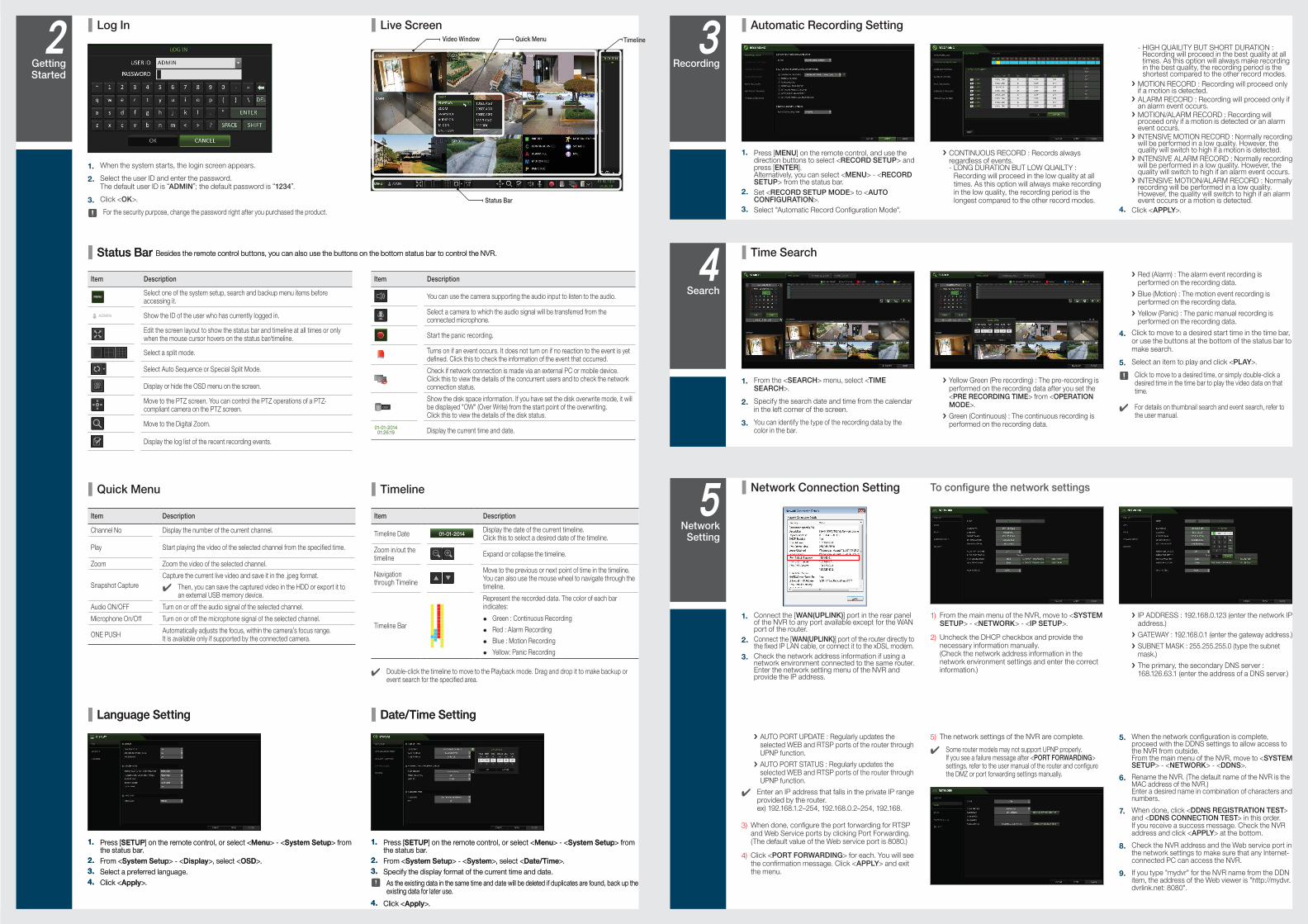
Network Connection Setting To configure the network settings
1. Connect the [WAN(UPLINK)] port in the rear panel of the NVR to any port available except for the WAN port of the router.
2. Connect the [WAN(UPLINK)] port of the router directly to the fixed IP LAN cable, or connect it to the xDSL modem.
3. Check the network address information if using a network environment connected to the same router.Enter the network setting menu of the NVR and provide the IP address.
1) From the main menu of the NVR, move to <SYSTEM SETUP> - <NETWORK> - <IP SETUP>.
2) Uncheck the DHCP checkbox and provide the necessary information manually. (Check the network address information in the network environment settings and enter the correct information.)
IP ADDRESS : 192.168.0.123 (enter the network IP address.)
GATEWAY : 192.168.0.1 (enter the gateway address.)
SUBNET MASK : 255.255.255.0 (type the subnet mask.)
The primary, the secondary DNS server : 168.126.63.1 (enter the address of a DNS server.)
- HIGH QUAILITY BUT SHORT DURATION : Recording will proceed in the best quality at all times. As this option will always make recording in the best quality, the recording period is the shortest compared to the other record modes.
MOTION RECORD : Recording will proceed only if a motion is detected.
ALARM RECORD : Recording will proceed only if an alarm event occurs.
MOTION/ALARM RECORD : Recording will proceed only if a motion is detected or an alarm event occurs.
INTENSIVE MOTION RECORD : Normally recording will be performed in a low quality. However, the quality will switch to high if a motion is detected.
INTENSIVE ALARM RECORD : Normally recording will be performed in a low quality. However, the quality will switch to high if an alarm event occurs.
INTENSIVE MOTION/ALARM RECORD : Normally recording will be performed in a low quality. However, the quality will switch to high if an alarm event occurs or a motion is detected.
4. Click <APPLY>.
AUTO PORT UPDATE : Regularly updates the selected WEB and RTSP ports of the router through UPNP function.
AUTO PORT STATUS : Regularly updates the selected WEB and RTSP ports of the router through UPNP function.
Enter an IP address that falls in the private IP range provided by the router. ex) 192.168.1.2~254, 192.168.0.2~254, 192.168.
3) When done, configure the port forwarding for RTSP and Web Service ports by clicking Port Forwarding. (The default value of the Web service port is 8080.)
4) Click <PORT FORWARDING> for each. You will see the confirmation message. Click <APPLY> and exit the menu.
5) The network settings of the NVR are complete.
Some router models may not support UPNP properly. If you see a failure message after <PORT FORWARDING> settings, refer to the user manual of the router and configure the DMZ or port forwarding settings manually.
5. When the network configuration is complete, proceed with the DDNS settings to allow access to the NVR from outside. From the main menu of the NVR, move to <SYSTEM SETUP> - <NETWORK> - <DDNS>.
6. Rename the NVR. (The default name of the NVR is the MAC address of the NVR.) Enter a desired name in combination of characters and numbers.
7. When done, click <DDNS REGISTRATION TEST> and <DDNS CONNECTION TEST> in this order. If you receive a success message. Check the NVR address and click <APPLY> at the bottom.
8. Check the NVR address and the Web service port in the network settings to make sure that any Internet-connected PC can access the NVR.
9. If you type "mydvr" for the NVR name from the DDN item, the address of the Web viewer is "http://mydvr.dvrlink.net: 8080".
Language Setting Date/Time Setting
Status Bar Besides the remote control buttons, you can also use the buttons on the bottom status bar to control the NVR.
1. Press [SETUP] on the remote control, or select <Menu> - <System Setup> from the status bar.
2. From <System Setup> - <Display>, select <OSD>.
3. Select a preferred language.
4. Click <Apply>.
1. Press [SETUP] on the remote control, or select <Menu> - <System Setup> from the status bar.
2. From <System Setup> - <System>, select <Date/Time>.
3. Specify the display format of the current time and date.
J As the existing data in the same time and date will be deleted if duplicates are found, back up the existing data for later use.
4. Click <Apply>.
TimelineQuick Menu
Log In Live Screen
1. When the system starts, the login screen appears.
2. Select the user ID and enter the password. The default user ID is ADMIN ; the default password is 1234 .
3. Click <OK>.
J For the security purpose, change the password right after you purchased the product.