Embed Size (px)
Citation preview
Page 108.16.16
1YEARlimited
WARRANTY
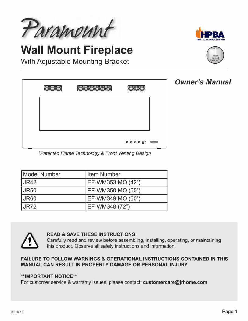
Wall Mount FireplaceWith Adjustable Mounting Bracket
Owner’s Manual
Model Number Item NumberJR42 EF-WM353 MO (42”)JR50 EF-WM350 MO (50”)JR60 EF-WM349 MO (60”)JR72 EF-WM348 (72”)
*Patented Flame Technology & Front Venting Design
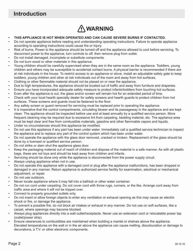
READ & SAVE THESE INSTRUCTIONSCarefully read and review before assembling, installing, operating, or maintaining this product. Observe all safety instructions and information.
FAILURE TO FOLLOW WARNINGS & OPERATIONAL INSTRUCTIONS CONTAINED IN THIS MANUAL CAN RESULT IN PROPERTY DAMAGE OR PERSONAL INJURY
**IMPORTANT NOTICE**For customer service & warranty issues, please contact: [email protected]
Page 2 08.16.16
Introduction
WARNING• THIS APPLIANCE IS HOT WHEN OPERATED AND CAN CAUSE SEVERE BURNS IF CONTACTED.• Do not operate appliance before reading and understanding operating instructions. Failure to operate appliance
accordingtooperatinginstructionscouldcausefireorinjury.• Risk of burns. Power to the appliance should be turned off and the appliance allowed to cool before servicing. To
disconnect power to the appliance, turn controls to off, then remove plug from outlet.• Do not install damaged, incomplete or substitute components.• Do not burn wood or other materials in this appliance.• Young children should be carefully supervised when they are in the same room as the appliance. Toddlers, young
children and others may be susceptible to accidental contact burns. A physical barrier is recommended if there are at risk individuals in the house. To restrict access to an appliance or stove, install an adjustable safety gate to keep toddlers, young children and other at risk individuals out of the room and away from hot surfaces.
• Clothingorotherflammablematerialshouldnotbeplacedonorneartheappliance.• Duetohightemperatures,theapplianceshouldbelocatedoutoftrafficandawayfromfurnitureanddraperies.• Ensure you have incorporated adequate safety measure to protect infants/toddlers from touching hot surfaces.• Even after the appliance is out, the glass and/or screen will remain hot for an extended period of time.• Check with your local hearth specialty dealer for safety screens and hearth guards to protect children from hot
surfaces.Thesescreensandguardsmustbefastenedtothefloor.• Any safety screen or guard removed for servicing must be replaced prior to operating the appliance.• It is imperative that the control compartments, circulating blower and its passageway in the appliance and are kept
clean.Theapplianceshouldbeinspectedbeforeuseandatleastannuallybyaqualifiedserviceperson.Morefrequent cleaning may be required due to excessive lint from carpeting, bedding material, etc. The appliance area mustbekeptclearandfreefromcombustiblematerials,gasolineandotherflammablevaporsandliquids.
• Undernocircumstancesshouldthisappliancebemodified.• Donotusethisapplianceifanyparthasbeenunderwater.Immediatelycallaqualifiedservicetechniciantoinspect
the appliance and to replace any part of the control system which has been under water.• Do not operate the appliance with the glass door removed, cracked or broken. Replacement of the glass should be
donebyalicensedorqualifiedserviceperson.• Do not strike or slam shut the appliance glass door.• Keep the packaging material out of reach of children and dispose of the material in a safe manner. As with all plastic
bags, these are not toys and should be kept away from children and infants.• Servicing should be done only while the appliance is disconnected from the power supply circuit.• Always unplug appliance when not in use.• Do not operate this appliance with a damaged cord or plug after the appliance malfunctions, has been dropped or
damaged in any manner. Return appliance to authorized service facility for examination, electrical or mechanical adjustment, or repair.
• Do not use outdoors.• Never locate appliance where it may fall into a bathtub or other water container.• Do not run cord under carpeting. Do not cover cord with throw rugs, runners, or the like. Arrange cord away from
trafficareaandwhereitwillnotbetrippedover.• Connect to properly grounded outlets only.• Do not insert or allow foreign objects to enter any ventilation or exhaust opening as this may cause an electric
shockorfire,ordamagetheappliance.• Topreventapossiblefire,donotblockairintakesorexhaustinanymanner.Donotuseonsoftsurfaces,likea
carpet, where openings may become blocked.• Always plug appliances directly into a wall outlet/receptacle. Never use an extension cord or relocatable power tap
(outlet/power strip).• Ensure clearances to combustibles are maintained when building a mantel or shelves above the appliance.
Elevated temperatures on the wall or in the air above the appliance can cause melting, discolouration or damage to decorations, a T.V. or other electronic components.

Page 308.16.16
Dimensions
Listing Approvals
FRONT VIEW
TOP VIEW
SIDE VIEW
ThisappliancehasbeentestedinaccordancewiththeCSAStandardsforfixedandlocation-dedicatedelectric room appliances in the United States and Canada. If you need assistance during installation, please contact your local dealer.
NOTE: This appliance must be electrically wired and grounded in accordance with local codes or, in the absence of local codes, with National Electric Code ANSI/NFPA 70-latest edition in the United States or the Canadian Electric Code, CSA C22.1 in Canada.
PRODUCT DIMENSIONS CARTON DIMENSIONS
Item No. A B C D E F G Width x Depth x Height
EF-WM353 MO 42” 20” 4.2” 18.8” 36.10” 9.72” 31.97” 49” x 10.24” x 25.59”
EF-WM350 MO 50” 20” 4.2” 18.8” 44.10” 9.72” 39.72” 56.89” x 10.24” x 25.59”
EF-WM349 MO 60” 20” 4.2” 18.8” 54.10” 9.72” 50” 66.93” x 10.24” x 25.59”
EF-WM348 72” 23.25” 4.2” 20.27” 66.10” 10.24” 60” 74.80” x 6.5” x 25.28”
Item No. Net Weight Gross WeightEF-WM353 MO 22 KGS 28 KGSEF-WM350 MO 26 KGS 33.5 KGSEF-WM349 MO 31 KGS 39 KGS
EF-WM 348 40 KGS 48 KGS
Description Electric FireplaceType 3 Way Mounting Wall Mount
Voltage 120V ACWatts MAX 1500WAmps 15 AMP Grounded Circuit
A
E
GF
B D
C
Page 4 08.16.16
General Instructions
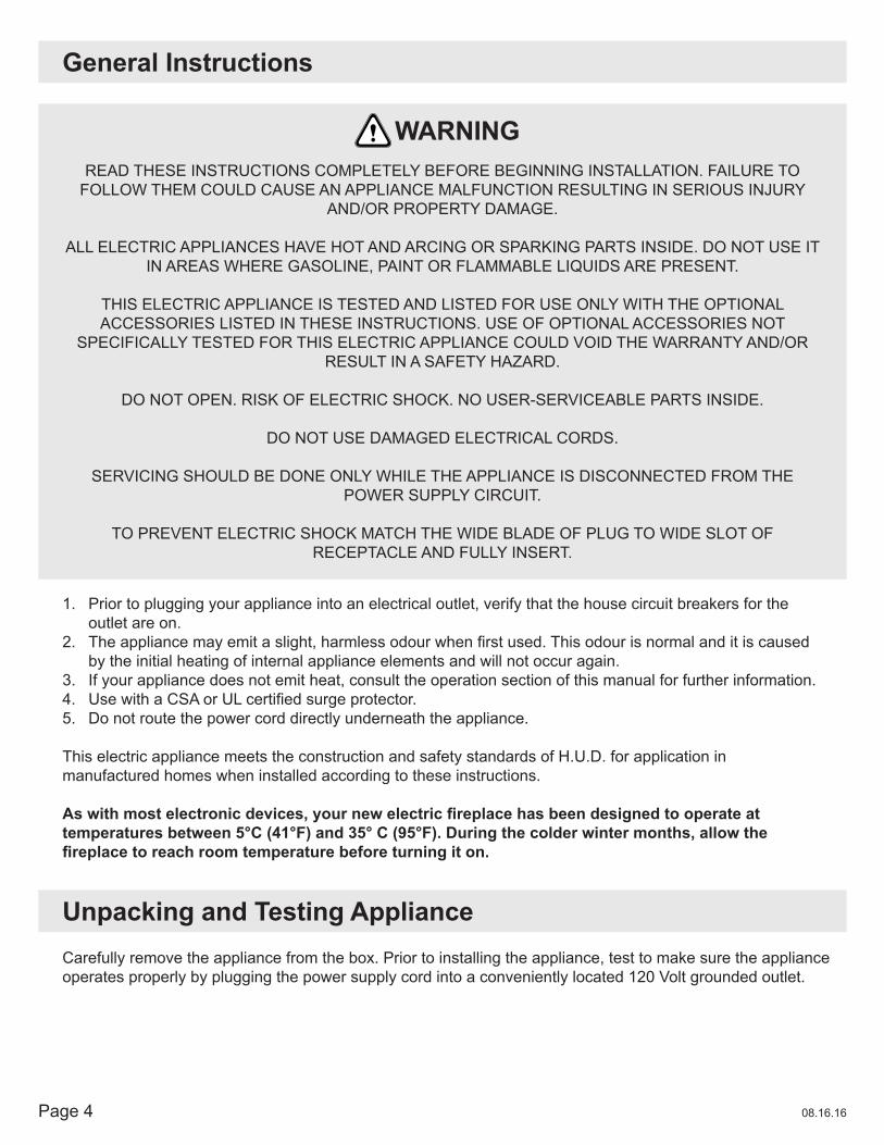
READ THESE INSTRUCTIONS COMPLETELY BEFORE BEGINNING INSTALLATION. FAILURE TO FOLLOW THEM COULD CAUSE AN APPLIANCE MALFUNCTION RESULTING IN SERIOUS INJURY
AND/OR PROPERTY DAMAGE.
ALL ELECTRIC APPLIANCES HAVE HOT AND ARCING OR SPARKING PARTS INSIDE. DO NOT USE IT IN AREAS WHERE GASOLINE, PAINT OR FLAMMABLE LIQUIDS ARE PRESENT.
THIS ELECTRIC APPLIANCE IS TESTED AND LISTED FOR USE ONLY WITH THE OPTIONAL ACCESSORIES LISTED IN THESE INSTRUCTIONS. USE OF OPTIONAL ACCESSORIES NOT
SPECIFICALLY TESTED FOR THIS ELECTRIC APPLIANCE COULD VOID THE WARRANTY AND/OR RESULT IN A SAFETY HAZARD.
DO NOT OPEN. RISK OF ELECTRIC SHOCK. NO USER-SERVICEABLE PARTS INSIDE.
DO NOT USE DAMAGED ELECTRICAL CORDS.
SERVICING SHOULD BE DONE ONLY WHILE THE APPLIANCE IS DISCONNECTED FROM THE POWER SUPPLY CIRCUIT.
TO PREVENT ELECTRIC SHOCK MATCH THE WIDE BLADE OF PLUG TO WIDE SLOT OF RECEPTACLE AND FULLY INSERT.
1. Prior to plugging your appliance into an electrical outlet, verify that the house circuit breakers for the outlet are on.
2. Theappliancemayemitaslight,harmlessodourwhenfirstused.Thisodourisnormalanditiscausedby the initial heating of internal appliance elements and will not occur again.
3. If your appliance does not emit heat, consult the operation section of this manual for further information.4. UsewithaCSAorULcertifiedsurgeprotector.5. Do not route the power cord directly underneath the appliance.
This electric appliance meets the construction and safety standards of H.U.D. for application in manufactured homes when installed according to these instructions.
Aswithmostelectronicdevices,yournewelectricfireplacehasbeendesignedtooperateattemperatures between 5°C (41°F) and 35° C (95°F). During the colder winter months, allow the fireplacetoreachroomtemperaturebeforeturningiton.
WARNING
Unpacking and Testing ApplianceCarefully remove the appliance from the box. Prior to installing the appliance, test to make sure the applianceoperates properly by plugging the power supply cord into a conveniently located 120 Volt grounded outlet.

Page 508.16.16
EF-WM353 MO (42”) x2EF-WM350 MO (50”) x2EF-WM349 MO (60”) x2
EF-WM348 (72”) x2
EF-WM353 MO (42”) x2EF-WM350 MO (50”) x2EF-WM349 MO (60”) x2
EF-WM348 (72”) x2
EF-WM353 MO (42”) x2EF-WM350 MO (50”) x2EF-WM349 MO (60”) x2
EF-WM348 (72”) x2
EF-WM353 MO (42”) x1EF-WM350 MO (50”) x1EF-WM349 MO (60”) x1
EF-WM348 (72”) x1
EF-WM353 MO (42”) x1EF-WM350 MO (50”) x1EF-WM349 MO (60”) x1
EF-WM348 (72”) x1
EF-WM353 MO (42”) x8EF-WM350 MO (50”) x8EF-WM349 MO (60”) x26
EF-WM348 (72”) x32
EF-WM353 MO (42”) x1EF-WM350 MO (50”) x1EF-WM349 MO (60”) x1
EF-WM348 (72”) x1
EF-WM353 MO (42”) x9EF-WM350 MO (50”) x13EF-WM349 MO (60”) x13
EF-WM348 (72”) x16
EF-WM353 MO (42”) x9EF-WM350 MO (50”) x13EF-WM349 MO (60”) x13
EF-WM348 (72”) x16
EF-WM353 MO (42”) x1EF-WM350 MO (50”) x1EF-WM349 MO (60”) x1
EF-WM348 (72”) x1
EF-WM353 MO (42”) x4EF-WM350 MO (50”) x4EF-WM349 MO (60”) x4
EF-WM348 (72”) x4
EF-WM349 MO (60”) x6EF-WM348 (72”) x8
EF-WM349 MO (60”) x6EF-WM348 (72”) x8
F- Drywall AnchorsD- Mounting Bracket
L- Cord Cover
E- Wood Screws
A- Fireplace B- Side Brackets
OPTIONAL
For kit of OPTIONAL parts J, K, L
(Item No: EF-WC)contact:
1-800-561-5550
OPTIONALOPTIONAL
C1 - Top/Bottom Brackets C2 - Top/Bottom Brackets
G- ST4x12 Metal Screws
I- Crystals
J- Cord Corner K- Cord Corner
H- Remote Control
Hardware Parts List
Page 6 08.16.16
Locating Appliance
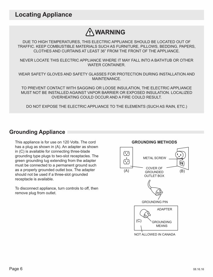
DUE TO HIGH TEMPERATURES, THIS ELECTRIC APPLIANCE SHOULD BE LOCATED OUT OFTRAFFIC. KEEP COMBUSTIBLE MATERIALS SUCH AS FURNITURE, PILLOWS, BEDDING, PAPERS,
CLOTHES AND CURTAINS AT LEAST 36” FROM THE FRONT OF THE APPLIANCE.
NEVER LOCATE THIS ELECTRIC APPLIANCE WHERE IT MAY FALL INTO A BATHTUB OR OTHER WATER CONTAINER.
WEAR SAFETY GLOVES AND SAFETY GLASSES FOR PROTECTION DURING INSTALLATION ANDMAINTENANCE.
TO PREVENT CONTACT WITH SAGGING OR LOOSE INSULATION, THE ELECTRIC APPLIANCEMUST NOT BE INSTALLED AGAINST VAPOR BARRIER OR EXPOSED INSULATION. LOCALIZED
OVERHEATING COULD OCCUR AND A FIRE COULD RESULT.
DO NOT EXPOSE THE ELECTRIC APPLIANCE TO THE ELEMENTS (SUCH AS RAIN, ETC.)
WARNING
This appliance is for use on 120 Volts. The cord has a plug as shown in (A). An adapter as shown in (C) is available for connecting three-blade grounding type plugs to two-slot receptacles. The green grounding lug extending from the adapter must be connected to a permanent ground such as a properly grounded outlet box. The adapter should not be used if a three-slot grounded receptacle is available.
To disconnect appliance, turn controls to off, then remove plug from outlet.
METAL SCREW
(A)
NOT ALLOWED IN CANADA
GROUNDINGMEANS
ADAPTER
GROUNDING PIN
COVER OF GROUNDEDOUTLET BOX
(C)
(B)
GROUNDING METHODS
Grounding Appliance
Page 708.16.16
Installation
Minimum Clearance to Combustibles
Minimum Mantel Clearances
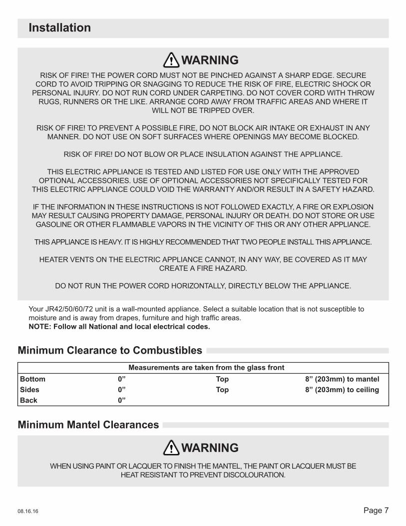
RISK OF FIRE! THE POWER CORD MUST NOT BE PINCHED AGAINST A SHARP EDGE. SECURE CORD TO AVOID TRIPPING OR SNAGGING TO REDUCE THE RISK OF FIRE, ELECTRIC SHOCK OR
PERSONAL INJURY. DO NOT RUN CORD UNDER CARPETING. DO NOT COVER CORD WITH THROW RUGS, RUNNERS OR THE LIKE. ARRANGE CORD AWAY FROM TRAFFIC AREAS AND WHERE IT
WILL NOT BE TRIPPED OVER.
RISK OF FIRE! TO PREVENT A POSSIBLE FIRE, DO NOT BLOCK AIR INTAKE OR EXHAUST IN ANY MANNER. DO NOT USE ON SOFT SURFACES WHERE OPENINGS MAY BECOME BLOCKED.
RISK OF FIRE! DO NOT BLOW OR PLACE INSULATION AGAINST THE APPLIANCE.
THIS ELECTRIC APPLIANCE IS TESTED AND LISTED FOR USE ONLY WITH THE APPROVED OPTIONAL ACCESSORIES. USE OF OPTIONAL ACCESSORIES NOT SPECIFICALLY TESTED FOR
THIS ELECTRIC APPLIANCE COULD VOID THE WARRANTY AND/OR RESULT IN A SAFETY HAZARD.
IF THE INFORMATION IN THESE INSTRUCTIONS IS NOT FOLLOWED EXACTLY, A FIRE OR EXPLOSION MAY RESULT CAUSING PROPERTY DAMAGE, PERSONAL INJURY OR DEATH. DO NOT STORE OR USE GASOLINE OR OTHER FLAMMABLE VAPORS IN THE VICINITY OF THIS OR ANY OTHER APPLIANCE.
THIS APPLIANCE IS HEAVY. IT IS HIGHLY RECOMMENDED THAT TWO PEOPLE INSTALL THIS APPLIANCE.
HEATER VENTS ON THE ELECTRIC APPLIANCE CANNOT, IN ANY WAY, BE COVERED AS IT MAY CREATE A FIRE HAZARD.
DO NOT RUN THE POWER CORD HORIZONTALLY, DIRECTLY BELOW THE APPLIANCE.
WHEN USING PAINT OR LACQUER TO FINISH THE MANTEL, THE PAINT OR LACQUER MUST BEHEAT RESISTANT TO PREVENT DISCOLOURATION.
WARNING
WARNING
Your JR42/50/60/72 unit is a wall-mounted appliance. Select a suitable location that is not susceptible to moistureandisawayfromdrapes,furnitureandhightrafficareas.NOTE: Follow all National and local electrical codes.
BottomSidesBack
0”0”0”
TopTop
Measurements are taken from the glass front8” (203mm) to mantel8” (203mm) to ceiling
Page 8 08.16.16
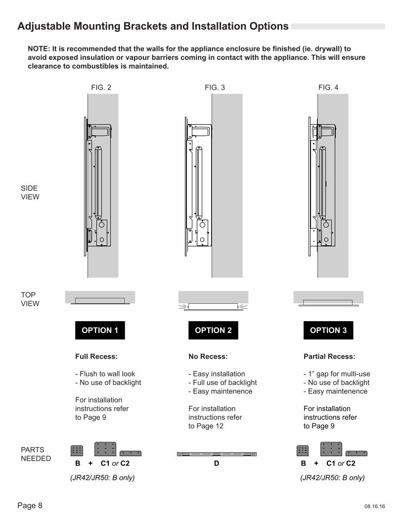
No Recess:
- Easy installation- Full use of backlight- Easy maintenence
For installation instructions refer to Page 12
Adjustable Mounting Brackets and Installation Options
Full Recess:
- Flush to wall look- No use of backlight
For installation instructions refer to Page 9
Partial Recess:
- 1” gap for multi-use- No use of backlight- Easy maintenence
For installation instructions refer to Page 9
FIG. 2
SIDEVIEW
TOPVIEW
PARTS NEEDED
FIG. 3 FIG. 4
NOTE:Itisrecommendedthatthewallsfortheapplianceenclosurebefinished(ie.drywall)toavoid exposed insulation or vapour barriers coming in contact with the appliance. This will ensure clearance to combustibles is maintained.
OPTION 1 OPTION 2 OPTION 3
B + C1 or C2
(JR42/JR50: B only) (JR42/JR50: B only)
B + C1 or C2D

Page 908.16.16
Option 1: Recessing the Appliance Flush into the Wall
Duetothemanydifferentfinishmaterialsusedonwalls,itishighlyrecommendedthatyouconsultyourlocalbuilder before you install this appliance in the wall.
Select a location that is not prone to moisture and is located at least 36” (914mm) away from combustible materials such as curtain drapes, furniture, bedding, paper etc.
C1 or C2
B
1. Measure the appliance and create a rough in with electrical.
2. Remove the front glass (refer to Page 15 for instructions).
3. Remove the LED back lights (refer to Page 16 for instructions).
4. Holdtheapplianceuptoensureitwillfitintotheframing.
5. To fully recess the appliance into the wall: A. Position and screw the side Builder’s brackets (shown in grey on Page 10) to the set of holes closest to the front glass as in Figure 2 on Page 8. B. Use 8-24 screws (provided) to lock appliance into wall from the side facing out. C. Install the media and reinstall the glass front.
6. To partially recess the appliance into the wall (Option 3): A. Position and screw the side Builder’s brackets (shown in grey on Page 10) to the second set of holes from the front glass as in Figure 4 on Page 8. B. Use 8-24 screws (provided) to lock appliance into wall from the side facing out. C. Install the media and reinstall the glass front. NOTE: Two sets of holes are provided for recessing into the wall. The wall structure may limit how far the appliance can be recessed. Use the appropriate set of holes when recessing to the frame, it may be necessary to use the four holes on the top and bottom.
FRONT VIEW

Page 10 08.16.16
Positioning of Adjustible Builder’s Brackets
EF-WM353 MO, EF-WM350 MO
EF-WM349 MO
Builder’s bracket positions shown in grey for each model
EF-WM348
B: Side brackets
C1: Top bracket (Tall)Use for more security & surface area
C2: Top bracket (Short)Usedwhennowallfinishisapplied.Will stay hidden behind glass.
B
B
B
C2
C2
Page 1108.16.16
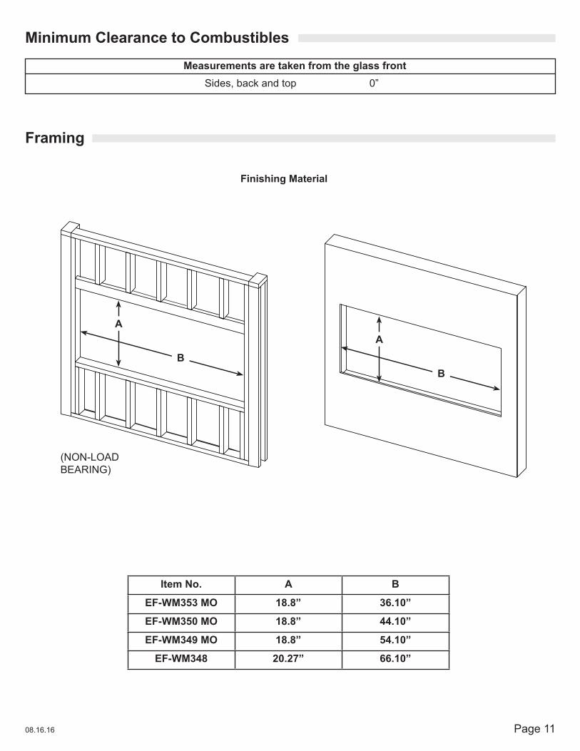
Minimum Clearance to Combustibles
Framing
Sides, back and top 0”
Measurements are taken from the glass front
Item No. A B
EF-WM353 MO 18.8” 36.10”
EF-WM350 MO 18.8” 44.10”
EF-WM349 MO 18.8” 54.10”
EF-WM348 20.27” 66.10”
Finishing Material
(NON-LOAD BEARING)
AA
BB
Page 12 08.16.16
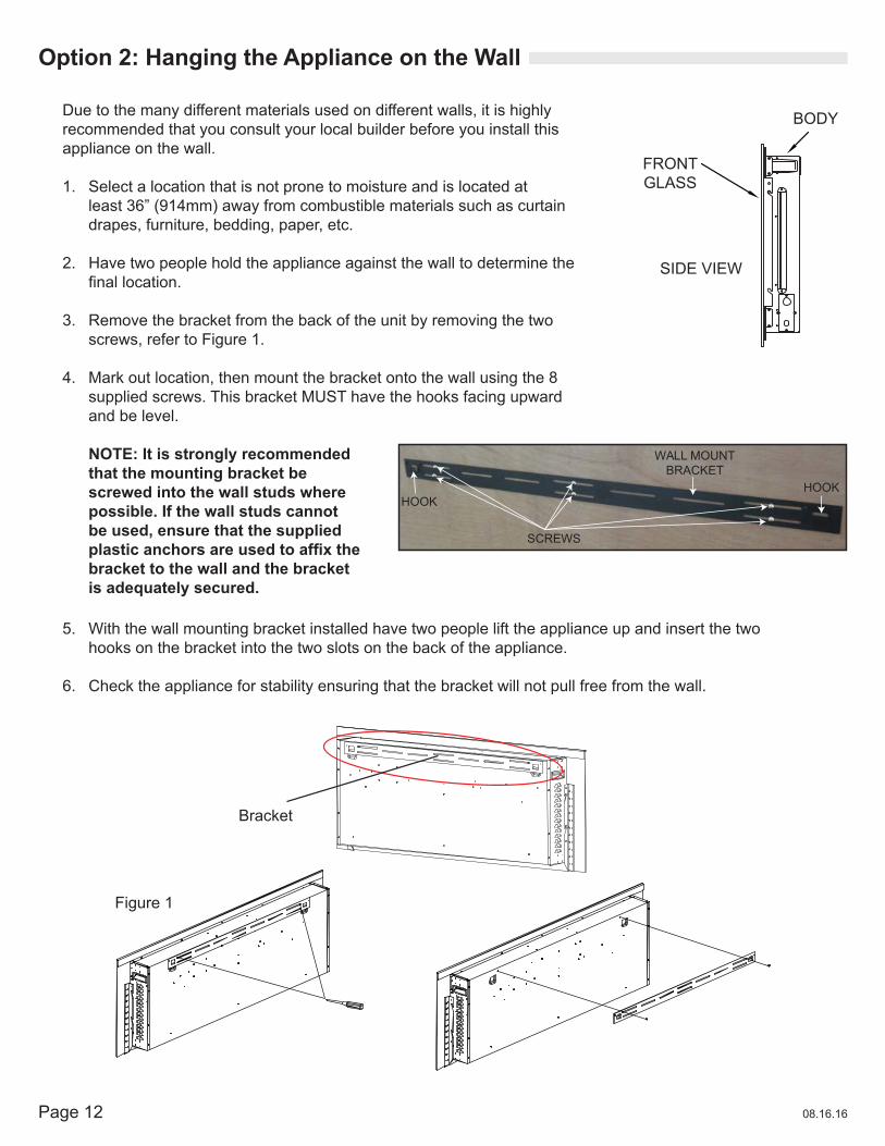
Option 2: Hanging the Appliance on the Wall
Due to the many different materials used on different walls, it is highly recommended that you consult your local builder before you install this appliance on the wall.
1. Select a location that is not prone to moisture and is located at least 36” (914mm) away from combustible materials such as curtain drapes, furniture, bedding, paper, etc.
2. Have two people hold the appliance against the wall to determine the finallocation.
3. Remove the bracket from the back of the unit by removing the two screws, refer to Figure 1.
4. Mark out location, then mount the bracket onto the wall using the 8 supplied screws. This bracket MUST have the hooks facing upward and be level.
WALL MOUNT BRACKET
SCREWS
HOOKHOOK
NOTE: It is strongly recommended that the mounting bracket be screwed into the wall studs where possible. If the wall studs cannot be used, ensure that the supplied plasticanchorsareusedtoaffixthebracket to the wall and the bracket is adequately secured.
5. With the wall mounting bracket installed have two people lift the appliance up and insert the two hooks on the bracket into the two slots on the back of the appliance.
6. Check the appliance for stability ensuring that the bracket will not pull free from the wall.
BODY
FRONTGLASS
SIDE VIEW
Figure 1
Bracket
Page 1308.16.16
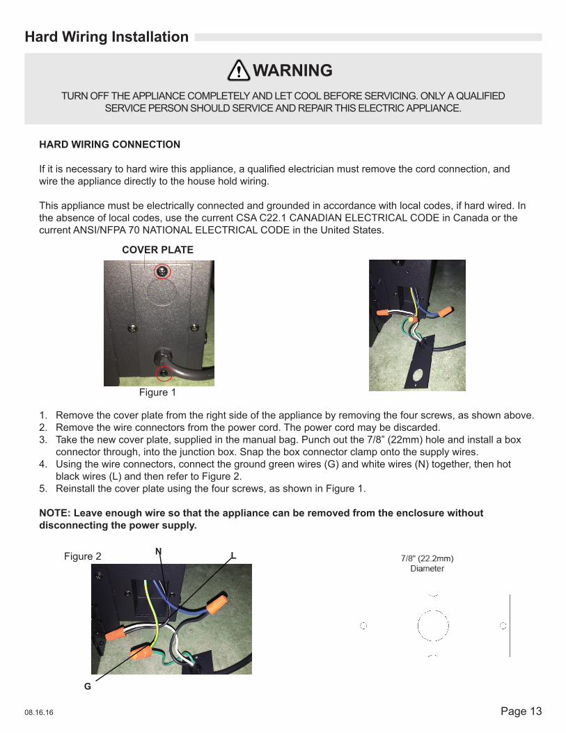
1. Remove the cover plate from the right side of the appliance by removing the four screws, as shown above.2. Remove the wire connectors from the power cord. The power cord may be discarded.3. Take the new cover plate, supplied in the manual bag. Punch out the 7/8” (22mm) hole and install a box
connector through, into the junction box. Snap the box connector clamp onto the supply wires.4. Using the wire connectors, connect the ground green wires (G) and white wires (N) together, then hot
black wires (L) and then refer to Figure 2.5. Reinstall the cover plate using the four screws, as shown in Figure 1.
NOTE: Leave enough wire so that the appliance can be removed from the enclosure without disconnecting the power supply.
HARD WIRING CONNECTION
Ifitisnecessarytohardwirethisappliance,aqualifiedelectricianmustremovethecordconnection,andwire the appliance directly to the house hold wiring.
This appliance must be electrically connected and grounded in accordance with local codes, if hard wired. In the absence of local codes, use the current CSA C22.1 CANADIAN ELECTRICAL CODE in Canada or the current ANSI/NFPA 70 NATIONAL ELECTRICAL CODE in the United States.
COVER PLATE
Figure 1
Figure 2
Hard Wiring Installation
TURN OFF THE APPLIANCE COMPLETELY AND LET COOL BEFORE SERVICING. ONLY A QUALIFIED SERVICE PERSON SHOULD SERVICE AND REPAIR THIS ELECTRIC APPLIANCE.
WARNING
G
N L
Page 14 08.16.16
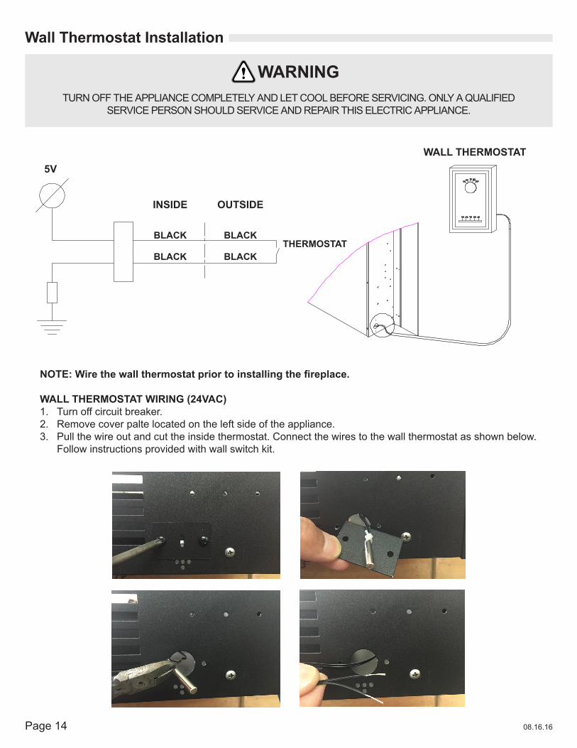
Wall Thermostat Installation
TURN OFF THE APPLIANCE COMPLETELY AND LET COOL BEFORE SERVICING. ONLY A QUALIFIED SERVICE PERSON SHOULD SERVICE AND REPAIR THIS ELECTRIC APPLIANCE.
WARNING
NOTE:Wirethewallthermostatpriortoinstallingthefireplace.
WALL THERMOSTAT WIRING (24VAC)1. Turn off circuit breaker.2. Remove cover palte located on the left side of the appliance.3. Pull the wire out and cut the inside thermostat. Connect the wires to the wall thermostat as shown below.
Follow instructions provided with wall switch kit.
5V
INSIDE OUTSIDE
BLACK
BLACK
BLACK
BLACKTHERMOSTAT
WALL THERMOSTAT
Page 1508.16.16
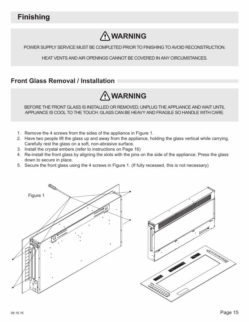
1. Remove the 4 screws from the sides of the appliance in Figure 1.2. Have two people lift the glass up and away from the appliance, holding the glass vertical while carrying.
Carefully rest the glass on a soft, non-abrasive surface.3. Install the crystal embers (refer to instructions on Page 16)4. Re-install the front glass by aligning the slots with the pins on the side of the appliance. Press the glass
down to secure in place.5. Secure the front glass using the 4 screws in Figure 1. (If fully recessed, this is not necessary)
Front Glass Removal / Installation
POWER SUPPLY SERVICE MUST BE COMPLETED PRIOR TO FINISHING TO AVOID RECONSTRUCTION.
HEAT VENTS AND AIR OPENINGS CANNOT BE COVERED IN ANY CIRCUMSTANCES.
BEFORE THE FRONT GLASS IS INSTALLED OR REMOVED, UNPLUG THE APPLIANCE AND WAIT UNTIL APPLIANCE IS COOL TO THE TOUCH. GLASS CAN BE HEAVY AND FRAGILE SO HANDLE WITH CARE.
WARNING
WARNING
FinishingFinishing
Figure 1
Page 16 08.16.16
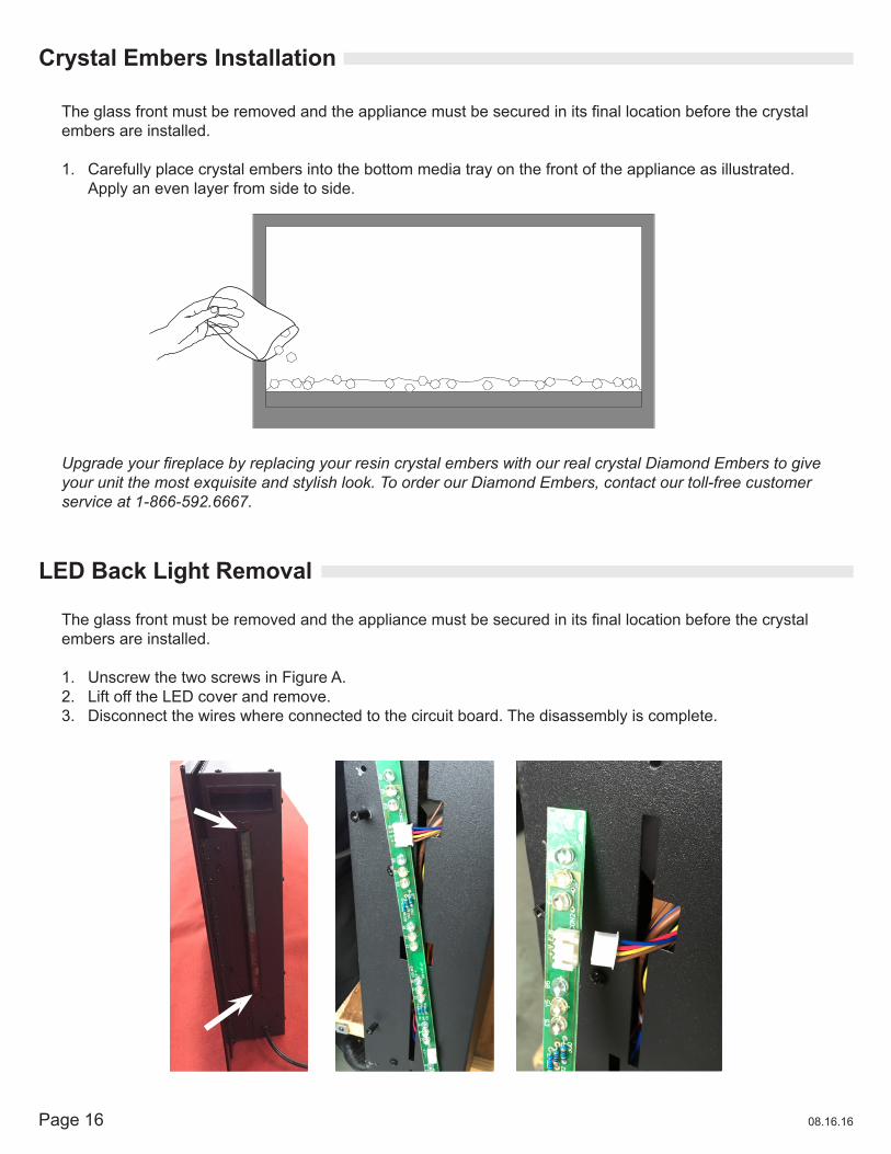
Theglassfrontmustberemovedandtheappliancemustbesecuredinitsfinallocationbeforethecrystalembers are installed.
1. Carefully place crystal embers into the bottom media tray on the front of the appliance as illustrated. Apply an even layer from side to side.
LED Back Light Removal
Theglassfrontmustberemovedandtheappliancemustbesecuredinitsfinallocationbeforethecrystalembers are installed.
1. Unscrew the two screws in Figure A.2. Lift off the LED cover and remove.3. Disconnect the wires where connected to the circuit board. The disassembly is complete.
Upgrade your fireplace by replacing your resin crystal embers with our real crystal Diamond Embers to give your unit the most exquisite and stylish look. To order our Diamond Embers, contact our toll-free customer service at 1-866-592.6667.
Crystal Embers Installation
Page 1708.16.16
Main Power Switch
Operating with Touch Panel
Once the appliance has been plugged into a grounded electrical outlet, it is ready to operate.NOTE: Ensure the house circuit breakers for the power supply are turned on. In the event of a powerfailure, the appliance will lose its memory function and will reset to factory mode when the powerreturns.
To turn unit power on:1. Plug in power cord.2. Turn on the power switch (located on the front bottom right side of the appliance).3. Verify the power is turned on when two ring tones are initiated.
The unit can be controlled by either the touch panel controls which are located on the right side of the front glass or the remote control.
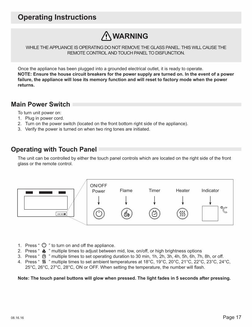
1. Press “ ” to turn on and off the appliance.2. Press “ ” multiple times to adjust between mid, low, on/off, or high brightness options3. Press “ ” multiple times to set operating duration to 30 min, 1h, 2h, 3h, 4h, 5h, 6h, 7h, 8h, or off.4. Press “ ” multiple times to set ambient temperatures at 18°C, 19°C, 20°C, 21°C, 22°C, 23°C, 24°C,
25°C,26°C,27°C,28°C,ONorOFF.Whensettingthetemperature,thenumberwillflash.
Note: The touch panel buttons will glow when pressed. The light fades in 5 seconds after pressing.
Operating Instructions
WHILE THE APPLIANCE IS OPERATING DO NOT REMOVE THE GLASS PANEL. THIS WILL CAUSE THE REMOTE CONTROL AND TOUCH PANEL TO DISFUNCTION.
WARNING
ON/OFFPower Flame Timer Heater Indicator
Page 18 08.16.16
Multi-functional Operating with Remote Control
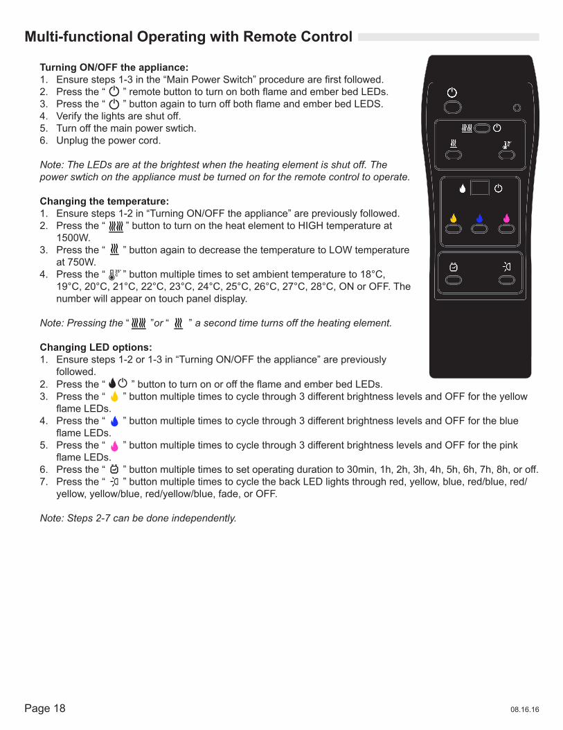
Turning ON/OFF the appliance:1. Ensuresteps1-3inthe“MainPowerSwitch”procedurearefirstfollowed.2. Pressthe“”remotebuttontoturnonbothflameandemberbedLEDs.3. Pressthe“”buttonagaintoturnoffbothflameandemberbedLEDS.4. Verify the lights are shut off.5. Turn off the main power swtich.6. Unplug the power cord.
Note: The LEDs are at the brightest when the heating element is shut off. The power swtich on the appliance must be turned on for the remote control to operate.
Changing the temperature:1. Ensure steps 1-2 in “Turning ON/OFF the appliance” are previously followed.2. Press the “ ” button to turn on the heat element to HIGH temperature at
1500W.3. Press the “ ” button again to decrease the temperature to LOW temperature
at 750W.4. Press the “ ” button multiple times to set ambient temperature to 18°C,
19°C, 20°C, 21°C, 22°C, 23°C, 24°C, 25°C, 26°C, 27°C, 28°C, ON or OFF. The number will appear on touch panel display.
Note: Pressing the “ ”or “ ” a second time turns off the heating element.
Changing LED options:1. Ensure steps 1-2 or 1-3 in “Turning ON/OFF the appliance” are previously
followed.2. Pressthe“”buttontoturnonorofftheflameandemberbedLEDs.3. Press the “ ” button multiple times to cycle through 3 different brightness levels and OFF for the yellow
flameLEDs.4. Press the “ ” button multiple times to cycle through 3 different brightness levels and OFF for the blue
flameLEDs.5. Press the “ ” button multiple times to cycle through 3 different brightness levels and OFF for the pink
flameLEDs.6. Press the “ ” button multiple times to set operating duration to 30min, 1h, 2h, 3h, 4h, 5h, 6h, 7h, 8h, or off.7. Press the “ ” button multiple times to cycle the back LED lights through red, yellow, blue, red/blue, red/
yellow, yellow/blue, red/yellow/blue, fade, or OFF.
Note: Steps 2-7 can be done independently.
Page 1908.16.16
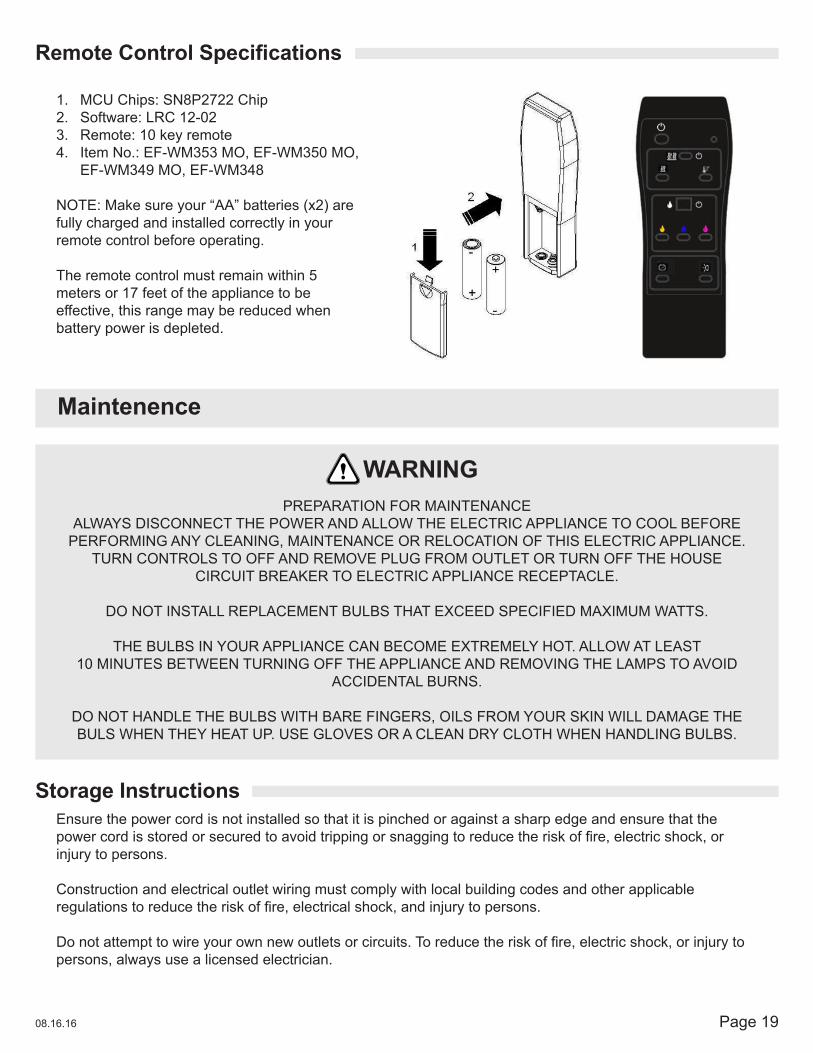
RemoteControlSpecifications
Storage Instructions
1. MCU Chips: SN8P2722 Chip2. Software: LRC 12-023. Remote: 10 key remote 4. Item No.: EF-WM353 MO, EF-WM350 MO,
EF-WM349 MO, EF-WM348
NOTE: Make sure your “AA” batteries (x2) are fully charged and installed correctly in your remote control before operating.
The remote control must remain within 5 meters or 17 feet of the appliance to be effective, this range may be reduced when battery power is depleted.
Maintenence
PREPARATION FOR MAINTENANCEALWAYS DISCONNECT THE POWER AND ALLOW THE ELECTRIC APPLIANCE TO COOL BEFORE
PERFORMING ANY CLEANING, MAINTENANCE OR RELOCATION OF THIS ELECTRIC APPLIANCE.TURN CONTROLS TO OFF AND REMOVE PLUG FROM OUTLET OR TURN OFF THE HOUSE
CIRCUIT BREAKER TO ELECTRIC APPLIANCE RECEPTACLE.
DO NOT INSTALL REPLACEMENT BULBS THAT EXCEED SPECIFIED MAXIMUM WATTS.
THE BULBS IN YOUR APPLIANCE CAN BECOME EXTREMELY HOT. ALLOW AT LEAST10 MINUTES BETWEEN TURNING OFF THE APPLIANCE AND REMOVING THE LAMPS TO AVOID
ACCIDENTAL BURNS.
DO NOT HANDLE THE BULBS WITH BARE FINGERS, OILS FROM YOUR SKIN WILL DAMAGE THEBULS WHEN THEY HEAT UP. USE GLOVES OR A CLEAN DRY CLOTH WHEN HANDLING BULBS.
WARNING
Ensure the power cord is not installed so that it is pinched or against a sharp edge and ensure that the powercordisstoredorsecuredtoavoidtrippingorsnaggingtoreducetheriskoffire,electricshock,orinjury to persons.
Construction and electrical outlet wiring must comply with local building codes and other applicable regulationstoreducetheriskoffire,electricalshock,andinjurytopersons.
Donotattempttowireyourownnewoutletsorcircuits.Toreducetheriskoffire,electricshock,orinjurytopersons, always use a licensed electrician.

Page 20 08.16.16
_
+
[
LRC16 FR-4
2014/09/18
SHENGYI
+E
BY
F�N
FIRE_Y
�-N1
F�N-N
1
L���_BL���_Y
����R1
�-N1
�-L1
H1
H2
RF
SI�1
IC2
R-N
1
REL�Y-H
1
��C-�FF
REL�Y-H
2
��C-�FF
REL�Y-H
�
��C-�FF
����1�E��
����2
FIRE_B
LE�-H��
EY
B+
+B
YE
C� N2
C�N1
+E
BY
+
E
BY
Y�Y2Y1E�
E2E1
C�N1B�
B2B1 B11 B12
C�N2
E11 E12
Y11 Y12
ENCL�
����
_
S�
+CL
SI�1
C�N
2C
�N1
C�N
2C
�N1
-
���� ENCL�
1
2G � � F
G C E �
+ CL
S�
R�8
-1�
FR-4
20
1�/0
4/16 SH
ENG
YI
CN2
�E���I�E���ER FL��E
Wiring Diagram
TURN OFF THE APPLIANCE COMPLETELY AND LET COOL BEFORE SERVICING. ONLY A QUALIFIED SERVICE PERSON SHOULD SERVICE AND REPAIR THIS ELECTRIC APPLIANCE.
WARNING
FIRE ELEMENT
EMBER
BACKLIGHT 1
BACKLIGHT 2
BUTTONPOWER CORD
SWITC
H
REC
EIVER
TEMPER
ATUR
E SEN
SOR
HEATIN
G ELEM
ENT
Page 2108.16.16
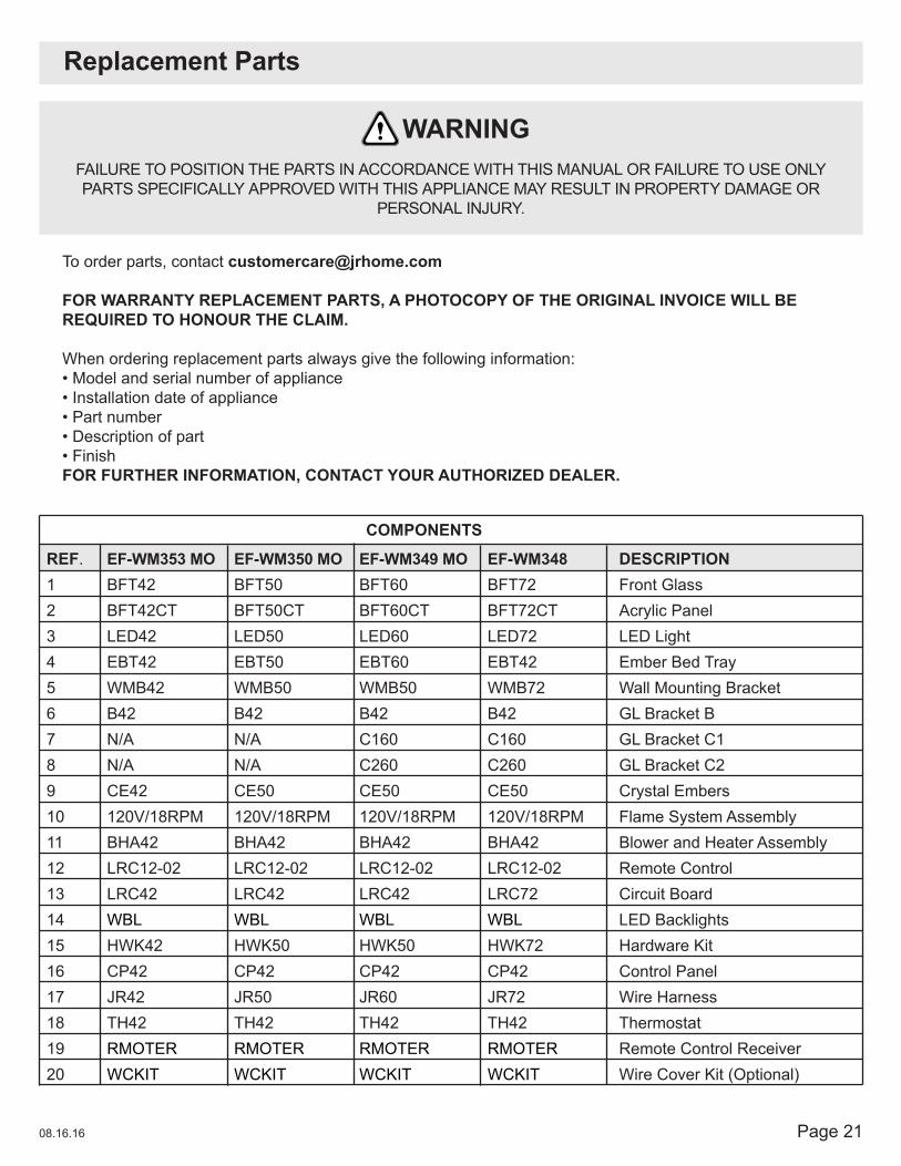
Replacement Parts
FAILURE TO POSITION THE PARTS IN ACCORDANCE WITH THIS MANUAL OR FAILURE TO USE ONLY PARTS SPECIFICALLY APPROVED WITH THIS APPLIANCE MAY RESULT IN PROPERTY DAMAGE OR
PERSONAL INJURY.
WARNING
To order parts, contact [email protected]
FOR WARRANTY REPLACEMENT PARTS, A PHOTOCOPY OF THE ORIGINAL INVOICE WILL BE REQUIRED TO HONOUR THE CLAIM.
When ordering replacement parts always give the following information:•Modelandserialnumberofappliance•Installationdateofappliance•Partnumber•Descriptionofpart•FinishFOR FURTHER INFORMATION, CONTACT YOUR AUTHORIZED DEALER.
REF.1234567891011121314151617181920
EF-WM353 MOBFT42BFT42CTLED42EBT42WMB42B42N/AN/ACE42120V/18RPMBHA42LRC12-02LRC42WBLHWK42CP42JR42TH42RMOTERWCKIT
EF-WM350 MOBFT50BFT50CTLED50EBT50WMB50B42N/AN/ACE50120V/18RPMBHA42LRC12-02LRC42WBLHWK50CP42JR50TH42RMOTERWCKIT
EF-WM349 MOBFT60BFT60CTLED60EBT60WMB50B42C160C260CE50120V/18RPMBHA42LRC12-02LRC42WBLHWK50CP42JR60TH42RMOTERWCKIT
EF-WM348BFT72BFT72CTLED72EBT42WMB72B42C160C260CE50120V/18RPMBHA42LRC12-02LRC72WBLHWK72CP42JR72TH42RMOTERWCKIT
DESCRIPTIONFront GlassAcrylic PanelLED LightEmber Bed TrayWall Mounting BracketGL Bracket BGL Bracket C1GL Bracket C2Crystal EmbersFlame System AssemblyBlower and Heater AssemblyRemote ControlCircuit BoardLED BacklightsHardware KitControl PanelWire HarnessThermostatRemote Control ReceiverWire Cover Kit (Optional)
COMPONENTS

Page 22 08.16.16
NOTE: Care must be taken when removing and disposing of any broken glass or damaged components. Be sure to vacuum up any broken glass from inside the appliance before operation.
Replacement Parts Diagram
FAILURE TO POSITION THE PARTS IN ACCORDANCE WITH THIS MANUAL OR FAILURE TO USE ONLY PARTS SPECIFICALLY APPROVED WITH THIS APPLIANCE MAY RESULT IN PROPERTY DAMAGE OR
PERSONAL INJURY.
WARNING
1
2
3
410 11
13
14
5
67
8
12 15 16
17 18 2019
9

Page 2308.16.16
Troubleshooting
TURN OFF THE APPLIANCE COMPLETELY AND LET COOL BEFORE SERVICING. ONLY A QUALIFIED SERVICE PERSON SHOULD SERVICE AND REPAIR THIS ELECTRIC APPLIANCE.
WARNING
Symptom Problem Test Solution
Dimornoflame/ Ember bed is not glowing or dimming
LED’s are burnt out or malfunctioning
Inspect the LED’s and replace them if necessary
No warm air coming out of appliance
Room temperature is higher than the appliance setting (if it is set to room temperature)
Reset temperature setting
Heater is burnt out Inspect the burner and heater assembly and replace it if necessary
Appliance turns off and will not turn on
Appliance has overheated and safety thermal switch has tripped
Unplug power cord and allow appliance to cool for 15 minutes, then plug in the power cord and turn the power ON
House circuit breaker has tripped
Reset house circuit breaker
Appliance will not switch on when the Power button is turned ON
Appliance is not plugged into an electrical outlet
Check plug and plug it into a 120V outlet
Appliance has overheated and safety thermal switch has tripped
Unplug power cord and allow appliance to cool for 15 minutes, then plug in the power cord and turn the power ON
Circuit board is burnt out Inspect the circuit board and replace it if necessary
Remote control does not work Low battery Replace battteries in remote control
Heater shuts off automatically Room is too warm The heater has a built-in thermostat so it will shut off automatically once the pre-set temperature is reached. It will also turn on automatically if the room temperature drops below the pre-set temperature.
Touch panel/ Remote Control do not work
The front glass has moved or is not secured properly
Unplug the appliance, if the appliance is recessed into the wall, shut off house circuit breaker. Ensure the front glass is in the correct positionandissittingflattotheappliancetouchpanel. After 10 seconds, plug in or turn on the appliance to reset it.
Page 24 08.16.16
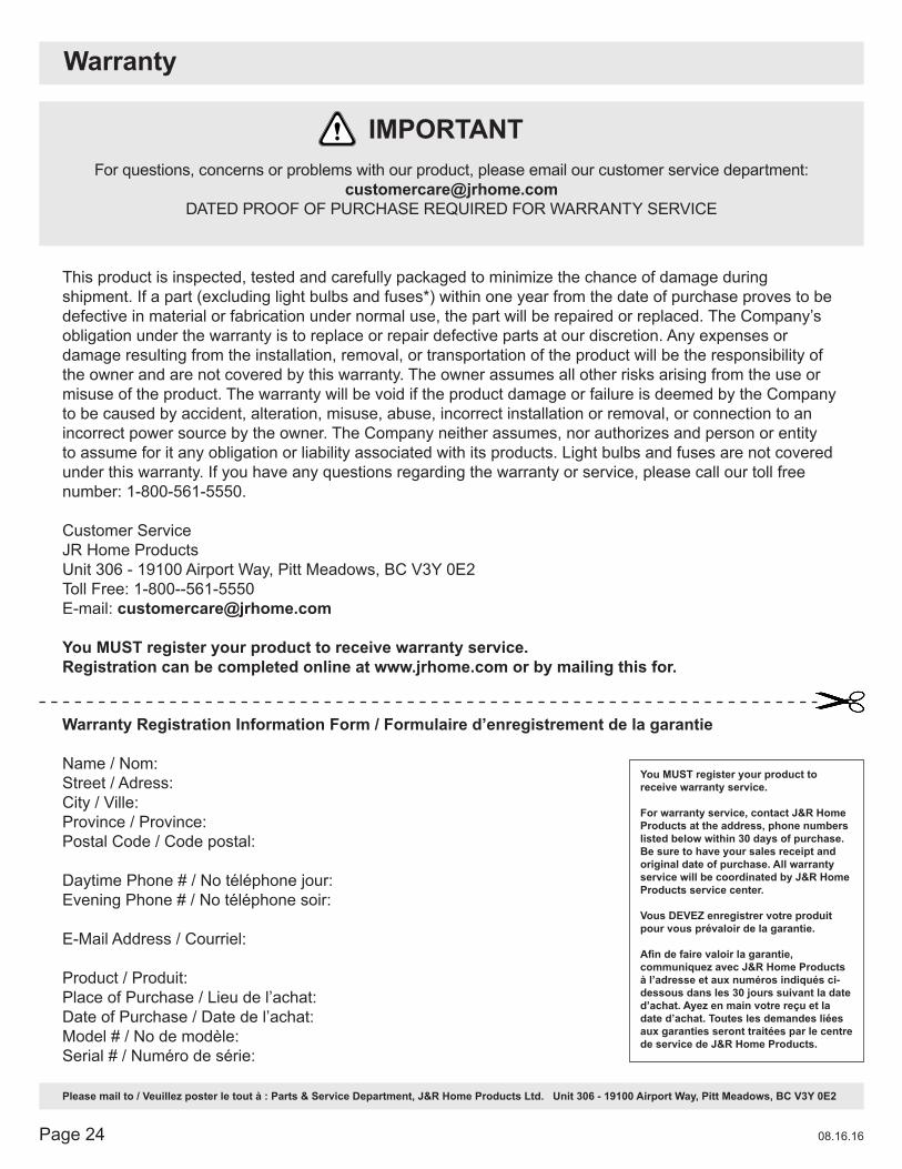
Warranty Registration Information Form / Formulaire d’enregistrement de la garantie
Name / Nom:Street / Adress:City / Ville:Province / Province:Postal Code / Code postal:
Daytime Phone # / No téléphone jour:Evening Phone # / No téléphone soir:
E-Mail Address / Courriel:
Product / Produit:Place of Purchase / Lieu de l’achat:Date of Purchase / Date de l’achat:Model # / No de modèle:Serial # / Numéro de série:
Please mail to / Veuillez poster le tout à : Parts & Service Department, J&R Home Products Ltd. Unit 306 - 19100 Airport Way, Pitt Meadows, BC V3Y 0E2
Warranty
This product is inspected, tested and carefully packaged to minimize the chance of damage during shipment. If a part (excluding light bulbs and fuses*) within one year from the date of purchase proves to be defective in material or fabrication under normal use, the part will be repaired or replaced. The Company’s obligation under the warranty is to replace or repair defective parts at our discretion. Any expenses or damage resulting from the installation, removal, or transportation of the product will be the responsibility of the owner and are not covered by this warranty. The owner assumes all other risks arising from the use or misuse of the product. The warranty will be void if the product damage or failure is deemed by the Company to be caused by accident, alteration, misuse, abuse, incorrect installation or removal, or connection to an incorrect power source by the owner. The Company neither assumes, nor authorizes and person or entity to assume for it any obligation or liability associated with its products. Light bulbs and fuses are not covered under this warranty. If you have any questions regarding the warranty or service, please call our toll free number: 1-800-561-5550.
Customer ServiceJR Home ProductsUnit 306 - 19100 Airport Way, Pitt Meadows, BC V3Y 0E2Toll Free: 1-800--561-5550E-mail: [email protected]
You MUST register your product to receive warranty service. Registration can be completed online at www.jrhome.com or by mailing this for.
You MUST register your product to receive warranty service.
For warranty service, contact J&R Home Products at the address, phone numbers listed below within 30 days of purchase. Be sure to have your sales receipt and original date of purchase. All warranty service will be coordinated by J&R Home Products service center.
Vous DEVEZ enregistrer votre produit pour vous prévaloir de la garantie.
Afindefairevaloirlagarantie,communiquez avec J&R Home Products à l’adresse et aux numéros indiqués ci-dessous dans les 30 jours suivant la date d’achat. Ayez en main votre reçu et la date d’achat. Toutes les demandes liées aux garanties seront traitées par le centre de service de J&R Home Products.
For questions, concerns or problems with our product, please email our customer service department: [email protected]
DATED PROOF OF PURCHASE REQUIRED FOR WARRANTY SERVICE
IMPORTANT