Embed Size (px)
Citation preview
PA
GE
1W3500/W4500 DIESEL
W35/45D Rev. 12/98
SPECIFICATIONS
Model W3500 Diesel W4500 DieselGVWR 12,000 lb. 14,500 lb.
WB 109 in./132.5 in./150 in./176 in.Engine GM/Isuzu 4-cylinder, in-line 4-cycle, turbocharged, intercooled, direct injection diesel.
Model/Displacement 4HE1-TC/290 CID (4.75 liters)HP (Gross) 142 HP/2800 RPM (Manual Transmission) 175 HP/2700 RPM (Automatic Transmission)Torque (Gross) 275 lb. ft. torque/1300 RPM 347 lb. ft. torque/2000 RPM
EquipmentDry element air cleaner with vertical intake; 2 rows 506 in2 radiator; 6 blade 18.7 in. diameter fan with viscous drive. Cold weather starting
device and an oil cooler.
Clutch Single, dry plate, 11.8 in. dia., actuated by self adjusting hydraulic master/slave cylinder.
Transmission MXA5C 5-speed manual, all forward gears synchronized. Fifth gear is direct.Steering Integral power steering 20.9:1 ratio. Tilt and telescoping steering column.
Front Axle Reverse Elliot “I” Beam rated at 6,830 lb.Suspension Semi-elliptical steel alloy leaf springs with stabilizer bar and shock absorbers.
GAWR 4700 lb. 5360 lb.Rear Axle Full floating single speed with hypoid gearing rated at 11,020 lb.
Suspension Semi-elliptical steel alloy leaf springs and shock absorbers.GAWR 7950 lb. 9880 lb.
Wheels 16 x 6.0 6–hole disc wheels, painted white.
Tires 215/85R-16E (10 pr) tubeless steel belted radials, all season front and rear.
BrakesDual circuit vacuum assisted hydraulic service brakes with load sensing proportioning valve in rear brake circuit and a metering valve between the
master cylinder and 6-way joint on the front brake lines. Disc front and self-adjusting outboard mounted drum rear. The parking brake is a mechani-cal, cable actuated, internal expanding drum type, transmission mounted. The exhaust brake is standard and is vacuum operated.
Fuel Tank 33 gal. cylindrical steel fuel tank mounted on right hand rail with fuel water separator mounted on rail.Frame ������ !$�� ������� ��!��� !�����! ����� ���� ��� ��� #��� !���"�� !�� !�!�� ����!� �� !�� ������ ����� !����!� ������ � � ��!��� ���"�" ���� ���� � � �������
Cab All steel low cab forward, BBC 68.0 in., 45° mechanical tilt with torsion assist.
EquipmentJersey knit covered high back driver’s seat with two occupant passenger seat. Two-way roof ventilator, dual cab mounted exterior mirrors.
Tilt and telescoping steering column. Tinted glass.
Electrical 12 Volt, negative ground, dual Delco maintenance free batteries, 750 CCA each, 80 Amp alternator with integral regulator.
OptionsAir Conditioning; AM/FM cassette stereo radio; PTO; engine block heater; engine oil pan heater; heated fuel/water separator; spare wheel; 6” stain-
less steel convex mirrors.
TransmissionsAisin 450-43 LE 4-speed overdrive automatic transmission with lock-up capability in 2nd, 3rd and 4th and PTO capability. PTO gears are
available in the 109 & 132.5 WB only.
NOTE: These selected specifications are subject to change without notice.
PA
GE2 W3500/W4500 DIESEL
W35/45D Rev. 12/98
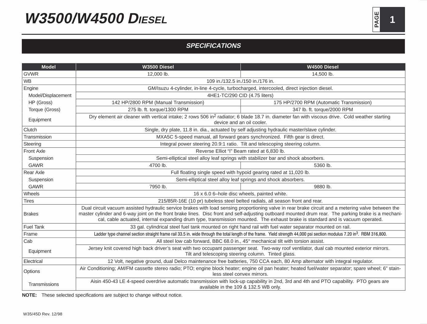
VEHICLE WEIGHTS, DIMENSIONS AND RATINGS

PA
GE
3W3500/W4500 DIESEL
W35/45D Rev. 12/98
Variable Chassis Dimensions
Unit WB CA* CE* OAL AF
Inch 109.0 88.4 131.5 199.5 43.1
Inch 132.5 111.9 155.0 223.0 43.1
Inch 150.0 129.4 172.5 240.5 43.1
Inch 176.0 155.4 198.5 266.3 43.1
* Effective CA & CE are CA or CE less BOC.
Dimension Constants
Code Inches Code Inches Code Inches
AH 7.9 BW 83.3 FH 32.0
AW 65.6 CW 65.0
BA 47.4 FW 33.5
BBC 68.0 OH 87.4
BOC 9.25 OW 78.5
12,000 lb. GVWR Manual Transmission Model
Chassis Cab and Maximum Payload Weights
Model WB Unit Front Rear Total Payload
NA1 109.0 in. lb. 3,638 1,587 5,225 6,775
NA2 132.5 in. lb. 3,682 1,609 5,291 6,709
NA3 150.0 in. lb. 3,726 1,631 5,357 6,643
NA4 176.0 in. lb. 3,770 1,653 5,423 6,577
14,500 lb. GVWR Manual Transmission Model
Chassis Cab and Maximum Payload Weights
Model WB Unit Front Rear Total Payload
NE1 109.0 in. lb. 3,649 1,587 5,236 9,264
NE2 132.5 in. lb. 3,693 1,609 5,302 9,198
NE3 150.0 in. lb. 3,737 1,631 5,368 9,132
NE4 176.0 in. lb. 3,781 1,653 5,434 9,066
12,000 lb. GVWR with Aisin Automatic Transmission Model
Chassis Cab and Maximum Payload Weights
Model WB Unit Front Rear Total Payload
NB1 109.0 in. lb. 3,704 1,631 5,335 6,665
NB2 132.5 in. lb. 3,748 1,653 5,401 6,599
NB3 150.0 in. lb. 3,792 1,675 5,467 6,533
NB4 176.0 in. lb. 3,836 1,698 5,534 6,466
14,500 lb. GVWR with Aisin Automatic Transmission Model
Chassis Cab and Maximum Payload Weights
Model WB Unit Front Rear Total Payload
NF1 109.0 in. lb. 3,715 1,631 5,346 9,154
NF2 132.5 in. lb. 3,759 1,653 5,412 9,088
NF3 150.0 in. lb. 3,803 1,675 5,478 9,022
NF4 176.0 in. lb. 3,847 1,698 5,545 8,955
Vehicle weight Limits:
GVWR
Designed Maximum 12,000 lb. 14,500 lb.
GAWR, Front 4,700 lb. 5,360 lb.
GAWR, Rear 7,950 lb. 9,880 lb.
Technical Notes:
Chassis Curb Weigh t reflects standard equipment and fuel, but no driver or payload.
Maximum Payload Weight is the allowed maximum for equipment, body, payloadand driver and is calculated by subtracting chassis curb weight from the GVWR.
Model Descriptions
The W3500/W4500 Series Diesel features a low cab forward design that is ideallysuited for inter-city type applications. The low cab forward design minimizes overalllength for a given body length and in conjunction with the set back front axle position-ing provides excellent weight distribution. The 42.5° inside wheel cut angle coupledwith integral power steering make it an extremely well maneuverable truck.
PA
GE4 W3500/W4500 DIESEL
W35/45D Rev. 12/98
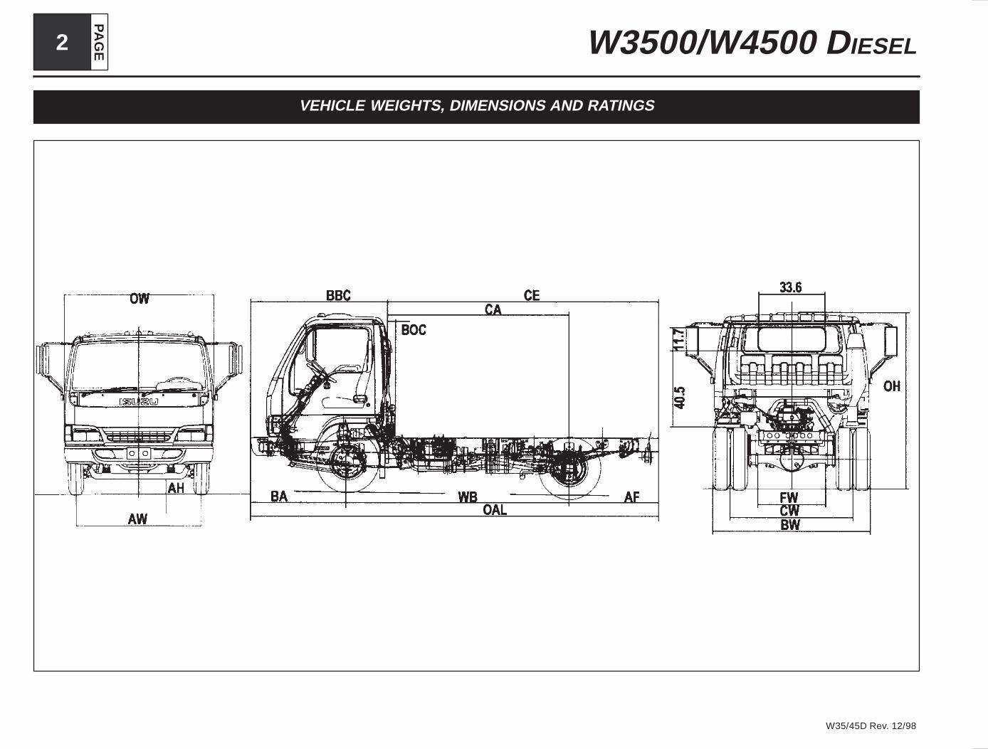
FRAME & CROSSMEMBER SPECIFICATIONS
Type AA
Type BB
Type CC
Type DD
Model Wheel Base Frame Cross Member Type/LocationModel Wheel Base Frame
Thick A B C-M/T C-A/T D-M/T D-A/T E F G
W3500/W4500 109 0.24 37.0 28.3 8.4 8.4 AA 40.5 AA 44.7 — CC 26.0 DD 33.0
W3500/W4500 132.5 0.24 37.0 28.3 8.4 8.4 AA 40.5 AA 44.7 BB 59.4 CC 26.0 DD 33.0
W3500/W4500 150.0 0.24 37.0 28.3 8.4 8.4 AA 40.5 AA 44.7 BB 59.4 CC 26.0 DD 33.0
W3500/W4500 176.0 .024 37.0 28.3 8.4 8.4 40.5 44.7 59.4 26.0 33.0
PA
GE
5W3500/W4500 DIESEL
W35/45D Rev. 12/98
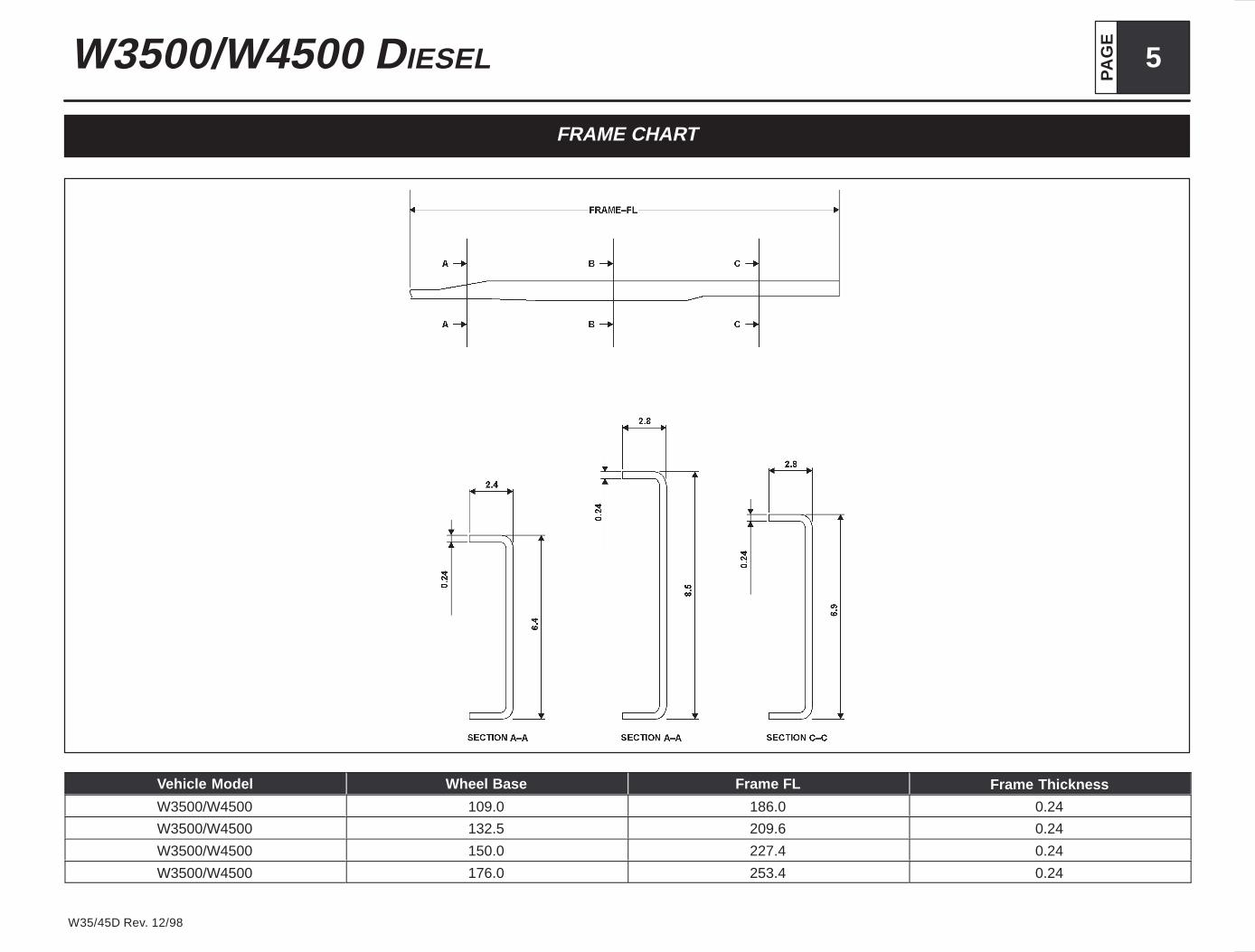
FRAME CHART
Vehicle Model Wheel Base Frame FL Frame Thickness
W3500/W4500 109.0 186.0 0.24
W3500/W4500 132.5 209.6 0.24
W3500/W4500 150.0 227.4 0.24
W3500/W4500 176.0 253.4 0.24

PA
GE6 W3500/W4500 DIESEL
W35/45D Rev. 12/98
AUXILIARY VIEWS
NOTE: Frame mounted fuel tank available on 109:, 132.5”, 150: and 176” WB: In frame mounted tank available as optional replacement for frame mountedtank on 109”, 132.5”, 150” and 176” WB.
* Allow 3” additional for battery box opening clearance.
PA
GE
7W3500/W4500 DIESEL
W35/45D Rev. 12/98
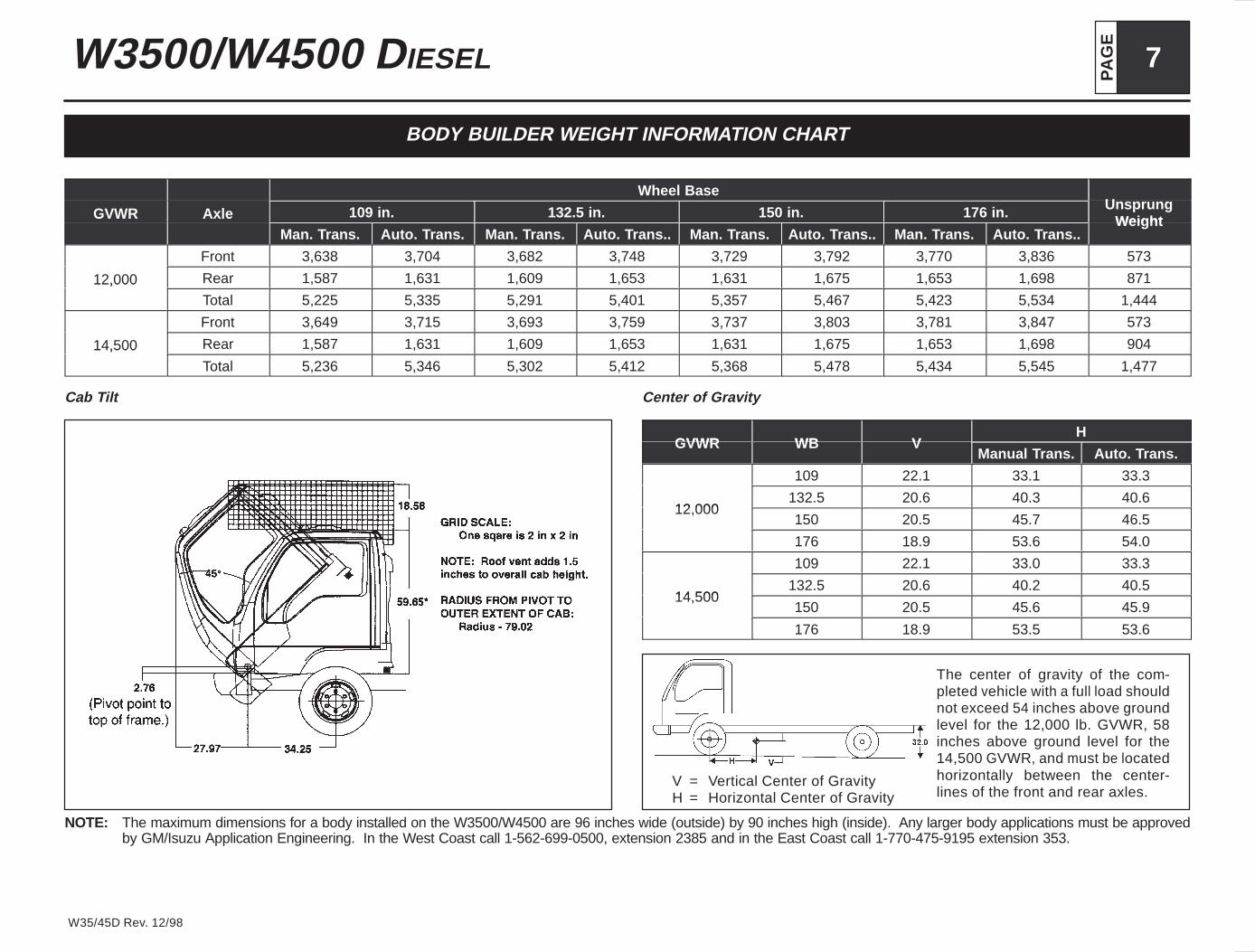
BODY BUILDER WEIGHT INFORMATION CHART
Wheel BaseU
GVWR Axle 109 in. 132.5 in. 150 in. 176 in. UnsprungWeightGVWR Axle
Man. Trans. Auto. Trans. Man. Trans. Auto. Trans.. Man. Trans. Auto. Trans.. Man. Trans. Auto. Trans..Weight
Front 3,638 3,704 3,682 3,748 3,729 3,792 3,770 3,836 573
12,000 Rear 1,587 1,631 1,609 1,653 1,631 1,675 1,653 1,698 87112,000Total 5,225 5,335 5,291 5,401 5,357 5,467 5,423 5,534 1,444
Front 3,649 3,715 3,693 3,759 3,737 3,803 3,781 3,847 573
14,500 Rear 1,587 1,631 1,609 1,653 1,631 1,675 1,653 1,698 90414,500
Total 5,236 5,346 5,302 5,412 5,368 5,478 5,434 5,545 1,477
Cab Tilt Center of Gravity
GVWR WB VH
GVWR WB VManual Trans. Auto. Trans.
109 22.1 33.1 33.3
12 000132.5 20.6 40.3 40.6
12,000150 20.5 45.7 46.5
176 18.9 53.6 54.0
109 22.1 33.0 33.3
14 500132.5 20.6 40.2 40.5
14,500150 20.5 45.6 45.9
176 18.9 53.5 53.6
The center of gravity of the com-pleted vehicle with a full load shouldnot exceed 54 inches above groundlevel for the 12,000 lb. GVWR, 58inches above ground level for the14,500 GVWR, and must be locatedhorizontally between the center-lines of the front and rear axles.
V = Vertical Center of GravityH = Horizontal Center of Gravity
NOTE: The maximum dimensions for a body installed on the W3500/W4500 are 96 inches wide (outside) by 90 inches high (inside). Any larger body applications must be approvedby GM/Isuzu Application Engineering. In the West Coast call 1-562-699-0500, extension 2385 and in the East Coast call 1-770-475-9195 extension 353.
PA
GE8 W3500/W4500 DIESEL
W35/45D Rev. 12/98
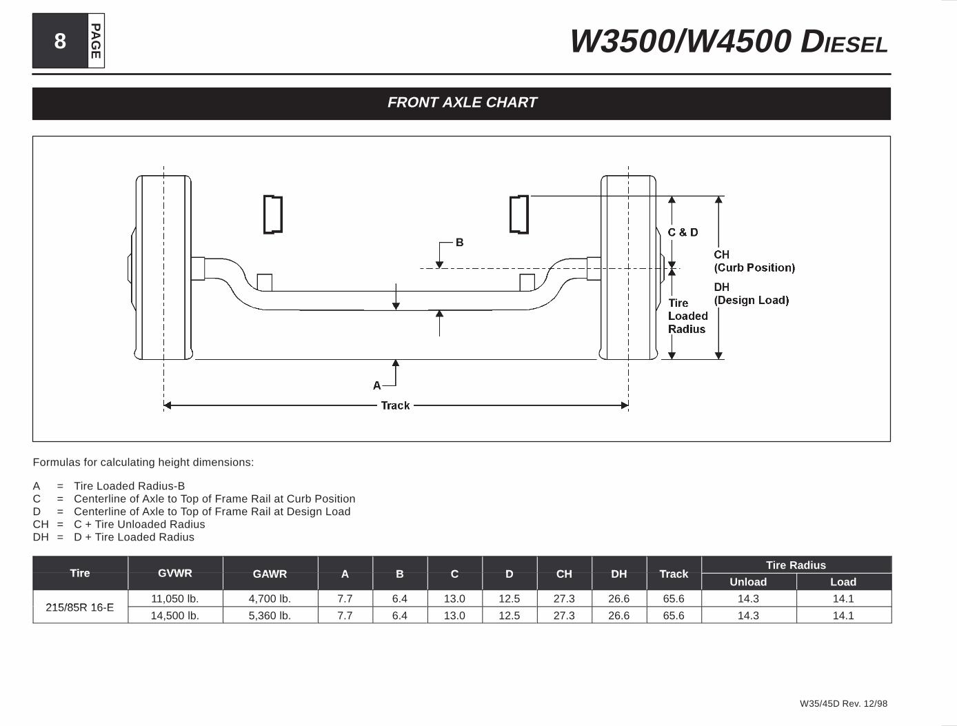
FRONT AXLE CHART
Formulas for calculating height dimensions:
A = Tire Loaded Radius-BC = Centerline of Axle to Top of Frame Rail at Curb PositionD = Centerline of Axle to Top of Frame Rail at Design LoadCH = C + Tire Unloaded RadiusDH = D + Tire Loaded Radius
Tire GVWR GAWR A B C D CH DH TrackTire Radius
Tire GVWR GAWR A B C D CH DH TrackUnload Load
215/85R 16 E11,050 lb. 4,700 lb. 7.7 6.4 13.0 12.5 27.3 26.6 65.6 14.3 14.1
215/85R 16-E14,500 lb. 5,360 lb. 7.7 6.4 13.0 12.5 27.3 26.6 65.6 14.3 14.1
PA
GE
9W3500/W4500 DIESEL
W35/45D Rev. 12/98
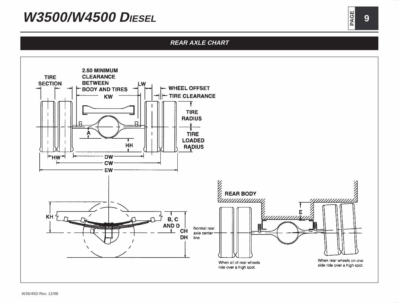
REAR AXLE CHART
PA
GE10 W3500/W4500 DIESEL
W35/45D Rev. 12/98
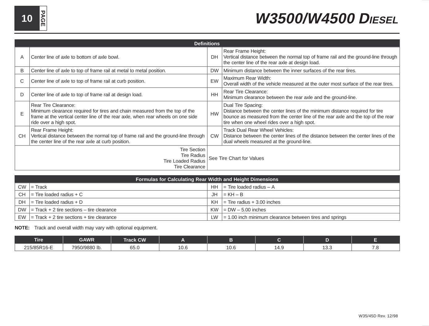
Definitions
A Center line of axle to bottom of axle bowl. DHRear Frame Height:Vertical distance between the normal top of frame rail and the ground-line throughthe center line of the rear axle at design load.
B Center line of axle to top of frame rail at metal to metal position. DW Minimum distance between the inner surfaces of the rear tires.
C Center line of axle to top of frame rail at curb position. EWMaximum Rear Width:Overall width of the vehicle measured at the outer most surface of the rear tires.
D Center line of axle to top of frame rail at design load. HHRear Tire Clearance:Minimum clearance between the rear axle and the ground-line.
E
Rear Tire Clearance:Minimum clearance required for tires and chain measured from the top of theframe at the vertical center line of the rear axle, when rear wheels on one sideride over a high spot.
HW
Dual Tire Spacing:Distance between the center lines of the minimum distance required for tirebounce as measured from the center line of the rear axle and the top of the reartire when one wheel rides over a high spot.
CHRear Frame Height:Vertical distance between the normal top of frame rail and the ground-line throughthe center line of the rear axle at curb position.
CWTrack Dual Rear Wheel Vehicles:Distance between the center lines of the distance between the center lines of thedual wheels measured at the ground-line.
Tire SectionTire Radius
Tire Loaded RadiusTire Clearance
See Tire Chart for Values
Formulas for Calculating Rear Width and Height Dimensions
CW = Track HH = Tire loaded radius – A
CH = Tire loaded radius + C JH = KH – B
DH = Tire loaded radius + D KH = Tire radius + 3.00 inches
DW = Track + 2 tire sections – tire clearance KW = DW – 5.00 inches
EW = Track + 2 tire sections + tire clearance LW = 1.00 inch minimum clearance between tires and springs
NOTE: Track and overall width may vary with optional equipment.
Tire GAWR Track CW A B C D E
215/85R16-E 7950/9880 lb. 65.0 10.6 10.6 14.9 13.3 7.8
PA
GE
11W3500/W4500 DIESEL
W35/45D Rev. 12/98
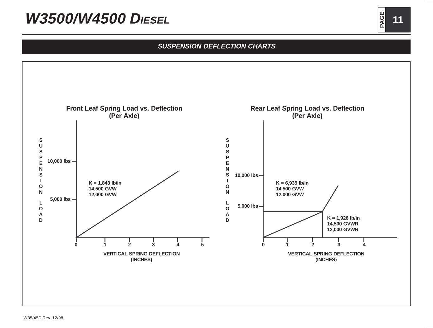
SUSPENSION DEFLECTION CHARTS
K = 1,843 lb/in14,500 GVW12,000 GVW
0 1 2 3 4 5
Front Leaf Spring Load vs. Deflection(Per Axle)
10,000 lbs
5,000 lbs
K = 6,935 lb/in14,500 GVW12,000 GVW
0 1 2 3 4
Rear Leaf Spring Load vs. Deflection(Per Axle)
K = 1,926 lb/in14,500 GVWR12,000 GVWR
SUSPENSION
LOAD
10,000 lbs
5,000 lbs
SUSPENSION
LOAD
VERTICAL SPRING DEFLECTION(INCHES)
VERTICAL SPRING DEFLECTION(INCHES)
PA
GE12 W3500/W4500 DIESEL
W35/45D Rev. 12/98
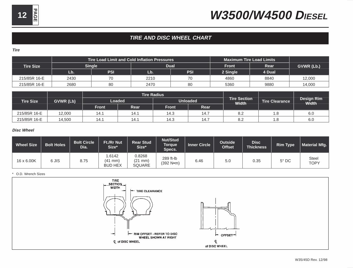
TIRE AND DISC WHEEL CHART
Tire
Tire Load Limit and Cold Inflation Pressures Maximum Tire Load Limits
Tire Size Single Dual Front Rear GVWR (Lb.)Tire SizeLb. PSI Lb. PSI 2 Single 4 Dual
GVWR (Lb.)
215/85R 16-E 2430 70 2210 70 4860 8840 12,000
215/85R 16-E 2680 80 2470 80 5360 9880 14,000
Tire RadiusTi S ti D i Ri
Tire Size GVWR (Lb) Loaded Unloaded Tire SectionWidth Tire Clearance
Design RimWidthTire Size GVWR (Lb)
Front Rear Front RearWidth Tire Clearance Width
215/85R 16-E 12,000 14.1 14.1 14.3 14.7 8.2 1.8 6.0
215/85R 16-E 14,500 14.1 14.1 14.3 14.7 8.2 1.8 6.0
Disc Wheel
Wheel Size Bolt HolesBolt Circle
Dia.Ft./Rr Nut
Size*Rear Stud
Size*
Nut/StudTorqueSpecs.
Inner CircleOutside
OffsetDisc
Thickness Rim Type Material Mfg.
16 x 6.00K 6 JIS 8.751.6142
(41 mm) BUD HEX
0.8268 (21 mm)SQUARE
289 ft-lb (392 N�m) 6.46 5.0 0.35 5° DC
Steel TOPY
* O.D. Wrench Sizes

PA
GE
13W3500/W4500 DIESEL
W35/45D Rev. 12/98
PROPELLER SHAFT
Plan View Side ViewWheel Base A
Manual Trans.A
Auto. Trans.B
Manual Trans.B
Auto. Trans.C
Manual Trans.C
Auto. Trans.D
Manual Trans.D
Auto. Trans.
109 in. — — 2.0° 2.3° — — 8.3° —
132.5 in. 0° 0° 2.4° 2.4° 4.4° 5° 6.2° 6.1°150 in. 0° 0° 2.4° 2.4° 2.5° 2.6° 6.4° 6.4°176 in. 0° 0° 1.7° 1.7° 2.8° 2.8° 4.5° 4.5°
NOTE: All driveline angles are at unloaded condition (Curb position with typical cargo body).

PA
GE14 W3500/W4500 DIESEL
W35/45D Rev. 12/98
Unit: Inch
Wheel Base 109 132.5 150 176
No. of Shafts 1 2 2 2
Trans. Type 5 Manual Trans. 4 Auto. Trans. 5 Manual Trans. 4 Auto. Trans. 5 Manual Trans. 4 Auto. Trans. 5 Manual Trans. 4 Auto. Trans.
Shaft #1 O.D. 3.25
Thickness 0.091
Length 44.5 39.1 29.7 24.3 47.4 41.9 59.1 53.7
Type B B A A A A A A
Shaft #2 O.D. 3.25
Thickness 0.091
Length N/A N/A 38.3 38.3 38.3 38.3 52.6 52.6
Type N/A N/A B B B B B B
Type Description Illustration
Type A 1st shaft in 2 piece driveline
Length
Type B 1st shaft in 1 piece driveline2nd shaft in 2 piece driveline
Length
PA
GE
15W3500/W4500 DIESEL
W35/45D Rev. 12/98
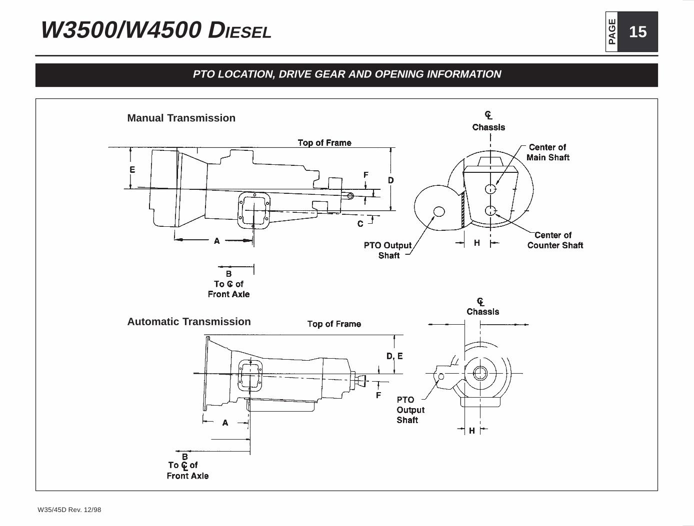
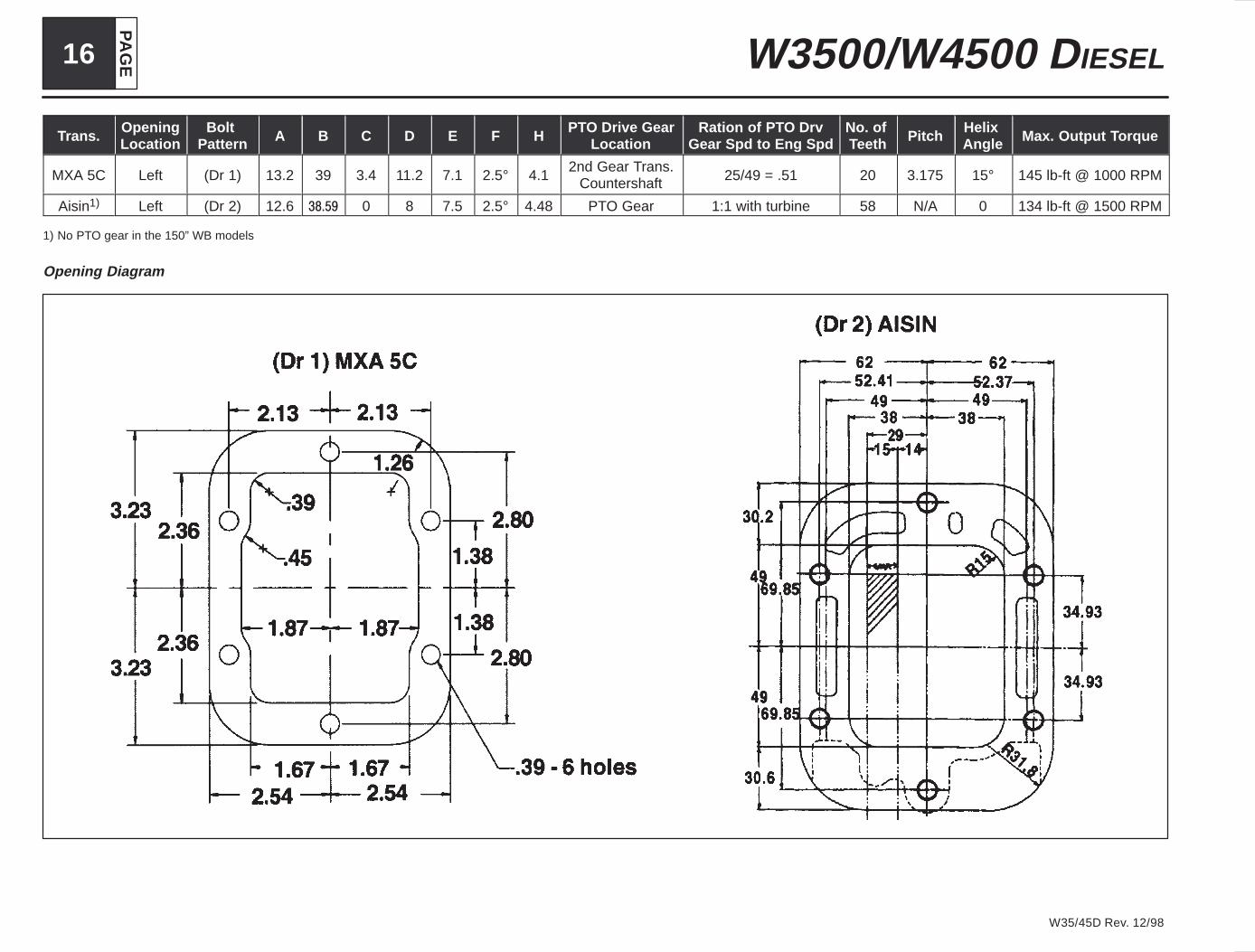
PTO LOCATION, DRIVE GEAR AND OPENING INFORMATION
Manual Transmission
Automatic Transmission
PA
GE16 W3500/W4500 DIESEL
W35/45D Rev. 12/98
Trans.OpeningLocation
Bolt Pattern A B C D E F H
PTO Drive GearLocation
Ration of PT O DrvGear Spd to Eng Spd
No. of Teeth Pitch
Helix Angle Max. Output Torque
MXA 5C Left (Dr 1) 13.2 39 3.4 11.2 7.1 2.5° 4.12nd Gear Trans.
Countershaft 25/49 = .51 20 3.175 15° 145 lb-ft @ 1000 RPM
Aisin1) Left (Dr 2) 12.6 ����� 0 8 7.5 2.5° 4.48 PTO Gear 1:1 with turbine 58 N/A 0 134 lb-ft @ 1500 RPM
1) No PTO gear in the 150” WB models
Opening Diagram
PA
GE
17W3500/W4500 DIESEL
W35/45D Rev. 12/98
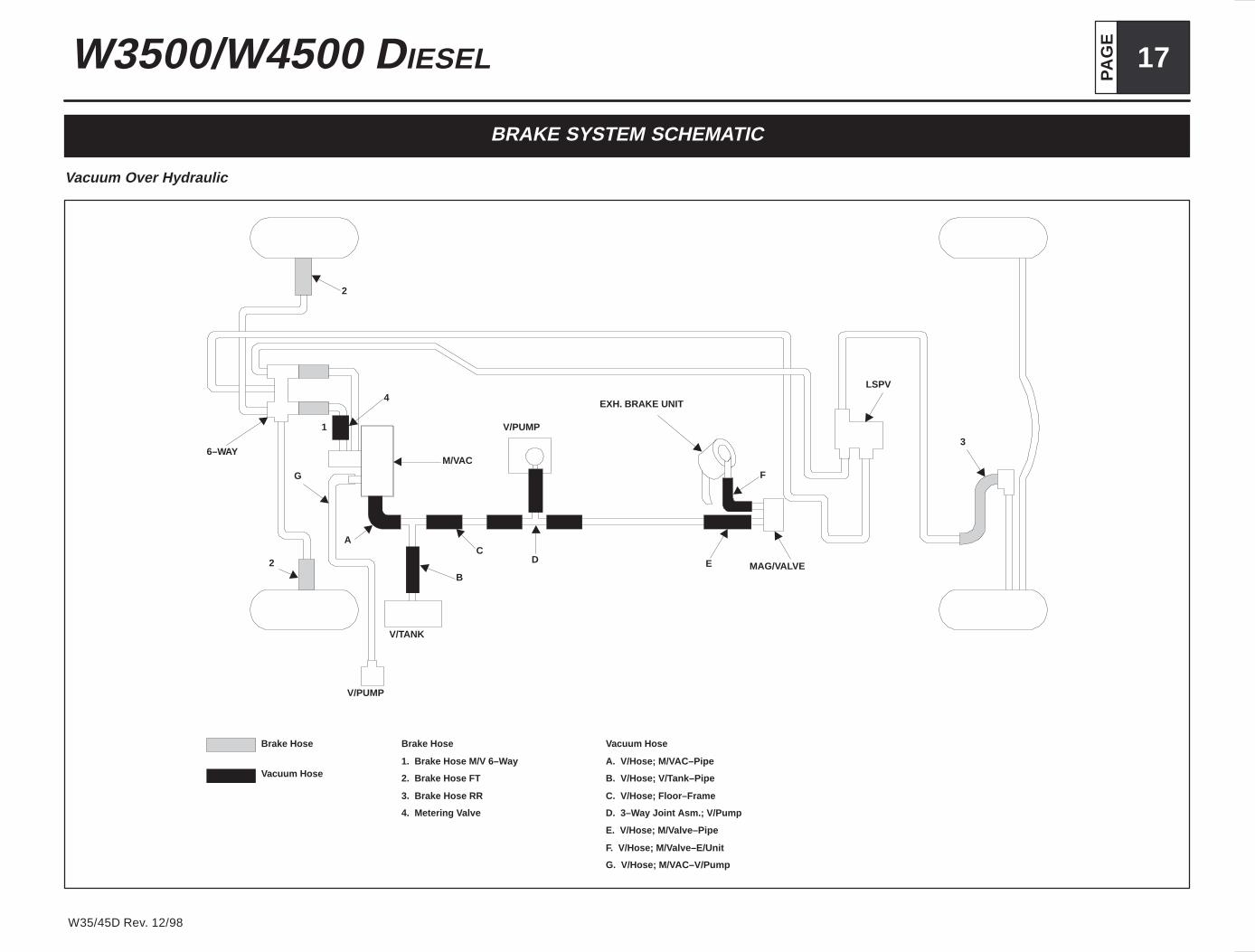
BRAKE SYSTEM SCHEMATIC
Vacuum Over Hydraulic
6–WAY
G
1
2
A
V/PUMP
V/TANK
B
CD E MAG/VALVE
V/PUMP
M/VAC
4EXH. BRAKE UNIT
F
LSPV
3
2
Brake Hose
Vacuum Hose
Brake Hose
1. Brake Hose M/V 6–W ay
2. Brake Hose FT
3. Brake Hose RR
4. Metering V alve
Vacuum Hose
A. V/Hose; M/V AC–Pipe
B. V/Hose; V/T ank–Pipe
C. V/Hose; Floor–Frame
D. 3–Way Joint Asm.; V/Pump
E. V/Hose; M/Valve–Pipe
F. V/Hose; M/Valve–E/Unit
G. V/Hose; M/VAC–V/Pump

PA
GE18 W3500/W4500 DIESEL
W35/45D Rev. 12/98
1999 MODEL DIESEL FUEL FILLER
Installation Instructions
1. Disconnect Battery
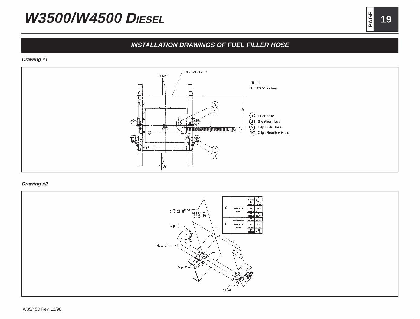
2. Take out hoses, clips, pipe joint support bracket (3), filler neck, fuel filler cap andprotective wrap from storage box. Mount support bracket on rail per drawing #1.Bracket location is at 20.55 inches.
3. Remove the temporary filler cap from the tank.
4. Install 90° hose (1) on the fuel tank neck. Secure with clip (9) hose lengths areset for 96 inch wide body to adjust for narrower body .See drawing #2.
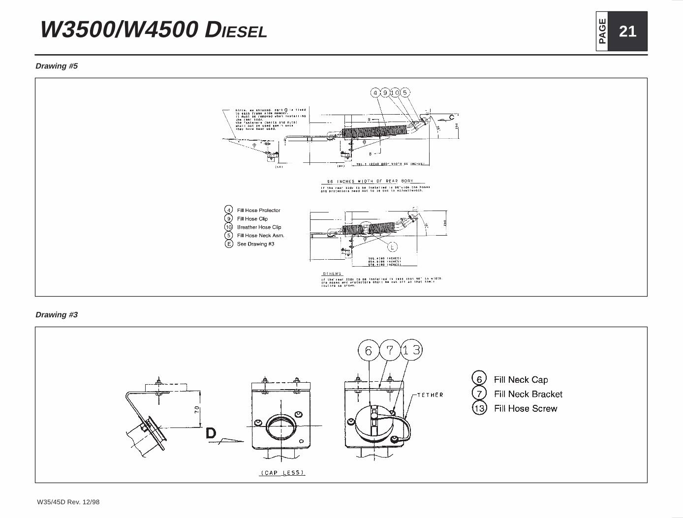
5. Place pipe joint (11) in open end of hose and clamp with clip (9). See drawing #3.
6. Place other piece of filler hose and vent hose tube through the protective wrapand join with 90° hose at the pipe joint use clips to secure hose.
7. Make sure the vent tube hose is placed on top of the filler hose inside the protec-tive wrap. This will allow the fuel tank to vent properly. The hose must be cov-ered with the protective wrap. See drawing #4.
8. Secure the fuel filler hose and fuel vent hose that is surrounded by the protectivewrap to the support bracket with two tie wraps. The filler neck must be mountedat 35° from the frame horizontal. See drawing #5.
9. Secure the filler plate to the bottom of the body.
10.Filler instructions for the gasoline fuel tank are the same as above except that thefiller neck plate is offset from the frame bracket due to the bend in the outer hosethat prevents fuel splash back. The different hose makes the attaching locationon the body different between the diesel and the gasoline tank. See drawing #1.
11. Secure cap and cap tether to the filler plate. See drawing #1.
12.Check for leaks.
13.Reconnect battery.
Number Part Name Part Number Quantity
1 Filler Hose 897108 251 001
2 Breather Hose 894462 403 001
3 Bracket: Filler Hose 897127 344 001
4 Protector: Filler Hose 897114 063 002
5 Neck Assembly: Filler Hose 897116 622 001
6 Cap: Filler Neck 897116 431 001
7 Bracket: Filler Neck 897116 621 001
8 Clip: Band/Protector 109707 107 002
9 Clip: Filler Hose 894435 876 004
10 Clip: Breather Hose 894242 034 002
11 Joint Pipe 121431 134 001
12 Bolt 02868 1035 002
13 Screw: Filler Hose 894381 646 003
PA
GE
19W3500/W4500 DIESEL
W35/45D Rev. 12/98
INSTALLATION DRAWINGS OF FUEL FILLER HOSE
Drawing #1
Drawing #2

PA
GE20 W3500/W4500 DIESEL
W35/45D Rev. 12/98
Drawing #3
Drawing #4
PA
GE
21W3500/W4500 DIESEL
W35/45D Rev. 12/98
Drawing #5
Drawing #3
PA
GE22 W3500/W4500 DIESEL
W35/45D Rev. 12/98
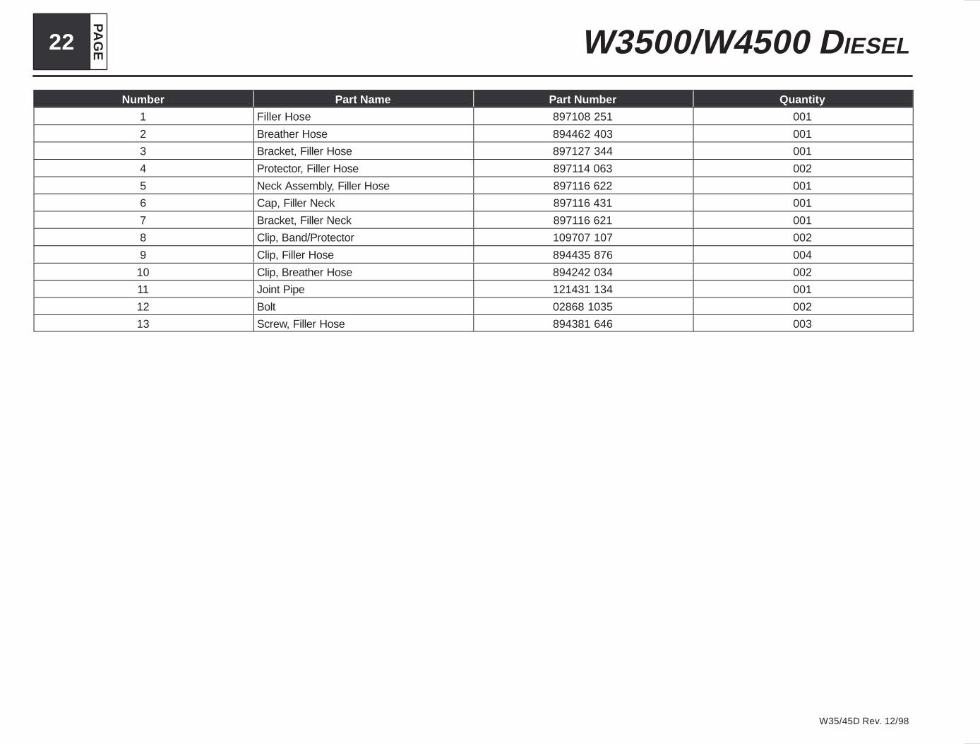
Number Part Name Part Number Quantity
1 Filler Hose 897108 251 001
2 Breather Hose 894462 403 001
3 Bracket, Filler Hose 897127 344 001
4 Protector, Filler Hose 897114 063 002
5 Neck Assembly, Filler Hose 897116 622 001
6 Cap, Filler Neck 897116 431 001
7 Bracket, Filler Neck 897116 621 001
8 Clip, Band/Protector 109707 107 002
9 Clip, Filler Hose 894435 876 004
10 Clip, Breather Hose 894242 034 002
11 Joint Pipe 121431 134 001
12 Bolt 02868 1035 002
13 Screw, Filler Hose 894381 646 003