Embed Size (px)
Citation preview

10 January,2002 Seminar of Master Thesis 1
Helsinki University of Technology
Department of Electrical and Communication Engineering
WCDMA Simulator with Smart Antennas
Hong Zhang
Communication laboratory
Supervisor: Professor Seppo J. Halme
Instructor: M. Sc. Adrian Boukalov

10 January,2002 Seminar of Master Thesis 2
Helsinki University of Technology
Department of Electrical and Communication Engineering
Outline
1. Background
2. Different approach in WCDMA system modelling
3. Spreading in WCDMA
4. RAKE Receiver and Multiuser Detection
5. Smart Antenna in WCDMA
6. Simulation Results
7. Conclusion

10 January,2002 Seminar of Master Thesis 3
Helsinki University of Technology
Department of Electrical and Communication Engineering
The goal of 3Gto provide a wide variety of communication
services and high speed data access.
The increasing demand of highcapacity
WCDMAradio access technology for 3G
To provide high capacity
SpreadingSmart antennaRAKE receiverMultiuser detection
Simulation
1. Background
technique
tool

10 January,2002 Seminar of Master Thesis 4
Helsinki University of Technology
Department of Electrical and Communication Engineering
2. Different approach inWCDMA system modelling (1)
CDMA System Modelling
Synchronous CDMA
Asynchronous CDMA
Modeling with single path
Modeling with multipath
Modeling with smart antenna
Modeling with AWGN channel
Modeling with channel fading
With linearalgebra knowledge
com
plex
ity
10 January,2002 Seminar of Master Thesis 5
Helsinki University of Technology
Department of Electrical and Communication Engineering
DOA
The tapped delay line model
T
0
T
1
T
N-1
Linear time-variant system (τ ,t)vmax τmax<<1
Quasi-stationary t(τ)Uncorrelated scatters
GWSSUS
Sampled
i(t)δ( τ - τi )
Tapped delay line
Ws τmax<<1
j(t) δ( τ - jT)
Narrowband model 0(t)
∑−
=
1
0
N
j
∑i
Ray tracing model
where j (t) is the complex amplitude, τj is path delay and j isDirection Of Arrival, a( - j) is the steering vectorGWSSUS: Gaussian Wide Sense Stationary Uncorrelated ScattersDOA: Direction Of Arrival
h (t, τ, ) = j (t)δ( τ - τj ) δ( - j)∑−
=
1
0
N
j
2. Different approach in WCDMA system modelling (2): Mobile radio channel
h (t, τ, ) = j (t)δ( τ - τj ) a( - j)∑−
=
1
0
N
j
Multiple antennas in the receiver
10 January,2002 Seminar of Master Thesis 6
Helsinki University of Technology
Department of Electrical and Communication Engineering
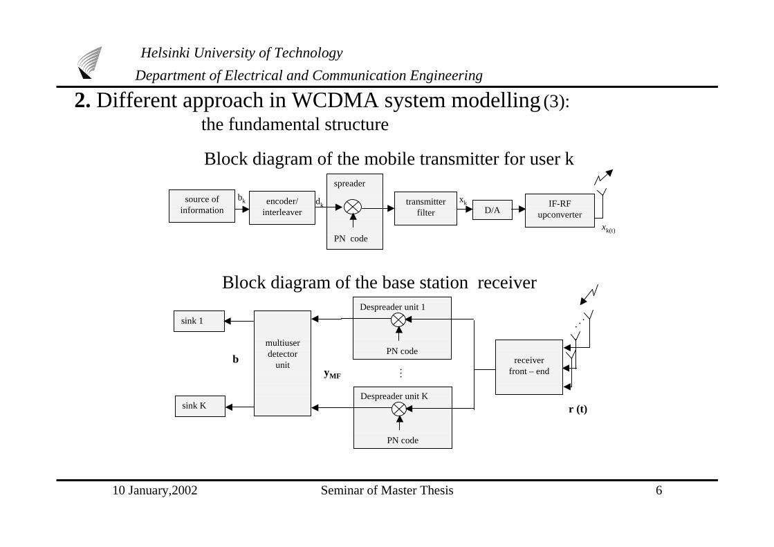
xkdkbk
spreader
PN code
source ofinformation
encoder/interleaver
transmitterfilter D/A
IF-RFupconverter
Block diagram of the mobile transmitter for user k
xk(t)
Block diagram of the base station receiver
receiverfront – end
multiuserdetector
unit
sink K
sink 1
Despreader unit 1
PN code
Despreader unit K
PN code
yMF
r (t)
bM
N
2. Different approach in WCDMA system modelling (3): the fundamental structure

10 January,2002 Seminar of Master Thesis 7
Helsinki University of Technology
Department of Electrical and Communication Engineering
Discrete time model base band uplinkmodel for asynchronous CDMA system
over a mobile radio channel
n
r
d1(i)s1(i)
u1 p c1,1(i) ... c1,M(i)
d2(i)s2(i) u1 p c2,1(i) ... c2,M(i)
dK(i)sK(i) u1 p cK,1(i) ... cK,M(i)
.
.
.
.
.
.
.
.
.
✦ The output after matchedfiltering and correlating
✦ The received signal
r = ∑−
=
1
0
L
i∑
=
K
k 1∑
=
M
m 1
)()(ˆ , idic kmk
−− NQiL
mk
iNQ
O
i
O
)1(
, )(s + n=SCd+n
y =C H SH S C d + C H SH n
Where )(ˆ , imks =
− mkMO
ikmk
O
,ˆ
)(ˆ,
τ
τs
)(idk : the ith data symbol transmitted by user k
)(ˆ iks : the zero-padded spreading sequence for symbols generated by user k
)(ˆ , ic mk : the channel coefficients over the mth multipath for the ith symbol generated by user k.
L : the total amount of the data symbol sent by every active userK : the total amount of active users sending data to the BTS
M : the maximum delay spread normalised to sampling intervalM : the amount of resolvable multipath components per user data sequenceC: channel matrixS: the matrix of received spreading waveformn: Additive White Gaussian Noise
2. Different approach in WCDMA system modelling (4): Discrete time base band uplink model for asynchronous CDMA

10 January,2002 Seminar of Master Thesis 8
Helsinki University of Technology
Department of Electrical and Communication Engineering
= λ
θπ cos2 d
✦ The received signal
y = HC0HSH r = HC0
HSH S &0 d + HC0HSH n
✦ The output after matched filteringand correlating
✦ The phase difference of the receivedsignal between adjacent antenna elements The ULA with the direction of arrival
( , ) indicated
d B
waveform
z
x
y
B-1
1
D’
r = S �& 0 d +n
where �LV�WKH�VWHHULQJ�PDWUL[
2. Different approach in WCDMA system modelling (5): Discrete time base band uplink model for asynchronous CDMA with smart antenna
10 January,2002 Seminar of Master Thesis 9
Helsinki University of Technology
Department of Electrical and Communication Engineering
3. Spreading in WCDMA (1)
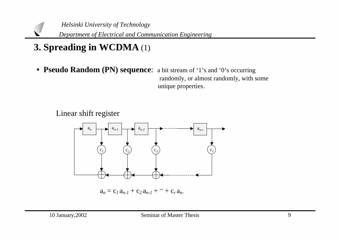
an an-1 an-2 an-r
c1 c2 c3 cr
an = c1 an-1 + c2 an-1 + ... + cr an-
Linear shift register
• Pseudo Random (PN) sequence: a bit stream of ‘1’s and ‘0’s occurring randomly, or almost randomly, with some unique properties.

10 January,2002 Seminar of Master Thesis 10
Helsinki University of Technology
Department of Electrical and Communication Engineering
Spreading: to multiply the input information bits by a PN code and get processing gain, the chip level signal’s bandwidth is much wider than that of input information bits. It maintains the orthogonality among different physical channels of each user.
Scrambling: to separate the signals from the different users. It doesn’t change the signal bandwidth. Each user has a unique scrambling code in the system.
• Uplink spreading and modulation
bit rate chip rate
P(t)
Channelization codes (Walsh/OVSF)
(Cd )DPDCH
j
Channelization codes
(Walsh/OVSF) (Cc)
DPCCH
Scramblingcodes
(Csc)
P(t)
cos ( t)
sin ( t)
(Gold)
chip rate
WCDMAan interference limited system
Selecting codeshigh autocorrelation low cross correlation
Suppressing interference
3. Spreading in WCDMA (2) : Spreading and scrambling at the uplink
10 January,2002 Seminar of Master Thesis 11
Helsinki University of Technology
Department of Electrical and Communication Engineering
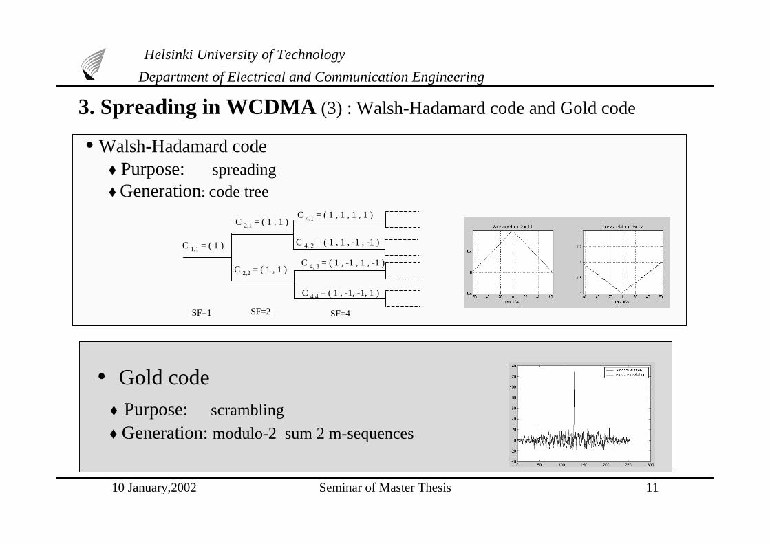
C 1,1 = ( 1 )
C 2,2 = ( 1 , 1 )
C 2,1 = ( 1 , 1 )
C 4, 2 = ( 1 , 1 , -1 , -1 )
C 4,1 = ( 1 , 1 , 1 , 1 )
C 4, 3 = ( 1 , -1 , 1 , -1 )
C 4,4 = ( 1 , -1, -1, 1 )
SF=1 SF=2 SF=4
• Walsh-Hadamard code ♦ Purpose: spreading ♦ Generation: code tree
• Gold code
♦ Purpose: scrambling
♦ Generation: modulo-2 sum 2 m-sequences
3. Spreading in WCDMA (3) : Walsh-Hadamard code and Gold code
10 January,2002 Seminar of Master Thesis 12
Helsinki University of Technology
Department of Electrical and Communication Engineering
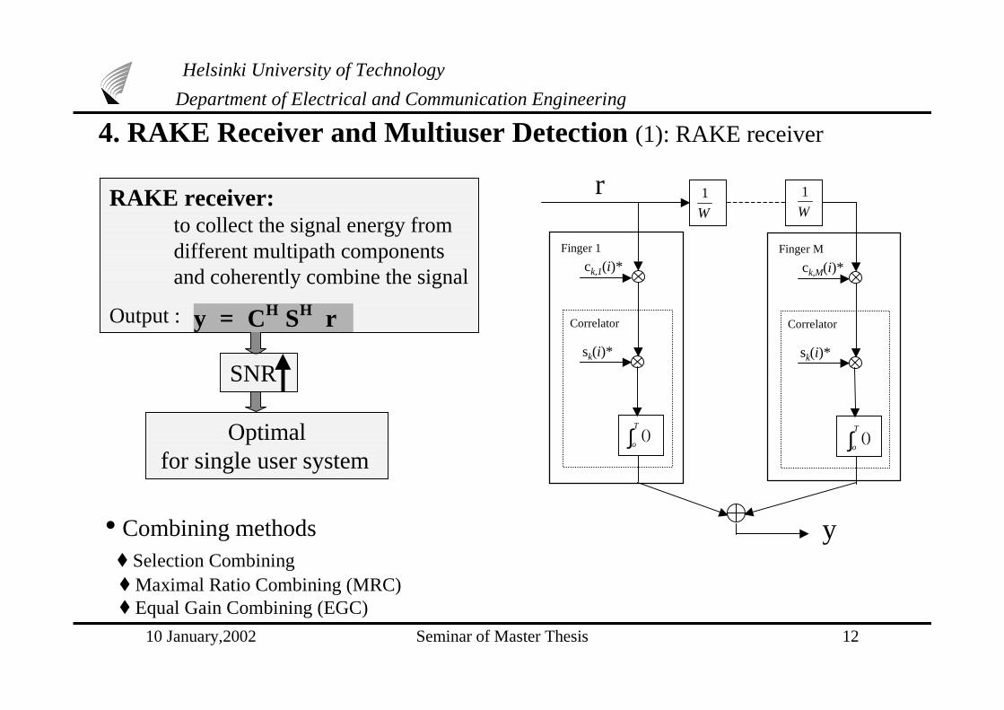
4. RAKE Receiver and Multiuser Detection (1): RAKE receiver
r
ck,1(i)*
Correlator
sk(i)*
Finger 1
ck,M(i)*
Correlator
sk(i)*
Finger M
y
W
1W
1
∫T
o() ∫
T
o()
• Combining methods ♦ Selection Combining ♦ Maximal Ratio Combining (MRC) ♦ Equal Gain Combining (EGC)
RAKE receiver: to collect the signal energy from different multipath components and coherently combine the signal
Output :
SNR
Optimal for single user system
y = CH SH r
10 January,2002 Seminar of Master Thesis 13
Helsinki University of Technology
Department of Electrical and Communication Engineering
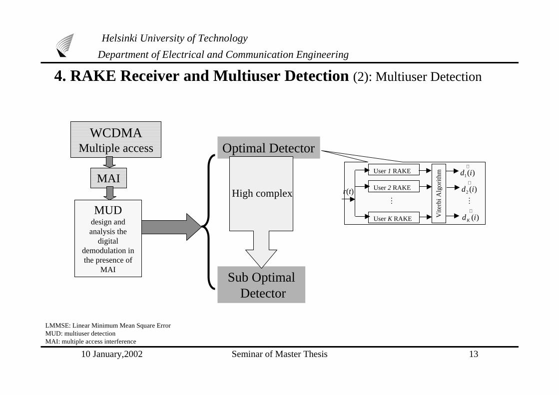
Optimal DetectorWCDMA
Multiple access
MAI
MUDdesign andanalysis the
digitaldemodulation inthe presence of
MAI
User 1 RAKE
User 2 RAKE
User K RAKE Vite
rbi A
lgor
ithm
r(t)
∧)(1 id
∧)(2 id
∧)(idK
MM
Sub Optimal Detector
LMMSE: Linear Minimum Mean Square ErrorMUD: multiuser detectionMAI: multiple access interference
High complex
4. RAKE Receiver and Multiuser Detection (2): Multiuser Detection

10 January,2002 Seminar of Master Thesis 14
Helsinki University of Technology
Department of Electrical and Communication Engineering
Decorrelating Detector
SubOptimal Detector
Decorrelating detector for 2 synchronous users
r(t)s1(t)
s2(t)
y1
y2
+-
-+∫
T
0
ρ
∧)(1 id
∧)(2 id
∫T
0
∫T
0
(synchronous)
(asynchronous)
Decd = [RT [1] z + R [0] + R [1] z-1 ]-1 y
Decd = R-1y
LMMSE
LMMSE: Linear MinimumMean Square ErrorMUD: multiuser detectionMAI: multiple accessinterference
(synchronous)
(asynchronous)
Decd = (R+ 2I)-1 y
Decd = (RT [1] z + R [0] + R [1] z -1 + 2I )-1 y
Noise
4. RAKE Receiver and Multiuser Detection (3): Multiuser Detection
Varying channel
Adaptive MMSE algorithm-RLS algorithm with adaptive memory
J(k) = ∑=
−n
i
in
1
λ (| �N�_2 )

10 January,2002 Seminar of Master Thesis 15
Helsinki University of Technology
Department of Electrical and Communication Engineering
5. Smart Antenna in WCDMA (1)
Desired signal
Interfering signal
• switched beam antenna array
Smart Antenna consists of antenna array, combined with signal processing in space (or time) domain
Desired signal
Interfering signal
• adaptive antenna arrayType
Broad-band beam-former structure
Reference signal
Weightcontrol
Errorsignal
y(t)
T1 ( i, i)r1
T
w11 w12 w1M
TB ( i, i)rB
T
wB1 wB2 wBM
Steering Delay
-
+
M
y(t) = ∑=
B
n 1
wn rn (t)

10 January,2002 Seminar of Master Thesis 16
Helsinki University of Technology
Department of Electrical and Communication Engineering
ConventionalBeamforming
StatisticallyOptimum
Beamforming
AdaptiveBeamforming
RLS algorithmwith adaptivememory
wc = (1 /B ) s
MMSE w = R-1 p
Max SNR Rn-1Rs w = max w
LCMV w = R-1c[cHR-1c]-1g
G(k) =)()1()(1
)()1(1
1
krkPkr
krkPH −+
−−
−
λλ
�N��� �G�N� - w H (k-1) r(k)
w(k)= w (k-1) + G(k) *(k)
P(k) = -1 P(k-1) - -1 G(k) rH (k) P(k-1)
�N� � �N���� �5H> )1(ˆ −kHψ r(k) *(k)]]−+
λλ
S(k) = -1[I - G(k) rH (k)] S(k-1) [I - r (k)GH(k)]+ -1 G(k) GH(k)- -1 P(k)
)(kψ = [I - G(k) rH (k)] )1(ˆ −kHψ + S(k) r(k) *(k)
MMSE: mimimize mean square errorLCMV: Linearly Constrained Minimum Variance RLS: recursive least squares
5. Smart Antenna in WCDMA (2): Beamforming schemes
10 January,2002 Seminar of Master Thesis 17
Helsinki University of Technology
Department of Electrical and Communication Engineering
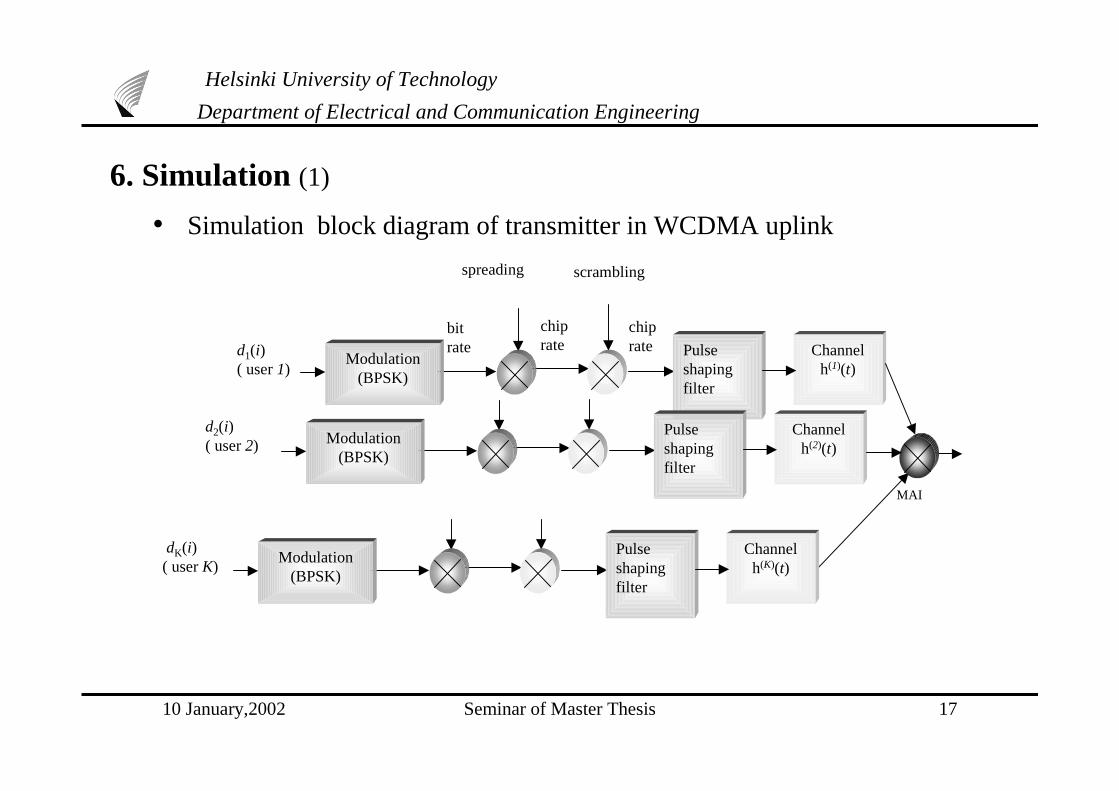
6. Simulation (1)
• Simulation block diagram of transmitter in WCDMA uplink
spreading scrambling
bitrate
chiprate
chiprate
Modulation(BPSK)
Pulseshapingfilter
Channelh(1)(t)
dK(i)( user K)
MAI
d2(i)( user 2) Modulation
(BPSK)
Pulseshapingfilter
Channelh(2)(t)
Modulation(BPSK)
Pulseshapingfilter
Channelh(K)(t)
d1(i)( user 1)

10 January,2002 Seminar of Master Thesis 18
6. Simulation (2)
• Simulation block diagram of 2- D RAKE receiver in uplink WCDMA
User K
User 1 Spatial processing Temporal processing (RAKE)
Multiuser
Detection
W1,M
W1,2
n(t)
%
%
%%
%
%
%
%
W1,1
%
%%
%*1(t- M)
*1(t- 2)
*1(t- 1)
WK,M
WK,2%
%
%
%
%
WK,1
%
%%
%*1(t- M)
*1(t- 2)
*K(t- 1)
∫T
o()
∫T
o()
∫T
o()
∫T
o()
∫T
o()
∫T
o()
∧)(1 id
∧)(idK
Helsinki University of Technology
Department of Electrical and Communication Engineering
c~
c~
N
M M
M
N
N
10 January,2002 Seminar of Master Thesis 19
Helsinki University of Technology
Department of Electrical and Communication Engineering
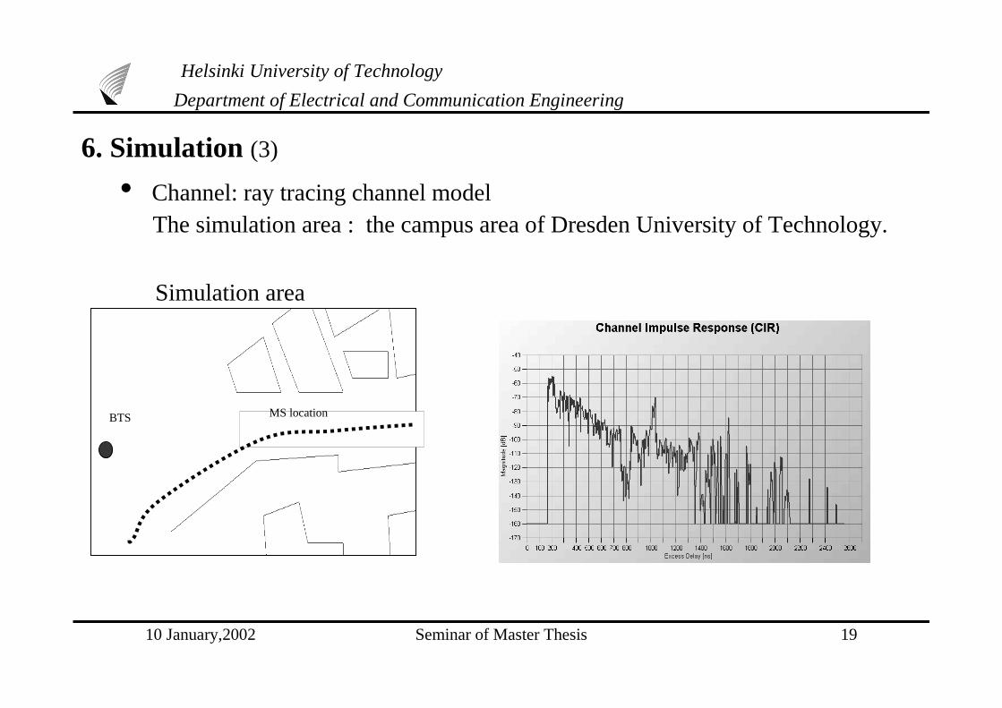
6. Simulation (3)
• Channel: ray tracing channel model The simulation area : the campus area of Dresden University of Technology.
Simulation area
BTS MS location

10 January,2002 Seminar of Master Thesis 20
Helsinki University of Technology
Department of Electrical and Communication Engineering
6. Simulation Results(4)
• Assume all the users randomly access the channel, and the PN code of each user is acquiredand synchronized perfectly in the base station.
• Assume the number of fingers in RAKE receiver equal to the number of multipathcomponents.
• The channel parameters are updated symbol by symbol, i.e. channel varies with time.
The system performance of1-D RAKE and conventional
matched filter receiver forsingle user
System performance of 1- D RAKEreceiver with Decorrelating Detector
and linear MMSE
DD: Decorrelating Detector LMMSESA: smart antenna for spatial processing PG: Processing GainMUD: Multiuser Detection
10 January,2002 Seminar of Master Thesis 21
0 10 20 30 40 50 60 70 80
10-2
10-1
100
Sys tem performance
S NR (dB)
BE
RConventionalRakeSA RAKESA RAKE adaptive MUD(RLS)
Helsinki University of Technology
Department of Electrical and Communication Engineering
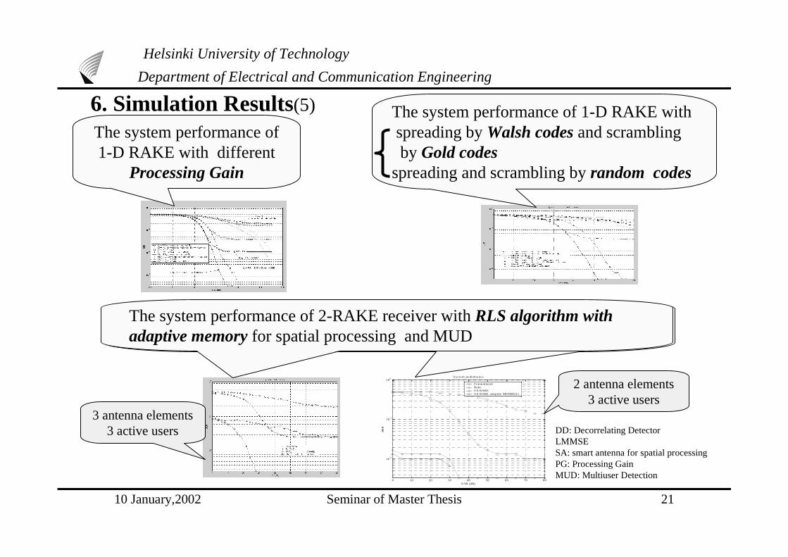
6. Simulation Results(5)
3 antenna elements3 active users
2 antenna elements3 active users
The system performance of1-D RAKE with different
Processing Gain
The system performance of 1-D RAKE with spreading by Walsh codes and scrambling by Gold codesspreading and scrambling by random codes
The system performance of 2-RAKE receiver with RLS algorithm withadaptive memory for spatial processing and MUD
DD: Decorrelating Detector LMMSESA: smart antenna for spatial processing PG: Processing GainMUD: Multiuser Detection

10 January,2002 Seminar of Master Thesis 22
Helsinki University of Technology
Department of Electrical and Communication Engineering
7. Conclusion
• The simulation results have shown that spreading, RAKE receiver, multiuser detection and smart antenna are very important techniques to improve WCDMA system performance and increase system capacity.