Embed Size (px)
Citation preview
VROOM: Virtual ROuters On the Move
Yi Wang (Princeton)
With: Eric Keller (Princeton)Brian Biskeborn (Princeton)
Kobus van der Merwe (AT&T Labs - Research) Jennifer Rexford (Princeton)
2
Key idea Routers should be free to roam around
Useful for many different applications Simplify network maintenance Simplify service deployment and evolution Reduce power consumption …
Feasible in practice No performance impact on data traffic No visible impact on routing protocols
Virtual ROuters On the Move (VROOM)
3
VROOM: The Basic Idea
1
2 3
4
5
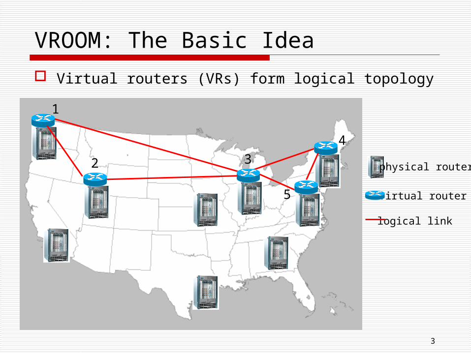
Virtual routers (VRs) form logical topology
physical router
virtual router
logical link
4
VROOM: The Basic Idea
1
2 3
4
5
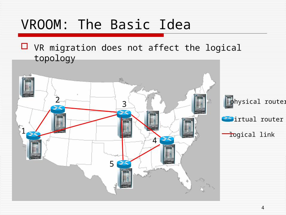
VR migration does not affect the logical topology
physical router
virtual router
logical link
The Rest of the Talk is Q&A
Why is VROOM a good idea? What are the challenges?
Or it is just technically trivial?
How does VROOM work? The migration process
Is VROOM practical? Prototype system Performance evaluation
Where to migrate? The scheduling problem
Still have questions? Feel free to ask!
5
6
The Coupling of Logical and Physical
Today, the physical and logical configurations of a router is tightly coupled
Physical changes break protocol adjacencies, disrupt traffic
Logical configuration as a tool to reduce the disruption E.g., the “cost-out/cost-in” of IGP link weights Cannot eliminate the disruption Account for over 73% of network maintenance events
7
VROOM Separates the Logical and Physical
Make a logical router instance migratable among physical nodes
All logical configurations/states remain the same before/after the migration IP addresses remain the same Routing protocol configurations remain the
same Routing-protocol adjacencies stay up
No protocol (BGP/IGP) reconvergence
Network topology stays intact
No disruption to data traffic
8
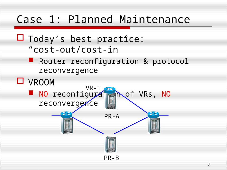
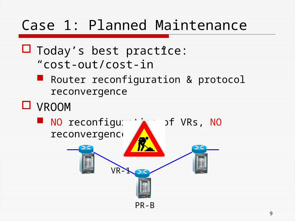
Case 1: Planned Maintenance
Today’s best practice: “cost-out/cost-in” Router reconfiguration & protocol
reconvergence
VROOM NO reconfiguration of VRs, NO reconvergence
PR-A
PR-B
VR-1
9
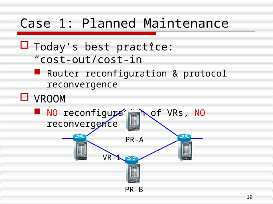
Case 1: Planned Maintenance
Today’s best practice: “cost-out/cost-in” Router reconfiguration & protocol
reconvergence
VROOM NO reconfiguration of VRs, NO reconvergence
PR-A
PR-B
VR-1
10
Case 1: Planned Maintenance
Today’s best practice: “cost-out/cost-in” Router reconfiguration & protocol
reconvergence
VROOM NO reconfiguration of VRs, NO reconvergence
PR-A
PR-B
VR-1
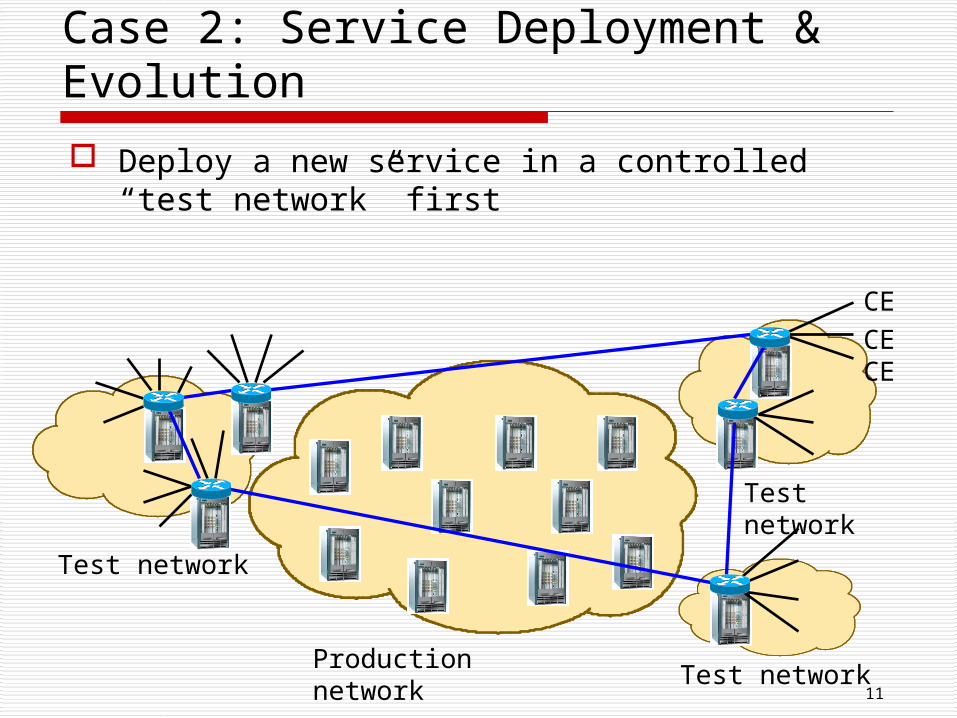
Deploy a new service in a controlled “test network” first
11
Case 2: Service Deployment & Evolution
Production network
Test network
Test network
Test network
CECECE
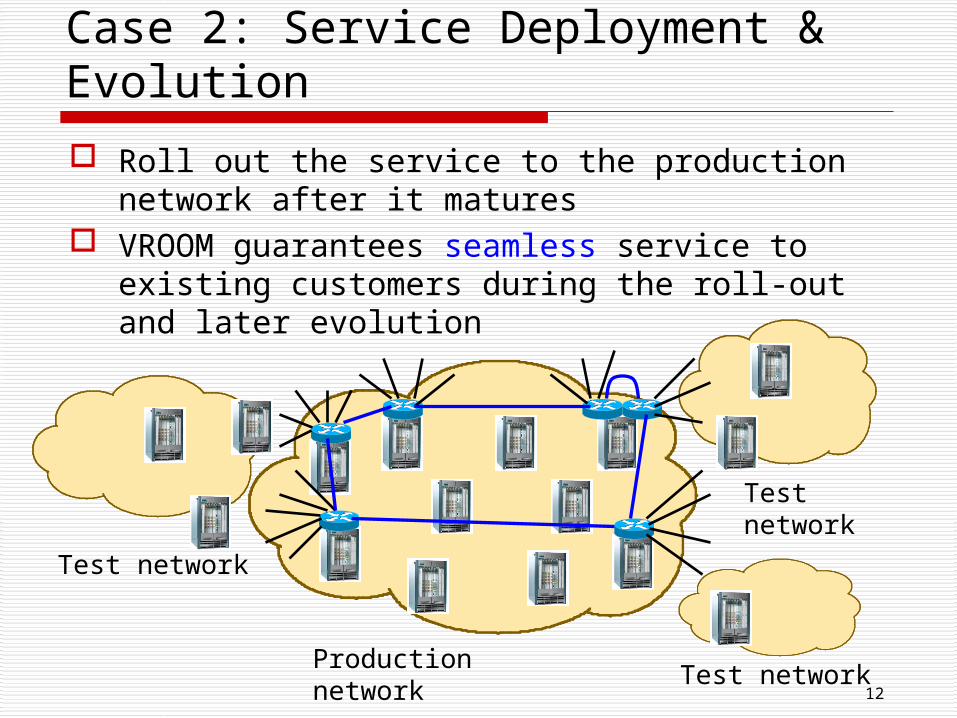
Roll out the service to the production network after it matures
VROOM guarantees seamless service to existing customers during the roll-out and later evolution
12
Case 2: Service Deployment & Evolution
Production network
Test network
Test network
Test network
13
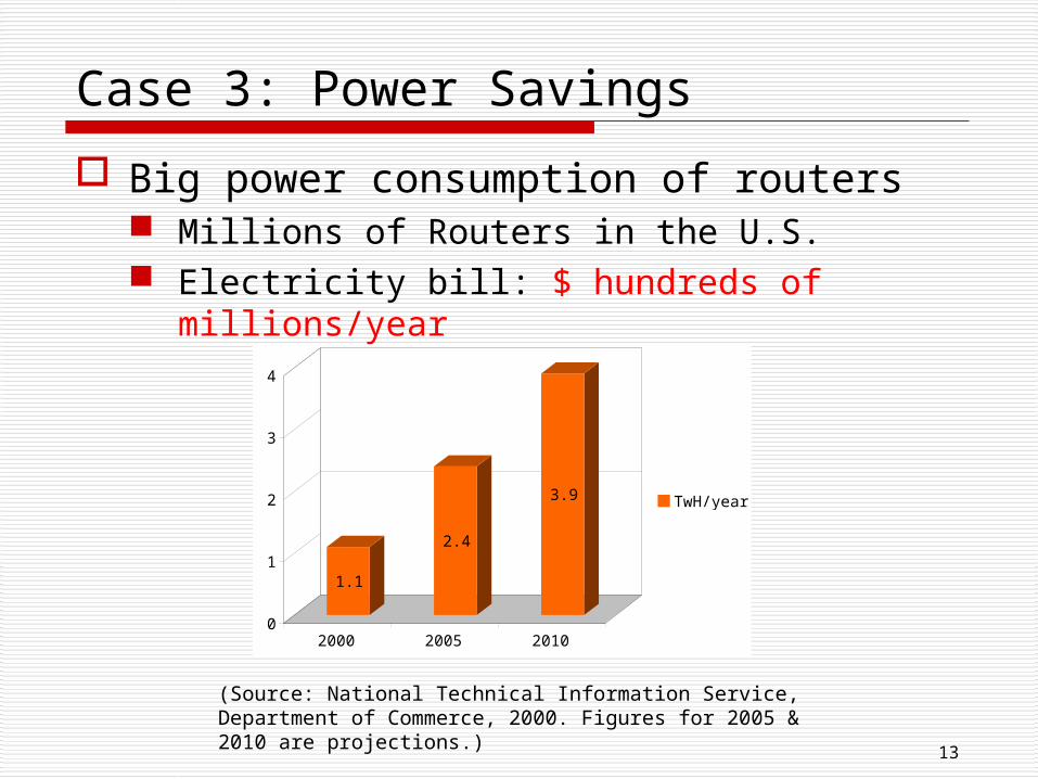
Case 3: Power Savings
Big power consumption of routers Millions of Routers in the U.S. Electricity bill: $ hundreds of millions/year
(Source: National Technical Information Service, Department of Commerce, 2000. Figures for 2005 & 2010 are projections.)
1.1
2.4
3.9
0
1
2
3
4
2000 2005 2010
TwH/year
14
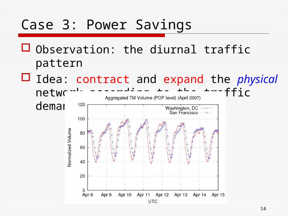
Case 3: Power Savings
Observation: the diurnal traffic pattern Idea: contract and expand the physical
network according to the traffic demand
15
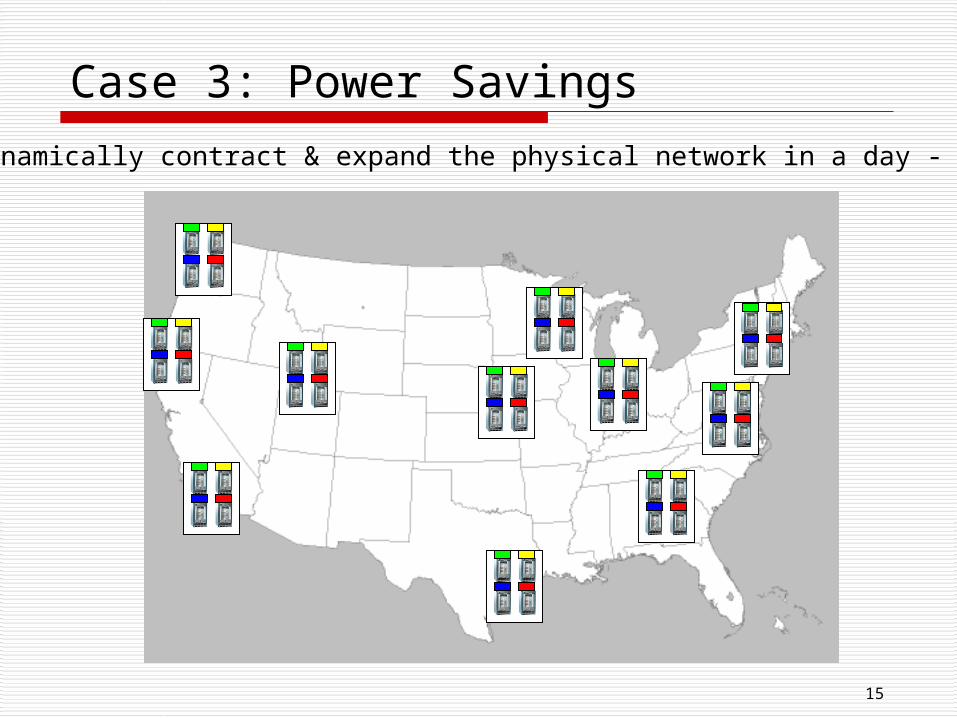
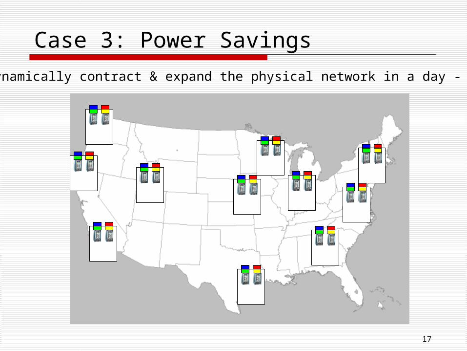
Case 3: Power Savings
Dynamically contract & expand the physical network in a day - 3PM
16
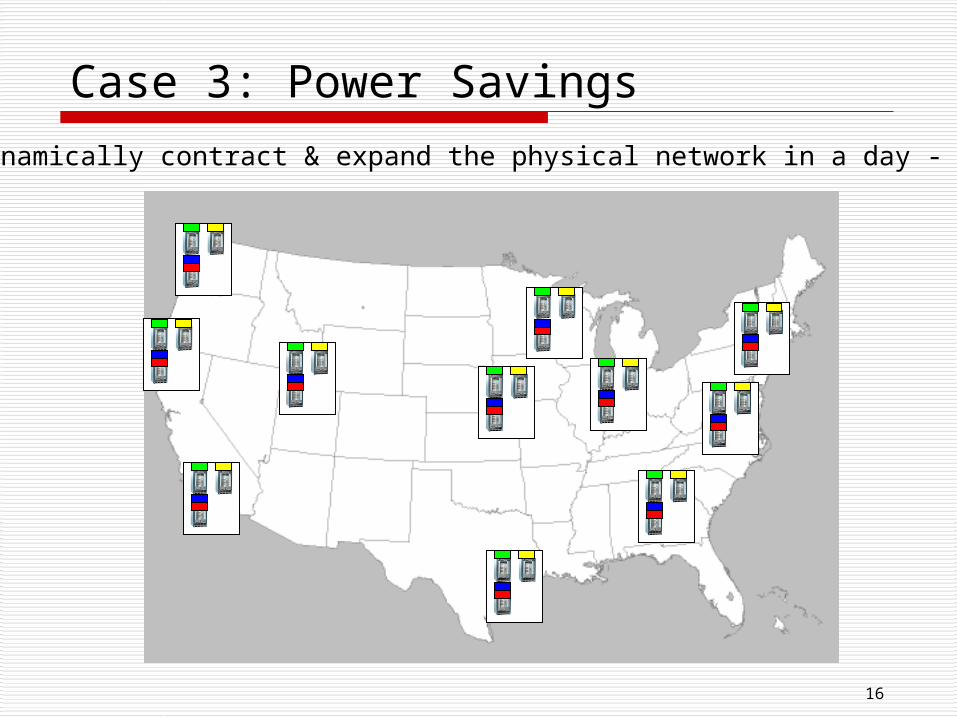
Case 3: Power Savings
Dynamically contract & expand the physical network in a day - 9PM
17
Case 3: Power Savings
Dynamically contract & expand the physical network in a day - 4AM
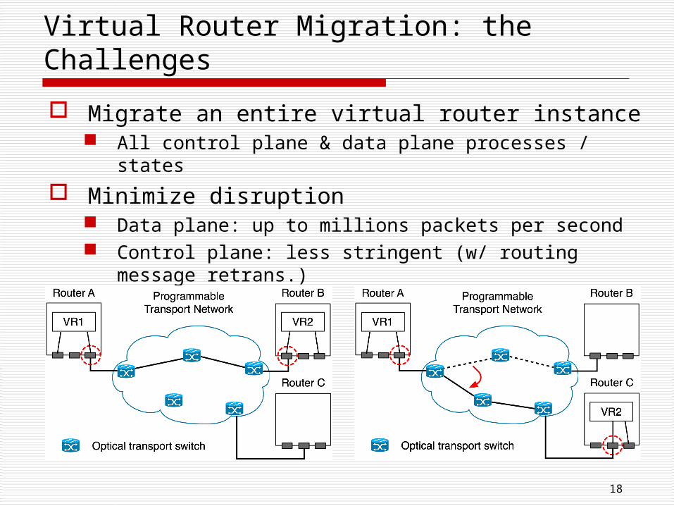
Migrate an entire virtual router instance All control plane & data plane processes / states
Minimize disruption Data plane: up to millions packets per second Control plane: less stringent (w/ routing message
retrans.)
Migrate links
18
Virtual Router Migration: the Challenges
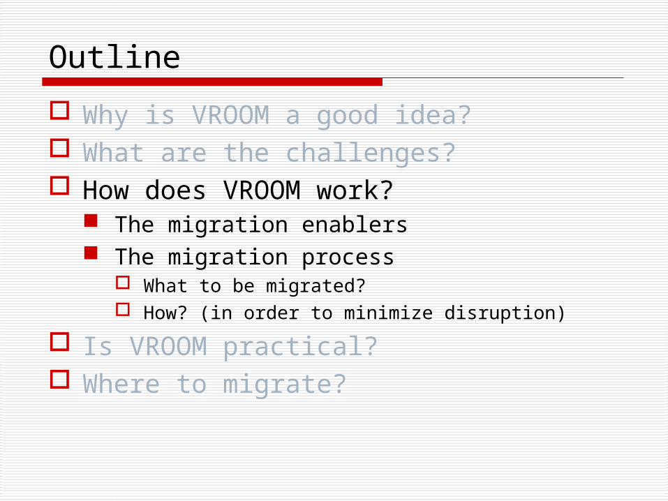
Outline
Why is VROOM a good idea? What are the challenges? How does VROOM work?
The migration enablers The migration process
What to be migrated? How? (in order to minimize disruption)
Is VROOM practical? Where to migrate?
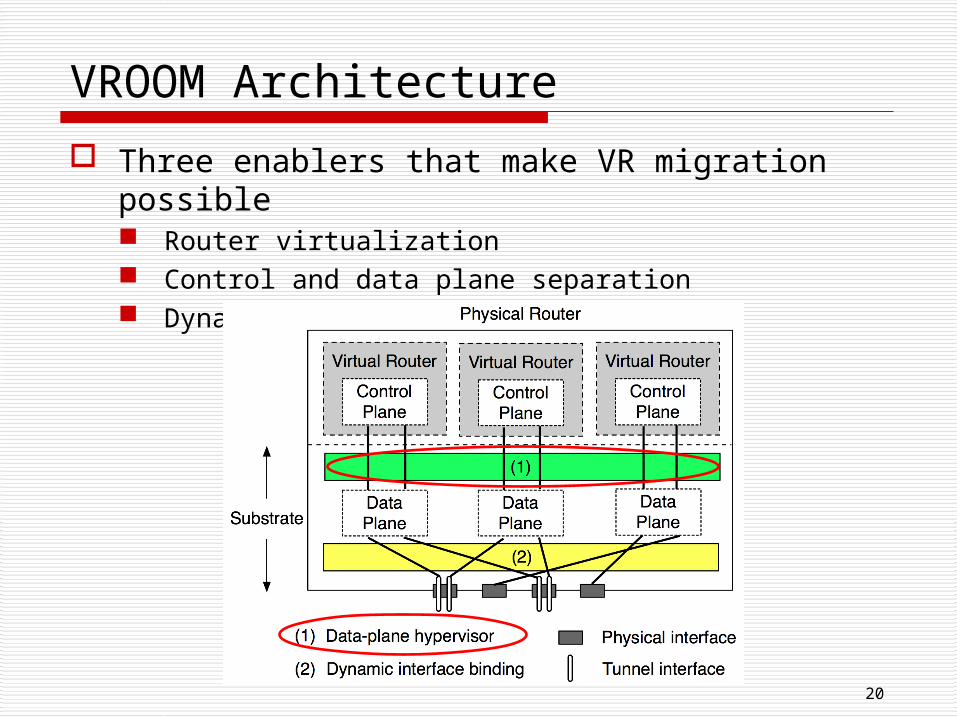
Three enablers that make VR migration possible Router virtualization Control and data plane separation Dynamic interface binding
20
VROOM Architecture
21
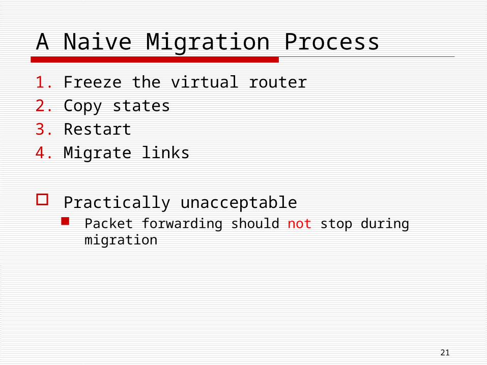
A Naive Migration Process
1. Freeze the virtual router2. Copy states3. Restart4. Migrate links
Practically unacceptable Packet forwarding should not stop during migration
22
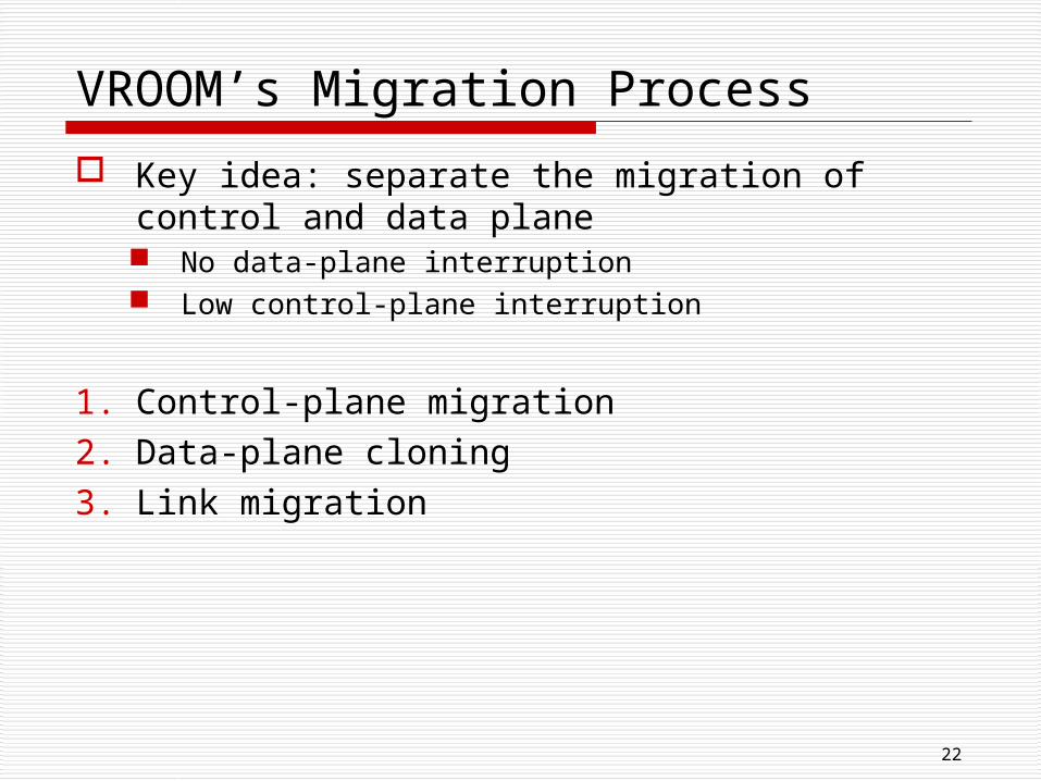
VROOM’s Migration Process
Key idea: separate the migration of control and data plane No data-plane interruption Low control-plane interruption
1. Control-plane migration2. Data-plane cloning3. Link migration
23
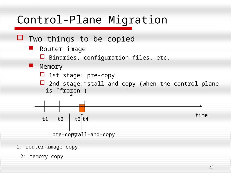
Control-Plane Migration
Two things to be copied Router image
Binaries, configuration files, etc. Memory
1st stage: pre-copy 2nd stage: stall-and-copy (when the control plane is
“frozen”)
t1 t2 t3 t4time
1 2
1: router-image copy
2: memory copy
pre-copy stall-and-copy
24
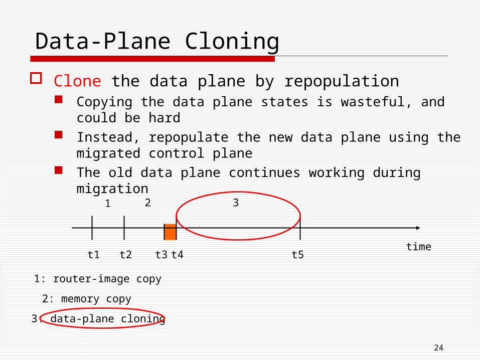
Data-Plane Cloning
Clone the data plane by repopulation Copying the data plane states is wasteful, and could be
hard Instead, repopulate the new data plane using the
migrated control plane The old data plane continues working during migration
t1 t2 t3 t4time
1 2
1: router-image copy
2: memory copy
t5
3
3: data-plane cloning
25
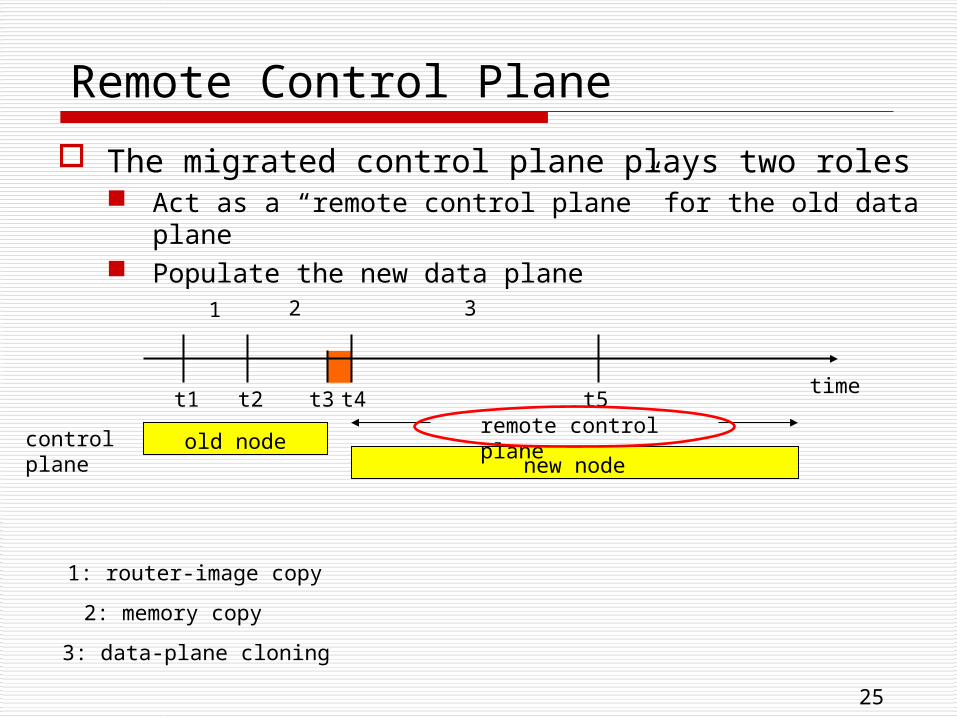
Remote Control Plane
The migrated control plane plays two roles Act as a “remote control plane” for the old data plane Populate the new data plane
t1 t2 t3 t4time
1 2
1: router-image copy
2: memory copy
t5
3
3: data-plane cloning
old nodenew node
control plane
remote control plane
26
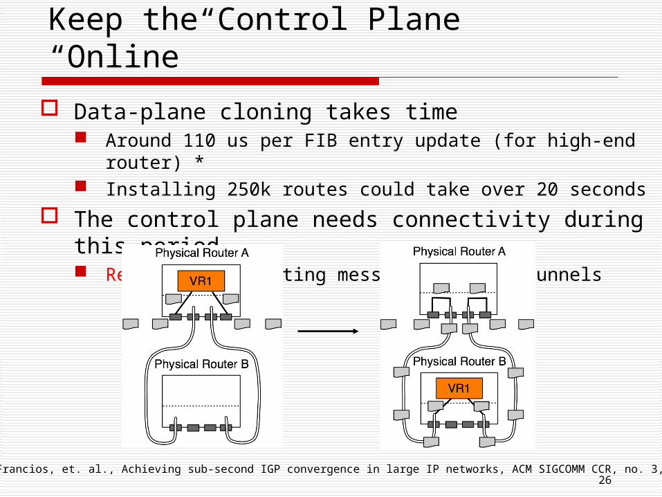
Keep the Control Plane “Online”
Data-plane cloning takes time Around 110 us per FIB entry update (for high-end router) * Installing 250k routes could take over 20 seconds
The control plane needs connectivity during this period Redirect the routing messages through tunnels
*: P. Francios, et. al., Achieving sub-second IGP convergence in large IP networks, ACM SIGCOMM CCR, no. 3, 2005.
27
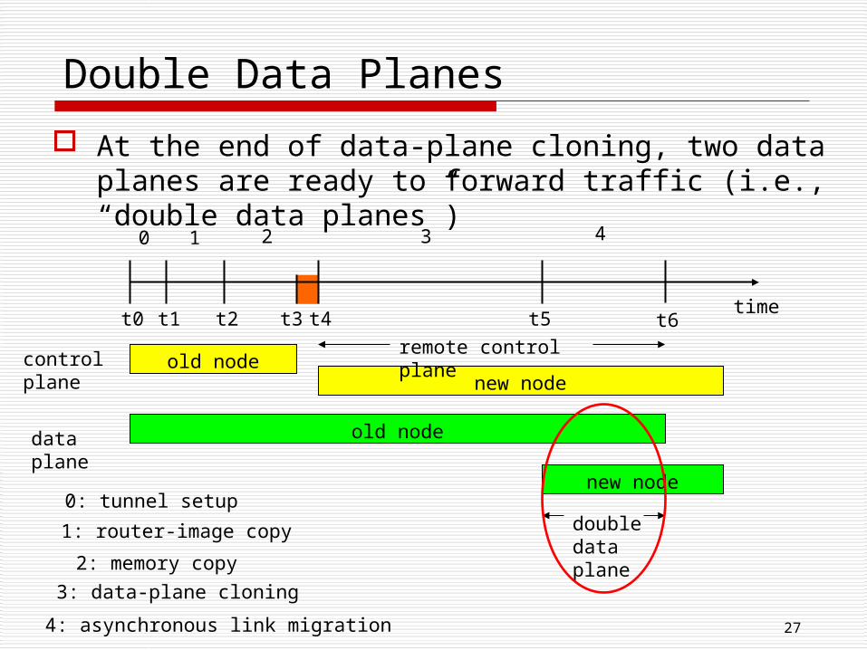
Double Data Planes
At the end of data-plane cloning, two data planes are ready to forward traffic (i.e., “double data planes”)
t1 t2 t3 t4time
1 2
1: router-image copy
2: memory copy
t5
3
3: data-plane cloning
t0
0
0: tunnel setupdoubledata plane
data plane
old node
4
4: asynchronous link migration
new node
old nodenew node
control plane
remote control planet6
28
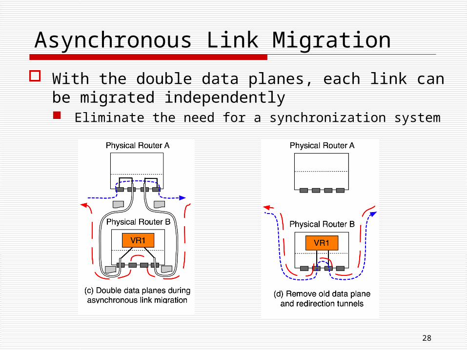
Asynchronous Link Migration
With the double data planes, each link can be migrated independently Eliminate the need for a synchronization system
Outline
Why is VROOM a good idea? What are the challenges? How does VROOM work? Is VROOM practical?
Prototype system Performance evaluation
Where to migrate?
30
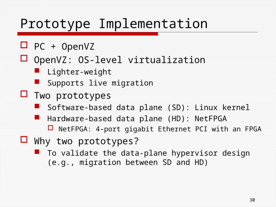
Prototype Implementation
PC + OpenVZ OpenVZ: OS-level virtualization
Lighter-weight Supports live migration
Two prototypes Software-based data plane (SD): Linux kernel Hardware-based data plane (HD): NetFPGA
NetFPGA: 4-port gigabit Ethernet PCI with an FPGA
Why two prototypes? To validate the data-plane hypervisor design (e.g.,
migration between SD and HD)
31
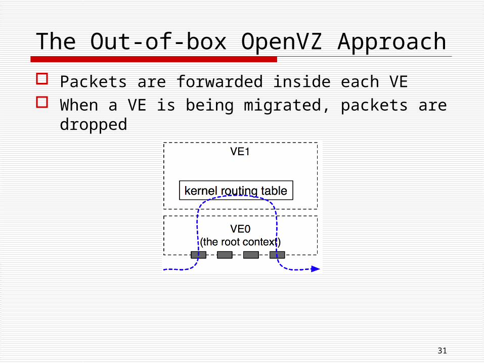
The Out-of-box OpenVZ Approach
Packets are forwarded inside each VE When a VE is being migrated, packets are
dropped
32
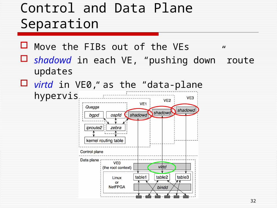
Control and Data Plane Separation
Move the FIBs out of the VEs shadowd in each VE, “pushing down” route
updates virtd in VE0, as the “data-plane hypervisor”
33
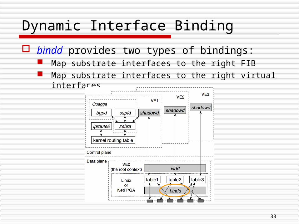
Dynamic Interface Binding
bindd provides two types of bindings: Map substrate interfaces to the right FIB Map substrate interfaces to the right virtual
interfaces
34
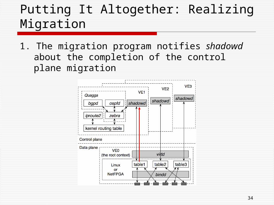
Putting It Altogether: Realizing Migration
1. The migration program notifies shadowd about the completion of the control plane migration
35
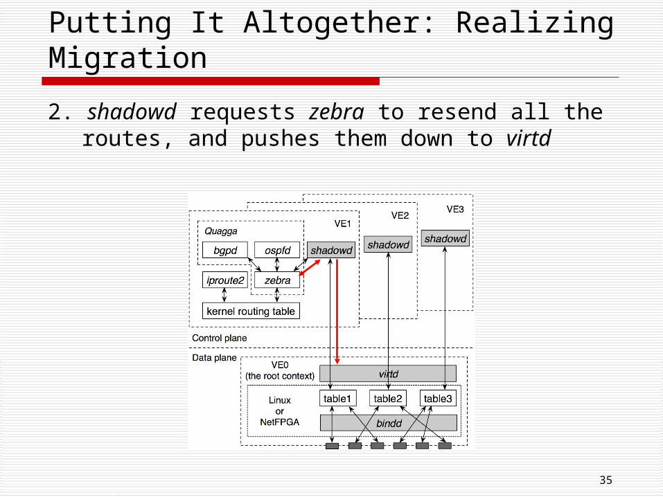
Putting It Altogether: Realizing Migration
2. shadowd requests zebra to resend all the routes, and pushes them down to virtd
36
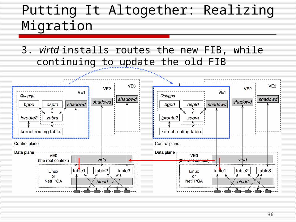
Putting It Altogether: Realizing Migration
3. virtd installs routes the new FIB, while continuing to update the old FIB
37
Putting It Altogether: Realizing Migration
4. virtd notifies the migration program to start link migration after finishing populating the new FIB
5. After link migration is completed, the migration program notifies virtd to stop updating the old FIB
38
Evaluation
Answer three questions Performance of individual migration steps? Impact on data traffic? Impact on routing protocol?
Experiments on Emulab

39
Performance of Migration Steps
Memory copy time With different
numbers of routes (dump file sizes)
0
1
2
3
4
5
6
0 10k 100k 200k 300k 400k 500k
Number of routes
Time (seconds)
Suspend + dump Copy dump file Undump + resume Bridging setup

40
Performance of Migration Steps
FIB population time Grows linearly w.r.t. the number of route entries Installing a FIB entry into NetFPGA: 7.4 microseconds Installing a FIB entry into Linux kernel: 1.94
milliseconds
• FIB update time: time for virtd to install entries to FIB• Total time: FIB update time + time for shadowd to send routes to virtd

41
Data Plane Impact
The diamond testbed
64-byte UDP packets, round-trip traffic

42
Data Plane Impact
HD router with separate migration bandwidth No delay increase or packet loss
SD router with separate migration bandwidth Up to 3.7% delay increase at 5k packets/s Less than 0.4% delay increase at 25k packets/s
SD, 5k packets/s

43
The Importance of Separate Migration Bandwidth
The dumbbell testbed
250k routes in the RIB

44
Separate Migration Bandwidth is Important
Throughput of the migration traffic

45
Separate Migration Bandwidth is Important
Delay increase of the data traffic

46
Separate Migration Bandwidth is Important
Loss rate of the data traffic

47
Control Plane Impact
The Abilene testbed
Assume a backbone running MPLS VR5 configured as
Core router (running OSPF only) Edge router (running OSPF + BGP)

48
Core Router Migration
No events during migration Average control plane downtime: 0.972 seconds (0.924
- 1.008 seconds in 10 runs) Support 1-second OSPF hello-interval (with 4-second
dead-interval) Miss at most one hello message

49
Core Router Migration
Events happen during migration Introducing events (LSA) by flapping link VR2-VR3 Miss at most one LSA Get retransmission 5 seconds later (the default LSA
retransmission-interval) Can use smaller LSA retransmission-interval (e.g., 1
second)

50
Edge Router Migration
255k BGP routes + OSPF Dump file size grows from 3.2MB to 76.0MB Average control plane downtime: 3.560 seconds
(3.484 - 3.594 seconds in 10 runs) Support 2-second OSPF hello-interval (with 8-
second dead-interval) BGP sessions stay up
In practice, ISPs often use the default values 10-second hello-interval 40-second dead interval

Outline
Why is VROOM a good idea? What are the challenges? How does VROOM work? Is VROOM practical? Where to migrate?

52
Deciding Where To Migrate
Physical constraints Latency
E.g, NYC to Washington D.C.: 2 msec
Link capacity Enough remaining capacity for extra traffic
Platform compatibility Routers from different vendors
Router capability E.g., number of access control lists (ACLs)
supported
Good news: these constraints limit the search space

53
Two Optimization Problems
For planned maintenance/service deployment Minimize path stretch With constraints on link capacity, platform
compatibility, router capability, etc.
For power savings Maximize power savings
With different regional electricity prices
With constraints on path stretch, link capacity, etc.

54
Conclusions
VROOM offers a useful network-management primitive separates the tight coupling between physical and
logical Simplify network management, enable new
applications
Live router migration with minimal disruption Data-plane hypervisor enables
Data-plane cloning Remote control plane Double data plane and asynchronous link migration
No data-plane disruption No visible control-plane disruption

55
Thanks!
Questions & Comments Please!

56
Backup Slides

57
Packet-aware Access Network

58
Packet-aware Access Network
PECE
P/G-MSS: Packet-aware/Gateway Multi-Service SwitchMSE: Multi-Service Edge
Pseudo-wires (virtual circuits) from CE to PE

59
Events During Migration
Network failure during migration The old VR image is not deleted until the
migration is confirmed successful
Routing messages arrive during the migration of the control plane BGP: TCP retransmission OSPF: LSA retransmission

3. Migrate links affixed to the virtual routers Enabled by: programmable transport networks
Long-haul links are reconfigurable Layer 3 point-to-point links are multi-hop at layer 1/2
60
Flexible Transport Networks
Chicago
New York
Washington D.C.
: Multi-service optical switch (e.g., Ciena CoreDirector)
Programmable Transport Network

3. Migrate links affixed to the virtual routers Enabled by: programmable transport networks
Long-haul links are reconfigurable Layer 3 point-to-point links are multi-hop at layer 1/2
61
Requirements & Enabling Technologies
Chicago
New York
Washington D.C.
: Multi-service optical switch (e.g., Ciena CoreDirector)
Programmable Transport Network

62
Requirements & Enabling Technologies
4. Enable edge router migration Enabled by: packet-aware access networks
Access links are becoming inherently virtualized Customers connects to provider edge (PE) routers
via pseudo-wires (virtual circuits) Physical interfaces on PE routers can be shared by
multiple customers
Dedicated physical interfaceper customer
Shared physical interface

With programmable transport networks, long-haul links are reconfigurable IP-layer point-to-point links are multi-hop at transport
layer
VROOM leverages this capability in a new way to enable link migration
63
Link Migration in Transport Networks

2. With packet-aware transport networks Logical links share the same physical port
Packet-aware access network (pseudo wires) Packet-aware IP transport network (tunnels)
64
Link Migration in Flexible Transport Networks

Power Consumption of Routers
Vendor Cisco Juniper
Model CRS-1 12416 7613 T1600 T640 M320
Power
(watt)10,920 4,212 4,000 9,100 6,500 3,150
A Synthetic large tier-1 ISP backbone 50 POPs (Point-of-Presence) 20 major POPs, each has:
6 backbone routers, 6 peering routers, 30 access routers
30 smaller POPs, each has: 6 access routers

66
Future Work
Algorithms that solve the constrained optimization problems
Control-plane hypervisor to enable cross-vendor migration