Embed Size (px)
Citation preview
1
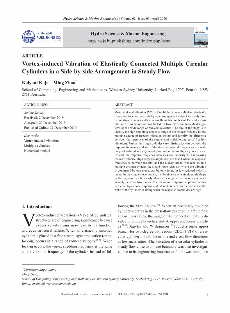
Hydro Science & Marine Engineering | Volume 02 | Issue 01 | April 2020
Distributed under creative commons license 4.0 DOI: https://doi.org/10.30564/hsme.v2i1.1504
Hydro Science & Marine Engineering
https://ojs.bilpublishing.com/index.php/hsme
ARTICLE
Vortex-induced Vibration of Elastically Connected Multiple Circular Cylinders in a Side-by-side Arrangement in Steady Flow
Kalyani Kaja Ming Zhao* School of Computing, Engineering and Mathematics, Western Sydney University, Locked Bag 1797, Penrith, NSW 2751, Australia
ARTICLE INFO ABSTRACT
Article historyReceived: 2 December 2019Accepted: 27 December 2019Published Online: 31 December 2019
Vortex-induced vibration (VIV) of multiple circular cylinders elastically connected together in a side-by-side arrangement subject to steady flow is investigated numerically at a low Reynolds number of 150 and a mass ratio of 2. Simulations are conducted for two-, five- and ten-cylinder sys-tems over a wide range of reduced velocities. The aim of the study is to identify the high-amplitude response range of the reduced velocity for the multiple degree of freedom vibration system and identify the difference between the responses of the single- and multiple-degree-of-freedom vibrations. Unlike the single cylinder case, distinct lock-in between the response frequency and any of the structural natural frequencies in a wide range of reduced velocity is not observed in the multiple-cylinder cases. Instead, the response frequency increases continuously with increasing reduced velocity. High response amplitudes are found when the response frequency is between the first and the highest modal frequencies. In a multiple-cylinder system, the single-mode response, where the vibration is dominated by one mode, can be only found in low reduced velocity range. In the single-mode branch, the dominance of a single mode shape in the response can be clearly identified except at the boundary reduced velocity between two modes. The maximum response amplitude occurs in the multiple-mode response and interaction between the vortices in the wake of the cylinders is strong when the response amplitudes are high.
Keywords:Vortex induced vibrationMultiple cylindersNumerical method
*Corresponding Author:Ming Zhao,School of Computing, Engineering and Mathematics, Western Sydney University, Locked Bag 1797, Penrith, NSW 2751, Australia;Email: [email protected]
1. Introduction
Vortex-induced vibrations (VIV) of cylindrical structures are of engineering significance because excessive vibrations may lead to malfunction
and even structural failure. When an elastically mounted cylinder is placed in a free stream, synchronization (or the lock-in) occurs in a range of reduced velocity [1-4]. When lock-in occurs, the vortex shedding frequency is the same as the vibration frequency of the cylinder, instead of fol-
lowing the Strouhal law [5]. When an elastically mounted cylinder vibrates in the cross-flow direction in a fluid flow at low mass ratios, the range of the reduced velocity is di-vided into three branches: initial, upper and lower branch-es [6,7]. Jauvtis and Williamson [8] found a super upper branch for two-degree-of-freedom (2DOF) VIV of a cir-cular cylinder in both the in-line and cross-flow directions at low mass ratios. The vibration of a circular cylinder in steady flow close to a plane boundary was also investigat-ed due to its engineering importance [9-12]. It was found that

2
Hydro Science & Marine Engineering | Volume 02 | Issue 01 | April 2020
Distributed under creative commons license 4.0
the plane boundary has significant effects on the vibration of the cylinder.
Numerical studies of VIV have been mostly conducted through two-dimensional simulations by solving either the 2D Navier-Stokes (NS) equations or the 2D Reynolds-Av-eraged Navier-Stokes equations (RANS). The numerical models based on the NS equations have provided satisfac-tory numerical solutions for VIV of a circular cylinder at low Reynolds numbers in the laminar flow regime [13-17]. The numerical models based on the RANS equations were found to provide satisfactory solutions of VIV of cylinders at higher Reynolds numbers in the subcritical flow regime
[18,19]. The research of flow past multiple cylinders has been
mainly focused on flow past two cylinders in different arrangements. The biased flow regime when the gap be-tween the cylinders is small was found in many studies of flow past two cylinders in a side-by-side arrangement [20,21]. Numerical studies of flow past two cylinders in side-by-side arrangement have also been conducted and the nu-merical results of the biased flow were found to agree well with the experimental data [22,23]. Recently, some studies of VIV of two or four cylinders have also been conducted both experimentally and numerically. Huera-Huarte and Gharib [24] conducted laboratory experiments of VIV of two side-by-side flexible cylinders at low mass ratios. It was found that the motions of the two cylinders are not synchronized if the centre-to-centre distance between the two cylinders is greater than 3.5 diameters. Wang et al. [25] focused their study of VIV of two side-by-side cylinders on the influence of the turbulence and found that the free-stream turbulence enhances the vortex-induced force and thus restores the large amplitude vibration associated with the lock-in resonance. Assi et al. [26] conducted experi-ments of VIV of an elastically mounted cylinder in the wake of a fixed identical cylinder and found that when the gap between the two cylinders is between 3 to 5.6 diam-eters, the vibration is in a galloping-like pattern. Kim et al. [27] studied VIV of two elastically mounted cylinders in a tandem arrangement and found five response regimes, depending on the distance between the two cylinders. Numerical studies of VIV of two cylinders have also been conducted recently [28-34], where the two cylinders were ei-ther in side-by-side, tandem or staggered arrangement.
Multiple cylinders are sometimes used in the fluid engineering, such as the multiple mooring cable in the offshore engineering or multiple heat exchanger tubes. If multiple-cylinders are elastically connected together, the system is a multiple-degree-of-freedom system with multiple natural frequencies. So far, little attention has been paid on VIV of elastically connected multiple cyl-
inder systems. Lock-in regime of the reduced velocity of elastically connected cylinders in fluid flow is expected to be wider than that of a single cylinder. Which natural fre-quencies the cylinders vibration locks onto is expected to depend on the reduced velocity.
In this study, VIV of elastically connected multiple circular cylinders in a side-by-side arrangement in steady flow is simulated numerically at a low Reynolds number of 150 and a low mass ratio of 2. The focus of the study is to investigate the response and lock-in behaviors of multi-degree-of-freedom (MDOF) systems. Since the flow is expected to be two-dimensional at Re=150, two-di-mensional Navier-Stokes equations are solved using the Petrov-Galerkin finite element method for simulating the flow and the equation of the motion of the cylinders is solved using the fourth-order Runge–Kutta method for predicting the response of the cylinders.
2. Numerical Method
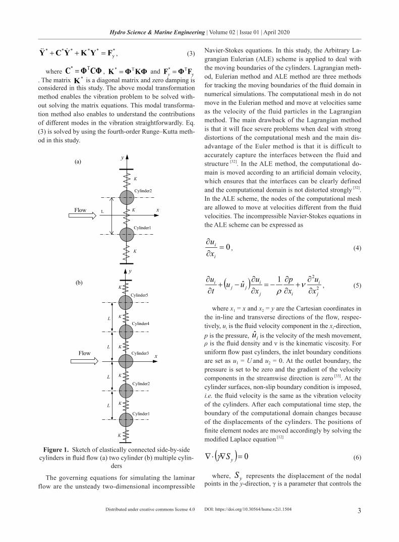
Flow induced vibration of elastically connected circular cylinders as shown in Figure 1 is simulated numerically. The cylinders are allowed to vibrate in the cross-flow di-rection only. It is assumed that diameter and mass of the cylinders are all identical. The initial distance between two adjacent cylinder centres is fixed at a constant of L=3D with D being the diameter of the cylinders. The dif-ferential equation of motion governing the vibration of the cylinders can be written as
yFKYYCYM =++ , (1)
where M, C and K are the symmetric mass, damping and stiffness matrices, respectively. The displacement vector Y contains the displacements of the cylinders in the cross-flow direction and is given by T
NYYY .,, 21 =Y, Fy is the corresponding vector of the forces on the cyl-inders, and N is the number of cylinders considered. The natural frequencies and the mode vectors of the system can be obtained by calculating the eigenvalues and the eigenvectors of the stiffness matrix. The solution of Eq. (1) can be expressed in the form
)()( tt *ΦYY = , (2)
where ,,, 21 NΦΦΦΦ = is the modal matrix of the system, kΦ stands for the kth-mode vector, and
)(t*Y is a column vector of generalized (modal) coor-dinates that are to be determined. The modal matrix Φ satisfies IMΦΦ =T where I is the unit matrix. The amplitude of )(t*Y is comprised of the response compo-nent of each mode. Substituting Eq. (2) into Eq. (1) yields
DOI: https://doi.org/10.30564/hsme.v2i1.1504
3
Hydro Science & Marine Engineering | Volume 02 | Issue 01 | April 2020
Distributed under creative commons license 4.0
*y
***** FYKYCY =++ , (3)
where CΦΦC T* = , KΦΦK T* = and yT* FΦF =y
. The matrix *K is a diagonal matrix and zero damping is considered in this study. The above modal transformation method enables the vibration problem to be solved with-out solving the matrix equations. This modal transforma-tion method also enables to understand the contributions of different modes in the vibration straightforwardly. Eq. (3) is solved by using the fourth-order Runge–Kutta meth-od in this study.
Flow
Cylinder1
Cylinder2
L
y
x
K
K
K
(a)
Flow
Cylinder2
Cylinder1
L
y
K
K
KCylinder3
Cylinder4
Cylinder5
K
K
K
xL
L
L
(b)
Figure 1. Sketch of elastically connected side-by-side cylinders in fluid flow (a) two cylinder (b) multiple cylin-
ders
The governing equations for simulating the laminar flow are the unsteady two-dimensional incompressible
Navier-Stokes equations. In this study, the Arbitrary La-grangian Eulerian (ALE) scheme is applied to deal with the moving boundaries of the cylinders. Lagrangian meth-od, Eulerian method and ALE method are three methods for tracking the moving boundaries of the fluid domain in numerical simulations. The computational mesh in do not move in the Eulerian method and move at velocities same as the velocity of the fluid particles in the Lagrangian method. The main drawback of the Lagrangian method is that it will face severe problems when deal with strong distortions of the computational mesh and the main dis-advantage of the Euler method is that it is difficult to accurately capture the interfaces between the fluid and structure [32]. In the ALE method, the computational do-main is moved according to an artificial domain velocity, which ensures that the interfaces can be clearly defined and the computational domain is not distorted strongly [32]. In the ALE scheme, the nodes of the computational mesh are allowed to move at velocities different from the fluid velocities. The incompressible Navier-Stokes equations in the ALE scheme can be expressed as
0=∂∂
i
i
xu
, (4)
( ) 2
21ˆj
i
ij
ijj
i
xu
xp
xuuu
tu
∂∂
+∂∂
−=∂∂
−+∂∂ ν
ρ, (5)
where x1 = x and x2 = y are the Cartesian coordinates in the in-line and transverse directions of the flow, respec-tively, ui is the fluid velocity component in the xi-direction, p is the pressure, iu is the velocity of the mesh movement, ρ is the fluid density and ν is the kinematic viscosity. For uniform flow past cylinders, the inlet boundary conditions are set as u1 = U and u2 = 0. At the outlet boundary, the pressure is set to be zero and the gradient of the velocity components in the streamwise direction is zero [33]. At the cylinder surfaces, non-slip boundary condition is imposed, i.e. the fluid velocity is the same as the vibration velocity of the cylinders. After each computational time step, the boundary of the computational domain changes because of the displacements of the cylinders. The positions of finite element nodes are moved accordingly by solving the modified Laplace equation [12]
( ) 0=∇⋅∇ ySγ (6)
where, yS represents the displacement of the nodal points in the y-direction, γ is a parameter that controls the
DOI: https://doi.org/10.30564/hsme.v2i1.1504
4
Hydro Science & Marine Engineering | Volume 02 | Issue 01 | April 2020
Distributed under creative commons license 4.0
mesh deformation. In order to avoid excessive deforma-tion of the near-wall elements, the parameter γ in a finite element is set to be A/1=γ , with A being the area of the element. The displacement of the mesh nodes is the same as the displacement of the cylinder on the cylinder surface and zero on other boundaries. By giving the displacements at all the boundaries, Eq. (6) is solved by the Galerkin FEM.
3. Numerical Results
The study is focused on the influence of the interference among multiple circular cylinders in a side-by-side ar-rangement on the response amplitudes and frequencies. Figure 1 shows a sketch of the arrangement of the cyl-inder system. The cylinders are numbered by cylinder 1 to cylinder N, respectively, where N is the total number of the cylinders. The springs that connect the cylinders have the same elastic coefficient of K. The cylinders are identical to each other and they have the same mass ratio of 2. The structural damping factor of the whole system is assumed to be 0 in all the simulations. The initial cen-ter-to-center distance between any two adjacent cylinders is 3D. In the review paper of flow past two cylinders in a side-by-side arrangement, Sumner [34] concluded that two parallel vortex streets occur in the wake of the two cylin-ders due to the weak wake interference if the gap between the two cylinders is greater than 1D. Because this study is focused on the effects of the multiple-degree-of-freedom on the response regime of the reduced velocity, the initial gap between two adjacent cylinders is chosen to be suffi-ciently large. The Reynolds number based on the cylinder diameter is fixed to be 150. Simulations are carried for two-cylinder, five-cylinder and ten-cylinder systems. The reduced velocity is defined based on the first mode natural frequency as )/( 1nr DfUV = , where fn1 is the first-mode structural natural frequency of the cylinders and U is the free-stream velocity. The responses of different systems are addressed separately in the following discussion.
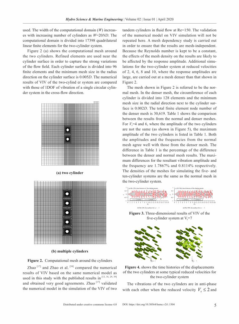
Zhao et al. [35] found that the wake flow in the wake of elastically mounted cylinder remains two-dimensional un-til the Reynolds number is 250 when the reduced velocity is 6, where the response amplitude reaches its maximum. To demonstrate that the flow is two dimensional for a Reynolds number of 150, some three-dimensional simula-tions of VIV of the five-cylinder system are performed for a reduced velocity of 7, which is in the middle of the lock-in range. The numerical method used for the three-dimen-sional simulation is the same as the one in Zhao et al. [35]. The computational mesh on the cross-sectional plane is the same as used in this study. The length of the cylinders is 6.4 diameters and totally 64 layers of elements are dis-
tributed along the axial direction of the cylinders. The to-tal element number is about 2.2 million. 16 CPUs are used for the parallel calculations. Three-dimensional numerical simulations are performed for a non-dimensional time of tfn1=19 and Figure 3 (a) and (c) shows the time histories of cylinders 1 and 5. The symmetric vibration develops to asymmetric vibration after tfn1=6 for both Reynolds num-bers.
The three-dimensional vortex shedding flow structure can be presented by the iso-surface of the second negative eigenvalue of the tensor 22 ΩΨ + , where Ψ and Ω are the symmetric and the anti-symmetric parts of the ve-locity-gradient tensor, respectively [36]. The nondimension-al second eigenvalue is defined as 2
22 )//( DUλλ ′= , where 2λ′ is dimensional eigenvalue. The iso-surfaces of 12 −=λ for Re=250 and 300 at tfn1=18.5 are shown in Figure 3 (b) and (d), respectively. It can be clearly seen that the flow is still two-dimensional when Re=250 and becomes three-dimensional when Re=300. It is in-teresting to see that the three-dimensional flow is mainly in the wake of the middle cylinder, where the wake flow is dominated by streamwise vortices. The three-dimen-sionality of the flow can be quantified by enstrophies
[37]. The primary enstrophy zε , the secondary xyε and
the total enstrophy ε are defined as Ω= ∫Ω d2zz ωε ,
Ω+= ∫Ω d)( 22yxxy ωωε , Ω++= ∫Ω d)( 222
zyx ωωωε, respectively, where Ω stands for the whole fluid vol-ume. The flow is three-dimensional if the secondary enstorphy is strong and two-dimensional if the second-ary enstrophy is zero. For the five-cylinder system, the nondimensional total enstrophies for Re=250 and 300 are
52 1098.2)//( ×=DUε and 51014.4 × , respectively, and the nondimensional secondary enstrophies for Re=250 and 300 are
12 1013.3)//( −×=DUxyε and 41060.1 × , respectively. The negligibly small secondary enstrophy for Re=250 demonstrates that the flow is still two-dimension-al. For Re=300, the secondary enstrophy still takes very small percentage in the total enstrophy, mainly because the three-dimensionality is strong only in the wake of the middle cylinder as shown in Figure 3 (d). If the flow is two-dimensional at Re=250, it is expected that the flow should be also two-dimensional when Re<250.
3.1 Two-cylinder System
Simulations are carried out for the reduced velocities ranging from 1 to 30 with an interval of 1 for the two-cyl-inder system. The ratio of the first- to second-mode nat-ural frequencies is fn2/fn1=1.732. A rectangular computa-tional domain with a length in the flow direction of 60D is
DOI: https://doi.org/10.30564/hsme.v2i1.1504
5
Hydro Science & Marine Engineering | Volume 02 | Issue 01 | April 2020
Distributed under creative commons license 4.0
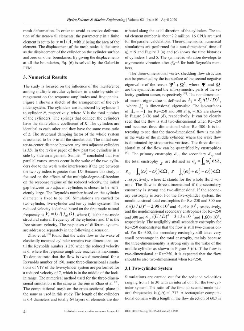
used. The width of the computational domain (W) increas-es with increasing number of cylinders as W=20ND. The computational domain is divided into 17398 quadrilateral linear finite elements for the two-cylinder system.
Figure 2 (a) shows the computational mesh around the two cylinders. Refined elements are used near the cylinder surface in order to capture the strong variations of the flow field. Each cylinder surface is divided into 96 finite elements and the minimum mesh size in the radius direction on the cylinder surface is 0.005D. The numerical results of VIV of the two-cylind er system are compared with those of 1DOF of vibration of a single circular cylin-der system in the cross-flow direction.
(a) two cylinder
(b) multiple cylinders
Figure 2. Computational mesh around the cylinders
Zhao [17] and Zhao et al. [38] compared the numerical results of VIV based on the same numerical model as used in this study with the published results in [13, 16, 29, 39] and obtained very good agreements. Zhao [17] validated the numerical model in the simulation of the VIV of two
tandem cylinders in fluid flow at Re=150. The validation of the numerical model on VIV simulation will not be repeated here. A mesh dependency study is carried out in order to ensure that the results are mesh-independent. Because the Reynolds number is kept to be a constant, the effects of the mesh density on the results are likely to be affected by the response amplitude. Additional simu-lations for the two-cylinder system at reduced velocities of 2, 4, 6, 8 and 10, where the response amplitudes are large, are carried out at a mesh denser than that shown in Figure 2.
The mesh shown in Figure 2 is referred to be the nor-mal mesh. In the denser mesh, the circumference of each cylinder is divided into 128 elements and the minimum mesh size in the radial direction next to the cylinder sur-face is 0.002D. The total finite element node number of the denser mesh is 30,619. Table 1 shows the comparison between the results from the normal and denser meshes. For Vr=4 and 6, where the amplitude of the two cylinders are not the same (as shown in Figure 5), the maximum amplitude of the two cylinders is listed in Table 1. Both the amplitudes and the frequencies from the normal mesh agree well with those from the denser mesh. The difference in Table 1 is the percentage of the difference between the denser and normal mesh results. The maxi-mum differences for the resultant vibration amplitude and the frequency are 1.7867% and 0.8114% respectively. The densities of the meshes for simulating the five- and ten-cylinder systems are the same as the normal mesh in the two-cylinder system.
-1
-0.5
0
0.5
1
0 1 2 3 4 5 6 7 8 9 10 11 12 13 14 15 16 17 18 19
Y
tfn1
Cylinder 1 Cylinder 5
(a) Re=250, time histories of the displacements
-1
-0.5
0
0.5
1
0 1 2 3 4 5 6 7 8 9 10 11 12 13 14 15 16 17 18 19 20
Y
tfn1
Cylinder 1 Cylinder 5
(c) R=300, time histories of the displacements
(b) Re=250, Isosurface of λ2 = –1 (d) Re=250, Isosurface of λ2 = –1 (b) Re=250, Iso-surface for λ2= – 1 (d) Re=300, Iso-surface for λ2= – 1
Figure 3. Three-dimensional results of VIV of the five-cylinder system at Vr=7
-1
-0.5
0
0.5
1
0 1 2 3 4 5 6 7 8 9 10 11 12 13 14 15 16 17 18 19
Y
tfn1
Cylinder 1 Cylinder 5
(a) Re=250, time histories of the displacements
-1
-0.5
0
0.5
1
0 1 2 3 4 5 6 7 8 9 10 11 12 13 14 15 16 17 18 19 20
Y
tfn1
Cylinder 1 Cylinder 5
(c) R=300, time histories of the displacements
(b) Re=250, Isosurface of λ2 = –1 (d) Re=250, Isosurface of λ2 = –1 (b) Re=250, Iso-surface for λ2= – 1 (d) Re=300, Iso-surface for λ2= – 1
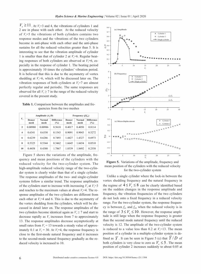
Figure 4. shows the time histories of the displacements of the two cylinders at some typical reduced velocities for
the two-cylinder system
The vibrations of the two cylinders are in anti-phase with each other when the reduced velocity 2r ≤V and
DOI: https://doi.org/10.30564/hsme.v2i1.1504
6
Hydro Science & Marine Engineering | Volume 02 | Issue 01 | April 2020
Distributed under creative commons license 4.0
11r ≥V . At Vr=3 and 4, the vibrations of cylinders 1 and 2 are in phase with each other. At the reduced velocity of Vr=5 the vibrations of both cylinders contains two response modes and the vibrations of the two cylinders become in anti-phase with each other and the anti-phase sustains for all the reduced velocities greater than 5. It is interesting to see that the vibration amplitude of cylinder 1 is smaller than that of cylinder 2 at Vr=6. Regular beat-ing responses of both cylinders are observed at Vr=6, es-pecially in the response of cylinder 1. The beating period is approximately 10 times the cylinders’ vibration period. It is believed that this is due to the asymmetry of vortex shedding at Vr=6, which will be discussed later on. The vibration responses of both cylinders at Vr=7 are almost perfectly regular and periodic. The same responses are observed for all Vr ≥ 7 in the range of the reduced velocity covered in the present study.
Table 1. Comparison between the amplitudes and fre-quencies from the two meshes
Vr
Amplitude (Ay/D) Frequency (f/fn1)
Denser mesh
Normal mesh
Difference (%)
Denser mesh
Normal mesh
Difference (%)
2 0.00980 0.00986 0.5618 0.4017 0.4050 0.8114
4 0.6341 0.6350 0.1543 0.9091 0.9043 0.5272
6 0.6239 0.6286 0.7493 1.4427 1.4327 0.6973
8 0.5325 0.5344 0.3462 1.6645 1.6654 0.0510
10 0.4458 0.4380 1.7867 1.8539 1.8492 0.2558
Figure 5 shows the variations of the amplitude, fre-quency and mean positions of the cylinders with the reduced velocity for the two-cylinder system. The high-amplitude reduced velocity range of the two-cylin-der system is clearly wider than that of a single cylinder. The response amplitudes of the two- and single-cylinder systems follow a similar trend. The response amplitudes of the cylinders start to increase with increasing Vr at Vr=3 and reaches to the maximum values at about Vr=4. The re-sponse amplitudes of the two cylinders are different from each other at Vr=4 and 6. This is due to the asymmetry of the vortex shedding from the cylinders, which will be dis-cussed in detail later on. The response amplitudes of the two cylinders become identical again as Vr ≥ 7 and start to decrease rapidly as Vr increases from 7 to approximately 13. The response amplitudes decrease asymptotically at small rates from Vr = 13 towards a steady value of approx-imately 0.1 at Vr = 30. At Vr=4, the response frequency is close to the first-mode natural frequency and it increases to the second-mode natural frequency gradually as the re-duced velocity is increased to 10.
0
0.1
0.2
0.3
0.4
0.5
0.6
0.7
0.8
0 5 10 15 20 25 30
A y/D
Vr
Cylinder 1
Cylinder 2
Single cylinder
(a) Amplitude
0
1
2
3
4
5
6
0 5 10 15 20 25 30
f/fn1
Vr
Cylinder 1Cylinder 2Single cylinder
fn2/fn1
fn1/fn1
(b) Frequency
-0.3
-0.2
-0.1
0
0.1
0.2
0.3
0 5 10 15 20 25 30
Y/D
Vr
Cylinder 1
Cylinder 2(c) Mean displacement
Figure 5. Variations of the amplitude, frequency and mean position of the cylinders with the reduced velocity
for the two-cylinder system
Unlike a single cylinder where the lock-in between the vortex shedding frequency and the natural frequency in the regime of 84 r ≤≤V can be clearly identified based on the sudden changes in the response amplitude and frequency, the vibration frequencies of the two cylinders do not lock onto a fixed frequency in a reduced velocity range. For the two-cylinder system, the response frequen-cy is between fn1 and fnN when the reduced velocity is in the range of 103 r ≤≤V . However, the response ampli-tude is still large when the response frequency is greater than the second mode natural frequency until the reduced velocity is 12. The amplitude of the two-cylinder system is reduced to a value less than 0.2 at Vr=13. The mean position of a cylinder in a multiple-cylinder system is de-fined as Y . It can be seen in Figure 5 (c) that DY / of both cylinders is very close to zero as 5r ≤V . The mean position of cylinder 2 increases suddenly to about 0.05 at
DOI: https://doi.org/10.30564/hsme.v2i1.1504
7
Hydro Science & Marine Engineering | Volume 02 | Issue 01 | April 2020
Distributed under creative commons license 4.0
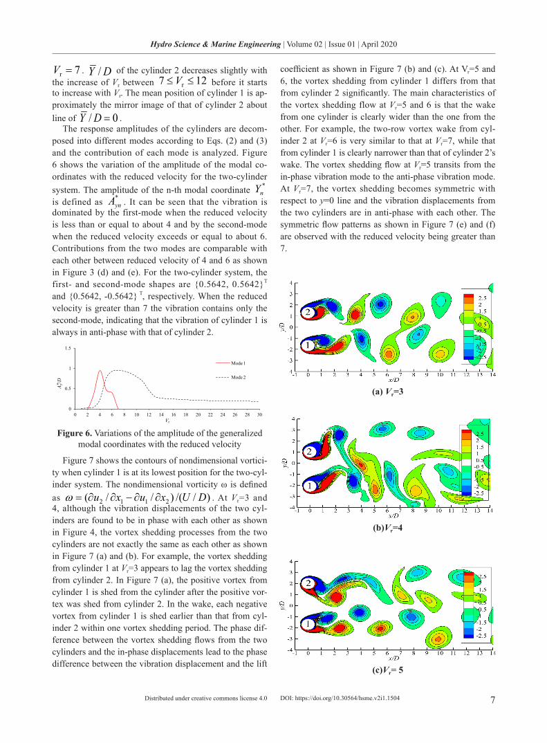
7r =V . DY / of the cylinder 2 decreases slightly with the increase of Vr between 127 r ≤≤V before it starts to increase with Vr. The mean position of cylinder 1 is ap-proximately the mirror image of that of cylinder 2 about line of 0/ =DY .
The response amplitudes of the cylinders are decom-posed into different modes according to Eqs. (2) and (3) and the contribution of each mode is analyzed. Figure 6 shows the variation of the amplitude of the modal co-ordinates with the reduced velocity for the two-cylinder system. The amplitude of the n-th modal coordinate *
nY is defined as *
ynA . It can be seen that the vibration is dominated by the first-mode when the reduced velocity is less than or equal to about 4 and by the second-mode when the reduced velocity exceeds or equal to about 6. Contributions from the two modes are comparable with each other between reduced velocity of 4 and 6 as shown in Figure 3 (d) and (e). For the two-cylinder system, the first- and second-mode shapes are 0.5642, 0.5642T and 0.5642, -0.5642 T, respectively. When the reduced velocity is greater than 7 the vibration contains only the second-mode, indicating that the vibration of cylinder 1 is always in anti-phase with that of cylinder 2.
0
0.5
1
1.5
0 2 4 6 8 10 12 14 16 18 20 22 24 26 28 30
A y/D
Vr
Mode 1
Mode 2*
Figure 6. Variations of the amplitude of the generalized modal coordinates with the reduced velocity
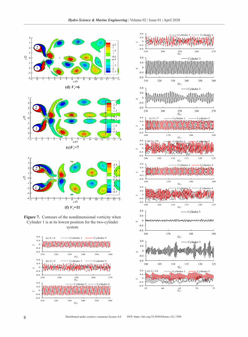
Figure 7 shows the contours of nondimensional vortici-ty when cylinder 1 is at its lowest position for the two-cyl-inder system. The nondimensional vorticity ω is defined as )//()//( 2112 DUxuxu ∂∂−∂∂=ω . At Vr=3 and 4, although the vibration displacements of the two cyl-inders are found to be in phase with each other as shown in Figure 4, the vortex shedding processes from the two cylinders are not exactly the same as each other as shown in Figure 7 (a) and (b). For example, the vortex shedding from cylinder 1 at Vr=3 appears to lag the vortex shedding from cylinder 2. In Figure 7 (a), the positive vortex from cylinder 1 is shed from the cylinder after the positive vor-tex was shed from cylinder 2. In the wake, each negative vortex from cylinder 1 is shed earlier than that from cyl-inder 2 within one vortex shedding period. The phase dif-ference between the vortex shedding flows from the two cylinders and the in-phase displacements lead to the phase difference between the vibration displacement and the lift
coefficient as shown in Figure 7 (b) and (c). At Vr=5 and 6, the vortex shedding from cylinder 1 differs from that from cylinder 2 significantly. The main characteristics of the vortex shedding flow at Vr=5 and 6 is that the wake from one cylinder is clearly wider than the one from the other. For example, the two-row vortex wake from cyl-inder 2 at Vr=6 is very similar to that at Vr=7, while that from cylinder 1 is clearly narrower than that of cylinder 2’s wake. The vortex shedding flow at Vr=5 transits from the in-phase vibration mode to the anti-phase vibration mode. At Vr=7, the vortex shedding becomes symmetric with respect to y=0 line and the vibration displacements from the two cylinders are in anti-phase with each other. The symmetric flow patterns as shown in Figure 7 (e) and (f) are observed with the reduced velocity being greater than 7.
(a) Vr=3
(b)Vr=4
(c)Vr= 5
DOI: https://doi.org/10.30564/hsme.v2i1.1504
8
Hydro Science & Marine Engineering | Volume 02 | Issue 01 | April 2020
Distributed under creative commons license 4.0
(d) Vr=6
(e)Vr=7
(f) Vr=11
Figure 7. Contours of the nondimensional vorticity when Cylinder 1 is at its lowest position for the two-cylinder
system
-0.8
-0.4
0
0.4
0.8
310 320 330 340 350 360
Y
tfn1
Cylinder 1 Cylinder 5(a) Vr=4
-0.8
-0.4
0
0.4
0.8
230 240 250 260 270
Y
tfn1
Cylinder 1 Cylinder 5(b) Vr=5
-0.8
-0.4
0
0.4
0.8
310 320 330 340 350 360
Y
tfn1
Cylinder 2 Cylinder 4
-0.8
-0.4
0
0.4
0.8
230 240 250 260 270
Y
tfn1
Cylinder 2 Cylinder 4
-0.8
-0.4
0
0.4
0.8
310 320 330 340 350 360
Y
tfn1
Cylinder 3
-0.8
-0.4
0
0.4
0.8
230 240 250 260 270
Y
tfn1
Cylinder 3
-0.8
-0.4
0
0.4
0.8
160 170 180 190Y
tfn1
Cylinder 1 Cylinder 5(c) Vr=7
-0.8
-0.4
0
0.4
0.8
100 105 110 115 120 125
Y
tfn1
Cylinder 1 Cylinder 5(d) Vr=10
-0.8
-0.4
0
0.4
0.8
160 170 180 190
Y
tfn1
Cylinder 2 Cylinder 4
-0.8
-0.4
0
0.4
0.8
100 105 110 115 120 125
Y
tfn1
Cylinder 2 Cylinder 4
-0.8
-0.4
0
0.4
0.8
160 170 180 190
Y
tfn1
Cylinder 3
-0.8
-0.4
0
0.4
0.8
100 105 110 115 120 125
Y
tfn1
Cylinder 3
-0.8
-0.4
0
0.4
0.8
55 60 65 70 75
Y
tfn1
Cylinder 1 Cylinder 5(e) Vr=16
DOI: https://doi.org/10.30564/hsme.v2i1.1504
9
Hydro Science & Marine Engineering | Volume 02 | Issue 01 | April 2020
Distributed under creative commons license 4.0
-0.8
-0.4
0
0.4
0.8
30 35 40 45 50
Y
tfn1
Cylinder 1 Cylinder 5(f) Vr=25
-0.8
-0.4
0
0.4
0.8
55 60 65 70 75
Y
tfn1
Cylinder 2 Cylinder 4
-0.8
-0.4
0
0.4
0.8
30 35 40 45 50
Y
tfn1
Cylinder 2 Cylinder 4
-0.8
-0.4
0
0.4
0.8
55 60 65 70 75
Y
tfn1
Cylinder 3
-0.8
-0.4
0
0.4
0.8
30 35 40 45 50
Y
tfn1
Cylinder 3
Figure 8. Time histories of the vibration displacement for the five-cylinder system
3.2 Five-cylinder System
The VIV of five elastically connected cylinders in a side-by-side arrangement is simulated in the reduced velocities range from 1 to 40 with an interval of 1. The computational mesh around the cylinders is shown in Figure 2 (b). Figure 8 shows the time histories of the responses of the five cyl-inders at some representative reduced velocities. The time histories of the responses of cylinders 1 and 5 are plotted together because they are geometrically symmetric about the central cylinder 3. The time histories of the responses of cylinders 2 and 4 are plotted together for the same rea-son. Similar to the two-cylinder system, the displacements of cylinders 1 and 2 are in phase with those of cylinders 5 and 3 respectively at Vr=3 and 4. The vibrations of all five cylinders become irregular at Vr=5. The vibration appears irregular due to the combination of more than one response modes in the response. The time histories of the responses of cylinders 1 and 2 are still generally in phase with those of cylinders 5 and 4 correspondingly at Vr=5. The vibration appears more irregular than that of the two-cylinder system because more frequency components are in the response. The frequencies of the irregular vibrations are analyzed us-ing the Fast Fourier Transform (FFT).
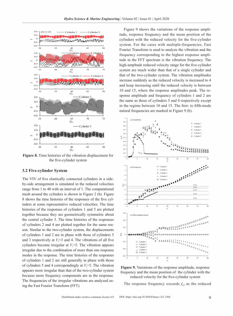
Figure 9 shows the variations of the response ampli-tude, response frequency and the mean position of the cylinders with the reduced velocity for the five-cylinder system. For the cases with multiple-frequencies, Fast Fourier Transform is used to analyze the vibration and the frequency corresponding to the highest response ampli-tude in the FFT spectrum is the vibration frequency. The high-ampltude reduced velocity range for the five-cylinder system are much wider than that of a single cylinder and that of the two-cylinder system. The vibration amplitudes increase suddenly as the reduced velocity is increased to 4 and keep increasing until the reduced velocity is between 10 and 15, where the response amplitudes peak. The re-sponse amplitude and frequency of cylinders 1 and 2 are the same as those of cylinders 5 and 4 respectively except in the regime between 10 and 15. The first- to fifth-mode natural frequencies are marked in Figure 9 (b).
0
0.1
0.2
0.3
0.4
0.5
0.6
0.7
0.8
0.9
1
0 5 10 15 20 25 30 35 40
A y/D
Vr
Cylinder 1
Cylinder 2
Cylinder 3
Cylinder 4
Cylinder 5
(a) Ampliutde
0
1
2
3
4
5
6
7
8
0 5 10 15 20 25 30 35 40
f/fn1
Vr
Cylinder 1
Cylinder 2
Cylinder 3
Cylinder 4
Cylinder 5
fn5/fn1
fn4/fn1
fn3/fn1
fn2/fn1
fn1/fn1
(b) Frequency
-0.6
-0.4
-0.2
0
0.2
0.4
0.6
0 5 10 15 20 25 30 35 40
Y/D
Vr
Cylinder 1Cylinder 2Cylinder 3Cylinder 4Cylinder 5
(c) Mean displacement
Figure 9. Variations of the response amplitude, response frequency and the mean position of the cylinder with the
reduced velocity for the five-cylinder system
The response frequency exceeds fn5 as the reduced
DOI: https://doi.org/10.30564/hsme.v2i1.1504

10
Hydro Science & Marine Engineering | Volume 02 | Issue 01 | April 2020
Distributed under creative commons license 4.0
velocity is greater than 18. After the response frequency exceeds fn5, the response amplitudes of all five cylinders decrease gradually with increasing Vr. In the reduced ve-locity range of 183 r ≤≤V the response frequency is between the first- and fifth-mode frequencies. The upper boundary reduced velocity based on the highest natu-ral frequency is Vr5=4.80. It is interesting to see that the response frequencies of the two side cylinders 1 and 5 are the same but they are slightly different from those of other middle cylinders 4 and 2. This is likely because of the difference between the approaching flow conditions to cylinders 1 and 2 (or cylinders 5 and 4), for example, caused by flow blockage and cylinder interference. The mean positions of the five cylinders remain to be around zero for 7r ≤V where response frequencies are clos-er to the first-mode natural frequency than other mode natural frequencies. The mean positions of cylinders 4 and 5 increases gradually to about 0.1 from Vr = 7 to Vr = 15 where the response frequencies of cylinders 4 and 5 increase from close to second-mode natural frequency to the fourth-mode natural frequency. There appear to be sudden increases of the mean positions of cylinders 4 and 5 from Vr = 15 to Vr = 16 which correspond to the changes of response frequencies from approximately 4th-mode nat-ural frequency to 5th-mode natural frequency. The mean positions of cylinders 4 and 5 remain at steady values in the range of 2516 r ≤≤V where response frequencies are greater than the 5th-mode natural frequency and the response amplitude reduces with increasing reduced ve-locity. The mean positions of cylinders 4 and 5 start to increase with Vr as Vr>25. The mean positions of cylinder 1 and cylinder 2 are approximately the mirror images of the mean positions of cylinders 5 and 4 about the line of
0/ =DY .Figure 10 shows the variations of the amplitude of
the modal coordinates with the reduced velocity for the five-cylinder system. Mode 1 dominates the vibration response when the reduced velocity is less than 4 and mode 2 dominate the vibration when Vr=6 and 7. The vi-bration response is evenly dominated by Modes 1 and 2 at
5r =V , which is the boundary reduced velocity between modes 1 and 2. As the reduced velocity exceeds 7, the contributions from modes 3 to 5 become significant while the modes 1 and 2 components of vibration response are still obvious. In the range of 158 r ≤≤V , where the response energy is almost evenly distributed among the five modes, the amplitudes are obviously higher than those in other reduced velocities. The variation of the re-sponse frequency with the reduced velocity in the range of
158 r ≤≤V is also weak. The response is dominated by mode 5 as the reduced velocity exceeds 16. The response
frequency is close to the mode 5 frequency at Vr=16 and exceeds mode 5 frequency at Vr=17 as shown in Figure 9 (b). For the five-cylinder system the range 73 r ≤≤V is referred to be the single-mode branch because the single mode can be clearly identified except at the boundary be-tween two modes. The range of 188 r ≤≤V is referred to be the multiple-mode branch. The reduced velocities of 16, 17 and 18 are in the multiple-mode branch because the contributions from modes 1 to 4 are obvious, but are less significant than that from mode 5.
0
0.5
1
1.5
0 5 10 15 20 25 30 35 40
A y/D
Vr
Mode 1Mode 2Mode 3Mode 4Mode 5*
Figure 10. Variations of the amplitude of the modal co-ordinates with the reduced velocity for the five-cylinder
system
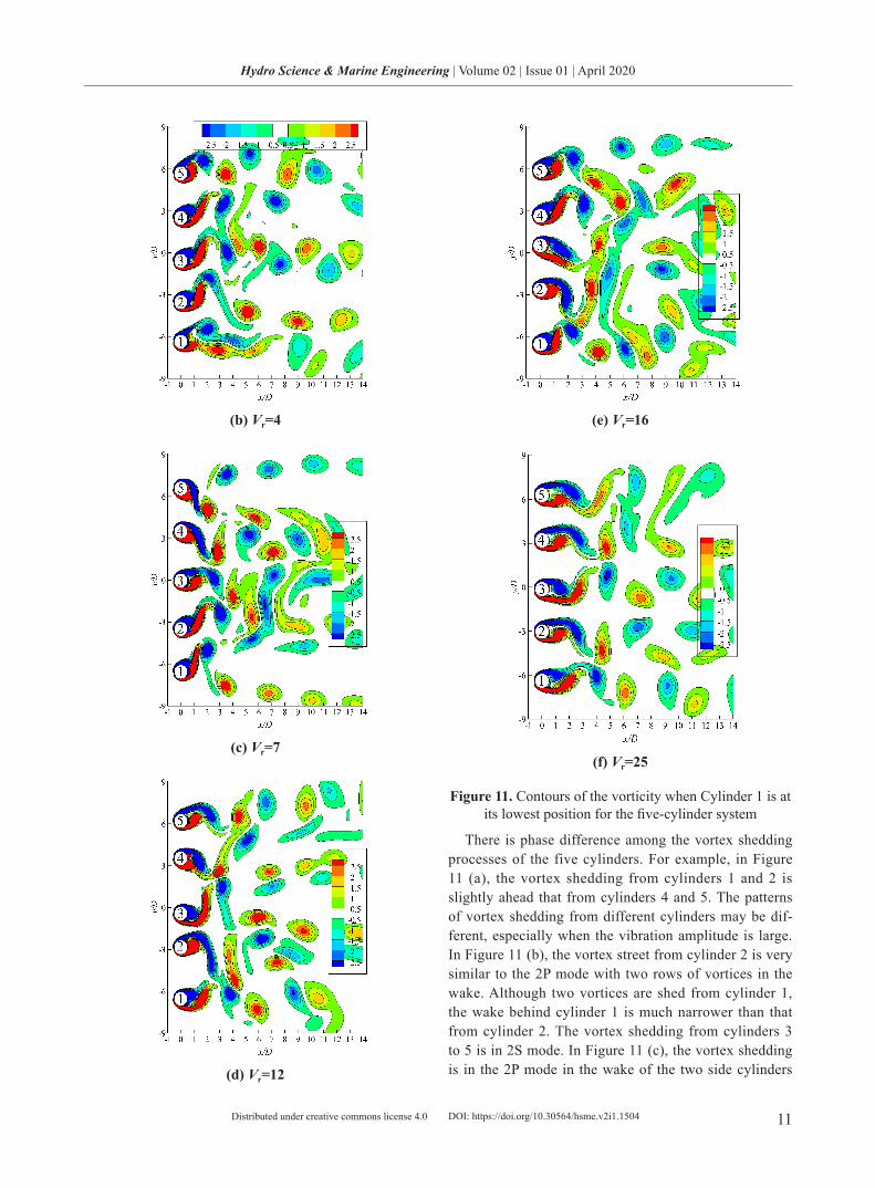
Figure 11 shows vorticity contours of the near wakes of the cylinders when cylinder 1 is at its lowest position in the cross-flow direction. It can be seen that the inter-action among the vortices are strong at Vr=4 to 16, where the response amplitudes of the cylinders are large. The interactions among the vortices shed from adjacent cylin-ders take place right behind the cylinders in Figure 11 (b) to (e). The strong interactions among the vortices lead to very irregular vibration displacement. Merging of the two or three vortices of the same signs is very common in the wake. It appears that the vortices that are shed from the bottom of cylinder 1 and the top of cylinder 5 are less af-fected by the interaction especially in Figure 11 (c).
(a) Vr=2
DOI: https://doi.org/10.30564/hsme.v2i1.1504
11
Hydro Science & Marine Engineering | Volume 02 | Issue 01 | April 2020
Distributed under creative commons license 4.0
(b) Vr=4
(c) Vr=7
(d) Vr=12
(e) Vr=16
(f) Vr=25
Figure 11. Contours of the vorticity when Cylinder 1 is at its lowest position for the five-cylinder system
There is phase difference among the vortex shedding processes of the five cylinders. For example, in Figure 11 (a), the vortex shedding from cylinders 1 and 2 is slightly ahead that from cylinders 4 and 5. The patterns of vortex shedding from different cylinders may be dif-ferent, especially when the vibration amplitude is large. In Figure 11 (b), the vortex street from cylinder 2 is very similar to the 2P mode with two rows of vortices in the wake. Although two vortices are shed from cylinder 1, the wake behind cylinder 1 is much narrower than that from cylinder 2. The vortex shedding from cylinders 3 to 5 is in 2S mode. In Figure 11 (c), the vortex shedding is in the 2P mode in the wake of the two side cylinders
DOI: https://doi.org/10.30564/hsme.v2i1.1504
12
Hydro Science & Marine Engineering | Volume 02 | Issue 01 | April 2020
Distributed under creative commons license 4.0
1 and 5. The bottom row of the vortices from cylinder 1 and the top row of the vortices from cylinder 5 do not participate in the interactions with other vortices, while the vortices in the wake of the three middle cylinders in-teract actively.
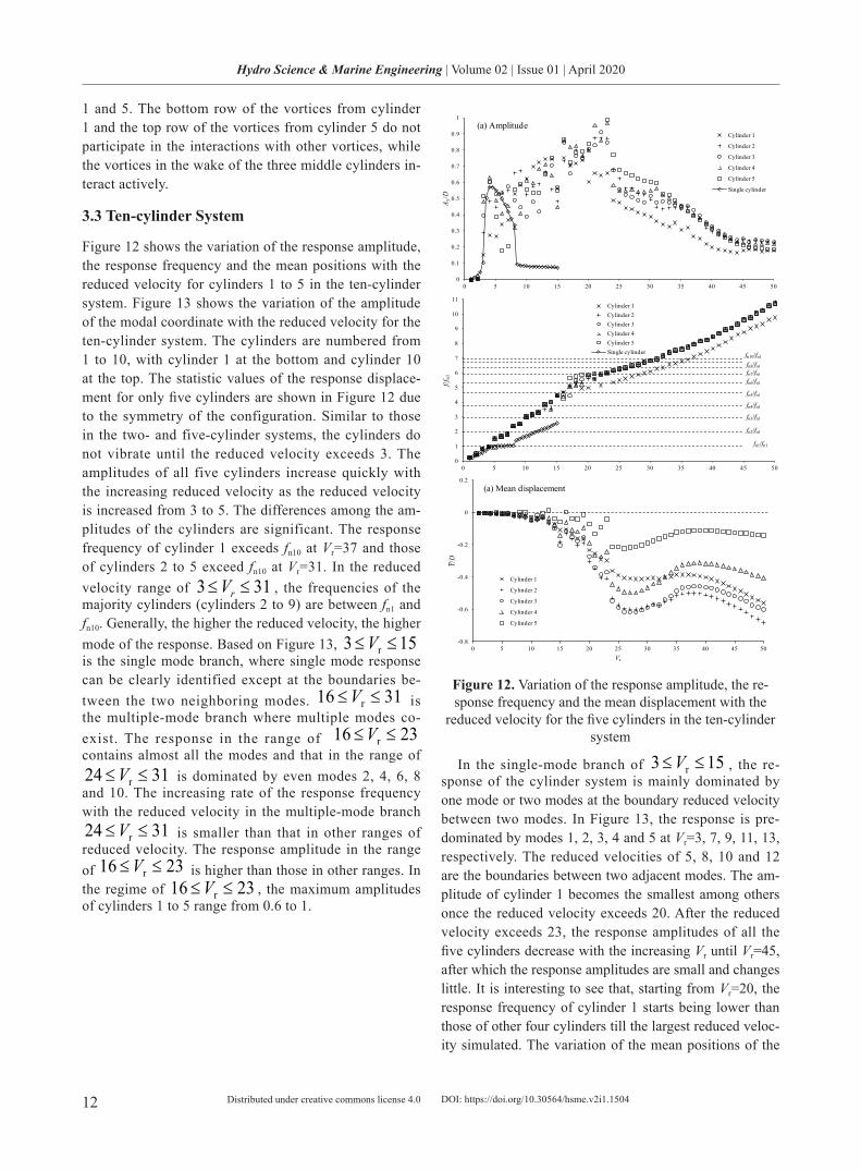
3.3 Ten-cylinder System
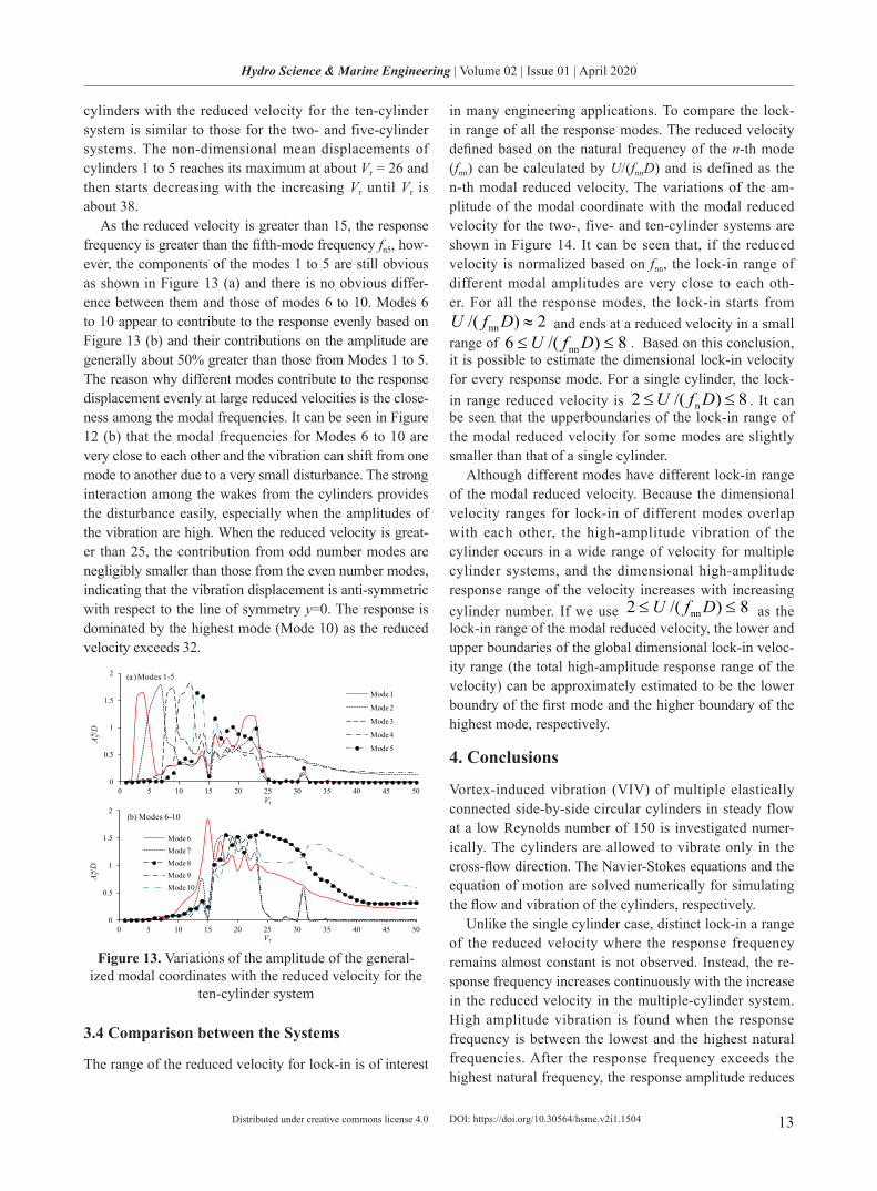
Figure 12 shows the variation of the response amplitude, the response frequency and the mean positions with the reduced velocity for cylinders 1 to 5 in the ten-cylinder system. Figure 13 shows the variation of the amplitude of the modal coordinate with the reduced velocity for the ten-cylinder system. The cylinders are numbered from 1 to 10, with cylinder 1 at the bottom and cylinder 10 at the top. The statistic values of the response displace-ment for only five cylinders are shown in Figure 12 due to the symmetry of the configuration. Similar to those in the two- and five-cylinder systems, the cylinders do not vibrate until the reduced velocity exceeds 3. The amplitudes of all five cylinders increase quickly with the increasing reduced velocity as the reduced velocity is increased from 3 to 5. The differences among the am-plitudes of the cylinders are significant. The response frequency of cylinder 1 exceeds fn10 at Vr=37 and those of cylinders 2 to 5 exceed fn10 at Vr=31. In the reduced velocity range of 313 ≤≤ rV , the frequencies of the majority cylinders (cylinders 2 to 9) are between fn1 and fn10. Generally, the higher the reduced velocity, the higher mode of the response. Based on Figure 13, 153 r ≤≤V is the single mode branch, where single mode response can be clearly identified except at the boundaries be-tween the two neighboring modes. 3116 r ≤≤V is the multiple-mode branch where multiple modes co-exist. The response in the range of 2316 r ≤≤V contains almost all the modes and that in the range of
3124 r ≤≤V is dominated by even modes 2, 4, 6, 8 and 10. The increasing rate of the response frequency with the reduced velocity in the multiple-mode branch
3124 r ≤≤V is smaller than that in other ranges of reduced velocity. The response amplitude in the range of 2316 r ≤≤V is higher than those in other ranges. In the regime of 2316 r ≤≤V , the maximum amplitudes of cylinders 1 to 5 range from 0.6 to 1.
0
0.1
0.2
0.3
0.4
0.5
0.6
0.7
0.8
0.9
1
0 5 10 15 20 25 30 35 40 45 50
A y/D
Vr
Cylinder 1
Cylinder 2
Cylinder 3
Cylinder 4
Cylinder 5
Single cylinder
(a) Amplitude
0
1
2
3
4
5
6
7
8
9
10
11
0 5 10 15 20 25 30 35 40 45 50
f/fn1
Vr
Cylinder 1Cylinder 2Cylinder 3Cylinder 4Cylinder 5Single cylinder
fn5/fn1
fn4/fn1
fn3/fn1
fn2/fn1
fn1/fn1
fn10/fn1
fn8/fn1fn7/fn1
fn6/fn1
-0.8
-0.6
-0.4
-0.2
0
0.2
0 5 10 15 20 25 30 35 40 45 50
Y/D
Vr
Cylinder 1
Cylinder 2
Cylinder 3
Cylinder 4
Cylinder 5
(a) Mean displacement
Figure 12. Variation of the response amplitude, the re-sponse frequency and the mean displacement with the
reduced velocity for the five cylinders in the ten-cylinder system
In the single-mode branch of 153 r ≤≤V , the re-sponse of the cylinder system is mainly dominated by one mode or two modes at the boundary reduced velocity between two modes. In Figure 13, the response is pre-dominated by modes 1, 2, 3, 4 and 5 at Vr=3, 7, 9, 11, 13, respectively. The reduced velocities of 5, 8, 10 and 12 are the boundaries between two adjacent modes. The am-plitude of cylinder 1 becomes the smallest among others once the reduced velocity exceeds 20. After the reduced velocity exceeds 23, the response amplitudes of all the five cylinders decrease with the increasing Vr until Vr=45, after which the response amplitudes are small and changes little. It is interesting to see that, starting from Vr=20, the response frequency of cylinder 1 starts being lower than those of other four cylinders till the largest reduced veloc-ity simulated. The variation of the mean positions of the
DOI: https://doi.org/10.30564/hsme.v2i1.1504
13
Hydro Science & Marine Engineering | Volume 02 | Issue 01 | April 2020
Distributed under creative commons license 4.0
cylinders with the reduced velocity for the ten-cylinder system is similar to those for the two- and five-cylinder systems. The non-dimensional mean displacements of cylinders 1 to 5 reaches its maximum at about Vr = 26 and then starts decreasing with the increasing Vr until Vr is about 38.
As the reduced velocity is greater than 15, the response frequency is greater than the fifth-mode frequency fn5, how-ever, the components of the modes 1 to 5 are still obvious as shown in Figure 13 (a) and there is no obvious differ-ence between them and those of modes 6 to 10. Modes 6 to 10 appear to contribute to the response evenly based on Figure 13 (b) and their contributions on the amplitude are generally about 50% greater than those from Modes 1 to 5. The reason why different modes contribute to the response displacement evenly at large reduced velocities is the close-ness among the modal frequencies. It can be seen in Figure 12 (b) that the modal frequencies for Modes 6 to 10 are very close to each other and the vibration can shift from one mode to another due to a very small disturbance. The strong interaction among the wakes from the cylinders provides the disturbance easily, especially when the amplitudes of the vibration are high. When the reduced velocity is great-er than 25, the contribution from odd number modes are negligibly smaller than those from the even number modes, indicating that the vibration displacement is anti-symmetric with respect to the line of symmetry y=0. The response is dominated by the highest mode (Mode 10) as the reduced velocity exceeds 32.
0
0.5
1
1.5
2
0 5 10 15 20 25 30 35 40 45 50
A y/D
Vr
Mode 1
Mode 2
Mode 3
Mode 4
Mode 5
(a) Modes 1-5
*
0
0.5
1
1.5
2
0 5 10 15 20 25 30 35 40 45 50
A y/D
Vr
Mode 6Mode 7Mode 8Mode 9Mode 10
(b) Modes 6-10
*
Figure 13. Variations of the amplitude of the general-ized modal coordinates with the reduced velocity for the
ten-cylinder system
3.4 Comparison between the Systems
The range of the reduced velocity for lock-in is of interest
in many engineering applications. To compare the lock-in range of all the response modes. The reduced velocity defined based on the natural frequency of the n-th mode (fnn) can be calculated by U/(fnnD) and is defined as the n-th modal reduced velocity. The variations of the am-plitude of the modal coordinate with the modal reduced velocity for the two-, five- and ten-cylinder systems are shown in Figure 14. It can be seen that, if the reduced velocity is normalized based on fnn, the lock-in range of different modal amplitudes are very close to each oth-er. For all the response modes, the lock-in starts from
2)/( nn ≈DfU and ends at a reduced velocity in a small range of 8)/(6 nn ≤≤ DfU . Based on this conclusion, it is possible to estimate the dimensional lock-in velocity for every response mode. For a single cylinder, the lock-in range reduced velocity is 8)/(2 n ≤≤ DfU . It can be seen that the upperboundaries of the lock-in range of the modal reduced velocity for some modes are slightly smaller than that of a single cylinder.
Although different modes have different lock-in range of the modal reduced velocity. Because the dimensional velocity ranges for lock-in of different modes overlap with each other, the high-amplitude vibration of the cylinder occurs in a wide range of velocity for multiple cylinder systems, and the dimensional high-amplitude response range of the velocity increases with increasing cylinder number. If we use 8)/(2 nn ≤≤ DfU as the lock-in range of the modal reduced velocity, the lower and upper boundaries of the global dimensional lock-in veloc-ity range (the total high-amplitude response range of the velocity) can be approximately estimated to be the lower boundry of the first mode and the higher boundary of the highest mode, respectively.
4. Conclusions
Vortex-induced vibration (VIV) of multiple elastically connected side-by-side circular cylinders in steady flow at a low Reynolds number of 150 is investigated numer-ically. The cylinders are allowed to vibrate only in the cross-flow direction. The Navier-Stokes equations and the equation of motion are solved numerically for simulating the flow and vibration of the cylinders, respectively.
Unlike the single cylinder case, distinct lock-in a range of the reduced velocity where the response frequency remains almost constant is not observed. Instead, the re-sponse frequency increases continuously with the increase in the reduced velocity in the multiple-cylinder system. High amplitude vibration is found when the response frequency is between the lowest and the highest natural frequencies. After the response frequency exceeds the highest natural frequency, the response amplitude reduces
DOI: https://doi.org/10.30564/hsme.v2i1.1504
14
Hydro Science & Marine Engineering | Volume 02 | Issue 01 | April 2020
Distributed under creative commons license 4.0
with increasing reduced velocity, but remains high for a small range of reduced velocities.
The modal coordinates of the response are analyzed in order to understand the contribution of each mode in the response. It is found that the response is general-ly in high mode at high reduced velocities for the five- and ten-cylinder systems. The dominance of a single mode in the vibration can only be found for low modal frequencies. The single-mode response can be found in the range of 73 r ≤≤V for the five cylinder system and 153 r ≤≤V for the ten cylinder system. At higher reduced velocities the contributions of all the response modal shapes are found to be comparable with each other. This is because the closeness among the high modal fre-quencies makes the vibration switching from one mode to another easily under even very small disturbances, while the strong interaction among the wake flows provides the source of disturbances. Based on the results for the five- and ten-cylinder systems, it is found that the single mode for about half of the natural frequencies can be identified, while the lowest frequency has the clearest single mode.
In the two-cylinder system, the response amplitudes of the two cylinders are the same except in the range of
64 r ≤≤V , where the response amplitudes reach to their maximum values. For the five- and ten-cylinder systems, the response amplitudes of the cylinders are not the same and the difference among the amplitudes of the cylinders is high when the response amplitude is high. Strong inter-actions among the vortex shedding flows from different cylinders occur at high response amplitudes, resulting in a chaotic vortex shedding pattern. There are large phase differences among the vortex shedding processes from different cylinders in a multiple-cylinder system.
References
[1] Williamson, C. H. K. and Roshko, A.. Vortex forma-tion in the wake of an oscillating cylinder. Journal of Fluids and Structures, 1988, 2: 355-381.
[2] Sarpkaya, T.. A critical review of the intrinsic nature of vortex-induced vibrations. Journal of Fluids and Structures, 2004, 19: 389–447.
[3] Govardhan, R., Williamson, C. H. K.. Modes of vor-tex formation and frequency response for a freely-vi-brating cylinder. Journal of Fluid Mechanics, 2000, 420: 85-130.
[4] Williamson, C.H.K., Govardhan, R.. Vortex-induced vibrations. Annual Review of Fluid Mechanics, 2004, 36: 413–455.
[5] Sarpakaya, T., Isaacson, M.. Mechanics of wave forces on offshore structures (first ed). Van Nostrand Reinhold, 1981.
[6] Khalak, A., Williamson, C.H.K.. Dynamics of a hy-droelastic cylinder with very low mass and damping. Journal of Fluids and Structures, 1996, 10: 455–472.
[7] Khalak, A., Williamson, C. H. K.. Motions, forces and mode transitions in vortex-induced vibrations at low mass-damping, Journal of fluids and Structures, 1999, 13: 813-851.
[8] Jauvtis, N., Williamson, C. H. K.. The effect of two degrees of freedom on vortex-induced vibration at low mass and damping, Journal of Fluid Mechanics, 2004, 509: 23-62.
[9] Fredsøe, J., Sumer, B.M., Andersen, J., Hansen, E.A.. Transverse vibration of a cylinder very close to a plane wall. In: Proceedings of the Fourth Interna-tional Symposium on Offshore Mechanics and Arctic Engineering. Dallas, ASME, 1985, 1: 601-609.
[10] Gao, F.P., Yang, B., Wu, Y.X., Yan, S.M.. Steady cur-rents induced seabed scour around a vibrating pipe-line. Applied Ocean Research, 2006, 26: 291–298.
[11] Yang, B., Gao, F.P., Jeng, D.S., Wu, Y.X.. Experi-mental study of vortex-induced vibrations of a pipe-line near an erodible sandy seabed. Ocean Engineer-ing, 2008, 35: 301–309.
[12] Zhao, M., Cheng, L.. Numerical simulation of two-degree-of-freedom vortex induced vibration of a circular cylinder close to a plane boundary. Journal Fluids and Structures, 2011, 27: 1097-1110
[13] Singh, S.P, Mittal, S.. Vortex-induced oscillations at low Reynolds numbers: Hysteresis and vortex-shed-ding modes. Journal of Fluids and Structures, 2005, 20: 1085–1104.
[14] Leontini, J.S., Stewart, B.E., Thompson, M.C., Hou-rigan, K.. Wake-state and energy transitions of an oscillating cylinder at low Reynolds number. Physics of Fluids, 2006, 18: 067101.
[15] Mittal, S., Kumar, Y.. Finite element study of vor-tex-induced cross-flow and in-line oscillations of a circular cylinder at low Reynolds numbers. Inter-national Journal for Numerical Methods in Fluids, 1999, 31: 1087-1120.
[16] Bao, Y., Zhou, D., Tu, J.. Flow interference between a stationary cylinder and an elastically mounted cyl-inder arranged in proximity. Journal of Fluids and Structures, 2011, 27: 1425–1446.
[17] Zhao, M.. Flow induced vibration of two rigidly coupled circular cylinders in tandem and side-by-side arrangements at a low Reynolds number of 150. Physics of Fluids, 2013, 25: 123601.
[18] Pan, Z.Y., Cui, W.C., Miao, Q.M.. Numerical simula-tion of vortex-induced vibration of a circular cylinder at low mass-damping using RANS code. Journal of Fluids and Structures, 2007, 23: 23-37.
DOI: https://doi.org/10.30564/hsme.v2i1.1504
15
Hydro Science & Marine Engineering | Volume 02 | Issue 01 | April 2020
Distributed under creative commons license 4.0
[19] Guilmineau, E., Queutey, P.. Numerical simulation of vortex-induced vibration of a circular cylinder with low mass damping in a turbulent flow. Journal of Fluids and Structures, 2004, 19: 449-466.
[20] Kim, H. J., Durbin, P. A.. Investigation of the flow between a pair of circular cylinders in the flopping regime. Journal of Fluid Mechanics, 1988, 196: 431-448.
[21] Alam, M. M., Moriya, M., Sakamoto, H.. Aerody-namic characteristics of two side-by-side circular cylinders and application of wavelet analysis on the switching phenomenon. Journal of Fluids and Struc-tures, 2003, 18: 325-346.
[22] Afgan, I., Kahil, Y., Benhamadouche, S., Sagaut, P.. Large eddy simulation of the flow around single and two side-by-side cylinders at subcritical Reynolds numbers. Physics of Fluids, 2011, 23: 075101.
[23] Thapa, J., Zhao, M., Cheng, L., Zhou, T.. Three-di-mensional simulations of flow past two circular cylinders in side- by-side arrangements at right and oblique attacks. Journal of Fluids and Structures, ac-cepted on Feburay 10, 2015.
[24] Huera-Huarte, F.J., Gharib, M.. Flow-induced vibra-tions of a side-by-side arrangement of two flexible circular cylinders. Journal of Fluids and Structures, 2011, 27: 354–366.
[25] Wang, X.Q., So, R.M.C., Xie, W.-C, Zhu, J.. Free-stream turbulence effects on vortex-induced vibration of two side-by-side elastic cylinders. Journal of Flu-ids and Structures, 2008, 24: 664-679.
[26] Assi, G.R.S., Meneghini, J.R., Aranha, J.A.P., Bear-man, P.W., Casaprima, E.. Experimental investigation of flow-induced vibration interaference between two circular cylinders. Journal of Fluids and Structures, 2006, 22: 819-827.
[27] Kim, S., Alam, M.M., Sakamoto, H., Zhou, Y.. Flow-induced vibrations of two circular cylinders in tandem arrangement. Part 1: Characteristics of vi-bration. Journal of Wind Engineering and Industrial Aerodynamics, 2009, 97: 304-311.
[28] Mittal. S., Kumar, V.. Flow-induced oscillations of two cylinders in tandem and staggered arrangements. Journal of Fluids and Structures, 2001, 15: 717-736.
[29] Borazjani, I, Sotiropoulos, F.. Vortex-induced vibra-tions of two cylinders in tandem arrangement in the proximity-wake interference region. Journal of Fluid Mechanics, 2009, 621: 321-364.
[30] Carmo, B.S., Assi, G.R.S., Meneghini, R.. Compu-tational simulation of the flow-induced vibration of a circular subjected to wake interference. Journal of Fluids and Structures, 2013, 41: 99–108.
[31] Jester,W., Kallinderis, Y.. Numerical study of incom-pressible flow about transversely oscillating cylinder pairs. Journal of Offshore Mechanics and Arctic Engineering-Transactions of the ASME, 2004, 126: 310-317.
[32] Duarte, F., Gormax, R., Natesan, S.. Arbitrary Lar-grangian-Eulerian method for Navier-Stokes equa-tions with moving boundaries. Comput. Methods Appl. Mech. Engrg., 2004, 193: 4819-4836.
[33] Nobari, M.R.H., Ghazanfarian, J.. A numerical in-vestigation of fluid flow over a rotating cylinder with cross flow oscillation. Computers & Fluids, 2009, 38: 2026-2036.
[34] Sumner, D.. Two circular cylinders in cross-flow: A review. Journal of Fluids and Structures, 2010, 26: 849-899.
[35] Zhao, M., Cheng, L., An, H., Lu, L.. Three-dimen-sional numerical simulation of vortex-induced vibra-tion of an elastically mounted rigid circular cylinder in steady current. Journal of Fluids and Structures, 2014, 50: 292-311.
[36] Jeong, J., Hussain, F.. On the identification of a vor-tex. Journal of Fluid Mechanics, 1995, 285: 69-94.
[37] Papaioannou, G.V., Yue, D.K.P.. Triantafyllou, M.S., Kariadakis, G.E.. Three-dimensionality effects in flow around two tandem cylinders. Journal of Fluid Mechanics, 2006, 558: 387-413.
[38] Zhao, M., Cheng, L., Zhou, T.. Numerical simulation of vortex-induced vibration of a square cylinder at a low Reynolds number. Physics of Fluids, 2013, 25: 023603.
[39] Ahn, H.T., Kallinderis, Y.. Strongly coupled flow/structure interactions with a geometrically conserva-tive ALE scheme on general hybrid meshes. Journal of Computational Physics, 2006, 219: 671–696.
DOI: https://doi.org/10.30564/hsme.v2i1.1504