Embed Size (px)
Citation preview
SIMULATION OF VORTEX INDUCED VIBRATION OF A BLUFF
BODY STRUCTURE
SITI NATASHA BINTI MALIK FESAL
A thesis submitted in fulfillment of the requirement for the award of the
Master of Mechanical Engineering
Faculty of Mechanical and Manufacturing Engineering
Universiti Tun Hussein Onn Malaysia
JULY 2015
v
ABSTRACT
Understanding Vortex induced vibration (VIV) phenomenon is essential as it plays
important role in designing marine risers which used in oil extraction from the
seabed to the offshore platforms were exposed to external flows that may trigger
dangerous VIV oscillations. The present two-dimensional numerical simulations of
circular bluff body is a continuation of previous efforts trying to study the effect of
frequency and amplitudes of the cylinder oscillation that is confined in the cross-flow
and inline flow separately. The k-ε turbulence model is used to simulate the turbulent
flow to evaluate the drag and lift coefficient of circular towards the flow
characteristics which used time independent test (transient) and tested at different
Reynolds number between 10000 and 100000 with uniform velocities of 1.35m/s and
13.5m/s. Results from dynamic response of a cylinder bluff body vibrating at
frequencies variation of 1.48 Hz, 2.77 Hz and 3 Hz within 0.3m, 0.5m and 0.7m
amplitudes variation were observed in this study. It is shown that for inline flow, the
vibration at 0.3m amplitude is significantly low for drag and lift coefficient value for
Re at 100000 compared to Re at10000. Meanwhile for the cross flow value it is
observed that gives high percentages with 39% of drag coefficient and with 59% of
lift coefficient compare to inline flow at high amplitude. However at low mode
amplitude the cross flow contributes more with 19% of drag coefficient and 11% for
lift coefficient compare to inline flow. The result also show that the cylinder oscillate
higher at frequency shedding value with higher magnitude for the cross flow
compare to the inline flow. Consequently, in order to get better performance, the
vortex modes in the wake of oscillating cylinder have been found to be dependent on
the amplitude distribution along the length of the model. The results concludes that
in order to avoid inevitable vibration it is advisable by increasing damping or splitter
when designing marine riser to generate more stable vortex shedding frequency.
vii
ABSTRAK
Memahami getaran Vortex disebabkan (VIV) fenomena adalah penting kerana ia
memainkan peranan penting dalam penaik laut yang digunakan dalam pengekstrakan
minyak dari dasar laut untuk platform luar pesisir telah terdedah kepada aliran laut
yang boleh mencetuskan ayunan VIV yang merbahaya. Simulasi berangka dua
dimensi masa ini badan pembohongan bulat adalah kesinambungan daripada usaha
sebelum ini cuba untuk mengkaji kesan frekuensi dan amplitud ayunan VIV.Kajian
ke atas ayunan silinder pada keadaan menegak dan melintang diuji berasingan.
Model gelora k-ε digunakan untuk menilai pekali seretan dan angkat serta ujian
terhadap masa dan pada nombor Reynolds yang berbeza diantara 10000 dan 100,000
dengan halaju seragam 1.35m/s dan 13.5m/s. Hasil tindak balas dinamik badan
pembohongan menunjukkan silinder bergetar pada perubahan frekuensi dan
amplitude pada 1.48 Hz, 2.77 Hz dan 3 Hz dan nilai amplitud adalah 0.3m, 0.5m dan
0.7m. Ia menunjukkan bahawa bagi aliran dalam baris, getaran di 0.3m amplitud
adalah lebih rendah untuk pekali seretan dan angkat pada nombor Reynolds 100000
berbanding dengan nombor Reynolds 10000. Bagi nilai aliran menegak memberikan
nilai peratusaan sebanyak 39% untuk pekali seretan dan 59% untuk pekali angkat
jika dibandingkan pada aliran melintang pada amplitud tinggi. Walaubagaimanapun
pada amplitude yang rendah,aliran menegak menyumbang lebih pada pekali seretan
sebanyak 19% dan 11% untuk pekali angkat jika dibandingkan pada aliran
melintang.Keputusan ini menunjukkan silinder berayun lebih pada frekuensi
shedding dengan nilai magnitud yang rendah pada aliran melintang. Kesimpulan
mendapati bahawa mod vorteks di tengah-silinder berayun untuk bergantung kepada
nilai amplitud di sepanjang model.Untuk mengelakkan getaran musnah,dinasihatkan
menambah badan peredam dan badan pembohongan tajam untuk menjana frekuensi
yang lebih stabil.
vii
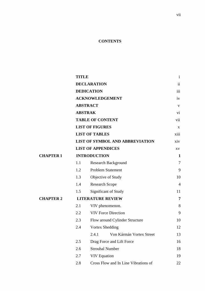
CONTENTS
TITLE i
DECLARATION ii
DEDICATION iii
ACKNOWLEDGEMENT iv
ABSTRACT v
ABSTRAK vi
TABLE OF CONTENT vii
LIST OF FIGURES x
LIST OF TABLES xiii
LIST OF SYMBOL AND ABBREVIATION xiv
LIST OF APPENDICES xv
CHAPTER 1 INTRODUCTION 1
1.1 Research Background 7
1.2 Problem Statement 9
1.3 Objective of Study 10
1.4 Research Scope 4
1.5 Significant of Study 11
CHAPTER 2 LITERATURE REVIEW 7
2.1 VIV phenomenon. 8
2.2 VIV Force Direction 9
2.3 Flow around Cylinder Structure 10
2.4 Vortex Shedding 12
2.4.1 Von Kármán Vortex Street 13
2.5 Drag Force and Lift Force 16
2.6 Strouhal Number 18
2.7 VIV Equation 19
2.8 Cross Flow and In Line Vibrations of 22

viii
Cylindrical Structure
2.9 Reynolds Number, Re 24
2.10 Navier Stokes Equation 27
2.11 Computational Fluid Dynamics (CFD) 28
2.12 Turbulence model 30
2:13 Turbulence modeling 32
CHAPTER 3 METHODOLOGY 32
3.1 Research Flow Chart 33
3.2 Problem Set-Up 35
3.3 Numerical Modelling 36
3.3.1 Domain Modelling 36
3.3.2 Meshing 38
3.3.3 Solver Setting 39
3.3.4 Material Properties 40
3.3.5 Boundary Condition 41
3.3.4 Dynamic Mesh parameters and 43
Zones
3.3.5 Solution Control 44
3.3.6 Monitoring Output 45
3.3.7 Determining the Cylinder Area 45
3.3.8 Iterate 46
CHAPTER 4 RESULTS AND DISCUSSION 45
4.1 Analysis on Flow around Circular Cylinder 46
4.1.1 Comparison with Others Work 48
Towards The Fluid Flow
4.2 VIV of Cylinder With One Degree of Freedom 49
4.2.1 The Effect of Frequency towards 50
The Fluid Flow
4.2.2 Effect of Amplitude towards 51
The Fluid Flow
4.23 Effect of Pressure Distribution 54
Towards The Fluid Flow
4.4 Vortex Shedding In The Wake 58

ix
CHAPTER 5 CONCLUSION AND RECOMMENDATIONS 611
5.1 Conclusion 610
5.2 Recommendations 63
REFERENCES 65
APPENDICES 70
x
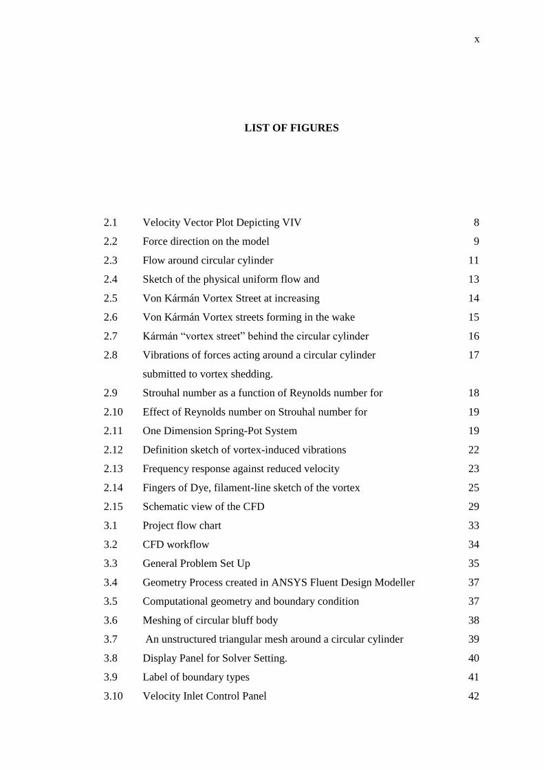
LIST OF FIGURES
2.1 Velocity Vector Plot Depicting VIV 8
2.2 Force direction on the model 9
2.3 Flow around circular cylinder 11
2.4 Sketch of the physical uniform flow and 13
2.5 Von Kármán Vortex Street at increasing 14
2.6 Von Kármán Vortex streets forming in the wake 15
2.7 Kármán “vortex street” behind the circular cylinder 16
2.8 Vibrations of forces acting around a circular cylinder 17
submitted to vortex shedding.
2.9 Strouhal number as a function of Reynolds number for 18
2.10 Effect of Reynolds number on Strouhal number for 19
2.11 One Dimension Spring-Pot System 19
2.12 Definition sketch of vortex-induced vibrations 22
2.13 Frequency response against reduced velocity 23
2.14 Fingers of Dye, filament-line sketch of the vortex 25
2.15 Schematic view of the CFD 29
3.1 Project flow chart 33
3.2 CFD workflow 34
3.3 General Problem Set Up 35
3.4 Geometry Process created in ANSYS Fluent Design Modeller 37
3.5 Computational geometry and boundary condition 37
3.6 Meshing of circular bluff body 38
3.7 An unstructured triangular mesh around a circular cylinder 39
3.8 Display Panel for Solver Setting. 40
3.9 Label of boundary types 41
3.10 Velocity Inlet Control Panel 42
xi
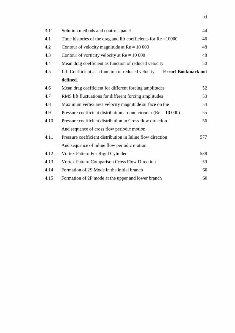
3.11 Solution methods and controls panel 44
4.1 Time histories of the drag and lift coefficients for Re =10000 46
4.2 Contour of velocity magnitude at Re = 10 000 48
4.3 Contour of vorticity velocity at Re = 10 000 48
4.4 Mean drag coefficient as function of reduced velocity. 50
4.5 Lift Coefficient as a function of reduced velocity Error! Bookmark not
defined.
4.6 Mean drag coefficient for different forcing amplitudes 52
4.7 RMS lift fluctuations for different forcing amplitudes 53
4.8 Maximum vertex area velocity magnitude surface on the 54
4.9 Pressure coefficient distribution around circular (Re = 10 000) 55
4.10 Pressure coefficient distribution in Cross flow direction 56
And sequence of cross flow periodic motion
4.11 Pressure coefficient distribution in Inline flow direction 577
And sequence of inline flow periodic motion
4.12 Vortex Pattern For Rigid Cylinder 588
4.13 Vortex Pattern Comparison Cross Flow Direction 59
4.14 Formation of 2S Mode in the initial branch 60
4.15 Formation of 2P mode at the upper and lower branch 60
xiii
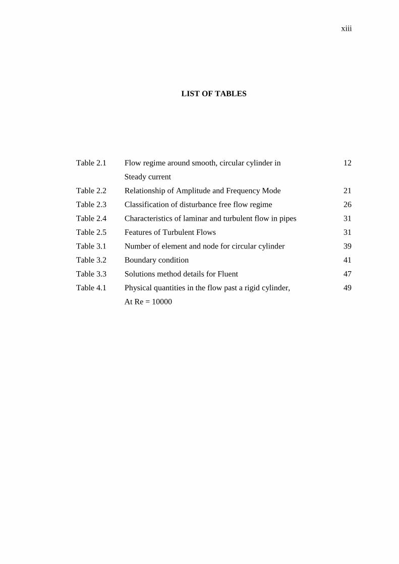
LIST OF TABLES
Table 2.1 Flow regime around smooth, circular cylinder in 12
Steady current
Table 2.2 Relationship of Amplitude and Frequency Mode 21
Table 2.3 Classification of disturbance free flow regime 26
Table 2.4 Characteristics of laminar and turbulent flow in pipes 31
Table 2.5 Features of Turbulent Flows 31
Table 3.1 Number of element and node for circular cylinder 39
Table 3.2 Boundary condition 41
Table 3.3 Solutions method details for Fluent 47
Table 4.1 Physical quantities in the flow past a rigid cylinder, 49
At Re = 10000
xiv
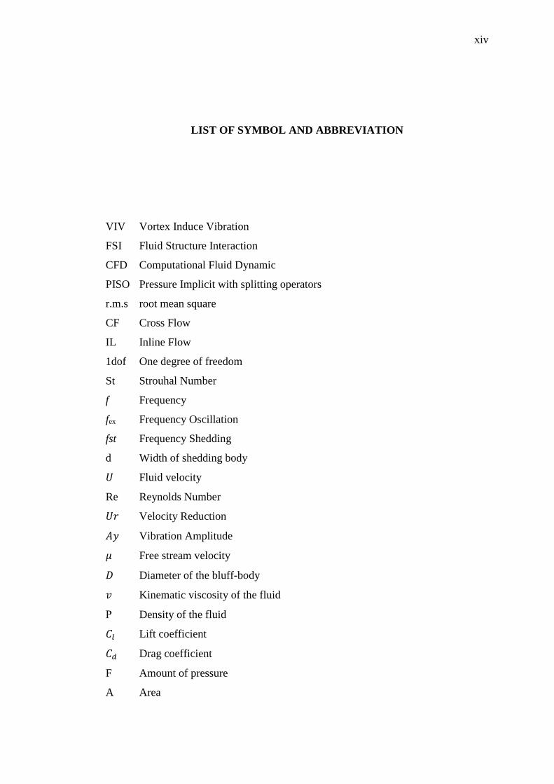
LIST OF SYMBOL AND ABBREVIATION
VIV Vortex Induce Vibration
FSI Fluid Structure Interaction
CFD Computational Fluid Dynamic
PISO Pressure Implicit with splitting operators
r.m.s root mean square
CF Cross Flow
IL Inline Flow
1dof One degree of freedom
St Strouhal Number
f Frequency
fex Frequency Oscillation
fst Frequency Shedding
d Width of shedding body
𝑈 Fluid velocity
Re Reynolds Number
𝑈𝑟 Velocity Reduction
𝐴𝑦 Vibration Amplitude
𝜇 Free stream velocity
𝐷 Diameter of the bluff-body
𝑣 Kinematic viscosity of the fluid
Ρ Density of the fluid
𝐶𝑙 Lift coefficient
𝐶𝑑 Drag coefficient
F Amount of pressure
A Area
xv
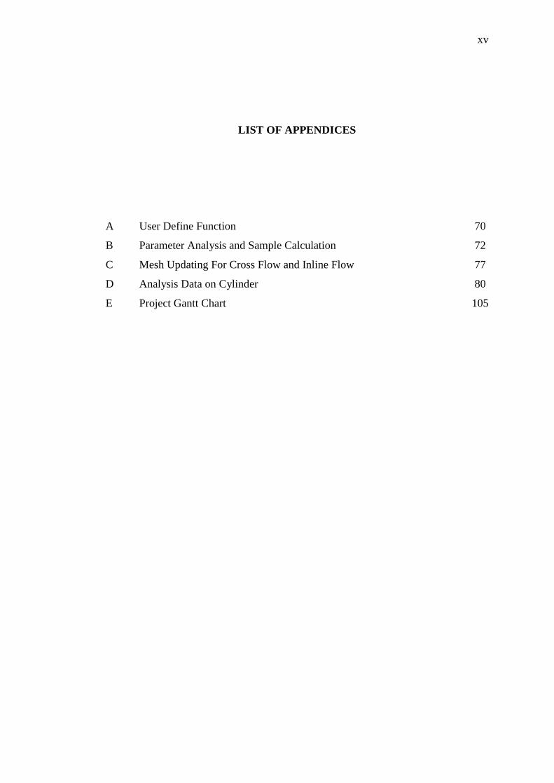
LIST OF APPENDICES
A User Define Function 70
B Parameter Analysis and Sample Calculation 72
C Mesh Updating For Cross Flow and Inline Flow 77
D Analysis Data on Cylinder 80
E Project Gantt Chart 105
CHAPTER 1
INTRODUCTION
1.1 Research Background
Vortex-induced vibrations of bluff bodies have been studied for a long time due to
their importance in both academic researches and engineering applications. The
prediction of offshore structures subjected to VIV is one of the most challenging
tasks since VIV is a subset of the broader field, the complicated fluid-structure
interaction (FSI) phenomenon is involved. For the purpose of understanding this
issue, numerous experimental and numerical simulation studies have been carried out
on this fluid-structure problem, often dealing with only one degree of freedom (1dof)
due to the difficulties and complexities associated mainly with VIV covering from
rigid cylinders studies to elastic structured cylinder. For instance, Zhang et.al. (2009)
confirms that VIV caused by vortex shedding from the cylinder is a typical fluid-
interaction problems.
Generally there are two types of motion involved in order to perform the
simulation either free induced motion or force induced motion. The phenomenon of
vortex shedding lock-in due to either forced or self-induced cylinder oscillations in
crossflow has been extensively studied over the past decades (Konstantinidis et.al.,
2003). According to Zhou et.al (1998), different experimental approach to investigate
FSI depending on the studies set out to be obtain. For example if the effects of
structural vibrations on the wake behavior are of interest only, the approached
8
adopted is to force the structure to vibrate usually in one direction at prescribe
amplitude and frequency.
According to Tang et.al (2013), several researcher pointing out experimental
works focused on high Reynolds numbers such as Feng (1968), Brika and Laneville
(1993) and Khalak and Williamson (1999) was among the first researchers to
investigate the VIV problem. Mittal and Kumar (1999), Shiels et al (2001) and
Plazeck et al (2009) among the namely few researchers carried out numerical
simulations of an elastically mounted circular cylinder subjected to VIV.
Observation by Pattel (2010) shows that flow is very sensitive to the changes
of Reynolds number, a dimensionless parameter representing the ratio of inertia force
to viscous force in a flow. The periodic flow force, generated by the periodic vortex
shedding, affect the cylinder vibration as well as the fluid flow around cylinder, the
fluid force and the vortex patterns ,thus forming the complex fluid-structure
interaction. Zhang et.al (2009) confirmed that flow induced vibration of an elastic
circular cylinder is a nonlinear case.
The VIV of cylinders bluff body influences the dynamics vibrations of
offshore riser tubes bringing oil from the seabed to the surface.as well as others,
submarine towed array cables and ship moorings in water as well as atmospheric
problems including smokestacks, cellular towers and buildings.
According to Michael (1994) the most essential VIV parameters are the lift
coefficient, the shedding frequency (Strouhal number), the correlation length, and the
shedding frequency bandwidth and are to be obtained from experimental model test.
Similarly, lock-on can also be observed when the cylinder is stationary and
the incident mean flow has a periodic component superimposed upon it (Barbi et al.,
1986; Armstrong et al., 1986; Hall and Griffin, 1993). This type of flow, termed
perturbed flow here, is equivalent to in-line oscillations of the cylinder in a steady
incident flow when the perturbation wavelength is large compared to the cylinder
diameter (Griffin and Hall, 1991)
There are several others of important parameters in determining VIV
response due to vortices. They are reduced velocity, the dimensionless amplitude is
the main parameter in performing experiment regarding vortex induce vibration.
Reduce velocity is a length of the path per cycle / diameter of the cylinder or can be
written as U/fex D where U is a flow velocity, fex is the frequency of oscillation of a
vibrating body and D is cylinder diameter (characteristic width). The Norwegian
9
Marine Research Institute (MARINTEK) concluded that among the drag effects of
VIV on marine risers are reducing fatigue life time, increase axial tension, increase
extreme loads and increase drag resistance.
Previous research had been conducted extensively to study the interaction
between vortices and structures. According to Song et al. (2011), majority of the
research is focused on rigid cylinders interaction instead of flexible structures. There
are few numerical simulation performed in finding VIV response with flexible
structures such as Bai et al. (2005).
The computational method is used to analyse a bluff body responses when
exposed into specific fluid flow condition. A model is developed using Fluent 15, an
application tools for fluid dynamics analysis from ANSYS Inc, whilst the principle
data and flow condition is taken from numerical simulation. Both results will be
compared to find dissimilarities as many discrepancies occur between measurements
and predictions from empirically based codes and CFD is always reported (Song et
al., 2011).
1.2 Problem Statement
Unsteady oscillatory phenomenon, which causes the pressure distribution around the
cylinders to fluctuate, resulting in forces perpendicular to the flow and bluff body
structure. These forces excite forced oscillations of the cylinder known as vortex-
induced vibrations. When the frequency of VIV approaches one of the natural
frequencies of the structure, the amplitude of vibration is enhanced through a
resonant phenomenon known as lock-in or synchronization of the wake. Lock-in and
oscillation frequencies can also take place when a cylinder oscillates in line with the
incident flow (Griffin and Ramberg, 1976; Ongoren and Rockwell, 1988)
Although the phenomenon of VIV of bluff bodies has been studied
extensively, the vast majority of previous studies have concentrated solely on
transverse vibrations since the fluctuating lift is the dominant force (Konstantinidis
et.al. 2003).Various response curves have been measured showing the amplitude,
frequency, and phase of cylinders undergoing VIV. However, since the fluctuating
forces responsible for these oscillations have unsteadiness in both lift and drag, the

10
role of stream wise vibrations cannot be ignored. To understand the relationship
between frequencies, amplitude, the motion of the cylinder as well as vortex
shedding flow, studies on the flow past a circular cylinder undergoing forced
vibration should be carried out.
1.3 Objective of Study
The objectives of this research are:
To investigate the effect of the frequency, amplitude, subjected to cross-line and in-
line motion of the bluff body on the flow velocity and pressure in the time response
(unsteady state).
1.4 Research Scope
The scopes can be listed as:
i. Develop the Computational Fluid Dynamics (CFD) model for the flow
simulation of a bluff body.
ii. Cross-sectional area of the bluff bodies 0.0079m2 for circular
iii. Shape is allow to move in in-line flow (X-direction) and cross-flow
(Y-direction)
iv. Test at frequency variation motion of the shape ranging from 1.39 Hz,
2.77 Hz and 3.0 Hz.
v. Test at amplitude variation motion of the shape ranging from 0.3m,
0.5m and 0.7m.
vi. Test at Reynolds number variation ranging between 10000 and
100000.

11
1.5 Significant of Study
The effect of circular cylinder oscillation in lateral (cross flow) and transverse
motion (inline flow) towards the flow profiles will be investigated using a
simulation. Addressing from low to high Reynolds numbers within the forcing
frequency of the structure will be varied accordingly at various values of amplitude
in order to analyze the difference. It is believed that such simulations are important
for understanding vortex induced vibrations, characterized by controlled oscillations.
The knowledge gained from this study later may contribute significantly to the
understanding of the VIV and for testing and validation of numerical simulations of
the flow around stationary and vibrating bluff bodies which are of great importance
in engineering structures especially cylindrical structures, such as subsea pipelines
and marine risers.
CHAPTER 2
LITERATURE REVIEW
This chapter introduces the background theories of CFD and the techniques for
solving fluid flow problems. Understanding CFD is important in investigating the
influences and impacts of fluid flow. The chapter consists of two main sections, by
outlines the governing mathematical equations for solving the turbulence models of
the flow around bluff bodies and roles of CFD in the study of fluid flow. In first
section, which is the major part of this chapter describes the basic concept of vortex
shedding and vortex induced vibrations are explained and previous research is
examined to illustrate the relevant parameters associated with vortex-induced
vibrations. Past simplifications in analysing vortex-induced vibrations are shown and
the relevant non-dimensional parameters for properly modelling and scaling the
forces associated with vortex induced vibrations are defined. The emphasis is given
to the last section of this chapter where the problem of mode ratio variation is
introduced with an explanation of the work performed by Dahl (2008).
Characteristics of bluff-body flows and important parameter that control such flows,
the Reynolds number, the Strouhal number, drag coefficient and lift coefficient, also
were discussed.
8
2.1 VIV phenomenon
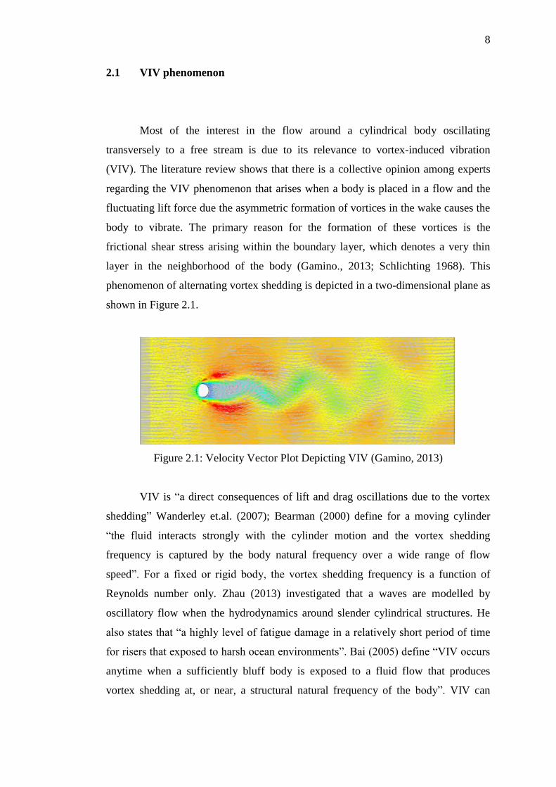
Most of the interest in the flow around a cylindrical body oscillating
transversely to a free stream is due to its relevance to vortex-induced vibration
(VIV). The literature review shows that there is a collective opinion among experts
regarding the VIV phenomenon that arises when a body is placed in a flow and the
fluctuating lift force due the asymmetric formation of vortices in the wake causes the
body to vibrate. The primary reason for the formation of these vortices is the
frictional shear stress arising within the boundary layer, which denotes a very thin
layer in the neighborhood of the body (Gamino., 2013; Schlichting 1968). This
phenomenon of alternating vortex shedding is depicted in a two-dimensional plane as
shown in Figure 2.1.
Figure 2.1: Velocity Vector Plot Depicting VIV (Gamino, 2013)
VIV is “a direct consequences of lift and drag oscillations due to the vortex
shedding” Wanderley et.al. (2007); Bearman (2000) define for a moving cylinder
“the fluid interacts strongly with the cylinder motion and the vortex shedding
frequency is captured by the body natural frequency over a wide range of flow
speed”. For a fixed or rigid body, the vortex shedding frequency is a function of
Reynolds number only. Zhau (2013) investigated that a waves are modelled by
oscillatory flow when the hydrodynamics around slender cylindrical structures. He
also states that “a highly level of fatigue damage in a relatively short period of time
for risers that exposed to harsh ocean environments”. Bai (2005) define “VIV occurs
anytime when a sufficiently bluff body is exposed to a fluid flow that produces
vortex shedding at, or near, a structural natural frequency of the body”. VIV can
9
occur with high dangerous amplitudes as the continuous periodic vibration of the
structure could make it susceptible to fatigue failure.
Computational fluid dynamics (CFD) simulations is presented as another
option as an alternative to response models can be applied for VIV assessment to
overcome the inherent limitations of the state-of-practice engineering approach
(Gamino, 2013).
Generally modelling VIV riser behavior is dependent on a number of
empirical parameter such as Strouhal number, correlation length and lift coefficient.
Other related flow parameter such as Reynolds number, surface roughness,
Keulegan- Carpenter number, and turbulent intensity. Commonly lift coefficient and
Strouhal number is the most of the tests provide data for all parameter
2.2 VIV Force Direction
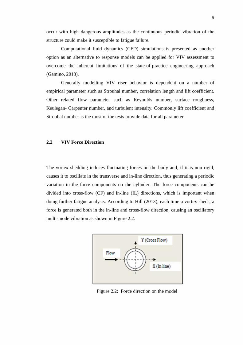
The vortex shedding induces fluctuating forces on the body and, if it is non-rigid,
causes it to oscillate in the transverse and in-line direction, thus generating a periodic
variation in the force components on the cylinder. The force components can be
divided into cross-flow (CF) and in-line (IL) directions, which is important when
doing further fatigue analysis. According to Hill (2013), each time a vortex sheds, a
force is generated both in the in-line and cross-flow direction, causing an oscillatory
multi-mode vibration as shown in Figure 2.2.
Figure 2.2: Force direction on the model
10
Consequently, as vortices are being shed on the cylinder surface, the cylinder
experiences forces which are periodic in nature. These forces cause the cylinder to
continuously vibrate as long as vortices are shed. Chakrabarti, (2005) listed that
important hydrodynamic quantities that influence VIV are: Reynolds number, lift
coefficient, correlation of force components, shedding frequencies and their
interactions, added mass or mass ratio and damping
Dynamic force in CF (transverse) direction to the flow due to vortices
reactions is referred to lift force. Transverse cylinder vibration has a large effect on
vortex shedding. The correlation of vortex shedding along the cylinder axis increases
by transverse cylinder vibration. Increased transverse vibration amplitude (Ay) also
increases the ability of the vibration to lock in or synchronize the shedding frequency
(Blevins, 2001).
According to Michael (1994), when motion of the cylinder organizes the
wake and cause the shedding frequency to abruptly jump from its nominal value fst to
a value equal to the oscillation frequency, fex, the shedding frequency said to be in
locked-in, locked on or synchronized to the cylinder frequency. The first
phenomenon reported by Bishop in 1964.
Vortices shed far from the cylinder when cylinder vibration near to its
maximum displacement. Zdravkovic (1982) agrees that the vortex is shed from the
side opposite the side experiencing maximum displacement when vibration
frequency is below the natural shedding frequency and vortex is shed from the same
side as the maximum displacement when vibration frequency above the shedding
frequency (Blevins, 2001).
Stansby (1979) found that in several key point regarding lock-in
phenomenon including shedding behavior at the edges of the lock-in frequency range
is similar for uniform and shear flow while the minimum amplitude to ignite lock-in
is increase with the increase of Re.
2.3 Flow around Cylinder Structure
When a fluid flow past a bluff body, in this case, a cylindrical structure whose
direction is perpendicular to the axis of the bluff- body such as cross-flow ,Cl the
11
bluff-body structure will try to vibrate in a direction normal to the flow direction
(Akaydin et.al 2010). This flow induced vibration configuration is controlled by the
Reynolds number (Re), could be caused by the turbulence generated by the flow
around and in the wake of the cylinder.
When sufficiently large Reynolds number (Re) exceeds a critical value,
somehow the cylinder might experience excitations or vibrations, as the unsteady
flow around the cylinder separates from a wider section of the body giving rise to
periodic vortex shedding from either side of the body, forming pressure differences
causing a net force exerted on the bluff-body in the direction perpendicular to the
flow and creating vortices in a repeating of swirling vortices known as the von
Karman vortex street.
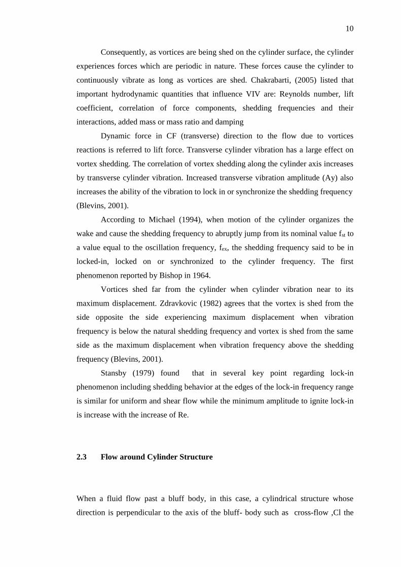
Flow patterns around of bluff bodies under either steady or turbulent ongoing
flows have been formed by either 1 shear layer or 2 shear layers on one side or both
sides of bodies due to the flow-body interactions depends on characteristics of bluff
bodies by means sectional shape and dimension and characteristics of ongoing flow
such as steady or unsteady, wind velocity, attack angle and even in-flow movement
of body, the around-body flow shear layer can be either stability or instability (Hoa,
2005).
Figure 2.3: Flow around circular cylinder (Gamino, 2013)
12
2.4 Vortex Shedding
Reynolds (1883) was the first to propose a criterion for differentiation between
laminar and turbulent flows in his classic dye visualization and suggested a critical
value of for the upper limit of laminar flow. In a second paper in 1895, he showed by
time-averaging the Navier-Stokes equations that new extra convection terms
appeared in turbulence which have the units of stress and are therefore called
Reynolds stresses.
Theodore von Kármán is the person who first stimulated widespread interest
and published the first theoretical study of vortex streets in 1911. In 1981 Schatzman,
who studied the analysis of a model for the Von Kármán Vortex Street found that the
linear stability of the point vortex has been generalized to vortices of finite size and
can stabilize the array (Azman, 2008).The vortex shedding around bluff bodies can
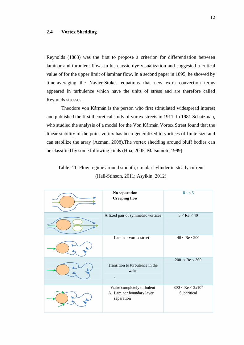
be classified by some following kinds (Hoa, 2005; Matsumoto 1999):
Table 2.1: Flow regime around smooth, circular cylinder in steady current
(Hall-Stinson, 2011; Asyikin, 2012)
No separation
Creeping flow
Re < 5
A fixed pair of symmetric vortices
5 < Re < 40
Laminar vortex street
40 < Re <200
Transition to turbulence in the
wake
.
200 < Re < 300
Wake completely turbulent
A. Laminar boundary layer
separation
300 < Re < 3x10⁵
Subcritical

13
(Continued)
A Laminar boundary
layer
separation
B. Turbulent boundary
layer separation: the
boundary layer partly
laminar partly
turbulent
3x10⁵ < Re < 3.5x10⁵
Critical (Lower transition)
B. Turbulent boundary layer
separation: the boundary
layer partly laminar
partly turbulent
3.5x10⁵ < Re < 1.5x10⁶
Supercritical
C. Boundary layer
completely turbulent at
one side
1.5 x 10⁶ < Re < 4 x10⁶
Upper transition
C. Boundary layer
completely turbulent at
two sides
4 x l06 < Re
Trans critical
2.4.1 Von Kármán Vortex Street
Numerous numerical and empirical methods have been studied in the analysis of
uniform flow past a rigid 2D cylinder. One of the parameters engineers study is the
formation of vortices behind the cylinders wake, which is illustrated in Figure 2.4:
Flow
Velocity Cylinder’s
wake
Figure 2.4: Sketch of the physical uniform flow and
the location of the cylinder’s wake
14
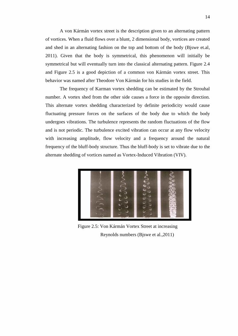
A von Kármán vortex street is the description given to an alternating pattern
of vortices. When a fluid flows over a blunt, 2 dimensional body, vortices are created
and shed in an alternating fashion on the top and bottom of the body (Bjswe et.al,
2011). Given that the body is symmetrical, this phenomenon will initially be
symmetrical but will eventually turn into the classical alternating pattern. Figure 2.4
and Figure 2.5 is a good depiction of a common von Kármán vortex street. This
behavior was named after Theodore Von Kármán for his studies in the field.
The frequency of Karman vortex shedding can be estimated by the Strouhal
number. A vortex shed from the other side causes a force in the opposite direction.
This alternate vortex shedding characterized by definite periodicity would cause
fluctuating pressure forces on the surfaces of the body due to which the body
undergoes vibrations. The turbulence represents the random fluctuations of the flow
and is not periodic. The turbulence excited vibration can occur at any flow velocity
with increasing amplitude, flow velocity and a frequency around the natural
frequency of the bluff-body structure. Thus the bluff-body is set to vibrate due to the
alternate shedding of vortices named as Vortex-Induced Vibration (VIV).
Figure 2.5: Von Kármán Vortex Street at increasing
Reynolds numbers (Bjswe et al.,2011)
15
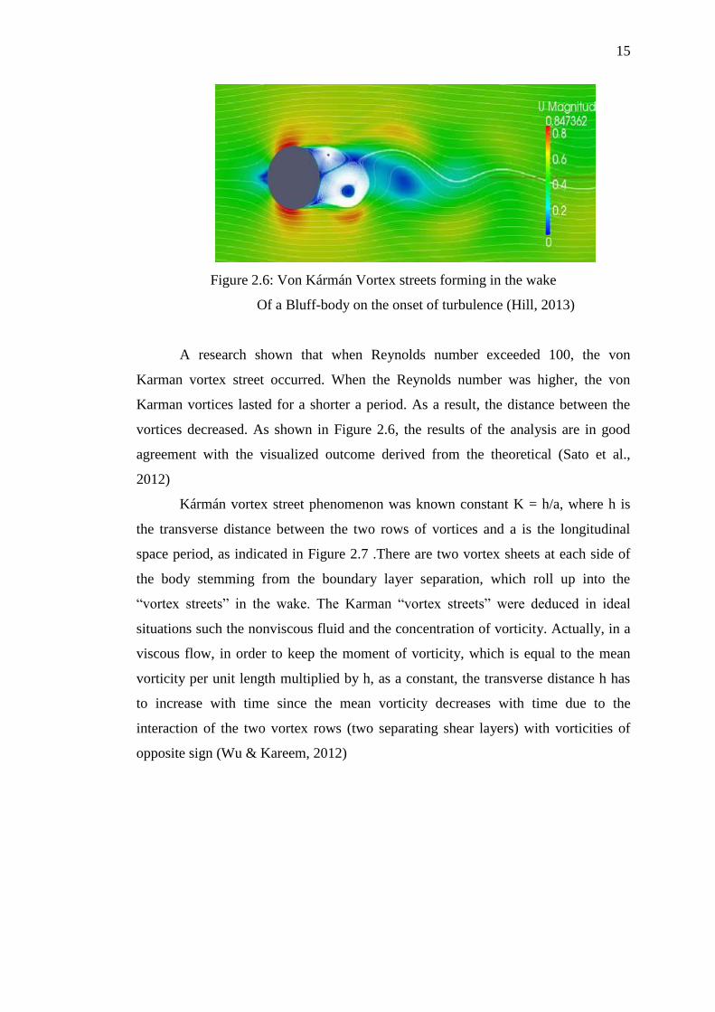
Figure 2.6: Von Kármán Vortex streets forming in the wake
Of a Bluff-body on the onset of turbulence (Hill, 2013)
A research shown that when Reynolds number exceeded 100, the von
Karman vortex street occurred. When the Reynolds number was higher, the von
Karman vortices lasted for a shorter a period. As a result, the distance between the
vortices decreased. As shown in Figure 2.6, the results of the analysis are in good
agreement with the visualized outcome derived from the theoretical (Sato et al.,
2012)
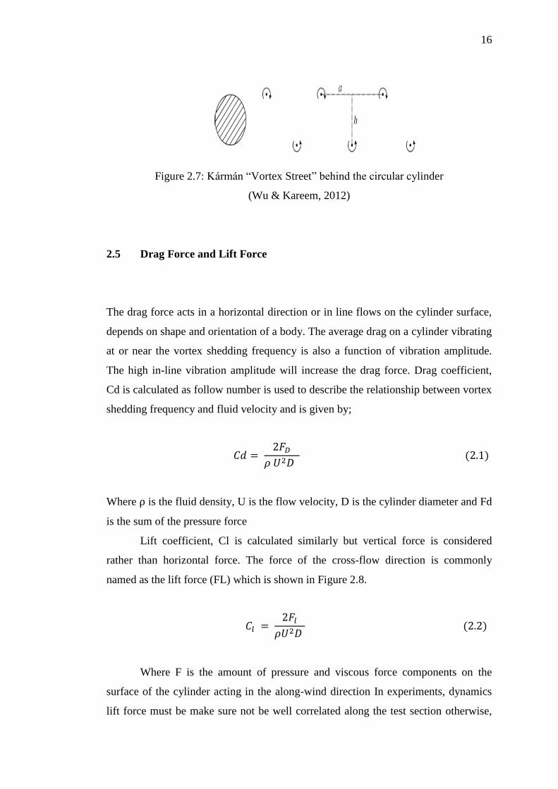
Kármán vortex street phenomenon was known constant K = h/a, where h is
the transverse distance between the two rows of vortices and a is the longitudinal
space period, as indicated in Figure 2.7 .There are two vortex sheets at each side of
the body stemming from the boundary layer separation, which roll up into the
“vortex streets” in the wake. The Karman “vortex streets” were deduced in ideal
situations such the nonviscous fluid and the concentration of vorticity. Actually, in a
viscous flow, in order to keep the moment of vorticity, which is equal to the mean
vorticity per unit length multiplied by h, as a constant, the transverse distance h has
to increase with time since the mean vorticity decreases with time due to the
interaction of the two vortex rows (two separating shear layers) with vorticities of
opposite sign (Wu & Kareem, 2012)
16
Figure 2.7: Kármán “Vortex Street” behind the circular cylinder
(Wu & Kareem, 2012)
2.5 Drag Force and Lift Force
The drag force acts in a horizontal direction or in line flows on the cylinder surface,
depends on shape and orientation of a body. The average drag on a cylinder vibrating
at or near the vortex shedding frequency is also a function of vibration amplitude.
The high in-line vibration amplitude will increase the drag force. Drag coefficient,
Cd is calculated as follow number is used to describe the relationship between vortex
shedding frequency and fluid velocity and is given by;
𝐶𝑑 = 2𝐹𝐷
𝜌 𝑈2𝐷 (2.1)
Where ⍴ is the fluid density, U is the flow velocity, D is the cylinder diameter and Fd
is the sum of the pressure force
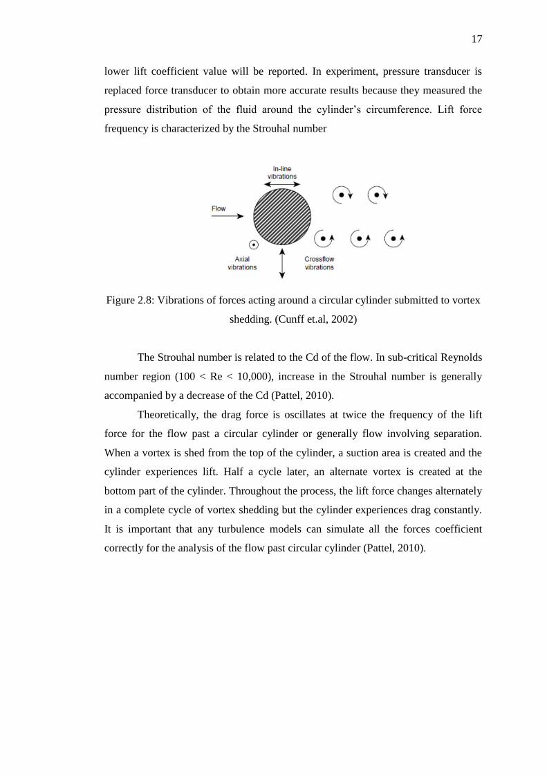
Lift coefficient, Cl is calculated similarly but vertical force is considered
rather than horizontal force. The force of the cross-flow direction is commonly
named as the lift force (FL) which is shown in Figure 2.8.
𝐶𝑙 = 2𝐹𝑙
𝜌𝑈2𝐷 (2.2)
Where F is the amount of pressure and viscous force components on the
surface of the cylinder acting in the along-wind direction In experiments, dynamics
lift force must be make sure not be well correlated along the test section otherwise,
17
lower lift coefficient value will be reported. In experiment, pressure transducer is
replaced force transducer to obtain more accurate results because they measured the
pressure distribution of the fluid around the cylinder’s circumference. Lift force
frequency is characterized by the Strouhal number
Figure 2.8: Vibrations of forces acting around a circular cylinder submitted to vortex
shedding. (Cunff et.al, 2002)
The Strouhal number is related to the Cd of the flow. In sub-critical Reynolds
number region (100 < Re < 10,000), increase in the Strouhal number is generally
accompanied by a decrease of the Cd (Pattel, 2010).
Theoretically, the drag force is oscillates at twice the frequency of the lift
force for the flow past a circular cylinder or generally flow involving separation.
When a vortex is shed from the top of the cylinder, a suction area is created and the
cylinder experiences lift. Half a cycle later, an alternate vortex is created at the
bottom part of the cylinder. Throughout the process, the lift force changes alternately
in a complete cycle of vortex shedding but the cylinder experiences drag constantly.
It is important that any turbulence models can simulate all the forces coefficient
correctly for the analysis of the flow past circular cylinder (Pattel, 2010).

18
2.6 Strouhal Number
The Strouhal number depends on Reynolds number, shape and dimension of body,
and wind or water velocities. The increasing of Reynolds number will affect Strouhal
number increases or decreases in certain range of Reynolds number. The increasing
size or dimension (D) will increase the Strouhal number, the increasing of velocity
(U) and change of attack angle will decreasing the Strouhal number (Hoa, 2005). It
should be noted that the Strouhal number can be influenced by the Reynolds number
in some cases, for circular cylinders, the Strouhal number seems to stay constant on
the certain range of Reynolds number between 1.5x10² and 1.5x10⁵ (Hoa, 2005,
Blevin 1977, Simui&Scanlan 1978).
Figure 2.9: Strouhal number as a function of Reynolds number for
Smooth circular cylinder (Hall-Stinson, 2011)
19
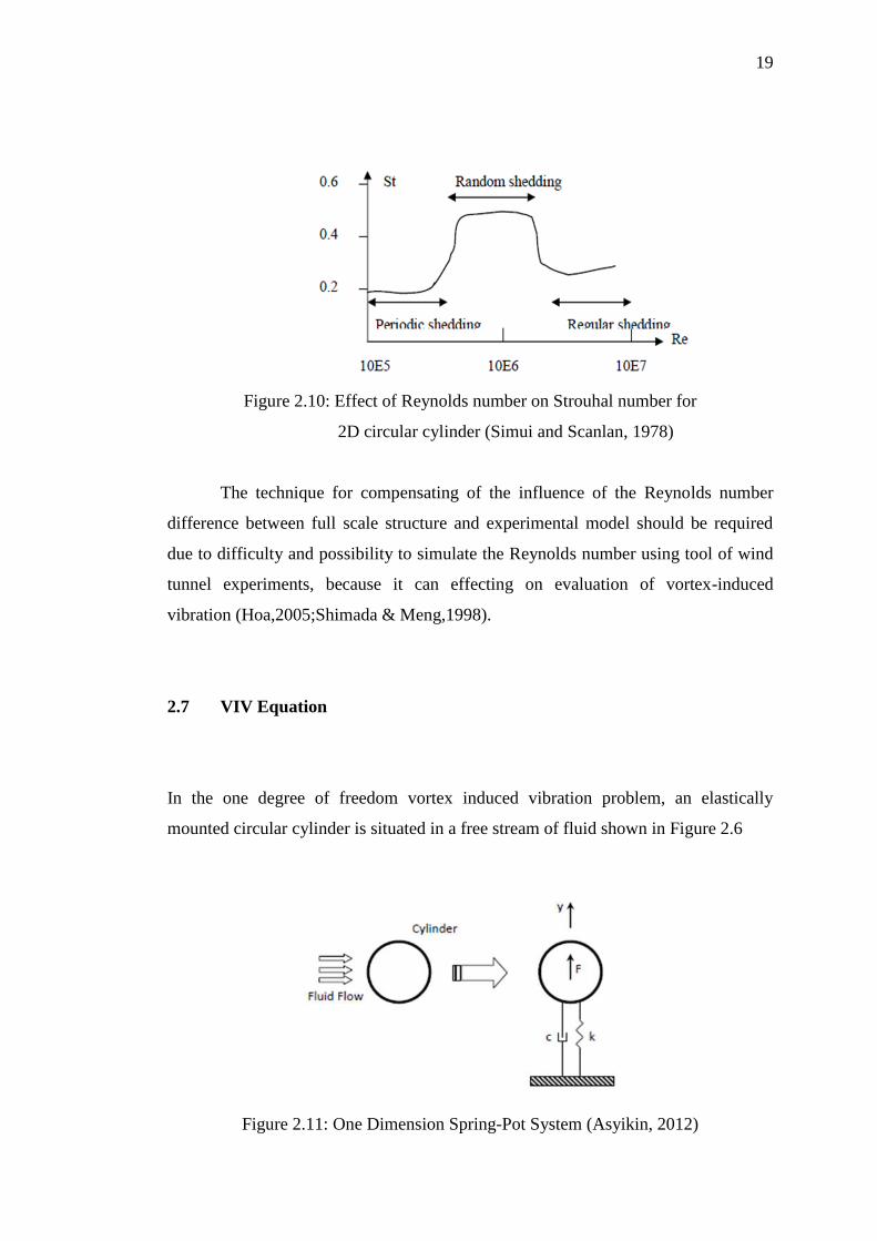
Figure 2.10: Effect of Reynolds number on Strouhal number for
2D circular cylinder (Simui and Scanlan, 1978)
The technique for compensating of the influence of the Reynolds number
difference between full scale structure and experimental model should be required
due to difficulty and possibility to simulate the Reynolds number using tool of wind
tunnel experiments, because it can effecting on evaluation of vortex-induced
vibration (Hoa,2005;Shimada & Meng,1998).
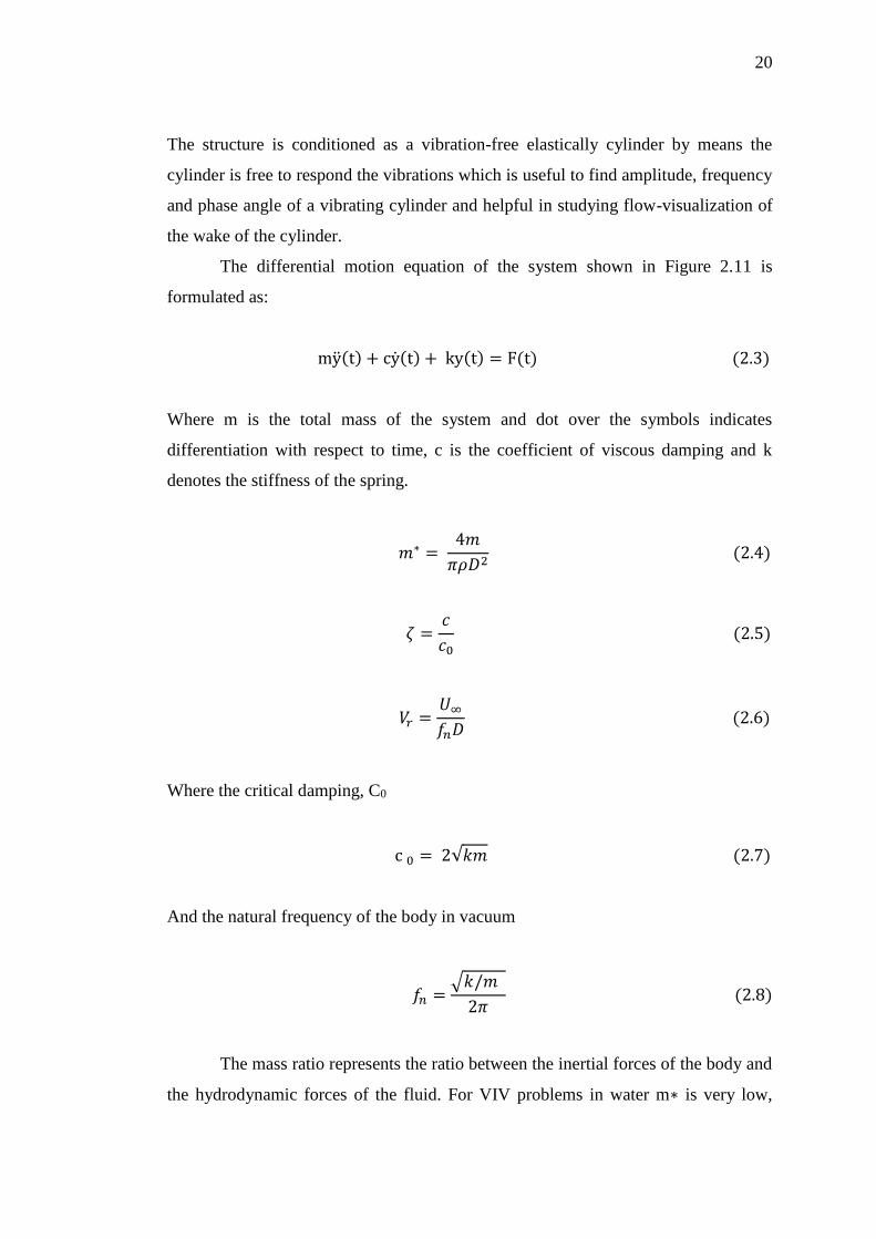
2.7 VIV Equation
In the one degree of freedom vortex induced vibration problem, an elastically
mounted circular cylinder is situated in a free stream of fluid shown in Figure 2.6
Figure 2.11: One Dimension Spring-Pot System (Asyikin, 2012)
20
The structure is conditioned as a vibration-free elastically cylinder by means the
cylinder is free to respond the vibrations which is useful to find amplitude, frequency
and phase angle of a vibrating cylinder and helpful in studying flow-visualization of
the wake of the cylinder.
The differential motion equation of the system shown in Figure 2.11 is
formulated as:
my(t) + cy(t) + ky(t) = F(t) (2.3)
Where m is the total mass of the system and dot over the symbols indicates
differentiation with respect to time, c is the coefficient of viscous damping and k
denotes the stiffness of the spring.
𝑚∗ = 4𝑚
𝜋𝜌𝐷2 (2.4)
𝜁 =𝑐
𝑐0 (2.5)
𝑉𝑟 =𝑈∞
𝑓𝑛𝐷 (2.6)
Where the critical damping, C0
c 0 = 2√𝑘𝑚 (2.7)
And the natural frequency of the body in vacuum
𝑓𝑛 =√𝑘/𝑚
2𝜋 (2.8)
The mass ratio represents the ratio between the inertial forces of the body and
the hydrodynamic forces of the fluid. For VIV problems in water m∗ is very low,
21
while in air it is usually one or two orders of magnitude larger. The excitation
frequency in air has generally a value similar to the frequency of the cylinder’s
response close to the body natural frequency fn.
The synchronization of vortex shedding and the body frequency takes place
over a range of reduced velocities, whose width is proportional to the oscillation
amplitude.
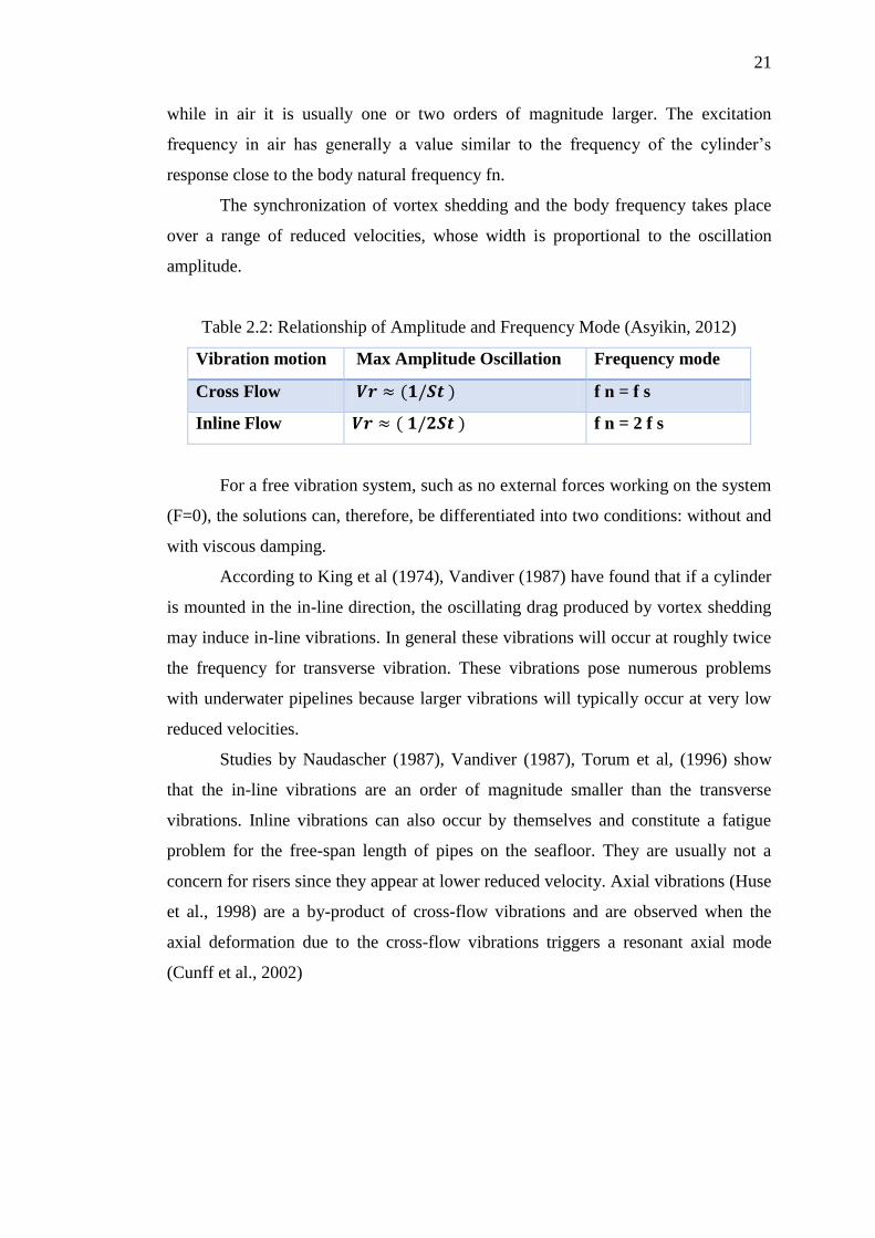
Table 2.2: Relationship of Amplitude and Frequency Mode (Asyikin, 2012)
For a free vibration system, such as no external forces working on the system
(F=0), the solutions can, therefore, be differentiated into two conditions: without and
with viscous damping.
According to King et al (1974), Vandiver (1987) have found that if a cylinder
is mounted in the in-line direction, the oscillating drag produced by vortex shedding
may induce in-line vibrations. In general these vibrations will occur at roughly twice
the frequency for transverse vibration. These vibrations pose numerous problems
with underwater pipelines because larger vibrations will typically occur at very low
reduced velocities.
Studies by Naudascher (1987), Vandiver (1987), Torum et al, (1996) show
that the in-line vibrations are an order of magnitude smaller than the transverse
vibrations. Inline vibrations can also occur by themselves and constitute a fatigue
problem for the free-span length of pipes on the seafloor. They are usually not a
concern for risers since they appear at lower reduced velocity. Axial vibrations (Huse
et al., 1998) are a by-product of cross-flow vibrations and are observed when the
axial deformation due to the cross-flow vibrations triggers a resonant axial mode
(Cunff et al., 2002)
Vibration motion Max Amplitude Oscillation Frequency mode
Cross Flow 𝑽𝒓 ≈ (𝟏/𝑺𝒕 ) f n = f s
Inline Flow 𝑽𝒓 ≈ ( 𝟏/𝟐𝑺𝒕 ) f n = 2 f s
22
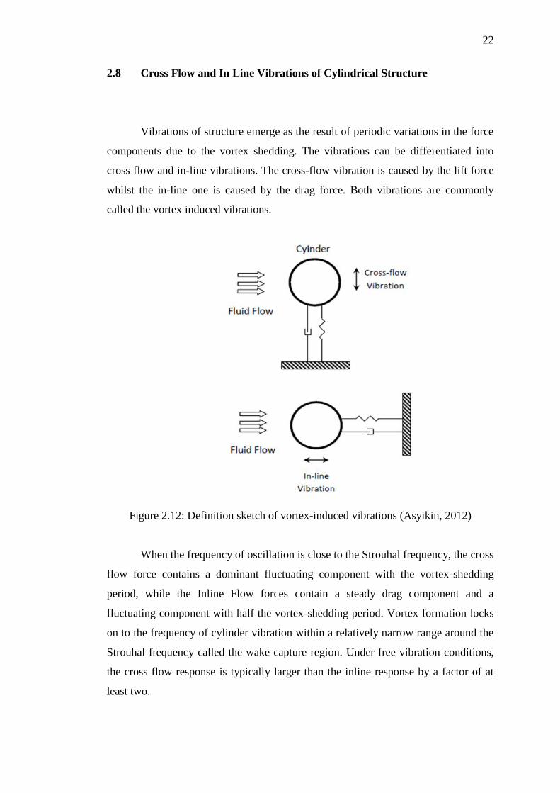
2.8 Cross Flow and In Line Vibrations of Cylindrical Structure
Vibrations of structure emerge as the result of periodic variations in the force
components due to the vortex shedding. The vibrations can be differentiated into
cross flow and in-line vibrations. The cross-flow vibration is caused by the lift force
whilst the in-line one is caused by the drag force. Both vibrations are commonly
called the vortex induced vibrations.
Figure 2.12: Definition sketch of vortex-induced vibrations (Asyikin, 2012)
When the frequency of oscillation is close to the Strouhal frequency, the cross
flow force contains a dominant fluctuating component with the vortex-shedding
period, while the Inline Flow forces contain a steady drag component and a
fluctuating component with half the vortex-shedding period. Vortex formation locks
on to the frequency of cylinder vibration within a relatively narrow range around the
Strouhal frequency called the wake capture region. Under free vibration conditions,
the cross flow response is typically larger than the inline response by a factor of at
least two.
23
A bluff body undergoes perfect vortex-shedding resonance if its inline natural
frequency (fx) is twice the transverse natural frequency (fy), and the Strouhal
frequency is near or at the transverse natural frequency, resulting in fluid excited
motions in both inline and transverse directions ( Dahl et al, 2007 ).
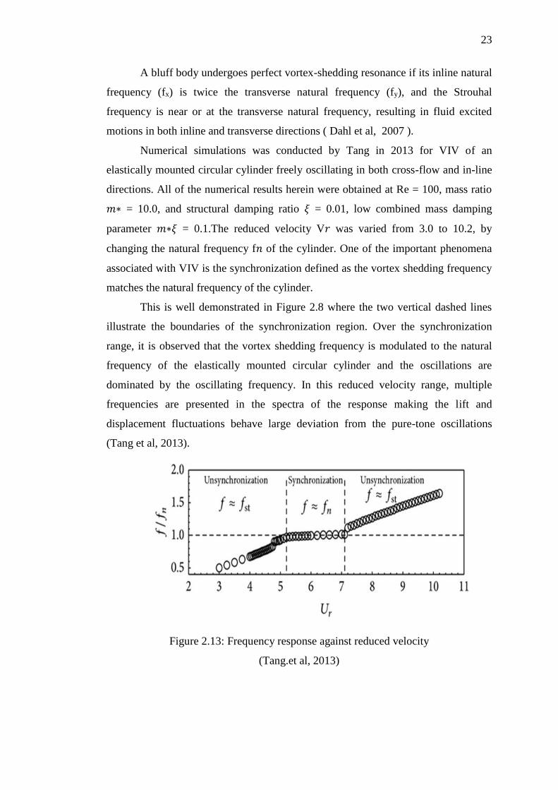
Numerical simulations was conducted by Tang in 2013 for VIV of an
elastically mounted circular cylinder freely oscillating in both cross-flow and in-line
directions. All of the numerical results herein were obtained at Re = 100, mass ratio
𝑚∗ = 10.0, and structural damping ratio 𝜉 = 0.01, low combined mass damping
parameter 𝑚∗𝜉 = 0.1.The reduced velocity V𝑟 was varied from 3.0 to 10.2, by
changing the natural frequency f𝑛 of the cylinder. One of the important phenomena
associated with VIV is the synchronization defined as the vortex shedding frequency
matches the natural frequency of the cylinder.
This is well demonstrated in Figure 2.8 where the two vertical dashed lines
illustrate the boundaries of the synchronization region. Over the synchronization
range, it is observed that the vortex shedding frequency is modulated to the natural
frequency of the elastically mounted circular cylinder and the oscillations are
dominated by the oscillating frequency. In this reduced velocity range, multiple
frequencies are presented in the spectra of the response making the lift and
displacement fluctuations behave large deviation from the pure-tone oscillations
(Tang et al, 2013).
Figure 2.13: Frequency response against reduced velocity
(Tang.et al, 2013)
24
2.9 Reynolds Number, Re
The flow around a stationary smooth circular cylinder depends on Re, one of the non
dimensionless hydrodynamic numbers that is accounted, denotes the relationship
between inertia forces and the viscous forces in the boundary layer and is categorized
roughly by four regimes which is subcritical, critical, supercritical and trans critical.
In 1833, one of the earliest research by Osborne Reynolds was the first to
systematically investigate the transition from laminar to turbulent flow by injecting a
dye streak into flow through a pipe having smooth transparent walls. His
observations led to identification of a single dimensionless parameter, now called the
Reynolds number, and denoted Re
Re = Inertia Force
Friction Force=
𝜌𝑈𝐷
𝜇 =
𝑈𝐷
𝜈 (2.9)
Where ρ is fluid density, µ is dynamic viscosity, D- is the cylinder diameter, and U is
the fluid velocity. One of the reasons that the Reynolds number is so important is that
its value determines the type of flow around a bluff body.
In 2001 Blevins shows that the composition of the vortex pattern from the
bluff body will change depending on Reynolds number. The experiments examined
here are in the regime where the vortex street is the fully turbulent and include
examples up to a Reynolds number of 3.5 ×10⁵ (Swithenbank et.al, 2008). He
proposed a crude division of the flow regimes is given by:
• 300 < Re < 1.5 ×10⁵ Subcritical regime
• 1.5 ×10⁵ < Re < 3.5 ×10⁵Transitional regime
• Re >3.5 ×10⁵Supercritical regime
One should be aware that the division of flow regimes into Reynolds number
ranges is not definite. Disturbances may have a profound effect on the flow and
change the rearranges for where the various regimes are seen also influenced the
65
REFERENCES
Akhavan, R., Kamm, R. D., & Shapiro, A. H. (1991). An investigation of transition
to turbulence in bounded oscillatory Stokes flows Part 2. Numerical
simulations. Journal of Fluid Mechanics, 225, 423-444.
Asyikin, M. T. (2012). CFD Simulation of Vortex Induced Vibration of a Cylindrical
Structure.
Bearman, P. W. (2009). Understanding and predicting vortex-induced vibrations.
Journal of Fluid Mechanics, 634, 1-4.
Bearman, P. W. (2011). Circular cylinder wakes and vortex-induced vibrations.
Journal of Fluids and Structures, 27(5), 648-658.
Bershader, D. (1981). 9.3. Low Reynolds Number Flows. Methods of Experimental
Physics, 18, 796-801.
Blevins, R. D., & Coughran, C. S. (2009). Experimental investigation of vortex-
induced vibration in one and two dimensions with variable mass, damping, and
Reynolds number. Journal of Fluids Engineering, 131(10), 101202.
Bourguet, R., & Triantafyllou, M. S. (2015). Vortex-induced vibrations of a flexible
cylinder at large inclination angle. Philosophical Transactions of the Royal
Society of London A: Mathematical, Physical and Engineering Sciences,
373(2033), 20140108.
Dahl, J. M., Hover, F. S., Triantafyllou, M. S., Dong, S., & Karniadakis, G. E.
(2007). Resonant vibrations of bluff bodies cause multivortex shedding and high
frequency forces. Physical review letters, 99(14), 144503.
De Vecchi, A., Sherwin, S. J., & Graham, J. M. R. (2009). Wake dynamics past a
curved body of circular cross-section under forced cross-flow vibration. Journal
of Fluids and Structures, 25(4), 721-730.
Dowell, E. H., Hall, K. C., Thomas, J. P., Kielb, R. E., Spiker, M. A., & Denegri Jr,
C. M. (2008, January). A new solution method for unsteady flows around
oscillating bluff bodies. In IUTAM Symposium on Fluid-Structure Interaction
in Ocean Engineering (pp. 37-44). Springer Netherlands.
66
Bjswe, P., Johnson, B., & Phinney, B. Optimization of Oscillating Body for Vortex
Induced Vibrations. Worcester Polytechnic Institute; 2010.
Gabbai, R. D., & Benaroya, H. (2005). An overview of modeling and experiments of
vortex-induced vibration of circular cylinders. Journal of Sound and Vibration,
282(3), 575-616.
Gamino, M., Abankwa, S., & Pascali, R. (2013, June). FSI Methodology for
Analyzing VIV on Subsea Piping Components With Practical Boundary
Conditions. In ASME 2013 32nd International Conference on Ocean, Offshore
and Arctic Engineering (pp. V007T08A028-V007T08A028). American Society
of Mechanical Engineers.
Hall-Stinson, A. (2011). Energy Generation From Vortex Induced Vibrations
(Doctoral dissertation, Worcester Polytechnic Institute).
Haworth, D. C. (2005). A review of turbulent combustion modeling for
multidimensional In-Cylinder CFD (No. 2005-01-0993). SAE Technical Paper
Jauvtis, N., & Williamson, C. H. K. (2003). Vortex-induced vibration of a cylinder
with two degrees of freedom. Journal of Fluids and Structures, 17(7), 1035-
1042.
1Jauvtis, N., & Williamson, C. H. K. (2004). The effect of two degrees of freedom
on vortex-induced vibration at low mass and damping. Journal of Fluid
Mechanics, 509, 23-62.
Kim, S., Wilson, P. A., & Chen, Z. M. (2014). Numerical simulation of force and
wake mode of an oscillating cylinder. Journal of Fluids and Structures, 44, 216-
225.
Kocabiyik, S., & Nguyen, P. (1998). On a translating and transversely oscillating
cylinder: Part 2: Effect of the velocity ratio on the hydrodynamic forces and the
near-wake structure. Ocean engineering, 26(1), 21-45.
Kumar, S., Lopez, C., Probst, O., Francisco, G., Askari, D., & Yang, Y. (2013). Flow
past a rotationally oscillating cylinder. Journal of Fluid Mechanics, 735, 307-
346.
Liaw, K. (2005). Simulation of flow around bluff bodies and bridge deck sections
using CFD (Doctoral dissertation, University of Nottingham).
Le Cunff, C., Biolley, F., Fontaine, E., Etienne, S., & Facchinetti, M. L. (2002).
Vortex-induced vibrations of risers: theoretical, numerical and experimental
investigation. Oil & Gas Science and Technology, 57(1), 59-69
Lee, S. J., & Lee, J. Y. (2006). Flow structure of wake behind a rotationally
oscillating circular cylinder. Journal of fluids and structures, 22(8), 1097-1112.

67
Lee, S. J., & Lee, J. Y. (2008). PIV measurements of the wake behind a rotationally
oscillating circular cylinder. Journal of Fluids and Structures, 24(1), 2-17.
Mastenbroek, J. J. (2010). Bluff body flow: wake behavior behind a heated circular
cylindeer.Kulkarni, A. A., Harne, M. S., & Bachal, A. (2014). Study of Vortex
Shedding Behind Trapezoidal Bluff Body by Flow Visualization Method. In
International Journal of Engineering Research and Technology (Vol. 3, No. 9
(September-2014)). ESRSA Publications.
Mittal, S., & Kumar, V. (2001). Flow-induced oscillations of two cylinders in
tandem and staggered arrangements. Journal of Fluids and Structures, 15(5),
717-736.
Michael, S. P. (1994). Vortex induced vibration parameters: critical review. OMAE
Offshore Technology.
Nguyen, P., & Kocabiyik, S. (1997). On a translating and transversely oscillating
cylinder. Part 1—The effect of the strouhal number on the hydrodynamic forces
and the near-wake structure. Ocean engineering, 24(8), 677-693.
Patel, Y. (2010). Numerical investigation of flow past a circular cylinder and in a
staggered tube bundle using various turbulence models.
Resvanis, T. L., Jhingran, V., Vandiver, J. K., & Liapis, S. (2012, July). Reynolds
number effects on the vortex-induced vibration of flexible marine risers. In
ASME 2012 31st International Conference on Ocean, Offshore and Arctic
Engineering (pp. 751-760). American Society of Mechanical Engineers.
Rhie, C. M., & Chow, W. L. (1983). Numerical study of the turbulent flow past an
airfoil with trailing edge separation. AIAA journal, 21(11), 1525-1532.
Samarbakhsh, S. (2014). Investigation of the Lock-in behavior of an eccentrically
rotating cylinder in regard to turbomachinery application.
Sanchis, A., Saelevik, G., & Grue, J. (2008). Two-degree-of-freedom vortex-induced
vibrations of a spring-mounted rigid cylinder with low mass ratio. Journal of
Fluids and Structures, 24(6), 907-919
Sato, M., & Kobayashi, T. (2012). A fundamental study of the flow past a circular
cylinder using Abaqus/CFD. In 2012 SIMULIA Community Conference.
Sellappan, P., & Pottebaum, T. (2014). Vortex shedding and heat transfer in
rotationally oscillating cylinders. Journal of Fluid Mechanics, 748, 549-579
Song, J. N., Lu, L., Teng, B., Park, H. I., Tang, G. Q., & Wu, H. (2011). Laboratory
tests of vortex-induced vibrations of a long flexible riser pipe subjected to
uniform flow. Ocean Engineering, 38(11), 1308-1322.
68
Srinil, N., Zanganeh, H., & Day, A. (2013). Two-degree-of-freedom VIV of circular
cylinder with variable natural frequency ratio: Experimental and numerical
investigations. Ocean Engineering, 73, 179-194.
Stavropoulos, M., Charlesworth, D., & Dixon, M. (2005). The Application of CFD
for Vortex Induced Vibration Analysis of Marine Risers In Projects Marine
2005.
Swithenbank, S. B., Vandiver, J. K., Larsen, C. M., & Lie, H. (2008, January).
Reynolds number dependence of flexible cylinder VIV response data. In ASME
2008 27th International Conference on Offshore Mechanics and Arctic
Engineering (pp. 503-511). American Society of Mechanical Engineers.
Swithenbank, S. B., & Larsen, C. M. (2008, January). The importance of mode
number on in-line amplitude of vortex-induced vibration of flexible cylinders.
In ASME 2008 27th International Conference on Offshore Mechanics and
Arctic Engineering (pp. 771-778). American Society of Mechanical Engineers.
Tang, G., Lu, L., Teng, B., & Liu, M. (2013). Numerical Simulation of Vortex-
Induced Vibration with Three-Step Finite Element Method and Arbitrary
Lagrangian-Eulerian Formulation. Advances in Mechanical Engineering, 5,
890423.
Van den Abeele, F., Boël, F., & Hill, M. (2013, June). Fatigue Analysis of Free
Spanning Pipelines subjected to Vortex Induced Vibrations. In ASME 2013
32nd International Conference on Ocean, Offshore and Arctic Engineering (pp.
V007T08A039-V007T08A039). American Society of Mechanical Engineers.
Versteeg, H. K., & Malalasekera, W. (2007). An introduction to computational fluid
dynamics: the finite volume method. Pearson Education.
Wang, J., Fu, S., Baarholm, R., Wu, J., & Larsen, C. M. (2015). Fatigue damage
induced by vortex-induced vibrations in oscillatory flow. Marine Structures, 40,
73-91.
Williamson, C. H. K., & Govardhan, R. (2004). Vortex-induced vibrations. Annu.
Rev. Fluid Mech., 36, 413-455.
Williamson, C. H. K., & Jauvtis, N. (2004). A high-amplitude 2T mode of vortex-
induced vibration for a light body in XY motion. European Journal of
Mechanics-B/Fluids, 23(1), 107-114.
Williamson, C. H. K., & Govardhan, R. (2008). A brief review of recent results in
vortex-induced vibrations. Journal of Wind Engineering and Industrial
Aerodynamics, 96(6), 713-735.
Wu, T., & Kareem, A. (2012). An overview of vortex-induced vibration (VIV) of
bridge decks. Frontiers of Structural and Civil Engineering, 6(4), 335-347.
69
Wu, W., Bernitsas, M. M., & Maki, K. (2011, January). RANS simulation vs.
experiments of flow induced motion of circular cylinder with passive turbulence
control at 35,000< Re< 130,000. In ASME 2011 30th International Conference
on Ocean, Offshore and Arctic Engineering (pp. 733-744). American Society of
Mechanical Engineers.
Xie, F. F., Jian, D. E. N. G., & Zheng, Y. (2011). Multi-mode of vortex-induced
vibration of a flexible circular cylinder. Journal of Hydrodynamics, Ser. B,
23(4), 483-490.
Zahari, M. A., & Dol, S. S. (2014). Application of vortex induced vibration energy
generation technologies to the offshore oil and gas platform: The preliminary
study. International Journal of World Academy of Science, Engineering and
Technology, 8(7), 1331-34.
Zahari, M. A., & Dol, S. S. (2014). Alternative energy using vortex-induced
vibration from turbulent flows: theoretical and analytical analysis.
Zahari, M. A., & Dol, S. S. (2015). Effects of Different Sizes of Cylinder Diameter
on Vortex-Induced Vibration for Energy Generation. Journal of Applied
Sciences, 15(5), 783.
Zhou, C. Y., So, R. M. C., & Lam, K. (1999). Vortex-induced vibrations of an elastic
circular cylinder. Journal of Fluids and Structures, 13(2), 165-189.
Zhang, X., & Perot, B. (2000). Turbulent Vortex Shedding From Triangle Cylinder
Using the Turbulent Body Force Potential Model. In Proceedings of ASME
Fluids Engineering Division, FEDSM2000-11172 (pp. 1–6).
Zheng, Z. C., & Zhang, N. (2008). Frequency effects on lift and drag for flow past an
oscillating cylinder. Journal of Fluids and Structures, 24(3), 382–399.
http://doi.org/10.1016/j.jfluidstructs.2007.08.010