Embed Size (px)
Citation preview

1/15
Reference: Date:
NTB17-128 December 20, 2017
VOLUNTARY SAFETY RECALL CAMPAIGN 2007-2012 VERSA HATCHBACK AND
2007-2011 VERSA SEDAN DRIVER AIR BAG INFLATOR CAMPAIGN ID #: PM685 NHTSA #: 17V-449 APPLIED VEHICLES: 2007-2012 Versa Hatchback (C11)
2007-2011 Versa Sedan (C11)
Check Service COMM or Dealer Business Systems (DBS) National Service History to confirm campaign eligibility.
INTRODUCTION Nissan is conducting this voluntary safety recall campaign on certain specific model year 2007-2012 Versa Hatchback and 2007-2011 Versa Sedan vehicles to replace the driver air bag inflator. This service will be performed at no charge to the customer for parts or labor. IDENTIFICATION NUMBER Nissan has assigned identification number PM685 to this campaign. This number must appear on all communication and documentation of any nature dealing with this campaign. DEALER RESPONSIBILITY It is the dealer’s responsibility to check Service COMM or Dealer Business Systems (DBS) National Service History for the campaign status on each vehicle falling within the range of this voluntary safety recall which for any reason enters the service department. This includes vehicles purchased from private parties or presented by transient (tourist) owners and vehicles in a dealer’s inventory. Federal law requires that new vehicles in dealer inventory which are the subject of a safety recall must be corrected prior to sale. Failure to do so can result in civil penalties by the National Highway Traffic Safety Administration. While federal law applies only to new vehicles, Nissan strongly encourages dealers to correct any used vehicles in their inventory before they are retailed. Nissan Bulletins are intended for use by qualified technicians, not 'do-it-yourselfers'. Qualified technicians are properly trained individuals who have the equipment, tools, safety instruction, and know-how to do a job properly and safely. NOTE: If you believe that a described condition may apply to a particular vehicle, DO NOT assume that it does. See your Nissan dealer to determine if this applies to your vehicle.

2/15 NTB17-128
REQUIRED SPECIAL TOOL(S) Quick Scan Tool (J-52352)
Each retailer has been shipped one Quick Scan Tool (J-52352).
Additional tools can be obtained from Tech•Mate at 1-800-662-2001.
Figure B

3/15 NTB17-128
SERVICE PROCEDURE
IMPORTANT: Follow all cautions, warnings, and notes in the Electronic Service Manual (ESM) when working on or near a Supplemental Restraint System (SRS), such as an air bag.
CAUTION: Handle interior trim carefully to avoid damage. Work with clean hands and clean tools to avoid dirt and stains. Use protective covers as needed.
1. Write down the radio settings.
Presets 1 2 3 4 5 6
AM
FM 1
FM 2
SAT 1
SAT 2
Bass Treble Balance Fade Speed Sen. Vol.
2. Turn the ignition OFF.
3. Disconnect both battery cables, negative cable first.
4. Wait at least 3 minutes.
5. Register the new inflator serial number as follows.
The new inflator is listed in the Parts Information.
Figure 1
a. Attach the quick scan tool (J-52352) to your CONSULT PC USB port.

4/15 NTB17-128
b. On the left side of the ASIST main menu, select Tech Support Info, then Inventory
Vehicle Actions.
Figure 2
c. Select CLICK HERE (Air Bag to VIN Registration).
Figure 3
Tech Support Info
Inventory Vehicle Actions
Select CLICK HERE

5/15 NTB17-128
Figure 4
VIN will automatically populate (see Figure 5).
If needed, VIN can be entered manually.
Figure 5
d. Use the quick scan tool to scan the bar code (VIN) on the B-pillar label.
Wipe any dirt/debris from bar code before scanning.
NOTE:
Some labels may not scan quickly.
Hold the scan tool approximately 6 inches away from the label.
Hold the trigger down until the
label is read (this may take several seconds).
Step f; see next page. (Select submit after both fields are populated).

6/15 NTB17-128
Figure 6
f. Select Submit on the ASIST screen (see Figure 5 on the previous page).
6. Remove the driver air bag (module) from the steering wheel.
Refer to the ESM, section SRS – Supplemental Restraint Systems (SRS), for removal information.
7. Set the module in a clean working area. PREPARE STEERING WHEEL
Figure 7
e. Use the quick scan tool to scan the
bar code (serial number) on the new inflator shipping box.
The serial number will automatically populate (see Figure 5 on previous page).
IMPORTANT: The serial number is the one that does not have “KIT” in front of it.
NOTE: If needed, the serial number can be entered manually.
Shipping box
xxxxxxxxxxxx
8. Remove the steering wheel from the
steering column.
Refer to the ESM, section PS – Power Steering System, for removal information.
9. Place the steering wheel upside down
on a clean surface.
Figure 7 shown with steering wheel facing down.
Steering wheel finisher (rear cover)
xxxxxxxxxxxx
Serial number

7/15 NTB17-128
Figure 8
11. Apply rubber tape from kit to the back of the steering wheel as follows:
a. Remove adhesive backing from rubber tape.
b. Insert the rubber tape through steering wheel hole as shown in Figure 9.
c. Attach rubber tape to surface of steering wheel and shown in Figure 9.
Figure 9
Figure 10
10. Remove the steering wheel finisher (rear cover) from the steering wheel (Figure 7).
Figure 8 shown with steering wheel finisher removed.
d. Turn steering wheel right side up.
e. Fold tape over the top of the torsion spring and attach by pressing into housing.
11b. Insert through here.
11c. Attach
11e. Fold and attach here

8/15 NTB17-128
Figure 11
Figure 12
Figure 13
12. Apply aluminum tape from the kit over the rubber tape as follows:
a. Place the steering wheel upside
down.
b. Remove the adhesive backing from the aluminum tape.
c. Insert the aluminum tape through
steering wheel hole as shown in Figure 11
d. Start attaching the aluminum tape
over the rubber tape in the same direction that the rubber tape was attached in step 11c.
NOTE: The aluminum tape will wrap over the rubber tape several times.
e. Turn the steering wheel right side up.
f. Continue to attach (wrap) the
aluminum tape over the top of the rubber tape.
g. Perform steps 12a-12f until the complete length of aluminum tape has been completely wrapped around the rubber tape.
12f. Insert through here.
12c. Attach
Aluminum tape
Aluminum tape
9/15 NTB17-128
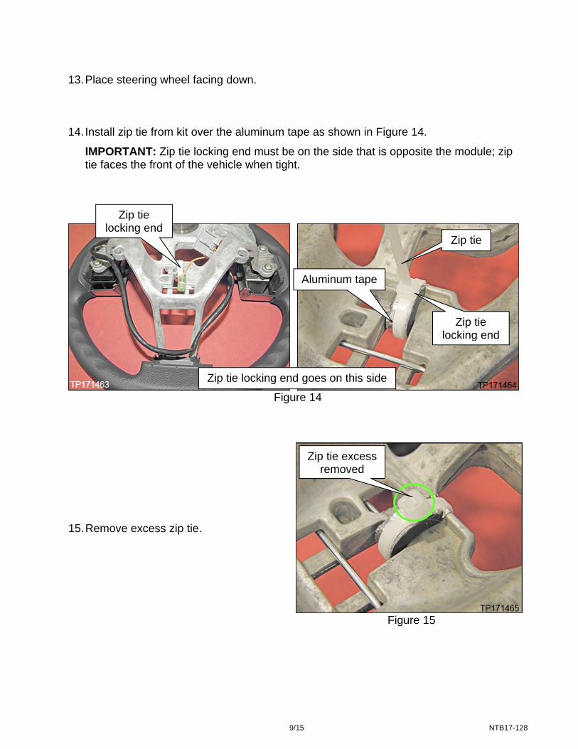
13. Place steering wheel facing down. 14. Install zip tie from kit over the aluminum tape as shown in Figure 14.
IMPORTANT: Zip tie locking end must be on the side that is opposite the module; zip tie faces the front of the vehicle when tight.
Figure 14
Figure 15
15. Remove excess zip tie.
Zip tie
Aluminum tape
Zip tie excess removed
Zip tie locking end goes on this side
Zip tie locking end
Zip tie locking end

10/15 NTB17-128
16. Remove the rib shown in Figure 16 and Figure 17 of the steering wheel finisher with an
appropriate tool.
Trim rib flush with edge of steering wheel finisher.
Figure 16
Figure 17
Rib
Rib before removal
Rib removed
Before After
Edge of steering wheel finisher
Trim here

11/15 NTB17-128
Figure 18
Figure 19
17. Route the steering wheel switch harness
as shown in Figure 18.
NOTE: Harness must be routed between the steering wheel and steering wheel finisher.
18. Re-install the steering wheel finisher to
the steering wheel.
Steering wheel switch harness
Steering wheel finisher

12/15 NTB17-128
INSTALL NEW DRIVER AIR BAG INFLATOR INTO MODULE
Figure 20
Figure 21
Figure 22
19. Remove the four (4) driver air bag
inflator (inflator) nuts shown in Figure 20.
NOTE: These nuts will be replaced later in this procedure.
20. Remove the inflator from the module. 21. Install the new inflator from the Parts
Information into the module as shown in Figure 22.
IMPORTANT: The bar code on the new inflator will be located on the left.
Driver air bag inflator (inflator)
Inflator bar code on left side

13/15 NTB17-128
Figure 23
24. Re-install the steering wheel onto the vehicle in the reverse order of disassembly.
Torque steering wheel nut to 34.3 N•m (3.5 kg-m, 25 ft-lb).
Refer to the ESM, section PS – Power Steering System, for installation information. 25. Install module with new inflator onto the steering wheel in the reverse order of
disassembly.
Refer to the ESM, section PS – Power Steering System, for installation information. 26. Connect both battery cables – positive cable first. 27. Reset the clock and the radio settings. 28. Turn the ignition ON and observe the air bag warning light:
Light should illuminate for 7 seconds and then go out.
NOTE: If the Air Bag Warning light does not operate as described above there may be an issue not covered by this campaign. Refer to ASIST and the appropriate Service Manual for additional diagnostic and repair information.
29. Return the removed (old / non-deployed) inflator in the box that the new inflator
came in.
Follow the return instructions provided by Takata.
Return instructions provided by Takata are attached to this bulletin on page 15.
22. Install four (4) new nuts from the Parts
Information and torque.
Torque the nuts to 5.0 N•m (0.51 kg-m, 44.25 in-lb)
23. Remove the stickers that are covering
the inflator connectors.
NOTE: Figure 23 shows stickers removed.

14/15 NTB17-128
PARTS INFORMATION
DESCRIPTION PART NUMBER QUANTITY MODULE ASSY-AIR BAG, ASSIST
(Driver’s Air Bag Inflator kit) 98560-EM39D 1
Included in kit
INFLATOR 1
NUT 4
RUBBER TAPE 1
ALUMINIUM TAPE 1
CABLE TIE 1
CLAIMS INFORMATION VERSA SEDAN Submit a “CM” line claim using the following claims coding:
CAMPAIGN (“CM”) ID DESCRIPTION OP CODE FRT
PM685 Remove and Replace
Driver’s Air Bag Inflator PM6850 0.6 hrs.
VERSA HATCHBACK Submit a “CM” line claim using the following claims coding:
CAMPAIGN (“CM”) ID DESCRIPTION OP CODE FRT
PM685 Remove and Replace
Driver’s Air Bag Inflator PM6851 0.4 hrs.

15/15 NTB17-128