Embed Size (px)
Citation preview

Volume V:AquaRise
®
Potable WaterPiping Systems
M E C H A N I C A L S Y S T E M S
We build tough products for tough environments®
Mechanical TechnicalManual Series
AquaRise®
Potable Water Piping Systems
Mechanical Technical Manual Series, Vol. V
© 2017 by IPEX Inc. All rights reserved.No part of this book may be used or reproduced in any manner whatsoeverwithout prior written permission. For information contact: IPEX Inc., Marketing,1425 North Service Rd. E., Unit 3, Oakville, Ontario, Canada, L6H 1A7.
IPEX Inc. hereinafter referred to as “IPEX”.
LITERATURE & WEBSITE DISCLAIMER
The information contained here within is based on current information and product designat the time of publication and is subject to change without notification. IPEX does notguarantee or warranty the accuracy, suitability for particular applications, or results to beobtained therefrom.
ABOUT IPEX INC. At IPEX, we have been manufacturing nonmetallic pipe and fittings since 1951. Our products are made availablefor customers thanks to a network of regional stocking locations throughout North America. We offer a widevariety of systems including complete lines of piping, fittings, valves and custom-fabricated items.
More importantly, we are committed to meeting our customers’ needs. As a leader in the plastic piping industry, IPEX continually develops new products, modernizes manufacturing facilities and acquiresinnovative process technology. In addition, our staff take pride in their work, making available to customers theirextensive thermoplastic knowledge and field experience. IPEX personnel are committed to improving the safety,reliability and performance of thermoplastic materials. We are involved in several standards committees and aremembers of and/or comply with the organizations listed on this page.
ii
If you need additional copies of any instructions, or if you have questions about the safe and proper installation of IPEX products, contact IPEX Toll Free 1-866-473-9462.
For the most up-to-date information on IPEX products, visit: ipexna.com
Always adhere to local jobsite and workplace safety regulations.
IPEX AquaRise® Potable Water Piping Systems
WARNING: Do not use or test AquaRise® with compressed air or other gases. Do not use air-over-water boosters.

WARNING: Do not use or test AquaRise® with compressed air or other gases. Do not use air-over-water boosters.
UNDERSTANDING SAFETY ALERT MESSAGES
It is important to read and understand this manual. It contains information to help maintain safety and prevent problems.Improper installation or use of AquaRise® can result in personal injury and/or property damage. It is important to be aware of and recognize safety alert messages as they appear in this manual.
The types of safety alert messages are described below.
This is the safety alert symbol. It is used toalert you to potential personal injury hazards.Obey all safety messages that follow thissymbol to avoid personal injury or death.
The use of the word “NOTE” signifies special instructions which are important but are not related to hazards.
“WARNING” Indicates a hazardous situation which, if not avoided, could result in severe injury or death.
iii
“CAUTION” Indicates a hazardous situation which, if not avoided, could result in minor or moderate injury.
“NOTICE” Indicates a hazardous situation which, if notavoided, may result in system failure and property damage.
IPEX AquaRise® Potable Water Piping Systems
CAUTION
NOTICE
WARNING

AQUARISE SAFETY ALERTS
ivWARNING: Do not use or test AquaRise® with compressed air or other gases. Do not use air-over-water boosters.
Follow all preparation and installation procedures.
AquaRise may only be used in hot and cold potable water distribution systems.
MAINTENANCE, AGING AND REPAIRSALWAYS refer to SECTION 4 of this Technical Manual beforecommencing any maintenance or repairs on any AquaRise
products. Failure to follow instructions may cause cracks orfractures to develop in AquaRise products resulting in
property damage and personal injury.
IPEX AquaRise® Potable Water Piping Systems
WARNING
WARNING
NOTICE
NOTICE
NOTICE
AGING OF TEMPRITE TECHNOLOGYTempRite®* Technology aging can result in changes to
physical characteristics such as increased brittleness andthe reduction in impact resistance. This is precipitated byprolonged elevated operating temperatures or prolonged
exposure to UV light. Refer to SECTION 4 of this TechnicalManual for further details.
* TempRite® is a registered trademark of Lubrizol Advanced Materials, Inc.
• NEVER use compressed air or gas in AquaRise pipe, fittings, and valves
• NEVER use or test AquaRise with compressed air or other gases. Do not use air-over-water boosters.
Use of compressed air or gas in AquaRise pipe,fittings, and valves can result in explosive failuresand cause severe injury or death.
®
SUPPLEMENTAL INFORMATION - DO’S AND DON’TS
vWARNING: Do not use or test AquaRise® with compressed air or other gases. Do not use air-over-water boosters.
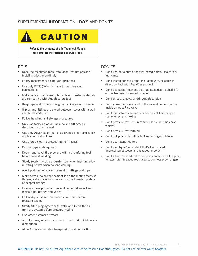
Refer to the contents of this Technical Manual for complete instructions and guidelines.
DO’S• Read the manufacturer's installation instructions and
install product accordingly
• Follow recommended safe work practices
• Use only PTFE (Teflon™) tape to seal threaded connections
• Make certain that gasket lubricants or fire-stop materials are compatible with AquaRise product
• Keep pipe and fittings in original packaging until needed
• If pipe and fittings are stored outdoors, cover with a well-ventilated white tarp
• Follow handling and storage procedures
• Only use tools, on AquaRise pipe and fittings, as described in this manual
• Use only AquaRise primer and solvent cement and follow application instructions
• Use a drop cloth to protect interior finishes
• Cut the pipe ends squarely
• Deburr and bevel the pipe end with a chamfering tool before solvent welding
• Slowly rotate the pipe a quarter turn when inserting pipe in fitting socket when solvent welding
• Avoid puddling of solvent cement in fittings and pipe
• Make certain no solvent cement is on the mating faces of flanges, valves or unions, as well as the threaded portion of adapter fittings
• Ensure excess primer and solvent cement does not run inside pipe, fittings and valves
• Follow AquaRise recommended cure times before pressure testing
• Slowly fill piping system with water and bleed the air from the system before pressure testing
• Use water hammer arrestors
• AquaRise may only be used for hot and cold potable waterdistribution
• Allow for movement due to expansion and contraction
DON'TS• Don't use petroleum or solvent-based paints, sealants or
lubricants
• Don't install adhesive tape, insulated wire, or cable in direct contact with AquaRise product
• Don't use solvent cement that has exceeded its shelf life or has become discolored or jelled
• Don't thread, groove, or drill AquaRise pipe
• Don’t allow the primer and or the solvent cement to run inside an AquaRise valve
• Don't use solvent cement near sources of heat or open flame, or when smoking
• Don't pressure test until recommended cure times have elapsed
• Don't pressure test with air
• Don't cut pipe with dull or broken cutting-tool blades
• Don't use ratchet cutters
• Don't use AquaRise product that's been stored unprotected outdoors and is faded in color
• Don't allow threaded rod to come in contact with the pipe,for example, threaded rods used to connect pipe hangers
IPEX AquaRise® Potable Water Piping Systems
CAUTION
NOTIFICATION TO JOBSITE BUILDING TRADES
vi IPEX AquaRise® Potable Water Piping Systems
WARNING: Do not use or test AquaRise® with compressed air or other gases. Do not use air-over-water boosters.
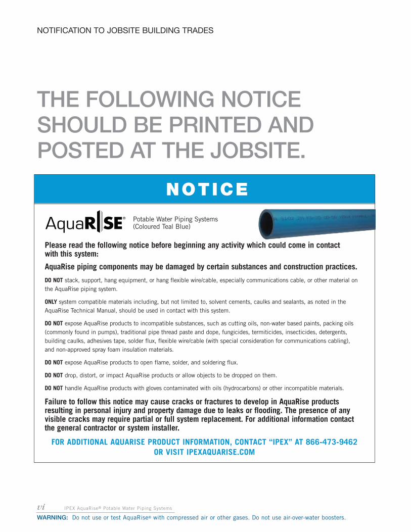
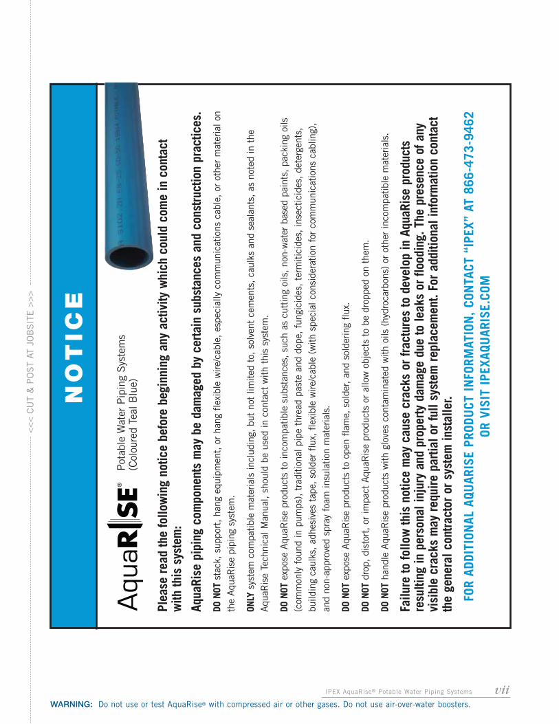
Please read the following notice before beginning any activity which could come in contact with this system:
AquaRise piping components may be damaged by certain substances and construction practices.
DO NOT stack, support, hang equipment, or hang flexible wire/cable, especially communications cable, or other material on the AquaRise piping system.
ONLY system compatible materials including, but not limited to, solvent cements, caulks and sealants, as noted in theAquaRise Technical Manual, should be used in contact with this system.
DO NOT expose AquaRise products to incompatible substances, such as cutting oils, non-water based paints, packing oils(commonly found in pumps), traditional pipe thread paste and dope, fungicides, termiticides, insecticides, detergents,building caulks, adhesives tape, solder flux, flexible wire/cable (with special consideration for communications cabling), and non-approved spray foam insulation materials.
DO NOT expose AquaRise products to open flame, solder, and soldering flux.
DO NOT drop, distort, or impact AquaRise products or allow objects to be dropped on them.
DO NOT handle AquaRise products with gloves contaminated with oils (hydrocarbons) or other incompatible materials.
Failure to follow this notice may cause cracks or fractures to develop in AquaRise products resulting in personal injury and property damage due to leaks or flooding. The presence of anyvisible cracks may require partial or full system replacement. For additional information contact the general contractor or system installer.
FOR ADDITIONAL AQUARISE PRODUCT INFORMATION, CONTACT “IPEX” AT 866-473-9462 OR VISIT IPEXAQUARISE.COM
THE FOLLOWING NOTICESHOULD BE PRINTED ANDPOSTED AT THE JOBSITE.
Potable Water Piping Systems(Coloured Teal Blue)
NOTICE
viiIPEX AquaRise® Potable Water Piping Systems
WARNING: Do not use or test AquaRise® with compressed air or other gases. Do not use air-over-water boosters.
<<< C
UT
& P
OS
T AT
JO
BS
ITE
>>>
Plea
se r
ead
the
follo
win
g no
tice
befo
re b
egin
ning
any
act
ivity
whi
ch c
ould
com
e in
con
tact
w
ith th
is s
yste
m:
Aqua
Rise
pip
ing
com
pone
nts
may
be
dam
aged
by
certa
in s
ubst
ance
s an
d co
nstru
ctio
n pr
actic
es.
DO N
OTst
ack,
sup
port
, ha
ng e
quip
men
t, o
r ha
ng f
lexi
ble
wire
/cab
le, es
peci
ally
com
mun
icat
ions
cab
le, or
oth
er m
ater
ial o
n th
e Aqu
aRis
e pi
ping
sys
tem
.
ONLY
syst
em c
ompa
tible
mat
eria
ls in
clud
ing,
but
not
lim
ited
to, so
lven
t ce
men
ts, ca
ulks
and
sea
lant
s, a
s no
ted
in t
heAqu
aRis
e Te
chni
cal M
anua
l, sh
ould
be
used
in c
onta
ct w
ith t
his
syst
em.
DO N
OTex
pose
Aqu
aRis
e pr
oduc
ts t
o in
com
patib
le s
ubst
ance
s, s
uch
as c
uttin
g oi
ls, no
n-w
ater
bas
ed p
aint
s, p
acki
ng o
ils(c
omm
only
fou
nd in
pum
ps), t
radi
tiona
l pip
e th
read
pas
te a
nd d
ope,
fun
gici
des,
ter
miti
cide
s, in
sect
icid
es, de
terg
ents
,bu
ildin
g ca
ulks
, ad
hesi
ves
tape
, so
lder
flu
x, f
lexi
ble
wire
/cab
le (
with
spe
cial
con
side
ratio
n fo
r co
mm
unic
atio
ns c
ablin
g),
and
non-
appr
oved
spr
ay f
oam
insu
latio
n m
ater
ials
.
DO N
OTex
pose
Aqu
aRis
e pr
oduc
ts t
o op
en f
lam
e, s
olde
r, an
d so
lder
ing
flux.
DO N
OTdr
op, di
stor
t, o
r im
pact
Aqu
aRis
e pr
oduc
ts o
r al
low
obj
ects
to
be d
ropp
ed o
n th
em.
DO N
OTha
ndle
Aqu
aRis
e pr
oduc
ts w
ith g
love
s co
ntam
inat
ed w
ith o
ils (
hydr
ocar
bons
) or
oth
er in
com
patib
le m
ater
ials
.
Failu
re to
follo
w th
is n
otic
e m
ay c
ause
cra
cks
or fr
actu
res
to d
evel
op in
Aqu
aRis
e pr
oduc
ts
resu
lting
in p
erso
nal i
njur
y an
d pr
oper
ty d
amag
e du
e to
leak
s or
floo
ding
. The
pre
senc
e of
any
visi
ble
crac
ks m
ay r
equi
re p
artia
l or
full
syst
em r
epla
cem
ent.
For
addi
tiona
l inf
orm
atio
n co
ntac
t th
e ge
nera
l con
tract
or o
r sy
stem
inst
alle
r.
FOR
ADDI
TION
AL A
QUAR
ISE
PROD
UCT
IN
FORM
ATIO
N,
CON
TACT
“IP
EX”
AT 8
66-4
73-9
462
OR V
ISIT
IPE
XAQU
ARIS
E.CO
M
Pot
able
Wat
er P
ipin
g Sys
tem
s(C
olou
red
Teal
Blu
e)
NOTIC
E

viii IPEX AquaRise® Potable Water Piping Systems
WARNING: Do not use or test AquaRise® with compressed air or other gases. Do not use air-over-water boosters.
For your convenience, there are additional jobsite notice copies located within the last pages of this manual.
If additional copies of any instructions are needed, or for any questions concerning the safe and proper installation of IPEX products,
contact IPEX Toll Free (866) 473-9462 For the most up-to-date information on AquaRise products,
visit: ipexaquarise.com
Always adhere to local jobsite and workplace safety regulations.
ixIPEX AquaRise® Potable Water Piping Systems
WARNING: Do not use or test AquaRise® with compressed air or other gases. Do not use air-over-water boosters.
CONTENTS
About IPEX . . . . . . . . . . . . . . . . . . . . . . . . . . . . . . . . . . . . . . . . . . . . . . . . .ii
Understanding Safety Alert Messages . . . . . . . . . . . . . . . . . . . . . . . . . . . . . .iii
AquaRise® Safety Alerts . . . . . . . . . . . . . . . . . . . . . . . . . . . . . . . . . . . . . . . .iv
Supplemental Information – DO’s and DON’Ts . . . . . . . . . . . . . . . . . . . . . . . . .v
Notification to Jobsite Building Trades . . . . . . . . . . . . . . . . . . . . . . . . . . . . . .vi
SECTION 1: GENERAL
Overview . . . . . . . . . . . . . . . . . . . . . . . . . . . . . . . . . . . . . . . . . . . . . . . . . . . 1
Features and Benefits . . . . . . . . . . . . . . . . . . . . . . . . . . . . . . . . . . . . . . . . . 1
Applications . . . . . . . . . . . . . . . . . . . . . . . . . . . . . . . . . . . . . . . . . . . . . . . . 1
SECTION 2: SYSTEM DESIGN
Material Description . . . . . . . . . . . . . . . . . . . . . . . . . . . . . . . . . . . . . . . . . . 3
Pipe . . . . . . . . . . . . . . . . . . . . . . . . . . . . . . . . . . . . . . . . . . . . . . . . . . . 3
Fittings . . . . . . . . . . . . . . . . . . . . . . . . . . . . . . . . . . . . . . . . . . . . . . . . . 3
Valves . . . . . . . . . . . . . . . . . . . . . . . . . . . . . . . . . . . . . . . . . . . . . . . . . . 3
Product Selection Guide . . . . . . . . . . . . . . . . . . . . . . . . . . . . . . . . . . . . . . . 4
System Pressure and Temperature Ratings . . . . . . . . . . . . . . . . . . . . . . . . . . . 7
Pipe and Molded Fittings . . . . . . . . . . . . . . . . . . . . . . . . . . . . . . . . . . . . . 8
Threaded Adapter Fittings . . . . . . . . . . . . . . . . . . . . . . . . . . . . . . . . . . . . .8
True Union Ball Valves . . . . . . . . . . . . . . . . . . . . . . . . . . . . . . . . . . . . . . 8
Union Fittings and Flanges . . . . . . . . . . . . . . . . . . . . . . . . . . . . . . . . . . . 8
Full Pressure (FP) Flange Kits . . . . . . . . . . . . . . . . . . . . . . . . . . . . . . . . . 8
Maintenance Couplings . . . . . . . . . . . . . . . . . . . . . . . . . . . . . . . . . . . . . . 8
Hydraulic Design . . . . . . . . . . . . . . . . . . . . . . . . . . . . . . . . . . . . . . . . . . . . . 9
Sizing AquaRise Pipe . . . . . . . . . . . . . . . . . . . . . . . . . . . . . . . . . . . . . . . 9
Inside Diameter Comparison . . . . . . . . . . . . . . . . . . . . . . . . . . . . . . . . . . 9
Flow Capacity and Friction Loss through Piping . . . . . . . . . . . . . . . . . . . . 10
Design Velocity . . . . . . . . . . . . . . . . . . . . . . . . . . . . . . . . . . . . . . . . . . . 11
Head Loss Characteristics – Fittings and Valves . . . . . . . . . . . . . . . . . . . . 20
Surge Pressure Calculations . . . . . . . . . . . . . . . . . . . . . . . . . . . . . . . . . . 21
Potential Surge Pressure Given Flow Conditions . . . . . . . . . . . . . . . . . 21
Thrust Forces . . . . . . . . . . . . . . . . . . . . . . . . . . . . . . . . . . . . . . . . . . . . 22
Expansion and Contraction Design . . . . . . . . . . . . . . . . . . . . . . . . . . . . . . . 23
Calculating Expansion and Contraction . . . . . . . . . . . . . . . . . . . . . . . . . . 23
Accommodating Expansion and Contraction . . . . . . . . . . . . . . . . . . . . . . 25
Expansion Loops . . . . . . . . . . . . . . . . . . . . . . . . . . . . . . . . . . . . . . . 25
Change of Direction . . . . . . . . . . . . . . . . . . . . . . . . . . . . . . . . . . . . . 26
Offsets . . . . . . . . . . . . . . . . . . . . . . . . . . . . . . . . . . . . . . . . . . . . . . 26
Thermal Conductivity . . . . . . . . . . . . . . . . . . . . . . . . . . . . . . . . . . . . . . . . . 28
Condensation Potential . . . . . . . . . . . . . . . . . . . . . . . . . . . . . . . . . . . . . 28
Chemical Resistance . . . . . . . . . . . . . . . . . . . . . . . . . . . . . . . . . . . . . . . . . 30

x IPEX AquaRise® Potable Water Piping Systems
WARNING: Do not use or test AquaRise® with compressed air or other gases. Do not use air-over-water boosters.
SECTION 3: INSTALLATION
Safe Handling and Storage of Pipe, Fittings & Valves . . . . . . . . . . . . . . . . . . 31
Solvent Welding . . . . . . . . . . . . . . . . . . . . . . . . . . . . . . . . . . . . . . . . . . . . 31
Safe Handling and Storage of Primers & Solvent Cements . . . . . . . . . . . . .31
Solvent Welding Basics (Summary of Practice) . . . . . . . . . . . . . . . . . . . . 31
Solvent Welding Instructions (Material Preparation) . . . . . . . . . . . . . . . . . 33
One-Step Solvent Welding Procedure . . . . . . . . . . . . . . . . . . . . . . . . . . . 34
Two-Step Solvent Welding Procedure . . . . . . . . . . . . . . . . . . . . . . . . . . . 36
Average Joint SET Schedule For AquaRise Solvent Cement . . . . . . . . . . . 38
Average Joint CURE Schedule For AquaRise Solvent Cement . . . . . . . . . . 38
Cold Weather Solvent Welding . . . . . . . . . . . . . . . . . . . . . . . . . . . . . . . . 39
Hot Weather Solvent Welding . . . . . . . . . . . . . . . . . . . . . . . . . . . . . . . . . 39
Solvent Welding Ball Valves . . . . . . . . . . . . . . . . . . . . . . . . . . . . . . . . . . 39
Vertical Installations for True Union Ball Valves . . . . . . . . . . . . . . . . . . . .40
Flange Connections . . . . . . . . . . . . . . . . . . . . . . . . . . . . . . . . . . . . . . . . . . 41
Flange Installation Guidelines . . . . . . . . . . . . . . . . . . . . . . . . . . . . . . . . . . . 41
Solvent Welding Flanges . . . . . . . . . . . . . . . . . . . . . . . . . . . . . . . . . . . . .41
Solid and Vanstone Flange Connections . . . . . . . . . . . . . . . . . . . . . . . . . .41
Cross Star Bolt Tightening Sequence . . . . . . . . . . . . . . . . . . . . . . . . . . . .42
Full Pressure (FP) Flange Kit Installation . . . . . . . . . . . . . . . . . . . . . . . . .42
Threaded Adapter Fittings . . . . . . . . . . . . . . . . . . . . . . . . . . . . . . . . . . . . . .44
Pipe Supports and Restraints . . . . . . . . . . . . . . . . . . . . . . . . . . . . . . . . . . . 46
Horizontal Piping . . . . . . . . . . . . . . . . . . . . . . . . . . . . . . . . . . . . . . . . . .46
Vertical Piping (Risers) . . . . . . . . . . . . . . . . . . . . . . . . . . . . . . . . . . . . . 46
Supporting Horizontal Take-Offs . . . . . . . . . . . . . . . . . . . . . . . . . . . . .47
Thermal Expansion of Vertical Piping (Risers) . . . . . . . . . . . . . . . . . . .47
Mid-Story Guides . . . . . . . . . . . . . . . . . . . . . . . . . . . . . . . . . . . . . . . 47
System Acceptance (Hydrostatic Pressure) Test . . . . . . . . . . . . . . . . . . . . . . 48
SECTION 4: SYSTEM MAINTENANCE, AGING AND REPAIRS
General Maintenance . . . . . . . . . . . . . . . . . . . . . . . . . . . . . . . . . . . . . . . . . 49
Aging of TempRite® Technology . . . . . . . . . . . . . . . . . . . . . . . . . . . . . . . . . 49
System Repair . . . . . . . . . . . . . . . . . . . . . . . . . . . . . . . . . . . . . . . . . . . . . . 49
Maintenance Couplings . . . . . . . . . . . . . . . . . . . . . . . . . . . . . . . . . . . . . 50
SECTION 5: SPECIFICATIONS . . . . . . . . . . . . . . . . . . . . . . . . . . . . . . . . . . . . . . . . . 55
SECTION 6: AQUARISE®
SPECIFIC TERMS AND CONDITIONS OF SALE AND LIMITED WARRANTY AND LIMITATION OF LIABILITY . . . . . . . . 56
APPENDIX: Notification to Jobsite Building Trades . . . . . . . . . . . . . . . . . . . . . . . . . . . . 58

FEATURES AND BENEFITSCOMPLETE LINE – a matched system of pipe, fittings,valves and solvent cements all offered from a single source.
FULLY CERTIFIED – AquaRise pipe, fittings and solventcements are certified to CSA B137.6 and applicable ASTMstandards. All components are listed to NSF61 for potablewater applications.
WALL THICKNESS - SDR11 thickness provides uniformpressure rating for all sizes.
SIZE RANGE – offered in IPS nominal pipe sizes 1/2"through 4".
COLOUR CODED – with a Teal Blue colour code for pipe,fittings and valves, AquaRise can be easily identified as apotable water piping system within buildings.
LIGHTWEIGHT – when compared to traditional materials,AquaRise is relatively lightweight offering efficiency intransport, handling and installation.
FLOW CAPACITY – AquaRise pipe and fittings have largerinside diameters than most plastic water pipe systems,resulting in increased flow capacity.
CORROSION RESISTANCE – AquaRise CPVC material is resistant to metallic corrosion.
BURNING CHARACTERISTICS – AquaRise pipe and fittingsare listed to ULC S102.2 with Flame Spread and SmokeDeveloped Values of not greater than 25 and 50, respectively.This makes AquaRise acceptable for use in High Buildingsand Plenums in Canada. Always check with local authoritiesfor approval.
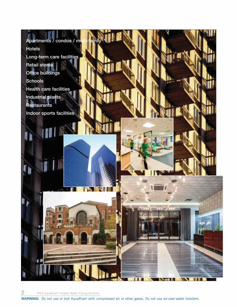
APPLICATIONSAquaRise may only be used in hot and cold potable waterdistribution systems. It may not be used for any otherpiping applications. Using AquaRise for any applicationother than hot and cold potable water distributionsystems will void the AquaRise Limited Warranty.
Common types of buildings where AquaRise may be usedinclude:
Apartments / condos / multi-family•
Hotels•
Long-term care facilities•
Retail stores•
Office buildings•
Schools•
Health care facilities•
Industrial plants•
Restaurants•
Indoor sports facilities•
SECTION 1: GENERAL
AquaRise®* is a thermoplastic piping system designed for the distribution of potable (drinking) water in combustible or non-combustible buildings. Pipe and fittings are manufactured in sizes 1/2" through 4” diameter using a specially formulatedCPVC compound (TempRite® Technology).
This manual provides installers, designers and engineers with guidance to help ensure the proper usage of AquaRise. Readersare encouraged to contact the IPEX Sales Office, or local representative for any further consultation or clarification beforeusing AquaRise to ensure a successful installation.
OVERVIEW
1IPEX AquaRise® Potable Water Piping Systems
GE
NE
RA
L IN
FOR
MATIO
N
WARNING: Do not use or test AquaRise® with compressed air or other gases. Do not use air-over-water boosters.
AquaRise® and the colour of the AquaRise® pipes and fittings are registered trademarks. Distributed in Canada by IPEX Inc., Mississauga, Ontario.
2 IPEX AquaRise® Potable Water Piping Systems
WARNING: Do not use or test AquaRise® with compressed air or other gases. Do not use air-over-water boosters.
Apartments / condos / multi-family
Hotels
Long-term care facilities
Retail stores
Office buildings
Schools
Health care facilities
Industrial plants
Restaurants
Indoor sports facilities

3IPEX AquaRise® Potable Water Piping Systems
SY
STE
M D
ES
IGN
WARNING: Do not use or test AquaRise® with compressed air or other gases. Do not use air-over-water boosters.
SECTION 2: SYSTEM DESIGN
AquaRise pipe, fittings and valves are manufactured from TempRite® Technology (CPVC), which is Teal Blue incolour. The use of any non-AquaRise CPVC components within an AquaRise system is generally prohibited andmust be evaluated and approved by IPEX in writing prior to installation.
MATERIAL DESCRIPTION
PIPE
AquaRise pipe is manufactured to Iron Pipe Size OutsideDiameter (IPS OD) Standard Dimension Ratio (SDR)11dimensions. Pipe is made in 10 ft. lengths and is available in nominal sizes 1/2" – 4". All sizes have the same pressurerating while providing larger inside diameters than mostpotable water systems.
Below are physical dimensions and weights of all AquaRisepipe:
FITTINGS
The AquaRise system offers a wide variety of fittingsincluding Tees, Reducer Tees, Elbows, Couplings, ReducerBushings, and Flanges. All AquaRise fittings aremanufactured to SDR11 thickness and to strict IPEXtolerances to ensure a proper interference fit between pipeand fittings.
Speciality fittings are also available including MaintenanceCouplings, Repair Assemblies and Full-Pressure Flange Kits.
VALVES
AquaRise True Union Ball Valves are available in sizes 1/2"through 2". True union connections allow for easy valveremoval and replacementwithout having to cut thepipe. This valve usesspecially selected O-ringseals for performance inpotable water where a varietyof treatment chemicals maybe used.
In sizes above 2", users mayalso choose to select from arange of IPEX IndustrialValves such as the VXE CPVCBall Valve or FK CPVC Butterfly Valve.
NomSize (in.)
Avg. OD (in.)
Avg. ID
(in.)
Avg. WallThickness
(in.)
Wt Pipe -Empty(lb/ft)
Wt Pipe - Full of Water
(lb/ft)
1/2 0.840 0.679 0.081 0.13 0.76
3/4 1.050 0.847 0.101 0.20 1.18
1 1.315 1.061 0.127 0.32 1.85
1-1/4 1.660 1.340 0.160 0.51 2.95
1-1/2 1.900 1.534 0.183 0.66 3.86
2 2.375 1.917 0.229 1.04 6.04
2-1/2 2.875 2.321 0.277 1.52 8.29
3 3.500 2.826 0.337 2.25 13.12
4 4.500 3.633 0.434 3.87 21.83
A. Imperial Units
NomSize (in.)
Avg. OD
(mm)
Avg. ID
(mm)
Avg. WallThickness
(mm)
Wt Pipe -Empty(kg/m)
Wt Pipe - Full of Water
(kg/m)
1/2 21.3 17.2 2.06 0.19 1.13
3/4 26.7 21.5 2.57 0.30 1.76
1 33.4 26.9 3.23 0.48 2.76
1-1/4 42.2 34.0 4.06 0.76 4.40
1-1/2 48.3 39.0 4.65 0.99 5.76
2 60.3 48.7 5.82 1.55 9.00
2-1/2 73.0 56.7 7.04 2.27 12.36
3 88.9 71.8 8.56 3.36 19.56
4 114.3 92.3 11.02 5.77 32.55
B. SI Units
SY
STE
M D
ES
IGN
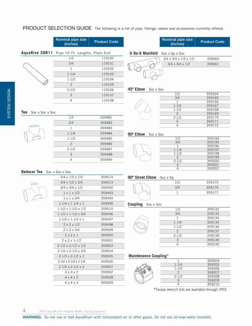
PRODUCT SELECTION GUIDE The following is a list of pipe, fittings, valves and accessories currently offered.
4 IPEX AquaRise® Potable Water Piping Systems
WARNING: Do not use or test AquaRise® with compressed air or other gases. Do not use air-over-water boosters.
1/2 119100
3/4 119101
1 119102
1-1/4 119103
1-1/2 119104
2 119105
2-1/2 119106
3 119107
4 119108
AquaRise SDR11 Pipe 10 Ft. Lengths, Plain End
1/2 359481
3/4 359482
1 359483
1-1/4 359484
1-1/2 359485
2 359486
2-1/2 359487
3 359488
4 359489
Tee Soc x Soc x Soc
Reducer Tee Soc x Soc x Soc3/4 x 1/2 x 1/2 359514
3/4 x 1/2 x 3/4 359513
3/4 x 3/4 x 1/2 359492
1 x 1 x 1/2 359493
1 x 1 x 3/4 359494
1-1/4 x 1-1/4 x 1 359495
1-1/2 x 1-1/2 x 1/2 359515
1-1/2 x 1-1/2 x 3/4 359496
1-1/2 x 1-1/2 x 1 359497
2 x 2 x 1/2 359498
2 x 2 x 3/4 359499
2 x 2 x 1 359500
2 x 2 x 1-1/2 359501
2-1/2 x 2-1/2 x 1/2 359503
2-1/2 x 2-1/2 x 3/4 359504
2-1/2 x 2-1/2 x 1 359505
2-1/2 x 2-1/2 x 1-1/4 359506
2-1/2 x 2-1/2 x 2 359507
3 x 3 x 2 359502
4 x 4 x 2 359508
4 x 4 x 3 359509
1/2 3591943/4 3591951 359196
1-1/4 3591971-1/2 359198
2 3591992-1/2 359200
3 3592014 359202
90º Elbow Soc x Soc
1/2 3591323/4 3591331 359134
1-1/4 3591351-1/2 359136
2 3591372-1/2 359138
3 3591394 359140
45º Elbow Soc x Soc1/2 3591643/4 3591651 359166
1-1/4 3591671-1/2 359168
2 3591692-1/2 359170
3 3591714 359172
1/2 359175
3/4 359176
1 359177
90º Street Elbow Soc x Sp
1 3592041-1/4 3592051-1/2 359206
2 3592072-1/2 359208
3 3592094 359210
Maintenance Coupling*
*Torque wrench kits are available through IPEX
Nominal pipe size(Inches)
Product CodeNominal pipe size
(Inches)Product Code
3/4 x 3/4 x 1/2 x 1/2 359060
3/4 x 3/4 x 1/2 359061
U Do-It Manifold Soc x Sp x Soc
Coupling Soc x Soc

5IPEX AquaRise® Potable Water Piping Systems
SY
STE
M D
ES
IGN
WARNING: Do not use or test AquaRise® with compressed air or other gases. Do not use air-over-water boosters.
Reducer Coupling Soc x Soc3/4 x 1/2 359460
1 x 1/2 359461
1 x 3/4 359462
1-1/4 x 1 359463
1-1/2 x 1 359465
1-1/2 x 1-1/4 359466
2 x 1 359467
2 x 1-1/2 359458
3 x 2 359470
4 x 2 359459
4 x 3 359472
1/2 359109
3/4 359110
1 359111
1-1/4 359112
1-1/2 359113
2 359114
2-1/2 359115
3 359116
4 359107
Cap Soc
1/2 359520
3/4 359521
1 359522
1-1/4 359523
1-1/2 359524
2 359525
3 359051
4 359550
Union Soc x Soc
1/2 3592283/4 3592291 359230
1-1/4 3592311-1/2 359232
2 3592332-1/2 359234
3 3592354 359236
Flange Soc Solid Style
Reducer Bushing Sp x Soc
3/4 x 1/2 359375
1 x 1/2 359376
1 x 3/4 359377
1-1/4 x 1/2 359378
1-1/4 x 3/4 359379
1-1/4 x 1 359380
1-1/2 x 1/2 359381
1-1/2 x 3/4 359382
1-1/2 x 1 359383
1-1/2 x 1-1/4 359384
2 x 1/2 359385
2 x 3/4 359386
2 x 1 359387
2 x 1-1/4 359388
2 x 1-1/2 359389
2-1/2 x 3/4 359390
2-1/2 x 1 359391
2-1/2 x 2 359392
3 x 1-1/2 359393
3 x 2 359394
3 x 2-1/2 359395
4 x 1-1/4 359428
4 x 1-1/2 359429
4 x 2 359396
4 x 2-1/2 359430
4 x 3 359397
Nominal pipe size(Inches)
Product CodeNominal pipe size
(Inches)Product Code
2-1/2 359057
3 359058
4 359059
Repair Flange Solid Style Flange x Pipe Stub
2-1/2 3590403 3590414 359043
Full Pressure (FP) Flange Kit
Vanstone Flange Soc4 359270
Note: Kit includes one (1) AquaRisesocket flange - solid style, gasket and allrequired hardware.
1 - 4 359212
Torque Wrench Kit (for use on Maintenance Cuplings)
Note: Kit includes sockets

SY
STE
M D
ES
IGN
6 IPEX AquaRise® Potable Water Piping Systems
WARNING: Do not use or test AquaRise® with compressed air or other gases. Do not use air-over-water boosters.
PRODUCT SELECTION GUIDE
Nominal pipe size(Inches)
Product Code
Aquarise One-Step Cement**Pint 473 ml 359086
Quart 946 ml 359092
Gallon 3785 ml 359091
Aquarise Two-Step Cement w/Primer***
Can-Mate Daubers (with telescoping shaft)CM-75 (pipe sizes 1/2" - 1-1/4") 074436
CM-150 (pipe sizes 1-1/2" - 3") 074437
DP 50 (pipe sizes 1/2" - 1") 074455
DP 150 (pipe sizes 1-1/4" - 3") 074421
DQ 50 (pipe sizes 1/2" - 1") 074193
DQ 150 (pipe sizes 1-1/4" - 3") 074422
Cap Daubers
Note: DP fits Pint cans and DQ fits Quart cans
4" 359551
AquaRise Superswab ReplacementSwab is disposable andreplaceable
359826
1/2, 3/4, 1 359044
1-1/4 to 4 359062
Beveling Tools
**For use on 1/2" to 2"
***For use on 2-1/2", 3" & 4"
Nominal pipe size (Inches)Product
Code
SwabTrue Union Ball Valve Soc x Soc1/2 359000
3/4 359001
1 359002
1-1/4 359003
1-1/2 359004
2 359005
Rated to 232 psi @ 73°FRated to 72 psi @ 160°F
Cement products come complete with Primeras required and extra daubers.
Quart 946 ml 359087
Gallon 3785 ml 359093
Description ProductCodeimperial metric
Male Threaded Adapter Soc x Bronze MNPT1/2 359811
3/4 359812
1 359813
1-1/4 359814
1-1/2 359815
2 359816
1/2 359820
3/4 359821
1 359822
Female Threaded Adapter Sp x Bronze FNPT
1 359063
1-1/4 359064
1-1/2 359077
2 359065
Repair Threaded Adapter Sp x Bronze FNPT
1/2 359823
3/4 359824
1 359825
Male Threaded Adapter Sp x Bronze MNPT
Female Threaded Adapter Soc x Bronze FNPT1/2 359800
3/4 359801
1 359802
1-1/4 359803
1-1/2 359804
2 359805

Maximum Operating Pressure vs. Temperature
Operating Temperature, ºF (ºC)
40 (5)0
50
100
150
200
250
300
350
400
73 (23) 80 (27) 90 (32) 100 (38) 110 (43) 120 (49) 130 (55) 140 (60) 150 (66) 160 (71)
Max
imum
Ope
ratin
g Pr
essu
re, P
si
Pipe, Molded Fittings, Threaded Adapters, Full Pressure Flange Kits and Maintenance Couplings
True Union Ball Valves
Union Fittings, Flanges, Vanstone Flanges
7IPEX AquaRise® Potable Water Piping Systems
SY
STE
M D
ES
IGN
WARNING: Do not use or test AquaRise® with compressed air or other gases. Do not use air-over-water boosters.
The following graph provides a quick reference for maximum operating pressure of pipe, valvesand fittings at various temperatures in hot and cold potable water distribution systems.
Maximum operating temperature of AquaRise systems must not exceed 160˚F (71˚C).
Maximum operating temperatures and pressures of thelowest rated component in the piping system must not be
exceeded during pressure testing or system operation.Always design to limit and accommodate all surge
pressures in an AquaRise system.
SYSTEM PRESSURE AND TEMPERATURE RATINGS
Maximum operating temperatures and pressures of the lowest rated component in the piping system must not beexceeded during pressure testing or system operation. Always design to limit and accommodate all surge pressures inan AquaRise system.
NOTICE NOTICE

8 IPEX AquaRise® Potable Water Piping Systems
WARNING: Do not use or test AquaRise® with compressed air or other gases. Do not use air-over-water boosters.
SY
ST
EM
DE
SIG
N
PIPE AND MOLDED FITTINGS
All AquaRise pipe, One-piece ball valves and the followingmolded fittings (couplings, tees, elbows, bushings and caps)have a pressure rating of 400 psi at 73ºF (2,758 kPa at23ºC) and 150 psi at 160ºF (1,034 kPa at 71ºC).
THREADED ADAPTER FITTINGS
AquaRise Threaded Adapter Fittings provide a transition fromAquaRise to metallicthreaded accessories such asvalves, pumps or alternativematerials. The adapterfittings have the samepressure ratings as AquaRisepipe – and are rated at 400psi at 73ºF (2,758 kPa at23ºC) and 150 psi at 160ºF(1,034 kPa at 71ºC).
TRUE UNION BALL VALVES
AquaRise true union ball valveshave a pressure rating of 232 psiat 73ºF (1,600 kPa at 23ºC) and72 psi at 160ºF (496 kPa at 71ºC).
UNION FITTINGS ANDFLANGES
Due to the presence ofmechanical seals, AquaRiseunions and flanges have a coldwater pressure rating of 150 psiat 73ºF (1,034 kPa at 23ºC).This rating is reduced at highertemperatures with a limit of 57psi at 160ºF (393 kPa at 71ºC).
FULL PRESSURE (FP) FLANGE KITS
IPEX FP Flange Kits are specifically designed to increase thepressure capability of an AquaRise one-piece flange. TheAquaRise Full Pressure Flange Kits have a pressure ratingequal to that of AquaRise pipe in each of the 3 sizes offered(2-1/2", 3" and 4"). The pressure rating is valid forconnections to solid flat face metal flanges or to a secondAquaRise FP Flange Kit. The Full Pressure Flange Kits have amaximum pressure rating of 400 psi at 73ºF (2,758 kPa at23ºC) and 150 psi at 160ºF (1,034 kPa at 71ºC).
MAINTENANCE COUPLINGS
Maintenance Couplings provide a fast ‘pipe to pipe’alternative connection for AquaRise. They are ideal for quickrepairs of AquaRise pipe in need of maintenance withoutpossible delays due tonecessary cure timesassociated with solventcement.
Available sizes are 1" through4". The couplings carry thesame pressure ratings asAquaRise pipe – and are ratedat 400 psi at 73ºF (2,758 kPaat 23ºC) and 150 psi at 160ºF(1,034 kPa at 71ºC).
In compliance with plumbing code requirements, AquaRise pipe, molded fittings (couplings, tees, elbows,bushings and caps) and threaded adapter fittings are certified to CSA B137.6 and applicable ASTM Standards.Union fittings and flanges are certified to applicable ASTM standards.

WARNING: Do not use or test AquaRise® with compressed air or other gases. Do not use air-over-water boosters.
SY
ST
EM
DE
SIG
N
HYDRAULIC DESIGN
SIZING AQUARISE PIPEProper sizing design is necessary to create a balance betweenflow velocity, flow volume and pressure head losses. Due tosimilar inside diameter dimensions, AquaRise may use designsizes similar to copper. Depending on design velocityconsiderations, AquaRise may even permit designers to useone nominal size smaller than copper.
INSIDE DIAMETER COMPARISON
An AquaRise water distribution system offers increased flowcapacity when compared to alternative piping materials.AquaRise and Type L copper have similar inside diameterswhile PEX and CTS CPVC are considerably smaller. Most ofthe time, during pipe sizing of a water distribution system,AquaRise can be used as a direct substitute for Type Lcopper for new designs and system replacements while onenominal size larger of PEX or CTS CPVC may be required tomaintain equivalent flow and velocity.
In addition, it is also important to remember that thecomparative volume flow capacities are proportional to thesquare of the inside diameters. For example, 1" AquaRise hasa 23% larger inside diameter than 1" PEX. This results in a52% larger flow area than PEX.
Nom. Pipe Size
(in)
AquaRise(in)
Copper Type L
(in)
PEX SDR 9
(in)
CTS CPVC
(in)
1/2 0.679 0.545 0.475 0.479
3/4 0.847 0.785 0.670 0.695
1 1.061 1.025 0.861 0.903
1-1/4 1.340 1.265 1.054 1.104
1-1/2 1.534 1.505 1.245 1.310
2 1.917 1.985 1.629 1.717
2-1/2 2.321 2.465
3 2.826 2.945
4 3.633 3.905
Inside Diameter Comparison
IPEX AquaRise® Potable Water Piping Systems 9

SY
STE
M D
ES
IGN
10 IPEX AquaRise® Potable Water Piping Systems
FLOW CAPACITY AND FRICTION LOSS THROUGHPIPING
The flow capacity of a pipe is related to its inside diameter.As fluid flows through a piping system, it will experiencefriction resistance between the fluid and the pipe wallresulting in a pressure loss. This pressure loss is a result offluid density, viscosity, velocity, temperature, type of flow,and smoothness of the pipe wall.
Friction loss for AquaRise pipe can be determined using thefollowing equations.
DARCY-WEISBACH EQUATION
The most widely used equation to calculate friction loss inwater distribution systems is the Darcy-Weisbach equation.This equation takes into account the density of water at agiven temperature, the pipe roughness, the water velocity,and the length of the pipe run.
Where:
HL = Frictional head loss (ft. water) (One ft. of water = 0.4335 psi)
f = friction factor (dimensionless)
L = length of pipe (ft)
di = inside diameter of pipe (ft)
V = flow velocity (ft/s)
g = gravitational acceleration (32.2 ft/s2)
First, designers are reminded of the velocity and flow raterelationship.
Velocity = Volumetric Flow / Pipe Area, or V = Q/A.
To allow the use of the formula with commonly used units ofmeasure, it can be rearranged as follows:
Where:
V = flow velocity (ft/s)
Q = volumetric flow (US gpm)
di = inside diameter of pipe (in)
Next, the dimensionless friction factor (f) must bedetermined. Water distribution systems generally operate inthe turbulent flow regime. Therefore, the friction factor isderived using the Colebrook equation, where f is solvedimplicitly.
Where:
f = friction factor (dimensionless)
E = absolute pipe roughness (5 x 10⁻⁶ ft for AquaRise pipe)
di = inside diameter of pipe (ft)
Re = Reynolds number (Re = pVD/µ)
Where:
p = density of water (lbm/ft3)
V = flow velocity (ft/s)
di = inside diameter of pipe (ft)
µ = dynamic viscosity (lbm/ft•s)
For turbulent flow, the Reynolds number is greater than > 4000.
The friction factor (f) can also be determined using astandard Moody chart. The Moody chart shows therelationship between the friction factor, the Reynoldsnumber, and the relative pipe roughness (the ratio betweenthe absolute pipe roughness (ε) and inside diameter of thepipe (di), ε ⁄ (di))
Once the friction factor has been determined, it can then beused in the Darcy-Weisbach equation to calculate thefrictional head loss.
The friction loss tables on the pages that follow use theDarcy-Weisbach equation to determine head loss forAquaRise pipe. At ipexaquarise.com, there is a convenientAquaRise® Pipe Flow Capacity and Friction Loss Calculator.
Contact IPEX for further assistance.
WARNING: Do not use or test AquaRise® with compressed air or other gases. Do not use air-over-water boosters.
V =(0.4085)Q
di2
1+2.51

11IPEX AquaRise® Potable Water Piping Systems
HAZEN-WILLIAMS EQUATION
A commonly used equation to calculate friction loss in waterdistribution systems is the Hazen-Williams equation. Thisequation is generally valid for water flowing in pipe sizeslarger than 2" and temperatures between 40°F and 75°F.Using this equation, designers can calculate the frictionlosses, also known as Head Loss (HL) for a given pipe sizeand the flow rate, Q.
First, designers are reminded of the velocity and flow raterelationship.
Velocity = Volumetric Flow / Pipe Area, or V = Q/A.
To allow the use of the formula with commonly used units ofmeasure, it can be rearranged as follows:
Where:
V = flow velocity (ft/s)
Q = volumetric flow (US gpm)
di = inside diameter of pipe (in.)
The Hazen-Williams empirical formula for calculating headloss is as follows,
Where:
HL = Frictional head loss (ft. water/100ft)(One foot of water = 0.4335 psi)
C = Hazen-William factor (150 for AquaRise)
di = Inside diameter of pipe (in)
This formula can be simplified for use with AquaRise bysubstituting C =150 and by converting units for HL toread as,
DESIGN VELOCITY
The maximum design velocity for AquaRise systems is 8 ft/s(2.44 m/s). This limit is considered a good balance betweenmaximizing flow capacity while minimizing frictional headlosses and water hammer potential. This velocity limit doesnot account for possible erosion of metallic systemcomponents and fixtures. The system must be designed andinstalled utilizing good engineering practices.
To minimize water hammer and prevent damage to thesystem, use slow closing valves and water hammerarrestors, regardless of the velocities. S
YS
TEM
DE
SIG
NG
EN
ER
AL
INFO
RM
ATION
WARNING: Do not use or test AquaRise® with compressed air or other gases. Do not use air-over-water boosters.
V =(0.4085)Q
di2
HL =0.2083(100/C1.852(Q)1.852
(di)4.8655
HL =0.0983(Q)1.852
(di)4.8655

40°F (5°C) 60°F (16°C) 80°F (27°C)
FlowRate
VelocityFriction
Head Loss(ft water/100 ft)
FrictionPressure
(psi/100 ft)
FrictionHead Loss
(ft water/100 ft)
FrictionPressure
(psi/100 ft)
FrictionHead Loss
(ft water/100 ft)
FrictionPressure
(psi/100 ft)
gpm US L/sec ft/s 3/4" 3/4" 3/4"
1 0.06 0.57 0.33 0.14 0.30 0.13 0.28 0.122 0.13 1.14 1.08 0.47 0.99 0.43 0.92 0.403 0.19 1.71 2.17 0.94 1.99 0.86 1.86 0.814 0.25 2.28 3.57 1.55 3.29 1.42 3.08 1.335 0.32 2.85 5.27 2.28 4.86 2.11 4.56 1.976 0.38 3.42 7.25 3.14 6.70 2.90 6.29 2.727 0.44 3.99 9.49 4.11 8.79 3.81 8.26 3.588 0.50 4.56 12.00 5.20 11.13 4.82 10.47 4.539 0.57 5.12 14.76 6.39 13.70 5.93 12.90 5.59
10 0.63 5.69 17.78 7.70 16.52 7.15 15.56 6.74
40°F (5°C) 60°F (16°C) 80°F (27°C)
FlowRate
VelocityFriction
Head Loss(ft water/100 ft)
FrictionPressure
(psi/100 ft)
FrictionHead Loss
(ft water/100 ft)
FrictionPressure
(psi/100 ft)
FrictionHead Loss
(ft water/100 ft)
FrictionPressure
(psi/100 ft)
gpm US L/sec ft/s 1" 1" 1"
5 0.32 1.81 1.81 0.78 1.67 0.72 1.56 0.686 0.38 2.18 2.49 1.08 2.29 0.99 2.15 0.937 0.44 2.54 3.25 1.41 3.00 1.30 2.82 1.228 0.50 2.90 4.11 1.78 3.80 1.65 3.57 1.549 0.57 3.27 5.05 2.19 4.67 2.02 4.39 1.90
10 0.63 3.63 6.08 2.63 5.63 2.44 5.29 2.2915 0.95 5.44 12.42 5.38 11.55 5.00 10.90 4.7220 1.26 7.26 20.68 8.95 19.29 8.35 18.23 7.90
12 IPEX AquaRise® Potable Water Piping Systems
WARNING: Do not use or test AquaRise® with compressed air or other gases. Do not use air-over-water boosters.
SY
ST
EM
DE
SIG
N
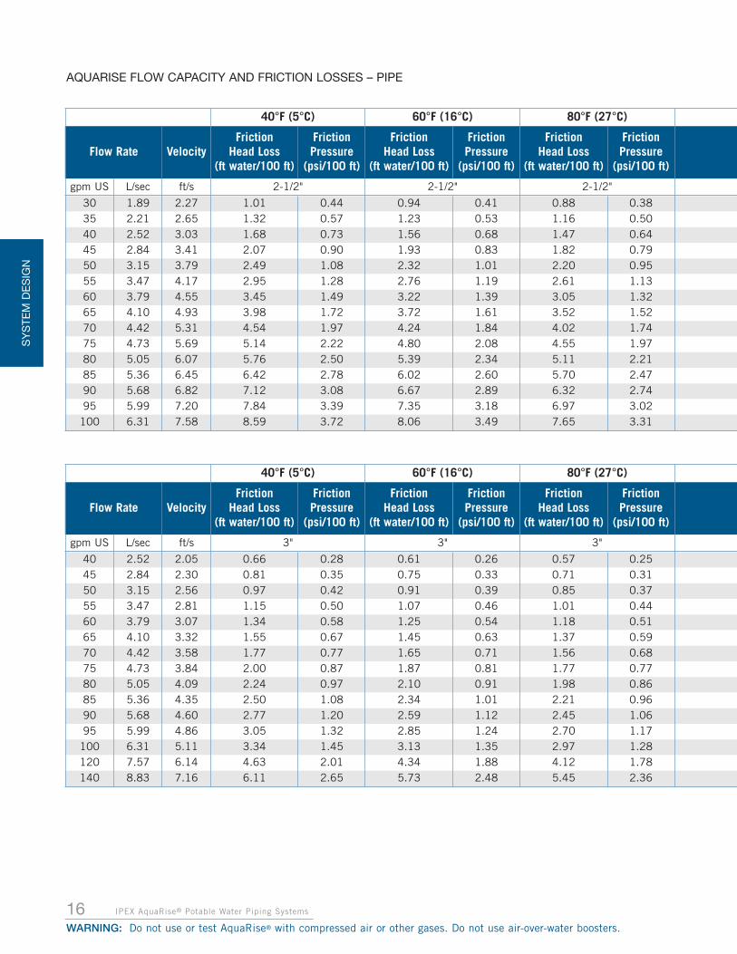
AQUARISE FLOW CAPACITY AND FRICTION LOSSES – PIPE
40°F (5°C) 60°F (16°C) 80°F (27°C)
Flow Rate VelocityFriction
Head Loss(ft water/100 ft)
FrictionPressure
(psi/100 ft)
FrictionHead Loss
(ft water/100 ft)
FrictionPressure
(psi/100 ft)
FrictionHead Loss
(ft water/100 ft)
FrictionPressure
(psi/100 ft)
gpm US L/sec ft/s 1/2" 1/2" 1/2"
1 0.06 0.89 0.94 0.41 0.85 0.37 0.79 0.342 0.13 1.77 3.07 1.33 2.81 1.22 2.62 1.143 0.19 2.66 6.18 2.68 5.69 2.46 5.32 2.314 0.25 3.54 10.20 4.42 9.42 4.08 8.83 3.825 0.32 4.43 15.07 6.52 13.94 6.04 13.10 5.676 0.38 5.32 20.75 8.98 19.23 8.33 18.09 7.837 0.44 6.20 27.21 11.78 25.26 10.94 23.79 10.308 0.50 7.09 34.44 14.91 32.01 13.86 30.18 13.079 0.57 7.97 42.41 18.36 39.46 17.09 37.25 16.13

100°F (38°C) 120°F (49°C) 140°F (60°C) 160°F (71°C)
FrictionHead Loss
(ft water/100 ft)
FrictionPressure
(psi/100 ft)
FrictionHead Loss
(ft water/100 ft)
FrictionPressure
(psi/100 ft)
FrictionHead Loss
(ft water/100 ft)
FrictionPressure
(psi/100 ft)
FrictionHead Loss
(ft water/100 ft)
FrictionPressure
(psi/100 ft)
3/4" 3/4" 3/4" 3/4"
0.26 0.11 0.25 0.11 0.24 0.10 0.23 0.100.87 0.37 0.82 0.36 0.79 0.34 0.76 0.331.76 0.76 1.68 0.73 1.61 0.70 1.55 0.672.92 1.26 2.78 1.21 2.68 1.16 2.59 1.124.32 1.87 4.13 1.79 3.98 1.72 3.85 1.675.97 2.58 5.71 2.47 5.50 2.38 5.33 2.317.85 3.40 7.52 3.26 7.25 3.14 7.02 3.049.96 4.31 9.54 4.13 9.20 3.98 8.92 3.86
12.28 5.32 11.78 5.10 11.37 4.92 11.03 4.7814.83 6.42 14.23 6.16 13.74 5.95 13.34 5.77
100°F (38°C) 120°F (49°C) 140°F (60°C) 160°F (71°C)
FrictionHead Loss
(ft water/100 ft)
FrictionPressure
(psi/100 ft)
FrictionHead Loss
(ft water/100 ft)
FrictionPressure
(psi/100 ft)
FrictionHead Loss
(ft water/100 ft)
FrictionPressure
(psi/100 ft)
FrictionHead Loss
(ft water/100 ft)
FrictionPressure
(psi/100 ft)
1" 1" 1" 1"
1.48 0.64 1.41 0.61 1.35 0.59 1.31 0.572.04 0.88 1.94 0.84 1.87 0.81 1.81 0.782.67 1.16 2.56 1.11 2.46 1.07 2.38 1.033.39 1.47 3.24 1.40 3.12 1.35 3.02 1.314.17 1.81 4.00 1.73 3.85 1.67 3.73 1.625.03 2.18 4.82 2.09 4.65 2.01 4.51 1.95
10.39 4.50 9.98 4.32 9.64 4.17 9.36 4.0517.41 7.54 16.75 7.25 16.21 7.02 15.75 6.82
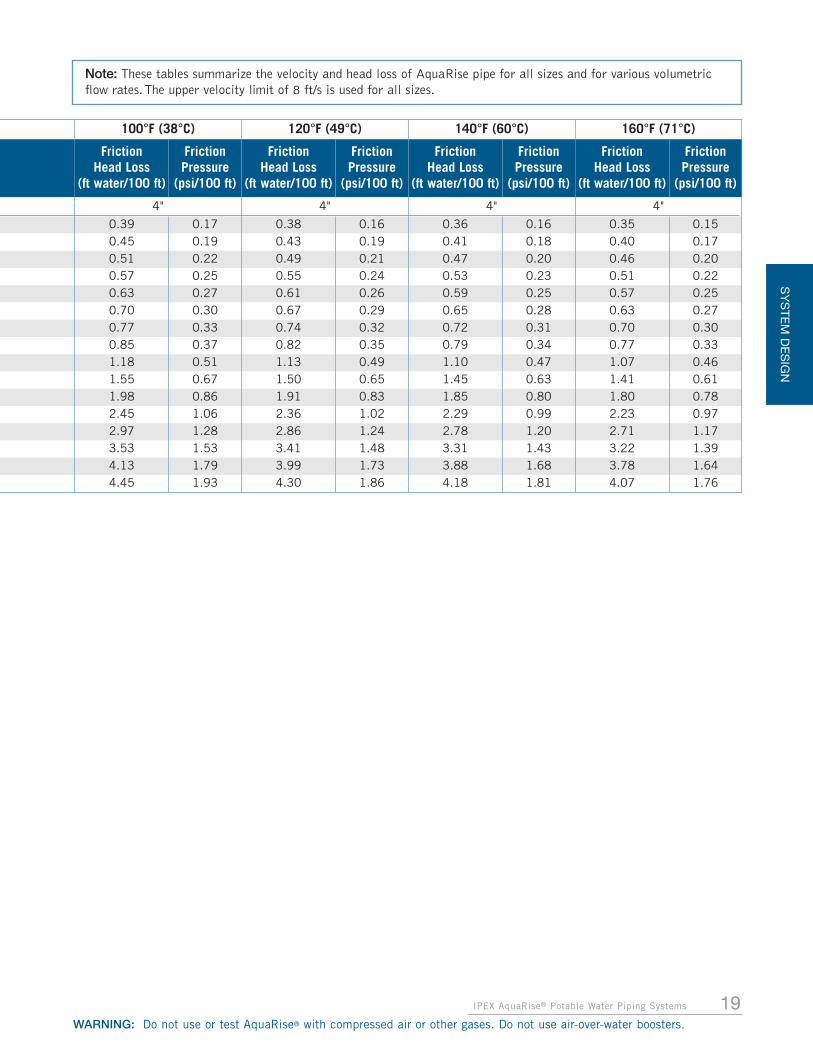
Note: These tables summarize the velocity and head loss of AquaRise pipe for all sizes and for various volumetricflow rates. The upper velocity limit of 8 ft/s is used for all sizes.
WARNING: Do not use or test AquaRise® with compressed air or other gases. Do not use air-over-water boosters.
SY
ST
EM
DE
SIG
N
IPEX AquaRise® Potable Water Piping Systems 13
100°F (38°C) 120°F (49°C) 140°F (60°C) 160°F (71°C)
FrictionHead Loss
(ft water/100 ft)
FrictionPressure
(psi/100 ft)
FrictionHead Loss
(ft water/100 ft)
FrictionPressure
(psi/100 ft)
FrictionHead Loss
(ft water/100 ft)
FrictionPressure
(psi/100 ft)
FrictionHead Loss
(ft water/100 ft)
FrictionPressure
(psi/100 ft)
1/2" 1/2" 1/2" 1/2"
0.74 0.32 0.70 0.30 0.67 0.29 0.65 0.282.47 1.07 2.36 1.02 2.26 0.98 2.18 0.945.04 2.18 4.81 2.08 4.62 2.00 4.47 1.938.37 3.63 8.01 3.47 7.71 3.34 7.46 3.23
12.44 5.39 11.91 5.16 11.48 4.97 11.12 4.8117.21 7.45 16.49 7.14 15.91 6.89 15.42 6.6822.65 9.81 21.74 9.41 20.98 9.09 20.36 8.8228.76 12.45 27.62 11.96 26.68 11.55 25.90 11.2235.53 15.38 34.14 14.78 33.00 14.29 32.06 13.88

SY
STE
M D
ES
IGN
14 IPEX AquaRise® Potable Water Piping Systems
WARNING: Do not use or test AquaRise® with compressed air or other gases. Do not use air-over-water boosters.
AQUARISE FLOW CAPACITY AND FRICTION LOSSES – PIPE
40°F (5°C) 60°F (16°C) 80°F (27°C)
Flow Rate VelocityFriction
Head Loss(ft water/100 ft)
FrictionPressure
(psi/100 ft)
FrictionHead Loss
(ft water/100 ft)
FrictionPressure
(psi/100 ft)
FrictionHead Loss
(ft water/100 ft)
FrictionPressure
(psi/100 ft)
gpm US L/sec ft/s 1-1/4" 1-1/4" 1-1/4"
8 0.50 1.82 1.36 0.59 1.25 0.54 1.17 0.519 0.57 2.05 1.66 0.72 1.54 0.67 1.44 0.62
10 0.63 2.27 2.00 0.87 1.85 0.80 1.74 0.7515 0.95 3.41 4.08 1.77 3.78 1.64 3.56 1.5420 1.26 4.55 6.78 2.93 6.30 2.73 5.95 2.5725 1.58 5.69 10.06 4.36 9.38 4.06 8.86 3.8430 1.89 6.82 13.91 6.03 12.99 5.63 12.29 5.3235 2.21 7.96 18.32 7.93 17.12 7.41 16.22 7.02
40°F (5°C) 60°F (16°C) 80°F (27°C)
Flow Rate VelocityFriction
Head Loss(ft water/100 ft)
FrictionPressure
(psi/100 ft)
FrictionHead Loss
(ft water/100 ft)
FrictionPressure
(psi/100 ft)
FrictionHead Loss
(ft water/100 ft)
FrictionPressure
(psi/100 ft)
gpm US L/sec ft/s 1-1/2" 1-1/2" 1-1/2"
10 0.63 1.74 1.05 0.46 0.97 0.42 0.91 0.3915 0.95 2.60 2.14 0.93 1.98 0.86 1.87 0.8120 1.26 3.47 3.55 1.54 3.30 1.43 3.11 1.3525 1.58 4.34 5.27 2.28 4.91 2.13 4.63 2.0130 1.89 5.21 7.29 3.16 6.79 2.94 6.42 2.7835 2.21 6.08 9.58 4.15 8.95 3.87 8.46 3.6740 2.52 6.94 12.16 5.26 11.36 4.92 10.76 4.6645 2.84 7.81 15.01 6.50 14.04 6.08 13.30 5.76
40°F (5°C) 60°F (16°C) 80°F (27°C)
FlowRate
VelocityFriction
Head Loss(ft water/100 ft)
FrictionPressure
(psi/100 ft)
FrictionHead Loss
(ft water/100 ft)
FrictionPressure
(psi/100 ft)
FrictionHead Loss
(ft water/100 ft)
FrictionPressure
(psi/100 ft)
gpm US L/sec ft/s 2" 2" 2"
20 1.26 2.22 1.23 0.53 1.14 0.49 1.07 0.4625 1.58 2.78 1.82 0.79 1.69 0.73 1.59 0.6930 1.89 3.33 2.51 1.09 2.34 1.01 2.20 0.9535 2.21 3.89 3.30 1.43 3.08 1.33 2.90 1.2640 2.52 4.45 4.18 1.81 3.90 1.69 3.69 1.6045 2.84 5.00 5.16 2.23 4.82 2.08 4.55 1.9750 3.15 5.56 6.22 2.69 5.81 2.52 5.50 2.3855 3.47 6.11 7.38 3.19 6.90 2.99 6.53 2.8360 3.79 6.67 8.62 3.73 8.06 3.49 7.64 3.3165 4.10 7.23 9.94 4.31 9.31 4.03 8.83 3.8270 4.42 7.78 11.36 4.92 10.64 4.61 10.09 4.37

15IPEX AquaRise® Potable Water Piping Systems
SY
STE
M D
ES
IGN
WARNING: Do not use or test AquaRise® with compressed air or other gases. Do not use air-over-water boosters.
Note: These tables summarize the velocity and head loss of AquaRise pipe for all sizes and for various volumetricflow rates. The upper velocity limit of 8 ft/s is used for all sizes.
100°F (38°C) 120°F (49°C) 140°F (60°C) 160°F (71°C)
FrictionHead Loss
(ft water/100 ft)
FrictionPressure
(psi/100 ft)
FrictionHead Loss
(ft water/100 ft)
FrictionPressure
(psi/100 ft)
FrictionHead Loss
(ft water/100 ft)
FrictionPressure
(psi/100 ft)
FrictionHead Loss
(ft water/100 ft)
FrictionPressure
(psi/100 ft)
1-1/4" 1-1/4" 1-1/4" 1-1/4"
1.11 0.48 1.06 0.46 1.02 0.44 0.99 0.431.37 0.59 1.31 0.57 1.26 0.54 1.22 0.531.65 0.71 1.58 0.68 1.52 0.66 1.47 0.643.39 1.47 3.25 1.41 3.13 1.36 3.04 1.325.67 2.45 5.44 2.36 5.26 2.28 5.10 2.218.46 3.66 8.13 3.52 7.86 3.41 7.64 3.31
11.74 5.09 11.30 4.89 10.94 4.74 10.64 4.6115.51 6.72 14.94 6.47 14.47 6.27 14.08 6.10
100°F (38°C) 120°F (49°C) 140°F (60°C) 160°F (71°C)
FrictionHead Loss
(ft water/100 ft)
FrictionPressure
(psi/100 ft)
FrictionHead Loss
(ft water/100 ft)
FrictionPressure
(psi/100 ft)
FrictionHead Loss
(ft water/100 ft)
FrictionPressure
(psi/100 ft)
FrictionHead Loss
(ft water/100 ft)
FrictionPressure
(psi/100 ft)
1-1/2" 1-1/2" 1-1/2" 1-1/2"
0.86 0.37 0.83 0.36 0.79 0.34 0.77 0.331.77 0.77 1.70 0.74 1.64 0.71 1.59 0.692.96 1.28 2.84 1.23 2.74 1.19 2.66 1.154.42 1.91 4.24 1.84 4.10 1.78 3.98 1.726.13 2.65 5.89 2.55 5.70 2.47 5.53 2.408.09 3.50 7.78 3.37 7.53 3.26 7.32 3.17
10.29 4.45 9.91 4.29 9.59 4.15 9.33 4.0412.73 5.51 12.27 5.31 11.88 5.15 11.57 5.01
100°F (38°C) 120°F (49°C) 140°F (60°C) 160°F (71°C)
FrictionHead Loss
(ft water/100 ft)
FrictionPressure
(psi/100 ft)
FrictionHead Loss
(ft water/100 ft)
FrictionPressure
(psi/100 ft)
FrictionHead Loss
(ft water/100 ft)
FrictionPressure
(psi/100 ft)
FrictionHead Loss
(ft water/100 ft)
FrictionPressure
(psi/100 ft)
2" 2" 2" 2"
1.02 0.44 0.98 0.42 0.94 0.41 0.91 0.391.52 0.66 1.45 0.63 1.40 0.61 1.36 0.592.10 0.91 2.02 0.87 1.95 0.84 1.89 0.822.77 1.20 2.66 1.15 2.57 1.11 2.50 1.083.52 1.52 3.38 1.47 3.27 1.42 3.18 1.384.35 1.88 4.19 1.81 4.05 1.75 3.94 1.705.26 2.28 5.06 2.19 4.90 2.12 4.76 2.066.25 2.71 6.02 2.61 5.83 2.52 5.67 2.457.31 3.17 7.04 3.05 6.82 2.95 6.64 2.878.45 3.66 8.15 3.53 7.89 3.42 7.68 3.339.66 4.18 9.32 4.04 9.03 3.91 8.80 3.81
SY
STE
M D
ES
IGN
16 IPEX AquaRise® Potable Water Piping Systems
WARNING: Do not use or test AquaRise® with compressed air or other gases. Do not use air-over-water boosters.
AQUARISE FLOW CAPACITY AND FRICTION LOSSES – PIPE
40°F (5°C) 60°F (16°C) 80°F (27°C)
Flow Rate VelocityFriction
Head Loss(ft water/100 ft)
FrictionPressure
(psi/100 ft)
FrictionHead Loss
(ft water/100 ft)
FrictionPressure
(psi/100 ft)
FrictionHead Loss
(ft water/100 ft)
FrictionPressure
(psi/100 ft)
gpm US L/sec ft/s 2-1/2" 2-1/2" 2-1/2"
30 1.89 2.27 1.01 0.44 0.94 0.41 0.88 0.3835 2.21 2.65 1.32 0.57 1.23 0.53 1.16 0.5040 2.52 3.03 1.68 0.73 1.56 0.68 1.47 0.6445 2.84 3.41 2.07 0.90 1.93 0.83 1.82 0.7950 3.15 3.79 2.49 1.08 2.32 1.01 2.20 0.9555 3.47 4.17 2.95 1.28 2.76 1.19 2.61 1.1360 3.79 4.55 3.45 1.49 3.22 1.39 3.05 1.3265 4.10 4.93 3.98 1.72 3.72 1.61 3.52 1.5270 4.42 5.31 4.54 1.97 4.24 1.84 4.02 1.7475 4.73 5.69 5.14 2.22 4.80 2.08 4.55 1.9780 5.05 6.07 5.76 2.50 5.39 2.34 5.11 2.2185 5.36 6.45 6.42 2.78 6.02 2.60 5.70 2.4790 5.68 6.82 7.12 3.08 6.67 2.89 6.32 2.7495 5.99 7.20 7.84 3.39 7.35 3.18 6.97 3.02
100 6.31 7.58 8.59 3.72 8.06 3.49 7.65 3.31
40°F (5°C) 60°F (16°C) 80°F (27°C)
Flow Rate VelocityFriction
Head Loss(ft water/100 ft)
FrictionPressure
(psi/100 ft)
FrictionHead Loss
(ft water/100 ft)
FrictionPressure
(psi/100 ft)
FrictionHead Loss
(ft water/100 ft)
FrictionPressure
(psi/100 ft)
gpm US L/sec ft/s 3" 3" 3"
40 2.52 2.05 0.66 0.28 0.61 0.26 0.57 0.2545 2.84 2.30 0.81 0.35 0.75 0.33 0.71 0.3150 3.15 2.56 0.97 0.42 0.91 0.39 0.85 0.3755 3.47 2.81 1.15 0.50 1.07 0.46 1.01 0.4460 3.79 3.07 1.34 0.58 1.25 0.54 1.18 0.5165 4.10 3.32 1.55 0.67 1.45 0.63 1.37 0.5970 4.42 3.58 1.77 0.77 1.65 0.71 1.56 0.6875 4.73 3.84 2.00 0.87 1.87 0.81 1.77 0.7780 5.05 4.09 2.24 0.97 2.10 0.91 1.98 0.8685 5.36 4.35 2.50 1.08 2.34 1.01 2.21 0.9690 5.68 4.60 2.77 1.20 2.59 1.12 2.45 1.0695 5.99 4.86 3.05 1.32 2.85 1.24 2.70 1.17
100 6.31 5.11 3.34 1.45 3.13 1.35 2.97 1.28120 7.57 6.14 4.63 2.01 4.34 1.88 4.12 1.78140 8.83 7.16 6.11 2.65 5.73 2.48 5.45 2.36

17IPEX AquaRise® Potable Water Piping Systems
SY
STE
M D
ES
IGN
WARNING: Do not use or test AquaRise® with compressed air or other gases. Do not use air-over-water boosters.
Note: These tables summarize the velocity and head loss of AquaRise pipe for all sizes and for various volumetricflow rates. The upper velocity limit of 8 ft/s is used for all sizes.
100°F (38°C) 120°F (49°C) 140°F (60°C) 160°F (71°C)
FrictionHead Loss
(ft water/100 ft)
FrictionPressure
(psi/100 ft)
FrictionHead Loss
(ft water/100 ft)
FrictionPressure
(psi/100 ft)
FrictionHead Loss
(ft water/100 ft)
FrictionPressure
(psi/100 ft)
FrictionHead Loss
(ft water/100 ft)
FrictionPressure
(psi/100 ft)
2-1/2" 2-1/2" 2-1/2" 2-1/2"
0.84 0.36 0.81 0.35 0.78 0.34 0.75 0.331.11 0.48 1.06 0.46 1.03 0.44 0.99 0.431.41 0.61 1.35 0.58 1.30 0.56 1.26 0.551.74 0.75 1.67 0.72 1.61 0.70 1.56 0.682.10 0.91 2.02 0.87 1.95 0.84 1.89 0.822.49 1.08 2.39 1.04 2.32 1.00 2.25 0.972.91 1.26 2.80 1.21 2.71 1.17 2.63 1.143.36 1.46 3.24 1.40 3.13 1.36 3.05 1.323.84 1.66 3.70 1.60 3.58 1.55 3.49 1.514.35 1.89 4.19 1.82 4.06 1.76 3.95 1.714.89 2.12 4.72 2.04 4.57 1.98 4.45 1.925.46 2.36 5.26 2.28 5.10 2.21 4.96 2.156.06 2.62 5.84 2.53 5.66 2.45 5.51 2.396.68 2.89 6.44 2.79 6.25 2.70 6.08 2.637.33 3.18 7.07 3.06 6.86 2.97 6.68 2.89
100°F (38°C) 120°F (49°C) 140°F (60°C) 160°F (71°C)
FrictionHead Loss
(ft water/100 ft)
FrictionPressure
(psi/100 ft)
FrictionHead Loss
(ft water/100 ft)
FrictionPressure
(psi/100 ft)
FrictionHead Loss
(ft water/100 ft)
FrictionPressure
(psi/100 ft)
FrictionHead Loss
(ft water/100 ft)
FrictionPressure
(psi/100 ft)
3" 3" 3" 3"
0.55 0.24 0.52 0.23 0.51 0.22 0.49 0.210.67 0.29 0.65 0.28 0.63 0.27 0.61 0.260.81 0.35 0.78 0.34 0.76 0.33 0.73 0.320.97 0.42 0.93 0.40 0.90 0.39 0.87 0.381.13 0.49 1.09 0.47 1.05 0.45 1.02 0.441.31 0.57 1.25 0.54 1.21 0.53 1.18 0.511.49 0.65 1.43 0.62 1.39 0.60 1.35 0.581.69 0.73 1.62 0.70 1.57 0.68 1.53 0.661.90 0.82 1.83 0.79 1.77 0.76 1.72 0.742.12 0.92 2.04 0.88 1.97 0.85 1.92 0.832.35 1.02 2.26 0.98 2.19 0.95 2.13 0.922.59 1.12 2.49 1.08 2.41 1.04 2.35 1.022.84 1.23 2.73 1.18 2.65 1.15 2.58 1.123.95 1.71 3.81 1.65 3.69 1.60 3.59 1.555.22 2.26 5.04 2.18 4.89 2.12 4.76 2.06

SY
STE
M D
ES
IGN
18 IPEX AquaRise® Potable Water Piping Systems
WARNING: Do not use or test AquaRise® with compressed air or other gases. Do not use air-over-water boosters.
AQUARISE FLOW CAPACITY AND FRICTION LOSSES – PIPE
40°F (5°C) 60°F (16°C) 80°F (27°C)
Flow Rate VelocityFriction
Head Loss(ft water/100 ft)
FrictionPressure
(psi/100 ft)
FrictionHead Loss
(ft water/100 ft)
FrictionPressure
(psi/100 ft)
FrictionHead Loss
(ft water/100 ft)
FrictionPressure
(psi/100 ft)
gpm US L/sec ft/s 4" 4" 4"
65 4.10 2.01 0.47 0.20 0.43 0.19 0.41 0.1870 4.42 2.17 0.53 0.23 0.50 0.21 0.47 0.2075 4.73 2.32 0.60 0.26 0.56 0.24 0.53 0.2380 5.05 2.48 0.67 0.29 0.63 0.27 0.59 0.2685 5.36 2.63 0.75 0.33 0.70 0.30 0.66 0.2990 5.68 2.79 0.83 0.36 0.78 0.34 0.73 0.3295 5.99 2.94 0.92 0.40 0.86 0.37 0.81 0.35
100 6.31 3.09 1.00 0.43 0.94 0.41 0.89 0.38120 7.57 3.71 1.39 0.60 1.30 0.56 1.23 0.53140 8.83 4.33 1.83 0.79 1.71 0.74 1.62 0.70160 10.09 4.95 2.33 1.01 2.18 0.94 2.07 0.90180 11.36 5.57 2.87 1.24 2.69 1.17 2.56 1.11200 12.62 6.19 3.47 1.50 3.26 1.41 3.10 1.34220 13.88 6.81 4.12 1.78 3.87 1.68 3.68 1.59240 15.14 7.43 4.82 2.09 4.53 1.96 4.31 1.87250 15.77 7.74 5.19 2.25 4.88 2.11 4.64 2.01
19IPEX AquaRise® Potable Water Piping Systems
SY
STE
M D
ES
IGN
WARNING: Do not use or test AquaRise® with compressed air or other gases. Do not use air-over-water boosters.
Note: These tables summarize the velocity and head loss of AquaRise pipe for all sizes and for various volumetricflow rates. The upper velocity limit of 8 ft/s is used for all sizes.
100°F (38°C) 120°F (49°C) 140°F (60°C) 160°F (71°C)
FrictionHead Loss
(ft water/100 ft)
FrictionPressure
(psi/100 ft)
FrictionHead Loss
(ft water/100 ft)
FrictionPressure
(psi/100 ft)
FrictionHead Loss
(ft water/100 ft)
FrictionPressure
(psi/100 ft)
FrictionHead Loss
(ft water/100 ft)
FrictionPressure
(psi/100 ft)
4" 4" 4" 4"
0.39 0.17 0.38 0.16 0.36 0.16 0.35 0.150.45 0.19 0.43 0.19 0.41 0.18 0.40 0.170.51 0.22 0.49 0.21 0.47 0.20 0.46 0.200.57 0.25 0.55 0.24 0.53 0.23 0.51 0.220.63 0.27 0.61 0.26 0.59 0.25 0.57 0.250.70 0.30 0.67 0.29 0.65 0.28 0.63 0.270.77 0.33 0.74 0.32 0.72 0.31 0.70 0.300.85 0.37 0.82 0.35 0.79 0.34 0.77 0.331.18 0.51 1.13 0.49 1.10 0.47 1.07 0.461.55 0.67 1.50 0.65 1.45 0.63 1.41 0.611.98 0.86 1.91 0.83 1.85 0.80 1.80 0.782.45 1.06 2.36 1.02 2.29 0.99 2.23 0.972.97 1.28 2.86 1.24 2.78 1.20 2.71 1.173.53 1.53 3.41 1.48 3.31 1.43 3.22 1.394.13 1.79 3.99 1.73 3.88 1.68 3.78 1.644.45 1.93 4.30 1.86 4.18 1.81 4.07 1.76

SY
STE
M D
ES
IGN
20 IPEX AquaRise® Potable Water Piping Systems
WARNING: Do not use or test AquaRise® with compressed air or other gases. Do not use air-over-water boosters.
A common design aid for sizing distribution water pipe is aFixture Unit Table. More details on this method including thevalues assigned for various fixtures can be found in theNational Plumbing Code of Canada or other local regionalcodes. However, work is beginning in some jurisdictions torecognize that a single one-size-fits-all table may not beadequate to properly size water lines given the wide variety ofinside diameters available. To help address this, IPEX hasderived an alternative table using the actual pipe insidediameters of various commonly available water pipematerials. The Maximum Fixture Unit values are presentedfor each type and nominal size of water pipe based on a
maximum recommended velocity and using the AveragePressure Loss Method. Note that Type L Copper is shown fortwo different maximum velocity values with the higher onebeing a cold water limit and the lower one being a limit forhot water not greater than 140ºF (60ºC).
As can be seen below, there are significant differencesamongst pipe materials in terms of maximum fixture unitspermitted to be served. Designers are cautioned that the useof a single fixture unit table as presented in many Codes maynot be appropriate or applicable for piping with insidediameters smaller than the nominal pipe size.
Nom
inal
Pip
e S
ize
(In.)
WATER VELOCITY
AquaRise Type L Copper (Cold) Type L Copper (Hot) PEX SDR 9 CPVC SDR11 (CTS)
2.4 m/s (8 ft/s) 2.4 m/s (8 ft/s) 1.5 m/s (5 ft/s) 2.4 m/s (8 ft/s) 2.4 m/s (8 ft/s)
FLOW AND FIXTURE UNITS SERVED (SYSTEM WITH FLUSH TANKS)
L/s GPM FixtureUnits L/s GPM Fixture
Units L/s GPM FixtureUnits L/s GPM Fixture
Units L/s GPM FixtureUnits
1/2 0.57 9.0 12 0.37 5.8 7 0.23 3.6 3.5 0.28 4.4 4.5 0.28 4.5 5
3/4 0.89 14.1 20 0.76 12.1 16 0.48 7.6 9 0.55 8.8 11.5 0.60 9.5 12.5
1 1.39 22.1 34 1.30 20.6 31 0.81 12.9 18 0.92 14.5 20.5 1.01 16.0 23
1-1/4 2.22 35.2 67 1.98 31.3 56 1.24 19.6 29 1.37 21.8 34 1.51 23.9 39
1-1/2 2.90 46.0 112 2.80 44.4 105 1.75 27.7 48 1.91 30.3 55 2.12 33.6 62
2 4.54 71.9 235 4.87 77.1 260 3.04 48.2 121 3.28 51.9 138 3.64 57.8 164
2-1/2 6.66 105.5 405 7.51 119.0 473 4.69 74.4 246
3 9.87 156.4 676 10.7 169.8 750 6.70 106.1 405
4 16.3 258.5 1414 18.8 298.7 1765 11.8 186.7 860
In addition to head losses that result from frictional forces inthe pipe, losses also occur when water flowsthrough fittings and valves in the system.These losses are difficult to calculate dueto the complex internal geometry of thevarious fittings. Generally, loss values aredetermined for each fitting configuration by experimentaltests and are expressed in equivalent length of straight pipe.
Typical equivalent length values or pressure drops for fittingscan be found below.
Pressure drops through valves also contribute to the overallfriction loss of fluid through a piping system.
Flow rate coefficients (Cv) are defined as the flowrate in gallons per minute (US gpm) through anopen valve resulting in a pressure drop of 1 psi. Flow ratecoefficients are listed below:
Size(in.)
Tee Run
Tee Branch 90° Bend 45° Bend
1/2 1.0 3.8 1.5 0.83/4 1.4 4.9 2.0 1.11 1.7 6.0 2.5 1.4
1-1/4 2.3 7.3 3.8 1.81-1/2 2.7 8.4 4.0 2.1
2 4.0 12.0 5.7 2.62-1/2 4.9 14.7 6.9 3.1
3 6.1 16.4 7.9 4.04 7.9 22.0 11.4 5.1
Size (in.)Flow Coefficient Cv
True Union Ball Valve
1/2 143/4 271 54
1-1/4 771-1/2 123
2 238
Flow Coefficients for AquaRise Ball Valves
Water Pipe Sizing - Maximum Number of Fixture Units Served Using Average Pressure Loss Method
Friction Loss through Fittings (Equivalent pipe length in feet)
HEAD LOSS CHARACTERISTICS – FITTINGS AND VALVES
Note: This table should be used as a general guide only. Refer to the local plumbing code for water distribution pipe sizing rules.
21IPEX AquaRise® Potable Water Piping Systems
WARNING: Do not use or test AquaRise® with compressed air or other gases. Do not use air-over-water boosters.
SY
ST
EM
DE
SIG
N
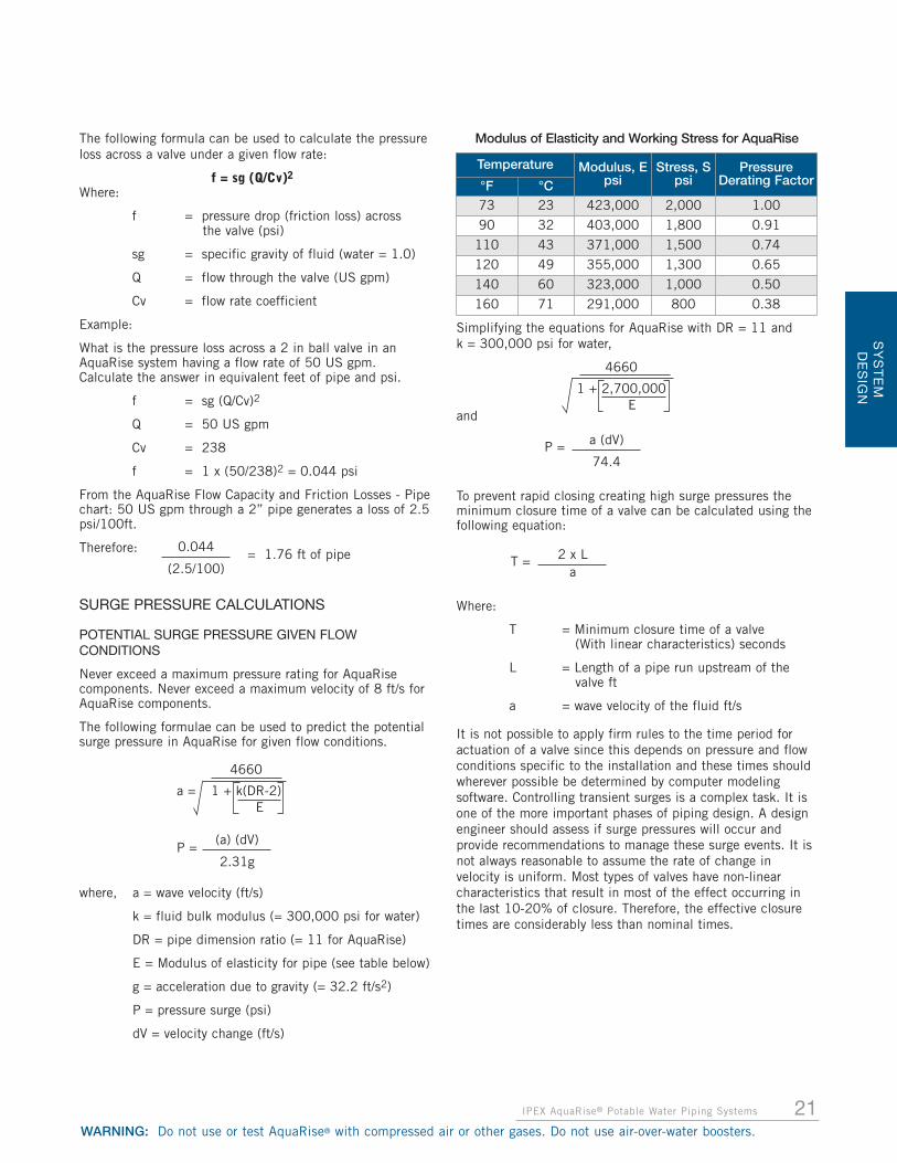
The following formula can be used to calculate the pressureloss across a valve under a given flow rate:
f = sg (Q/Cv)2
Where:
f = pressure drop (friction loss) across the valve (psi)
sg = specific gravity of fluid (water = 1.0)
Q = flow through the valve (US gpm)
Cv = flow rate coefficient
Example:
What is the pressure loss across a 2 in ball valve in anAquaRise system having a flow rate of 50 US gpm. Calculate the answer in equivalent feet of pipe and psi.
f = sg (Q/Cv)2
Q = 50 US gpm
Cv = 238
f = 1 x (50/238)2 = 0.044 psi
From the AquaRise Flow Capacity and Friction Losses - Pipechart: 50 US gpm through a 2” pipe generates a loss of 2.5psi/100ft.
Therefore:
SURGE PRESSURE CALCULATIONS
POTENTIAL SURGE PRESSURE GIVEN FLOWCONDITIONS
Never exceed a maximum pressure rating for AquaRisecomponents. Never exceed a maximum velocity of 8 ft/s forAquaRise components.
The following formulae can be used to predict the potentialsurge pressure in AquaRise for given flow conditions.
where, a = wave velocity (ft/s)
k = fluid bulk modulus (= 300,000 psi for water)
DR = pipe dimension ratio (= 11 for AquaRise)
E = Modulus of elasticity for pipe (see table below)
g = acceleration due to gravity (= 32.2 ft/s2)
P = pressure surge (psi)
dV = velocity change (ft/s)
Simplifying the equations for AquaRise with DR = 11 and k = 300,000 psi for water,
and
To prevent rapid closing creating high surge pressures theminimum closure time of a valve can be calculated using thefollowing equation:
Where:
T = Minimum closure time of a valve (With linear characteristics) seconds
L = Length of a pipe run upstream of the valve ft
a = wave velocity of the fluid ft/s
It is not possible to apply firm rules to the time period foractuation of a valve since this depends on pressure and flowconditions specific to the installation and these times shouldwherever possible be determined by computer modelingsoftware. Controlling transient surges is a complex task. It isone of the more important phases of piping design. A designengineer should assess if surge pressures will occur andprovide recommendations to manage these surge events. It isnot always reasonable to assume the rate of change invelocity is uniform. Most types of valves have non-linearcharacteristics that result in most of the effect occurring inthe last 10-20% of closure. Therefore, the effective closuretimes are considerably less than nominal times.
2 x La
T =
1 + 2,700,000E
4660
0.044
(2.5/100)
1 + k(DR-2)E
4660
(a) (dV)
2.31g
a (dV)
74.4P =
a =
P =
= 1.76 ft of pipe
Modulus of Elasticity and Working Stress for AquaRise
Temperature Modulus, Epsi
Stress, Spsi
PressureDerating Factor°F °C
73 23 423,000 2,000 1.00
90 32 403,000 1,800 0.91
110 43 371,000 1,500 0.74
120 49 355,000 1,300 0.65
140 60 323,000 1,000 0.50
160 71 291,000 800 0.38

Example: A cold water flow of 35 US gpm in 2" AquaRise issuddenly stopped due to a rapid valve closure. The run is250 ft long. The system pressure is 100 psi at 73ºF. Whatpotential water hammer (surge pressure) could be generated?
Solution: First calculate the system velocity using velocityformula presented earlier,
Next, we must determine the value of E for cold water flow.By referring to table above, select the lowest temperaturevalue (T= 73˚F) where E = 423,000 psi.
Now wave velocity ‘a’ can be calculated:
Now calculate surge pressure,
Thus, the potential surge pressure for this piping system would be 89.7 psi.
Therefore, the total line pressure that the piping system couldsee would be 100 psi (static pressure) + 89.7 psi (surge pressure)= 189.7 psi.
It is also interesting to note that a similar calculation for 2"Type L copper at 35 US gpm would yield a potential surgepressure of 285 psi (100 static pressure + 185 surge pressure)due to the higher rigidity of the copper pipe.
1.What is the minimum valve closure time required toprevent an instantaneous pressure surge?
Solution:
From the previous example, the total line pressure that thepiping could see would be 100 psi + 89.7 psi = 189.7 psi.
To prevent the system from seeing this pressure the followingminimum closure time is required:
THRUST FORCES
Thrust forces can occur at any point in a piping system wherethe directional or cross-sectional area of the waterwaychanges or where additional structure loads, such as valves,are installed. These forces must be accommodated by meansof reinforcement using anchors, riser clamps, or restraininghangers.
The size or need for reinforcements should be based on thedesign engineer’s evaluation of flow velocities and pressureincreases due to the fluid’s momentum.
Note: the thrust created at unrestrained fittings can beconsiderable (as shown in table below) and must beaddressed during installation.
22 IPEX AquaRise® Potable Water Piping Systems
WARNING: Do not use or test AquaRise® with compressed air or other gases. Do not use air-over-water boosters.
SY
ST
EM
DE
SIG
N
Size Blank Ends and Junctions 90° Bends 45° Bends
1/2 60 85 503/4 90 130 701 140 200 110
1-1/4 220 320 1701-1/2 300 420 230
2 450 630 3452-1/2 650 910 500
3 970 1,360 7454 1,600 2,240 1,225
Thrust at Fittings in Pounds per 100 psi of Internal Pressure
One Ft/s Surge Pressures vs. Temperature
The following table represents the resultant surge pressurefor a 1 ft/s instantaneous velocity change (i.e. start-up orshutdown) in AquaRise pipe at varying operatingtemperatures. The surge pressure values in this table can bemultiplied by the actual system velocity to obtain potentialsurge pressures for that velocity. For example, if V = 3.5 ft/s,then the potential surge for that system would be the tablevalue x 3.5.
Never exceed a maximum velocity of 8 ft/s
Operating Temperature One Ft/s Surge Pressure
°F °C (psi) (kPa)73 23 24.1 166.290 32 23.6 162.7
110 43 22.8 157.2120 49 22.3 153.8140 60 21.4 147.5160 71 20.5 141.3
V = (0.4085)Q
di2
= = 3.89 ft/s(0.4085) (35)1.9172
a = = 1,715 ft/s
P = = 89.7 psi
1+ 2,700,000423,000
4660
(1715) x (3.89)74.4
T = 2 x 250 ft
1715 ft/sT = 0.29 seconds

23IPEX AquaRise® Potable Water Piping Systems
WARNING: Do not use or test AquaRise® with compressed air or other gases. Do not use air-over-water boosters.
SY
ST
EM
DE
SIG
N
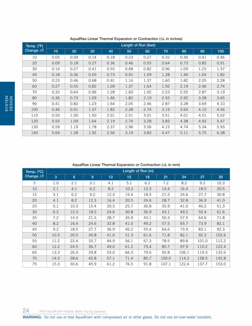
EXPANSION AND CONTRACTION DESIGNAs with all construction materials, AquaRise pipingundergoes expansion and contraction when subjected tochanges in temperature. The coefficient of linear expansionfor AquaRise is 3.8 x 10⁻⁵ in/in/°F which corresponds to achange in length of 0.456 in per 10°F temperature changeper 100 ft. of pipe length.
CALCULATING EXPANSION AND CONTRACTION
Determine the total amount of expansion that any particularstraight section of piping will undergo. To do this, theformula below should be used:
Where, Δ L = change in length due to temp. variance (in.)
Y = expansion coefficient for AquaRise (0.456 in / 10°F / 100 ft.)
T = initial system installation temperature (°F)
F = final system operating temperature (°F)
L = length of straight section (ft.)
For reference, a table of expansion values is presented on thefollowing page for various temperature changes and pipesection (run) lengths. Note that these expansion lengthvalues are independent of pipe size.
Failure to properly design and accommodate for expansionand contraction due to temperature changes can lead to
system failure. Follow all IPEX recommendations for accommodating
expansion and contraction.
(T - F)
10
L
100Δ L = Y x x
NOTICE
NOTICE
Designers and installers must anticipate and account for the total change in temperature (ΔT) between the date of installation and the peak temperature the AquaRise
system will see. As an example, for installations at 40°F (5°C), in combination with usage at the maximum
operating system temperature of 160°F (71°C), the AquaRise systems would see a ΔT as high as
120°F (66°C).
24 IPEX AquaRise® Potable Water Piping Systems
WARNING: Do not use or test AquaRise® with compressed air or other gases. Do not use air-over-water boosters.
Temp. (ºF)Change ΔT
Length of Run (feet)
10 20 30 40 50 60 70 80 90 100
10 0.05 0.09 0.14 0.18 0.23 0.27 0.32 0.36 0.41 0.46
20 0.09 0.18 0.27 0.36 0.46 0.55 0.64 0.73 0.82 0.91
30 0.14 0.27 0.41 0.55 0.68 0.82 0.96 1.09 1.23 1.37
40 0.18 0.36 0.55 0.73 0.91 1.09 1.28 1.46 1.64 1.82
50 0.23 0.46 0.68 0.91 1.14 1.37 1.60 1.82 2.05 2.28
60 0.27 0.55 0.82 1.09 1.37 1.64 1.92 2.19 2.46 2.74
70 0.32 0.64 0.96 1.28 1.60 1.92 2.23 2.55 2.87 3.19
80 0.36 0.73 1.09 1.46 1.82 2.19 2.55 2.92 3.28 3.65
90 0.41 0.82 1.23 1.64 2.05 2.46 2.87 3.28 3.69 4.10
100 0.46 0.91 1.37 1.82 2.28 2.74 3.19 3.65 4.10 4.56
110 0.50 1.00 1.50 2.01 2.51 3.01 3.51 4.01 4.51 5.02
120 0.55 1.09 1.64 2.19 2.74 3.28 3.83 4.38 4.92 5.47
130 0.59 1.19 1.78 2.37 2.96 3.56 4.15 4.74 5.34 5.93
140 0.64 1.28 1.92 2.56 3.19 3.83 4.47 5.11 5.75 6.38
Temp. (ºC)Change ΔT
Length of Run (m)
3 6 9 12 15 18 21 24 27 30
5 1.0 2.1 3.1 4.1 5.1 6.2 7.2 8.2 9.2 10.3
10 2.1 4.1 6.2 8.2 10.3 12.3 14.4 16.4 18.5 20.5
15 3.1 6.2 9.2 12.3 15.4 18.5 21.5 24.6 27.7 30.8
20 4.1 8.2 12.3 16.4 20.5 24.6 28.7 32.8 36.9 41.0
25 5.1 10.3 15.4 20.5 25.7 30.8 35.9 41.0 46.2 51.3
30 6.2 12.3 18.5 24.6 30.8 36.9 43.1 49.2 55.4 61.6
35 7.2 14.4 21.5 28.7 35.9 43.1 50.3 57.5 64.6 71.8
40 8.2 16.4 24.6 32.8 41.0 49.2 57.5 65.7 73.9 82.1
45 9.2 18.5 27.7 36.9 46.2 55.4 64.6 73.9 83.1 92.3
50 10.3 20.5 30.8 41.0 51.3 61.6 71.8 82.1 92.3 102.6
55 11.2 22.4 33.7 44.9 56.1 67.3 78.5 89.8 101.0 112.2
60 12.2 24.5 36.7 49.0 61.2 73.4 85.7 97.9 110.2 122.4
65 13.3 26.5 39.8 53.0 66.3 79.6 92.8 106.1 119.3 132.6
70 14.3 28.6 42.8 57.1 71.4 85.7 100.0 114.2 128.5 142.8
75 15.3 30.6 45.9 61.2 76.5 91.8 107.1 122.4 137.7 153.0
AquaRise Linear Thermal Expansion or Contraction (ΔL in mm)
AquaRise Linear Thermal Expansion or Contraction (ΔL in inches)
SY
ST
EM
DE
SIG
N

ACCOMMODATING EXPANSION ANDCONTRACTION
After determining the amount of expansion or contraction tobe expected in the AquaRise piping system, designers andinstallers must choose a method to accommodate themovement. Below are the acceptable methods foraccommodating expansion and contraction.
1. EXPANSION LOOPS
It is very important to properly size expansion loops. Under-sizing a loop in any of its critical dimensions will actuallyincrease stresses in the system. Diagrams for an expansionloop, sample loop calculations, and reference charts areshown below:
The critical length “ℓ” must be calculated in order to designthe expansion loop. At ipexaquarise.com there is aconvenient “ℓ” dimension calculator.
To calculate “ℓ” manually, the following formula can be used:
Where, ℓ = critical length (in.)
E = Modulus of Elasticity for AquaRise at maximum operating temperature (psi)
D = outside diameter of pipe (in.)
ΔL = change in length due to expansion (in.)
S = working stress at maximum operating temperature (psi)
Example: For a run of 90 ft. of 3” nominal size AquaRisepipe, installed at 65°F and operating at 140°F, how longshould the loop legs be for an expansion loop in order tocompensate for the system expansion?
Step 1: Calculate the amount of expansion to be expected.
ΔL = Y x x
Known: L = 90 ft, T = 140°F, F = 65°F,
Y = 0.456 in/10°F/100 ft
(Coefficient of Thermal Expansion)
ΔL = 0.456 x x
ΔL = 3.08 in.
Step 2: Calculate the critical expansion loop length
Known: ΔL = 3.08 in., E = 323,000 psi, S = 1000 psi
(from Surge Pressure Section – Modulus of Elasticity &Working Stress for AquaRise), D = 3.5 in (OD, from physicaldimension and weights section)
ℓ =
ℓ = 102.2 inches
Therefore: 0.7ℓ = 71.5 in. and 0.35ℓ = 35.8 in.
Placement of Expansion Loops
Expansion loops for AquaRise shall be centered along thepipe run in which they are installed. For example, if 2 loopsare required in a section, they should be placed as close aspossible to be 1/3 and 2/3 along the pipe section.
25IPEX AquaRise® Potable Water Piping Systems
WARNING: Do not use or test AquaRise® with compressed air or other gases. Do not use air-over-water boosters.
SY
ST
EM
DE
SIG
N
0.7ℓ
0.35ℓ
Loopmin6" 6"
min
(To be placed at the mid-point of the pipe run)
: Guide or Hanger
: Anchor
(T - F)
10
L
100
90
100
(140 - 65)
10
3 x 323,000 x 3.5 x 3.081000
ℓ = 3ED(ΔL)S
ℓ = 3ED(ΔL)S

SY
STE
M D
ES
IGN
26 IPEX AquaRise® Potable Water Piping Systems
WARNING: Do not use or test AquaRise® with compressed air or other gases. Do not use air-over-water boosters.
2. CHANGE OF DIRECTION
A simple change of direction can also effectively relievestress caused by thermal expansion/contraction, but as withexpansion loops, the ‘ℓ’ dimension is just as critical. Tooshort a distance to a guide will reduce the flexibility in thesystem. ‘ℓ’ can be calculated as was shown in the previousloops section.
Using the previous example, the critical dimension ℓ = 102.2 in
3. OFFSETS
Offsets are similar to loops and changes of directions, andthe critical ℓ dimension is calculated in the same way. Unlikea loop, no restraint should be placed between the guides.
Using the previous example, the critical dimension 0.5ℓ = 51.1 in., and ℓ = 102.2 in
Change of direction
ℓ: Guide or Hanger
Offset
0.5ℓ
0.5ℓ
ℓ: Guide or Hanger

27IPEX AquaRise® Potable Water Piping Systems
SY
STE
M D
ES
IGN
WARNING: Do not use or test AquaRise® with compressed air or other gases. Do not use air-over-water boosters.
NOTES_________________________________________
_________________________________________
_________________________________________
_________________________________________
_________________________________________
_________________________________________
_________________________________________
_________________________________________
_________________________________________
_________________________________________
_________________________________________
_________________________________________
_________________________________________
_________________________________________
_________________________________________
_________________________________________
_________________________________________
_________________________________________
_________________________________________
_________________________________________
_________________________________________
_________________________________________
_________________________________________
_________________________________________
_________________________________________
_________________________________________
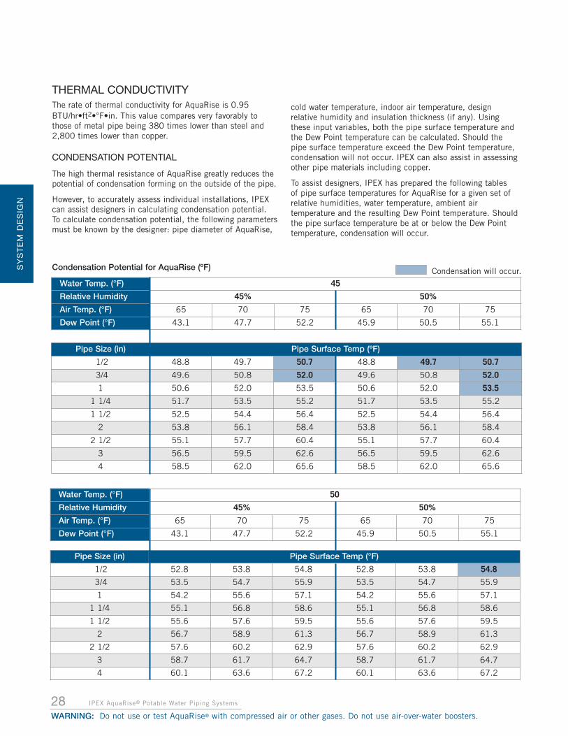
Pipe Size (in) Pipe Surface Temp (ºF)
1/2 48.8 49.7 50.7 48.8 49.7 50.7
3/4 49.6 50.8 52.0 49.6 50.8 52.0
1 50.6 52.0 53.5 50.6 52.0 53.5
1 1/4 51.7 53.5 55.2 51.7 53.5 55.2
1 1/2 52.5 54.4 56.4 52.5 54.4 56.4
2 53.8 56.1 58.4 53.8 56.1 58.4
2 1/2 55.1 57.7 60.4 55.1 57.7 60.4
3 56.5 59.5 62.6 56.5 59.5 62.6
4 58.5 62.0 65.6 58.5 62.0 65.6
Water Temp. (°F) 50
Relative Humidity 45% 50%
Air Temp. (°F) 65 70 75 65 70 75
Dew Point (°F) 43.1 47.7 52.2 45.9 50.5 55.1
Pipe Size (in) Pipe Surface Temp (°F)
1/2 52.8 53.8 54.8 52.8 53.8 54.8
3/4 53.5 54.7 55.9 53.5 54.7 55.9
1 54.2 55.6 57.1 54.2 55.6 57.1
1 1/4 55.1 56.8 58.6 55.1 56.8 58.6
1 1/2 55.6 57.6 59.5 55.6 57.6 59.5
2 56.7 58.9 61.3 56.7 58.9 61.3
2 1/2 57.6 60.2 62.9 57.6 60.2 62.9
3 58.7 61.7 64.7 58.7 61.7 64.7
4 60.1 63.6 67.2 60.1 63.6 67.2
Water Temp. (°F) 45
Relative Humidity 45% 50%
Air Temp. (°F) 65 70 75 65 70 75
Dew Point (°F) 43.1 47.7 52.2 45.9 50.5 55.1
28 IPEX AquaRise® Potable Water Piping Systems
WARNING: Do not use or test AquaRise® with compressed air or other gases. Do not use air-over-water boosters.
SY
ST
EM
DE
SIG
N
THERMAL CONDUCTIVITYThe rate of thermal conductivity for AquaRise is 0.95 BTU/hr•ft2•°F•in. This value compares very favorably tothose of metal pipe being 380 times lower than steel and2,800 times lower than copper.
CONDENSATION POTENTIAL
The high thermal resistance of AquaRise greatly reduces thepotential of condensation forming on the outside of the pipe.
However, to accurately assess individual installations, IPEXcan assist designers in calculating condensation potential. To calculate condensation potential, the following parametersmust be known by the designer: pipe diameter of AquaRise,
cold water temperature, indoor air temperature, designrelative humidity and insulation thickness (if any). Usingthese input variables, both the pipe surface temperature andthe Dew Point temperature can be calculated. Should thepipe surface temperature exceed the Dew Point temperature,condensation will not occur. IPEX can also assist in assessingother pipe materials including copper.
To assist designers, IPEX has prepared the following tables of pipe surface temperatures for AquaRise for a given set ofrelative humidities, water temperature, ambient airtemperature and the resulting Dew Point temperature. Shouldthe pipe surface temperature be at or below the Dew Pointtemperature, condensation will occur.
Condensation Potential for AquaRise (ºF) Condensation will occur.
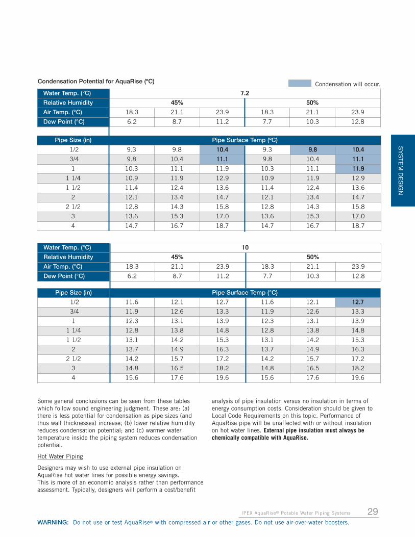
29IPEX AquaRise® Potable Water Piping Systems
SY
STE
M D
ES
IGN
WARNING: Do not use or test AquaRise® with compressed air or other gases. Do not use air-over-water boosters.
Water Temp. (°C) 10
Relative Humidity 45% 50%
Air Temp. (°C) 18.3 21.1 23.9 18.3 21.1 23.9
Dew Point (°C) 6.2 8.7 11.2 7.7 10.3 12.8
Pipe Size (in) Pipe Surface Temp (°C)
1/2 11.6 12.1 12.7 11.6 12.1 12.7
3/4 11.9 12.6 13.3 11.9 12.6 13.3
1 12.3 13.1 13.9 12.3 13.1 13.9
1 1/4 12.8 13.8 14.8 12.8 13.8 14.8
1 1/2 13.1 14.2 15.3 13.1 14.2 15.3
2 13.7 14.9 16.3 13.7 14.9 16.3
2 1/2 14.2 15.7 17.2 14.2 15.7 17.2
3 14.8 16.5 18.2 14.8 16.5 18.2
4 15.6 17.6 19.6 15.6 17.6 19.6
Pipe Size (in) Pipe Surface Temp (ºC)
1/2 9.3 9.8 10.4 9.3 9.8 10.4
3/4 9.8 10.4 11.1 9.8 10.4 11.1
1 10.3 11.1 11.9 10.3 11.1 11.9
1 1/4 10.9 11.9 12.9 10.9 11.9 12.9
1 1/2 11.4 12.4 13.6 11.4 12.4 13.6
2 12.1 13.4 14.7 12.1 13.4 14.7
2 1/2 12.8 14.3 15.8 12.8 14.3 15.8
3 13.6 15.3 17.0 13.6 15.3 17.0
4 14.7 16.7 18.7 14.7 16.7 18.7
Water Temp. (°C) 7.2
Relative Humidity 45% 50%
Air Temp. (°C) 18.3 21.1 23.9 18.3 21.1 23.9
Dew Point (°C) 6.2 8.7 11.2 7.7 10.3 12.8
Condensation Potential for AquaRise (ºC) Condensation will occur.
Some general conclusions can be seen from these tableswhich follow sound engineering judgment. These are: (a)there is less potential for condensation as pipe sizes (andthus wall thicknesses) increase; (b) lower relative humidityreduces condensation potential; and (c) warmer watertemperature inside the piping system reduces condensationpotential.
Hot Water Piping
Designers may wish to use external pipe insulation onAquaRise hot water lines for possible energy savings. This is more of an economic analysis rather than performanceassessment. Typically, designers will perform a cost/benefit
analysis of pipe insulation versus no insulation in terms ofenergy consumption costs. Consideration should be given toLocal Code Requirements on this topic. Performance ofAquaRise pipe will be unaffected with or without insulationon hot water lines. External pipe insulation must always bechemically compatible with AquaRise.

SY
STE
M D
ES
IGN
30 IPEX AquaRise® Potable Water Piping Systems
WARNING: Do not use or test AquaRise® with compressed air or other gases. Do not use air-over-water boosters.
CHEMICAL RESISTANCEAquaRise is solely intended for use in hot or cold potablewater distribution.
The TempRite® Technology CPVC compound used to makeAquaRise pipe, valves and fittings can be damaged bycontact with chemicals found in some construction products.Care must be taken to ensure that products contactingAquaRise are chemically compatible.
Ensure chemical compatibility with AquaRise by checkingwith IPEX and the manufacturers of such common pipingsystem components as:
• fire stop materials
• pipe insulation and adhesives
• heat trace cables
• wear pads or other rubber components
• thread sealants
The general information below gives an overview of chemicalcompatibility concerns for AquaRise potable water piping.
AquaRise Solvent Cements and Primers - These productsare designed for use in joining AquaRise by way of solventwelding. The application of these products should be limitedto the spigot-socket connection surfaces of a particular joint.Widespread or careless application of cement or primer toother parts of the piping system may cause softening andweakened structural areas in the piping and must be avoided.
Flexible Wire and Cables - These products may containplasticizers (also called softeners) which if in contact withAquaRise may impose harm in the form of environmentalstress cracking.
Rubber and Flexible Materials - For the same reasons aswith flexible wires and cables, care must be taken whenAquaRise is installed in direct contact with gaskets, electricaltape, hanger padding, vinyl dipped metal parts and flexiblehoses or tubes. Plasticizers contained in these substancesmay impose harm to AquaRise when in direct contact.
Fungicides and Mold Inhibitors - If ever applying theseproducts in close proximity to AquaRise piping during waterdamage or mold cleanup, isolate the piping from theseproducts by use of an external wrap or sleeve. Avoid directcontact of these products with AquaRise.
Grease and Cooking Oils - If pipe is installed in a kitchenenvironment, avoid direct or airborne contact with grease orcooking oils.
Leak Detection Substances - Products such as dishwashingliquids with synthetic detergents along with odor emittingproducts such as colognes, perfumes or scented oils all mustbe avoided from contacting AquaRise due to their highcontent of solvents which are potentially harmful toAquaRise.
Proximity to Metal Piping - Some potential harmful effectsto AquaRise from nearby installation of metallic pipinginclude burning from contact with torches or molten materialand solder flux, and incompatible thread sealants, residualoils, lubricants or leak detectors all of which may becommonly used on metal piping.
Paint - Only water-based latex paint may be used onAquaRise should the piping ever need to be painted. DO NOTUSE oil-based paints with AquaRise.
Polyurethane Spray-On Foams - Some of these productshave been tested to be compatible for direct contact withAquaRise piping. However, the manner in which they areapplied is important. To minimize heat applied to AquaRisedue to exothermic heat release by the foam, it is stronglyrecommended that foam be applied in a maximum layerthickness of 2 inches (50 mm) and that a time lapse of 10minutes between application of layers is observed. Furtherinformation on these products may be obtained from theSpray Polyurethane Foam Alliance (SPFA).
If chemical compatibility with AquaRise is in question, IPEXrecommends isolating the suspect product from contact withAquaRise pipe, valves or fittings.
Packing Oils and Pump Grease - Equipment containingpacking oil and pump grease must be thoroughly flushed withwater before connecting to an AquaRise piping system.
31IPEX AquaRise® Potable Water Piping Systems
INS
TALLATIO
N
WARNING: Do not use or test AquaRise® with compressed air or other gases. Do not use air-over-water boosters.
Always follow the complete AquaRise installation instructionsprovided in this manual. Failure to comply with handling,storage and installation instructions may cause piping systemfailure resulting in damage to property.
SAFE HANDLING AND STORAGE OF PIPE,FITTINGS & VALVESCare must be taken when handling AquaRise products toensure that pipe, fittings, valves and accessories are notdamaged prior to installation. Take the following precautionsto ensure AquaRise products remain in top condition prior toinstallation.
• Store pipe indoors if possible
• Pipe stored outside must be covered with a well-ventilated white tarp
• Always keep pipe clean and covered in its originalpackaging
• Always store pipe on a flat surface and never store otherproducts on top of pipe
• Do not drop or drag pipe
• Always store fittings and valves indoors in originalpackaging or repackage to protect from damage, dirt anddebris
• Inspect all AquaRise products prior to installation
• Never install AquaRise products that are damaged
SOLVENT WELDINGINTRODUCTION
Creating optimal solvent welded connections requiresattention to detail, proper preparation of components and anunderstanding of all instructions provided in this manual.
SAFE HANDLING AND STORAGE OF PRIMERS ANDSOLVENT CEMENTS
AquaRise primer and solvent cement are made fromflammable liquids and must be kept away from all sources ofignition. Good ventilation must be maintained to reduce firehazard and to minimize the breathing of solvent vapors. Referto ASTM F402, Standard Practice for Safe Handling ofSolvent Cements, Primers, and Cleaners Used for JoiningThermoplastic Pipe and Fittings. Always adhere to localjobsite and workplace safety regulations. For additional safetyinformation, consult the material safety data sheet for thisproduct which is available at ipexaquarise.com.
• Always provide proper ventilation when applying primersand cements
• Avoid skin or eye contact with primers and cements
• Wash immediately if contact occurs to avoid prolongedexposure
• Do not solvent weld joints near open flames or solderingtorches
• Use personal protection equipment (PPE) when handlingprimers and solvent cements
• Always store primer and cement indoors
• For cold weather installation store primer and cement in awarm location above 40ºF (5ºC)
• For hot weather installation store primer and cement in acool, shaded location
• Always check bottom of primer and cement cans for dateof manufacture and expiry date
• Never use solvent cement that is older than itsrecommended shelf life. Use before the expiry date orwithin 2 years of the manufacturing date stamped on thebottom of the can
• Never use primer that is older than its recommendedshelf life. Use before the expiry date or within 3 years ofthe manufacturing date stamped on the bottom of thecan
• Properly discard primer and cement that exceeds itsrecommended shelf life or expiry date
• Properly discard solvent cement that has hardened orjelled
• Tightly close partially used primer and cement containers
SOLVENT WELDING BASICS
• Dry fit all joints prior to solvent welding to confirm properinterference fit
• Discard fitting joints without proper interference fit
• Do not solvent weld joints that are too loose or too tight
• Always use AquaRise bevelling tools to prepare pipe endsbefore cementing
• Do not solvent weld joints without first bevelling pipe ends
• Use only AquaRise primer and solvent cements inaccordance with IPEX instructions
• Do not use other cements to connect AquaRise pipe,fittings and accessories
• Follow all solvent welding instructions provided with thisproduct
• Follow all AquaRise installation instructions. Visitipexaquarise.com for details
SECTION 3: INSTALLATION
WARNINGDuring the curing of the solvent welded joints, vapors may
accumulate inside the piping system, especially shouldone end of the line be capped. Nearby sparks from
welders or torches may inadvertently ignite these vaporsand create a hazardous incident. Attention must be givento removing all vapors using air-blowers or water flushing
prior to capping one end of an empty piping system.
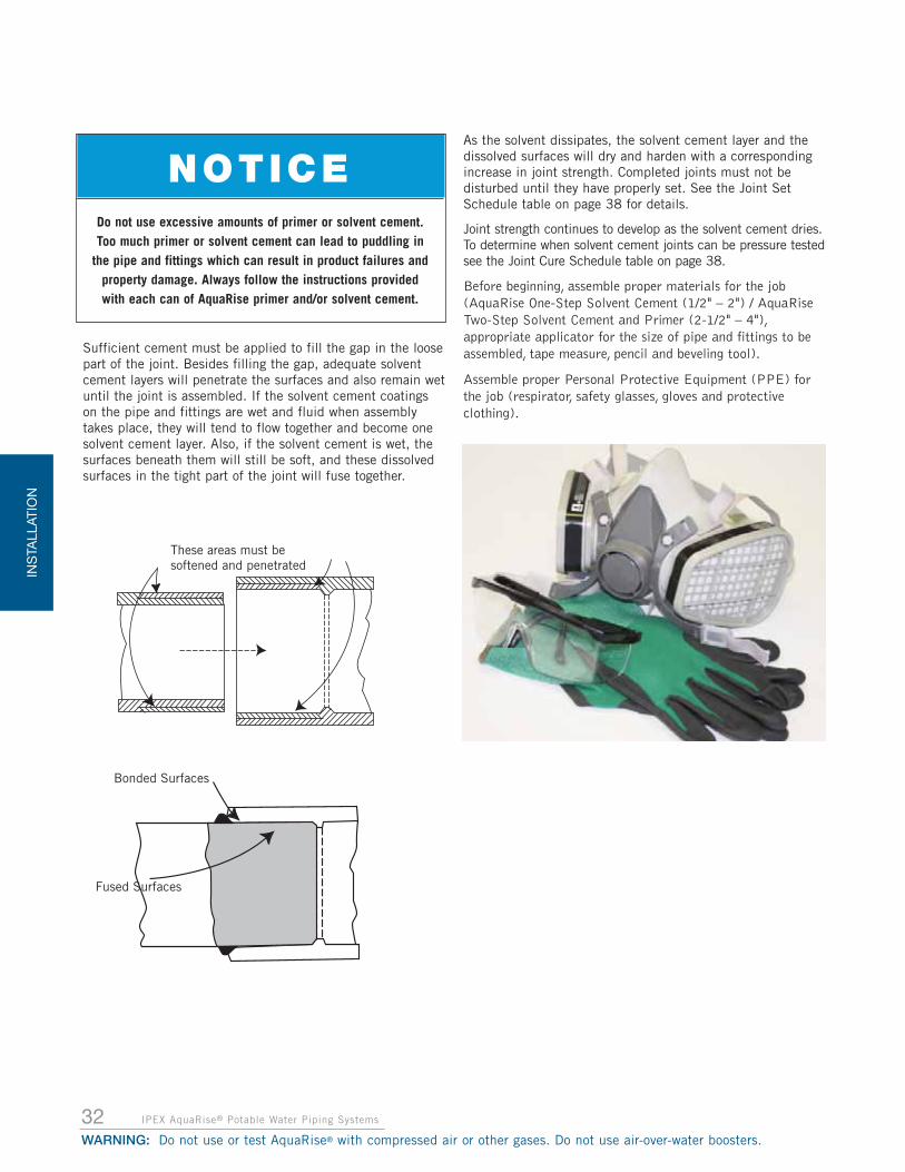
INS
TALL
ATIO
N
IPEX AquaRise® Potable Water Piping Systems
WARNING: Do not use or test AquaRise® with compressed air or other gases. Do not use air-over-water boosters.
Sufficient cement must be applied to fill the gap in the loosepart of the joint. Besides filling the gap, adequate solventcement layers will penetrate the surfaces and also remain wetuntil the joint is assembled. If the solvent cement coatingson the pipe and fittings are wet and fluid when assemblytakes place, they will tend to flow together and become onesolvent cement layer. Also, if the solvent cement is wet, thesurfaces beneath them will still be soft, and these dissolvedsurfaces in the tight part of the joint will fuse together.
As the solvent dissipates, the solvent cement layer and thedissolved surfaces will dry and harden with a correspondingincrease in joint strength. Completed joints must not bedisturbed until they have properly set. See the Joint SetSchedule table on page 38 for details.
Joint strength continues to develop as the solvent cement dries.To determine when solvent cement joints can be pressure testedsee the Joint Cure Schedule table on page 38.
Before beginning, assemble proper materials for the job(AquaRise One-Step Solvent Cement (1/2" – 2") / AquaRiseTwo-Step Solvent Cement and Primer (2-1/2" – 4"),appropriate applicator for the size of pipe and fittings to beassembled, tape measure, pencil and beveling tool).
Assemble proper Personal Protective Equipment (PPE) forthe job (respirator, safety glasses, gloves and protectiveclothing).
These areas must besoftened and penetrated
Bonded Surfaces
Fused Surfaces
Do not use excessive amounts of primer or solvent cement.Too much primer or solvent cement can lead to puddling in
the pipe and fittings which can result in product failures andproperty damage. Always follow the instructions providedwith each can of AquaRise primer and/or solvent cement.
NOTICE
32

33IPEX AquaRise® Potable Water Piping Systems
INS
TALLATIO
N
WARNING: Do not use or test AquaRise® with compressed air or other gases. Do not use air-over-water boosters.
SOLVENT WELDING INSTRUCTIONS
1. CUTTING THE PIPE
It is important to cut the pipe squarely. A square cut providesthe surface of the pipe with the maximum bonding area. Pipecan be easily cut with a wheel-type plastic tubing cutter,chop saw or fine toothed saw. Do not use reciprocating saws.Tools used to cut pipe must be designed for AquaRise pipingand must be in good condition in accordance with the toolmanufacturer’s recommendations. If there is any indication ofpipe damage or evidence of pipe end cracking, cut off atleast 2 inches (50mm) beyond any visible crack. Use of
ratchet cutters is notrecommended as they may splitthe pipe if not properly used andmaintained.
2. PREPARING PIPE ENDS
Always bevel pipe ends. Use the tools provided by IPEXwhich have been specifically designed for this purpose.Remove burrs and filings from the inside of the pipe using aknife edge or file.
3. CLEANING
Using a clean dry cloth, wipe any dirt and moisture from thefitting socket and the pipe end.
4. DRY-FITTING
Before applying primer or solvent cement, test allconnections (pipe, fittings and accessories) to confirm aproper interference fit exists. Dry-fit contact between properlybevelled pipe and fitting sockets is essential in making agood joint. The bevelled pipe should easily enter the fittingsocket and make contact with the inner fitting socket wallbefore bottoming out. A proper interference fit is presentwhen the bevelled pipe can only be inserted 1/3 to 2/3 of theway into the fitting socket.
Do not solvent weld pipe, fittings or accessories that fitloosely together or where pipe bottoms out. Proper jointstrength cannot be developed.
Do not solvent weld pipe, fittings or accessories if a bevelledpipe cannot easily be inserted at least 1/3 of the way into thefitting socket. This may cause excessive stresses duringassembly leading to joint failure.
5. APPLICATOR SIZEUse the applicators (daubers and swabs) provided withAquaRise solvent cements and in accordance with theseinstructions. Proper applicator size is critical to ensuring thecorrect amount of AquaRise primer and/or solvent cement isapplied to the pipe, fittings and accessories.
2”
CUT HERE
AquaRise beveling tool1/2" to 1" diameter
AquaRise beveling tool1-1/4" to 4" diameter

INS
TALL
ATIO
N
34 IPEX AquaRise® Potable Water Piping Systems
WARNING: Do not use or test AquaRise® with compressed air or other gases. Do not use air-over-water boosters.
ONE-STEP SOLVENT WELDING PROCEDURE FOR 1/2" TO 2” DIAMETERS
IMPORTANT: For 1/2” to 2” diameters use only AquaRiseOne-Step (Yellow) solvent cement. Do not use primer withOne-Step solvent cement.
2
5
1
3
4
■ Measure the fitting socket inner depth and mark theoutside of the pipe with this dimension. This will help withapplication of the proper amount of solvent cement on thepipe and also helps indicate full and proper insertion of thepipe inside the fitting socket.
■ AquaRise One-Step cement comes with a small dauberinside the can. Use this small dauber for 1/2", 3/4" and 1"diameter joints. A larger dauber is also provided separatelyinside this carton. Use the larger dauber for 1-1/4", 1-1/2"and 2" diameter joints.
Do not use the larger dauber for 1/2", 3/4" and 1" joints.Joint failure can occur if excessive amounts of One-Stepcement are applied. Do not permit One-Step cement to poolinside of fittings or accessories.
Do not use the small dauber on 1-1/4", 1-1/2" and 2" joints.Sufficient One-Step cement must be applied in a timelymanner and kept wet prior to assembly of the joint.
■ Apply a medium layer of AquaRise One-Step solventcement to the bevelled pipe end. Apply enough cement tojust cover the socket insertion mark on the outside of thepipe. Be aggressive and work One-Step cement onto the pipesurface. Apply enough solvent cement to fill the gap betweenthe pipe and fitting to soften the surfaces.
■ Apply a thin, light layer of AquaRise One-Step solventcement to the inside of the fitting socket and work this thinlayer of One-Step cement into the wall of the fitting socket.For smaller diameters it may not be necessary to re-dip thedauber. A thin layer will prevent puddling of the One-Stepsolvent cement inside of the pipe or fitting. Excessive solventcement applied to the fitting socket can cause the joint toclog and the wall of the pipe or fitting to weaken due tosoftening by the trapped solvents.
■ Without delay, while the One-Step solvent cement is stillwet, assemble the pipe and fitting, and twist 1/8 to 1/4 turnas the pipe is being inserted. Once the pipe end has reachedthe bottom of the fitting socket, do not turn any further;doing so could break any fusion that is starting to occur.
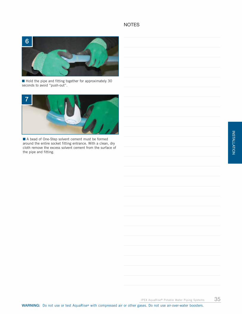
35IPEX AquaRise® Potable Water Piping Systems
INS
TALLATIO
N
WARNING: Do not use or test AquaRise® with compressed air or other gases. Do not use air-over-water boosters.
NOTES
6
7
■ Hold the pipe and fitting together for approximately 30seconds to avoid “push-out”.
■ A bead of One-Step solvent cement must be formedaround the entire socket fitting entrance. With a clean, drycloth remove the excess solvent cement from the surface ofthe pipe and fitting.

INS
TALL
ATIO
N
36 IPEX AquaRise® Potable Water Piping Systems
WARNING: Do not use or test AquaRise® with compressed air or other gases. Do not use air-over-water boosters.
TWO-STEP SOLVENT WELDING PROCEDURE FOR 2-1/2" TO 4" DIAMETERS
IMPORTANT: For 2-1/2" to 4" diameters always useAquaRise (Clear) primer with AquaRise Two-Step (Yellow)solvent cement.
1
3
2
■ Measure the fitting socket depth and mark the outside ofthe pipe with this dimension. This will help with applicationof the proper amount of primer and Two-Step solvent cementon the pipe and also helps indicate full and proper insertionof the pipe inside the fitting socket.
■ Apply AquaRise primer to the inside of the fitting socket.Use the dauber supplied in the can of primer.
■ Apply AquaRise primer to the pipe end, equal to the depthof the fitting socket. Be aggressive and work the primer intothe pipe.
4
5
6
■ While the primer is still wet and the surfaces are soft, usethe swab provided to apply a full, even layer of AquaRise Two-Step solvent cement to the pipe end, equal to the depth ofthe fitting socket. Like the primer, be aggressive and work thecement into the pipe. Remember to apply enough Two-Stepsolvent cement to fill the gap between the pipe and fitting.
■ Apply AquaRise primer to the inside of the fitting socketagain.
■ Apply a thin layer of AquaRise Two-Step solvent cement tothe inside of the fitting socket. This will prevent puddling ofthe solvent cement inside of the pipe or fitting. Excessivesolvent cement applied to the fitting socket can cause thejoint to clog and the wall of the pipe or fitting to weaken dueto softening by the trapped solvents.
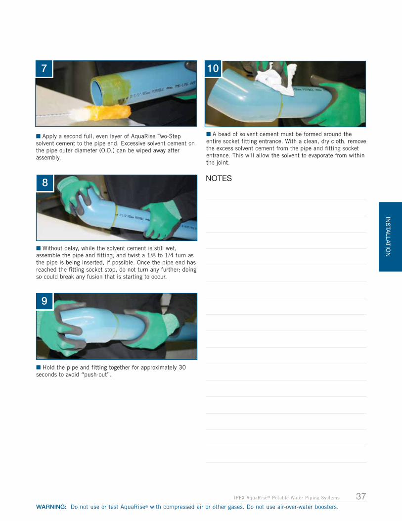
37IPEX AquaRise® Potable Water Piping Systems
INS
TALLATIO
N
WARNING: Do not use or test AquaRise® with compressed air or other gases. Do not use air-over-water boosters.
8
9
10
■ Without delay, while the solvent cement is still wet,assemble the pipe and fitting, and twist a 1/8 to 1/4 turn asthe pipe is being inserted, if possible. Once the pipe end hasreached the fitting socket stop, do not turn any further; doingso could break any fusion that is starting to occur.
■ A bead of solvent cement must be formed around theentire socket fitting entrance. With a clean, dry cloth, removethe excess solvent cement from the pipe and fitting socketentrance. This will allow the solvent to evaporate from withinthe joint.
■ Hold the pipe and fitting together for approximately 30seconds to avoid “push-out”.
7
■ Apply a second full, even layer of AquaRise Two-Stepsolvent cement to the pipe end. Excessive solvent cement onthe pipe outer diameter (O.D.) can be wiped away afterassembly.
NOTES

INS
TALL
ATIO
N
38 IPEX AquaRise® Potable Water Piping Systems
WARNING: Do not use or test AquaRise® with compressed air or other gases. Do not use air-over-water boosters.
Temperature Range
Pipe Sizes1/2" to 1-1/4"
Pipe Sizes1-1/2" to 2"
Pipe Sizes2-1/2" to 4"
60° – 100 °F(15° – 38 °C)
2 minutes 5 minutes 30 minutes
40° – 60 °F(5° – 15 °C)
5 minutes 10 minutes 2 hours
AVERAGE JOINT SET SCHEDULE FOR AQUARISE SOLVENT CEMENT**
Relative Humidity60% or Less
Cure Time Pipe Sizes1/2" to 1-1/4"
Cure Time Pipe Sizes1-1/2" to 2"
Cure Time Pipe Sizes2-1/2" to 4"
Temperature Range duringassembly and cure periods
Up to160 psi
Above160 psi
Up to160 psi
Above160 psi
Up to160 psi
Above160 psi
60° – 100 °F(15° – 38 °C)
15 min 6 hrs 30 min 12 hrs 1-1/2 hrs 24 hrs
40° – 60 °F(5° – 15 °C)
20 min 12 hrs 45 min 24 hrs 4 hrs 48 hrs
AVERAGE JOINT CURE SCHEDULE FOR AQUARISE SOLVENT CEMENT**1
Note: Initial set schedule is the necessary time to allow before the joint can be carefully handled.
** Due to the many variables in the field, these figures are to be used as a general guide only.
Note: Joint cure schedule is the necessary time to allow before pressurizing the system. In damp or humid weather allow 50%more cure time.
** Due to the many variables in the field, these figures are to be used as a general guide only.
1 Pressure values shown in this table indicate the maximum test pressure of the piping system. The system should not bepressurized at all until this cure time has elapsed.
The values provided in these charts are for guidance onlyand do not necessarily reflect the actual return to servicetime required for every situation. Installers must allow foradditional time where possible when returning AquaRisesystems to hot water service.
NOTICE

39IPEX AquaRise® Potable Water Piping Systems
INS
TALLATIO
N
WARNING: Do not use or test AquaRise® with compressed air or other gases. Do not use air-over-water boosters.
COLD WEATHER SOLVENT WELDING – BELOW 50°F (10°C)
• Do not solvent weld joints when pipe, fitting, valve orinstallation temperatures are less than 40ºF (5ºC)
• Prefabricate as much of the system as possible in aheated area
• Store AquaRise primer and solvent cement in a warmlocation above 40ºF (5ºC) when not in use and makecertain cement remains fluid
• Take special care to remove moisture including snow andice from the surfaces being joined including pipe endsand fitting and valve sockets
• Ensure that the pipe, fittings and valves are at the sametemperature prior to solvent welding
• Ensure the surfaces are softened before joining. Check forproper softening of surfaces and correct amount ofcement on a sample pipe. Surfaces are sufficientlysoftened when scraping a blade on the treated partresults in the effortless removal of a thin layer of thebase material
• Colder weather requires longer set and cure times. Referto the Tables on page 38 for required set and cureschedules before moving or pressure testing joints. Aheating blanket may be used to speed up the set andcure times
HOT WEATHER SOLVENT WELDING – ABOVE 86°F (30°C)
• Store AquaRise primer and solvent cement in a cool orshaded area prior to use
• Store pipe and fittings in a shaded area prior to solventwelding
• Cool surfaces to be joined with a clean, damp rag. Besure the surface is dry prior to solvent welding
• Consider solvent welding joints in the cooler morninghours
• Make sure both surfaces to be joined are still wet withsolvent cement when joining them together
• Vigorously stir or shake the AquaRise solvent cementbefore use
SOLVENT WELDING BALL VALVES
Solvent weld AquaRise valves using the standard solventwelding procedure outlined in this manual. To avoid damageto AquaRise valves, follow these important steps:
• Always ensure the valve handle is in the open position.Never install valves with the handle in the closed positionas this exposes the ball to dirt, damage and solventcement.
• Do not use excessive cement as it may puddle inside thevalve and interfere with valve function.
• Never allow solvent cement to contact the sealing surfaceof the union end connector or the o-ring on the valve end.Solvent cement will damage these components andprevent proper sealing. Discard any valve that has solventcement on these components.
• Always ensure AquaRise valves are properly supportedduring the solvent welding procedure. The weight of anunsupported valve may cause unwanted stress on newsolvent cement joints.
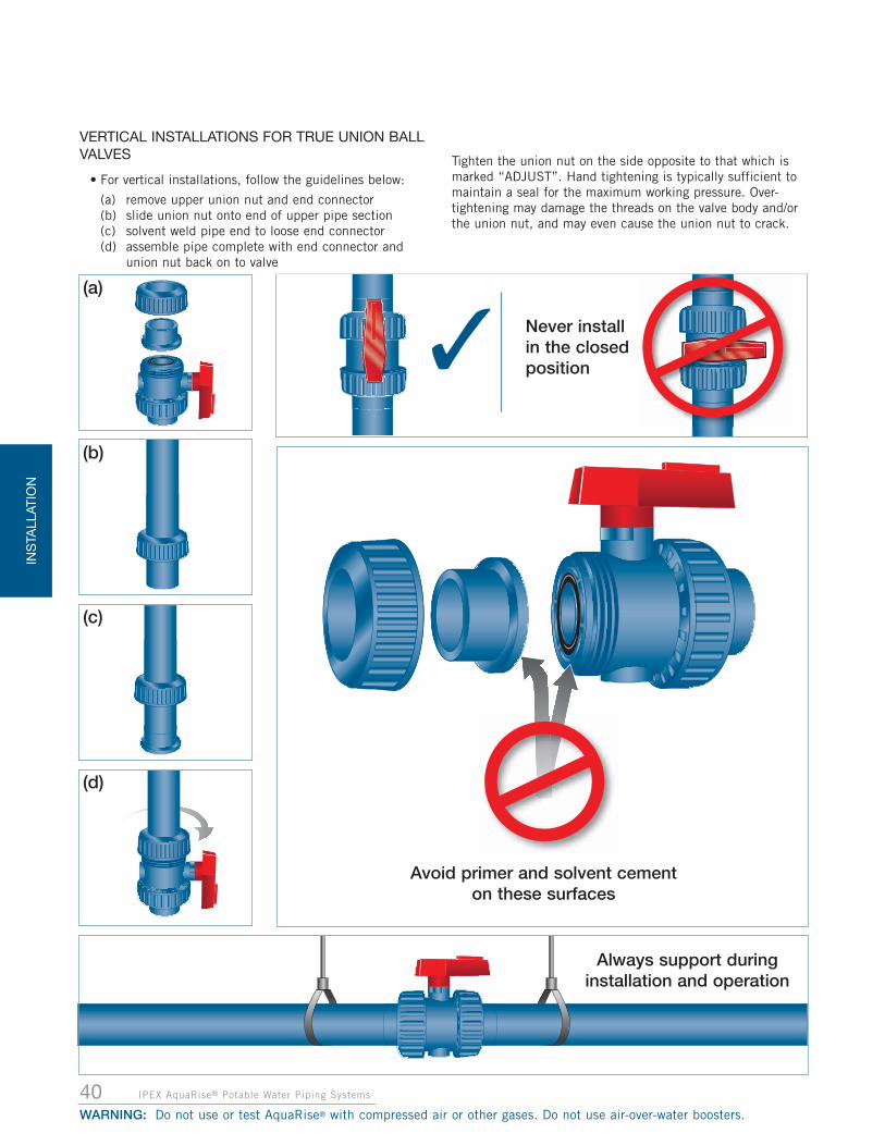
INS
TALL
ATIO
N
40 IPEX AquaRise® Potable Water Piping Systems
WARNING: Do not use or test AquaRise® with compressed air or other gases. Do not use air-over-water boosters.
✓
Avoid primer and solvent cement on these surfaces
Always support duringinstallation and operation
(a)
(b)
(c)
(d)
Never install in the closedposition
VERTICAL INSTALLATIONS FOR TRUE UNION BALLVALVES
• For vertical installations, follow the guidelines below:
(a) remove upper union nut and end connector(b) slide union nut onto end of upper pipe section(c) solvent weld pipe end to loose end connector(d) assemble pipe complete with end connector and
union nut back on to valve
Tighten the union nut on the side opposite to that which ismarked “ADJUST”. Hand tightening is typically sufficient tomaintain a seal for the maximum working pressure. Over-tightening may damage the threads on the valve body and/orthe union nut, and may even cause the union nut to crack.

41IPEX AquaRise® Potable Water Piping Systems
INS
TALLATIO
N
WARNING: Do not use or test AquaRise® with compressed air or other gases. Do not use air-over-water boosters.
FLANGE CONNECTIONSFlanges are used where periodic dismantling is required andfor convenient transition to metallic piping or componentssuch as pumps and metal valves. AquaRise flanges havesolvent cement socket ends and the same bolt holedimensions as Class 150 metal flanges per ANSI B16.5. Allflanges conform to ASTM F1970 and are made usingAquaRise fitting compound which is listed to NSF Standard61 for potable water.
Two types of AquaRise flanges are offered; solid (one-piece)flanges and Vanstone (two-piece) flanges which assist withbolt hole alignment. Both flange styles are pressure rated for 150 psi at 73°F (1,034 kPa at 23°C). When using theseflanges at elevated temperatures, the allowable operatingpressure is reduced according to thetemperature derating chart on page 7.
Flange gaskets must be installed between the AquaRise flange and its matingsurface. These gaskets are not supplied byIPEX but they are readily available. Gasketsmust be approved for potable water andmust be chemically compatible withAquaRise. They must also be full-faced
design and appropriately sized for theflange.Finally, flange gaskets must be made ofan elastomeric material with aDurometer A hardness of 50 to 70.
Full-Pressure (FP) Flange kits areavailable
to increase the operatingpressure of solid AquaRiseflanges to the same level ofAquaRise pipe and fittings –400 psi at 73°F (2,758 kPa at23°C) and 150 psi at 160°F(1,034 kPa at 71°C). These kitsconsist of a solid flange, splitmetal backing ring, connectinghardware and a NSF-61 listedelastomeric gasket.
NOTE: FP flange kits are notcompatible with two-piece Vanstone flanges.
FLANGE INSTALLATION GUIDELINES
SOLVENT WELDING FLANGES
In all cases, avoid excessive force on the solvent welded endof AquaRise flanges. Failure to properly support the flangedconnection can lead to excessive stress and failure of thesolvent weld flange connection.
If possible, complete the flange bolt connections first andensure the bolts are fully tightened in accordance with theinstructions outlined in this manual. Once this is completedand the flange is fully supported, the solvent weld connection
can be performed on the socket end of the flange. Follow allsolvent welding procedures in this manual. Ensure thesolvent welded joint is fully cured before modifying thebolted flange connection or pressure testing the system. Seethe set and cure tables shown on page 38.
If the solvent welded connection of the flange must becompleted first, ensure that the solvent welded joint is fullycured and properly supported before assembling the boltedportion of the flange. See the set and cure tables shown onpage 38.
SOLID AND VANSTONE FLANGE CONNECTIONS
1. Make sure all bolt holes of the matching flanges arealigned.
2. Ensure a proper full-faced gasket is installed betweenthe flange surfaces.
3. Make sure mating flange faces are in contact with eachother prior to tightening bolts. Do not use bolttightening to close gaps between flange faces as thiscan lead to excessive stress on the flange.
4. AquaRise Flanges can be installed against matingsurfaces that include an integrated gasket, like wafer-style butterfly valves.
5. To assist with tightening, lubricate bolt threads with alubricant fully compatible with AquaRise such as IPEXRing-Tite pipe lubricant.
6. Always tighten nuts in incremental stages following thecross star bolt tightening sequence on page 42. Alwaysuse a torque wrench to ensure values in theRecommended Torque Table are not exceeded. Uniformstress across the flange will prevent leaks.
7. Always support the flange connection and accessory(pump, valve, etc.) to eliminate potential stress.
Pipe Size(in.)
# of Holes
Bolt Diameter(in.)
Bolt Length(in.)
1/2 4 0.50 1.753/4 4 0.50 2.001 4 0.50 2.00
1-1/4 4 0.50 2.251-1/2 4 0.50 2.50
2 4 0.63 2.752-1/2 4 0.63 3.00
3 4 0.63 3.004 8 0.63 3.25
Solid and Vanstone Flanges – Bolt Dimensions
Note: Bolt length will vary if metal backing rings are used.
Solid One-Piece Flange
Vanstone Flange
Full Pressure (FP)Flange Kit

INS
TALL
ATIO
N
42 IPEX AquaRise® Potable Water Piping Systems
WARNING: Do not use or test AquaRise® with compressed air or other gases. Do not use air-over-water boosters.
CROSS STAR BOLT TIGHTENING SEQUENCE
FULL PRESSURE (FP) FLANGE KIT INSTALLATION
This kit is for installation on solid AquaRise flanges only. Donot install this kit on Vanstone flanges. This kit must beinstalled using all the components supplied. Any substitutionof components such as longer bolts or a replacement gasketmust comply with the original kit specifications. Failure tocomply with kit specifications nullifies the kit certificationand may compromise the pressure rating and flangeperformance.
INSTALLATION PROCEDURE
1. First, follow all recommended procedures shown in theSolvent Welding Flanges section of this manual.
2. Begin kit installation by placing the backing ring overthe back of the hub of the AquaRise flange, ensuringthat the bolt holes are aligned.
3. Slip the gasket provided between the two flanges andbring the AquaRise and mating flanges together.
4. Align bolt holes of back up ring, flanges and gasket.
5. The bolt threads must be well lubricated with alubricant fully compatible with AquaRise such as IPEXRing-Tite pipe lubricant.
6. Install the provided flat washers beneath each nut andthe bolt head.
7. Insert the bolts through the matching holes of both theflanges and backing ring. Use only the bolts supplied inthis kit.
8. When the bolts are installed, hand-tighten bolts untilflange faces are in light contact.
9. Using a torque wrench, placed over the nut (not on bolthead). Snug tighten the nut first, which is approximately10-15 ft-lb of torque depending on size.
10.Tighten bolts in incremental steps to the torque valuesshown in the table below. During bolt tightening use thecross star sequence previously illustrated.
11.Bolts must be tightened with a torque wrench to thefinal recommended torque values specified in the tablebelow.
12.Once this assembly is complete, perform a check passof the bolts by starting at one and going around in aclockwise direction ensuring each nut is tightened tothe highest recommended torque level for that size.
Notes:
1. AquaRise FP Flange kits can be installed againstmating surfaces that include an integrated gasket, likewafer-style butterfly valves. However, a metal “spacer”ring must be used between the valve and the FlangeKit. Longer bolts than those provided in the kit will berequired.
The bolt length will vary for flange size and assemblyconfiguration. The length of bolts supplied in this kitassumes a connection to a metal flange. For AquaRiseto AquaRise flange connections, bolts should be 1/2"longer so that the bolts extend approximately 1/4"minimum beyond the nut after final assembly.
2. This Flange assembly has been certified to ASTMF1970. As such, any components that are replacedmust comply with the listing in order to maintain thecertification.
Replacement parts shall be: Stress-Saver XP gasket (70 Durometer Hardness), SAE J429 Grade 8 bolts withassociated hex nut, two (2) flat washers per bolt.
3. Installers must use a torque wrench for properassembly.
Flange Size Recommended Maximum Torque
(in.) (ft.lb) (Nm)1/2 to 1-1/2 15 20.3
2 to 4 30 40.7
Solid and Vanstone Flanges – Maximum Bolt Torque Values
1
2
3 4
2
4
1
3
6
5 8
7
1/2”- 3” Flange4-Bolt
4” Flange8-Bolt
Size Step 1 Step 2 Step 3 Step 4
(in.) (ft.lb) (Nm) (ft.lb) (Nm) (ft.lb) (Nm) (ft.lb) (Nm)
2-1/2 20 27.1 40 54.2 70 94.9 –
3 20 27.1 40 54.2 70 94.9 –
4 20 27.1 40 54.2 80 108.5 110 149.1
Incremental Torque Values

43IPEX AquaRise® Potable Water Piping Systems
WARNING: Do not use or test AquaRise® with compressed air or other gases. Do not use air-over-water boosters.
INS
TALLATIO
N
CAUTION
NOTICE
1. Do not over-torque flange bolts
2. Use the proper bolt tightening sequence
3. Make sure the system is in proper alignment
4. Flange joints must not be used to draw piping assemblies together
5. Full face gaskets must be used
6. Flat washers must be used under every nut and bolt head
7. Gaskets must be approved for potable water and must bechemically compatible with AquaRise
Hot Water Flange Connections
For flange connections in hot water systems, FP Flange Kits are required when connecting to solid flanges. This provides a full pressure rating
of 150 psi at 160°F (1,034 kPa at 71°C).

44 IPEX AquaRise® Potable Water Piping Systems
WARNING: Do not use or test AquaRise® with compressed air or other gases. Do not use air-over-water boosters.
INS
TALL
ATIO
N
THREADED ADAPTER FITTINGSAquaRise threaded adapter fittings are offered in a range offitting configurations from 1/2" through 2". Both male andfemale threaded adapter fittings utilize American NationalStandard Taper Pipe Threads (NPT) and allow for quickconnection from AquaRise to alternative materials or metallicthreaded accessories such as valves and pumps.
The strength of the high grade metallic alloy provides arobust thread design, while the material composition of thealloy provides resistance to dezincification and stresscracking caused by harsh water treatment chemicals such aschloramines.
The threaded adapter fittings will provide the followingperformance: 400 psi at 73°F (2,758 kPa at 23°C), 150 psi at 160°F (1,034 kPa at 71°C), and are listed to CSA B137.6 and ASTM F1970. These fittings carry apotable water listing as per NSF/ANSI 61 and are certified aslead free to NSF/ANSI 372.
INSTALLATION GUIDELINES
1. Begin by applying the PTFE (TeflonTM) tape to the malethreaded end of the joint. Wrap the tape around theentire thread length beginning with the number twothread from the end. The tape should slightly overlapitself going in the same direction as the threads toprevent the tape from unravelling when the male end istightened into a female adapter. Overlapping in thewrong direction and/or the use of too much tape canaffect tolerances between threads and generate unduestress in the wall of female fittings.
2. After applying the tape, the threaded joint should bestarted carefully and hand tightened. Fittings should bethreaded together until hand-tight, followed by 1 to 2turns with an appropriate wrench. Tighten the maleadapter into the female adapter taking care not tocross-thread the fittings.
NOTICEDO NOT overtighten the threaded joint.
NOTICEUse PTFE (TeflonTM) tape with
a minimum thickness of 2.5 mil.
NOTICEMake certain no solvent cement, primer, or cleaner is on
the threaded portion of the adapter fitting.
NOTICEWhen connecting to AquaRise threaded adapter fittings,use PTFE (TeflonTM) tape only, with a minimum of two
wraps as the thread sealant.
NOTICEIt is imperative that solvent welded connections for
AquaRise threaded adapter fittings be given sufficient timeto cure to withstand possible pulling and torsion forces.
NOTICEDo not wrench or clamp the plastic portion of the
adapter fitting. Use an 18" pipe wrench or smaller withsufficient clearance between the wrench and the plastic
during installation.

45IPEX AquaRise® Potable Water Piping Systems
WARNING: Do not use or test AquaRise® with compressed air or other gases. Do not use air-over-water boosters.
INS
TALLATIO
N
NOTE: Verify Code requirements prior to installation.
Do not connect AquaRise products directly to a hot water heater or boiler. When AquaRise piping is connected to a gas-fired or electric water heater,use a metal nipple to ensure AquaRise piping is aminimum 12” away from the appliance.
AquaRise must be installed at least 6” away from any external heat source with a surface temperaturegreater than 160ºF (71ºC).
CAUTION
CAUTION
NOTICEThreading or grooving of AquaRise pipe is not permitted.

46 IPEX AquaRise® Potable Water Piping Systems
WARNING: Do not use or test AquaRise® with compressed air or other gases. Do not use air-over-water boosters.
INS
TALL
ATIO
N
PIPE SUPPORTS AND RESTRAINTSAs per the Expansion and Contraction Design section of thismanual, a system may require hangers/supports, guides,and/or clamps. The devices used MUST:
• Have all residue oils wiped off with a clean, dry rag or clothbefore contacting the AquaRise product
• Be free of rough or sharp edges which come in contact withthe AquaRise System
• NOT be over tightened causing distortion of pipe or fittings
• NOT contain rubber or incompatible coatings withplasticizers that contact AquaRise products
HORIZONTAL PIPING
Horizontal runs of AquaRise pipe must be supported as perthe hanger support spacing found in the table below. Pipingmust not be anchored tightly to supports, but rather securedwith smooth straps or hangers that allow for movementcaused by expansion and contraction.
VERTICAL PIPING (RISERS)
Vertical piping shall be supported at its base, and at each flooror every ten feet, whichever is less (as per InternationalPlumbing Code - Section 308.5, Uniform Plumbing Code -Section 313.3, and CSA B137.6 - Section A.5.4.2). Supportssuitable for this purpose include riser clamps or double bolttype clamps. Supports shall be installed as per the instructionsdetailed below.
SUPPORTING AquaRise in a vertical application:
AquaRise vertical piping shall be supported by a combinationof pipe clamps and fittings as per the diagram below. Pipeclamps shall be tightened to a friction fit directly below afitting (tee or coupling). The fitting shall rest on the pipeclamp transferring the weight of the AquaRise system intothe clamp. Do NOT over tighten the clamps compressing anddistorting the pipe.
ANCHORING AquaRise in a vertical application:
Anchors in an AquaRise system are intended to prevent allmovement at a particular point in the system. To achievethis, pipe clamps shall be tightened to a friction fit betweentwo fittings as per the diagram below. The pipe clamp canthen be anchored to the building. Do NOT over tighten theclamps compressing and distorting the pipe.
Recommended Maximum Horizontal Support Spacing (ft.)for AquaRise Piping
Nominal PipeDiameter (in)
Temperature (ºF)
73°F 100°F 120°F 140°F 160°F
1/2 2.8 2.7 2.6 2.6 2.5
3/4 3.2 3.2 3.1 3.0 2.9
1 3.8 3.7 3.6 3.5 3.3
1-1/4 4.4 4.3 4.2 4.0 3.9
1-1/2 4.8 4.7 4.5 4.4 4.3
2 5.6 5.4 5.3 5.1 4.9
2-1/2 6.4 6.2 6.0 5.8 5.6
3 7.2 7.0 6.8 6.6 6.4
4 8.3 7.9 7.7 7.5 7.3
NOTICEMaximum support spacing recommendations
should always be referenced against local Codes as well asthe local Authority Having Jurisdiction.
Pipe
Fitting
Clamp
Fitting
Recommended Maximum Horizontal Support Spacing (m)for AquaRise Piping
Nominal PipeDiameter (in)
Temperature (ºC)
23°C 38°C 49°C 60°C 71°C
1/2 0.85 0.82 0.79 0.79 0.76
3/4 0.98 0.98 0.94 0.91 0.88
1 1.16 1.13 1.10 1.07 1.01
1-1/4 1.34 1.31 1.28 1.22 1.19
1-1/2 1.46 1.43 1.37 1.34 1.31
2 1.71 1.65 1.62 1.55 1.49
2-1/2 1.95 1.89 1.83 1.77 1.71
3 2.19 2.13 2.07 2.01 1.95
4 2.53 2.41 2.35 2.29 2.23
Pipe
Fitting
Clamp
Floor
Floor

SUPPORTING HORIZONTAL TAKE-OFFS
Horizontal take-offs from the vertical riser should besupported independently, and placed as close to the risersupport as possible. Utilize offset configurations with at leastone change in direction on horizontal run tie-ins to the riser,which will minimize stress on the horizontal connection ifmovement of the riser occurs.
A straight horizontal run from the riser tee through the wallshould not be used on AquaRise hot water lines.
THERMAL EXPANSION OF VERTICAL PIPING (RISERS)
The effects of thermal expansion on water filled verticalpiping are typically minimized due to the weight of the watercolumn, in combination with supports utilized at horizontaltake-offs. The amount of thermal expansion of the verticalpiping must be calculated based on the anticipatedtemperature change. Refer to the EXPANSION ANDCONTRACTION DESIGN section in this manual for furtherinformation on calculating thermal expansion.
Vertical piping and horizontal take-offs must be properlysupported, as specified by the design engineer, to allow forthermal expansion and contraction movement of the piping.Acceptable methods for accommodating expansion andcontraction can be found in the EXPANSION ANDCONTRACTION DESIGN section in this manual.
MID-STORY GUIDES
Vertical piping shall have a mid-story guide firmly attached tothe structure to prevent lateral movement, while still allowinglongitudinal movement of the piping.
47IPEX AquaRise® Potable Water Piping Systems
WARNING: Do not use or test AquaRise® with compressed air or other gases. Do not use air-over-water boosters.
INS
TALLATIO
NIN
STA
LL
AT
IONStud
Stud
Interior wall
Stud
Interior wall
Offset Configuration Straight Horizontal runthrough a wall
ILLUSTRATIONS ARE REPRESENTATIVE EXAMPLES
(NOT TO SCALE)
NOTICESUPPORTS AND GUIDES must be designed for CPVCpiping; designed to withstand the forces generated bythermal expansion and contraction; designed toaccommodate the pipe column weight; and must notcompress, distort, cut or abrade the piping.
✓ ✗

INS
TALL
ATIO
N
48 IPEX AquaRise® Potable Water Piping Systems
WARNING: Do not use or test AquaRise® with compressed air or other gases. Do not use air-over-water boosters.
SYSTEM ACCEPTANCE (HYDROSTATICPRESSURE) TESTAfter the AquaRise system has been installed, it is importantto test and inspect it for joint integrity. Leave all concealedpipe and fittings uncovered until the required test iscompleted and approved by the local Authority HavingJurisdiction.
Generally, a test pressure of 1.5 times the system workingpressure for the pipe installed is adequate to a maximum testpressure of 150 psi (1,034 kPa). It is recommended thathydrostatic testing be carried out before commissioning theline into usage. The following hydrostatic test procedureshould be followed after all the solvent welded joints, in thesection to be tested, have been allowed to cure fully (seepage 38 for Average Joint Cure Schedule).
Pressure testing with compressed air is strictly prohibitedwith AquaRise.
Prior to testing, precautions must be taken to protectpersonnel and property in case of test failure.
HYDROSTATIC TEST PROCEDURE
1. Where possible, visually inspect the installed piping forevidence of physical damage or deficiencies.
2. Slowly fill the pipe section with water, preferably at avelocity of 1.0 ft/s or less. Any entrapped air must beevacuated by venting from the high points. Do notpressurize at this stage.
3. Leave the section for at least 1 hour to allowequilibrium temperature to be achieved.
4. Check the system for leaks. If clear, check for andremove any remaining air and increase pressure up to50 psi (345 kPa). Do not pressurize further at thisstage.
5. Leave the section pressurized for 10 minutes. If thepressure drops, inspect for leaks. If the pressureremains constant, slowly increase the hydrostaticpressure to 1.5 times the system working pressure butdo not exceed the maximum working pressure of anysystem components.
6. Leave the section pressurized for a period not exceeding1 hour. During this time, the pressure should notchange if the test is successful. If there is a significantdrop in static pressure or extended times are required toachieve pressure, either joint leakage has occurred orair remains in the line. Inspect for leakage and if noneis apparent, reduce the pressure and check for trappedair. All air must be removed before further testing.
7. Any joint leaks should be repaired and allowed to curefully before re-pressurizing and testing. For moredetails, refer to the Joint Set and Cure schedules onpage 38.
WARNING
NOTICE
• NEVER use compressed air or gas in AquaRise pipe, fittings and valves.
• NEVER use or test AquaRise with compressed air or other gases. Do not use air-over-water boosters.
Use of compressed air or gas in AquaRise pipe,fittings, and valves can result in explosive failuresand cause severe injury or death.
Do not exceed the maximum working pressure of any systemcomponents including pipe, fittings, valves, threaded adapters,
unions, maintenance couplings or flanges.
• The pressure rating of all components must be reduced at temperatures above 73°F (23ºC). Refer to de-rating chart on page 7.
• Exceeding the maximum working temperature or pressure of the system may result in system failure and/or property damage.

49IPEX AquaRise® Potable Water Piping Systems
SY
STE
MM
AIN
TEN
AN
CE
WARNING: Do not use or test AquaRise® with compressed air or other gases. Do not use air-over-water boosters.
GENERAL MAINTENANCE
Building maintenance staff and or Plumbing/HVACmaintenance staff should perform routine inspection ofpiping systems within the building. For AquaRise, ensure thatsystem operating conditions do not exceed the maximumallowable operating temperature and pressure ratings for theAquaRise system. Make system adjustments as needed andcontact IPEX for further assistance if operating conditionsexceed AquaRise limitations.
Ensure that no materials or chemicals that may beincompatible with AquaRise have come into contact with theAquaRise system. For additional information contact IPEX forfurther assistance.
Ensure that no other piping systems, accessories or elementsof the building are hung from the AquaRise piping system.All other systems, accessories and building materials must beproperly anchored and supported in accordance with localPlumbing and Building Codes.
Ensure that no electrical wires or data cabling are wrappedaround or in contact with AquaRise pipe and fittings. Theplasticizers contained in the plastic jackets of these wiresand cables may not be compatible with AquaRise. Removeany wires that are in contact with AquaRise and contact IPEXfor further assistance.
Ensure that AquaRise pipe maintains straight alignment anddo not bend or snake after the piping system iscommissioned. This movement after installation signifies thatexpansion and contraction forces may not be properlyaccounted for in the piping system. This movement cancause excessive stresses on solvent welded joints, flangeconnections, pipes, fittings and lateral branch lines. ContactIPEX for recommendations and assistance if thismisalignment is observed.
AGING OF TEMPRITE® TECHNOLOGY
Like all materials, TempRite® Technology ages during itsoperating life. TempRite® Technology aging can result inchanges to physical characteristics such as increasedbrittleness and the reduction in impact resistance. This canbe caused by prolonged elevated operating temperatures orprolonged exposure to UV light. As a result, avoid any forciblecontact or impact with the piping system to reduce thechance of cracks or fractures occurring.
SYSTEM REPAIR
Inspect pipes for any damage such as cracking and deepgouges. Locate the end of any pipe cracks and be sure to cutat least 2” beyond the crack line to ensure it is removed.
Carefully inspect any fittings for damage and remove andreplace them accordingly.
Additional precautions must be taken when modifying orrepairing aged products made with TempRite® Technology asthey may be subject to a reduction in impact resistance(increased brittleness) making them more prone to cracking.
Repairs can be made by solvent welding new sections of pipeand fittings. However, installation conditions during a repairvary greatly when compared to a new installation. Repairs orcut-ins to an existing system are typically done in confinedspaces, on closed end piping systems, and often have morehumidity present. All of these factors can inhibit theevaporation of the solvent leading to increased set and curetimes. As such, IPEX recommends that the standard set andcure times be increased by 50% for repairs or cut-ins. Referto set and cure tables on page 38.
When a repair cannot be scheduled or delayed, MaintenanceCouplings in conjunction with pre-solvent welded assembliescan get a system back to service in a shorter time.
When modifying or repairing aged CPVC pipe useonly wheel cutters or fine tooth saws that are newand sharp. Do Not use ratchet style cutters.
Removal of threaded connections: Use a rubber strap wrench to grip the stationary fitting
while backing out the threaded component. Failure to do so will put torque stresses on the pipe and
may damage the piping system.
NOTICE
CAUTION
SECTION 4: SYSTEM MAINTENANCE, AGING AND REPAIRS

50
SY
STE
MM
AIN
TEN
AN
CE
IPEX AquaRise® Potable Water Piping Systems
WARNING: Do not use or test AquaRise® with compressed air or other gases. Do not use air-over-water boosters.
MAINTENANCE COUPLINGS
The AquaRise Maintenance Coupling is designed specificallyfor AquaRise pipe. It is NSF 61 listed for potable water andoffers full pressure ratings of 400 psi at 73ºF (2,758 kPa at23ºC) and 150 psi at 160ºF (1,034 kPa at 71ºC). Thecouplings have been tested to ensure reliable long-termperformance in hot and cold potable water applications.
The metallic components of the coupling are made with 304stainless steel. Its steel gripping ring is designed to providepull-out resistance for AquaRise pipe by providing a lowprofile, extra wide gripping surface with three rows ofgripping teeth. The EPDM sealing gasket is PTFE coated forresistance to aggressive water and potable water treatmentchemicals.
The mechanical joint end connections and rubber-linedstainless steel construction provide a fast ‘pipe to pipe’alternative connection for AquaRise. They are ideal for quickrepairs of AquaRise pipe in need of maintenance withoutpossible delays due to necessary cure times associated withsolvent welding. The couplings also permit easier tie-ins toexisting AquaRise systems when used with pre-welded pipe-end assemblies.
System changes can be planned in advance with pre-assembly of solvent welded sections done off-site. These newsections can then be quickly and simply connected to theexisting AquaRise piping system using AquaRiseMaintenance Couplings.
Maintenance Couplings are suitable for pipe to pipeconnections only and not suitable for use with anyspigot ends of molded fittings.
NOTICE
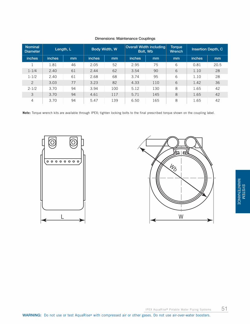
51IPEX AquaRise® Potable Water Piping Systems
SY
STE
MM
AIN
TEN
AN
CE
WARNING: Do not use or test AquaRise® with compressed air or other gases. Do not use air-over-water boosters.
Wb
WL
Nominal Diameter
Length, L Body Width, WOverall Width including
Bolt, WbTorqueWrench
Insertion Depth, C
inches inches mm inches mm inches mm mm inches mm
1 1.81 46 2.05 52 2.95 75 6 0.81 20.5
1-1/4 2.40 61 2.44 62 3.54 90 6 1.10 28
1-1/2 2.40 61 2.68 68 3.74 95 6 1.10 28
2 3.03 77 3.23 82 4.33 110 6 1.42 36
2-1/2 3.70 94 3.94 100 5.12 130 8 1.65 42
3 3.70 94 4.61 117 5.71 145 8 1.65 42
4 3.70 94 5.47 139 6.50 165 8 1.65 42
Dimensions: Maintenance Couplings
Note: Torque wrench kits are available through IPEX; tighten locking bolts to the final prescribed torque shown on the coupling label.

52
SY
STE
MM
AIN
TEN
AN
CE
IPEX AquaRise® Potable Water Piping Systems
WARNING: Do not use or test AquaRise® with compressed air or other gases. Do not use air-over-water boosters.
• Cut pipe squarely
• Remove all sharp edges and burrs on the inner and outeredges of the pipe end with sandpaper
• Clean the pipe surface of all impurities and dirt
• Pipe ends must be clean and free of dirt to ensure a properseal
• Ensure proper gap between pipe ends. See chart below fordetails
• Centre coupling over the gap between pipe ends
• Mark each pipe end to indicate the outer edge of thecoupling
STEP 3: INSTALL THE COUPLING• Fit the coupling over the pipe ends
• Ensure coupling is aligned with marks on pipe ends
STEP 4: TIGHTEN LOCKING BOLTS• Using a torque wrench, tighten locking bolts lightly and
alternately
• Ensure torque wrench is set to the proper torque levelshown on the coupling label
• Do not rotate coupling on the pipe joint once teeth areengaged
• Tighten locking bolts with a torque wrench to the finalprescribed torque shown on the coupling label
• Ensure the prescribed bolt torque is achieved (printed onthe coupling)
• Never exceed the prescribed bolt torque
STEP 5: SUPPORT COUPLINGS• Always maintain straight alignment of pipe and coupling
• For horizontal installations install recommended pipesupports 2" beyond each side of coupling
STEP 1: PREPARE AQUARISE PIPE
Pipe Pipe Gap
1" – 2" 0.2" 5 mm
2-1/2" – 4" 0.4" 10 mm
2" 2"
Insertion Depth, C (see chart on page 51)
Pipe Gap�
� �
�
STEP 2: PROPERLY FIT THE COUPLING
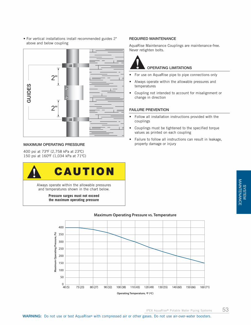
53IPEX AquaRise® Potable Water Piping Systems
SY
STE
MM
AIN
TEN
AN
CE
WARNING: Do not use or test AquaRise® with compressed air or other gases. Do not use air-over-water boosters.
Maximum Operating Pressure vs. Temperature
Operating Temperature, ºF (ºC)
40 (5)0
50
100
150
200
250
300
350
400
73 (23) 80 (27) 90 (32) 100 (38) 110 (43) 120 (49) 130 (55) 140 (60) 150 (66) 160 (71)
Max
imum
Ope
ratin
g Pr
essu
re, P
si
2"
2"
Always operate within the allowable pressures and temperatures shown in the chart below.
Pressure surges must not exceed the maximum operating pressure
OPERATING LIMITATIONS
• For use on AquaRise pipe to pipe connections only
• Always operate within the allowable pressures and temperatures
• Coupling not intended to account for misalignment or change in direction
FAILURE PREVENTION
• Follow all installation instructions provided with the couplings
• Couplings must be tightened to the specified torque values as printed on each coupling
• Failure to follow all instructions can result in leakage, property damage or injury
GU
IDE
S
CAUTION
MAXIMUM OPERATING PRESSURE
400 psi at 73ºF (2,758 kPa at 23ºC)150 psi at 160ºF (1,034 kPa at 71ºC)
• For vertical installations install recommended guides 2"above and below coupling
REQUIRED MAINTENANCE
AquaRise Maintenance Couplings are maintenance-free. Never retighten bolts.

54 IPEX AquaRise® Potable Water Piping Systems
WARNING: Do not use or test AquaRise® with compressed air or other gases. Do not use air-over-water boosters.
DISASSEMBLY
• Loosen bolts alternately but do not remove completely
• Do not rotate pipe joint on pipe as long as teeth are engaged
• If necessary, loosen teeth engagement.
• Insert tool underneath casing and lift.
SAFETY MEASURES BEFORE REMOVING THE MAINTENANCE COUPLING
• Ensure system is not pressurized
• Drain piping system
• Protect yourself and surroundings against spilling water
• Make sure the maintenance coupling is not supporting the pipe ends
DO NOT HARM RUBBER SEALING SURFACE
• Turn and move coupling smoothly
• Slide coupling beyond pipe joint
• Check rubber seal for any signs of damage
• Clean pipe joint
• Replace damaged coupling with a new coupling
• Reassemble according to instructions
CAUTION
NOTICE
SY
STE
MM
AIN
TEN
AN
CE

SECTION 5: SPECIFICATIONS
55IPEX AquaRise® Potable Water Piping Systems
SP
EC
IFICATIO
NS
WARNING: Do not use or test AquaRise® with compressed air or other gases. Do not use air-over-water boosters.
GENERAL REQUIREMENTS
(a) AquaRise is a thermoplastic piping system to be used inhot or cold potable water distribution systems only.
(b) Operating temperature for AquaRise shall not exceed160°F (71°C).
(c) Installation practices shall conform to manufacturers’guidelines.
(d) Installers shall consult with IPEX to resolve anyuncertainties before proceeding with installation.
(e) Pipe and molded fittings (couplings, tees, elbows,bushings and caps) are third-party certified toCSA B137.6, made to Iron Pipe Size (IPS) OutsideDiameter with a wall thickness of SDR 11 (StandardDimension Ratio).
(f) Cold water pressure rating of pipe and fittings with onlysolvent welded joints, Threaded Adapter Fittings, FullPressure Flange Kits and Maintenance Couplings shallbe 400 psi at 73°F (2,758 kPa at 23°C).
(g) AquaRise True Union Ball Valves in nominal sizes 1/2" through 2" are rated to 232 psi at 73°F (1,600 kPa at 23°C).
(h) AquaRise Flanges and unions are rated to 150 psi at73°F (1,034 kPa at 23°C).
(i) All of the above pressure ratings shall be reduced atelevated temperatures. The maximum AquaRiseoperating temperature must not exceed 160°F (71°C).
(j) All solvent weld joints shall be made in nominal pipesizes 1/2" through 2" using AquaRise One-Step Cement.For sizes 2-1/2" through 4", AquaRise Two-Step Cementshall be used in conjunction with AquaRise Primer.Specific usage instructions can be found in this manualand on the container labels. No alternatives shall beaccepted.
BUILDING CODE REQUIREMENTS
(a) AquaRise pipe and fittings shall be listed to ULCS102.2 to exhibit a Flame Spread Valu e (FSV) of notgreater than 25 and a Smoke Developed Value (SDV) ofnot greater than 50.
(b) The above listing shall be achieved without the use ofexternal pipe insulation or filling of the line with waterduring testing.
(c) All penetrations of fire-rated separations (i.e. ceilingsand wall) shall be sealed with a fire stop device orsystem which has been listed for use with AquaRise forthe specific substrate being penetrated. Fire stoplistings shall be tested in accordance with ULC S115and shall include a 50 Pa pressure differential in thetest assembly where required by local building codes.
(d) Refer to local building code requirements and the localAuthority Having Jurisdiction for the suitability ofAquaRise within Vertical Service Spaces.
(e) AquaRise may be used in all areas of buildingsclassified as Combustible Construction and in mostareas of Noncombustible Buildings includingPlenums(Sec. 3.6.4.3) and in High BuildingConstruction (Sec. 3.2.6).

LIM
ITE
D W
AR
RA
NTY
,LI
MIT
ATIO
N O
F LI
AB
ILTY
56 IPEX AquaRise® Potable Water Piping Systems
WARNING: Do not use or test AquaRise® with compressed air or other gases. Do not use air-over-water boosters.
SECTION 6: AQUARISE® SPECIFIC TERMS AND CONDITIONS OFSALE AND LIMITED WARRANTY AND LIMITATION OF LIABILITY
1. ScopeAll sales of AquaRise® products are subject to these product-specific terms and conditions (“Specific T&C’s”), as posted onthe Vendor’s website at the time of sale. Purchaser’s order isaccepted subject to these Specific T&C’s and to any terms andconditions agreed to in writing by the Vendor and Purchaser. Itis expressly agreed that any terms and conditions contained inthe Purchaser’s order or otherwise stipulated will be deemedfor the Purchaser’s internal use only and will not be binding onthe Vendor.
2. OrdersPurchaser’s orders are conditional upon satisfactory creditapproval by the Vendor. The Vendor will only accept orders inexcess of $100 before taxes or such greater amount as may bespecified for certain products. Once confirmed by the Vendor,orders for custom-made products manufactured to thePurchaser’s specifications and orders for large quantities of non-inventoried products cannot be cancelled, modified or returned,except with the Vendor’s written consent and upon terms whichprovide for indemnification of the Vendor for the costs andexpenses incurred.
3. ShipmentsDelivery schedules stipulated in either the quotation(“Quotation”) or the order confirmation (“Order Confirmation”)are approximate only and shipment will be made withinreasonable proximity thereto. Under no circumstances will theVendor be responsible for any damage whatsoever caused bydelays in shipment, whether resulting from causes within orbeyond the control of the Vendor. All shipments are F.O.B. theVendor’s location per the American standard sales terminology orEx Works per the Incoterms international rules applied to foreigntrade contracts. The Vendor shall bear no liability for Products lostor damaged during transit. The Vendor may agree to differentshipment terms as specified in the Quotation or in the OrderConfirmation. Freight prepaid orders, when applicable, will bedelivered by the carrier of the Vendor’s selection, unless the useof other carriers is agreed to in writing with the Purchaser.Purchaser must verify quantities and report discrepancies within2 business days of receipt.
4. PricesAll prices quoted or published are F.O.B. the Vendor’s location orEx Works. Published prices are subject to change without noticeuntil orders are accepted by the issuance of an OrderConfirmation, whereupon prices will remain firm for thoseshipments that take place within the 30-day period following thedate of the Order Confirmation. For specific projects, contracts orQuotations, the Vendor may agree in writing to protect prices foran extended period of time. Each order may be shipped in wholeor in part at the Vendor’s discretion. Each shipment made will beimmediately invoiced. Quoted or published prices do not includeany sales, use, excise or any other tax or levy imposed by anypresent or future law, regulation or other order, on any of theProducts. The Purchaser must provide the Vendor with taxexemption certificates or other documents, as required by thespecific tax jurisdiction, in order not to be charged for any of theapplicable taxes.
5. Terms of PaymentUnless other terms of payment are agreed to in writing by theVendor, payment is due upon delivery of the Products. Ifapplicable, cash discounts, expressed as a percentage, arecalculated on the net invoiced prices before any taxes, freight orother charges and can only be deducted from payment if the
Vendor receives payment from Purchaser on or prior to the duedate. Net 30 days means that payment is due within 30 days ofthe date of invoice and no cash discount is applicable. Overdueaccounts shall bear interest at a rate of 18% per annum. Thegranting of credit by the Vendor is at all times based on itsevaluation of the Purchaser’s financial condition. If such financialcondition does not justify continuance of shipment on credit, theVendor may require full or partial payment in advance.
6. Title to the Goods SoldThe Purchaser acknowledges and agrees that so long as theProducts are in Vendor’s possession, title to the Products shallremain with the Vendor until full payment therefore is received bythe Vendor. The Purchaser agrees to defend, indemnify and savethe Vendor harmless from any and all costs, expenses anddamages arising out of any claims asserted against the Vendorpursuant to the exercise of its ownership rights or any recourse inpayment of purchase price.
7. Return of ProductsThe Vendor may accept the return of Products, subject to thefollowing: a) prior to returning any Products, the Purchaser mustobtain a Return Material Authorization (RMA) number from theVendor, b) Products must be returned freight prepaid, unlessotherwise authorized by the Vendor and c) Products must bereceived in good saleable condition and, if required, in full cartonquantities and in their original packaging. A minimum returncharge of 25% of the purchase price will be applied against anycredit issued pursuant to the return of Products, except in thecase of a Vendor shipping error. The Vendor may apply additionalcharges against the credit to cover remarketing costs or mayrefuse to issue any credit, but will advise the Purchaseraccordingly. Certain Products, such as pressure pipe, custom-made configurations, obsolete products, excessive quantities orother specialty products cannot be returned. The Vendor maydirect that Products be destroyed for credit rather than returned.
8. Changes to ProductsThe Vendor reserves the right to make changes or improvementsto its Products without assuming any further obligation.
9. Patent RightsIf any claim is made against the Purchaser based on theallegation that any of the Products sold by the Vendor constitutean infringement of any U.S. or Canadian patent, the Purchasershall notify the Vendor immediately. The Vendor shall have theright, at its own option and expenses, to take any actions toprotect and defend its rights.
10. Force MajeureThe Vendor shall in no event be responsible or liable for any non-performance or delay in performance hereunder or any loss ordamage of any kind or nature whatsoever, direct or indirect,suffered by the Purchaser, subsequent purchasers, ultimate usersof the goods or any other person, as a result of any causes beyondthe reasonable control of the Vendor including, without limitation,price alterations, delay in shipments, strikes, lock-outs, fires,floods, civil commotion, riots, wars, acts of God, embargos, laborshortages, walk-outs, work slowdowns, accidents, breakdowns,delays in manufacture, transportation or delivery of goods ormaterials, shortages of materials or supplies, government acts orregulations or licensing action.
11. Governing LawThis agreement and all rights and obligations hereunder shall begoverned by the laws of the province of Ontario.

57IPEX AquaRise® Potable Water Piping Systems
LIMITE
D W
AR
RA
NTY,
LIMITATIO
N O
F LIAB
ILTY
WARNING: Do not use or test AquaRise® with compressed air or other gases. Do not use air-over-water boosters.
12. Non-waiverNo delay, failure, change or waiver by the Vendor to exercise anyone or more of these terms and conditions of sale shall beconstrued or shall operate to be a waiver thereof or a continuingwaiver of such terms and conditions.
13. Warranty and Limitation of Liability13.1 The Vendor warrants that its AquaRise products are, at the
time of their sale by Vendor, free from defects resultingfrom Vendor’s faulty manufacturing.
13.2 THERE IS NO WARRANTY, CONDITION ORREPRESENTATION OF ANY NATURE WHATSOEVER,EXPRESSED OR IMPLIED, BY STATUTE OROTHERWISE, EXCEPT AS HEREIN CONTAINED. ANYIMPLIED WARRANTIES OF MERCHANTABILITYAND/OR FITNESS OF THE PRODUCTS FOR A SPECIALPURPOSE AND ANY OTHER WARRANTY OF QUALITYARE EXPRESSLY DISCLAIMED.
13.3 The Vendor will replace, free of charge, includingshipping charges at the original point of delivery, anyProduct which is found to breach this limited warranty.Any such defective Product will be replaced with aProduct of the same type and size as the defectiveProduct.
13.4 THIS LIMITED WARRANTY IS VALID ONLY FOR THEPERIOD OF 10 YEARS FROM THE DATE OF THE SALEOF THE PRODUCT ALLEGED TO BE DEFECTIVE BYVENDOR AND WILL ONLY APPLY IF ALL OF THEFOLLOWING CONDITIONS ARE MET:
13.4.1 The Product must have been used only in applicationsand under conditions (handling, installation, testing,use, water temperature, maintenance, repairs, etc.)that are strictly in compliance with the AquaRiseTechnical Manual currently available from the Vendorat the time of installation. The AquaRise system hasspecifically designed pipe, fittings, valves and sealantsand is designed for operation using only genuineAquaRise products. The use of any non-AquaRiseCPVC components within an AquaRise system isprohibited, voiding the warranty for the affectedsystem, unless approved by IPEX in writing prior toinstallation.
13.4.2 The defect must not be due to faulty installation,misalignment of Products, vibration, ordinary wear andtear, corrosion, erosion, U.V. degradation, incompatiblelubricants, pastes and thread sealants, unusualpressure surges or pulsation, water hammer,temperature shocking, or fouling.
13.4.3 The Product must have been installed in good andworkmanlike manner consistent with the Vendor’slatest published instructions and with the state of theart industry standards and plumbing practices, and inconformance with all applicable laws and regulations.
13.4.4 The Product must have not been altered or modifiedafter leaving the Vendor’s premises, and must havebeen used in no more than one installation, show noevidence of disassembly or tampering, and have notbeen subjected to abnormal operating conditions,accident, abuse, misuse, unauthorized alteration, orrepair.
13.4.5 The Product must not have been subject to acts ofnature such as earthquakes, fire, flood, or lightning, orany other event of force majeure.
13.4.6 The Product must not have been subject to waterfreezing inside any of its components.
13.4.7 If the Product is perishable, the Product must havebeen used prior to the expiration date as indicated onthe Product.
13.4.8 The Claimant must notify the Vendor in writing withinten (10) days of when the defect was discovered, orshould have been discovered in the exercise of ordinarycare, and the defective Product must be promptlyreturned to the Vendor. Notice of a defective Productunder this limited warranty should be directed to yourlocal IPEX Customer Service representative. Claimantmust provide documentary evidence of failure, as wellas the failed components themselves or representativesamples of Product that is alleged to have failed, andmust agree to allow a meaningful and reasonableopportunity for Vendor to inspect the system in whichthe alleged defective Product was installed.
13.5 ANY LIABILITY IN RESPECT TO THE PRODUCTS ISSTRICTLY LIMITED TO THEIR REPLACEMENT ASHEREINBEFORE SPECIFIED AND THERE SHALL NOT,IN ANY EVENT, BE ANY LIABILITY FOR ANY LABOURCHARGES OR OTHER DAMAGES OR FOR ANY OTHERCLAIM FOR INCIDENTAL, CONSEQUENTIAL, SPECIALOR PUNITIVE DAMAGES.
13.6 Without limiting the generality of the foregoing, anyliability or responsibility is disclaimed:
13.6.1 for labor, materials, and/or other expenses required toreplace a defective Product;
13.6.2 for any damage to a person or property caused by adefective Product;
13.6.3 for expenses to repair any damage resulting from theuse of a defective Product;
13.6.4 for calculations, product drawings, or engineeringdesign specifications;
13.6.5 regarding the accuracy of any plans, drawings, orspecifications furnished to the purchaser as part of thesale of any of its products;
13.6.6 for loss or damage resulting from failure to abide bymanufacturer’s warnings, safety instructions, or otherprecautionary guidelines.
13.7 ANY CLAIM, WHETHER IN CONTRACT OR IN TORT(INCLUDING NEGLIGENCE) OR OTHERWISE, WITHRESPECT TO OR ARISING OUT OF THE SALE,DELIVERY, INSTALLATION, REPAIR OR USE OF ANYPRODUCTS SOLD TO BUYER SHALL NOT IN ANYEVENT EXCEED THE PURCHASE PRICE OF THEPRODUCTS FOUND TO BE DEFECTIVE. It is theresponsibility of the owner to obtain and pay foremergency repairs.
13.8 No statement, conduct, or description by the Vendor, itsaffiliate, its representative, its distributor or its agent, inaddition to or beyond this Limited Warranty, shallconstitute a warranty. This limited warranty may only bemodified in a writing signed by an officer of the Vendor.
13.9 ANY DISPUTE, CLAIM, OR CONTROVERSY ARISINGOUT OF OR RELATING TO THE TERMS OR EFFECT OFTHIS LIMITED WARRANTY SHALL BE RESOLVED BYBINDING ARBITRATION IN ACCORDANCE WITH THECOMMERCIAL ARBITRATION RULES OF ONTARIO.THIS ARBITRATION SHALL BE HELD IN TORONTO,ONTARIO. The obligation to arbitrate shall extend to anyaffiliate, subsidiary, officer, employee, shareholder,principal, agent, trustee in bankruptcy, or guarantor of aparty making or defending any claim hereunder.

58 IPEX AquaRise® Potable Water Piping Systems
WARNING: Do not use or test AquaRise® with compressed air or other gases. Do not use air-over-water boosters.
APPENDIXFor your convenience, additional copies of
Jobsite Notices are provided here to be cut outand posted at the jobsite.
If additional copies of any instructions are needed, or for any questions concerning the safe and proper installation of IPEX products, contact IPEX Toll Free (866) 473-9462
For the most up-to-date information on AquaRise products, visit: ipexaquarise.com
Always adhere to local jobsite and workplace safety regulations.

WARNING: Do not use or test AquaRise® with compressed air or other gases. Do not use air-over-water boosters.
<<< C
UT
& P
OS
T AT
JO
BS
ITE
>>>
Plea
se r
ead
the
follo
win
g no
tice
befo
re b
egin
ning
any
act
ivity
whi
ch c
ould
com
e in
con
tact
w
ith th
is s
yste
m:
Aqua
Rise
pip
ing
com
pone
nts
may
be
dam
aged
by
certa
in s
ubst
ance
s an
d co
nstru
ctio
n pr
actic
es.
DO N
OTst
ack,
sup
port
, ha
ng e
quip
men
t, o
r ha
ng f
lexi
ble
wire
/cab
le, es
peci
ally
com
mun
icat
ions
cab
le, or
oth
er m
ater
ial o
n th
e Aqu
aRis
e pi
ping
sys
tem
.
ONLY
syst
em c
ompa
tible
mat
eria
ls in
clud
ing,
but
not
lim
ited
to, so
lven
t ce
men
ts, ca
ulks
and
sea
lant
s, a
s no
ted
in t
heAqu
aRis
e Te
chni
cal M
anua
l, sh
ould
be
used
in c
onta
ct w
ith t
his
syst
em.
DO N
OTex
pose
Aqu
aRis
e pr
oduc
ts t
o in
com
patib
le s
ubst
ance
s, s
uch
as c
uttin
g oi
ls, no
n-w
ater
bas
ed p
aint
s, p
acki
ng o
ils(c
omm
only
fou
nd in
pum
ps), t
radi
tiona
l pip
e th
read
pas
te a
nd d
ope,
fun
gici
des,
ter
miti
cide
s, in
sect
icid
es, de
terg
ents
,bu
ildin
g ca
ulks
, ad
hesi
ves
tape
, so
lder
flu
x, f
lexi
ble
wire
/cab
le (
with
spe
cial
con
side
ratio
n fo
r co
mm
unic
atio
ns c
ablin
g),
and
non-
appr
oved
spr
ay f
oam
insu
latio
n m
ater
ials
.
DO N
OTex
pose
Aqu
aRis
e pr
oduc
ts t
o op
en f
lam
e, s
olde
r, an
d so
lder
ing
flux.
DO N
OTdr
op, di
stor
t, o
r im
pact
Aqu
aRis
e pr
oduc
ts o
r al
low
obj
ects
to
be d
ropp
ed o
n th
em.
DO N
OTha
ndle
Aqu
aRis
e pr
oduc
ts w
ith g
love
s co
ntam
inat
ed w
ith o
ils (
hydr
ocar
bons
) or
oth
er in
com
patib
le m
ater
ials
.
Failu
re to
follo
w th
is n
otic
e m
ay c
ause
cra
cks
or fr
actu
res
to d
evel
op in
Aqu
aRis
e pr
oduc
ts
resu
lting
in p
erso
nal i
njur
y an
d pr
oper
ty d
amag
e du
e to
leak
s or
floo
ding
. The
pre
senc
e of
any
visi
ble
crac
ks m
ay r
equi
re p
artia
l or
full
syst
em r
epla
cem
ent.
For
addi
tiona
l inf
orm
atio
n co
ntac
t th
e ge
nera
l con
tract
or o
r sy
stem
inst
alle
r.
FOR
ADDI
TION
AL A
QUAR
ISE
PROD
UCT
IN
FORM
ATIO
N,
CON
TACT
“IP
EX”
AT 8
66-4
73-9
462
OR V
ISIT
IPE
XAQU
ARIS
E.CO
M
Pot
able
Wat
er P
ipin
g Sys
tem
s(C
olou
red
Teal
Blu
e)
NOTIC
E
WARNING: Do not use or test AquaRise® with compressed air or other gases. Do not use air-over-water boosters.
If additional copies of any instructions are needed, or for any questions concerning the safe and proper installation of IPEX products,
contact IPEX Toll Free (866) 473-9462 For the most up-to-date information on AquaRise products,
visit: ipexaquarise.com
Always adhere to local jobsite and workplace safety regulations.

WARNING: Do not use or test AquaRise® with compressed air or other gases. Do not use air-over-water boosters.
<<< C
UT
& P
OS
T AT
JO
BS
ITE
>>>
Plea
se r
ead
the
follo
win
g no
tice
befo
re b
egin
ning
any
act
ivity
whi
ch c
ould
com
e in
con
tact
w
ith th
is s
yste
m:
Aqua
Rise
pip
ing
com
pone
nts
may
be
dam
aged
by
certa
in s
ubst
ance
s an
d co
nstru
ctio
n pr
actic
es.
DO N
OTst
ack,
sup
port
, ha
ng e
quip
men
t, o
r ha
ng f
lexi
ble
wire
/cab
le, es
peci
ally
com
mun
icat
ions
cab
le, or
oth
er m
ater
ial o
n th
e Aqu
aRis
e pi
ping
sys
tem
.
ONLY
syst
em c
ompa
tible
mat
eria
ls in
clud
ing,
but
not
lim
ited
to, so
lven
t ce
men
ts, ca
ulks
and
sea
lant
s, a
s no
ted
in t
heAqu
aRis
e Te
chni
cal M
anua
l, sh
ould
be
used
in c
onta
ct w
ith t
his
syst
em.
DO N
OTex
pose
Aqu
aRis
e pr
oduc
ts t
o in
com
patib
le s
ubst
ance
s, s
uch
as c
uttin
g oi
ls, no
n-w
ater
bas
ed p
aint
s, p
acki
ng o
ils(c
omm
only
fou
nd in
pum
ps), t
radi
tiona
l pip
e th
read
pas
te a
nd d
ope,
fun
gici
des,
ter
miti
cide
s, in
sect
icid
es, de
terg
ents
,bu
ildin
g ca
ulks
, ad
hesi
ves
tape
, so
lder
flu
x, f
lexi
ble
wire
/cab
le (
with
spe
cial
con
side
ratio
n fo
r co
mm
unic
atio
ns c
ablin
g),
and
non-
appr
oved
spr
ay f
oam
insu
latio
n m
ater
ials
.
DO N
OTex
pose
Aqu
aRis
e pr
oduc
ts t
o op
en f
lam
e, s
olde
r, an
d so
lder
ing
flux.
DO N
OTdr
op, di
stor
t, o
r im
pact
Aqu
aRis
e pr
oduc
ts o
r al
low
obj
ects
to
be d
ropp
ed o
n th
em.
DO N
OTha
ndle
Aqu
aRis
e pr
oduc
ts w
ith g
love
s co
ntam
inat
ed w
ith o
ils (
hydr
ocar
bons
) or
oth
er in
com
patib
le m
ater
ials
.
Failu
re to
follo
w th
is n
otic
e m
ay c
ause
cra
cks
or fr
actu
res
to d
evel
op in
Aqu
aRis
e pr
oduc
ts
resu
lting
in p
erso
nal i
njur
y an
d pr
oper
ty d
amag
e du
e to
leak
s or
floo
ding
. The
pre
senc
e of
any
visi
ble
crac
ks m
ay r
equi
re p
artia
l or
full
syst
em r
epla
cem
ent.
For
addi
tiona
l inf
orm
atio
n co
ntac
t th
e ge
nera
l con
tract
or o
r sy
stem
inst
alle
r.
FOR
ADDI
TION
AL A
QUAR
ISE
PROD
UCT
IN
FORM
ATIO
N,
CON
TACT
“IP
EX”
AT 8
66-4
73-9
462
OR V
ISIT
IPE
XAQU
ARIS
E.CO
M
Pot
able
Wat
er P
ipin
g Sys
tem
s(C
olou
red
Teal
Blu
e)
NOTIC
E

WARNING: Do not use or test AquaRise® with compressed air or other gases. Do not use air-over-water boosters.
If additional copies of any instructions are needed, or for any questions concerning the safe and proper installation of IPEX products,
contact IPEX Toll Free (866) 473-9462 For the most up-to-date information on AquaRise products,
visit: ipexaquarise.com
Always adhere to local jobsite and workplace safety regulations.

IPEX AquaRise® Potable Water Piping Systems
WARNING: Do not use or test AquaRise® with compressed air or other gases. Do not use air-over-water boosters.
<<< C
UT
& P
OS
T AT
JO
BS
ITE
>>>
Plea
se r
ead
the
follo
win
g no
tice
befo
re b
egin
ning
any
act
ivity
whi
ch c
ould
com
e in
con
tact
w
ith th
is s
yste
m:
Aqua
Rise
pip
ing
com
pone
nts
may
be
dam
aged
by
certa
in s
ubst
ance
s an
d co
nstru
ctio
n pr
actic
es.
DO N
OTst
ack,
sup
port
, ha
ng e
quip
men
t, o
r ha
ng f
lexi
ble
wire
/cab
le, es
peci
ally
com
mun
icat
ions
cab
le, or
oth
er m
ater
ial o
n th
e Aqu
aRis
e pi
ping
sys
tem
.
ONLY
syst
em c
ompa
tible
mat
eria
ls in
clud
ing,
but
not
lim
ited
to, so
lven
t ce
men
ts, ca
ulks
and
sea
lant
s, a
s no
ted
in t
heAqu
aRis
e Te
chni
cal M
anua
l, sh
ould
be
used
in c
onta
ct w
ith t
his
syst
em.
DO N
OTex
pose
Aqu
aRis
e pr
oduc
ts t
o in
com
patib
le s
ubst
ance
s, s
uch
as c
uttin
g oi
ls, no
n-w
ater
bas
ed p
aint
s, p
acki
ng o
ils(c
omm
only
fou
nd in
pum
ps), t
radi
tiona
l pip
e th
read
pas
te a
nd d
ope,
fun
gici
des,
ter
miti
cide
s, in
sect
icid
es, de
terg
ents
,bu
ildin
g ca
ulks
, ad
hesi
ves
tape
, so
lder
flu
x, f
lexi
ble
wire
/cab
le (
with
spe
cial
con
side
ratio
n fo
r co
mm
unic
atio
ns c
ablin
g),
and
non-
appr
oved
spr
ay f
oam
insu
latio
n m
ater
ials
.
DO N
OTex
pose
Aqu
aRis
e pr
oduc
ts t
o op
en f
lam
e, s
olde
r, an
d so
lder
ing
flux.
DO N
OTdr
op, di
stor
t, o
r im
pact
Aqu
aRis
e pr
oduc
ts o
r al
low
obj
ects
to
be d
ropp
ed o
n th
em.
DO N
OTha
ndle
Aqu
aRis
e pr
oduc
ts w
ith g
love
s co
ntam
inat
ed w
ith o
ils (
hydr
ocar
bons
) or
oth
er in
com
patib
le m
ater
ials
.
Failu
re to
follo
w th
is n
otic
e m
ay c
ause
cra
cks
or fr
actu
res
to d
evel
op in
Aqu
aRis
e pr
oduc
ts
resu
lting
in p
erso
nal i
njur
y an
d pr
oper
ty d
amag
e du
e to
leak
s or
floo
ding
. The
pre
senc
e of
any
visi
ble
crac
ks m
ay r
equi
re p
artia
l or
full
syst
em r
epla
cem
ent.
For
addi
tiona
l inf
orm
atio
n co
ntac
t th
e ge
nera
l con
tract
or o
r sy
stem
inst
alle
r.
FOR
ADDI
TION
AL A
QUAR
ISE
PROD
UCT
IN
FORM
ATIO
N,
CON
TACT
“IP
EX”
AT 8
66-4
73-9
462
OR V
ISIT
IPE
XAQU
ARIS
E.CO
M
Pot
able
Wat
er P
ipin
g Sys
tem
s(C
olou
red
Teal
Blu
e)
NOTIC
E

WARNING: Do not use or test AquaRise® with compressed air or other gases. Do not use air-over-water boosters.
If additional copies of any instructions are needed, or for any questions concerning the safe and proper installation of IPEX products,
contact IPEX Toll Free (866) 473-9462 For the most up-to-date information on AquaRise products,
visit: ipexaquarise.com
Always adhere to local jobsite and workplace safety regulations.

WARNING: Do not use or test AquaRise® with compressed air or other gases. Do not use air-over-water boosters.
Plea
se r
ead
the
follo
win
g no
tice
befo
re b
egin
ning
any
act
ivity
whi
ch c
ould
com
e in
con
tact
w
ith th
is s
yste
m:
Aqua
Rise
pip
ing
com
pone
nts
may
be
dam
aged
by
certa
in s
ubst
ance
s an
d co
nstru
ctio
n pr
actic
es.
DO N
OTst
ack,
sup
port
, ha
ng e
quip
men
t, o
r ha
ng f
lexi
ble
wire
/cab
le, es
peci
ally
com
mun
icat
ions
cab
le, or
oth
er m
ater
ial o
n th
e Aqu
aRis
e pi
ping
sys
tem
.
ONLY
syst
em c
ompa
tible
mat
eria
ls in
clud
ing,
but
not
lim
ited
to, so
lven
t ce
men
ts, ca
ulks
and
sea
lant
s, a
s no
ted
in t
heAqu
aRis
e Te
chni
cal M
anua
l, sh
ould
be
used
in c
onta
ct w
ith t
his
syst
em.
DO N
OTex
pose
Aqu
aRis
e pr
oduc
ts t
o in
com
patib
le s
ubst
ance
s, s
uch
as c
uttin
g oi
ls, no
n-w
ater
bas
ed p
aint
s, p
acki
ng o
ils(c
omm
only
fou
nd in
pum
ps), t
radi
tiona
l pip
e th
read
pas
te a
nd d
ope,
fun
gici
des,
ter
miti
cide
s, in
sect
icid
es, de
terg
ents
,bu
ildin
g ca
ulks
, ad
hesi
ves
tape
, so
lder
flu
x, f
lexi
ble
wire
/cab
le (
with
spe
cial
con
side
ratio
n fo
r co
mm
unic
atio
ns c
ablin
g),
and
non-
appr
oved
spr
ay f
oam
insu
latio
n m
ater
ials
.
DO N
OTex
pose
Aqu
aRis
e pr
oduc
ts t
o op
en f
lam
e, s
olde
r, an
d so
lder
ing
flux.
DO N
OTdr
op, di
stor
t, o
r im
pact
Aqu
aRis
e pr
oduc
ts o
r al
low
obj
ects
to
be d
ropp
ed o
n th
em.
DO N
OTha
ndle
Aqu
aRis
e pr
oduc
ts w
ith g
love
s co
ntam
inat
ed w
ith o
ils (
hydr
ocar
bons
) or
oth
er in
com
patib
le m
ater
ials
.
Failu
re to
follo
w th
is n
otic
e m
ay c
ause
cra
cks
or fr
actu
res
to d
evel
op in
Aqu
aRis
e pr
oduc
ts
resu
lting
in p
erso
nal i
njur
y an
d pr
oper
ty d
amag
e du
e to
leak
s or
floo
ding
. The
pre
senc
e of
any
visi
ble
crac
ks m
ay r
equi
re p
artia
l or
full
syst
em r
epla
cem
ent.
For
addi
tiona
l inf
orm
atio
n co
ntac
t th
e ge
nera
l con
tract
or o
r sy
stem
inst
alle
r.
FOR
ADDI
TION
AL A
QUAR
ISE
PROD
UCT
IN
FORM
ATIO
N,
CON
TACT
“IP
EX”
AT 8
66-4
73-9
462
OR V
ISIT
IPE
XAQU
ARIS
E.CO
M
Pot
able
Wat
er P
ipin
g Sys
tem
s(C
olou
red
Teal
Blu
e)
NOTIC
E

If additional copies of any instructions are needed, or for any questions concerning the safe and proper installation of IPEX products,
contact IPEX Toll Free (866) 473-9462 For the most up-to-date information on AquaRise products,
visit: ipexaquarise.com
Always adhere to local jobsite and workplace safety regulations.
WARNING: Do not use or test AquaRise® with compressed air or other gases. Do not use air-over-water boosters.

MNMEARIP171002C © 2017 IPEX MS0036C
SALES AND CUSTOMER SERVICE
Customers call IPEX Inc.
Toll free: (866) 473-9462
ipexna.com
About the IPEX Group of Companies
As leading suppliers of thermoplastic piping systems, the IPEX Group of
Companies provides our customers with some of the largest and most
comprehensive product lines. All IPEX products are backed by more than
50 years of experience. With state-of-the-art manufacturing facilities and
distribution centers across North America, we have earned a reputation for
product innovation, quality, end-user focus and performance.
Markets served by IPEX group products are:
• Electrical
• Telecommunications and Utility
• Industrial Process Piping
• Municipal Pressure and Gravity Flow
• Plumbing, DWV and Water Supply
• Irrigation
• Electrofusion PE for Gas and Water
• Industrial, Plumbing and Electrical cements
• Fire Protection
• PVC, CPVC, PP, PVDF, PE, ABS, and PEX pipe and fittings
This literature is published in good faith and is believed to be reliable.However it does not represent and/or warrant in any manner theinformation and suggestions contained in this brochure. Data presented isthe result of laboratory tests and field experience.
A policy of ongoing product improvement is maintained. This may result inmodifications of features and/or specifications without notice.
AquaRise® and the colour of the AquaRise® pipes and fittings are
registered trademarks.
Distributed in Canada by IPEX Inc., Mississauga, Ontario.