Embed Size (px)
Citation preview

Voltage Backfeed on Distribution LinesTerry MayoOncor
2
Background
A thunderstorm with high winds, lightning and rain caused two phases of a three-phase distribution primary lateral to blow together at a slack span location causing the A or B (unknown phase) and C phase lateral fuses to open leaving the lateral energized by only one phase.
A residential subdivision customer served by C phase on this lateral called in and reported “dimly glowing” lights.
Outage restoration personnel went to the residence and measured approximately 27V (23% of nominal voltage) at the meter base.
The voltage was high enough to cause the filaments in the incandescent light bulbs in a ceiling fan to dimly glow. The ceiling fan motor was attempting to turn.
The customer was concerned about potential damage to appliances from low voltage.
This prompted an investigation into the source of the voltage backfeedcondition.
3
Potential Sources of Voltage Backfeed On A Distribution Circuit
Emergency generators – residential or commercial customers
Distributed generation – photovoltaic systems or wind turbines
Inadvertent interconnections with street light circuits
Transformer banks connected in delta configuration
Padmount transformers – delta and wye winding configurations
4
Distribution Circuit Configuration
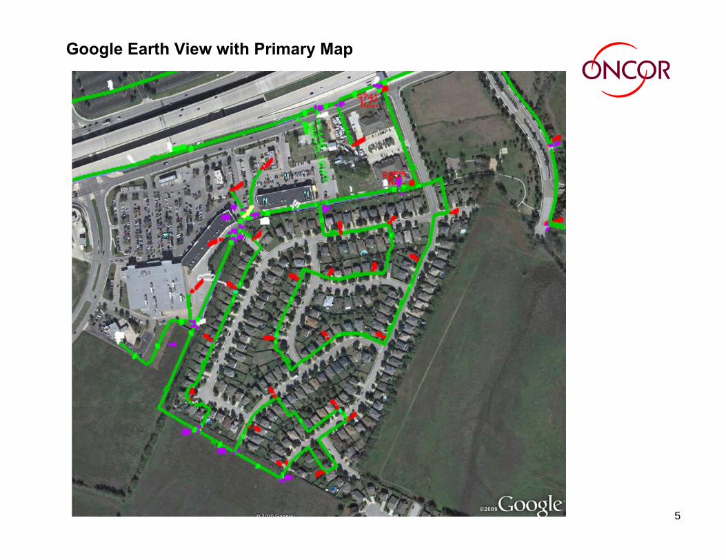
This is a typical distribution circuit in an urban setting where both a commercial strip center and a residential subdivision are served from the same three-phase lateral.
The distribution primary voltage is 14,400V phase-to-neutral and 24,940V phase-to-phase.
The lateral circuit is protected by 3 – 100 A fuses.
5
Google Earth View with Primary Map
6
Electrical load
The commercial customers are served using 4 three-phase padmounttransformers and 3 banks of single-phase transformers connected to the lateral circuit. All the transformations are wye-wye. The transformer sizes are shown below:4 padmount wye-wye transformers
1000 kVA, 500 kVA, 225 kVA, 150 kVA
3 single-phase overhead transformers banked in wye-wyeconfiguration3 - 75 kVA, 3 - 37 kVA, 3 - 25 kVA
The customer served by the 1000 kVA transformer has 300 kVAR of power factor correction capacitors that are connected phase-to-phase. This customer also has 922 kVA of delta connected dry type transformers. Other commercial customers also have delta connected dry type transformers.
The residential subdivision customers are served by three single-phase underground loops that were all on C phase. The load has since been balanced across all three phases. This load is connected phase-to-neutral.

7
Wye-Wye Transformer Bank using 3 Single-Phase Transformers – B & C Phases Open
V A-G = 100% of Nominal Voltage
V B-G = OPEN
V C-G = OPEN
V b-g = 0
V c-g = 0
V a-g = 100% of Nominal Voltage
8
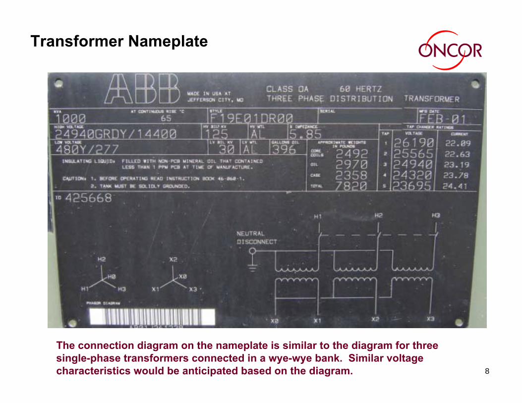
Transformer Nameplate
The connection diagram on the nameplate is similar to the diagram for three single-phase transformers connected in a wye-wye bank. Similar voltage characteristics would be anticipated based on the diagram.

9
Padmount Transformer Design
Oncor’s three-phase padmount transformer purchasing specification requires 4 or 5 legged core design in order to reduce the probability of tank heating when zero-sequence voltage is applied.
All the padmount transformers involved in this case study were 5 legged core construction.
The result of a phase loss is not intuitive. The results of a phase loss depend on which phase is lost.
This transformer design will allow voltage to backfeed from the energized phase to the open phases.
[4]

10
ABB Transformer Voltage Measurements
ABB agreed to assist with transformer voltage measurements under various loss of phase scenarios.
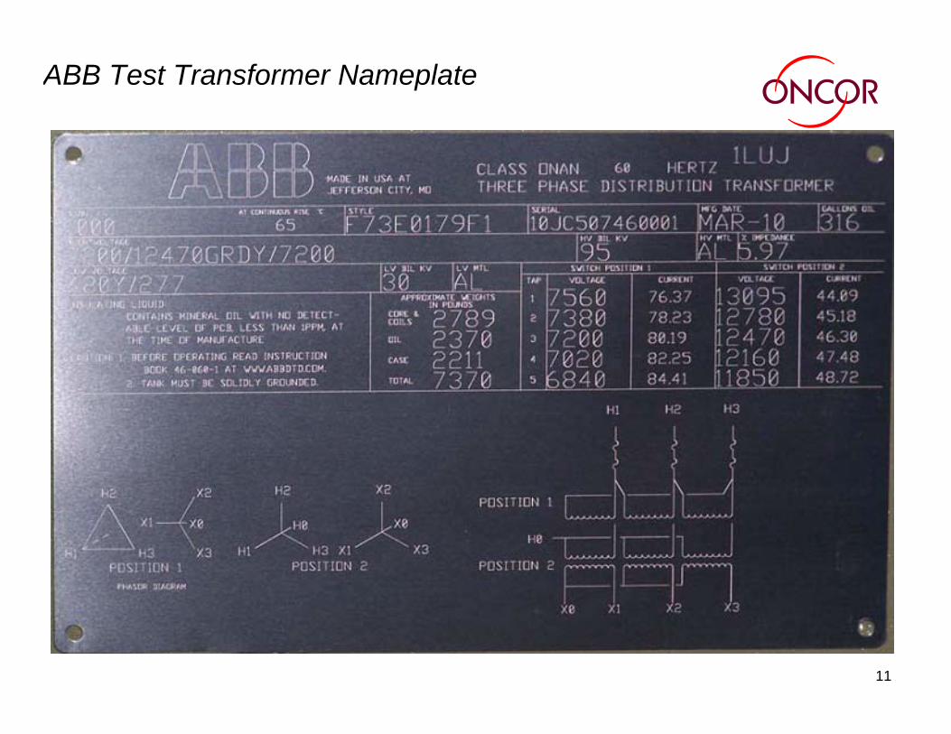
ABB Jefferson City performed voltage measurements on the transformer secondary terminals while simulating the range of open primary phase conditions in their local test booth. These tests were performed on serial 10J434104 (JC507460001) (Style F73E0179F) on March 4th 2010.
Transformer Information
The transformer under test was a 7200/12470GRDY/7200 (HV) and was a 480 Y/277 (LV). The transformer has a delta-wye switch.
The design and construction of this transformer is similar to transformers used in the Oncor system.
11
ABB Test Transformer Nameplate

12
ABB Transformer Voltage Measurement Setup
13
ABB Voltage Measurement Testing Procedure
The testing was performed by energizing the transformer from the high side with full rated voltage and the voltage was measured on the low side.
Different scenarios of voltage loss on the the high side was tested.
The test was performed on Wye HV position and was repeated on Delta HV position.
The test was performed on nominal tap (Tap Position 3).
14
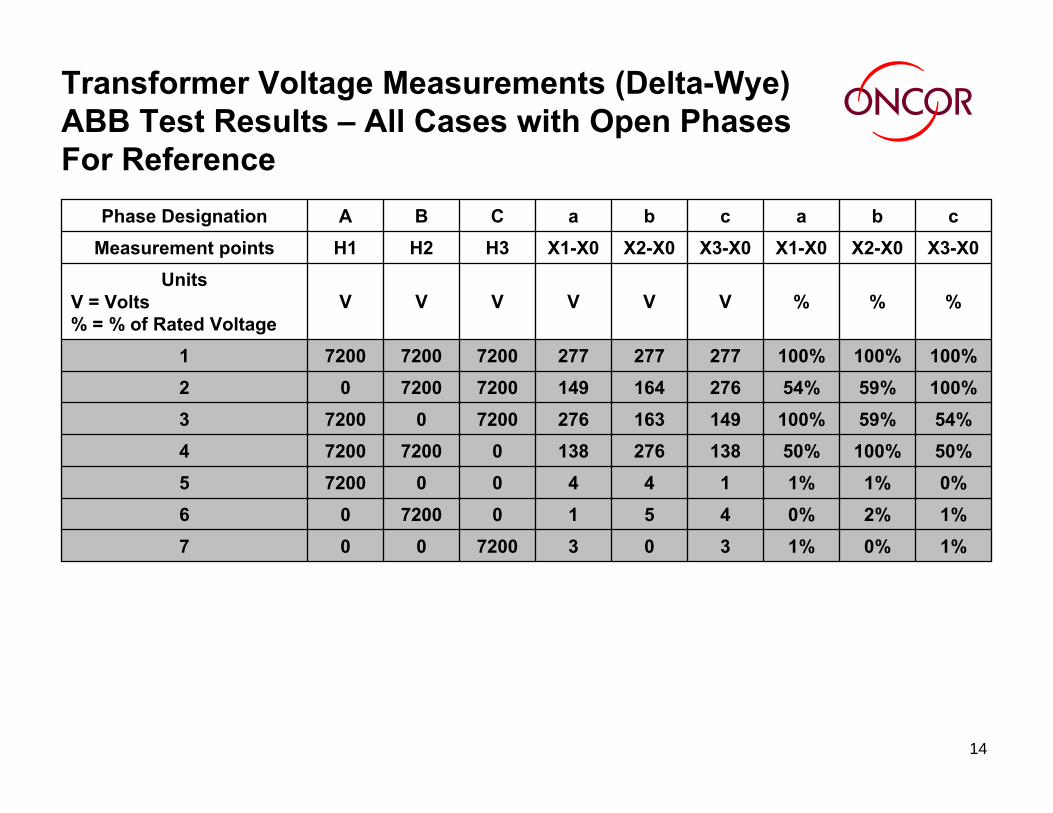
Transformer Voltage Measurements (Delta-Wye) ABB Test Results – All Cases with Open Phases For Reference
1%0%1%30372000071%2%0%45107200060%1%1%144007200550%100%50%138276138072007200454%59%100%1491632767200072003
100%59%54%2761641497200720002100%100%100%2772772777200720072001
%%%VVVVVVUnits
V = Volts% = % of Rated Voltage
X3-X0X2-X0X1-X0X3-X0X2-X0X1-X0H3H2H1Measurement pointscbacbaCBAPhase Designation

15
Transformer Voltage Measurements (Wye-Wye) ABB Test Results – Open Primary Phases No Load Connected On Secondary
99%48%20%275132567200007
51%99%51%1412741410720006
25%47%99%681312750072005
66%99%100%1832752770720072004
100%53%100%2771472767200072003
100%99%66%2772751837200720002
101%99%100%2792742777200720072001
%%%VVVVVVUnits
V = Volts% = % of Rated Voltage
X3-X0X2-X0X1-X0X3-X0X2-X0X1-X0H3-H0H2-H0H1-H0Measurement pointscbacbaCBAPhase Designation
16
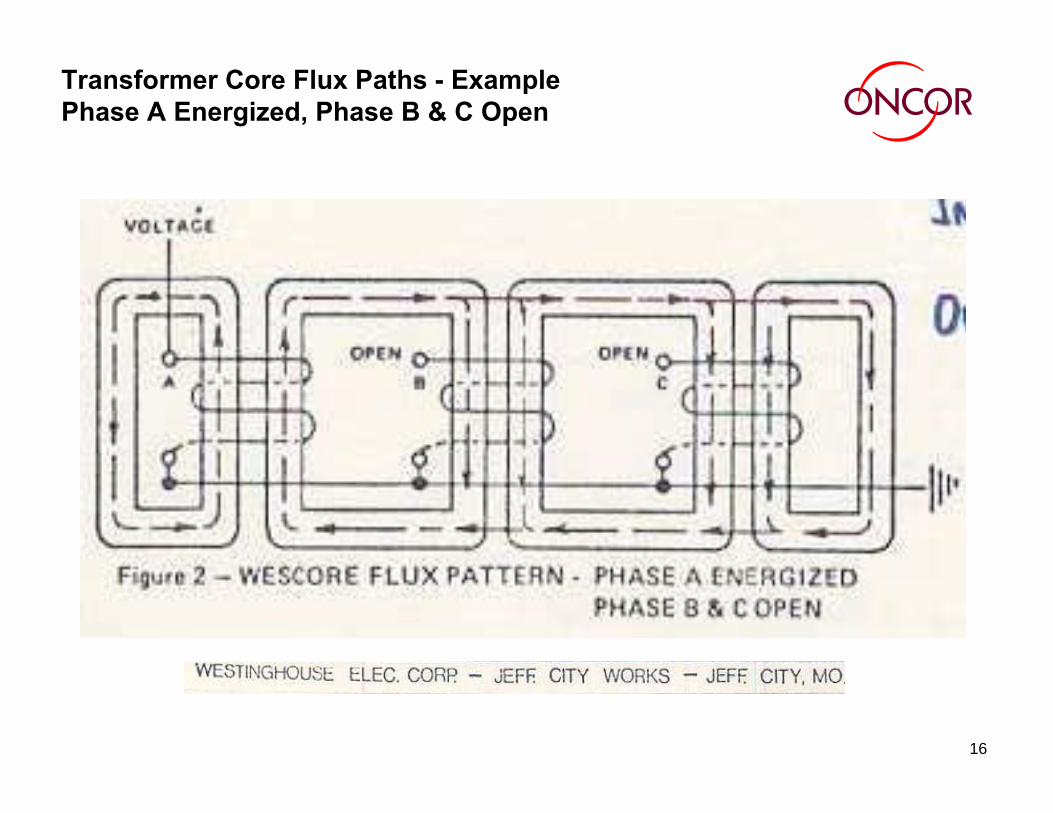
Transformer Core Flux Paths - Example Phase A Energized, Phase B & C Open
17
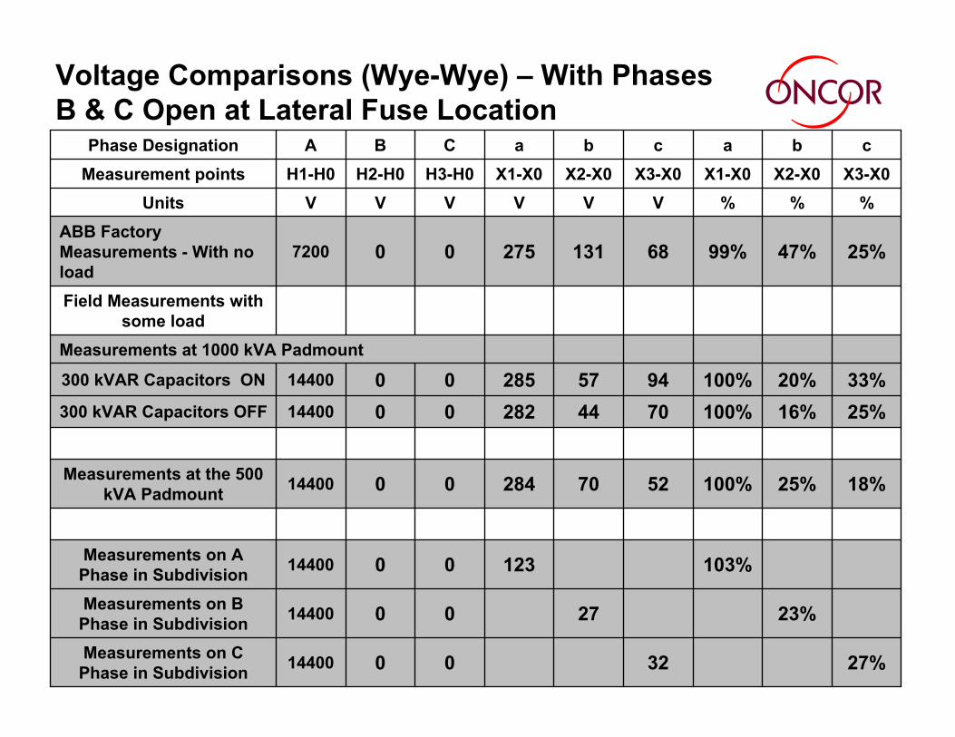
Voltage Comparisons (Wye-Wye) – With Phases B & C Open at Lateral Fuse Location
27%320014400Measurements on C Phase in Subdivision
23%270014400Measurements on B Phase in Subdivision
103%1230014400Measurements on A Phase in Subdivision
18%25%100%52702840014400Measurements at the 500 kVA Padmount
25%16%100%70442820014400300 kVAR Capacitors OFF
33%20%100%94572850014400300 kVAR Capacitors ON
Measurements at 1000 kVA Padmount
Field Measurements with some load
25%47%99%68131275007200ABB Factory Measurements - With no load
%%%VVVVVVUnitsX3-X0X2-X0X1-X0X3-X0X2-X0X1-X0H3-H0H2-H0H1-H0Measurement points
cbacbaCBAPhase Designation
18
Effect of Phase-To-Neutral Load on Excitation Voltage on Open PhasesThe amount of phase-to-neutral load present on the phases influences
the voltage levels on the corresponding open phases of the transformer.
The comparison of voltage measurements in the ABB results to the field measurements indicate that more phase-to-neutral load will further reduce the open phase voltage levels.

19
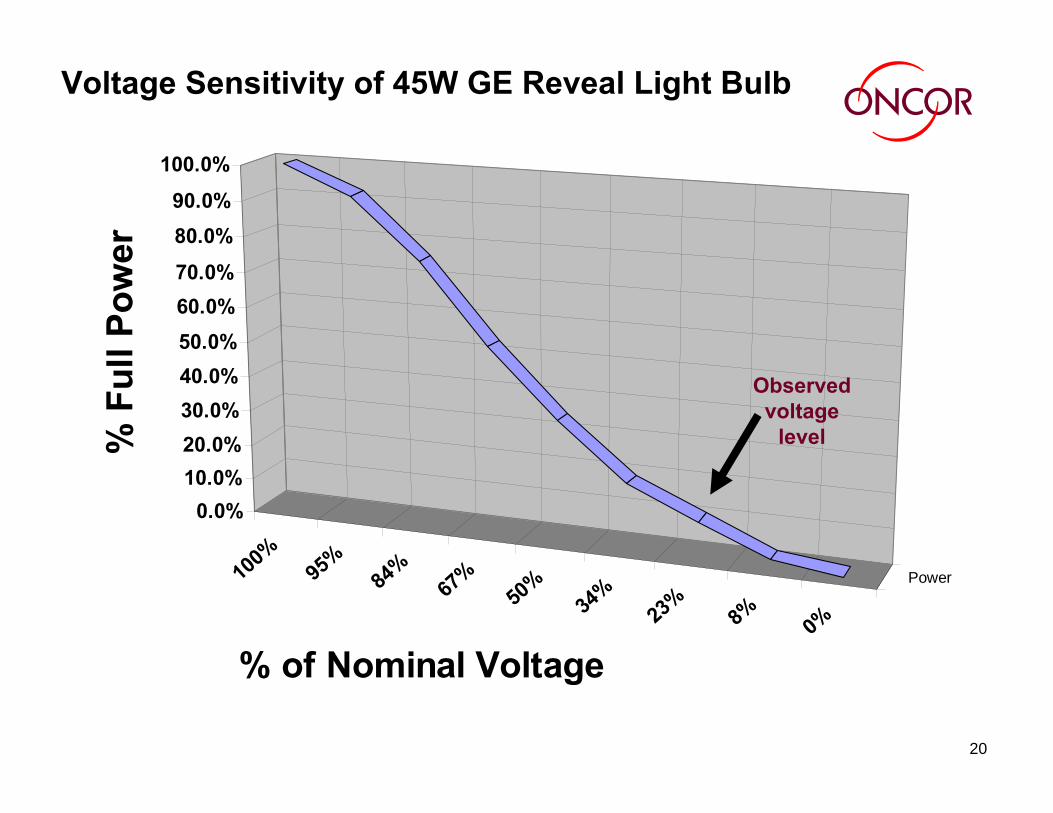
Voltage and Current Measurements During Extended Low Voltage ConditionsMeasurements were taken on an incandescent light bulb in the lab in an
effort to determine the voltage sensitivity of light bulbs and to estimate the amount of load that might be present at each home during reduced voltage conditions.
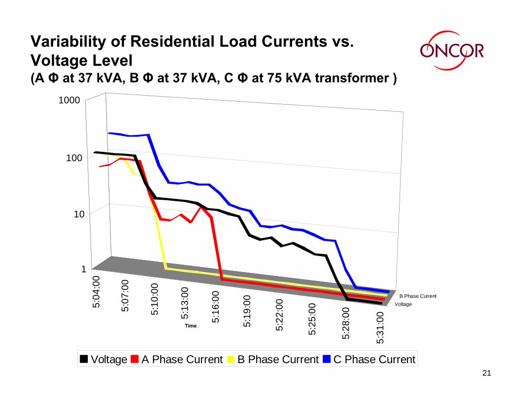
Field measurements of voltage and current using power quality recorders were taken at three selected single-phase padmounttransformers during an outage to balance the subdivision load across all three phases. Measurements were also taken at the 1000 kVA and 500 kVA three-phase transformers. The voltage and current levels that occurred during the open phase conditions were recorded.
The load measurement results are shown on the following slides.
20
Voltage Sensitivity of 45W GE Reveal Light Bulb
100%
95%
84%
67%
50%
34%
23%
8% 0%
Power
0.0%10.0%20.0%30.0%40.0%50.0%60.0%70.0%
80.0%90.0%
100.0%
% F
ull P
ower
% of Nominal Voltage
Observed voltage
level
21
Variability of Residential Load Currents vs. Voltage Level(A Φ at 37 kVA, B Φ at 37 kVA, C Φ at 75 kVA transformer )
5:04
:00
5:07
:00
5:10
:00
5:13
:00
5:16
:00
5:19
:00
5:22
:00
5:25
:00
5:28
:00
5:31
:00
VoltageB Phase Current
1
10
100
1000
Time
Voltage A Phase Current B Phase Current C Phase Current
22
Load Characteristics under Low Voltage Conditions
“Modern loads typically have a higher power factor, wider voltage range, and more constant power characteristics than their predecessors. In general, modern controlled loads (e.g. office equipment containing switching power supplies; adjustable frequency drives), drop out at a minimum voltage and do not restart until near rated voltage or until manually reset.” [1]
“Motors used in small residential air conditioners and refrigerators tend to stall when the voltage is reduced below 60% for 5 cycles or longer.
Under these conditions, the motor will continue to draw very high current, depending on the voltage level, approaching the locked-rotor current at rated voltage. The motor will normally trip on thermal overload after 3 to 30 seconds.” [2]
“Larger commercial and industrial air conditioners are typicallyequipped with an undervoltage protection relay that trips-off the unit for voltages less than 70% in 0.1 seconds.” [3]
23
Conclusions
An open fuse doesn’t mean the line is de-energized. In this case, the primary voltage was measured in excess of 3 kV on the open phases at the fuse location!
Utility personnel have been trained to consider any conductor to be energized unless it has been de-energized and grounded.
Customers need to be told the same message.
The low voltage condition caused by an open conductor situation will last as long as it takes utility personnel to respond to the outage.
This low voltage condition should not result in damage to the customer’s appliances. The customer can trip the main breaker until the electrical service returns to normal.
Remember, It’s not dead unless it is grounded!
24
Acknowledgements
We thank the ABB company for their assistance in documenting theperformance of the five legged core transformer under various open phase conditions. We thank those who organized, commissioned and performed the testing: Phil Smith, John Crotty, P.E., Susmitha Tarlapally and VlatkoTanaskoski.
We thank the Oncor personnel who initially observed and reported this condition and performed the subsequent field measurements: Joe Loosier and Kenneth Townsend.
25
References
1. Les M. Hajagos, Behnam Danai; “Laboratory Measurements and Models of Modem Loads and Their Effect on Voltage Stability Studies”, IEEE Transactions on Power Systems, Vol. 13, No. 2, May 1998.
2. Williams, B.R.; Schmus, W.R.; Dawson, D.C.; “Transmission Voltage Recovery Delayed by Stalled Air-Conditioner Compressors”, IEEE Transactions on Power Systems, Vol. 7, No. 3, pp. 1173-1181, August 1992.
3. J. W. Shaffer, “Air Conditioner Response to Transmission Faults”, IEEE Transactions on Power Systems, Vol. 12, No. 2, pp 614-621, May 1997.
4. IEEE C57.105-1978, IEEE guide for application of transformer connections in three-phase distribution systems.