Embed Size (px)
Citation preview
www.lasertools.co.uk www.lasertools.co.uk
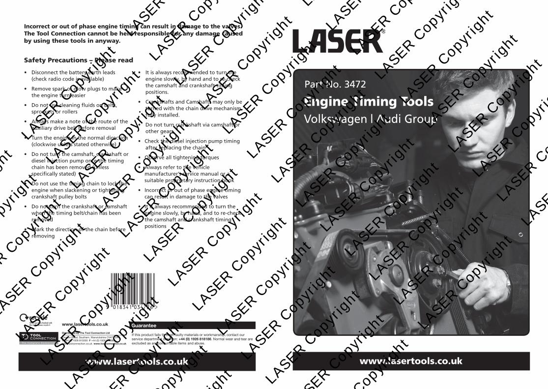
Part No. 3472
Engine Timing ToolsVolkswagen | Audi Group
Incorrect or out of phase engine timing can result in damage to the valves. The Tool Connection cannot be held responsible for any damage caused by using these tools in anyway.
Safety Precautions – Please read
• Disconnect the battery earth leads (check radio code is available)
• Remove spark or glow plugs to make the engine turn easier
• Do not use cleaning fluids on belts, sprockets or rollers
• Always make a note of the route of the auxiliary drive belt before removal
• Turn the engine in the normal direction (clockwise unless stated otherwise)
• Do not turn the camshaft, crankshaft or diesel injection pump once the timing chain has been removed (unless specifically stated)
• Do not use the timing chain to lock the engine when slackening or tightening crankshaft pulley bolts
• Do not turn the crankshaft or camshaft when the timing belt/chain has been removed
• Mark the direction of the chain before removing
• It is always recommended to turn the engine slowly, by hand and to re-check the camshaft and crankshaft timing positions.
• Crankshafts and Camshafts may only be turned with the chain drive mechanism fully installed.
• Do not turn crankshaft via camshaft or other gears
• Check the diesel injection pump timing after replacing the chain
• Observe all tightening torques
• Always refer to the vehicle manufacturer’s service manual or a suitable proprietary instruction book
• Incorrect or out of phase engine timing can result in damage to the valves
• It is always recommended to turn the engine slowly, by hand, and to re-check the camshaft and crankshaft timing positions
LASE
R Cop
yrig
ht
LASE
R Cop
yrig
ht
LASE
R Cop
yrig
ht
LASE
R Cop
yrig
ht
LA
SER C
opyr
ight
L
ASER C
opyr
ight
L
ASER C
opyr
ight
L
ASER C
opyr
ight
LA
SER C
opyr
ight
L
ASER C
opyr
ight
L
ASER C
opyr
ight
L
ASER C
opyr
ight
LA
SER C
opyr
ight
L
ASER C
opyr
ight
L
ASER C
opyr
ight
L
ASER C
opyr
ight
LA
SER C
opyr
ight
L
ASER C
opyr
ight
L
ASER C
opyr
ight
L
ASER C
opyr
ight
LA
SER C
opyr
ight
L
ASER C
opyr
ight
L
ASER C
opyr
ight
L
ASER C
opyr
ight
LA
SER C
opyr
ight
L
ASER C
opyr
ight
L
ASER C
opyr
ight
L
ASER C
opyr
ight
LA
SER C
opyr
ight
L
ASER C
opyr
ight
L
ASER C
opyr
ight
L
ASER C
opyr
ight
LA
SER C
opyr
ight
L
ASER C
opyr
ight
L
ASER C
opyr
ight
L
ASER C
opyr
ight
LA
SER C
opyr
ight
L
ASER C
opyr
ight
L
ASER C
opyr
ight
L
ASER C
opyr
ight
LA
SER C
opyr
ight
L
ASER C
opyr
ight
L
ASER C
opyr
ight
L
ASER C
opyr
ight
LA
SER C
opyr
ight
L
ASER C
opyr
ight
L
ASER C
opyr
ight
L
ASER C
opyr
ight
LA
SER C
opyr
ight
L
ASER C
opyr
ight
L
ASER C
opyr
ight
L
ASER C
opyr
ight
2 11
www.eldontools. www.lasertools.co.ukwww.lasertools.co.uk
Plan Layout Instruction (DE)
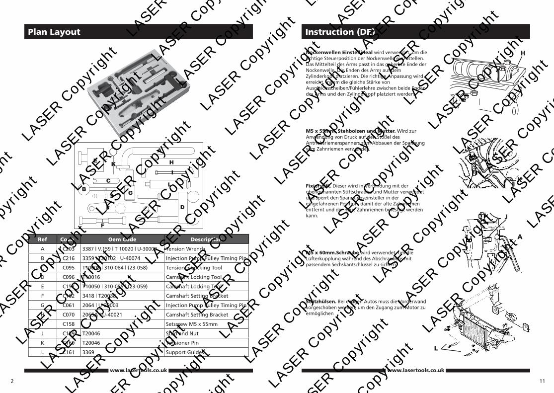
Ref Code Oem Code Description
A C203 3387 | V.159 | T 10020 | U-30009 Tension Wrench
B C216 3359 | T20102 | U-40074 Injection Pump Pulley Timing Pin
C C095 T10008 | 310-084 | (23-058) Tensioner Locking Tool
D C096 T10016 Camshaft Locking Tool
E C157 T10050 | 310-085 | (23-059) Camshaft Locking Tool
F C162 3418 | T20038 Camshaft Setting Bracket
G C061 2064 | U-20003 Injection Pump Pulley Timing Pin
H C070 2065A | U-40021 Camshaft Setting Bracket
I C158 Setscrew M5 x 55mm
J C159 T20046 Stud and Nut
K C160 T20046 Tensioner Pin
L C161 3369 Support Guides
Nockenwellen Einstellineal wird verwendet, um die richtige Steuerposition der Nockenwelle einzustellen. Das Mittelteil des Arms passt in das gekerbte Ende der Nockenwelle. Die Enden des Arms auf dem Zylinderkopf platzieren. Die richtige Anpassung wird erreicht, indem die gleiche Stärke von Ausgleichsscheiben/Fühlerlehre zwischen beide Enden des Arms und den Zylinderkopf platziert werden.
M5 x 55mm. Stehbolzen und Mutter. Wird zur Anwendung von Druck auf den Stößel des Antriebsriemenspanners zum Abbauen der Spannung vom Zahnriemen verwendet.
Fixierstift. Dieser wird in Verbindung mit der obengenannten Stiftschraube und Mutter verwendet und sperrt den Spannungseinsteller in der eingefahrenen Position, damit der alte Zahnriemen entfernt und der neue Zahnriemen befestigt werden kann.
M5 x 60mm.Schraube wird verwendet, um die Lüfterkupplung während des Abschraubens mit passendem Sechskantschlüssel zu sichern.
Stützhülsen. Bei einigen Autos muss die Vorderwand vorgeschoben werden, um den Zugang zum Motor zu ermöglichen
H
A
L
J
J
K
LASE
R Cop
yrig
ht
LASE
R Cop
yrig
ht
LASE
R Cop
yrig
ht
LASE
R Cop
yrig
ht
LA
SER C
opyr
ight
L
ASER C
opyr
ight
L
ASER C
opyr
ight
L
ASER C
opyr
ight
LA
SER C
opyr
ight
L
ASER C
opyr
ight
L
ASER C
opyr
ight
L
ASER C
opyr
ight
LA
SER C
opyr
ight
L
ASER C
opyr
ight
L
ASER C
opyr
ight
L
ASER C
opyr
ight
LA
SER C
opyr
ight
L
ASER C
opyr
ight
L
ASER C
opyr
ight
L
ASER C
opyr
ight
LA
SER C
opyr
ight
L
ASER C
opyr
ight
L
ASER C
opyr
ight
L
ASER C
opyr
ight
LA
SER C
opyr
ight
L
ASER C
opyr
ight
L
ASER C
opyr
ight
L
ASER C
opyr
ight
LA
SER C
opyr
ight
L
ASER C
opyr
ight
L
ASER C
opyr
ight
L
ASER C
opyr
ight
LA
SER C
opyr
ight
L
ASER C
opyr
ight
L
ASER C
opyr
ight
L
ASER C
opyr
ight
LA
SER C
opyr
ight
L
ASER C
opyr
ight
L
ASER C
opyr
ight
L
ASER C
opyr
ight
LA
SER C
opyr
ight
L
ASER C
opyr
ight
L
ASER C
opyr
ight
L
ASER C
opyr
ight
LA
SER C
opyr
ight
L
ASER C
opyr
ight
L
ASER C
opyr
ight
L
ASER C
opyr
ight
LA
SER C
opyr
ight
L
ASER C
opyr
ight
L
ASER C
opyr
ight
L
ASER C
opyr
ight
10
www.lasertools.co.uk
Instruction (DE)
3
Applications
The application list for this product has been compiled cross referencing the OEM Tool Code with the Component Code.
In most cases the tools are specific to this type of engine and are necessary for Cam belt or chain maintenance.
If the engine has been identified as an interference engine valve to piston damage will occur if the engine is run with a broken Cam belt.
A compression check of all cylinders should be performed before removing the cylinder head.
Always consult a suitable work shop manual before attempting to change the Cam belt or Chain.
Autodata
Our applications data is supplied by Autodata and we are able to supply this data to you in a PDF format.
If this is a specific kit for a group of engine codes the application list has been supplied showing the main vehicles this kit is designed for and does not list every model each pin fits.
If this is a master kit then all vehicles are included.
The data is the copyright of Tool Connection and should not be reproduced.
If the application data is extensive we have included a CD with the application list in .pdf format.
Languages
We have also included where possible translations for the instructions in the following languages:
• French
• Spanish
• German
• Portuguese
• Italian
• Dutch
The use of these engine timing tools is purely down to the user’s discretion and Tool Connection cannot be held responsible for any damage caused what so ever.
ALWAYS USE A REPUTABLE WORKSHOP MANUAL
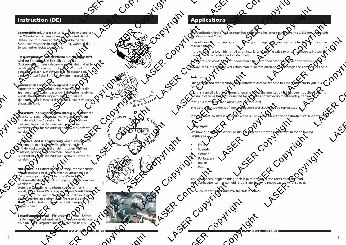
Spannschlüssel. Dieser Schlüssel wird beim Einpassen der Zahnriemen verwendet und ist erforderlich beim Halten und Positionieren der Riemenscheibe des Zahnriemenspanners in einer Richtung, während die Zentralmutter festgezogen wird.
Einspritzpumpe Riemenscheiben-Sicherungsstift wird zur Sicherung der Einstellposition der Nockenwelle zur Einspritzpumpe verwendet und ist für zweiteilige Kettenräder, die durch drei Schrauben gesichert werden. Der Stift ist speziell ausgehöhlt, damit Kraftstoff den Stift nicht wieder herausdrückt
Spannrollen-Fixierwerkzeug wird in das automatische Spannmodul eingesetzt, nachdem die Spannung gelöst, aber bevor der Zahnriemen entfernt wurde. Dieses Werkzeug verbleibt dort, bis die Spannung nach Einsetzen des neuen Riemens wieder eingestellt wird.
Nockenwellen-Sicherungswerkzeug wird durch die zwei Kettenräder der Nockenwelle geführt und im Zylinderkopf zum Einstellen der richtigen Position platziert, bevor der Zahnriemen und/oder der Antriebsriemen für die Auslassnockenwelle entfernt werden.
Kurbelwellen-Fixierwerkzeug wird durch die zwei Kettenräder der Nockenwelle geführt und im Zylinderkopf zum Einstellen der richtigen Position platziert, bevor der Zahnriemen und/oder der Antriebsriemen für die Auslassnockenwelle entfernt werden.
Nockenwellen Einstellhalter ermöglicht die richtige Motorsteuerung nach der einfachen Entnahme der Vakuumpumpe und spart Zeit und Kosten, da Nockenwellendeckel und Dichtung nicht abgenommen werden müssen. Wenn der Zahnriemen gerissen ist oder entfernt wurde, kann dieses Werkzeug mit einem Maulschlüssel benutzt werden, um die Nockenwelle in die richtige Einstellposition zu drehen. Dann werden die zwei Passschrauben befestigt, um die richtige Anpassung zu ermöglichen.
Einspritzpumpenrad – Fixierdorn beträgt 15,4mm im Durchmesser und wird bei Motoren verwendet, die ein einteiliges Einspritzpumpen-Kettenrad haben.
A
C
FE
www.lasertools.co.uk
D
LASE
R Cop
yrig
ht
LASE
R Cop
yrig
ht
LASE
R Cop
yrig
ht
LASE
R Cop
yrig
ht
LA
SER C
opyr
ight
L
ASER C
opyr
ight
L
ASER C
opyr
ight
L
ASER C
opyr
ight
LA
SER C
opyr
ight
L
ASER C
opyr
ight
L
ASER C
opyr
ight
L
ASER C
opyr
ight
LA
SER C
opyr
ight
L
ASER C
opyr
ight
L
ASER C
opyr
ight
L
ASER C
opyr
ight
LA
SER C
opyr
ight
L
ASER C
opyr
ight
L
ASER C
opyr
ight
L
ASER C
opyr
ight
LA
SER C
opyr
ight
L
ASER C
opyr
ight
L
ASER C
opyr
ight
L
ASER C
opyr
ight
LA
SER C
opyr
ight
L
ASER C
opyr
ight
L
ASER C
opyr
ight
L
ASER C
opyr
ight
LA
SER C
opyr
ight
L
ASER C
opyr
ight
L
ASER C
opyr
ight
L
ASER C
opyr
ight
LA
SER C
opyr
ight
L
ASER C
opyr
ight
L
ASER C
opyr
ight
L
ASER C
opyr
ight
LA
SER C
opyr
ight
L
ASER C
opyr
ight
L
ASER C
opyr
ight
L
ASER C
opyr
ight
LA
SER C
opyr
ight
L
ASER C
opyr
ight
L
ASER C
opyr
ight
L
ASER C
opyr
ight
LA
SER C
opyr
ight
L
ASER C
opyr
ight
L
ASER C
opyr
ight
L
ASER C
opyr
ight
LA
SER C
opyr
ight
L
ASER C
opyr
ight
L
ASER C
opyr
ight
L
ASER C
opyr
ight
4
Instruction (GB)
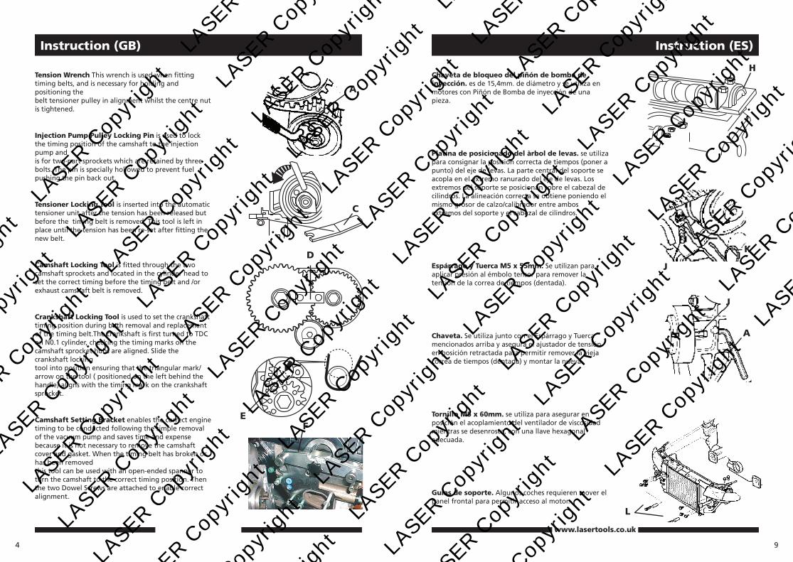
Tension Wrench This wrench is used when fitting timing belts, and is necessary for holding and positioning the belt tensioner pulley in alignment whilst the centre nut is tightened.
Injection Pump Pulley Locking Pin is used to lock the timing position of the camshaft to the injection pump and is for two-part sprockets which are retained by three bolts. The pin is specially hollowed to prevent fuel pushing the pin back out.
Tensioner Locking Tool is inserted into the automatic tensioner unit after the tension has been released but before the timing belt is removed. This tool is left in place until the tension has been re-set after fitting the new belt.
Camshaft Locking Tool is fitted through the two camshaft sprockets and located in the cylinder head to set the correct timing before the timing belt and /or exhaust camshaft belt is removed.
Crankshaft Locking Tool is used to set the crankshaft timing position during both removal and replacement of the timing belt.The crankshaft is first turned to TDC on N0.1 cylinder, checking the timing marks on the camshaft sprocket hubs are aligned. Slide the crankshaft locking tool into position ensuring that the triangular mark/ arrow on the tool ( positioned on the left behind the handle) aligns with the timing mark on the crankshaft sprocket.
Camshaft Setting Bracket enables the correct engine timing to be conducted following the simple removal of the vacuum pump and saves time and expense because it is not necessary to remove the camshaft cover and gasket. When the timing belt has broken or has been removed this tool can be used with an open-ended spanner to turn the camshaft to the correct timing position. Then the two Dowel Screws are attached to enable correct alignment.
A
C
FE
D
9
www.lasertools.co.uk
Instruction (ES)
Chaveta de bloqueo del piñón de bomba de inyección. es de 15,4mm. de diámetro y se utiliza en motores con Piñón de Bomba de inyección de una pieza.
Platina de posicionado del àrbol de levas. se utiliza para consignar la posición correcta de tiempos (poner a punto) del eje de levas. La parte central del soporte se acopla en el extremo ranurado del eje de levas. Los extremos del soporte se posicionan sobre el cabezal de cilindros. La alineación correcta se obtiene poniendo el mismo grosor de calzo/calibrador entre ambos extremos del soporte y el cabezal de cilindros.
Espárrago y Tuerca M5 x 55mm. Se utilizan para aplicar presión al émbolo tensor para remover la tensión de la correa de tiempos (dentada).
Chaveta. Se utiliza junto con el Espárrago y Tuerca mencionados arriba y asegura el ajustador de tensión en posición retractada para permitir remover la vieja correa de tiempos (dentada) y montar la nueva.
Tornillo M5 x 60mm. se utiliza para asegurar en posición el acoplamiento del ventilador de viscosidad mientras se desenrosca, con una llave hexagonal adecuada.
Guías de soporte. Algunos coches requieren mover el panel frontal para permitir acceso al motor.
H
L
J
J
K
A
LASE
R Cop
yrig
ht
LASE
R Cop
yrig
ht
LASE
R Cop
yrig
ht
LASE
R Cop
yrig
ht
LA
SER C
opyr
ight
L
ASER C
opyr
ight
L
ASER C
opyr
ight
L
ASER C
opyr
ight
LA
SER C
opyr
ight
L
ASER C
opyr
ight
L
ASER C
opyr
ight
L
ASER C
opyr
ight
LA
SER C
opyr
ight
L
ASER C
opyr
ight
L
ASER C
opyr
ight
L
ASER C
opyr
ight
LA
SER C
opyr
ight
L
ASER C
opyr
ight
L
ASER C
opyr
ight
L
ASER C
opyr
ight
LA
SER C
opyr
ight
L
ASER C
opyr
ight
L
ASER C
opyr
ight
L
ASER C
opyr
ight
LA
SER C
opyr
ight
L
ASER C
opyr
ight
L
ASER C
opyr
ight
L
ASER C
opyr
ight
LA
SER C
opyr
ight
L
ASER C
opyr
ight
L
ASER C
opyr
ight
L
ASER C
opyr
ight
LA
SER C
opyr
ight
L
ASER C
opyr
ight
L
ASER C
opyr
ight
L
ASER C
opyr
ight
LA
SER C
opyr
ight
L
ASER C
opyr
ight
L
ASER C
opyr
ight
L
ASER C
opyr
ight
LA
SER C
opyr
ight
L
ASER C
opyr
ight
L
ASER C
opyr
ight
L
ASER C
opyr
ight
LA
SER C
opyr
ight
L
ASER C
opyr
ight
L
ASER C
opyr
ight
L
ASER C
opyr
ight
LA
SER C
opyr
ight
L
ASER C
opyr
ight
L
ASER C
opyr
ight
L
ASER C
opyr
ight
5
Instruction (GB)
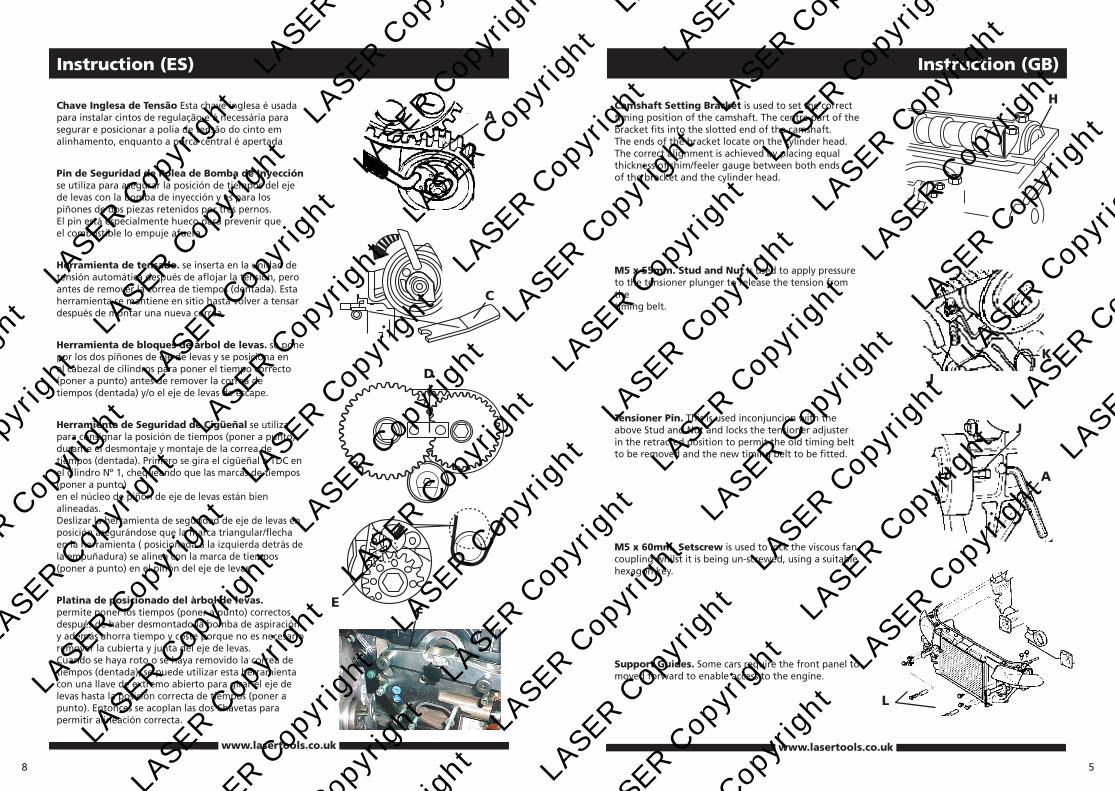
Camshaft Setting Bracket is used to set the correct timing position of the camshaft. The centre part of the bracket fits into the slotted end of the camshaft. The ends of the bracket locate on the cylinder head. The correct alignment is achieved by placing equal thickness of shim/feeler gauge between both ends of the bracket and the cylinder head.
M5 x 55mm. Stud and Nut Is used to apply pressure to the tensioner plunger to release the tension from the timing belt.
Tensioner Pin. This is used inconjuncion with the above Stud and Nut and locks the tensioner adjuster in the retracted position to permit the old timing belt to be removed and the new timing belt to be fitted.
M5 x 60mm. Setscrew is used to lock the viscous fan coupling whilst it is being un-screwed, using a suitable hexagon key.
Support Guides. Some cars require the front panel to moved forward to enable access to the engine.
H
L
J
J
K
A
www.lasertools.co.uk
8
www.lasertools.co.uk
Instruction (ES)
Chave Inglesa de Tensão Esta chave inglesa é usada para instalar cintos de regulação e é necessária para segurar e posicionar a polia de tensão do cinto em alinhamento, enquanto a porca central é apertada
Pin de Seguridad de Polea de Bomba de Inyección se utiliza para asegurar la posición de tiempos del eje de levas con la bomba de inyección y es para los piñones de dos piezas retenidos por tres pernos. El pin está especialmente hueco para prevenir que el combustible lo empuje afuera.
Herramienta de tensado. se inserta en la unidad de tensión automática después de aflojar la tensión, pero antes de remover la correa de tiempos (dentada). Esta herramienta se mantiene en sitio hasta volver a tensar después de montar una nueva correa.
Herramienta de bloques de àrbol de levas. se pone por los dos piñones de eje de levas y se posiciona en el cabezal de cilindros para poner el tiempo correcto (poner a punto) antes de remover la correa de tiempos (dentada) y/o el eje de levas de escape.
Herramienta de Seguridad de Cigüeñal se utiliza para consignar la posición de tiempos (poner a punto) durante el desmontaje y montaje de la correa de tiempos (dentada). Primero se gira el cigüeñal a TDC en el cilindro Nº 1, chequeando que las marcas de tiempos (poner a punto) en el núcleo de piñón de eje de levas están bien alineadas. Deslizar la herramienta de seguridad de eje de levas en posición asegurándose que la marca triangular/flecha en la herramienta ( posicionada a la izquierda detrás de la empuñadura) se alinea con la marca de tiempos (poner a punto) en el piñón del eje de levas.
Platina de posicionado del àrbol de levas. permite poner los tiempos (poner a punto) correctos después de haber desmontado la bomba de aspiración y además ahorra tiempo y coste porque no es necesario remover la cubierta y junta del eje de levas. Cuando se haya roto o se haya removido la correa de tiempos (dentada), se puede utilizar esta herramienta con una llave de extremo abierto para girar el eje de levas hasta la posición correcta de tiempos (poner a punto). Entonces se acoplan las dos Chavetas para permitir alineación correcta.
A
C
D
FE
LASE
R Cop
yrig
ht
LASE
R Cop
yrig
ht
LASE
R Cop
yrig
ht
LASE
R Cop
yrig
ht
LA
SER C
opyr
ight
L
ASER C
opyr
ight
L
ASER C
opyr
ight
L
ASER C
opyr
ight
LA
SER C
opyr
ight
L
ASER C
opyr
ight
L
ASER C
opyr
ight
L
ASER C
opyr
ight
LA
SER C
opyr
ight
L
ASER C
opyr
ight
L
ASER C
opyr
ight
L
ASER C
opyr
ight
LA
SER C
opyr
ight
L
ASER C
opyr
ight
L
ASER C
opyr
ight
L
ASER C
opyr
ight
LA
SER C
opyr
ight
L
ASER C
opyr
ight
L
ASER C
opyr
ight
L
ASER C
opyr
ight
LA
SER C
opyr
ight
L
ASER C
opyr
ight
L
ASER C
opyr
ight
L
ASER C
opyr
ight
LA
SER C
opyr
ight
L
ASER C
opyr
ight
L
ASER C
opyr
ight
L
ASER C
opyr
ight
LA
SER C
opyr
ight
L
ASER C
opyr
ight
L
ASER C
opyr
ight
L
ASER C
opyr
ight
LA
SER C
opyr
ight
L
ASER C
opyr
ight
L
ASER C
opyr
ight
L
ASER C
opyr
ight
LA
SER C
opyr
ight
L
ASER C
opyr
ight
L
ASER C
opyr
ight
L
ASER C
opyr
ight
LA
SER C
opyr
ight
L
ASER C
opyr
ight
L
ASER C
opyr
ight
L
ASER C
opyr
ight
LA
SER C
opyr
ight
L
ASER C
opyr
ight
L
ASER C
opyr
ight
L
ASER C
opyr
ight
6
www.lasertools.co.uk
Instruction (FR)
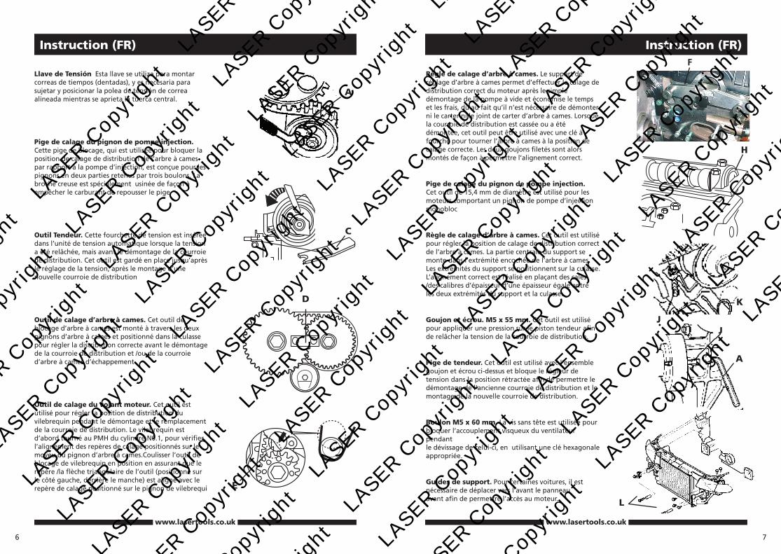
Llave de Tensión Esta llave se utiliza para montar correas de tiempos (dentadas), y es necesaria para sujetar y posicionar la polea de tensión de correa alineada mientras se aprieta la tuerca central.
Pige de calage du pignon de pompe injection. Cette pige de blocage, qui est utilisée pour bloquer la position de calage de distribution de l’arbre à cames par rapport à la pompe d’injection, est conçue pour les pignons en deux parties retenus par trois boulons. La broche creuse est spécialement usinée de façon à empêcher le carburant de repousser le pige
Outil Tendeur. Cette fourchette de tension est insérée dans l’unité de tension automatique lorsque la tension a été relâchée, mais avant le démontage de la courroie de distribution. Cet outil est gardé en place jusqu’après le réglage de la tension, après le montage d’une nouvelle courroie de distribution
Outil de calage d’arbre à cames. Cet outil de blocage d’arbre à cames est monté à travers les deux pignons d’arbre à cames et positionné dans la culasse pour régler la distribution correcte avant le démontage de la courroie de distribution et /ou de la courroie d’arbre à cames d’échappement
Outil de calage du volant moteur. Cet outil est utilisé pour régler la position de distribution du vilebrequin pendant le démontage et le remplacement de la courroie de distribution. Le vilebrequin est d’abord tourné au PMH du cylindre N0.1, pour vérifier l’alignement des repères de calage positionnés sur le moyeu du pignon d’arbre à cames.Coulisser l’outil de blocage de vilebrequin en position en assurant que le repère /la flèche triangulaire de l’outil (positionné sur le côté gauche, derrière le manche) est aligné avec le repère de calage positionné sur le pignon de vilebrequi
A
C
D
E
7
www.lasertools.co.uk
Instruction (FR)
Règle de calage d’arbre à cames. Le support de réglage d’arbre à cames permet d’effectuer le calage de distribution correct du moteur après le simple démontage de la pompe à vide et économise le temps et les frais, dû au fait qu’il n’est nécessaire de démonter ni le carter ni le joint de carter d’arbre à cames. Lorsque la courroie de distribution est cassée ou a été démontée, cet outil peut être utilisé avec une clé à fourche pour tourner l’arbre à cames à la position de calage correcte. Les deux goujons filetés sont alors montés de façon à permettre l’alignement correct.
Pige de calage du pignon de pompe injection. Cet outil de 15,4 mm de diamètre est utilisé pour les moteurs comportant un pignon de pompe d’injection monobloc
Règle de calage d’arbre à cames. Cet outil est utilisé pour régler la position de calage de distribution correct de l’arbre à cames. La partie centrale du support se monte dans l’extrémité encochée de l’arbre à cames. Les extrémités du support se positionnent sur la culasse. L’alignement correct est réalisé en plaçant des cales /des calibres d’épaisseur d’une épaisseur égale entre les deux extrémités du support et la culasse.
Goujon et écrou. M5 x 55 mm. Cet outil est utilisé pour appliquer une pression sur le piston tendeur afin de relâcher la tension de la courroie de distribution.
Pige de tendeur. Cet outil est utilisé avec l’ensemble goujon et écrou ci-dessus et bloque le régleur de tension dans la position rétractée afin de permettre le démontage de l’ancienne courroie de distribution et le montage de la nouvelle courroie de distribution.
Boulon M5 x 60 mm. La vis sans tête est utilisée pour bloquer l’accouplement visqueux du ventilateur pendant le dévissage de celui-ci, en utilisant une clé hexagonale appropriée.
Guides de support. Pour certaines voitures, il est nécessaire de déplacer vers l’avant le panneau avant afin de permettre l’accès au moteur.
H
L
JJ
K
A
F
LASE
R Cop
yrig
ht
LASE
R Cop
yrig
ht
LASE
R Cop
yrig
ht
LASE
R Cop
yrig
ht
LA
SER C
opyr
ight
L
ASER C
opyr
ight
L
ASER C
opyr
ight
L
ASER C
opyr
ight
LA
SER C
opyr
ight
L
ASER C
opyr
ight
L
ASER C
opyr
ight
L
ASER C
opyr
ight
LA
SER C
opyr
ight
L
ASER C
opyr
ight
L
ASER C
opyr
ight
L
ASER C
opyr
ight
LA
SER C
opyr
ight
L
ASER C
opyr
ight
L
ASER C
opyr
ight
L
ASER C
opyr
ight
LA
SER C
opyr
ight
L
ASER C
opyr
ight
L
ASER C
opyr
ight
L
ASER C
opyr
ight
LA
SER C
opyr
ight
L
ASER C
opyr
ight
L
ASER C
opyr
ight
L
ASER C
opyr
ight
LA
SER C
opyr
ight
L
ASER C
opyr
ight
L
ASER C
opyr
ight
L
ASER C
opyr
ight
LA
SER C
opyr
ight
L
ASER C
opyr
ight
L
ASER C
opyr
ight
L
ASER C
opyr
ight
LA
SER C
opyr
ight
L
ASER C
opyr
ight
L
ASER C
opyr
ight
L
ASER C
opyr
ight
LA
SER C
opyr
ight
L
ASER C
opyr
ight
L
ASER C
opyr
ight
L
ASER C
opyr
ight
LA
SER C
opyr
ight
L
ASER C
opyr
ight
L
ASER C
opyr
ight
L
ASER C
opyr
ight
LA
SER C
opyr
ight
L
ASER C
opyr
ight
L
ASER C
opyr
ight
L
ASER C
opyr
ight


