Embed Size (px)
Citation preview
NOTES: ClassNK Technical Information is provided only for the purpose of supplying current information to its readers. ClassNK, its officers, employees and agents or sub-contractors do not warrant the accuracy of the information contained
herein and are not liable for any loss, damage or expense sustained whatsoever by any person caused by use of or reliance on this information.
Back numbers are available on ClassNK Internet Homepage (URL: www.classnk.or.jp).
Subject
Maintenance, inspection and test of Fire-Protection Systems and Appliances on board the Panama-registered ships
Technical Information
No. TEC-0970 Date 31 October 2013
To whom it may concern
The Panama Government has informed ClassNK that Merchant Marine Circular No.281, "Guidelines for the Maintenance and Inspection of Fire-Protection Systems and Appliances", which is in reference to maintenance, inspection and test of Fire-Protection System and Appliances on board the Panama-registered ships, was revised. The essential points of the Guidelines are shown below. The previous ClassNK Technical Information No.TEC-0910 is now superseded. Purpose of the Guidelines Provide the minimum recommended level of maintenance and inspections for the protection system and appliances. It should be noted that the general requirements contained in this Guideline are not an inclusive list of maintenance or inspection items for fire protection systems, fire fighting appliances, and emergency equipment. Application of the Guidelines 1. The Guidelines applies to all Panamanian flag ships including units under MODU code. This
information may be used as a basis for the ship's onboard maintenance plan required by SOLAS regulation II-2/14.
2. The Guidelines will also address maintenance and inspection of fixed carbon dioxide systems or portable fire extinguishers. As for the comprehensive instructions, they are provided in the Guidelines for the maintenance and inspections of fixed carbon dioxide fire extinguishing systems (MSC.1/Circ.1318) for fixed carbon dioxide systems, and in the Improved Guidelines for marine portable fire extinguishers (Resolution A.951 (23)) for portable fire extinguishers.
3. Our surveyors will confirm that the maintenance and testing records of fire protection systems and appliances are on board Panama-registered ships at every survey for Safety Equipment.
4. Where particular arrangements create practical difficulties, alternative testing and maintenance procedures and maintenance period should be consulted directly to the Administration. (See the 1.2.5 of the Guidelines).
The Abstract of the Guidelines is referred to the attachment 1. "General Requirements for the Maintenance and Inspection of Fire-protection Systems and Appliances (Abstract of Merchant Marine Circular No.281)". As necessary, please refer to original text of the Circular (attachment 2.) which is available on Panama Government Internet Homepage (http://www.segumar.com).
(To be continued)
Void

ClassNK Technical Information No. TEC-0970
2
For any questions about the above, please contact: NIPPON KAIJI KYOKAI (ClassNK) Survey Department, Administration Center, Head Office Address: 4-7 Kioi-cho, Chiyoda-ku, Tokyo 102-8567, Japan Tel.: +81-3-5226-2027 Fax: +81-3-5226-2029 E-mail: [email protected]
Attachment:
1. General Requirements for the Maintenance and Inspection of Fire-protection Systems and Appliances (Abstract of Merchant Marine Circular No.281)
2. Merchant Marine Circular No.281, "Guidelines for the Maintenance and Inspection of Fire-Protection Systems and Appliances" (Original)
3. MSC.1/Circ.1318: Guidelines for the Maintenance and Inspections of Fixed Carbon Dioxide Fire-Extinguishing Systems
4. Resolution A.951(23): Improved Guidelines for Marine Portable Fire Extinguishers 5. MSC.1/Circ.1312: Revised Guidelines for the Performance and Testing Criteria, and Survey of
Foam Concentrates for Fixed Fire-Extinguishing Systems 6. MSC.1/Circ.798: Guidelines for Performance and Testing Criteria and Surveys of
Medium-Expansion Concentrates for Fire-Extinguishing Systems 7. MSC.1/Circ.670: Guidelines for Performance and Testing Criteria and Surveys of
High-Expansion Concentrates for Fire-Extinguishing Systems 8. MSC/Circ.600: Annual Leakage Check of Halon Fire-Extinguishing Systems Vo
id
Attachment 1. General Requirements for the Maintenance and Inspection of
Fire-protection Systems and Appliances (Abstract of Merchant Marine Circular No.281)
1. General Requirements for the Maintenance and Inspection of Fire-protection Systems
and Appliances.
1.1 Operational readiness
1.1.1 All fire protection system and appliances should be, at all times, in good order and
readily available for immediate use while the ship is in service. If a fire protection
system is undergoing maintenance, testing or repair, then suitable arrangements should
be made to ensure safety is not diminished through the provisions of alternative fixed or
portable fire protection equipment or other measures. The onboard maintenance plan
should include provisions for this purpose.
1.2 Maintenance and Testing
1.2.1 Onboard maintenance and inspections should be carried out in accordance with the
ship's maintenance plan.
1.2.2 Certain maintenance procedures and inspections may be performed by competent crew
members who have at least completed an advanced fire-fighting training course of
STCW, while others should be performed by persons specially trained in the
maintenance of such systems. The on board maintenance plan should indicate which
parts of the recommended inspections and maintenance are to be completed by trained
personnel.
1.2.3 Inspections should be carried out by the crew to ensure that the indicated weekly,
monthly, quarterly, annual, two-year, five-year and ten-year actions are taken for the
specified equipment, if provided. Records of the inspections should be carried on board
the ship, or may be computer based. In cases where the inspections and maintenance are
carried out by trained service technicians other than the ship's crew, inspection reports
should be provided at the completion of the testing.
1.2.4 In addition to the onboard maintenance and inspections stated in these circular,
manufacturer's maintenance and inspection guidelines should be followed.
1.2.5 Where particular arrangements create practical difficulties, alternative testing and
maintenance procedures should be consulted directly to the Administration.
1.3 Weekly Testing and Inspections
Attachment 1. to ClassNK Technical Information No.TEC-0970
Void

1.3.1 Fixed fire detection and alarm systems:
a. Verify all fire detection and fire alarm control panel indicators are functional by
operating the lamp/indicator test switch.
1.3.2 Fixed gas fire-extinguishing systems:
a. Verify all fixed fire-extinguishing system control panel indicators are functional by
operating the lamp/indicator test switch.
b. Verify all control/section valves are in the correct position.
1.3.3 Fire doors:
a. Verify all fire door control panel indicators, if provided, are functional by operating the
lamp/indicator switch.
1.3.4 Public address and general alarm systems:
a. Verify all public address systems and general alarm systems are functioning properly.
1.3.5 Breathing apparatus:
a. Examine all breathing apparatus and EEBD cylinder gauges to confirm they are in the
correct pressure range.
1.3.6 Low location lighting:
a. Verify low location lighting systems are functional by switching off normal lighting in
selected locations.
1.3.7 Water mist, water spray and sprinkler systems:
a. Verify all control panel indicators and alarms are functional.
b. Visually inspect pump unit and its fittings.
c. Check the pump unit valve positions, if valves are not locked, as applicable.
1.4 Monthly testing and inspections
Monthly inspections should be carried out to ensure that the indicated actions are taken
for the specified equipment:
1.4.1 Fire mains, fire pumps, hydrants, hoses and nozzles
a. Verify all fire hydrants, hose and nozzles are in place, properly arranged, and are in
serviceable condition.
b. Operate all fire pumps to confirm that they continue to supply adequate pressure.
c. Emergency fire pump fuel supply adequate, and heating system in satisfactory condition,
if applicable.
1.4.2 Fixed gas fire-extinguishing systems
a. Verify containers/cylinders fitted with pressure gauges are in the proper range and the
installation free from leakage.
1.4.3 Foam fire-extinguishing systems
Void
a. Verify all control and section valves are in the proper open or closed position, and all
pressure gauges are in the proper range.
1.4.4 Water mist, water spray and sprinkler systems
a. Verify all control, pump unit and section valves are in the proper open or closed
position.
b. Verify sprinkler pressure tanks or other means have correct levels of water.
c. Test automatic starting arrangements on all system pumps so designed;
d. Verify all standby pressure and air/gas pressure gauges are within the proper pressure
ranges; and
e. Test a selected sample of system section valves for flow and proper initiation of
alarms.(Note – The valves selected for testing should be chosen to ensure that all valves
are tested within a oneyear period.)
1.4.5 Firefighter's outfits
a. Verify lockers providing storage for firefighting equipment contain their full inventory
and equipment is in serviceable condition.
1.4.6 Fixed dry chemical powder systems
a. Verify all control and section valves are in the proper open or closed position, and all
pressure gauges are in the proper range.
1.4.7 Fixed aerosol extinguishing systems
a. Verify all electrical connections and/or manual operating stations are properly arranged,
and are in proper condition.
b. verify the actuation system/control panel circuits are within manufacturer's
specifications.
1.4.8 Portable foam applicators
a. Verify all portable foam applicators are in place, properly arranged, and are in proper
condition.
1.4.9 Wheeled (mobile) fire extinguishers
a. Verify all extinguishers are in place, properly arranged, and are in proper condition.
1.4.10 Fixed fire detection and alarm systems
a. Test a sample of detectors and manual call points so that all devices have been tested
within five years. For very large systems the sample size should be determined by the
Administration.
1.5 Quarterly testing and inspections
Quarterly inspections should be carried out to ensure that the actions are taken for the
specified equipment.
Void

1.5.1 Fire mains, fire pumps, hydrants, hoses and nozzles
a. Verify international shore connection(s) is in serviceable condition.
1.5.2 Foam fire-extinguishing systems
a. Verify the proper quantity of foam concentrate is provided in the foam system.
1.5.3 Ventilation systems and fire dampers
a. Test all fire dampers for local operation.
1.5.4 Fire doors:
a. Test all fire doors located in main vertical zone bulkheads for local operation.
1.6 Annual testing and inspections.
Annual inspections should be carried out to ensure that the indicated actions are taken
for the specified equipment:
1.6.1 Fire mains, fire pumps, hydrants, hoses and nozzles
a. Visually inspect all accessible components for proper condition.
b. Flow test all fire pumps for proper pressure and capacity. Test emergency fire pump
with isolation valves closed.
c. Test all hydrant valves for proper operation.
d. Pressure test a sample of fire hoses at the maximum fire main pressure, so that all fire
hoses are tested within five years.
e. Verify all fire pump relief valves, if provided, are properly set.
f. Examine all filters/strainers to verify they are free of debris and contamination.
g. Nozzle size/type correct, maintained and working.
1.6.2 Fixed fire detection and fire alarm systems
a. Test all fire detection systems and fire detection systems used to automatically release
fire-extinguishing systems for proper operation, as appropriate.
b. Visually inspect all accessible detectors for evidence of tampering obstruction, etc., so
that all detectors are inspected within one year.
c. Test emergency power supply switchover.
1.6.3 Fixed gas fire-extinguishing systems
a. Visually inspect all accessible components for proper condition.
b. Externally examine all high pressure cylinders for evidence of damage or corrosion.
c. Check the hydrostatic test date of all storage containers.
d. Functionally test all fixed system audible and visual alarms.
e. Verify all control/section valves are in the correct position.
f. Check the connections of all pilot release piping and tubing for tightness.
g. Examine all flexible hoses in accordance with manufacturer's recommendations.
Void

h. Test all fuel shut-off controls connected to fire-protection systems for proper operation.
i. The boundaries of the protected space should be visually inspected to confirm that no
modifications have been made to the enclosure that have created uncloseable openings
that would render the system ineffective.
j. If cylinders are installed inside the protected space, verify the integrity of the double
release lines inside the protected space, and check low pressure or circuit integrity
monitors on release cabinet, as applicable.
1.6.4 Foam fire-extinguishing systems
a. Visually inspect all accessible components for proper condition.
b. Functionally test all fixed system audible alarms.
c. Flow test all water supply and foam pumps for proper pressure and capacity, and
confirm flow at the required pressure in each section (Ensure all piping is thoroughly
flushed with fresh water after service.)
d. Test all system cross connections to other sources of water supply for proper operation.
e. Verify all pump relief valves, if provided, are properly set.
f. Examine all filters/strainers to verify they are free of debris and contamination.
g. Verify all control/section valves are in the correct position.
h. Blow dry compressed air or nitrogen through the discharge piping or otherwise confirm
the pipework and nozzles of high expansion foam systems are clear of any obstructions,
debris and contamination. This may require the removal of nozzles, if applicable.
i. Take samples from all foam concentrates carried on board and subject them to the
periodical control tests in MSC.1/Circ.1312, for low expansion foam, or MSC/Circ.670
for high expansion foam. (Note: Except for non-alcohol resistant foam, the first test
need not be conducted until 3 years after being supplied to the ship.)
j. Test all fuel shut-off controls connected to fire-protection systems for proper operation.
1.6.5 Water mist, water spray and sprinkler systems
a. Verify proper operation of all water mist, water-spray and sprinkler systems using the
test valves for each section.
b. Visually inspect all accessible components for proper condition.
c. Externally examine all high pressure cylinders for evidence of damage or corrosion.
d. Check the hydrostatic test date of all high pressure cylinders.
e. Functionally test all fixed system audible and visual alarms.
f. Flow test all pumps for proper pressure and capacity.
g. Test all antifreeze systems for adequate freeze protection.
h. Test all system cross connections to other sources of water supply for proper operation.
i. Verify all pump relief valves, if provided, are properly set.
Void

j. Examine all filters/strainers to verify they are free of debris and contamination.
k. Verify all control/section valves are in the correct position.
l. Blow dry compressed air or nitrogen through the discharge piping of dry pipe systems,
or otherwise confirm the pipework and nozzles are clear of any obstructions. This may
require the removal of nozzles, if applicable.
m. Test emergency power supply switchover, where applicable.
n. Visually inspect all sprinklers focusing in areas where sprinklers are subject to
aggressive atmosphere (like saunas, spas, kitchen areas) and subject to physical damage
(like luggage handling areas, gyms, play rooms, etc.) so that all sprinklers are inspected
within one year.
o. Check for any changes that may affect the system such as obstructions by ventilation
ducts, pipes, etc.
p. Test a minimum of one section in each open head water mist system by flowing water
through the nozzles. The sections tested should be chosen so that all sections are tested
within a five-year period.
q. Test a minimum of two automatic sprinklers or automatic water mist nozzles for proper
operation.
1.6.6 Ventilation systems and fire dampers
a. Test all fire dampers for remote operation.
b. Verify galley exhaust ducts and filters are free of grease buildup.
c. Test all ventilation controls interconnected with fire-protection systems for proper
operation.
1.6.7 Fire doors
a. Test all remotely controlled fire doors for proper release.
1.6.8 Breathing apparatus
a. Check breathing apparatus air recharging systems, if fitted, for air quality.
b. Check all breathing apparatus face masks and air demand valves are in serviceable
condition.
c. Check EEBDs according to maker's instructions.
1.6.9 Fixed dry chemical powder systems
a. Visually inspect all accessible components for proper condition.
b. Verify the pressure regulators are in proper order and within calibration.
c. Agitate the dry chemical powder charge with nitrogen in accordance with system
manufacturer's instructions.(Note: Due to the powder's affinity for moisture, any
nitrogen gas introduced for agitation must be moisture free.)
1.6.10 Fixed aerosol extinguishing systems
Void

a. Verify condensed or dispersed aerosol generators have not exceeded their mandatory
replacement date. Pneumatic or electric actuators should be demonstrated working, as
far as practicable.
1.6.11 Portable foam applicators
a. Verify all portable foam applicators are set to the correct proportioning ratio for the
foam concentrate supplied and the equipment is in proper order.
b. Verify all portable containers or portable tanks containing foam concentrate remain
factory sealed, and the manufacturer's recommended service life interval has not been
exceeded.
c. Portable containers or portable tanks containing foam concentrate, excluding protein
based concentrates, less than 10 years old, that remain factory sealed can normally be
accepted without the periodical foam control tests required in MSC.1/Circ.1312 being
carried out.
d. Protein based foam concentrate portable containers and portable tanks should be
thoroughly checked and, if more than five years old, the foam concentrate should be
subjected to the periodical foam control tests required in MSC.1/Circ.1312, or renewed.
e. The foam concentrates of any non-sealed portable containers and portable tanks, and
portable containers and portable tanks where production data is not documented, should
be subjected to the periodical foam control tests required in MSC.1/Circ.1312.
1.6.12 Wheeled (mobile) fire extinguishers
a. Perform periodical inspections in accordance with the manufacturer's instructions.
b. Visually inspect all accessible components for proper condition.
c. Check the hydrostatic test date of each cylinder.
d. For dry powder extinguishers, invert extinguisher to ensure powder is agitated.
1.6.13 Galley and deep fat cooking fire-extinguishing systems
a. Check galley and deep fat cooking fire-extinguishing systems in accordance with the
manufacturer's instructions.
1.7 Two-year testing and inspections
Two-year inspections should be carried out to ensure that the indicated actions are taken
for the specified equipment.
1.7.1 Fixed gas fire-extinguishing systems
a. All high pressure extinguishing agents cylinders and pilot cylinders should be weighed
or have their contents verified by other reliable means to confirm that the available
charge in each is above 95 per cent of the nominal charge. Cylinders containing less
than 95 per cent of the nominal charge should be refilled.
Void

b. Blow dry compressed air or nitrogen through the discharge piping or otherwise confirm
the pipe work and nozzles are clear of any obstructions. This may require the removal
of nozzles, if applicable.
1.7.2 Fixed dry chemical powder systems
a. Blow dry nitrogen through the discharge piping to confirm that the pipe work and
nozzles are clear of any obstructions.
b. Operationally test local and remote controls and section valves.
c. Verify the contents of propellant gas cylinders (including remote operating stations)
d. Test a sample of dry chemical powder for moisture content.
e. Subject the powder containment vessel, safety valve and discharge hoses to a full
working pressure test.
1.8 Five-year service
At least once every five years, the following inspections should be carried out for the
specified equipment.
1.8.1 Fixed gas fire-extinguishing systems
a. Perform internal inspection of all control valves.
1.8.2 Foam fire-extinguishing systems
a. Perform internal inspection of all control valves.
b. Flush all high expansion foam system piping with fresh water, drain and purge with air.
c. Check all nozzles to prove they are clear of debris.
d. Test all foam proportioners or other foam mixing devices to confirm that the mixing
ratio tolerance is within +30 to -10% of the nominal mixing ratio defined by the system
approval.
1.8.3 Water mist, water spray and sprinkler systems
a. Flush all ro-ro deck deluge system piping with water, drain and purge with air.
b. Perform internal inspection of all control/section valves.
c. Check condition of any batteries, or renew in accordance with manufacturer's
recommendations.
1.8.4 Breathing apparatus
a. Perform hydrostatic testing of all steel self-contained breathing apparatus cylinders.
Aluminium and composite cylinders should be tested to the satisfaction of the
Administration.
1.8.5 Low-location lighting
a. Test the luminance of all systems in accordance with the procedures in resolution
A.752(18).
Void

1.8.6 Wheeled (mobile) fire extinguishers
a. Visually examine at least one extinguisher of each type manufactured in the same year
and kept on board.
1.9 Ten-year Service
At least once every 10 years, the following inspections should be carried out for the
specified equipment.
1.9.1 Fixed gas fire-extinguishing systems
a. Perform a hydrostatic test and internal examination of 10 per cent of the system's
extinguishing agent and pilot cylinders. If one or more cylinders fail, a total of 50 per
cent of the onboard cylinders should be tested. If further cylinders fail, all cylinders
should be tested.
b. Flexible hoses should be replaced at the intervals recommended by the manufacturer
and not exceeding every 10 years.
c. If permitted by the Administration, visual inspection and NDT (non-destructive testing)
of halon cylinders may be performed in lieu of hydrostatic testing.
1.9.2 Water mist, water spray and sprinkler systems
a. Perform a hydrostatic test and internal examination for gas and water pressure cylinders
according to flag Administration guidelines or, where these do not exist, EN 1968:2002
+ A1.
1.9.3 Fixed dry chemical powder systems
a. Subject all powder containment vessels to hydrostatic or nondestructive testing carried
out by an accredited service agent.
1.9.4 Fixed aerosol extinguishing systems
a. Condensed or dispersed aerosol generators to be renewed in accordance with
manufacturer's recommendations.
1.9.5 Wheeled (mobile) fire extinguishers
a. All extinguishers together with propellant cartridges should be hydrostatically tested by
specially trained persons in accordance with recognized standards or the manufacturer's
instructions.
2 Requirements for Specific Maintenance and Inspection of Portable Fire Extinguishers
2.1 Maintenance and Inspection of Portable Fire Extinguishers
Maintenance and Inspection of Portable Fire Extinguishers should only be undertaken
by, or under the supervision of, a person with demonstrable competence or an
accredited service company, based on the Resolution A 951(23) and manufacture’s
Void

recommendations.
2.2 Refilling for portable fire extinguishers
Periodic refilling of the cylinders should be in accordance with the manufacturer's
recommendations. Only refills approved for the extinguisher may be used for
recharging. Partially emptied extinguishers should be recharged.
3 Requirements for Specific Maintenance and Inspection of Fixed Fire-Extinguishing
Systems
3.1 Please refer to following guidelines:
3.1.1 MSC.1/Circ. 1318 - Guidelines for the maintenance and inspections of fixed carbon
dioxide fire- extinguishing systems
3.1.2 MSC.1/Circ. 1312 - Revised Guidelines for the Performance and Testing Criteria, and
Surveys of Foam Concentrates for Fixed Fire extinguishing Systems
3.1.3 MSC.1/Circ.798 - Guidelines for Performance and Testing Criteria and Surveys of
Medium expansion Concentrates For Fire Extinguishing Systems
3.1.4 MSC.1/Circ.670 - Guidelines for the Performance and Testing Criteria and Surveys of
High expansion Foam Concentrates for Fixed Fire extinguishing Systems
4 Requirements for Specific Maintenance and Inspection of Halon installations of
fire-extinguishing systems
4.1 Full-scale tests of Halon fire-extinguishing systems on board ships are prohibited since
January 1992 in accordance with Resolution A.719 (17).
4.2 Annual leakage check shall be carried out as per MSC.1/Circ. 600 - Annual Leakage
Check of Halon Fire-Extinguishing Systems. The Chief Engineer can carry out this test
if provided with the proper equipment and training.
4.3 During the annual leakage check, if any cylinder showing signs of leakage, loss of contents exceeding 5% from the installed quantity, signs of mechanical damage or excessive corrosion, must be withdrawn from service.
Void

Prepared by: Translator
Revised by: Compliance and Enforcement Deputy Chief
Approved by: Compliance and Enforcement Chief
Control N°: F-RIN-04-01 Version: 05 Date: 21 January, 2013 Page 1 of 11
To: Ship-owners/Operators, Company Security Officers, Legal Representatives
of Panamanian Flagged Vessels, Panamanian Merchant Marine Consulates
and Recognized Organizations (RO’s).
Subject: Guidelines for the Maintenance, Inspection of Fire-Protection System and
Appliances.
Reference:
a. MSC.1/Circ.1432 - Revised Guidelines for the Maintenance and Inspection of
Fire Protection Systems and Appliances (supersedes MSC/Circ. 850).
b. Resolution A. 951(23) - Improved Guidelines for Marine Portable Fire
Extinguishers
c. MSC.1/Circ. 1318 – Guidelines for the maintenance and inspections of fixed
carbon dioxide fire- extinguishing systems
d. MSC.1/Circ. 1312, Revised Guidelines for the Performance and Testing
Criteria, and Surveys of Foam Concentrates for Fixed Fire extinguishing
Systems
e. MSC.1/Circ. 1275 - Unified Interpretation of SOLAS CH II-2 on the number
and arrangement of portable fire extinguishers on board ships
f. MSC.1/Circ.849 - Guidelines for the Performance, Location, use and care of
Emergency Escape Breathing Devices (EEBDs)
g. MSC.1/Circ.798 - Guidelines for Performance and Testing Criteria and
Surveys of Medium expansion Concentrates For Fire Extinguishing Systems
h. MSC.1/Circ.670 - Guidelines for the Performance and Testing Criteria and
Surveys of High expansion Foam Concentrates for Fixed Fire extinguishing
Systems
i. MSC.1/Circ. 600 - Annual Leakage Check of Halon Fire-Extinguishing
Systems
j. Resolution A.752(18) - Guidelines for the Evaluation, Testing and
Application of Low-location Lighting on Passenger Ships
This Merchant Marine Circular supersedes MMC. No. 96 and 226.
Purpose
Provide the minimum recommended level of maintenance and inspections for the protection system
and appliances. It should be noted that the general requirements contained in this Circular are not an
all inclusive list of maintenance or inspection items for fire protection systems, fire fighting
appliances, and emergency equipment.
PANAMA MARITIME AUTHORITY
MERCHANT MARINE CIRCULAR MMC-281
PanCanal Building
Albrook, Panama City
Republic of Panama
Tel: (507) 501-5355
Attachment 2. to ClassNK Technical Information No.TEC-0970
Void
Prepared by: Translator
Revised by: Compliance and Enforcement Deputy Chief
Approved by: Compliance and Enforcement Chief
Control N°: F-RIN-04-01 Version: 05 Date: 21 January, 2013 Page 2 of 11
Application
1. This Circular applies to all ships. This information may be used as a basis for the ship's onboard
maintenance plan required by SOLAS regulation II-2/14.
2. This Circular will also address maintenance and inspection of fixed carbon dioxide systems or
portable fire extinguishers. According to the comprehensive instructions provided in the
Guidelines for the maintenance and inspections of fixed carbon dioxide fire extinguishing
systems (MSC.1/Circ.1318) for fixed carbon dioxide systems, and in the Improved Guidelines for
marine portable fire extinguishers (Resolution A.951 (23) for portable fire extinguishers
3. These guidelines apply to all ships including units under MODU code.
1. General Requirements for the Maintenance and Inspection of Fire-protection Systems and
Appliances.
1.1. Operational readiness
1.1.1. All fire protection system and appliances should be, at all times, in good order
and readily available for immediate use while the ship is in service. If a fire protection
system is undergoing maintenance, testing or repair, then suitable arrangements should be
made to ensure safety is not diminished through the provisions of alternative fixed or
portable fire protection equipment or other measures. The onboard maintenance plan
should include provisions for this purpose.
1.1.2. Where Recognized Organization issuing the vessel’s Statutory Certificate
determines that the equipment does not comply with the requirements of the
corresponding mandatory regulations, it must request to SEGUMAR Office authorization
for the issuance of the relevant Conditional Statutory Certificate or authorization prior to
sail at [email protected], as per the Merchant Marine Circular No.156.
1.2. Maintenance and Testing
1.2.1. Onboard maintenance and inspections should be carried out in accordance with
the ship's maintenance plan.
1.2.2. Certain maintenance procedures and inspections may be performed by competent
crew members who have completed an advanced fire-fighting training course, while
others should be performed by persons specially trained in the maintenance of such
systems. The on board maintenance plan should indicate which parts of the recommended
inspections and maintenance are to be completed by trained personnel.
1.2.3. Inspections should be carried out by the crew to ensure that the indicated weekly,
monthly, quarterly, annual, two-year, five-year and ten-year actions are taken for the
specified equipment, if provided. Records of the inspections should be carried on board
the ship, or may be computer based. In cases where the inspections and maintenance are
carried out by trained service technicians other than the ship's crew, inspection reports
should be provided at the completion of the testing.
1.2.4. In addition to the onboard maintenance and inspections stated in these circular,
manufacturer's maintenance and inspection guidelines should be followed.
Void

Prepared by: Translator
Revised by: Compliance and Enforcement Deputy Chief
Approved by: Compliance and Enforcement Chief
Control N°: F-RIN-04-01 Version: 05 Date: 21 January, 2013 Page 3 of 11
1.2.5. Where particular arrangements create practical difficulties, alternative testing and
maintenance procedures should be consulted directly to the Administration.
1.3. Weekly Testing and Inspections
1.3.1. Fixed fire detection and alarm systems:
a. Verify all fire detection and fire alarm control panel indicators are functional by
operating the lamp/indicator test switch.
1.3.2. Fixed gas fire-extinguishing systems:
a. Verify all fixed fire-extinguishing system control panel indicators are functional by
operating the lamp/indicator test switch; and
b. Verify all control/section valves are in the correct position.
1.3.3. Fire doors:
a. Verify all fire door control panel indicators, if provided, are functional by operating
the lamp/indicator switch.
1.3.4. Public address and general alarm systems:
a. Verify all public address systems and general alarm systems are functioning
properly.
1.3.5. Breathing apparatus:
a. Examine all breathing apparatus and EEBD cylinder gauges to confirm they are in
the correct pressure range.
1.3.6. Low location lighting:
a. Verify low location lighting systems are functional by switching off normal lighting
in selected locations.
1.3.7. Water mist, water spray and sprinkler systems:
b. Verify all control panel indicators and alarms are functional;
c. visually inspect pump unit and its fittings; and
d. check the pump unit valve positions, if valves are not locked, as applicable.
1.4. Monthly testing and inspections
Monthly inspections should be carried out to ensure that the indicated actions are taken for the
specified equipment:
1.4.1. Fire mains, fire pumps, hydrants, hoses and nozzles:
a. Verify all fire hydrants, hose and nozzles are in place, properly arranged, and are in
serviceable condition;
b. Operate all fire pumps to confirm that they continue to supply adequate pressure;
and
c. Emergency fire pump fuel supply adequate, and heating system in satisfactory
condition, if applicable.
1.4.2. Fixed gas fire-extinguishing systems:
a. Verify containers/cylinders fitted with pressure gauges are in the proper range and
the installation free from leakage.
Void

Prepared by: Translator
Revised by: Compliance and Enforcement Deputy Chief
Approved by: Compliance and Enforcement Chief
Control N°: F-RIN-04-01 Version: 05 Date: 21 January, 2013 Page 4 of 11
1.4.3. Foam fire-extinguishing systems:
a. Verify all control and section valves are in the proper open or closed position, and
all pressure gauges are in the proper range.
1.4.4. Water mist, water spray and sprinkler systems:
a. Verify all control, pump unit and section valves are in the proper open or closed
position;
b. verify sprinkler pressure tanks or other means have correct levels of water;
c. test automatic starting arrangements on all system pumps so designed;
d. verify all standby pressure and air/gas pressure gauges are within the proper
pressure ranges; and
e. test a selected sample of system section valves for flow and proper initiation of
alarms.
(Note – The valves selected for testing should be chosen to ensure that all valves are tested within
a oneyear period.)
1.4.5. Firefighter's outfits:
a. Verify lockers providing storage for firefighting equipment contain their full
inventory and equipment is in serviceable condition.
1.4.6. Fixed dry chemical powder systems:
a. Verify all control and section valves are in the proper open or closed position, and
all pressure gauges are in the proper range.
1.4.7. Fixed aerosol extinguishing systems:
a. Verify all electrical connections and/or manual operating stations are properly
arranged, and are in proper condition; and
b. verify the actuation system/control panel circuits are within manufacturer's
specifications.
1.4.8. Portable foam applicators:
a. Verify all portable foam applicators are in place, properly arranged, and are in
proper condition.
1.4.9. Wheeled (mobile) fire extinguishers:
a. Verify all extinguishers are in place, properly arranged, and are in proper condition.
1.4.10. Fixed fire detection and alarm systems:
a. Test a sample of detectors and manual call points so that all devices have been tested
within five years. For very large systems the sample size should be determined by
the Administration.
1.5. Quarterly testing and inspections
Quarterly inspections should be carried out to ensure that the actions are taken for the
specified equipment:
1.5.1. Fire mains, fire pumps, hydrants, hoses and nozzles:
a. Verify international shore connection(s) is in serviceable condition.
1.5.2. Foam fire-extinguishing systems:
a. Verify the proper quantity of foam concentrate is provided in the foam system
Void

Prepared by: Translator
Revised by: Compliance and Enforcement Deputy Chief
Approved by: Compliance and Enforcement Chief
Control N°: F-RIN-04-01 Version: 05 Date: 21 January, 2013 Page 5 of 11
storage tank.
1.5.3. Ventilation systems and fire dampers:
a. Test all fire dampers for local operation.
1.5.4. Fire doors:
a. Test all fire doors located in main vertical zone bulkheads for local operation.
1.6. Annual testing and inspections.
Annual inspections should be carried out to ensure that the indicated actions are taken for the
specified equipment:
1.6.1. Fire mains, fire pumps, hydrants, hoses and nozzles:
a. visually inspect all accessible components for proper condition;
b. flow test all fire pumps for proper pressure and capacity. Test emergency fire pump
with isolation valves closed;
c. test all hydrant valves for proper operation;
d. pressure test a sample of fire hoses at the maximum fire main pressure, so that all
fire hoses are tested within five years;
e. verify all fire pump relief valves, if provided, are properly set;
f. examine all filters/strainers to verify they are free of debris and contamination; and
g. nozzle size/type correct, maintained and working.
1.6.2. Fixed fire detection and fire alarm systems:
a. test all fire detection systems and fire detection systems used to automatically
release fire-extinguishing systems for proper operation, as appropriate;
b. visually inspect all accessible detectors for evidence of tampering obstruction, etc.,
so that all detectors are inspected within one year; and
c. test emergency power supply switchover.
1.6.3. Fixed gas fire-extinguishing systems:
a. visually inspect all accessible components for proper condition;
b. externally examine all high pressure cylinders for evidence of damage or corrosion;
c. check the hydrostatic test date of all storage containers;
d. functionally test all fixed system audible and visual alarms;
e. verify all control/section valves are in the correct position;
f. check the connections of all pilot release piping and tubing for tightness;
g. examine all flexible hoses in accordance with manufacturer's recommendations;
h. test all fuel shut-off controls connected to fire-protection systems for proper
operation;
i. the boundaries of the protected space should be visually inspected to confirm that no
modifications have been made to the enclosure that have created uncloseable
openings that would render the system ineffective; and
j. if cylinders are installed inside the protected space, verify the integrity of the double
release lines inside the protected space, and check low pressure or circuit integrity
monitors on release cabinet, as applicable.
1.6.4. Foam fire-extinguishing systems:
a. visually inspect all accessible components for proper condition;
b. functionally test all fixed system audible alarms;
c. flow test all water supply and foam pumps for proper pressure and capacity, and
confirm flow at the required pressure in each section (Ensure all piping is
Void

Prepared by: Translator
Revised by: Compliance and Enforcement Deputy Chief
Approved by: Compliance and Enforcement Chief
Control N°: F-RIN-04-01 Version: 05 Date: 21 January, 2013 Page 6 of 11
thoroughly flushed with fresh water after service.);
d. test all system cross connections to other sources of water supply for proper
operation;
e. verify all pump relief valves, if provided, are properly set;
f. examine all filters/strainers to verify they are free of debris and contamination;
g. verify all control/section valves are in the correct position;
h. blow dry compressed air or nitrogen through the discharge piping or otherwise
confirm the pipework and nozzles of high expansion foam systems are clear of any
obstructions, debris and contamination. This may require the removal of nozzles, if
applicable;
i. take samples from all foam concentrates carried on board and subject them to the
periodical control tests in MSC.1/Circ.1312, for low expansion foam, or
MSC/Circ.670 for high expansion foam.
(Note: Except for non-alcohol resistant foam, the first test need not be conducted
until 3 years after being supplied to the ship.); and
j. test all fuel shut-off controls connected to fire-protection systems for proper
operation.
1.6.5. Water mist, water spray and sprinkler systems:
a. verify proper operation of all water mist, water-spray and sprinkler systems using
the test valves for each section;
b. visually inspect all accessible components for proper condition;
c. externally examine all high pressure cylinders for evidence of damage or corrosion;
d. check the hydrostatic test date of all high pressure cylinders;
e. functionally test all fixed system audible and visual alarms;
f. flow test all pumps for proper pressure and capacity;
g. test all antifreeze systems for adequate freeze protection;
h. test all system cross connections to other sources of water supply for proper
operation;
i. verify all pump relief valves, if provided, are properly set;
j. examine all filters/strainers to verify they are free of debris and contamination;
k. verify all control/section valves are in the correct position;
l. blow dry compressed air or nitrogen through the discharge piping of dry pipe
systems, or otherwise confirm the pipework and nozzles are clear of any
obstructions. This may require the removal of nozzles, if applicable;
m. test emergency power supply switchover, where applicable;
n. visually inspect all sprinklers focusing in areas where sprinklers are subject to
aggressive atmosphere (like saunas, spas, kitchen areas) and subject to physical
damage (like luggage handling areas, gyms, play rooms, etc.) so that all sprinklers
are inspected within one year;
o. check for any changes that may affect the system such as obstructions by ventilation
ducts, pipes, etc.;
p. test a minimum of one section in each open head water mist system by flowing
water through the nozzles. The sections tested should be chosen so that all sections
are tested within a five-year period; and
q. test a minimum of two automatic sprinklers or automatic water mist nozzles for
proper operation.
1.6.6. Ventilation systems and fire dampers:
a. test all fire dampers for remote operation;
b. verify galley exhaust ducts and filters are free of grease buildup;
and
c. test all ventilation controls interconnected with fire-protection systems for proper
Void

Prepared by: Translator
Revised by: Compliance and Enforcement Deputy Chief
Approved by: Compliance and Enforcement Chief
Control N°: F-RIN-04-01 Version: 05 Date: 21 January, 2013 Page 7 of 11
operation.
1.6.7. Fire doors:
a. Test all remotely controlled fire doors for proper release.
1.6.8. Breathing apparatus:
a. check breathing apparatus air recharging systems, if fitted, for air quality;
b. check all breathing apparatus face masks and air demand valves are in serviceable
condition; and
c. check EEBDs according to maker's instructions.
1.6.9. Fixed dry chemical powder systems:
a. visually inspect all accessible components for proper condition;
b. verify the pressure regulators are in proper order and within calibration; and
c. agitate the dry chemical powder charge with nitrogen in accordance with system
manufacturer's instructions.
(Note: Due to the powder's affinity for moisture, any nitrogen gas introduced for
agitation must be moisture free.)
1.6.10. Fixed aerosol extinguishing systems:
a. Verify condensed or dispersed aerosol generators have not exceeded their
mandatory replacement date. Pneumatic or electric actuators should be
demonstrated working, as far as practicable.
1.6.11. Portable foam applicators:
a. verify all portable foam applicators are set to the correct proportioning ratio for the
foam concentrate supplied and the equipment is in proper order;
b. verify all portable containers or portable tanks containing foam concentrate remain
factory sealed, and the manufacturer's recommended service life interval has not
been exceeded;
c. portable containers or portable tanks containing foam concentrate, excluding protein
based concentrates, less than 10 years old, that remain factory sealed can normally
be accepted without the periodical foam control tests required in MSC.1/Circ.1312
being carried out;
d. protein based foam concentrate portable containers and portable tanks should be
thoroughly checked and, if more than five years old, the foam concentrate should be
subjected to the periodical foam control tests required in MSC.1/Circ.1312, or
renewed; and
e. the foam concentrates of any non-sealed portable containers and portable tanks, and
portable containers and portable tanks where production data is not documented,
should be subjected to the periodical foam control tests required in
MSC.1/Circ.1312.
1.6.12. Wheeled (mobile) fire extinguishers:
a. perform periodical inspections in accordance with the manufacturer's instructions;
b. visually inspect all accessible components for proper condition;
c. check the hydrostatic test date of each cylinder; and
d. for dry powder extinguishers, invert extinguisher to ensure powder is agitated.
1.6.13. Galley and deep fat cooking fire-extinguishing systems:
a. Check galley and deep fat cooking fire-extinguishing systems in accordance with the
manufacturer's instructions.
Void

Prepared by: Translator
Revised by: Compliance and Enforcement Deputy Chief
Approved by: Compliance and Enforcement Chief
Control N°: F-RIN-04-01 Version: 05 Date: 21 January, 2013 Page 8 of 11
1.7. Two-year testing and inspections
Two-year inspections should be carried out to ensure that the indicated actions are taken for the specified
equipment.
1.7.1. Fixed gas fire-extinguishing systems:
a. all high pressure extinguishing agents cylinders and pilot cylinders should be
weighed or have their contents verified by other reliable means to confirm that the
available charge in each is above 95 per cent of the nominal charge. Cylinders
containing less than 95 per cent of the nominal charge should be refilled; and
b. blow dry compressed air or nitrogen through the discharge piping or otherwise
confirm the pipe work and nozzles are clear of any obstructions. This may require
the removal of nozzles, if applicable.
1.7.2. Fixed dry chemical powder systems:
a. blow dry nitrogen through the discharge piping to confirm that the pipe work and
nozzles are clear of any obstructions;
b. operationally test local and remote controls and section valves;
c. verify the contents of propellant gas cylinders (including remote operating stations);
d. test a sample of dry chemical powder for moisture content; and
e. subject the powder containment vessel, safety valve and discharge hoses to a full
working pressure test.
1.8. Five-year service
At least once every five years, the following inspections should be carried out for the specified
equipment:
1.8.1. Fixed gas fire-extinguishing systems:
a. Perform internal inspection of all control valves.
1.8.2. Foam fire-extinguishing systems:
a. perform internal inspection of all control valves;
b. flush all high expansion foam system piping with fresh water, drain and purge with
air;
c. check all nozzles to prove they are clear of debris; and
d. test all foam proportioners or other foam mixing devices to confirm that the mixing
ratio tolerance is within +30 to -10% of the nominal mixing ratio defined by the
system approval.
1.8.3. Water mist, water spray and sprinkler systems:
a. flush all ro-ro deck deluge system piping with water, drain and purge with air;
b. perform internal inspection of all control/section valves; and
c. check condition of any batteries, or renew in accordance with manufacturer's
recommendations.
1.8.4. Breathing apparatus:
a. Perform hydrostatic testing of all steel self-contained breathing apparatus cylinders.
Aluminium and composite cylinders should be tested to the satisfaction of the
Administration.
Void
Prepared by: Translator
Revised by: Compliance and Enforcement Deputy Chief
Approved by: Compliance and Enforcement Chief
Control N°: F-RIN-04-01 Version: 05 Date: 21 January, 2013 Page 9 of 11
1.8.5. Low-location lighting:
a. Test the luminance of all systems in accordance with the procedures in resolution
A.752(18).
1.8.6. Wheeled (mobile) fire extinguishers:
a. Visually examine at least one extinguisher of each type manufactured in the same
year and kept on board.
1.9. Ten-year Service
At least once every 10 years, the following inspections should be carried out for the specified
equipment:
1.9.1. Fixed gas fire-extinguishing systems:
a. perform a hydrostatic test and internal examination of 10 per cent of the system's
extinguishing agent and pilot cylinders. If one or more cylinders fail, a total of 50
per cent of the onboard cylinders should be tested. If further cylinders fail, all
cylinders should be tested;
b. flexible hoses should be replaced at the intervals recommended by the
manufacturer and not exceeding every 10 years; and
c. if permitted by the Administration, visual inspection and NDT (non-destructive
testing) of halon cylinders may be performed in lieu of hydrostatic testing.
1.9.2. Water mist, water spray and sprinkler systems:
a. Perform a hydrostatic test and internal examination for gas and water pressure
cylinders according to flag Administration guidelines or, where these do not exist,
EN 1968:2002 + A1.
1.9.3. Fixed dry chemical powder systems:
a. Subject all powder containment vessels to hydrostatic or nondestructive testing
carried out by an accredited service agent.
1.9.4. Fixed aerosol extinguishing systems:
a. Condensed or dispersed aerosol generators to be renewed in accordance with
manufacturer's recommendations.
1.9.5. Wheeled (mobile) fire extinguishers:
a. All extinguishers together with propellant cartridges should be hydrostatically
tested by specially trained persons in accordance with recognized standards or the
manufacturer's instructions.
2. Requirements for Specific Maintenance and Inspection of Portable Fire Extinguishers:
2.1. Please refer to Resolution A. 951(23) - Improved Guidelines for Marine Portable Fire
Extinguishers
2.2. Spare Charges, Additional Fire Extinguishers and Refilling of Extinguishers
2.2.1. Spare charges shall be provided for 100% of the first 10 extinguishers and 50% of
the remaining fire extinguishers capable of being recharged on board. Not more than 60
total spare charges are required. Instructions for recharging shall be carried on board.
Void

Prepared by: Translator
Revised by: Compliance and Enforcement Deputy Chief
Approved by: Compliance and Enforcement Chief
Control N°: F-RIN-04-01 Version: 05 Date: 21 January, 2013 Page 10 of 11
2.2.2. For fire extinguishers which cannot be recharged onboard, additional portable fire
extinguishers of the same quantity, type, capacity shall be carried in lieu of spare charge.
2.2.3. Periodic refilling of the cylinders should be in accordance with the
manufacturer’s recommendations. Only refills approved for the extinguisher may be
used for recharging. Partially emptied extinguishers should be recharged.
2.2.4. Ships constructed on or after 1 January 2009* should use the table showed in the
MSC.1/Circ. 1275 (Unified Interpretation of SOLAS CH II-2 on the number and
arrangement of portable fire extinguishers on board ships), as reference for the
number and arrangement of portable fire extinguishers in accommodation spaces, service
spaces, control stations machinery spaces of category A, other machinery spaces, cargo
spaces, weather deck and other spaces on board ship. For ships constructed before 1
January 2009, ship-owners are encouraged to implement this unified interpretation.
2.2.5. A portable fire extinguisher required for a small space may be located outside and
near the entrance to that space.
2.2.6. If the wheelhouse is adjacent with the chartroom and has a door giving direct
access to chartroom, no additional fire extinguisher is required in the chart room. The
same applies to safety centers if they are within the boundaries of the wheelhouse in
passenger ships.
2.2.7. Two portable fire extinguishers, each having a capacity of not less than 6kg of
dry powder or equivalent, should be provided when dangerous goods are carried on the
weather deck, in open ro-ro spaces and vehicle spaces, and in cargo space as appropriate.
Two portable fire extinguishers, each having a suitable capacity, should be provided on
weather deck for tankers.
2.2.8. No portable fire extinguisher needs to be provided in cargo holds of
containerships if motor vehicles with fuel in their tank for their own propulsion are
carried in open or closed containers.
3. Requirements for Specific Maintenance and Inspection of Fixed Fire-Extinguishing
Systems:
3.1. Please refer to :
3.1.1. MSC.1/Circ. 1318 - Guidelines for the maintenance and inspections of fixed
carbon dioxide fire- extinguishing systems
3.1.2. MSC.1/Circ. 1312 - Revised Guidelines for the Performance and Testing Criteria,
and Surveys of Foam Concentrates for Fixed Fire extinguishing Systems
3.1.3. MSC.1/Circ.798 - Guidelines for Performance and Testing Criteria and Surveys
of Medium expansion Concentrates For Fire Extinguishing Systems
3.1.4. MSC.1/Circ.670 - Guidelines for the Performance and Testing Criteria and
Surveys of High expansion Foam Concentrates for Fixed Fire extinguishing Systems
* Note: For the applicability of items prescribed under the MSC.1/Circ. 1275 and then the use of the table specify in
such MSC.1/Circ. 1275, this Administration considering the large amount of vessel register in Panama Flag decide
to make in force the applicability for vessels contracted for construction on or after 15 April 2009.
Void

Prepared by: Translator
Revised by: Compliance and Enforcement Deputy Chief
Approved by: Compliance and Enforcement Chief
Control N°: F-RIN-04-01 Version: 05 Date: 21 January, 2013 Page 11 of 11
4. Additional Requirements for Halon Systems:
4.1. Halon installations of fire-extinguishing systems on board ships, which keel was laid or at a
similar stage of construction on or after October 1994 are prohibited. Moreover, full-scale
tests of Halon fire-extinguishing systems on board ships are prohibited since January 1992 in
accordance with Resolution A.719 (17). However, an annual leakage check shall be carried
out as per MSC.1/Circ. 600 - Annual Leakage Check of Halon Fire-Extinguishing
Systems. The Chief Engineer can carry out this test if provided with the proper equipment
and training;
4.2. During the annual leakage check, if any cylinder showing signs of leakage, loss of contents
exceeding 5% from the installed quantity, signs of mechanical damage or excessive
corrosion, must be withdrawn from service.
5. Fire Protection - Paint Lockers
5.1. Paint lockers shall be protected by:
5.1.1. a carbon dioxide system, designed to give a minimum volume of free gas equal to
40% of the gross volume of the protected space; or
5.1.2. a dry powder system, designed for at least 0.5 kg powder/m3; or
5.1.3. a water spraying or sprinkler system, designed for 5 l/m2 min. Water spraying
systems may be connected to the fire main of the ship; or
5.1.4. The fitting of a portable fire extinguisher immediately outside the entrance to the
paint locker. The number of portable extinguishers is to be adequate to the size of the
paint locker as determined by the Recognized Organization.
Note: In any case, the system shall be operable from outside the protected space
6. SOLAS - Emergency Fire Pump
This Administration accepts gasoline engine driven portable emergency fire pumps on board
cargo ships less than 2000 GRT. Proper precautions must be observed in the storage and handling
of gasoline with this equipment.
August, 2013
Inquiries concerning the subject of this Circular or any request should be directed to:
SEGUMAR-Panama
Directorate General of Merchant Marine
Panama Maritime Authority
Phone: (507) 501-5348 / 5350
Fax: (507) 501-5363 / 5364
E-mail: [email protected]
Void

I:\CIRC\MSC\01\1318.doc
INTERNATIONAL MARITIME ORGANIZATION 4 ALBERT EMBANKMENT LONDON SE1 7SR Telephone: 020 7735 7611 Fax: 020 7587 3210
IMO
E
Ref: T4/4.01 MSC.1/Circ.1318 11 June 2009
GUIDELINES FOR THE MAINTENANCE AND INSPECTIONS OF FIXED CARBON DIOXIDE FIRE-EXTINGUISHING SYSTEMS
1 The Committee, at its eighty-sixth session (27 May to 5 June 2009), having considered the proposal by the Sub-Committee on Fire Protection, at its fifty-third session, approved Guidelines for the maintenance and inspections of fixed carbon dioxide fire-extinguishing systems, as set out in the annex. 2 Member Governments are invited to apply the annexed Guidelines when inspecting fixed carbon dioxide fire-extinguishing systems on board all ships and bring them to the attention of ship designers, shipowners, equipment manufacturers, and other parties concerned.
***
Attachment 3. to ClassNK Technical Information No.TEC-0970
Void

MSC.1/Circ.1318
I:\CIRC\MSC\01\1318.doc
ANNEX
GUIDELINES FOR THE MAINTENANCE AND INSPECTIONS OF FIXED CARBON DIOXIDE FIRE-EXTINGUISHING SYSTEMS
1 General These Guidelines provide the minimum recommended level of maintenance and inspections for fixed carbon dioxide fire-extinguishing systems on all ships, and are intended to demonstrate that the system is kept in good working order as specified in SOLAS regulation II-2/14.2.1.2. These Guidelines are intended to supplement the fire-extinguishing system manufacturer’s approved maintenance instructions. Certain maintenance procedures and inspections may be performed by competent crewmembers, while others should be performed by persons specially trained in the maintenance of such systems. The onboard maintenance plan should indicate which parts of the recommended inspections and maintenance should be completed by trained personnel. 2 Safety Whenever carbon dioxide fire-extinguishing systems are subjected to inspection or maintenance, strict safety precautions should be followed to prevent the possibility that individuals performing or witnessing the activities are placed at risk. Prior to performing any work, a safety plan should be developed to account for all personnel and establish an effective communications system between the inspection personnel and the on-duty crew. Measures to avoid accidental discharges such as locking or removing the operating arms from directional valves, or shutting and locking the system block valve should be taken as the initial procedure for the protection of personnel performing any maintenance or inspections. All personnel should be notified of the impending activities before work is begun. 3 Maintenance and inspection plan Fixed carbon dioxide fire-extinguishing systems should be kept in good working order and readily available for immediate use. Maintenance and inspections should be carried out in accordance with the ship’s maintenance plan having due regard to ensuring the reliability of the system. The onboard maintenance plan should be included in the ship’s safety management system and should be based on the system manufacturer’s recommendations including:
.1 maintenance and inspection procedures and instructions;
.2 required schedules for periodic maintenance and inspections;
.3 listing of recommended spare parts; and
.4 records of inspections and maintenance, including corrective actions taken to maintain the system in operable condition.
Void

MSC.1/Circ.1318 ANNEX Page 2
I:\CIRC\MSC\01\1318.doc
4 Monthly inspections 4.1 At least every 30 days a general visual inspection should be made of the overall system condition for obvious signs of damage, and should include verification that:
.1 all stop valves are in the closed position; .2 all releasing controls are in the proper position and readily accessible for
immediate use;
.3 all discharge piping and pneumatic tubing is intact and has not been damaged;
.4 all high pressure cylinders are in place and properly secured; and
.5 the alarm devices are in place and do not appear damaged. 4.2 In addition, on low pressure systems the inspections should verify that:
.1 the pressure gauge is reading in the normal range;
.2 the liquid level indicator is reading within the proper level;
.3 the manually operated storage tank main service valve is secured in the open position; and
.4 the vapour supply line valve is secured in the open position.
5 Annual inspections The following minimum level of maintenance and inspections should be carried out in accordance with the system manufacturer’s instructions and safety precautions:
.1 the boundaries of the protected space should be visually inspected to confirm that no modifications have been made to the enclosure that have created uncloseable openings that would render the system ineffective;
.2 all storage containers should be visually inspected for any signs of damage, rust or
loose mounting hardware. Cylinders that are leaking, corroded, dented or bulging should be hydrostatically retested or replaced;
.3 system piping should be visually inspected to check for damage, loose supports
and corrosion. Nozzles should be inspected to ensure they have not been obstructed by the storage of spare parts or a new installation of structure or machinery;
.4 the manifold should be inspected to verify that all flexible discharge hoses and
fittings are properly tightened; and
Void

MSC.1/Circ.1318 ANNEX
Page 3
I:\CIRC\MSC\01\1318.doc
.5 all entrance doors to the protected space should close properly and should have warning signs, which indicate that the space is protected by a fixed carbon dioxide system and that personnel should evacuate immediately if the alarms sound. All remote releasing controls should be checked for clear operating instructions and indication as to the space served.
6 Minimum recommended maintenance 6.1 At least biennially (intervals of 2 years ± 3 months) in passenger ships or at each intermediate, periodical or renewal survey* in cargo ships, the following maintenance should be carried out (to assist in carrying out the recommended maintenance, examples of service charts are set out in the appendix):
.1 all high pressure cylinders and pilot cylinders should be weighed or have their contents verified by other reliable means to confirm that the available charge in each is above 90% of the nominal charge. Cylinders containing less than 90% of the nominal charge should be refilled. The liquid level of low pressure storage tanks should be checked to verify that the required amount of carbon dioxide to protect the largest hazard is available;
.2 the hydrostatic test date of all storage containers should be checked. High pressure cylinders should be subjected to periodical tests at intervals not exceeding 10 years. At the 10-year inspection, at least 10% of the total number provided should be subjected to an internal inspection and hydrostatic test**. If one or more cylinders fail, a total of 50% of the onboard cylinders should be tested. If further cylinders fail, all cylinders should be tested. Flexible hoses should be replaced at the intervals recommended by the manufacturer and not exceeding every 10 years; and
.3 the discharge piping and nozzles should be tested to verify that they are not
blocked. The test should be performed by isolating the discharge piping from the system and flowing dry air or nitrogen from test cylinders or suitable means through the piping.
6.2 At least biennially (intervals of 2 years ± 3 months) in passenger ships or at each renewal survey* in cargo ships, the following maintenance should be carried out by service technicians/specialists trained to standards accepted by the Administration:
.1 where possible, all activating heads should be removed from the cylinder valves and tested for correct functioning by applying full working pressure through the pilot lines.
In cases where this is not possible, pilot lines should be disconnected from the cylinder valves and blanked off or connected together and tested with full working pressure from the release station and checked for leakage.
In both cases this should be carried out from one or more release stations when installed.
* Refer to Survey guidelines under the Harmonized System of Survey and Certification, 2007 (resolution A.997(25)). ** Refer to standard ISO 6406 – Periodic inspection and testing of seamless steel gas cylinders.
Void

MSC.1/Circ.1318 ANNEX Page 4
I:\CIRC\MSC\01\1318.doc
If manual pull cables operate the remote release controls, they should be checked to verify the cables and corner pulleys are in good condition and freely move and do not require an excessive amount of travel to activate the system;
.2 all cable components should be cleaned and adjusted as necessary, and the cable
connectors should be properly tightened. If the remote release controls are operated by pneumatic pressure, the tubing should be checked for leakage, and the proper charge of the remote releasing station pilot gas cylinders should be verified. All controls and warning devices should function normally, and the time delay, if fitted should prevent the discharge of gas for the required time period; and
.3 after completion of the work, the system should be returned to service. All
releasing controls should be verified in the proper position and connected to the correct control valves. All pressure switch interlocks should be reset and returned to service. All stop valves should be in the closed position.
Void

MSC.1/Circ.1318 ANNEX
Page 5
I:\CIRC\MSC\01\1318.doc
APPENDIX
EXAMPLE SERVICE CHARTS HIGH PRESSURE CO2 SYSTEM Date:
Name of ship/unit: IMO No.:
Technical description No. Text Value 1 Manufacturer 2 Number of main cylinders 3 Main cylinders capacity (each) 4 Number of pilot cylinders 5 Pilot cylinder capacity (each) 6 Number of distribution lines 7 Oldest cylinder pressure test date 8 Protected space(s) 9 Date flexible hoses fitted/renewed
Description of inspection/Tests No. Description Carried
out Not carried
out Not
applicableComment
1 Release controls and distribution valves secured to prevent accidental discharge
2 Contents in main cylinders checked by weighing 3 Contents in main cylinders checked by liquid level indicator 4 Contents of pilot cylinders checked 5 All cylinder valves visually inspected 6 All cylinder clamps and connections checked for tightness 7 Manifold visually inspected 8 Manifold tested for leakage, by applying dry working air 9 Main valve and distribution valves visually inspected
10 Main valve and distribution valves tested for operation 11 Time delay devices tested for correct setting* 12 Remote release system visually inspected 13 Remote release system tested 14 Servo tubing/pilot lines pressure tested at maximum working
pressure and checked for leakages and blockage
15 Manual pull cables, pulleys, gang releases tested, serviced and tightened/adjusted as necessary
16 Release stations visually inspected 17 Warning alarms (audible/visual) tested 18 Fan stop tested* 19 10% of cylinders and pilot cylinder/s pressure tested every 10 years 20 Distribution lines and nozzles blown through, by applying dry
working air
21 All doors, hinges and locks inspected* 22 All instruction and warning signs on installation inspected 23 All flexible hoses renewed and check valves in manifold
visually inspected every 10 years
24 Release controls and distribution valves reconnected and system put back in service
25 Inspection date tags attached * If fitted as part of the CO2 system.
Void

MSC.1/Circ.1318 ANNEX Page 6
I:\CIRC\MSC\01\1318.doc
LOW PRESSURE CO2 SYSTEM Date:
Name of ship/unit: IMO No.:
Technical description No. Text Value 1 Manufacturer 2 No. of tanks 3 Tanks capacity (tonnes) 4 Number of pilot cylinders 5 Pilot cylinder capacity (each) 6 Number of distribution lines 7 Protected space(s) Description of inspection/Tests No. Description Carried
out Not carried
out Not
applicableComment
1 Tank main service valve closed and secured to prevent accidental discharge
2 Distribution valves verified closed 3 Check correct function of level indicator 4 Contents of CO2 tank checked by tank level indicator 5 Contents of CO2 tank checked by riser tube reading 6 Contents of CO2 tank checked by level control valve 7 Supports of tank inspected 8 Insulation on tank inspected 9 Safety valves of tank inspected 10 Safety valves of tank tested 11 Contents of pilot cylinders checked 12 Start/stop function of cooling compressors tested 13 All connected electrical alarms and indicators tested 14 Main manifold valve inspected 15 Main manifold valve tested 16 Distribution valves inspected 17 Distribution valves tested 18 Release stations inspected 19 Total flooding release mechanism inspected 20 Total flooding release mechanism tested 21 Time delay devices tested for correct setting* 22 Warning alarms tested 23 Fan stop tested* 24 Distribution lines and nozzles inspected 25 Distribution lines and nozzles tested 26 Distribution lines and nozzles blown through 27 All doors, hinges and locks inspected* 28 All instruction plates inspected 29 Tank main service valve reopened and secured open 30 System put back in service 31 Inspection date tags attached * If fitted as part of the CO2 system.
___________
Void

I:\ASSEMBLY\23\RES\951.DOC
For reasons of economy, this document is printed in a limited number. Delegates are kindly asked to bring their copies to meetings and not to request additional copies.
INTERNATIONAL MARITIME ORGANIZATION
IMO
E
ASSEMBLY 23rd session Agenda item 17
A 23/Res.951 25 February 2004 Original: ENGLISH
Resolution A.951(23)
Adopted on 5 December 2003 (Agenda item 17)
IMPROVED GUIDELINES FOR MARINE PORTABLE FIRE EXTINGUISHERS
THE ASSEMBLY,
RECALLING Article 15(j) of the Convention on the International Maritime Organization concerning the functions of the Assembly in relation to regulations and guidelines concerning maritime safety,
RECALLING ALSO that, by resolution A.602(15), it adopted the Revised Guidelines for Marine Portable Fire Extinguishers, to supplement the relevant requirements of chapter II-2 of the International Convention for the Safety of Life at Sea (SOLAS), 1974, as amended, as well as chapter V of the Torremolinos International Convention for the Safety of Fishing Vessels, 1977,
RECOGNIZING the need to further improve the said Revised Guidelines following the adoption of amendments to chapter II-2 of the 1974 SOLAS Convention and of the 1993 Torremolinos Protocol to the 1977 Torremolinos Convention referred to above, and in the light of the experience gained from the application of the Revised Guidelines,
HAVING CONSIDERED the recommendation made by the Maritime Safety Committee at its seventy-fifth session, 1. ADOPTS the Improved Guidelines for Marine Portable Fire Extinguishers, the text of which is set out in the Annex to the present resolution; 2. RECOMMENDS Governments concerned to apply the annexed Improved Guidelines in conjunction with the appropriate requirements of the international instruments referred to above; 3. AUTHORIZES the Maritime Safety Committee to keep the Improved Guidelines under review and amend or extend them as necessary; 4. REVOKES resolution A.602(15).
Attachment 4. to ClassNK Technical Information No.TEC-0970
Void

A 23/Res.951 - 2 -
I:\ASSEMBLY\23\RES\951.DOC
ANNEX
IMPROVED GUIDELINES FOR MARINE PORTABLE FIRE EXTINGUISHERS 1 Scope
These Guidelines have been developed to supplement the relevant requirements for marine portable fire extinguishers* of the International Convention for the Safety of Life at Sea 74, as amended, the International Code for Fire Safety Systems (FSS Code) and the 1993 Torremolinos Protocol relating to the Torremolinos International Convention for the Safety of Fishing Vessels, 1977. The Guidelines are offered to Administrations to assist them in determining appropriate design and construction parameters. The status of the Guidelines is advisory. Their content is based on current practices and does not exclude the use of designs and materials other than those indicated below. 2 Definitions 2.1 An extinguisher is an appliance containing an extinguishing medium, which can be expelled by the action of internal pressure and be directed into a fire. This pressure may be stored pressure or be obtained by release of gas from a cartridge. 2.2 A portable extinguisher is one, which is designed to be carried and operated by hand, and which in working order has a total weight of not more that 23 kg. 2.3 Extinguishing medium is the substance contained in the extinguisher which is discharged to cause extinction of fire. 2.4 Charge of an extinguisher is the mass or volume of the extinguishing medium contained in the extinguisher. The quantity of the charge of water or foam extinguishers is normally expressed in volume (litres) and that of other types of extinguishers in mass (kilograms). 3 Classification 3.1 Extinguishers are classified according to the type of extinguishing medium they contain. At present the types of extinguishers and the uses for which they are recommended are as follows:
Extinguishing medium Recommended for use on fires involving Water Water with additives
wood, paper, textiles and similar materials
Foam wood, paper, textiles and flammable liquids Dry powder/dry chemical (standard/ classes B, C )
flammable liquids, electrical equipment and flammable gases
Dry powder/dry chemical (multiple or general purpose/classes A, B, C)
wood, paper, textiles, flammable liquids, electrical equipment and flammable gases
Dry powder/dry chemical (metal) combustible metals Carbon dioxide flammable liquids and electrical equipment Wet chemical for class F or K cooking grease, fats or oil fires Clean agents**
* Wherever in the text of these Guidelines the word portable extinguisher appears it should be taken as meaning
marine portable fire extinguisher. ** Refer to the recommendations by the International Organization for Standardization, in particular Publication
ISO 7165:1999, Fire-fighting Portable fire extinguishers Performance and construction.
Void

- 3 - A 23/Res.951
I:\ASSEMBLY\23\RES\951.DOC
3.2 A table is provided in the appendix which describes the general characteristics of each type of extinguisher. 4 Construction 4.1 The construction of an extinguisher should be designed and manufactured for simple and rapid operation, and ease of handling. 4.2 Extinguishers should be manufactured to a recognized national or international standard*, which includes a requirement that the body, and all other parts subject to internal pressure, be tested:
.1 to a pressure of 5.5 MPa or 2.7 times the normal working pressure, whichever is the higher, for extinguishers with a service pressure not exceeding 2.5 MPa; or
.2 in accordance with the recognized standard for extinguishers with a service
pressure exceeding 2.5 MPa. 4.3 In the design of components, selection of materials and determination of maximum filling ratios and densities, consideration should be given to the temperature extremes to which extinguishers may be exposed on board ships and operating temperature ranges specified in the recognized standards. 4.3 The materials of construction of exposed parts and adjoining dissimilar metals should be carefully selected to function properly in the marine environment. 5 Fire classifications 5.1 Fire classifications are generally indicated as A, B, C, D and F (or K). There are currently two standards, defining classes of fires according to the nature of the material undergoing combustion, as follows:
International Organization for Standardization (ISO standard 3941)*
National Fire Protection Association (NFPA 10)
Class A: Fires involving solid materials, usually of an organic nature, in which combustion normally takes place with the formation of glowing embers.
Class A: Fires in ordinary combustible materials such as wood, cloth, paper, rubber and many plastics.
Class B: Fires involving liquids or liquefiable solids.
Class B: Fires in flammable liquids, oils, greases, tars, oil base paints, lacquers and flammable gases.
Class C: Fires involving gases. Class C: Fires, which involve energized electrical equipment where the electrical non-conductivity of the extinguishing medium is of importance. (When electrical equipment is de-energized, extinguishers for class A or B fires may be used safely.)
Class D: Fires involving metals. Class D: Fires in combustible metals such as magnesium, titanium, zirconium, sodium, lithium and potassium.
Class F: Fires involving cooking oils. Class K: Fires involving cooking grease, fats and oils.
*Comite Europeen de Normalisation (CEN standard EN2) closely follows ISO standard 3941.
* Refer to the recommendations by the International Organization for Standardization, in particular Publication
ISO 7165:1999, Fire-fighting Portable fire extinguishers Performance and construction.
Void

A 23/Res.951 - 4 -
I:\ASSEMBLY\23\RES\951.DOC
6 Test specifications
6.1 Construction, performance and fire-extinguishing test specifications should be to the satisfaction of the Administration, having due regard to an established international standard*. 7 Criteria for assessing compliance with chapter 4 of the FSS Code and
regulations V/20 and V/38 of the 1993 Torremolinos Protocol relating to the 1977 Torremolinos Convention
7.1 Chapter 4 of the FSS Code requires that extinguishers have a fire-extinguishing capability at least equivalent to that of a 9 L fluid extinguisher having a rating of 2A on class A fire which may be water or foam as required by the Administration. This equivalence may be demonstrated by fire test ratings determined according to an international, national or other recognized standard*. 7.2 The size and type of extinguishers should be dependent upon the potential fire hazards in the protected spaces while avoiding a multiplicity of types. Care should also be taken to ensure that the quantity of extinguishing medium released in small spaces does not endanger personnel. 8 Marking of extinguishers 8.1 Each extinguisher should be clearly marked with the following minimum information:
.1 name of the manufacturer; .2 types of fire and rating for which the extinguisher is suitable; .3 type and quantity of extinguishing medium; .4 approval details;
.5 instructions for use and recharge (it is recommended that operating instructions be
given in pictorial form, in addition to explanatory text in language understood by the likely user);
.6 year of manufacture;
.7 temperature range over which the extinguisher will operate satisfactorily; and
.8 test pressure.
9 Periodical inspections and maintenance 9.1 Extinguishers should be subject to periodical inspections in accordance with the manufacturer's instructions and serviced at intervals not exceeding one year.
* Refer to the recommendations by the International Organization for Standardization, in particular Publication
ISO 7165:1999, Fire-fighting Portable fire extinguishers Performance and construction.
Void

- 5 - A 23/Res.951
I:\ASSEMBLY\23\RES\951.DOC
9.1.1 At least one extinguisher of each type manufactured in the same year and kept on board a ship should be test discharged at five yearly intervals (as part of a fire drill). 9.1.2 All extinguishers together with propellant cartridges should be hydraulically tested in accordance with the recognized standard or the manufacturers instruction at intervals not exceeding ten years. 9.1.3 Service and inspection should only be undertaken by, or under the supervision of, a person with demonstrable competence, based on the inspection guide in table 9.1.3. 9.2 Records of inspections should be maintained. The records should show the date of inspection, the type of maintenance carried out and whether or not a pressure test was performed. 9.3 Extinguishers should be provided with a visual indication of discharge. 9.4 Instructions for recharging extinguishers should be supplied by the manufacturer and be available for use on board.
Void

A 23/Res.951 - 6 -
I:\ASSEMBLY\23\RES\951.DOC
ANNUAL INSPECTION Safety clip and indicating devices Check to see if the extinguisher may have been operated. Pressure indicating device Where fitted, check to see that the pressure is within limits.
Check that dust covers on pressure indicating devices and relief valves are in place.
External examination Inspect for corrosion, dents or damage which may affect the safe operation of the extinguisher.
Weight Weigh the extinguisher and check the mass compared to the fully charged extinguisher.
Hose and nozzle Check that hoses and nozzles are clear and undamaged. Operating instructions Check that they are in place and legible.
INSPECTION AT RECHARGE Water and foam charges Remove the charge to a clean container if to be reused and
check if it is still suitable for further use. Check any charge container.
Powder charges Examine the powder for reuse. Ensure that it is free flowing and that there is no evidence of caking lumps or foreign bodies.
Gas cartridge Examine for damage and corrosion. INSPECTION AT FIVE AND TEN YEAR INTERVALS
INSPECTION AFTER DISCHARGE TEST Air passages and operating mechanism Prove clear passage by blowing through vent holes and vent
devices in the cap. Check hose, nozzle strainer, discharge tube and breather valve, as applicable. Check the operating and discharge control. Clean and lubricate as required.
Operating mechanism Check that the safety pin is removable and that the lever is undamaged.
Gas cartridge Examine for damage and corrosion. Weigh the cartridge to ascertain that it is within prescribed limits.
O-rings washers and hose diaphragms Check O-rings and replace hose diaphragms if fitted. Water and foam bodies Inspect the interior. Check for corrosion and lining
deterioration. Check separate containers for leakage or damage.
Powder body Examine the body and check internally for corrosion and lining deterioration.
INSPECTION AFTER RECHARGE Water and foam Replace the charge in accordance with the manufacturers
instructions. Reassemble Reassemble the extinguisher in accordance with the
manufacturers instructions. Maintenance label Fill in entry on maintenance label, including full weight. Mounting of extinguishers Check the mounting bracket or stand. Report Complete a report on the state of maintenance of the
extinguisher.
Table 9.1.3 Inspection guide
Void

- 7 - A 23/Res.951
I:\ASSEMBLY\23\RES\951.DOC
APPENDIX
TYPES OF EXTINGUISHER
Extinguishing medium used:
Water Foam Powder Carbon dioxide
Clean agents
Water, with possible salts in solution
Water solution containing foam generating substances
Dry chemical Powders
Pressurized carbon dioxide
Expellant charge of the extinguisher (stored pressure or cartridge as indicated):
Carbon dioxide or other pressurized inert gases or compressed air (stored pressure or separate cartridge)
Carbon dioxide or other pressurized inert gases or compressed air (stored pressure or separate cartridge)
Carbon dioxide or other inert gases or dry air (stored pressure or separate cartridge)
The discharge of the extinguisher is achieved by:
Opening of the valve. Action of pressurized gas (opening of the cartridge)
Opening of the valve. Action of pressurized gas (opening of the cartridge)
Opening of the valve. Action of pressurized gas (opening of the cartridge)
Opening of the valve of the container constituting the extinguisher
Vo
id

A 23/Res.951 - 8 -
I:\ASSEMBLY\23\RES\951.DOC
TYPES OF EXTINGUISHER
Water Foam Powder Carbon dioxide Clean agents
The discharged extinguishing medium consists of: Water with possible salts in
solution Foam containing the gas used
Dry chemical powders and carbon dioxide or other gas
Carbon dioxide
The discharged extinguishing medium causes the extinction of the fire by:
Cooling of the burning materials. Water evaporation and consequent formation of a local atmosphere (water/steam) which isolates the burning products from the surrounding air
Formation of a foam layer which isolates the burning products from the surrounding air and cooling in the case of class A fires
Inhibition of the combustion process by the interrupting the chemical reaction. Some separation of burning materials from the surrounding air
Formation of a local inert atmosphere (carbon dioxide) which isolates the burning material from the surrounding air. Smothering and cooling action of carbon dioxide
The electrical resistance of the discharged extinguishing medium is:
Very low Very low
Varied Very high. Under intense heat some powders may be electrically conductive
Very high
Void

- 9 - A 23/Res.951
I:\ASSEMBLY\23\RES\951.DOC
TYPES OF EXTINGUISHER
Water Foam Powder Carbon dioxide Clean agents
The jet or spray of the extinguisher should be directed towards the base of the fire
Operating peculiarities and limitations:
The extinction of the fire achieved only when all the burning surface is covered by foam
Powder mixture subject to windage; they may therefore have reduced effectiveness in the open or in ventilated spaces
Gas subject to windage; they therefore have limited effectiveness in the open or in ventilated spaces
Vo
id
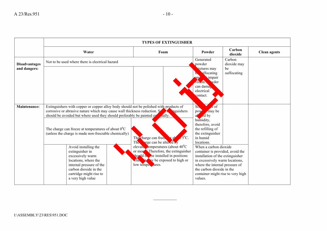
A 23/Res.951 - 10 -
I:\ASSEMBLY\23\RES\951.DOC
TYPES OF EXTINGUISHER
Water Foam Powder Carbon dioxide Clean agents
Not to be used where there is electrical hazard Disadvantages and dangers:
Generated powder mixtures may be suffocating and can impair vision. Powder can damage electrical contact.
Carbon dioxide may be suffocating
Extinguishers with copper or copper alloy body should not be polished with products of corrosive or abrasive nature which may cause wall thickness reduction. Such extinguishers should be avoided but where used they should preferably be painted externally.
The charge can freeze at temperatures of about 00C (unless the charge is made non-freezable chemically)
Some types of powder may be altered by humidity, therefore, avoid the refilling of the extinguisher in humid locations.
Maintenance:
Avoid installing the extinguisher in excessively warm locations, where the internal pressure of the carbon dioxide in the cartridge might rise to a very high value
The charge can freeze at about 50C. The charge can be altered by elevated temperatures (about 400C or more). Therefore, the extinguisher should not be installed in positions where it may be exposed to high or low temperatures.
When a carbon dioxide container is provided, avoid the installation of the extinguisher in excessively warm locations, where the internal pressure of the carbon dioxide in the container might rise to very high values.
__________
Void

I:\CIRC\MSC\01\1312.doc
INTERNATIONAL MARITIME ORGANIZATION 4 ALBERT EMBANKMENT LONDON SE1 7SR Telephone: 020 7735 7611 Fax: 020 7587 3210
IMO
E
Ref. T4/4.01 MSC.1/Circ.1312 10 June 2009
REVISED GUIDELINES FOR THE PERFORMANCE AND TESTING CRITERIA, AND SURVEYS OF FOAM CONCENTRATES FOR
FIXED FIRE-EXTINGUISHING SYSTEMS 1 The Maritime Safety Committee, at its sixtieth session (6 to 10 April 1992), approved Guidelines for the performance and testing criteria, and surveys of low-expansion foam concentrates for fixed fire-extinguishing systems (MSC/Circ.582). 2 The Committee, at its sixty-eighth session (28 May to 6 June 1997), approved Guidelines for the performance and testing criteria, and surveys of expansion foam concentrates for fixed fire-extinguishing systems of chemical tankers (MSC/Circ.799). 3 The Sub-Committee on Fire Protection, at its fifty-third session (16 to 20 February 2009) reviewed the aforementioned Guidelines and made amendments to the test methods for both types of foam concentrates which combined the test procedure into one document. 4 The Committee, at its eighty-sixth session (27 May to 5 June 2009), after having considered the above proposal by the Sub-Committee on Fire Protection, at its fifty-third session, approved the Revised Guidelines for the performance and testing criteria, and surveys of foam concentrates for fixed fire-extinguishing systems, as set out in the annex. 5 Member Governments are invited to apply the annexed Guidelines when approving foam concentrates for fixed fire-extinguishing systems onboard tankers and chemical tankers and bring them to the attention of ship designers, shipowners, equipment manufacturers, test laboratories and other parties concerned. 6 This circular supersedes MSC/Circ.582 and Corr.1, and MSC/Circ.799. Type approvals conducted in accordance with the aforementioned Guidelines should remain valid until 1 July 2012.
***
Attachment 5. to ClassNK Technical Information No.TEC-0970
Void

MSC.1/Circ.1312
I:\CIRC\MSC\01\1312.doc
ANNEX
REVISED GUIDELINES FOR THE PERFORMANCE AND TESTING CRITERIA, AND SURVEYS OF FOAM CONCENTRATES FOR
FIXED FIRE-EXTINGUISHING SYSTEMS 1 GENERAL 1.1 Application These Guidelines apply to the foam concentrates used for fixed deck foam fire-extinguishing systems required for tankers by SOLAS regulations II-2/10.8 and chapter 14 of the International Code for Fire Safety Systems (FSS Code), and chemical tankers as specified by SOLAS regulation II-2/1.6.2.1.2 and the International Code for the Construction and Equipment of Ships Carrying Dangerous Chemicals in Bulk (IBC Code). These Guidelines also apply to foam concentrates for fixed foam fire-extinguishing systems in machinery spaces according to chapter 6 of the FSS Code and to portable foam applicators according to chapter 4 of the FSS Code. These Guidelines do not apply to the foam generating equipment, only the foam concentrate. 1.2 Definitions For the purpose of these Guidelines, the following definitions apply: 1.2.1 Foam (fire fighting) is an aggregate of air filled bubbles formed from an aqueous solution of suitable foam concentrate. 1.2.2 Foam solution is a solution of foam concentrate and water. 1.2.3 Foam concentrate is a liquid which, when mixed with water in the appropriate concentration, gives a foam solution. 1.2.4 Expansion ratio is the ratio of the volume of foam to the volume of foam solution from which it was made. 1.2.5 Spreading coefficient is a measurement of the ability of one liquid to spontaneously spread across another. 1.2.6 25% (50%) drainage time is the time for 25% (50%) of the liquid content of a foam to drain out. 1.2.7 Gentle application is the application of foam to the surface of a liquid fuel via a backboard, tank wall or surface. 1.2.8 Sediment is insoluble particles in the foam concentrate. 1.2.9 Aqueous film-forming foam concentrate (AFF) is a foam concentrate based on a mixture of hydrocarbon and fluorinated surface active agents. 1.2.10 Alcohol–resistant foam concentrate (AR) is a foam concentrate that is resistant to breakdown when applied to the surface of alcohol or other polar solvents.
Void

MSC.1/Circ.1312 ANNEX Page 2
I:\CIRC\MSC\01\1312.doc
1.2.11 Film-forming fluoroprotein foam concentrate (FFFP) is a foam concentrate which has the ability to form an aqueous film on the surface of some hydrocarbons. 1.2.12 Fluoroprotein foam concentrate (FP) is a protein foam concentrate with added fluorinated surface active agents. 1.2.13 Protein foam concentrate (P) is a foam concentrate made from hydrolyzed protein materials. 1.2.14 Synthetic foam concentrate (S) is a foam concentrate based on a mixture of hydrocarbon surface active agents and which may contain fluorocarbons with additional stabilizers. 1.2.15 Type A foam concentrates are alcohol-resistant or multi-purpose foam concentrates. 1.2.16 Type B foam concentrates are all regular type foam concentrates that are not alcohol-resistant, including fluoroprotein and aqueous film-forming (AFF) foam concentrates. 2 SAMPLING PROCEDURE The sampling method should ensure representative samples which should be stored in filled containers. The sample size should be:
.1 2 x 20 l containers (or other standard shipping containers) for type tests (see section 3); and
.2 2 l for periodical controls (see section 4).
3 TESTS FOR TYPE APPROVAL OF FOAM CONCENTRATES For foam concentrate type approval, the tests under paragraphs 3.1 to 3.14 below should be performed by the foam concentrate manufacturer at laboratories acceptable to the Administration. 3.1 Freezing and thawing 3.1.1 Before and after temperature conditioning in accordance with paragraph 3.1.2 below, the foam concentrate should show no visual sign of stratification, non-homogeneity or sedimentation. 3.1.2 Freezing and thawing test:
.1 apparatus: .1 freezing chamber, capable of achieving temperatures required, as stated in
paragraph 3.1.2.2.1 below; .2 polyethylene tube, approximately 10 mm diameter, 400 mm long and
sealed and weighted at one end, with suitable spacers attached. Figure 1 shows a typical form; and
.3 500 ml cylinder, approximately 400 mm high and 65 mm in diameter.
Void

MSC.1/Circ.1312 ANNEX
Page 3
I:\CIRC\MSC\01\1312.doc
.2 procedure:
.1 set the temperature of the freezing chamber to a temperature which is 10ºC below the freezing point of the sample measured in accordance with standard BS 5117, section 1.3 (excluding 5.2 in the standard). To prevent the glass measuring cylinder from breaking, due to expansion of the foam concentrate on freezing, insert the tube into the measuring cylinder, sealed end downward, weighted if necessary to avoid flotation, and the spacers ensuring it remains approximately on the central axis of the cylinder. Place the cylinder with the sample in the chest, cool it and maintain at the required temperature for 24 h. At the end of this period, thaw the sample for not less than 24 h and not more than 96 h in an ambient temperature of 20 to 25ºC;
.2 repeat the procedure described in the above subparagraph three times to
give four cycles of freezing and thawing; and
.3 condition the sample for seven days at 60ºC followed by one day at room temperature. The sample shall then be examined for visual signs of stratification, non-homogeneity or sedimentation.
3.2 Heat stability An unopened 20 l container (or other standard shipping container), as supplied by the manufacturer from a production batch, should be maintained for seven days at 60ºC, followed by one day at room temperature. Following this conditioning, the foam liquid after agitating/stirring will be subjected to the fire test as per subsection 3.9. Only fire tests as per subsection 3.9 should be performed with the heat conditioned sample. 3.3 Sedimentation 3.3.1 Any sediment in the concentrate prepared in accordance with section 2 should be dispersible through a 180 µm sieve, and the percentage volume of sediment should not be more than 0.25% when tested in accordance with paragraph 3.3.2 below. 3.3.2 The test should be carried out as follows:
.1 apparatus: .1 graduated centrifuge tubes; .2 centrifuge operating at 6,000 ± 100 m/s2; .3 180 µm sieve complying with standard ISO 3310-1; and .4 plastic wash bottle. Note: a centrifuge and tubes complying with standard ISO 3734 are suitable; and
Void

MSC.1/Circ.1312 ANNEX Page 4
I:\CIRC\MSC\01\1312.doc
.2 procedure: centrifuge each sample for 10 min. Determine the volume of the sediment and determine the percentage of this volume with respect to the centrifuged sample volume. Wash the contents of the centrifuge tube onto the sieve and check that the sediment can or cannot be dispersed through the sieve by the jet from the plastic wash bottle.
Note: It is possible that the test method is not suitable for some non-Newtonian foam
concentrates. In this case an alternative method, to the satisfaction of the Administration, should be used so that compliance with this requirement can be verified.
3.4 Kinematic viscosity 3.4.1 The test should be carried out according to standard ASTM D 445-86 or ISO 3104. Kinematic viscosity should not exceed 200 mm2/s. 3.4.2 The method for determining viscosity of non-Newtonian foam concentrates or kinematic viscosity exceeding 200 mm2/s should be to the satisfaction of the Administration. A suitable method is described in standard EN 1568. 3.5 pH value The pH of the foam concentrate prepared in accordance with section 2 should be not less than 6 and not more than 9.5 at 20 ± 2ºC. 3.6 Film formation of the foam solution (if applicable) 3.6.1 The spreading coefficient should be determined using the following formula:
S = Tc – Ts - Ti
where:
S is the spreading coefficient; Tc is the surface tension of cyclohexane (N/m); Ts is the surface tension of the foam solution (N/m); Ti is the interfacial tension between the foam solution and cyclohexane (N/m).
Tc, Ts and Ti should be determined according to paragraph 3.6.2 below. The spreading coefficient S should be greater than 0. 3.6.2 Determination of Tc, Ts and Ti
.1 materials:
.1 solution of foam concentrate, at the recommended usage concentration in distilled water complying with standard ISO 3696; and
Void

MSC.1/Circ.1312 ANNEX
Page 5
I:\CIRC\MSC\01\1312.doc
Note: The solution may be made up in a 100 ml volumetric flask using a pipette to measure the foam concentrate.
.2 for Tc and Ti , cyclohexane of purity not less than 99%;
.2 procedures for surface tension: determine Ts at a temperature of 20 ± 2ºC using the
ring or plate method of standard ISO 304; and .3 procedure for interfacial tension: after measuring the surface tension in
accordance with subparagraph .2 above, introduce a layer of cyclohexane at 20 ± 2ºC onto the foam solution, being careful to avoid contact between the ring or plate and the cyclohexane. Wait 6 ± 1 min and measure Ti .
3.7 Expansion ratio 3.7.1 The test should be carried out according to paragraph 3.7.2 with simulated seawater at about 20ºC having the characteristics stated in paragraph 3.7.3. 3.7.2 Determination of the expansion ratio
.1 apparatus: .1 plastic collecting vessel of volume V, known to ± 16 ml, as shown in
figure 2, equipped with a bottom discharge facility; .2 foam collector, as shown in figure 3; and .3 foam making equipment with nozzle, as shown in figure 4, which when tested
with water has a flow rate of 11.4 l/min at a nozzle pressure of 6.3 ± 0.3 bar;
.2 procedure:
.1 check that the pipe work and hose from the foam solution tank to the nozzle is completely full of solution. Set up the nozzle horizontally directly in front of the foam collector with the front of the nozzle 3 ± 0.3 m from the top edge of the collector. Wet the vessel internally and weigh it (W1). Set up the foam equipment and adjust the nozzle pressure to give a flow rate of 11.4 l/min. Discharge the foam and adjust the height of the nozzle so that the discharge strikes the collector centrally. Keep the nozzle horizontal. Stop the foam discharge and rinse all foam from the collector. Check that the foam solution tank is full. Start discharging the foam and after 30 ± 5 s to allow the discharge to stabilize, place the collecting vessel, with the discharge outlet closed, on the collector. As soon as the vessel is full, remove it from the collector, strike the foam surface level with the rim and start the clock. Weigh the vessel (W2);
.2 calculate the expansion E from the equation:
12 WWVE−
=
Void

MSC.1/Circ.1312 ANNEX Page 6
I:\CIRC\MSC\01\1312.doc
in which it is assumed that the density of the foam solution is 1 and where:
V is the vessel volume in ml; W1 is the mass of the empty vessel in grams; W2 is the mass of the full vessel in grams; and
.3 open the drainage facility and collect the foam solution in the measuring
cylinder to measure the 25% drainage time (see paragraph 3.8.1 below). 3.7.3 Simulated sea water may be made up by dissolving in 0.9584 kg of potable water:
25 g Sodium chloride (NaCl); 11 g Magnesium chloride (MgCl2 6 H2O); 1.6 g Calcium chloride (CaCl2 2H2O); 4 g Sodium sulphate (Na2 SO4).
3.8 Drainage time 3.8.1 The drainage time should be determined according to paragraph 3.7.2.3 above, after having determined the expansion ratio. 3.8.2 The test should be carried out with simulated seawater at about 20ºC having the characteristics stated in paragraph 3.7.3 above. 3.9 Fire tests Fire tests should be carried out according to paragraphs 3.9.1 to 3.9.7. Note: The fire tests of this subsection 3.9 are more expensive and time consuming than the other
tests of these Guidelines. It is recommended that fire tests should be carried out at the end of the test programme, so as to avoid the expense of unnecessary testing of foam concentrates which do not comply in other respects.
3.9.1 Environmental conditions:
.1 air temperature 15 ± 5ºC; .2 fuel temperature 17.5 ± 2.5ºC; .3 water temperature 17.5 ± 2.5ºC; .4 foam solution temperature 17.5 ± 2.5ºC; and .5 maximum wind speed 3 m/s in proximity of the fire tray.
Note: If necessary, some form of wind-screen may be used.
Void
MSC.1/Circ.1312 ANNEX
Page 7
I:\CIRC\MSC\01\1312.doc
3.9.2 Observations during the fire test: During the fire test, record the following:
.1 indoor or outdoor test; .2 air temperature; .3 fuel temperature; .4 water temperature; .5 foam solution temperature; .6 wind speed; .7 extinction time; and .8 25% burnback time.
Note: Burnback time may either be determined visually by an experienced person or may be determined from thermal radiation measurements (a suitable method is described in standard EN 1568).
3.9.3 Foam solution:
.1 prepare a foam solution following the recommendations from the supplier for concentration, maximum premix time, compatibility with the test equipment, avoiding contamination by other types of foam, etc; and
.2 the test should be carried out with simulated sea water at about 20ºC having the
characteristics stated in paragraph 3.7.3 above. 3.9.4 Apparatus:
.1 fire tray: square tray with the following dimensions:
area 4.5 m2; depth 200 mm; thickness of steel wall 2.5 mm; with a vertical steel backboard 1 ± 0.05 m high and 1 ± 0.05 m long;
.2 foam making equipment: in accordance with paragraph 3.7.2.1 for type B foam
concentrates. For type A foam concentrates, the foam application rate should be as determined by the manufacturer, up to a total of three nozzles in accordance with paragraph 3.7.2.1;
Void
MSC.1/Circ.1312 ANNEX Page 8
I:\CIRC\MSC\01\1312.doc
.3 burnback pot: circular burnback pot with the following dimensions:
diameter 300 ± 5 mm; height 150 ± 5 mm; thickness of steel wall 2.5 mm.
3.9.5 Fuel 3.9.5.1 For type B foams, use an aliphatic hydrocarbon mixture with physical properties according to the following specification:
distillation range 84ºC to 105ºC; maximum difference between initial and final boiling points 10ºC; maximum aromatic content 1%; density at 15ºC 707.5 ± 2.5 kg/m3; temperature about 20ºC.
Note: Typical fuels meeting this specification are n-heptane and certain solvent fractions
sometimes referred to as commercial heptane. The Administration may require additional fire tests using an additional test fuel. 3.9.5.2 For type A foams, acetone and isopropyl alcohol should be used as the standard test fuels. However, the Administration may require additional fire tests using different test fuels for water-miscible cargoes that require a higher foam application rate than acetone. Impurities for all type A fuels should not exceed 1%. 3.9.6 Test procedure:
.1 place the tray directly on the ground and ensure that it is level. If using heptane, add approximately 90 l of simulated sea water having the characteristics stated in paragraph 3.7.3, and check that the base of the tray is completely covered. Set up the foam nozzle horizontally, about 1 m above the ground in a position where the central part of the foam discharge will strike the centre axis of the backboard, 0.35 ± 0.1 m above the rim of the tray (gentle application). Add 144 ± 5 l of fuel, to give a nominal freeboard of 150 mm. If using acetone or isopropyl alcohol, add 234 ± 5 l of fuel directly into the tray, without water, to give a nominal freeboard of 150 mm;
.2 ignite the tray not more than 5 min after adding the fuel and allow it to burn for a
period of 60 ± 5 s after full involvement of the surface of the fuel, then start foam application; and
Void

MSC.1/Circ.1312 ANNEX
Page 9
I:\CIRC\MSC\01\1312.doc
.3 apply foam for 300 ± 2 s. Stop foam application and after a further 300 ± 10 s place the burnback pot, containing 2 ± 0.1 l of fuel in the centre of the tray and ignite. Visually estimate when 25% of the tray is covered by sustained flames or by “flare up” flames (see Note below), ignoring any faint, barely visible, or transient flames.
Note: During the burnback test, a “flare up” may occur, in which large flames may be
sustained for periods typically from 30 s to 3 min before decreasing in intensity. 3.9.7 Permissible limits:
.1 extinction time: not more than 5 min; and .2 burnback time: not less than 15 min for 25% of the surface.
3.10 Corrosiveness The storage container should be compatible with its foam concentrate throughout the service life of the foam such that the chemical and physical properties of the foam should not deteriorate below the initial values accepted by the Administration. 3.11 Volumic mass According to standard ASTM D 1298-85. 3.12 Batch certificate The foam concentrate should be delivered with a declaration of the main characteristics (sedimentation, pH value, expansion ratio, drainage time and volumetric mass). The declaration should be issued by the maker and will be the basis for the annual condition test. 3.13 Foam concentrate container marking Each foam concentrate container should be marked with complete information needed to identify the liquid and confirm its intended use. As a minimum, the following information should be included:
.1 name and address of manufacturer; .2 product designation; .3 type of foam (synthetic, protein-based, etc.); .4 intended use (regular or alcohol-resistant); .5 batch number and reference to batch certificate; .6 date of manufacture; .7 expiry date;
Void

MSC.1/Circ.1312 ANNEX Page 10
I:\CIRC\MSC\01\1312.doc
.8 reference to test standard and approvals; .9 recommended usage concentration; .10 indication if seawater compatible; .11 maximum and minimum storage temperature; .12 required onboard storage tank materials (steel, stainless steel, FRP, etc.); .13 quantity of foam concentrate; .14 indication of film forming capability; and .15 safety, health and environmental information.
3.14 Reference test and annual periodic re-test for protein-based alcohol-resistant foam
concentrates Protein-based alcohol-resistant foam concentrates should be required to demonstrate manufacturing consistency through an annual small-scale test at a recognized test laboratory. The reference test should be performed at the same time and at the same recognized laboratory as the full-scale test defined in subsection 3.9. The concentrate should be tested according to standards ISO 7203-3 Annex C, EN 1568-4 Annex I, SP Method 2580 or another standard acceptable to the Administration. The reference test and annual test should be carried out to the same standard. The concentrate is deemed to fail the test if the results from the annual small scale test indicate significant changes in the foam quality compared to the reference test. 4 PERIODICAL CONTROLS OF FOAM CONCENTRATES STORED ON BOARD The attention of the Administration is drawn to the fact that particular installation conditions (excessive ambient storage temperature, contamination of the foam concentrate, incomplete filling of the tank, etc.) may lead to an abnormal ageing of the concentrates. For periodical control of foam concentrates, the tests under paragraphs 4.1 to 4.7 should be performed by the shipowner or operator. They should be carried out at laboratories or authorized service suppliers acceptable to the Administration. The deviations in the values obtained by these tests, in respect of those obtained during the type approval tests, should be within the ranges acceptable to the Administration. Tests under paragraphs 4.1, 4.3 and 4.4 should be carried out on samples maintained at 60ºC for 24 h and subsequently cooled to the test temperature. 4.1 Sedimentation According to paragraph 3.3 above.
Void

MSC.1/Circ.1312 ANNEX Page 11
I:\CIRC\MSC\01\1312.doc
4.2 pH value According to paragraph 3.5 above. 4.3 Expansion ratio According to paragraph 3.7 above. 4.4 Drainage time According to paragraph 3.8 above. 4.5 Volumic mass According to paragraph 3.11 above. 4.6 Small scale fire test for protein-based alcohol-resistant foam concentrates According to paragraph 3.14 above. 4.7 Chemical stability test for protein-based alcohol-resistant foam concentrates Protein-based alcohol-resistant foam concentrates should be subjected to a stability test with acetone. A foam solution should be prepared at the approved concentration and gently applied to the surface of a tray containing acetone. The concentrate is deemed to fail the test if the foam solution mixes with the acetone. 5 INTERVALS OF PERIODIC CONTROLS Except for tests in accordance with paragraph 4.7 the first periodical control of foam concentrates should be performed not more than 3 years after being supplied to the ship, and after that, every year. The tests required by paragraph 4.7 should be performed prior to delivery to the ship and annually thereafter. Vo
id

MSC.1/Circ.1312 ANNEX Page 12
I:\CIRC\MSC\01\1312.doc
Figure 1 – Typical form of polyethylene tube
Figure 2 – Collecting vessel for determination of expansion and drainage time
Figure 3 – Foam collector for expansion and drainage measurement Note: Suitable materials for the
collection surface are stainless steel, aluminium, brass or plastics
Void

MSC.1/Circ.1312 ANNEX Page 13
I:\CIRC\MSC\01\1312.doc
Figure 4 – Foam making nozzle
___________
Void

MSC/Circ.798(9 June 1997)
Guidelines for performance and testing criteria andsurveys of medium-expansion concentrates for
fire-extinguishing systems
1 The Maritime Safety Committee, at its sixty-eighth session (28 Mayto 6 June 1997), approved Guidelines for performance and testing criteriaand surveys of medium-expansion foam concentrates for fire-extinguishingsystems, given in the annex.
2 Member Governments are recommended to ensure that tests fortype approval and periodical controls of the medium-expansion foamconcentrates are performed in accordance with the annexed Guidelines.
Annex
Guidelines for performance and testing criteria andsurveys of medium-expansion foam concentrates
for fire-extinguishing systems
1 General
1.1 Application
These Guidelines apply to the foam concentrates for medium-expansionfoam fire-extinguishing systems referred to in SOLAS regulation 11-2/61.
1.2 Definitions
For the purpose of these Guidelines the following definitions apply:
1.2.1 Foam (fire fighting): an aggregate of air filled bubbles formed froman aqueous solution of a suitable foam concentrate.
1.2.2 Foam solution: a solution of foam concentrate and waters.
1.2.3 Foam concentrate: the liquid which, when mixed with water in theappropriate concentration, gives a foam solution.
215
Attachment 6. to ClassNK Technical Information No.TEC-0970
Void

MSC/C/rc.798
1.2.4 Expansion ratio: the ratio of the volume of foam to the volume offoam solution from which it was made.
1.2.5 Spreading coefficient a measurement of the ability of one liquid tospontaneously spread across another.
1.2.6 25% (50%) drainage time: the time for 25% (50%) of the liquidcontent of a foam to drain out.
1.2.7 Gentle application: application of foam to the surface of a liquidfuel via a backboard, tank wall or other surface.
1.2.8 Sediment: insoluble particles in the foam concentrate.
2 Sampling procedure
2.1 The sampling method should ensure representative samples whichshould be stored in filled containers.
2.2 The sample size should be:
.1 30 / for type tests (see section 3); and
.2 2 / for periodical controls (see section 4).
3 Tests for type approval of foam concentrates
For foam concentrate type approval, the tests under 3.1 to 3.10 should beperformed. They should be carried out at laboratories acceptable to theAdministration.
3.1 Freezing and thawing
3.1.1 Before and after temperature conditioning in accordance with3.1.2, the foam concentrate should show no visual sign of stratification,non-homogeneity or sedimentation.
3.1.2 Freezing and thawing test
.1 Apparatus:
.1 freezing chamber, capable of achieving temperaturesrequired as stated in .2.1 below;
.2 polyethylene tube, approximately 10 mm diameter,400 mm long and sealed and weighted at one end,with suitable spacers attached (figure 1 of MSC/Circ.582shows a typical form); and
.3 500 ml cylinder approximately 400 mm high and 65 mmin diameter.
216
Void

MSC/Circ.798
.2 Procedure:
.1 set the temperature of the freezing chamber to atemperature which is 10°C below the freezing point ofthe sample measured in accordance with BS 5117:section 1.3 (excluding 5.2 in the Standard);
To prevent the glass measuring cylinder from breaking,due to expansion of the foam concentrate on freezing,insert the tube into the measuring cylinder, sealed enddownward, weighted if necessary to void floatation, thespacers ensuring it remains approximately on the centralaxis of the cylinder.
Place the sample in the cylinder in the chest, cool andmaintain at the required temperature for 24 h. At the endof this period thaw the sample for not less than 24 h andnot more than 96 h in an ambient temperature range of20°C to 25°C.
.2 repeat .2.1 above three times to give four cycles offreezing and thawing:
.3 examine the sample for stratification and non-homogeneity; and
.4 condition the sample for 7 days at 60°C followed by oneday at room temperature.
3.2 Heat stability
An unopened 20 / container (or other standard shipping container) assupplied by the manufacturer from a production batch should bemaintained for 7 days at 60°C, followed by one day at roomtemperature. Following this conditioning, the foam liquid after agitating/stirring will be subjected to the fire test as per 3.8, and comply with therequirements given in these Guidelines.
3.3 Sedimentation
3.3.1 Any sediment in the concentrate prepared in accordance withsection 2 should be dispersible through a 180 urn sieve, and thepercentage volume of sediment should not be more than 0.25% whentested in accordance with 3.3.2.
3.3.2 The test should be carried out as follows:
.1 Apparatus:
.1 graduated centrifuge tubes;
.2 centrifuge operating at 6,000 + 100 m/s2;
.3 180 (im sieve complying with ISO 3310-1; and
217
Void

MSC/C/rc.798
.4 plastic wash bottle.
Note: A centrifuge and tubes complying with ISO 3734 aresuitable.
.2 Procedure:
Centrifuge each sample for 10 min. Determine the volume ofthe sediment and determine the percentage of this volumewith respect to the centrifuged sample volume. Wash thecontents of the centrifuge tube onto the sieve and check thatthe sediment can or cannot be dispersed through the sieve bythe jet from the plastic wash bottle.
Note: It is possible that the test method is not suitable for somenon-Newtonian foam concentrates. In this case analternative method, to the satisfaction of theAdministration, should be used so that compliancewith this requirement can be verified.
3.4 Kinematic viscosity
3.4.1 The test should be carried out according to ASTM D 445-86 or ISO3104. Kinematic viscosity should not exceed 200 mm2/s.
3.4.2 The method for determining viscosity of non-Newtonian foamconcentrates should be to the satisfaction of the Administration.
3.5 pH value
The pH value of the foam concentrate should be not less than 6 and notmore than 10 at temperature of 20 + 2°C.
3.6 Expansion ratio
3.6.1 The test should be carried out in accordance with 3.6.2 withseawater at about 20°C. Simulated seawater with the characteristics statedunder 3.6.3 may be used. The expansion ratio obtained with the foamgenerators used on board should be consistent with the expansion ratioobtained with the foam generators during the fire test.
3.6.2 Determination of the expansion ratio:
.1 Apparatus:
.1 plastic collecting vessel of volume (V), approximately 200 /and accurately known to + 2 /;
(An example of suitable vessel is given in ISO 7203-2)
.2 medium-expansion foam-making equipment which whentested with water has a flow rate not less than 3 + 0.1 //min at a nozzle pressure of 5 + 0.1 bar.
(An example of suitable apparatus is given in ISO 7203-2).
218
Void
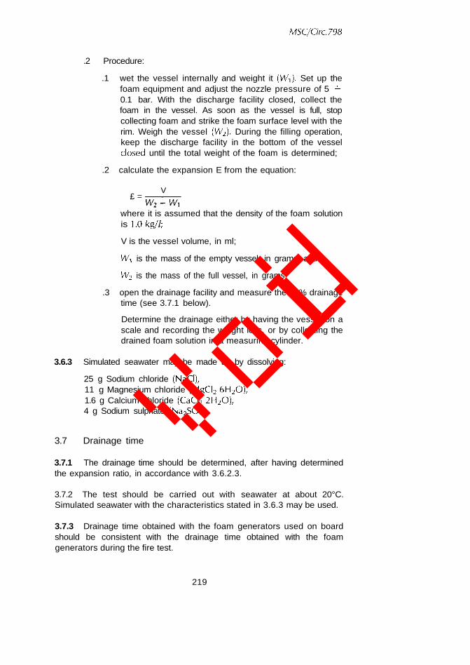
MSC/Grc.798
.2 Procedure:
.1 wet the vessel internally and weight it (Wi). Set up thefoam equipment and adjust the nozzle pressure of 5 +0.1 bar. With the discharge facility closed, collect thefoam in the vessel. As soon as the vessel is full, stopcollecting foam and strike the foam surface level with therim. Weigh the vessel (W2). During the filling operation,keep the discharge facility in the bottom of the vesselclosed until the total weight of the foam is determined;
.2 calculate the expansion E from the equation:
V£ =
where it is assumed that the density of the foam solutionis 1.0kg//;
V is the vessel volume, in ml;
Wi is the mass of the empty vessel, in grams; and
W2 is the mass of the full vessel, in grams;
.3 open the drainage facility and measure the 50% drainagetime (see 3.7.1 below).
Determine the drainage either by having the vessel on ascale and recording the weight loss, or by collecting thedrained foam solution in a measuring cylinder.
3.6.3 Simulated seawater may be made up by dissolving:
25 g Sodium chloride (NaCI),11 g Magnesium chloride (MgCI2 6H2O),1.6 g Calcium chloride (CaCI2 2H2O),4 g Sodium sulphate (Na2SO4).
3.7 Drainage time
3.7.1 The drainage time should be determined, after having determinedthe expansion ratio, in accordance with 3.6.2.3.
3.7.2 The test should be carried out with seawater at about 20°C.Simulated seawater with the characteristics stated in 3.6.3 may be used.
3.7.3 Drainage time obtained with the foam generators used on boardshould be consistent with the drainage time obtained with the foamgenerators during the fire test.
219
Void

MSC/Grc.798
3.8 Fire tests
Fire tests should be carried out in accordance with 3.8.1 to 3.8.7 below.
Note: The fire tests of section 3.8 are more expensive and timeconsuming than the other tests of these Guidelines. It isrecommended that fire tests should be carried out at the endof the test programme, so as to avoid expense ofunnecessary testing of foam concentrates which do notcomply in other respects.
3.8.1 Environmental conditions
.1 Air temperature: 15 + 5°C.
.2 Maximum wind speed: 3 m/s in proximity of the fire tray.
3.8.2 Records
During the fire test, the following should be recorded:
.1 indoor or outdoor test;
.2 air temperature;
.3 fuel temperature:
.4 water temperature;
.5 foam solution temperature;
.6 wind speed; and
.7 extinction time.
3.8.3 Foam solution
.1 Prepare a foam solution, following the recommendations fromthe supplier for concentration, maximum premix time,compatibility with the test equipment, avoidingcontamination by other types of foam, etc.
.2 The test should be carried out with seawater at about 20°C.Simulated seawater with the characteristics stated in 3.6.3 maybe used.
3.8.4 Apparatus
.1 Fire tray:
Circular fire tray of steel with dimensions as follows:
diameter at rim: 1,480 + 15mm
depth: 150 + 10 mm
normal thickness of steel wall: 2.5 mm
Note: The tray has an area of approximately 1.73 m2.
220
Void

MSC/Orc.798
84-105°
10°C
1%
707.5 + 2.5 kg/m3
about 20°C.
.2 Foam-making equipment:
In accordance with subparagraph 3.6.2.1.
3.8.5 Fuel
An aliphatic hydrocarbon mixture with physical properties according to thefollowing specification should be used:
.1 distillation range:
.2 maximum difference betweeninitial and boiling points:
.3 maximum aromatic content:
.4 density at 15°:
.5 temperature:
Note: Typical fuels meeting this specification are n-heptane andcertain solvent fractions sometimes referred to ascommercial heptane.
The Administration may require additional fire tests using an additional testfuel.
3.8.6 Test procedure
3.8.6.1 Place the tray directly on the ground and ensure that it is level.Add approximately 30 / of fresh water and 55 + 2 / o f fuel, to give anominal freeboard of 100 mm.
3.8.6.2 Not later than 5 min after adding of a fuel, ignite the fuel and allowit to burn free for a period of not less than 180 s after the full involvement.Set up the foam equipment at a height which is equal to the upper edge ofthe rim as it is shown at figure 1. 200 + 5 s after full involvement of thesurface into the fire, apply foam along the wall of the tray for a period of120 + 2 s. Record the extinction time as the period from start of foamapplication to extinction.
3.8.7 Permissible limits
Extinction time % not more than 120 s.
3.9 Corrosiveness
The storage container shall be compatible with its foam concentrate,throughout the service life of the foam, such that the chemical and physicalproperties of the foam shall not deteriorate below the initial valuesaccepted by the Administration.
3.10 Volumic mass
According to ASTM D 1298-85.
221
Void

MSC/Circ.798
4 Periodical controls of foam concentrates storedon board
The attention of the Administration is drawn to the fact that particularinstallation conditions (excessive ambient temperature, incomplete filling ofthe tank, etc.) may lead to an abnormal ageing of the concentrates.
For the periodical control of foam concentrate, the tests under 4.1 to 4.5should be performed. They should be carried out at laboratoriesacceptable to the Administration.
The deviations in the values obtained by these tests, in respect of thoseobtained during the type approval tests, should be within rangesacceptable to the Administration.
Tests under 4.1, 4.3 and 4.4 should be carried out on samples maintainedat 60°C for 24 h and subsequently cooled to the test temperature.
4.1 Sedimentation
According to 3.3 above.
4.2 pH value
According to 3.5 above.
4.3 Expansion ratio
According to 3.6 above.
4.4 Drainage time
According to 3.7 above.
4.5 Volumic mass
According to 3.10 above.
5 Intervals of periodical controls
5.1 The first periodical control of foam concentrates stored on boardshould be performed after a period of 3 years and, after that, every year.
5.2 A record of the age of the foam concentrates and of subsequentcontrols should be kept on board.
222
Void

MSC/Grc.798
.B F W
A - pipeB -trayF -fuelW - water
Figure 1 - Fire test arrangement of medium expansion foam
223
Void

Attachment 7. to ClassNK Technical Information No.TEC-0970
Void

Void

Void

Void

Void

Void

Attachment 8. to ClassNK Technical Information No.TEC-0970
Void