Embed Size (px)
DESCRIPTION
Incineration of chlorinated hydrocarbons
Citation preview

Thermal Oxidation for VOC Control
Volatile organic compounds (VOCs) generally are fuels that are easily combustible.Through combustion, which is synomonous with thermal oxidation and incincera-tion, the organic compounds are oxidized to CO
2
and water, while trace elementssuch as sulfur and chlorine are oxidized to species such as SO
2
and HCl.Three combustion processes that control vapor emissions by destroying collected
vapors to prevent release to the environment are (a) thermal oxidation — flares,(b) thermal oxidation and incineration, and (c) catalytic oxidation. Each of theseprocesses has unique advantages and disadvantages that require consideration forproper application. For example, flares are designed for infrequent, large volumesof concentrated hydrocarbon emissions, while thermal oxidizers are designed forhigh-efficiency treatment of continuous, mixed-hydrocarbon gas streams, and cata-lytic oxidizers are designed to minimize fuel costs for continuous, low-concentrationemissions of known composition. The design of the basic processes can be modifiedfor specific applications, resulting in the overlap of the distinctions between pro-cesses. For example, ground flares are basically thermal oxidizers without heatrecovery that frequently are used for intermittent flow of relatively low volumes ofconcentrated VOC streams.
13.1 COMBUSTION BASICS
As every Boy Scout, Girl Scout, and firefighter knows, combustion requires the threelegs of the fire triangle illustrated in Figure 13.1. The oxidizer and fuel composition,i.e., air-to-fuel ratio, is critical to combustion. If the fuel concentration in air is belowthe Lower Flammability Limit (LFL), also known as the Lower Explosive Limit(LEL), the mixture will be too lean to burn. If it is above the Upper FlammabilityLimit (UFL), it will be too rich to burn. Fuels with a wide range of flammabilitylimits burn more easily than those with a narrow range. With a narrow range, theflame is more unstable since the interior of the flame can easily be starved for air.
The heating value of the fuel — the amount of heat released by the combustionprocess — is determined by the heat of combustion and the concentration of thehydrocarbons in the gas stream. Values for the heat of combustion for commonorganic compounds are provided in Table 13.1. The heat of combustion is the sameas the heat of reaction for the oxidation reaction, and therefore can be calculatedfrom the heats of formation of the reactants and products. It is the net chemicalenergy that is released by the oxidation reaction when the reactants begin at 25ºCand after the reaction products are cooled to 25ºC. That the reactants are first heatedto the ignition temperature and the exhaust gases are hot does not affect the value
13
9588ch13 frame Page 191 Wednesday, September 5, 2001 9:55 PM

for the heat of combustion, because the value includes the energy recovered bycooling the exhaust gases. Indeed, the “higher heating value” includes the energyrecovered when water vapor is condensed to liquid at 25ºC, while the lower heatingvalue is based on water remaining in the gaseous state.
The flame temperature is determined by a heat balance including the energyproduced by combustion, absorbed by the reactant gases, released to the exhaustgases, and lost to the surroundings by radiation. Therefore, factors such as thecombustion air temperature, composition of the exhaust gases, and configuration ofthe combustion chamber affect the peak flame temperature.
Despite exposure to flame in the presence of oxygen, not all of a hydrocarbonpollutant will react. The destruction efficiency of VOC pollutants by combustiondepends on the three Ts: temperature (typically 1200 to 2000ºF), time (typically 0.2to 2.0 s at high temperature), and turbulence. The required destruction efficiencyoften is expressed as 9s. Two 9s is 99% destruction efficiency, and five 9s is 99.999%destruction efficiency. Some VOCs burn easily and do not require extremely highdestruction efficiency. Others, especially chlorinated hydrocarbons, do not burn aseasily, and the required high destruction efficiency demands a good combination ofhigh temperatures, adequate residence time at high temperature, and turbulence topromote mixing for good combustion of the entire gas stream. Table 13.2 lists therelative destructability for some common VOCs.
13.2 FLARES
Flaring is a combustion process in which VOCs are piped to a remote location andburned in either an open or an enclosed flame. Flares can be used to control a widevariety of flammable VOC streams, and can handle large fluctuations in VOC con-centration, flow rate, and heating value. The primary advantage of flares is that theyhave a very high turndown ratio and rapid turndown response. With this feature,they can be used for sudden and unexpected large and concentrated flow of hydro-carbons such as safety-valve discharges as well as venting-process upsets, off-specproduct, or waste streams.
FIGURE 13.1
“Fire triangle.”
9588ch13 frame Page 192 Wednesday, September 5, 2001 9:55 PM

Flares cannot be used for dilute VOC streams, less than about 200 BTU/scf,without supplemental fuel because the open flame cannot be sustained. Addingsupplemental fuel, such as natural gas or propane, increases operating cost. Flam-mable gas sensors can be used to regulate supplemental fuel.
TABLE 13.1Heat of Combustion for Various Compounds
CompoundLower Heating Value
(BTU/lb)
Acetaldehyde 10,854Acetone 12,593Acetylene 20,776Ammonia 7992Benzene 17,446Butane 19,697Carbon monoxide 4347Chlorobenzene 11,772Chloroform 1836Cyclohexane 18,818Dichloroethane 4990Ethane 20,432Ethanol 12,022Ethylbenzene 17,779Ethylene 20,295Ethylene dichloride 5221Ethylene glycol 7758Formaldehyde 7603Heptane 19,443Hexane 19,468Hydrogen 51,623Hydrogen sulfide 6545Methane 21,520Methanol 9168Methyl ethyl ketone 13,671Methylene chloride 2264Naphthalene 16,708Octane 19,227Pentane 19,517Phenol 13,688Propane 19,944Propylene 19,691Styrene 17,664Toluene 17,681Trichloroethane 3682Trichloroethylene 3235Vinyl chloride 8136Xylene 17,760
9588ch13 frame Page 193 Wednesday, September 5, 2001 9:55 PM

13.2.1 E
LEVATED
, O
PEN
F
LARE
The commonly known flare is the elevated, open type. Elevated, open flares preventpotentially dangerous conditions at ground level by elevating the open flame aboveworking areas to reduce the effects of noise, heat, smoke, and objectionable odors.The elevated flame burns freely in open air. A simplified flow schematic of anelevated, open flare system is shown in Figure 13.2. The typical system consists of
TABLE 13.2Relative Destructability of VOC Pollutants by Combustion
VOCRelative
Destructability
Alcohols HighAldehydesAromaticsKetonesAcetatesAlkanesChlorinated hydrocarbons Low
FIGURE 13.2
Simplified flare schematic.
9588ch13 frame Page 194 Wednesday, September 5, 2001 9:55 PM

a header to collect waste gases, some form of assist to promote mixing (frequentlysteam is used), and an elevated burner tip with a pilot light. A typical burner tip isshown in Figure 13.3. Atmospheric combustion air is added by turbulence at theburner tip.
Although flares have a very high turndown velocity, exit velocity extremesdetermine the size of the flare tip. Maximum velocities of 60 ft/s and 400 ft/s areused for waste streams with heating values of 300 BTU/scf and 1,000 BTU/scf,respectively, to prevent blowout of the flame. A correlation for maximum velocitywith heating value is provided by Equation 13.1:
(13.1)
whereV
max
= maximum velocity, ft/sB
v
= net heating value, BTU/scf
The design volumetric flow should give 80% of the maximum velocity.
FIGURE 13.3
Steam assisted smokeless flare tip. (Courtesy of Flare Industries, Inc.)
log max10
1214
852V
Bv( ) =+( )
9588ch13 frame Page 195 Wednesday, September 5, 2001 9:55 PM
13.2.2 S
MOKELESS
F
LARE
A
SSIST
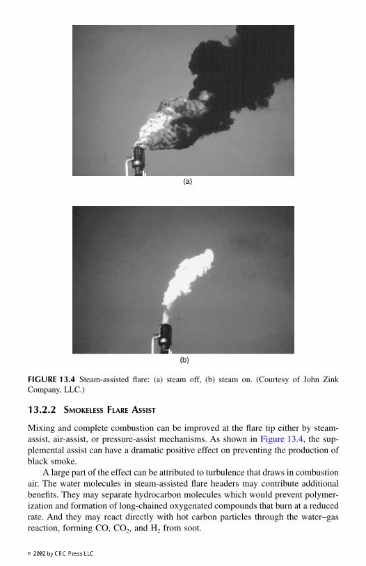
Mixing and complete combustion can be improved at the flare tip either by steam-assist, air-assist, or pressure-assist mechanisms. As shown in Figure 13.4, the sup-plemental assist can have a dramatic positive effect on preventing the production ofblack smoke.
A large part of the effect can be attributed to turbulence that draws in combustionair. The water molecules in steam-assisted flare headers may contribute additionalbenefits. They may separate hydrocarbon molecules which would prevent polymer-ization and formation of long-chained oxygenated compounds that burn at a reducedrate. And they may react directly with hot carbon particles through the water–gasreaction, forming CO, CO
2
, and H
2
from soot.
FIGURE 13.4
Steam-assisted flare: (a) steam off, (b) steam on. (Courtesy of John ZinkCompany, LLC.)
9588ch13 frame Page 196 Wednesday, September 5, 2001 9:55 PM

Steam typically is added at a rate of 0.01 to 0.6 lb steam per lb of vented gas,depending on the carbon content of the flared gas. Typical refinery flares use about0.25 lb steam per lb of vent gas, while many general VOC streams use about 0.4 lbsteam per lb of vent gas. A useful correlation is 0.7 lb steam per lb of CO
2
in the flared gas.Steam assist can produce a loud, high-frequency (above 355 Hz) jet noise in
addition to the noise produced by combustion. Noise is reduced by using multiplesmall jets and by acoustical shrouding.
Air assist is accomplished by using a fan to blow air into an annulus around theflare gas stack center channel. The turbulent air is then mixed at the burner tip. Dueto the fan power requirement, air assist is not economical for high gas volumes, butis useful where steam is not available.
Pressure assist relies on high pressure in the flare header and high pressure dropat the burner tip. This approach cannot be used with variable flow, greatly reducingthe number of viable applications.
13.2.3 F
LARE
H
EIGHT
The required height of an elevated, open flare is determined primarily by limitationon thermal radiation exposure, although luminosity, noise, dispersion of combustionproducts, and dispersion of vented gases during flameout also are considerations.The maximum heat intensity for a very limited exposure period of 8 s is 1500 to2000 BTU/h-ft
2
. This may give one just enough time to seek shelter or quicklyevacuate the area. Most flares are designed for extended exposure at a maximumheat intensity of 500 BTU/h-ft
2
. The distance from the center of the flame to anexposed person is determined using Equation 13.2:
(13.2)
whereD = distance from center of flame, ft
τ
= fraction of radiated heat that is transmitted (assume 1.0, but could be less for smoky or foggy conditions)
F = fraction of heat that is radiated, function of gas composition, burner diameter, and mixing (typical values are 0.1 for H
2
in a small burner to 0.3 for C
4
H
10
in a large burner)
R = net heat release, BTU/hK = allowable radiation, BTU/h-ft
2
The distance from the center of the flame to an exposed person takes into accountnot only the height of the flare tip, but also the length of the flame and the distortionof the flame in windy conditions. The length of the flame is determined by:
(13.3)
where L = flame length, feet
DF R
K2
4= τ
π
log . log .10 100 457 2 04L R= ( ) −
9588ch13 frame Page 197 Wednesday, September 5, 2001 9:55 PM

Elevated flare stacks typically are supported in one of three ways: (1) self-supporting; (2) guy-wires; and (3) derrick. Self-supported stacks tend to be smaller,shorter stacks of about 30 to 100 ft, although stacks of 200 ft or more are possible,depending on soil conditions and the foundation design. Tall stacks can be supportedmore economically with the aid of guy-wires. Gas piping temperature fluctuationsthat cause expansion and contraction must be considered. A derrick structure isrelatively expensive, but can be used to support the load of a very tall stack.
13.2.4 G
ROUND
F
LARE
It is possible to enclose a flare tip with a shroud and bring it down to ground level.In an enclosed ground flare, the burners are contained within an insulated shell. Theshell reduces noise, luminosity, heat radiation, and provides wind protection. Thesedevices also are known as once-through thermal oxidizers without heat recovery.This type of flare often is used for continuous-flow vent streams but can be used forintermittent or variable flow streams when used with turndown and startup/shutdowncontrols. A common application is vapor destruction at fuel loading terminals wherethe vapor flow is intermittent, but predictable.
Enclosed ground flares provide more stable combustion conditions (temperature,residence time, and mixing) than open flares because combustion air addition andmixing is better controlled.
Maintenance is easier because the flare tip is more accessible. But a disadvantageis that ground flares cannot be used in an electrically classified area because it createsan ignition source at ground level.
Temperatures are generally controlled within the range of 1400 to 2000°F usingair dampers. They may use single or multiple burner tips within a refractory-linedsteel shell. Multiple burners allow the number of burners in use to be staged withthe gas flow. Staging can be accomplished by using liquid seal diplegs at differentdepths or by using pressure switches and control valves.
A ground flare enclosure that contains multiple burner tips typically is sized forabout 3 to 4 million BTU per hour per square foot of open area within the refractorylining of the enclosure.
1
The height of the enclosure depends on the flame length,which is a function of a single burner size, rather than the total heat release. A typicalheight for 5 MMBTU/h burner tips is about 32 ft.
13.2.5 S
AFETY
F
EATURES
Flashback protection must be provided to avoid fire or explosion in the flare header.Protection is provided by keeping oxygen out of the flare header using gas seals,water seals, and/or purge gas, and by using flame arrestors and actuated check valves.
Gas seals keep air from mixing with hydrocarbons in the vertical pipe of anelevated flare. Two types of gas seals, a dynamic seal and a density seal, are shownin Figure 13.5.
A density or molecular seal forces gas to travel both up and down to get throughthe seal, like a P-trap water seal, and high-density (high-molecular weight) gascannot rise through low-density gas in the top of the seal. A low purge flow of natural
9588ch13 frame Page 198 Wednesday, September 5, 2001 9:55 PM

gas, less than 1 ft/s, ensures that the gas in the top of the seal is more buoyant thanair, and can keep the oxygen concentration in the stack below 1% with winds up to20 mph. Density seals are recommended in larger flares with tips greater than 36 in.diameter.
2
A dynamic gas seal is designed to provide low resistance to upward flow andhigh resistance to air flowing downward. Natural gas can be used for purge flow atabout 0.04 ft/s to keep the oxygen concentration in the flare stack below 6%. Nitrogenalso can be used as purge gas, and eliminates the possibility of burn-back into theflare tip at low flow rates.
After high-temperature gas is flared, the stack is filled with hot gas that willshrink upon cooling, and that can tend to draw air into the stack. The purge flowcompensates for the reduction in volume, and the required purge rate may begoverned by the rate of cooling during this period.
Flame arrestors and liquid-seal drums also are used to prevent flashback intothe flare header. Liquid-seal drums have the advantage of avoiding the potential forbeing plugged by any liquids that might collect and congeal in the system. And theycan be used as a back-pressure device to maintain positive pressure in the flareheader. A disadvantage is the possibility of freezing if the liquid seal contains water.Steam coils can be used to heat the seal.
Hydrocarbon liquids must be kept out of flare stacks to prevent burning liquiddroplets from being emitted from the stack. Knockout drums are used to separateand collect any liquid droplets larger than about 300 to 600
µ
m before gases aresent to the flare. They may be of either horizontal or vertical design. Generally,knockout drums are designed based on American Petroleum Institute (API) Recom-mended Practices.
3
FIGURE 13.5
Types of gas seals. (Courtesy of Flare Industries, Inc.)
9588ch13 frame Page 199 Wednesday, September 5, 2001 9:55 PM

13.3 INCINERATION
An incinerator, or to be politically correct, a thermal oxidizer, burns VOC-containinggas streams in an enclosed refractory-lined chamber that contains one or moreburners. The incoming waste hydrocarbon vapor can be co-fired with natural gas orpropane to maintain consistently high oxidation temperatures. A ground flare is onetype of incinerator. Discussed below are thermal oxidizers that are designed for highdestruction efficiency with heat recovery built-in to reduce fuel consumption cost.Heat recovery may be achieved with recuperative heat exchangers, with a regener-ative design that employs ceramic beds, or by heating process fluids or generatingsteam.
An advantage of thermal oxidation in an incinerator is the high destructionefficiency that can be obtained by proper control of the combustion chamber designand operation. If temperatures are maintained above 1800°F, greater than 99%hydrocarbon destruction is routinely achievable.
4
This efficiency is due to theincreased residence time, consistently high temperature, and thorough mixing (thethree Ts: time, temperature, and turbulence) in the combustion chamber.
Thermal oxidizers can be costly to install because of required support equipment,including high pressure fuel supplies (for example, natural gas), and substantialprocess-control and monitoring equipment. In addition, public perception of a new“incinerator” can make it difficult to locate and permit a new unit.
13.3.1 R
ECUPERATIVE
T
HERMAL
O
XIDIZER
A recuperative thermal oxidizer uses a shell-and-tube type heat exchanger to recoverheat from the exhaust gas and preheat the incoming process gas, thereby reducingsupplemental fuel consumption. A schematic of a recuperative thermal oxidizer isshown in Figure 13.6. Recuperative heat exchangers with a thermal energy recoveryefficiency of up to 80% are in common commercial use.
13.3.2 R
EGENERATIVE
T
HERMAL
O
XIDIZER
A regenerative thermal oxidizer uses ceramic beds to absorb heat from the exhaustgas and uses the captured heat to preheat the incoming process gas stream. Destruc-tion of VOCs is accomplished in the combustion chamber, which is always fired andkept hot by a separate burner. This system provides very high heat recovery of upto 98%, and can operate with very lean process gas streams because supplementalheat requirements are kept to a minimum with the high heat recovery. The gas steammay contain less than 0.5% VOC, and have a low heat value of less than 10 BTU/scf.
A two-chamber regenerative thermal oxidizer in shown schematically inFigure 13.7. The incoming process gas passes through the warm ceramic bed andis preheated to almost the temperature of the combustion chamber. Figure 13.7 showsa typical inlet gas temperature of 100ºF exiting the first chamber at approximately1430ºF. The combustion chamber provides time, temperature, and turbulence, withthe combusted gases exiting at approximately 100 to 170ºF through the secondceramic bed. Heat is recovered in the second ceramic bed. When the process gasexit temperature reaches approximately 170ºF, valves switch the direction of flow
9588ch13 frame Page 200 Wednesday, September 5, 2001 9:55 PM

so that the incoming gas passes through the freshly warmed bed. By cycling thevalves quickly, as often as every 30 to 120 s, the temperature fluctuation at any pointwithin the bed does not exceed about 70° throughout each cycle. This requires large,
FIGURE 13.6
Recuperative thermal oxidizer flow schematic.
FIGURE 13.7
Two-chamber regenerative flow schematic.
9588ch13 frame Page 201 Wednesday, September 5, 2001 9:55 PM
rapid-cycling valves and extensive ductwork. The valves must be designed for verylow leakage since any leakage contaminates the treated exhaust gases with untreatedprocess gas. Critical high-efficiency systems use zero-leakage valves with an airpurge between double-seal surfaces.
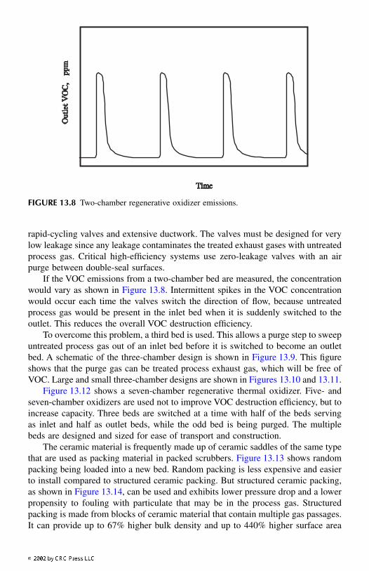
If the VOC emissions from a two-chamber bed are measured, the concentrationwould vary as shown in Figure 13.8. Intermittent spikes in the VOC concentrationwould occur each time the valves switch the direction of flow, because untreatedprocess gas would be present in the inlet bed when it is suddenly switched to theoutlet. This reduces the overall VOC destruction efficiency.
To overcome this problem, a third bed is used. This allows a purge step to sweepuntreated process gas out of an inlet bed before it is switched to become an outletbed. A schematic of the three-chamber design is shown in Figure 13.9. This figureshows that the purge gas can be treated process exhaust gas, which will be free ofVOC. Large and small three-chamber designs are shown in Figures 13.10 and 13.11.
Figure 13.12 shows a seven-chamber regenerative thermal oxidizer. Five- andseven-chamber oxidizers are used not to improve VOC destruction efficiency, but toincrease capacity. Three beds are switched at a time with half of the beds servingas inlet and half as outlet beds, while the odd bed is being purged. The multiplebeds are designed and sized for ease of transport and construction.
The ceramic material is frequently made up of ceramic saddles of the same typethat are used as packing material in packed scrubbers. Figure 13.13 shows randompacking being loaded into a new bed. Random packing is less expensive and easierto install compared to structured ceramic packing. But structured ceramic packing,as shown in Figure 13.14, can be used and exhibits lower pressure drop and a lowerpropensity to fouling with particulate that may be in the process gas. Structuredpacking is made from blocks of ceramic material that contain multiple gas passages.It can provide up to 67% higher bulk density and up to 440% higher surface area
FIGURE 13.8
Two-chamber regenerative oxidizer emissions.
9588ch13 frame Page 202 Wednesday, September 5, 2001 9:55 PM

than random packing, making structured packing a superior heat storage and heattransfer material. Lower pressure drop results from laminar flow through the struc-tured passages. With a superficial inlet velocity of 5.0 ft/s, structured packing pro-vides a pressure drop of about 1.7 in. H
2
O per foot, as compared to approximately5 in. H
2
O per foot of random packing. And the pressure drop variation with flow islinear with structured packing. The lower pressure drop reduces fan power cost orcan be exploited to make a larger ceramic bed for more efficient thermal energyrecovery.
5
FIGURE 13.9
Three-chamber regenerative flow schematic.
FIGURE 13.10
Three-chamber regenerative thermal oxidizer. (Courtesy of Smith Environ-mental Corp.)
9588ch13 frame Page 203 Wednesday, September 5, 2001 9:55 PM

13.3.3 R
ECUPERATIVE
VS
. R
EGENERATIVE
D
ESIGN
S
ELECTION
Recuperative heat recovery tends to be less efficient, but less expensive to install,than regenerative heat recovery. Therefore, it is most economical to use this type ofheat recovery for small systems with more concentrated VOC gas streams that havea high heating value. Once again, the most economical unit is the classic tradeoffof operating vs. capital cost. The cost factors that must be considered include:
• Equipment capital cost• Installation cost• Auxiliary fuel costs, based on thermal efficiency
FIGURE 13.11
Small three-chamber regenerative thermal oxidizer. (Courtesy of Smith Envi-ronmental Corp.)
FIGURE 13.12
Seven-chamber regenerative thermal oxidizer. (Courtesy of Smith Environ-mental Corp.)
9588ch13 frame Page 204 Wednesday, September 5, 2001 9:55 PM

• Fan power, based on pressure drop and gas flow• Maintenance costs, affected by valve cycling and fouling of the heat
exchanger or packing
13.4 CATALYTIC OXIDATION
Like flares and incinerators, catalytic oxidation units destroy hydrocarbon vaporsvia thermal oxidation, but at lower temperatures with the assistance of a catalystthat promotes oxidation. This reduces fuel requirements and operating costs forcatalytic oxidation systems. It also reduces NO
x
emissions from the combustionprocess, and CO emissions are low, too, because CO oxidation is promoted by thecatalyst.
FIGURE 13.13
Loading random media. (Courtesy of Smith Environmental Corp.)
FIGURE 13.14
Installing structured media. (Courtesy of Geoenergy International Corp.)
9588ch13 frame Page 205 Wednesday, September 5, 2001 9:55 PM

Typical operating temperatures of catalytic incinerators range from 400 to 650°Ffor heavy hydrocarbons (C
4
and above), 700 to 1000°F for light hydrocarbons (C
3
andbelow), and 400 to 900°F for halogenated hydrocarbons. Because of the lower oper-ating temperatures, the system enclosure may not require the rugged refractory liningneeded for a high-temperature combustion chamber. Stainless steels are recommendedfor interior surfaces and parts exposed to preheat and oxidizer temperatures.
6
Catalytic oxidation units may incorporate a recuperative heat exchanger for heatrecovery to save additional fuel cost. A typical system consists of a hot gas heatexchanger, a thermal preheat zone with a standard burner, and a catalyst bed asshown in Figure 13.15.
Catalytic incinerators are most effective at treating low concentration vaporstreams, less than one percent by volume, of known composition. Treating higherconcentration vapor streams can overheat and deactivate the catalyst. Dilution of thevapor stream may be required to lower the vapor concentration to below the LELbefore treatment by catalytic oxidation as well as to provide a heat sink to preventoverheating. Mixed hydrocarbon vapors from miscellaneous sources often containsomething that will affect the catalyst, and frequently have highly variable heatingvalues.
Noble metals such as platinum and palladium may be used as catalysts for VOCoxidation. They may be applied to a ceramic or metal substrate with an aluminawashcoat. Metal oxides, including chromia/alumina, cobalt oxide, and copperoxide/manganese oxide also are used. Each type of catalyst has an optimum tem-perature range in which it is effective. Generally, precious metal catalysts are opti-mized for VOC oxidation at higher temperatures than metal oxide catalysts.
FIGURE 13.15
Typical catalytic oxidation system.
9588ch13 frame Page 206 Wednesday, September 5, 2001 9:55 PM
Catalysts supported on a fixed substrate are less susceptible to attrition, thermalshock, and catalyst carryover than catalyst in packed or fluidized beds, and thesubstrate stucture provides relatively low pressure drop, less than 0.5 in. H
2
O perinch of bed depth. Catalyst pellets in packed beds can have a pressure drop of 8 to80 in. H
2
O per inch of bed depth, but allow easy replacement when placed on shallowtrays. Fluidized catalyst beds provide uniform heating and high surface area forcatalyst activity and avoid the potential for catalyst blinding when particulate is inthe process gas.
Precious metal catalysts are sensitive to contaminants in the feed streams andcan be poisoned easily. Lead, zinc, mercury, arsenic, phosphorous, bismuth, anti-mony, iron oxide, and tin are potential poisons to catalysts. Halogens, sulfur com-pounds, and NO
2
are potential chemical inhibitors, although some inhibitors can beremoved by washing with acid or alkaline solutions. Particulate can collect on fixedbed catalyst and blind or mask the active sites. Sometimes compressed air or steamis used to blow off the catalyst surface. Also, heavy hydrocarbons (even in smallamounts) will tend to deposit on fixed catalyst, causing deactivation by masking.Some heavy hydrocarbons and even coke dust can be burned off of the catalystsurface to reactivate it. Eventually, the catalyst will have to be replaced. Typicalcatalyst life can be expected to be 2 to 5 years.
Catalytic oxidation can be used as a “polishing” step, following a recovery unit(e.g., lean oil absorption or other VOC control system) which removes the majorityof the hydrocarbon. Given a constant flow of low-concentration vapor feed material,catalytic incinerators can provide economical high-efficiency VOC destruction.
REFERENCES
1. Leite, O. C., Safety, noise, and emissions elements round out flare guidelines,
OilGas J.
, 24, 68, 1992.2. Leite, O. C., Design alternatives, components key to optimum flares,
Oil Gas J.
, 23,70, 1992.
3. American Petroleum Institute,
Guide for Pressure-Relieving and Depressuring Sys-tems, API Recommended Practice 521
, 4th ed., Washington, D.C., 1997.4. U.S. Environmental Protection Agency,
Handbook — Control Technologies for Haz-ardous Air Pollutants
, EPA-625-6-91-014, Research Triangle Park, NC, 1991.5. Pitts, D. M., Regenerative thermal oxidizers: structured packing improves perfor-
mance,
Chem. Eng.
, 106(1), 113, 1999.6.
Clean Air Compliance Handbook
, Megtec Systems, DePere, WI, 1998.
9588ch13 frame Page 207 Wednesday, September 5, 2001 9:55 PM