Embed Size (px)
Citation preview
VMware Smart Assurance MPLS Manager Configuration Guide
VMware Smart Assurance 10.1.0

You can find the most up-to-date technical documentation on the VMware website at:
https://docs.vmware.com/
VMware, Inc.3401 Hillview Ave.Palo Alto, CA 94304www.vmware.com
Copyright ©
2020 VMware, Inc. All rights reserved. Copyright and trademark information.
VMware Smart Assurance MPLS Manager Configuration Guide
VMware, Inc. 2
Contents
1 Introduction 8Terminology 8
System and device 8
Modeled topology 9
Object 9
MPLS Management Suite installation directory 9
Architectural and functional overview 9
IP Availability Manager 12
Network Protocol Manager for BGP 12
MPLS Manager 13
Global Manager 13
Global Console 14
VMware Smart Assurance Broker 14
VMware Smart Assurance adapters for MPLS Manager 14
VMware Smart Assurance Adapter for Alcatel-Lucent 5620 SAM EMS 14
VMware Smart Assurance MPLS VPN-Tagging Server 16
Configuration roadmap 16
MPLS Manager configuration tasks 17
IP Availability Manager configuration tasks 18
Global Manager configuration tasks 18
What to do after configuration 18
2 Setting Configuration Parameters 20Before you start 20
Configuration directories 21
User configuration parameters 22
Methods for modifying user configuration parameters 23
Editing configuration files to modify configuration parameters 23
Issuing the dmctl command to modify configuration parameters 25
Description of mpls.conf 27
Description of REMOTEPING.conf 38
Description of perl-cli-conf.pl 39
Description of vpn-tagging.conf 41
Adding IP Availability Manager as a source 42
Disabling automatic topology synchronization 43
Prohibiting CLI discovery for certain devices 44
Enabling MPLS-BGP cross-domain correlation 45
Disabling MulticastGroup Impacted events 46
VMware, Inc. 3
Enabling remote ping functionality 47
Changing remote ping global values 48
Configuring the MPLS VPN-Tagging Server 49
Configuring security 50
3 Configuring MPLS Server Interconnections 52Communication links between MPLS component servers 52
Automatically configured communication links 53
Autoconfiguration configuration file: mpls-tma.conf 54
Autoconfiguration operation 56
When the mpls-tma.conf file is loaded 56
How the mpls-tma.conf file is used 56
Automatic link creation for the MPLS Topology Server 57
Automatic link creation for the MPLS Monitoring Server 57
Automatic link creation for the MPLS Analysis Server 58
4 Opening the Global Console 59Global Console overview 59
User accounts and passwords 59
Procedure for opening the Global Console 60
Procedure for opening the Global Manager Administration Console 63
Procedure for opening the Domain Manager Administration Console 63
Procedure for opening the Polling and Thresholds Console 63
5 Configuring IP Availability Manager 64Configuration overview 64
Topology and CLI device-access object import 65
Import of topology 66
Import of CLI device-access objects 66
Types of imported objects 67
About the MPLS topology collection sets 69
Tagged IP object import 70
Overlapping IP addresses 70
IP tagging feature 70
MPLS VPN-Tagging Server 70
CLI discovery, LSP ping, and CLI device-access objects 71
CLI discovery 72
LSP ping 73
CLI device-access objects 74
Enabling and customizing MPLS light discovery 74
Enable MPLS light discovery 74
VMware Smart Assurance MPLS Manager Configuration Guide
VMware, Inc. 4
Specify MPLS device-matching filters 75
Enabling overlapping IP address discovery 75
Enabling interoperability with the MPLS VPN-Tagging Server 76
Creating CLI device-access groups 77
Attach the Polling and Thresholds Console 78
Create CLI device-access groups 78
Enabling BGP light discovery 79
6 Configuring the Global Manager 81Configuration overview 81
About the Global Manager 82
IC Domain Configuration objects 86
IC Domain Configuration creation wizards 86
IC Domain Configuration server reconfiguration 87
Specifying the underlying domains 88
Specifying the underlying domains for configuration scenario 1 89
Specifying the underlying domains for configuration scenario 2 92
Enabling the display of MPLS maps 97
Enabling the use of MPLS remote ping and LSP ping server tools 97
Enabling the subscription of remote ping down and impaired events 100
Changing LSP ping global values 100
Procedure for changing global values in the pinglsp-ondemand.asl file 101
7 Configuring SSH or Telnet Remote Access 103SSH and Telnet overview 103
SSH and Telnet support 103
Client software 104
Client selection 104
SSH1 and SSH2 105
SSH authentication 105
Authentication of the server to the client 105
Authentication of the client to the server 107
SSH client requirements 107
SSH client and SSH server configuration files 108
SSH client configuration 108
Configuring password authentication for the SSH client 109
Configuring public-key authentication for the SSH client 109
SSH server configuration 110
8 Using the Polling and Thresholds Console 112Opening the Polling and Thresholds Console 112
VMware Smart Assurance MPLS Manager Configuration Guide
VMware, Inc. 5
Layout of the Polling and Thresholds Console 113
Polling and Thresholds Console toolbar buttons 114
Understanding groups and settings 114
Working with groups and settings 115
Assign managed objects to groups 116
Modify the properties of a group 116
Add or remove settings 116
Modify the parameters of a setting 117
Modify the priority of groups 117
Edit matching criteria 118
Create new groups 119
9 Configuring Polling and Remote Ping Groups 121Viewing the Polling tab 121
Understanding SNMP polling and periodic remote pings 122
SNMP polling 123
Periodic remote pings 124
SNMP credentials 124
Understanding polling and remote ping groups and settings 125
Modifying polling and remote ping groups 125
Default polling groups and settings 126
ForwarderEndpoints polling group 128
LdpProtocolEndpoint polling group 130
LSP SNMP Setting polling group 131
RsvpProtocolEndpoint polling group 134
VRFs polling group 135
Default remote ping groups and settings 136
CE to CE Pings remote ping group 138
PE to CE Pings remote ping group 139
PE to PE Pings remote ping group 141
PE to Unmanaged CE Pings remote ping group 142
PE to VRF Pings remote ping group 144
System Write Community Strings remote ping group 145
RemotePing External Setting 147
Refresh/calculation interval 148
10 Building CLI-Based Server Tools on the CLI Framework 150CLI tool framework overview 150
CLI-based server tool files 150
CLI-based server-tool development tasks 152
Making the server tool available to console users 152
VMware Smart Assurance MPLS Manager Configuration Guide
VMware, Inc. 6

Global Manager Administration Console method 153
Import XML Configuration server tool method 153
Writing the tool scripts for a CLI-based server tool 154
Tool executable files 156
Local and remote tool scripts 157
GA_Driver 157
Source network device access 160
CLI output text file 162
Server tool log file 163
11 Wildcard Patterns 165Types of wildcard patterns 165
12 SNMP Poller 167SNMP polling overview 167
SNMP poller operation 167
Just-in-time polling 168
Request-consolidation polling 168
13 Configuring a Community String for Juniper Ping MIB Access 169The issue 169
The solution 169
VMware Smart Assurance MPLS Manager Configuration Guide
VMware, Inc. 7
Introduction 1This chapter includes the following topics:
n Terminology
n Architectural and functional overview
n VMware Smart Assurance adapters for MPLS Manager
n VMware Smart Assurance MPLS VPN-Tagging Server
n Configuration roadmap
n What to do after configuration
Terminology
The VMware Smart Assurance MPLS Manager includes the following products:
n VMware Smart Assurance MPLS Manager
n VMware Smart Assurance MPLS VPN-Tagging Server
VMware Smart Assurance MPLS Management Suite is an VMware Smart Assurance Domain Manager. A Domain Manager is a service-assurance application that is associated with a particular type of information-technology domain, such as networks, systems, applications, or application services. For MPLS Manager, the domain is the Multiprotocol Label Switching (MPLS) network and the MPLS virtual private network (VPN). Each Domain Manager is autonomous in the sense that it:
n Maintains its own data models, repository, and problem signatures.
n Monitors and analyzes the discovered objects in its own domain.
System and device
The term “system” is a generic term that represents a computer-based network entity, such as a host, router, or switch. The term “device” has essentially the same meaning as system except that, in some cases, “device” also conveys the sense of specific model, such as a specific model of host, router, or switch.
VMware, Inc. 8
Modeled topology
MPLS Manager uses VMware Smart Assurance object class models to create within its repository instances of MPLS and VPN topology objects, their relationships, and their logical connections. The “modeled topology” mirrors the real topology in the managed network.
Object
The term “object” is intended to have a dual meaning: To simultaneously represent both (1) an VMware Smart Assurance object in the modeled topology and (2) a physical or logical entity in the real topology. An VMware Smart Assurance object corresponds to a physical or logical entity in the real topology.
MPLS Management Suite installation directory
In this document, the term BASEDIR represents the location where VMware Smart Assurance software is installed:
n For UNIX, this location is: /opt/InCharge/<productsuite>.
The <productsuite> represents the VMware Smart Assurance product suite to which the product belongs. For example, on UNIX operating systems, VMware Smart Assurance MPLS Management Suite is, by default, installed to /opt/InCharge/MPLS/smarts.
Optionally, you can specify the root of BASEDIR to be something other than /opt/InCharge (on UNIX).
The VMware Smart Assurance System Administration Guide provides detailed information about the directory structure for VMware Smart Assurance software.
Architectural and functional overview
MPLS Manager, working with VMware Smart Assurance IP Availability Manager and the VMware Smart Assurance Service Assurance Manager (Global Manager), manages MPLS networks and VPNs that are configured and provisioned over MPLS networks. MPLS Manager architecture shows how MPLS Manager interoperates with these components.
VMware Smart Assurance MPLS Manager Configuration Guide
VMware, Inc. 9
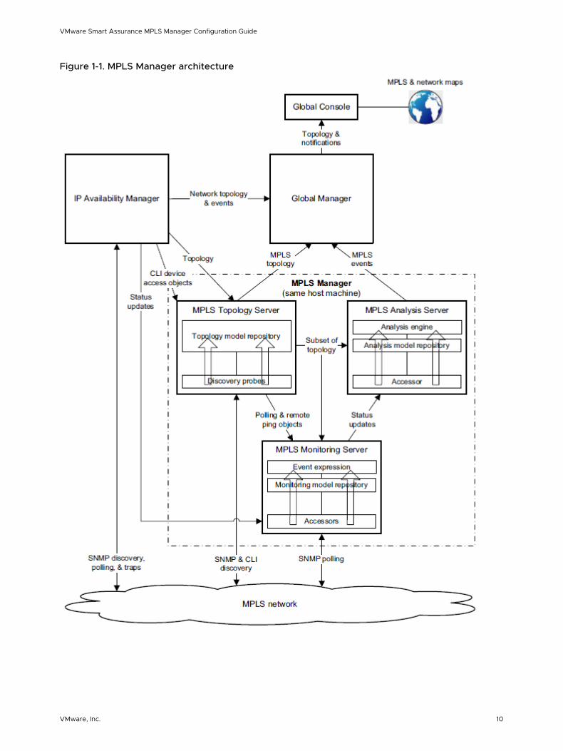
Figure 1-1. MPLS Manager architecture
VMware Smart Assurance MPLS Manager Configuration Guide
VMware, Inc. 10
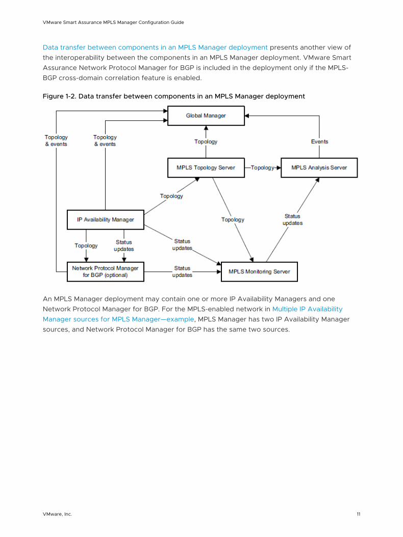
Data transfer between components in an MPLS Manager deployment presents another view of the interoperability between the components in an MPLS Manager deployment. VMware Smart Assurance Network Protocol Manager for BGP is included in the deployment only if the MPLS-BGP cross-domain correlation feature is enabled.
Figure 1-2. Data transfer between components in an MPLS Manager deployment
An MPLS Manager deployment may contain one or more IP Availability Managers and one Network Protocol Manager for BGP. For the MPLS-enabled network in Multiple IP Availability Manager sources for MPLS Manager—example, MPLS Manager has two IP Availability Manager sources, and Network Protocol Manager for BGP has the same two sources.
VMware Smart Assurance MPLS Manager Configuration Guide
VMware, Inc. 11
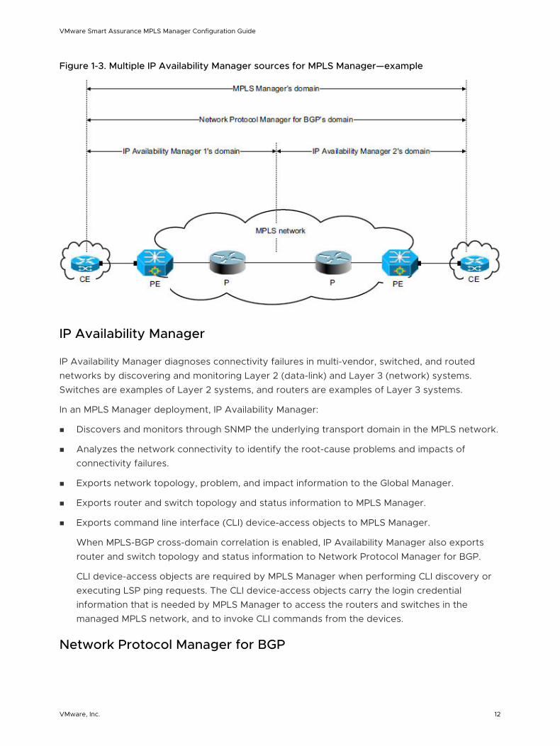
Figure 1-3. Multiple IP Availability Manager sources for MPLS Manager—example
IP Availability Manager
IP Availability Manager diagnoses connectivity failures in multi-vendor, switched, and routed networks by discovering and monitoring Layer 2 (data-link) and Layer 3 (network) systems. Switches are examples of Layer 2 systems, and routers are examples of Layer 3 systems.
In an MPLS Manager deployment, IP Availability Manager:
n Discovers and monitors through SNMP the underlying transport domain in the MPLS network.
n Analyzes the network connectivity to identify the root-cause problems and impacts of connectivity failures.
n Exports network topology, problem, and impact information to the Global Manager.
n Exports router and switch topology and status information to MPLS Manager.
n Exports command line interface (CLI) device-access objects to MPLS Manager.
When MPLS-BGP cross-domain correlation is enabled, IP Availability Manager also exports router and switch topology and status information to Network Protocol Manager for BGP.
CLI device-access objects are required by MPLS Manager when performing CLI discovery or executing LSP ping requests. The CLI device-access objects carry the login credential information that is needed by MPLS Manager to access the routers and switches in the managed MPLS network, and to invoke CLI commands from the devices.
Network Protocol Manager for BGP
VMware Smart Assurance MPLS Manager Configuration Guide
VMware, Inc. 12
Network Protocol Manager for BGP relies on the topology and status updates that are received from IP Availability Manager to discover and monitor BGP networks. On the BGP-enabled devices that are received from IP Availability Manager, Network Protocol Manager for BGP discovers autonomous systems, BGP services, BGP endpoints, BGP sessions that are participating in the routing updates, and BGP configurations.
MPLS Manager
MPLS Manager relies on the topology and status updates that are received from IP Availability Manager to discover and monitor MPLS networks, and to discover and monitor MPLS Layer 2 VPNs (L2VPNs) and Layer 3 VPNs (L3VPNs) that are configured and provisioned over MPLS networks.
When MPLS-BGP cross-domain correlation is enabled, MPLS Manager also relies on the topology that is received from IP Availability Manager to discover the BGP sessions that underlie the discovered MPLS L3VPNs. It also relies on the status updates that are received from Network Protocol Manager for BGP to monitor the discovered BGP sessions.
To improve performance, MPLS Manager is split into the following three components:
n MPLS Topology Server
Imports router and switch topology from IP Availability Manager, discovers the MPLS and VPN topology, and builds a data model of the topology in its repository.
n MPLS Monitoring Server
Imports minimal topology from the MPLS Topology Server, collects status information from IP Availability Manager, and monitors the MPLS network.
n MPLS Analysis Server
Imports minimal topology from the MPLS Topology Server, collects status information from the MPLS Monitoring Server, and performs analysis.
#unique_10/unique_10_Connect_42__MPLS_CONFIG_OVERVIEW_62686 provides information about the MPLS architecture.
Upon importing the initial router and switch topology from IP Availability Manager, the MPLS Topology Server performs its own SNMP and/or CLI discovery to query the routers for MPLS and VPN topology information. Upon building its topology data model, the MPLS Topology Server exports its topology to the Global Manager.
Both the MPLS Monitoring Server and the MPLS Analysis Server load a subset of the discovered topology from the MPLS Topology Server, to serve as the basis for monitoring and analyzing the managed MPLS network. The MPLS Analysis Server exports its analysis results in the form of problem and impact events to the Global Manager.
All MPLS servers in an MPLS Manager deployment run on the same host machine.
Global Manager
VMware Smart Assurance MPLS Manager Configuration Guide
VMware, Inc. 13
The Global Manager integrates the topology, problem, and impact information that is imported from IP Availability Manager and MPLS Manager, and relates the information to services and customers. It also provides cross-domain and end-to-end impact analysis.
The Global Manager displays the topology, problem, and impact information through the Global Console.
Global Console
The Global Console provides a graphical user interface for configuration and administration of Global Managers, Domain Managers, and externally running VMware Smart Assurance adapters.
When the Global Console is attached to the Global Manager, a user can browse the topology in various forms, including maps, and to view notifications about problems that impact availability and performance.
VMware Smart Assurance Broker
The VMware Smart Assurance Broker facilitates Global Console connections to the component applications in an VMware Smart Assurance system deployment.
When a user starts a Global Console process, the process connects to the Broker and launches a dialog box through which the user views and selects any component application that is registered with the Broker. After the user selects an application, the Global Console connects to the application and disconnects from the Broker.
VMware Smart Assurance adapters for MPLS Manager
MPLS Manager works with an optional adapter, the VMware Smart Assurance Adapter for Alcatel-Lucent 5620 SAM EMS.
VMware Smart Assurance Adapter for Alcatel-Lucent 5620 SAM EMS
The VMware Smart Assurance Adapter for Alcatel-Lucent 5620 SAM EMS (the Adapter) collects topology and alarm information from the Alcatel-Lucent 5620 Service Aware Manager (SAM) element management system (EMS), normalizes the information, and delivers the normalized information to the MPLS Topology Server and the MPLS Monitoring Server. An MPLS Manager deployment that includes the Adapter shows the flow of information for the Adapter.
VMware Smart Assurance MPLS Manager Configuration Guide
VMware, Inc. 14
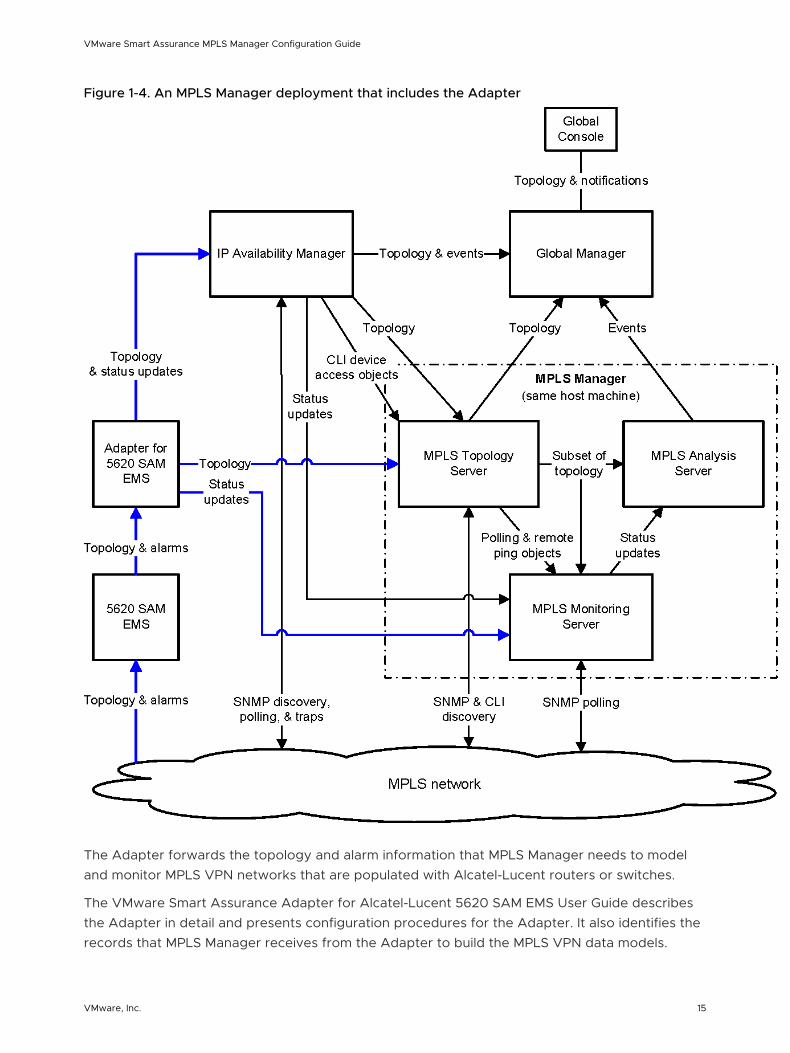
Figure 1-4. An MPLS Manager deployment that includes the Adapter
The Adapter forwards the topology and alarm information that MPLS Manager needs to model and monitor MPLS VPN networks that are populated with Alcatel-Lucent routers or switches.
The VMware Smart Assurance Adapter for Alcatel-Lucent 5620 SAM EMS User Guide describes the Adapter in detail and presents configuration procedures for the Adapter. It also identifies the records that MPLS Manager receives from the Adapter to build the MPLS VPN data models.
VMware Smart Assurance MPLS Manager Configuration Guide
VMware, Inc. 15
VMware Smart Assurance MPLS VPN-Tagging Server
The MPLS VPN-Tagging Server, an optional server in the MPLS Management Suite of products, enables IP Availability Manager to correctly represent in its repository certain overlapping IP-address configurations. Overlapping IP addresses are IP addresses that are reused and configured across multiple network devices in the same managed network environment.
The MPLS VPN-Tagging Server performs overlapping-IP and corresponding network-connection discovery in two vendor-specific environments: Cisco and Alcatel-Lucent. It can perform discovery in both environments at the same time.
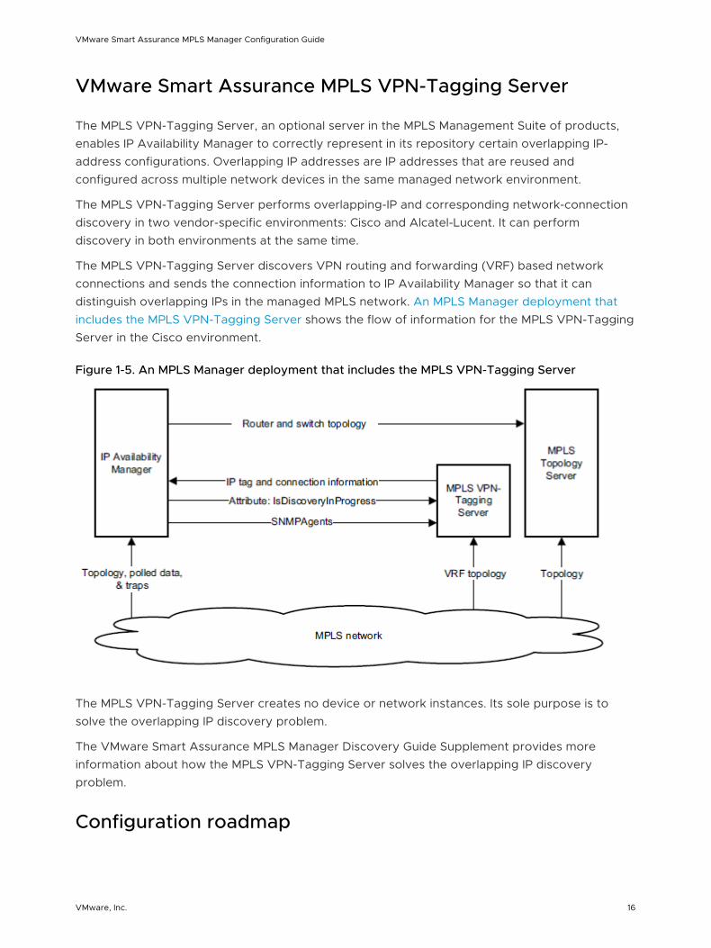
The MPLS VPN-Tagging Server discovers VPN routing and forwarding (VRF) based network connections and sends the connection information to IP Availability Manager so that it can distinguish overlapping IPs in the managed MPLS network. An MPLS Manager deployment that includes the MPLS VPN-Tagging Server shows the flow of information for the MPLS VPN-Tagging Server in the Cisco environment.
Figure 1-5. An MPLS Manager deployment that includes the MPLS VPN-Tagging Server
The MPLS VPN-Tagging Server creates no device or network instances. Its sole purpose is to solve the overlapping IP discovery problem.
The VMware Smart Assurance MPLS Manager Discovery Guide Supplement provides more information about how the MPLS VPN-Tagging Server solves the overlapping IP discovery problem.
Configuration roadmap
VMware Smart Assurance MPLS Manager Configuration Guide
VMware, Inc. 16
The following sections highlight the configuration tasks that are associated with the setup of the application components in an MPLS Manager deployment. These tasks involve configuring the MPLS Manager, IP Availability Manager and Global Manager applications that are part of the deployment.
Some configuration tasks are performed before the applications are started, such as the editing of configuration files, and some are performed through the Global Console when the applications are up and running.
MPLS Manager configuration tasks
Configuring MPLS Manager consists of the following tasks:
n Specify an IP Availability Manager as a source from which MPLS Manager imports MPLS-enabled topology, status updates, and CLI device-access objects (mandatory).
Chapter 2 Setting Configuration Parameters provides information for performing this task.
n Disable automatic topology synchronization with IP Availability Manager (optional).
Chapter 2 Setting Configuration Parameters provides information for performing this task.
n Disable label switched path (LSP), Layer 2 VPN, or Layer 3 VPN discovery (optional).
Chapter 2 Setting Configuration Parameters provides information for performing this task.
n Prohibit CLI discovery for specific devices (optional).
Chapter 2 Setting Configuration Parameters provides information for performing this task.
n Enable MPLS-BGP cross-domain correlation (optional).
Chapter 2 Setting Configuration Parameters provides information for performing this task.
n Disable MulticastGroup Impacted events (optional).
Chapter 2 Setting Configuration Parameters provides information for performing this task.
n Enable remote ping functionality (optional).
Chapter 2 Setting Configuration Parameters provides information for performing this task.
n Change remote ping global values (optional).
Chapter 2 Setting Configuration Parameters provides information for performing this task.
n Configure the MPLS VPN-Tagging Server (optional).
Chapter 2 Setting Configuration Parameters provides information for performing this task.
n Configure a Secure Shell (SSH) client to enable MPLS Manager to perform CLI discovery or to execute LSP ping requests over a secure connection (optional).
Chapter 7 Configuring SSH or Telnet Remote Access provides information for performing this task.
n Customize SNMP polling (optional).
VMware Smart Assurance MPLS Manager Configuration Guide
VMware, Inc. 17
Chapter 9 Configuring Polling and Remote Ping Groups provides information for performing this task.
n Create periodic remote ping instances (optional).
Chapter 9 Configuring Polling and Remote Ping Groups provides information for performing this task.
IP Availability Manager configuration tasks
In addition to performing the configuration and administration tasks that are common to all IP Availability Managers, you perform the following additional tasks to set up IP Availability Manager in an MPLS Manager deployment:
n Enable MPLS light discovery (mandatory in most cases).
n Enable BGP light discovery for MPLS-BGP cross-domain correlation (optional).
n Enable overlapping IP address discovery (optional).
n Enable interoperability with the MPLS VPN-Tagging Server (optional).
n Create CLI device-access objects for MPLS Manager (mandatory).
Chapter 5 Configuring IP Availability Manager provides the procedures for performing these tasks. Procedures for configuring all aspects of IP Availability Manager are given in the VMware Smart Assurance IP Manager User Guide.
Global Manager configuration tasks
In addition to performing the configuration and administration tasks that are common to all Global Managers, you perform the following additional tasks to set up the Global Manager in an MPLS Manager deployment:
n Set up communication links between the Global Manager and the MPLS Manager and IP Availability Manager applications (mandatory).
n Enable access to the MPLS topology maps (optional).
n Enable access to the MPLS remote ping and LSP ping server tools (optional).
n Change LSP ping global values (optional).
Chapter 6 Configuring the Global Manager provides the procedures for performing these tasks. Procedures for configuring all aspects of the Global Manager are given in the VMware Smart Assurance Service Assurance Manager Configuration Guide.
What to do after configuration
Upon configuring your MPLS Manager deployment, you are ready to begin the discovery. To understand, prepare for, and initiate MPLS Manager discovery, consult the VMware Smart Assurance MPLS Manager Discovery Guide Supplement.
VMware Smart Assurance MPLS Manager Configuration Guide
VMware, Inc. 18

After the discovery, consult the VMware Smart Assurance MPLS Management Suite User Guide to understand MPLS Manager monitoring and analysis.
VMware Smart Assurance MPLS Manager Configuration Guide
VMware, Inc. 19
Setting Configuration Parameters 2This chapter includes the following topics:
n Before you start
n Configuration directories
n User configuration parameters
n Methods for modifying user configuration parameters
n Description of mpls.conf
n Description of REMOTEPING.conf
n Description of perl-cli-conf.pl
n Description of vpn-tagging.conf
n Adding IP Availability Manager as a source
n Disabling automatic topology synchronization
n Prohibiting CLI discovery for certain devices
n Enabling MPLS-BGP cross-domain correlation
n Disabling MulticastGroup Impacted events
n Enabling remote ping functionality
n Changing remote ping global values
n Configuring the MPLS VPN-Tagging Server
n Configuring security
Before you start
The configuration procedures in this chapter are based on an MPLS Manager deployment that consists of one MPLS Topology Server, one MPLS Monitoring Server, and one MPLS Analysis Server. In addition, the procedures assume that all three MPLS servers will run on the same host machine, and that all three MPLS servers will be started from the same MPLS Manager installation directory.
VMware, Inc. 20
Many other MPLS Manager deployment configurations are possible. For those configurations, consult VMware Customer Support for additional configuration information.
Configuration directories
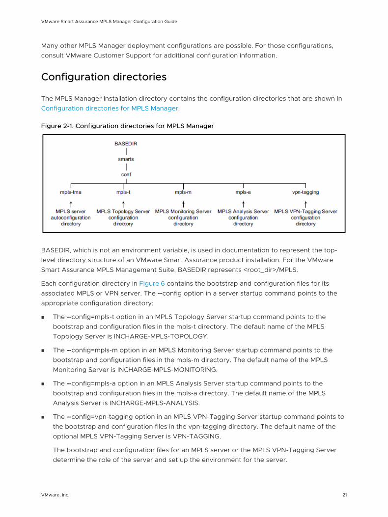
The MPLS Manager installation directory contains the configuration directories that are shown in Configuration directories for MPLS Manager.
Figure 2-1. Configuration directories for MPLS Manager
BASEDIR, which is not an environment variable, is used in documentation to represent the top-level directory structure of an VMware Smart Assurance product installation. For the VMware Smart Assurance MPLS Management Suite, BASEDIR represents <root_dir>/MPLS.
Each configuration directory in Figure 6 contains the bootstrap and configuration files for its associated MPLS or VPN server. The --config option in a server startup command points to the appropriate configuration directory:
n The --config=mpls-t option in an MPLS Topology Server startup command points to the bootstrap and configuration files in the mpls-t directory. The default name of the MPLS Topology Server is INCHARGE-MPLS-TOPOLOGY.
n The --config=mpls-m option in an MPLS Monitoring Server startup command points to the bootstrap and configuration files in the mpls-m directory. The default name of the MPLS Monitoring Server is INCHARGE-MPLS-MONITORING.
n The --config=mpls-a option in an MPLS Analysis Server startup command points to the bootstrap and configuration files in the mpls-a directory. The default name of the MPLS Analysis Server is INCHARGE-MPLS-ANALYSIS.
n The --config=vpn-tagging option in an MPLS VPN-Tagging Server startup command points to the bootstrap and configuration files in the vpn-tagging directory. The default name of the optional MPLS VPN-Tagging Server is VPN-TAGGING.
The bootstrap and configuration files for an MPLS server or the MPLS VPN-Tagging Server determine the role of the server and set up the environment for the server.
VMware Smart Assurance MPLS Manager Configuration Guide
VMware, Inc. 21
User configuration parameters
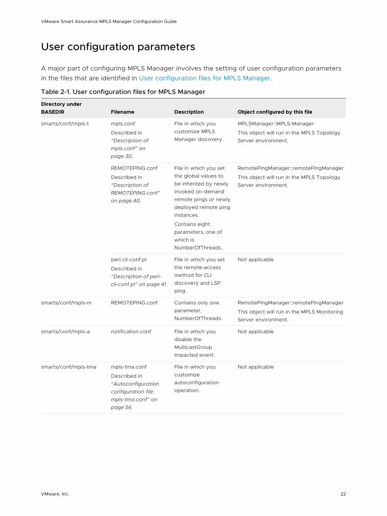
A major part of configuring MPLS Manager involves the setting of user configuration parameters in the files that are identified in User configuration files for MPLS Manager.
Table 2-1. User configuration files for MPLS Manager
Directory under BASEDIR Filename Description Object configured by this file
smarts/conf/mpls-t mpls.conf
Described in “Description of mpls.conf” on page 30.
File in which you customize MPLS Manager discovery.
MPLSManager::MPLS-Manager
This object will run in the MPLS Topology Server environment.
REMOTEPING.conf
Described in “Description of REMOTEPING.conf” on page 40.
File in which you set the global values to be inherited by newly invoked on-demand remote pings or newly deployed remote ping instances.
Contains eight parameters, one of which is NumberOfThreads.
RemotePingManager::remotePingManager
This object will run in the MPLS Topology Server environment.
perl-cli-conf.pl
Described in “Description of perl-cli-conf.pl” on page 41.
File in which you set the remote-access method for CLI discovery and LSP ping.
Not applicable
smarts/conf/mpls-m REMOTEPING.conf Contains only one parameter, NumberOfThreads.
RemotePingManager::remotePingManager
This object will run in the MPLS Monitoring Server environment.
smarts/conf/mpls-a notification.conf File in which you disable the MulticastGroup Impacted event.
Not applicable
smarts/conf/mpls-tma mpls-tma.conf
Described in “Autoconfiguration configuration file: mpls-tma.conf” on page 56.
File in which you customize autoconfiguration operation.
Not applicable
VMware Smart Assurance MPLS Manager Configuration Guide
VMware, Inc. 22
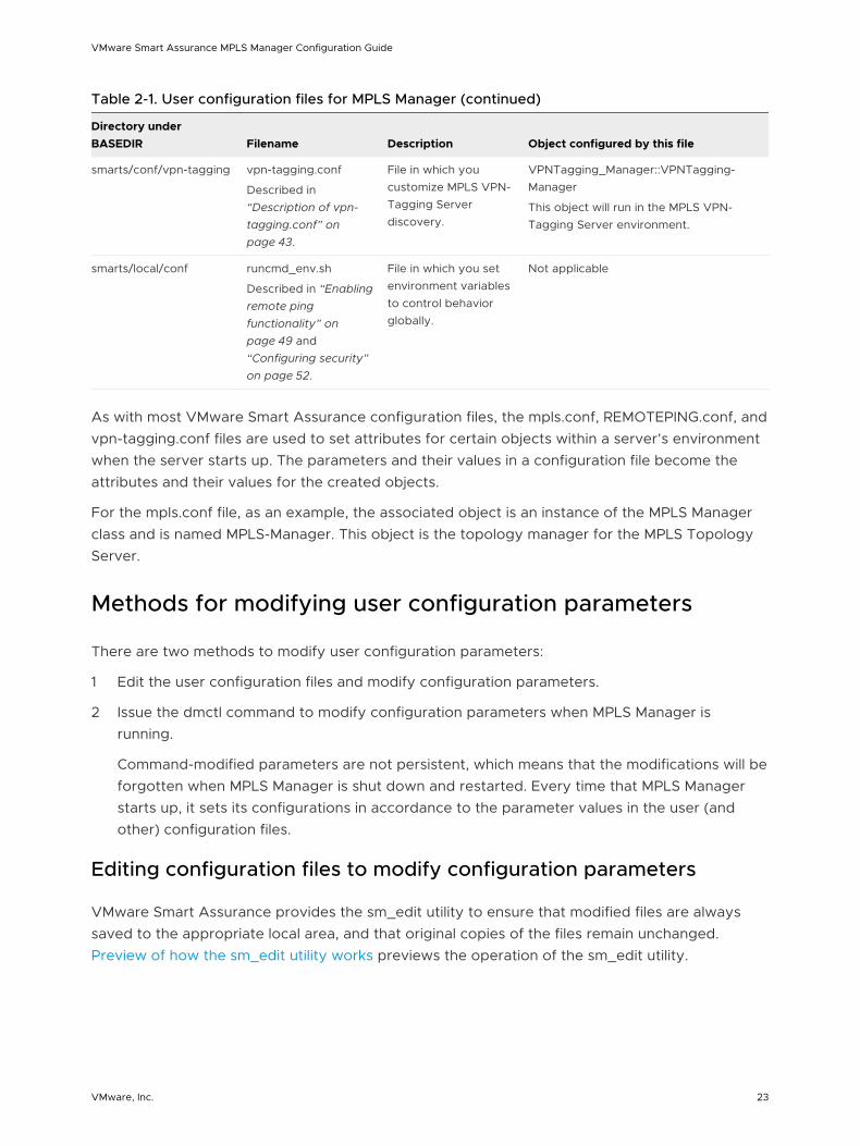
Table 2-1. User configuration files for MPLS Manager (continued)
Directory under BASEDIR Filename Description Object configured by this file
smarts/conf/vpn-tagging vpn-tagging.conf
Described in “Description of vpn-tagging.conf” on page 43.
File in which you customize MPLS VPN-Tagging Server discovery.
VPNTagging_Manager::VPNTagging-Manager
This object will run in the MPLS VPN-Tagging Server environment.
smarts/local/conf runcmd_env.sh
Described in “Enabling remote ping functionality” on page 49 and “Configuring security” on page 52.
File in which you set environment variables to control behavior globally.
Not applicable
As with most VMware Smart Assurance configuration files, the mpls.conf, REMOTEPING.conf, and vpn-tagging.conf files are used to set attributes for certain objects within a server’s environment when the server starts up. The parameters and their values in a configuration file become the attributes and their values for the created objects.
For the mpls.conf file, as an example, the associated object is an instance of the MPLS Manager class and is named MPLS-Manager. This object is the topology manager for the MPLS Topology Server.
Methods for modifying user configuration parameters
There are two methods to modify user configuration parameters:
1 Edit the user configuration files and modify configuration parameters.
2 Issue the dmctl command to modify configuration parameters when MPLS Manager is running.
Command-modified parameters are not persistent, which means that the modifications will be forgotten when MPLS Manager is shut down and restarted. Every time that MPLS Manager starts up, it sets its configurations in accordance to the parameter values in the user (and other) configuration files.
Editing configuration files to modify configuration parameters
VMware Smart Assurance provides the sm_edit utility to ensure that modified files are always saved to the appropriate local area, and that original copies of the files remain unchanged. Preview of how the sm_edit utility works previews the operation of the sm_edit utility.
VMware Smart Assurance MPLS Manager Configuration Guide
VMware, Inc. 23
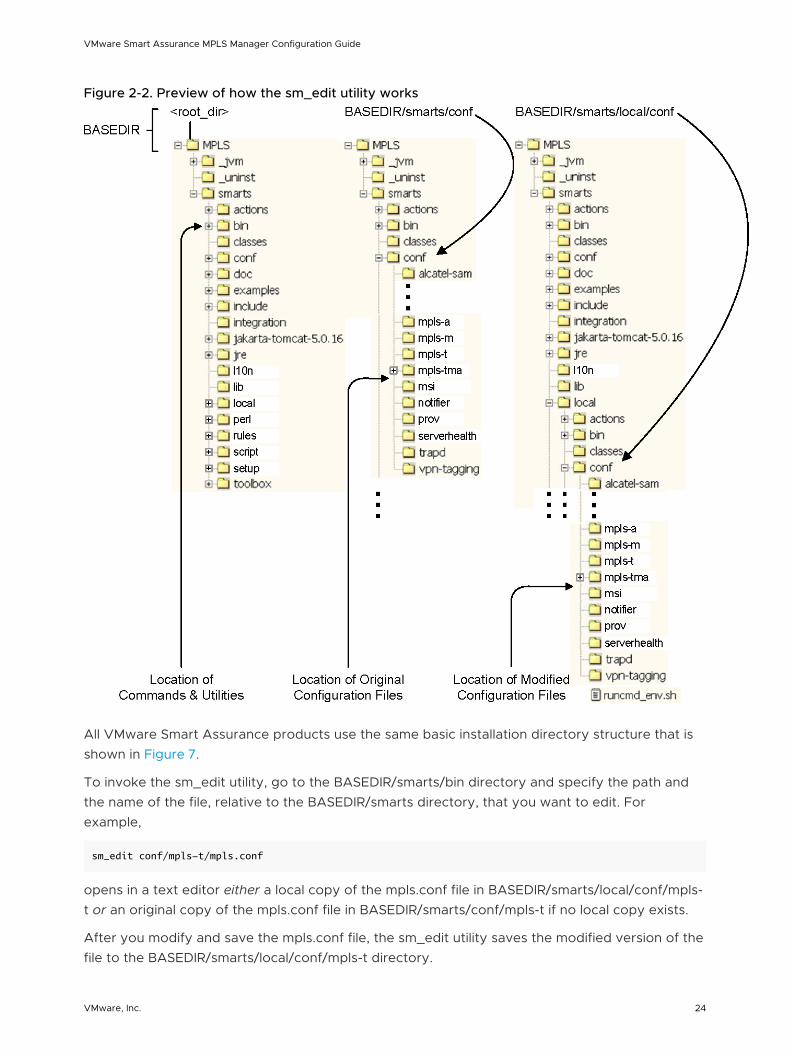
Figure 2-2. Preview of how the sm_edit utility works
All VMware Smart Assurance products use the same basic installation directory structure that is shown in Figure 7.
To invoke the sm_edit utility, go to the BASEDIR/smarts/bin directory and specify the path and the name of the file, relative to the BASEDIR/smarts directory, that you want to edit. For example,
sm_edit conf/mpls-t/mpls.conf
opens in a text editor either a local copy of the mpls.conf file in BASEDIR/smarts/local/conf/mpls-t or an original copy of the mpls.conf file in BASEDIR/smarts/conf/mpls-t if no local copy exists.
After you modify and save the mpls.conf file, the sm_edit utility saves the modified version of the file to the BASEDIR/smarts/local/conf/mpls-t directory.
VMware Smart Assurance MPLS Manager Configuration Guide
VMware, Inc. 24
You can use the sm_edit utility to edit any text file, not just a configuration file, in the BASEDIR/smarts or BASEDIR/smarts/local directory. Because sm_edit assumes a starting point of BASEDIR/smarts, the text-file path that you specify begins with the directory name (conf, rules, script, and so on) under the BASEDIR/smarts directory.
Note Original versions of files may be changed or updated as part of an VMware Smart Assurance software upgrade. However, files located in the BASEDIR/smarts/local directory are retained during an upgrade.
The VMware Smart Assurance System Administration Guide provides additional information about the sm_edit utility.
Issuing the dmctl command to modify configuration parameters
In general, you can use the following dmctl command to change the value of any basic-type attribute (string, boolean, integer, float, and so on) of any VMware Smart Assurance object:
dmctl -s <Domain Manager instance name> put <class::instance::attribute> <value>
Upon issuing a dmctl command, you might be prompted for a username and password. Respond with your user account. For example, to specify the default administrative account, enter username admin and password changeme.
For MPLS Manager, you use the dmctl put command to override parameter settings in the mpls.conf file, the REMOTEPING.conf file, and the vpn-tagging.conf file.
Temporary versus permanent change
The use of the dmctl command to override a parameter value in a configuration file is temporary. When the Domain Manager is restarted, it reads the original parameter value in the configuration file. To make the change permanent, use the sm_edit utility to change the parameter value in the configuration file.
Example 1
As an example of using the dmctl command, you can issue the following dmctl command from the BASEDIR/smarts/bin directory to override the SkipLSPDiscovery parameter value in the mpls.conf file:
dmctl -s INCHARGE-MPLS-TOPOLOGY put
MPLSManager::MPLS-Manager::SkipLSPDiscovery TRUE
The parameters in the mpls.conf file are defined as attributes of the MPLS-Manager object, which is an instance of the MPLSManager class. The MPLS-Manager object is not saved to disk, that is, is not saved to an MPLS Manager repository file in the BASEDIR/smarts/local/repos/icf directory.
Example 2
VMware Smart Assurance MPLS Manager Configuration Guide
VMware, Inc. 25
As another example, you can issue the following dmctl command from the BASEDIR/smarts/bin directory to override the MibStartIndex parameter value in the REMOTEPING.conf file:
dmctl -s INCHARGE-MPLS-TOPOLOGY put
RemotePingManager::remotePingManager::MibStartIndex 2
The parameters in the REMOTEPING.conf file are defined as attributes of the remotePingManager object, which is an instance of the RemotePingManager class. The remotePingManager object is not saved to disk, that is, is not saved to an MPLS Manager repository file.
Example 3
As a final example, you can issue the following dmctl command from the BASEDIR/smarts/bin directory to override the AlcatelDiscoveryInterval parameter value in the vpn-tagging.conf file:
dmctl -s VPN-TAGGING put
VPNTagging_Manager::VPNTagging-Manager::AlcatelDiscoveryInterval
14400
The parameters in the vpn-tagging.conf file are defined as attributes of the VPNTagging-Manager object, which is an instance of the VPNTagging_Manager class. The VPNTagging-Manager object is not saved to disk, that is, is not saved to an MPLS VPN-Tagging Server repository file.
Limitations
Although you can use the dmctl utility to override parameter values in most configuration files, your change might not take effect because a Domain Manager reads some parameters only at startup.
For example, even after you issue the dmctl invoke command to override the StopAutoAMSync setting in the mpls.conf file, your change will not be known to the target MPLS Topology Server until you make the change to the StopAutoAMSync parameter in the mpls.conf file and restart the target server.
Parameter setting changes that require a restart identifies the parameters for which a restart is required. To change a parameter in the table, use the sm_edit utility to modify the parameter’s value in the configuration file, and then restart the affected server or servers to make the change take effect.
Table 2-2. Parameter setting changes that require a restart
Configuration file Parameter Affected server
1 Parameters in this file cannot be overridden by using the dmctl utility; use the sm_edit utility to modify this file.
mpls.conf InChargeDomain::InChargeDomain_INCHARGE-AM {
Type = "AM"
DomainName = "INCHARGE-AM"
DisplayName = "INCHARGE-AM"
}
MPLS Topology Server
VMware Smart Assurance MPLS Manager Configuration Guide
VMware, Inc. 26
Table 2-2. Parameter setting changes that require a restart (continued)
Configuration file Parameter Affected server
InChargeDomain::InChargeDomain_INCHARGE-BGP {
Type = "BGP"
DomainName = "INCHARGE-BGP"
DisplayName = "INCHARGE-BGP"
}
StopAutoAMSync
vpn-tagging.conf InChargeDomain::InChargeDomain_INCHARGE-AM {
Type = "AM"
DomainName = "INCHARGE-AM"
DisplayName = "INCHARGE-AM"
}
MPLS VPN-Tagging Server
perl-cli-conf.pl 1 All MPLS Topology Server
runcmd_env.sh 1 All MPLS Topology Server MPLS Monitoring Server MPLS Analysis Server MPLS VPN-Tagging Server
Description of mpls.conf
The mpls.conf file contains configuration parameters that you edit to customize MPLS Manager discovery. The parameters are a subset of attributes that are defined for the MPLS topology manager (“MPLS-Manager” object) in the MPLS Topology Server environment.
You use the parameters in this file to accomplish such tasks as:
n Disabling the discovery of LSP, Layer 2 VPN, or Layer 3 VPN objects.
n Prohibiting command line interface (CLI) discovery for certain devices.
n Specifying one or more IP Availability Managers as topology sources for the MPLS Topology Server.
n Enabling the MPLS-BGP cross-domain correlation feature.
Each parameter entry in the mpls.conf file is commented-out (preceded with a # character) and is set to its non-default value. To change a parameter to its non-default value, remove the preceding # character from the associated parameter entry.
Parameters in the mpls.conf file describes the parameters in the mpls.conf file. The parameters and their values are case-sensitive.
Note A description of the parameter to enable LSP load balancing discovery follows this table.
VMware Smart Assurance MPLS Manager Configuration Guide
VMware, Inc. 27
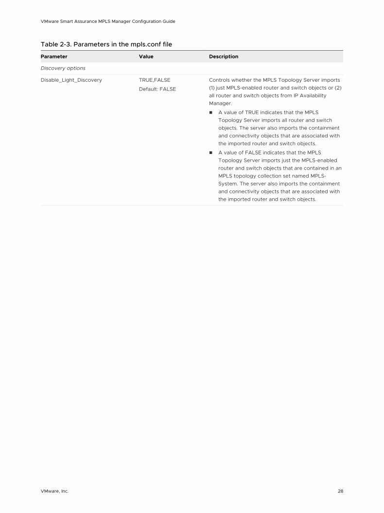
Table 2-3. Parameters in the mpls.conf file
Parameter Value Description
Discovery options
Disable_Light_Discovery TRUE,FALSE
Default: FALSE
Controls whether the MPLS Topology Server imports (1) just MPLS-enabled router and switch objects or (2) all router and switch objects from IP Availability Manager.
n A value of TRUE indicates that the MPLS Topology Server imports all router and switch objects. The server also imports the containment and connectivity objects that are associated with the imported router and switch objects.
n A value of FALSE indicates that the MPLS Topology Server imports just the MPLS-enabled router and switch objects that are contained in an MPLS topology collection set named MPLS-System. The server also imports the containment and connectivity objects that are associated with the imported router and switch objects.
VMware Smart Assurance MPLS Manager Configuration Guide
VMware, Inc. 28
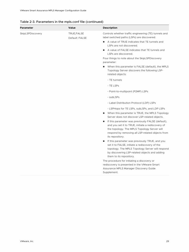
Table 2-3. Parameters in the mpls.conf file (continued)
Parameter Value Description
SkipLSPDiscovery TRUE,FALSE
Default: FALSE
Controls whether traffic engineering (TE) tunnels and label switched paths (LSPs) are discovered.
n A value of TRUE indicates that TE tunnels and LSPs are not discovered.
n A value of FALSE indicates that TE tunnels and LSPs are discovered.
Four things to note about the SkipLSPDiscovery parameter:
n When this parameter is FALSE (default), the MPLS Topology Server discovers the following LSP-related objects:
- TE tunnels
- TE LSPs
- Point-to-multipoint (P2MP) LSPs
- subLSPs
- Label Distribution Protocol (LDP) LSPs
- LSPHops for TE LSPs, subLSPs, and LDP LSPs
n When this parameter is TRUE, the MPLS Topology Server does not discover LSP-related objects.
n If this parameter was previously FALSE (default), and you set it to TRUE, initiate a rediscovery of the topology. The MPLS Topology Server will respond by removing all LSP-related objects from its repository.
n If this parameter was previously TRUE, and you set it to FALSE, initiate a rediscovery of the topology. The MPLS Topology Server will respond by discovering LSP-related objects and adding them to its repository.
The procedure for initiating a discovery or rediscovery is presented in the VMware Smart Assurance MPLS Manager Discovery Guide Supplement.
VMware Smart Assurance MPLS Manager Configuration Guide
VMware, Inc. 29
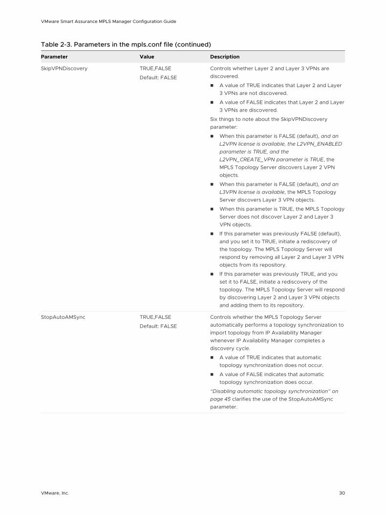
Table 2-3. Parameters in the mpls.conf file (continued)
Parameter Value Description
SkipVPNDiscovery TRUE,FALSE
Default: FALSE
Controls whether Layer 2 and Layer 3 VPNs are discovered.
n A value of TRUE indicates that Layer 2 and Layer 3 VPNs are not discovered.
n A value of FALSE indicates that Layer 2 and Layer 3 VPNs are discovered.
Six things to note about the SkipVPNDiscovery parameter:
n When this parameter is FALSE (default), and an L2VPN license is available, the L2VPN_ENABLED parameter is TRUE, and the L2VPN_CREATE_VPN parameter is TRUE, the MPLS Topology Server discovers Layer 2 VPN objects.
n When this parameter is FALSE (default), and an L3VPN license is available, the MPLS Topology Server discovers Layer 3 VPN objects.
n When this parameter is TRUE, the MPLS Topology Server does not discover Layer 2 and Layer 3 VPN objects.
n If this parameter was previously FALSE (default), and you set it to TRUE, initiate a rediscovery of the topology. The MPLS Topology Server will respond by removing all Layer 2 and Layer 3 VPN objects from its repository.
n If this parameter was previously TRUE, and you set it to FALSE, initiate a rediscovery of the topology. The MPLS Topology Server will respond by discovering Layer 2 and Layer 3 VPN objects and adding them to its repository.
StopAutoAMSync TRUE,FALSE
Default: FALSE
Controls whether the MPLS Topology Server automatically performs a topology synchronization to import topology from IP Availability Manager whenever IP Availability Manager completes a discovery cycle.
n A value of TRUE indicates that automatic topology synchronization does not occur.
n A value of FALSE indicates that automatic topology synchronization does occur.
“Disabling automatic topology synchronization” on page 45 clarifies the use of the StopAutoAMSync parameter.
VMware Smart Assurance MPLS Manager Configuration Guide
VMware, Inc. 30
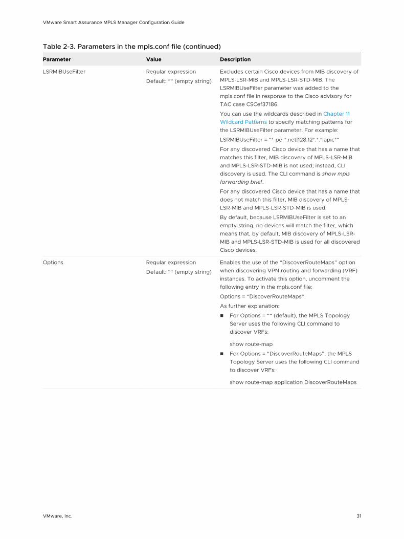
Table 2-3. Parameters in the mpls.conf file (continued)
Parameter Value Description
LSRMIBUseFilter Regular expression
Default: ““ (empty string)
Excludes certain Cisco devices from MIB discovery of MPLS-LSR-MIB and MPLS-LSR-STD-MIB. The LSRMIBUseFilter parameter was added to the mpls.conf file in response to the Cisco advisory for TAC case CSCef37186.
You can use the wildcards described in Chapter 11 Wildcard Patterns to specify matching patterns for the LSRMIBUseFilter parameter. For example:
LSRMIBUseFilter = "*-pe-*.net|128.12*.*.*|apic*"
For any discovered Cisco device that has a name that matches this filter, MIB discovery of MPLS-LSR-MIB and MPLS-LSR-STD-MIB is not used; instead, CLI discovery is used. The CLI command is show mpls forwarding brief.
For any discovered Cisco device that has a name that does not match this filter, MIB discovery of MPLS-LSR-MIB and MPLS-LSR-STD-MIB is used.
By default, because LSRMIBUseFilter is set to an empty string, no devices will match the filter, which means that, by default, MIB discovery of MPLS-LSR-MIB and MPLS-LSR-STD-MIB is used for all discovered Cisco devices.
Options Regular expression
Default: ““ (empty string)
Enables the use of the “DiscoverRouteMaps” option when discovering VPN routing and forwarding (VRF) instances. To activate this option, uncomment the following entry in the mpls.conf file:
Options = “DiscoverRouteMaps”
As further explanation:
n For Options = ““ (default), the MPLS Topology Server uses the following CLI command to discover VRFs:
show route-map
n For Options = “DiscoverRouteMaps”, the MPLS Topology Server uses the following CLI command to discover VRFs:
show route-map application DiscoverRouteMaps
VMware Smart Assurance MPLS Manager Configuration Guide
VMware, Inc. 31
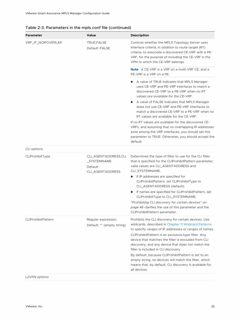
Table 2-3. Parameters in the mpls.conf file (continued)
Parameter Value Description
VRF_IF_NOIPOVERLAP TRUE,FALSE
Default: FALSE
Controls whether the MPLS Topology Server uses interface criteria, in addition to route target (RT) criteria, to associate a discovered CE-VRF with a PE-VRF, for the purpose of including the CE-VRF in the VPN to which the CE-VRF belongs.
Note A CE-VRF is a VRF on a multi-VRF CE, and a PE-VRF is a VRF on a PE.
n A value of TRUE indicates that MPLS Manager uses CE-VRF and PE-VRF interfaces to match a discovered CE-VRF to a PE-VRF when no RT values are available for the CE-VRF.
n A value of FALSE indicates that MPLS Manager does not use CE-VRF and PE-VRF interfaces to match a discovered CE-VRF to a PE-VRF when no RT values are available for the CE-VRF.
If no RT values are available for the discovered CE-VRFs, and assuming that no overlapping IP addresses exist among the VRF interfaces, you should set this parameter to TRUE. Otherwise, you should accept the default.
CLI options
CLIProhibitType CLI_AGENTADDRESS,CLI_SYSTEMNAME
Default: CLI_AGENTADDRESS
Determines the type of filter to use for the CLI filter that is specified for the CLIProhibitPattern parameter; valid values are CLI_AGENTADDRESS and CLI_SYSTEMNAME.
n If IP addresses are specified for CLIProhibitPattern, set CLIProhibitType to CLI_AGENTADDRESS (default).
n If names are specified for CLIProhibitPattern, set CLIProhibitType to CLI_SYSTEMNAME.
“Prohibiting CLI discovery for certain devices” on page 46 clarifies the use of this parameter and the CLIProhibitPattern parameter.
CLIProhibitPattern Regular expression
Default: ““ (empty string)
Prohibits the CLI discovery for certain devices. Use wildcards, described in Chapter 11 Wildcard Patterns to specify ranges of IP addresses or ranges of names.
CLIProhibitPattern is an exclusive-type filter. Any device that matches the filter is excluded from CLI discovery, and any device that does not match the filter is included in CLI discovery.
By default, because CLIProhibitPattern is set to an empty string, no devices will match the filter, which means that, by default, CLI discovery is available for all devices.
L2VPN options
VMware Smart Assurance MPLS Manager Configuration Guide
VMware, Inc. 32
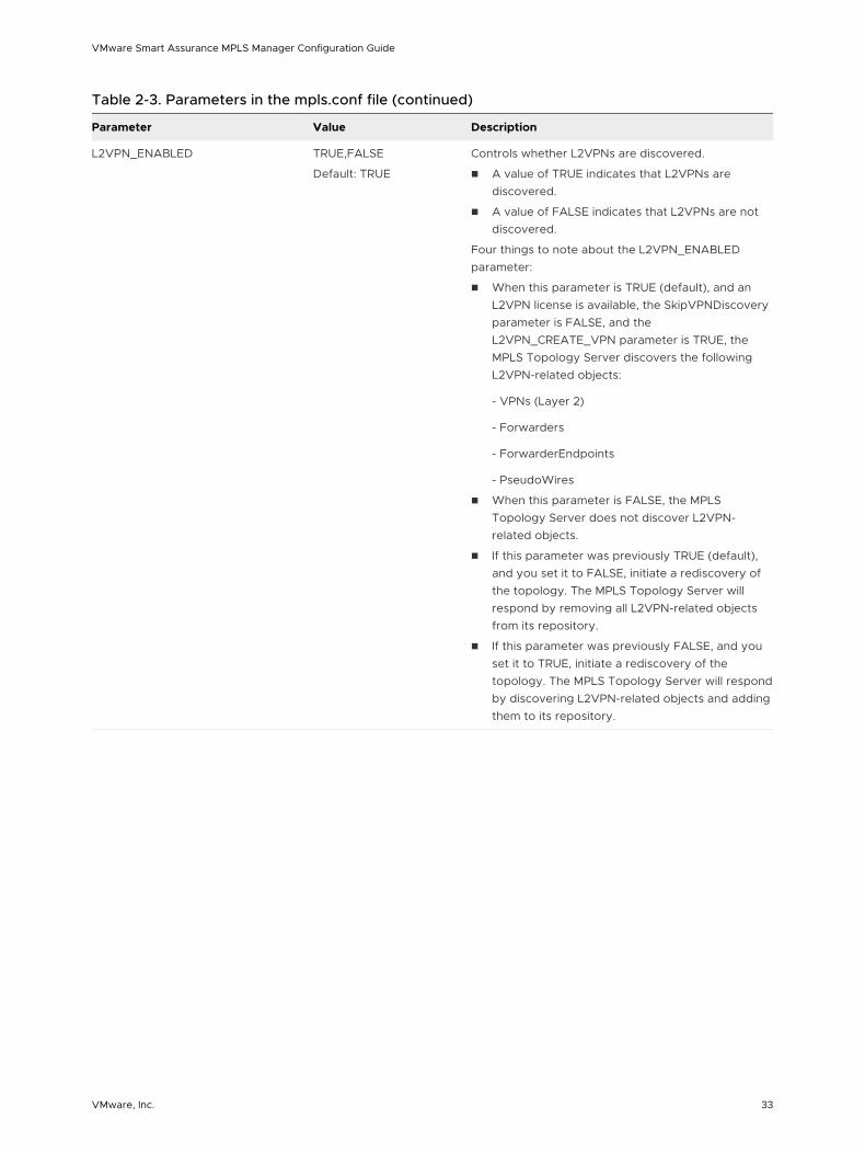
Table 2-3. Parameters in the mpls.conf file (continued)
Parameter Value Description
L2VPN_ENABLED TRUE,FALSE
Default: TRUE
Controls whether L2VPNs are discovered.
n A value of TRUE indicates that L2VPNs are discovered.
n A value of FALSE indicates that L2VPNs are not discovered.
Four things to note about the L2VPN_ENABLED parameter:
n When this parameter is TRUE (default), and an L2VPN license is available, the SkipVPNDiscovery parameter is FALSE, and the L2VPN_CREATE_VPN parameter is TRUE, the MPLS Topology Server discovers the following L2VPN-related objects:
- VPNs (Layer 2)
- Forwarders
- ForwarderEndpoints
- PseudoWires
n When this parameter is FALSE, the MPLS Topology Server does not discover L2VPN-related objects.
n If this parameter was previously TRUE (default), and you set it to FALSE, initiate a rediscovery of the topology. The MPLS Topology Server will respond by removing all L2VPN-related objects from its repository.
n If this parameter was previously FALSE, and you set it to TRUE, initiate a rediscovery of the topology. The MPLS Topology Server will respond by discovering L2VPN-related objects and adding them to its repository.
VMware Smart Assurance MPLS Manager Configuration Guide
VMware, Inc. 33
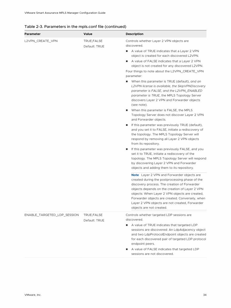
Table 2-3. Parameters in the mpls.conf file (continued)
Parameter Value Description
L2VPN_CREATE_VPN TRUE,FALSE
Default: TRUE
Controls whether Layer 2 VPN objects are discovered.
n A value of TRUE indicates that a Layer 2 VPN object is created for each discovered L2VPN.
n A value of FALSE indicates that a Layer 2 VPN object is not created for any discovered L2VPN.
Four things to note about the L2VPN_CREATE_VPN parameter:
n When this parameter is TRUE (default), and an L2VPN license is available, the SkipVPNDiscovery parameter is FALSE, and the L2VPN_ENABLED parameter is TRUE, the MPLS Topology Server discovers Layer 2 VPN and Forwarder objects (see note).
n When this parameter is FALSE, the MPLS Topology Server does not discover Layer 2 VPN and Forwarder objects.
n If this parameter was previously TRUE (default), and you set it to FALSE, initiate a rediscovery of the topology. The MPLS Topology Server will respond by removing all Layer 2 VPN objects from its repository.
n If this parameter was previously FALSE, and you set it to TRUE, initiate a rediscovery of the topology. The MPLS Topology Server will respond by discovering Layer 2 VPN and Forwarder objects and adding them to its repository.
Note Layer 2 VPN and Forwarder objects are created during the postprocessing phase of the discovery process. The creation of Forwarder objects depends on the creation of Layer 2 VPN objects: When Layer 2 VPN objects are created, Forwarder objects are created. Conversely, when Layer 2 VPN objects are not created, Forwarder objects are not created.
ENABLE_TARGETED_LDP_SESSION TRUE,FALSE
Default: TRUE
Controls whether targeted LDP sessions are discovered.
n A value of TRUE indicates that targeted LDP sessions are discovered: An LdpAdjacency object and two LdpProtocolEndpoint objects are created for each discovered pair of targeted LDP protocol endpoint peers.
n A value of FALSE indicates that targeted LDP sessions are not discovered.
VMware Smart Assurance MPLS Manager Configuration Guide
VMware, Inc. 34
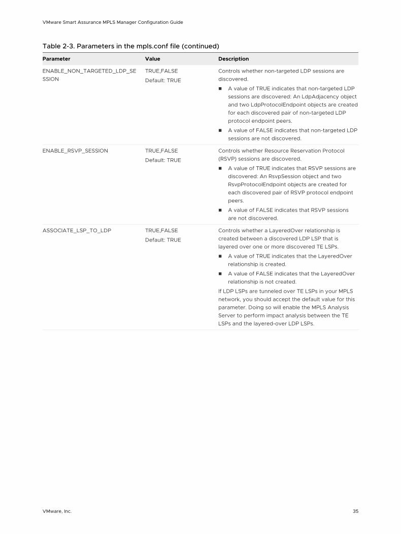
Table 2-3. Parameters in the mpls.conf file (continued)
Parameter Value Description
ENABLE_NON_TARGETED_LDP_SESSION
TRUE,FALSE
Default: TRUE
Controls whether non-targeted LDP sessions are discovered.
n A value of TRUE indicates that non-targeted LDP sessions are discovered: An LdpAdjacency object and two LdpProtocolEndpoint objects are created for each discovered pair of non-targeted LDP protocol endpoint peers.
n A value of FALSE indicates that non-targeted LDP sessions are not discovered.
ENABLE_RSVP_SESSION TRUE,FALSE
Default: TRUE
Controls whether Resource Reservation Protocol (RSVP) sessions are discovered.
n A value of TRUE indicates that RSVP sessions are discovered: An RsvpSession object and two RsvpProtocolEndpoint objects are created for each discovered pair of RSVP protocol endpoint peers.
n A value of FALSE indicates that RSVP sessions are not discovered.
ASSOCIATE_LSP_TO_LDP TRUE,FALSE
Default: TRUE
Controls whether a LayeredOver relationship is created between a discovered LDP LSP that is layered over one or more discovered TE LSPs.
n A value of TRUE indicates that the LayeredOver relationship is created.
n A value of FALSE indicates that the LayeredOver relationship is not created.
If LDP LSPs are tunneled over TE LSPs in your MPLS network, you should accept the default value for this parameter. Doing so will enable the MPLS Analysis Server to perform impact analysis between the TE LSPs and the layered-over LDP LSPs.
VMware Smart Assurance MPLS Manager Configuration Guide
VMware, Inc. 35
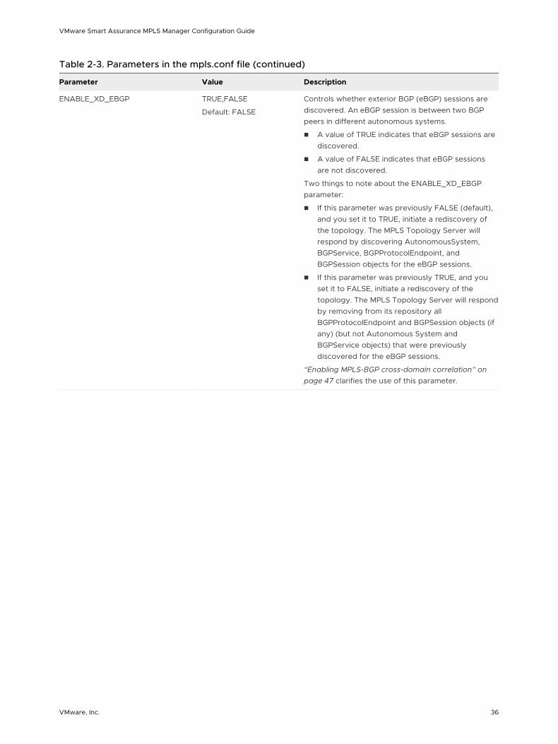
Table 2-3. Parameters in the mpls.conf file (continued)
Parameter Value Description
ENABLE_XD_EBGP TRUE,FALSE
Default: FALSE
Controls whether exterior BGP (eBGP) sessions are discovered. An eBGP session is between two BGP peers in different autonomous systems.
n A value of TRUE indicates that eBGP sessions are discovered.
n A value of FALSE indicates that eBGP sessions are not discovered.
Two things to note about the ENABLE_XD_EBGP parameter:
n If this parameter was previously FALSE (default), and you set it to TRUE, initiate a rediscovery of the topology. The MPLS Topology Server will respond by discovering AutonomousSystem, BGPService, BGPProtocolEndpoint, and BGPSession objects for the eBGP sessions.
n If this parameter was previously TRUE, and you set it to FALSE, initiate a rediscovery of the topology. The MPLS Topology Server will respond by removing from its repository all BGPProtocolEndpoint and BGPSession objects (if any) (but not Autonomous System and BGPService objects) that were previously discovered for the eBGP sessions.
“Enabling MPLS-BGP cross-domain correlation” on page 47 clarifies the use of this parameter.
VMware Smart Assurance MPLS Manager Configuration Guide
VMware, Inc. 36
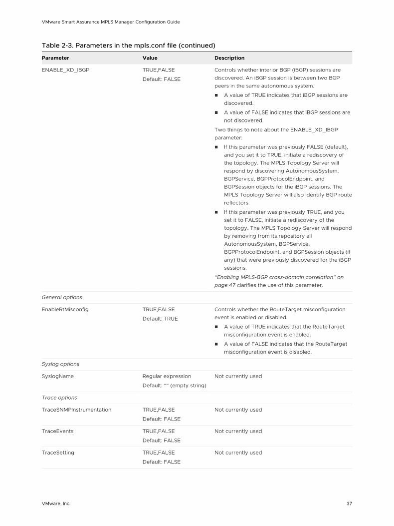
Table 2-3. Parameters in the mpls.conf file (continued)
Parameter Value Description
ENABLE_XD_IBGP TRUE,FALSE
Default: FALSE
Controls whether interior BGP (iBGP) sessions are discovered. An iBGP session is between two BGP peers in the same autonomous system.
n A value of TRUE indicates that iBGP sessions are discovered.
n A value of FALSE indicates that iBGP sessions are not discovered.
Two things to note about the ENABLE_XD_IBGP parameter:
n If this parameter was previously FALSE (default), and you set it to TRUE, initiate a rediscovery of the topology. The MPLS Topology Server will respond by discovering AutonomousSystem, BGPService, BGPProtocolEndpoint, and BGPSession objects for the iBGP sessions. The MPLS Topology Server will also identify BGP route reflectors.
n If this parameter was previously TRUE, and you set it to FALSE, initiate a rediscovery of the topology. The MPLS Topology Server will respond by removing from its repository all AutonomousSystem, BGPService, BGPProtocolEndpoint, and BGPSession objects (if any) that were previously discovered for the iBGP sessions.
“Enabling MPLS-BGP cross-domain correlation” on page 47 clarifies the use of this parameter.
General options
EnableRtMisconfig TRUE,FALSE
Default: TRUE
Controls whether the RouteTarget misconfiguration event is enabled or disabled.
n A value of TRUE indicates that the RouteTarget misconfiguration event is enabled.
n A value of FALSE indicates that the RouteTarget misconfiguration event is disabled.
Syslog options
SyslogName Regular expression
Default: ““ (empty string)
Not currently used
Trace options
TraceSNMPInstrumentation TRUE,FALSE
Default: FALSE
Not currently used
TraceEvents TRUE,FALSE
Default: FALSE
Not currently used
TraceSetting TRUE,FALSE
Default: FALSE
Not currently used
VMware Smart Assurance MPLS Manager Configuration Guide
VMware, Inc. 37
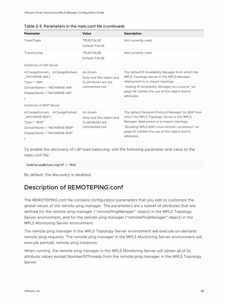
Table 2-3. Parameters in the mpls.conf file (continued)
Parameter Value Description
TraceTraps TRUE,FALSE
Default: FALSE
Not currently used
TraceSyslog TRUE,FALSE
Default: FALSE
Not currently used
Instances of AM Server
InChargeDomain:: InChargeDomain_INCHARGE-AM {
Type = "AM"
DomainName = "INCHARGE-AM"
DisplayName = "INCHARGE-AM"
}
As shown
Note that this object and its attributes are not commented-out.
The default IP Availability Manager from which the MPLS Topology Server in this MPLS Manager deployment is to import topology.
“Adding IP Availability Manager as a source” on page 44 clarifies the use of this object and its attributes.
Instances of BGP Server
InChargeDomain:: InChargeDomain_INCHARGE-BGP {
Type = "BGP"
DomainName = "INCHARGE-BGP"
DisplayName = "INCHARGE-BGP"
}
As shown
Note that this object and its attributes are commented-out.
The default Network Protocol Manager for BGP from which the MPLS Topology Server in this MPLS Manager deployment is to import topology.
“Enabling MPLS-BGP cross-domain correlation” on page 47 clarifies the use of this object and its attributes.
To enable the discovery of LSP load balancing, add the following parameter and value to the mpls.conf file:
EnableLoadBalancingLSP = TRUE
By default, the discovery is disabled.
Description of REMOTEPING.conf
The REMOTEPING.conf file contains configuration parameters that you edit to customize the global values of the remote ping manager. The parameters are a subset of attributes that are defined for the remote ping manager (“remotePingManager” object) in the MPLS Topology Server environment, and for the remote ping manager (“remotePingManager” object) in the MPLS Monitoring Server environment.
The remote ping manager in the MPLS Topology Server environment will execute on-demand remote ping requests. The remote ping manager in the MPLS Monitoring Server environment will execute periodic remote ping instances.
When running, the remote ping manager in the MPLS Monitoring Server will obtain all of its attribute values except NumberOfThreads from the remote ping manager in the MPLS Topology Server.
VMware Smart Assurance MPLS Manager Configuration Guide
VMware, Inc. 38
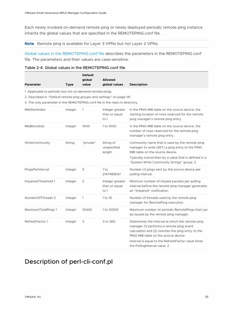
Each newly invoked on-demand remote ping or newly deployed periodic remote ping instance inherits the global values that are specified in the REMOTEPING.conf file.
Note Remote ping is available for Layer 3 VPNs but not Layer 2 VPNs.
Global values in the REMOTEPING.conf file describes the parameters in the REMOTEPING.conf file. The parameters and their values are case-sensitive.
Table 2-4. Global values in the REMOTEPING.conf file
Parameter Type
Default global value
Allowed global values Description
1 Applicable to periodic but not on-demand remote pings.
2 Described in “Default remote ping groups and settings” on page 141.
3 The only parameter in the REMOTEPING.conf file in the mpls-m directory.
MibStartIndex Integer 1 Integer greater than or equal to 1
In the PING MIB table on the source device, the starting location of rows reserved for the remote ping manager’s remote ping entry.
MibBlockSize Integer 1000 1 to 1000 In the PING MIB table on the source device, the number of rows reserved for the remote ping manager’s remote ping entry.
WriteCommunity String “private” String of unspecified length
Community name that is used by the remote ping manager to write (SET) a ping entry to the PING MIB table on the source device.
Typically overwritten by a value that is defined in a “System Write Community Strings” group. 2
PingsPerInterval Integer 5 1 to 2147483647
Number of pings sent by the source device per polling interval.
ImpairedThreshold 1 Integer 2 Integer greater than or equal to 1
Minimum number of missed packets per polling interval before the remote ping manager generates an “Impaired” notification.
NumberOfThreads 3 Integer 1 1 to 10 Number of threads used by the remote ping manager for RemotePing execution.
MaximumTotalPings 1 Integer 10000 1 to 10000 Maximum number of periodic RemotePings that can be issued by the remote ping manager.
RefreshFactor 1 Integer 3 3 to 360 Determines the interval at which the remote ping manager (1) performs a remote ping event calculation and (2) rewrites the ping entry to the PING MIB table on the source device.
Interval is equal to the RefreshFactor value times the PollingInterval value. 2
Description of perl-cli-conf.pl
VMware Smart Assurance MPLS Manager Configuration Guide
VMware, Inc. 39
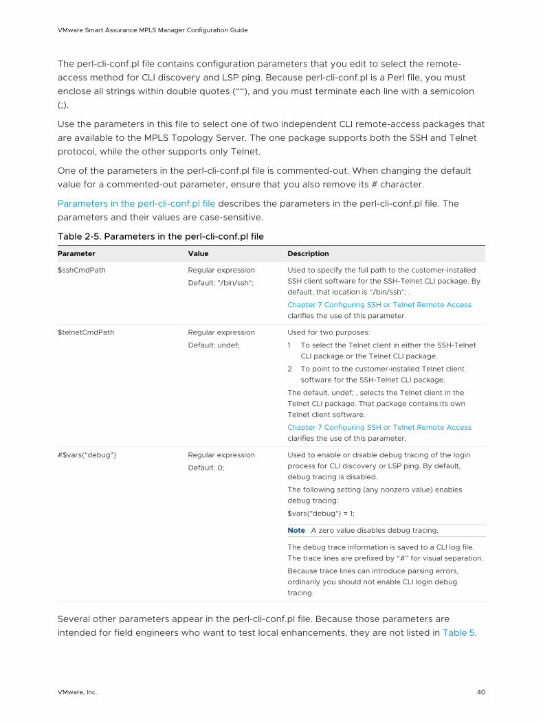
The perl-cli-conf.pl file contains configuration parameters that you edit to select the remote-access method for CLI discovery and LSP ping. Because perl-cli-conf.pl is a Perl file, you must enclose all strings within double quotes (““), and you must terminate each line with a semicolon (;).
Use the parameters in this file to select one of two independent CLI remote-access packages that are available to the MPLS Topology Server. The one package supports both the SSH and Telnet protocol, while the other supports only Telnet.
One of the parameters in the perl-cli-conf.pl file is commented-out. When changing the default value for a commented-out parameter, ensure that you also remove its # character.
Parameters in the perl-cli-conf.pl file describes the parameters in the perl-cli-conf.pl file. The parameters and their values are case-sensitive.
Table 2-5. Parameters in the perl-cli-conf.pl file
Parameter Value Description
$sshCmdPath Regular expression
Default: "/bin/ssh";
Used to specify the full path to the customer-installed SSH client software for the SSH-Telnet CLI package. By default, that location is “/bin/ssh”; .
Chapter 7 Configuring SSH or Telnet Remote Access clarifies the use of this parameter.
$telnetCmdPath Regular expression
Default: undef;
Used for two purposes:
1 To select the Telnet client in either the SSH-Telnet CLI package or the Telnet CLI package.
2 To point to the customer-installed Telnet client software for the SSH-Telnet CLI package.
The default, undef; , selects the Telnet client in the Telnet CLI package. That package contains its own Telnet client software.
Chapter 7 Configuring SSH or Telnet Remote Access clarifies the use of this parameter.
#$vars{"debug"} Regular expression
Default: 0;
Used to enable or disable debug tracing of the login process for CLI discovery or LSP ping. By default, debug tracing is disabled.
The following setting (any nonzero value) enables debug tracing:
$vars{"debug"} = 1;
Note A zero value disables debug tracing.
The debug trace information is saved to a CLI log file. The trace lines are prefixed by “#” for visual separation.
Because trace lines can introduce parsing errors, ordinarily you should not enable CLI login debug tracing.
Several other parameters appear in the perl-cli-conf.pl file. Because those parameters are intended for field engineers who want to test local enhancements, they are not listed in Table 5.
VMware Smart Assurance MPLS Manager Configuration Guide
VMware, Inc. 40
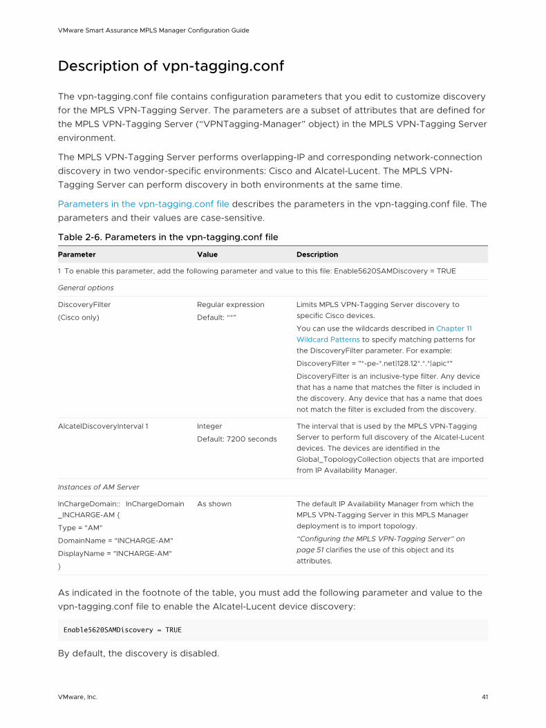
Description of vpn-tagging.conf
The vpn-tagging.conf file contains configuration parameters that you edit to customize discovery for the MPLS VPN-Tagging Server. The parameters are a subset of attributes that are defined for the MPLS VPN-Tagging Server (“VPNTagging-Manager” object) in the MPLS VPN-Tagging Server environment.
The MPLS VPN-Tagging Server performs overlapping-IP and corresponding network-connection discovery in two vendor-specific environments: Cisco and Alcatel-Lucent. The MPLS VPN-Tagging Server can perform discovery in both environments at the same time.
Parameters in the vpn-tagging.conf file describes the parameters in the vpn-tagging.conf file. The parameters and their values are case-sensitive.
Table 2-6. Parameters in the vpn-tagging.conf file
Parameter Value Description
1 To enable this parameter, add the following parameter and value to this file: Enable5620SAMDiscovery = TRUE
General options
DiscoveryFilter
(Cisco only)
Regular expression
Default: “*”
Limits MPLS VPN-Tagging Server discovery to specific Cisco devices.
You can use the wildcards described in Chapter 11 Wildcard Patterns to specify matching patterns for the DiscoveryFilter parameter. For example:
DiscoveryFilter = "*-pe-*.net|128.12*.*.*|apic*"
DiscoveryFilter is an inclusive-type filter. Any device that has a name that matches the filter is included in the discovery. Any device that has a name that does not match the filter is excluded from the discovery.
AlcatelDiscoveryInterval 1 Integer
Default: 7200 seconds
The interval that is used by the MPLS VPN-Tagging Server to perform full discovery of the Alcatel-Lucent devices. The devices are identified in the Global_TopologyCollection objects that are imported from IP Availability Manager.
Instances of AM Server
InChargeDomain:: InChargeDomain_INCHARGE-AM {
Type = "AM"
DomainName = "INCHARGE-AM"
DisplayName = "INCHARGE-AM"
}
As shown The default IP Availability Manager from which the MPLS VPN-Tagging Server in this MPLS Manager deployment is to import topology.
“Configuring the MPLS VPN-Tagging Server” on page 51 clarifies the use of this object and its attributes.
As indicated in the footnote of the table, you must add the following parameter and value to the vpn-tagging.conf file to enable the Alcatel-Lucent device discovery:
Enable5620SAMDiscovery = TRUE
By default, the discovery is disabled.
VMware Smart Assurance MPLS Manager Configuration Guide
VMware, Inc. 41
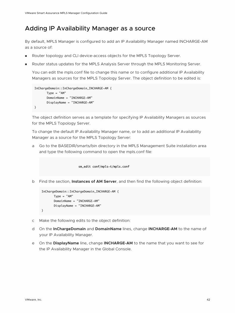
Adding IP Availability Manager as a source
By default, MPLS Manager is configured to add an IP Availability Manager named INCHARGE-AM as a source of:
n Router topology and CLI device-access objects for the MPLS Topology Server.
n Router status updates for the MPLS Analysis Server through the MPLS Monitoring Server.
You can edit the mpls.conf file to change this name or to configure additional IP Availability Managers as sources for the MPLS Topology Server. The object definition to be edited is:
InChargeDomain::InChargeDomain_INCHARGE-AM {
Type = "AM"
DomainName = "INCHARGE-AM"
DisplayName = "INCHARGE-AM"
}
The object definition serves as a template for specifying IP Availability Managers as sources for the MPLS Topology Server.
To change the default IP Availability Manager name, or to add an additional IP Availability Manager as a source for the MPLS Topology Server:
a Go to the BASEDIR/smarts/bin directory in the MPLS Management Suite installation area and type the following command to open the mpls.conf file:
sm_edit conf/mpls-t/mpls.conf
b Find the section, Instances of AM Server, and then find the following object definition:
InChargeDomain::InChargeDomain_INCHARGE-AM {
Type = "AM"
DomainName = "INCHARGE-AM"
DisplayName = "INCHARGE-AM"
}
c Make the following edits to the object definition:
d On the InChargeDomain and DomainName lines, change INCHARGE-AM to the name of your IP Availability Manager.
e On the DisplayName line, change INCHARGE-AM to the name that you want to see for the IP Availability Manager in the Global Console.
VMware Smart Assurance MPLS Manager Configuration Guide
VMware, Inc. 42
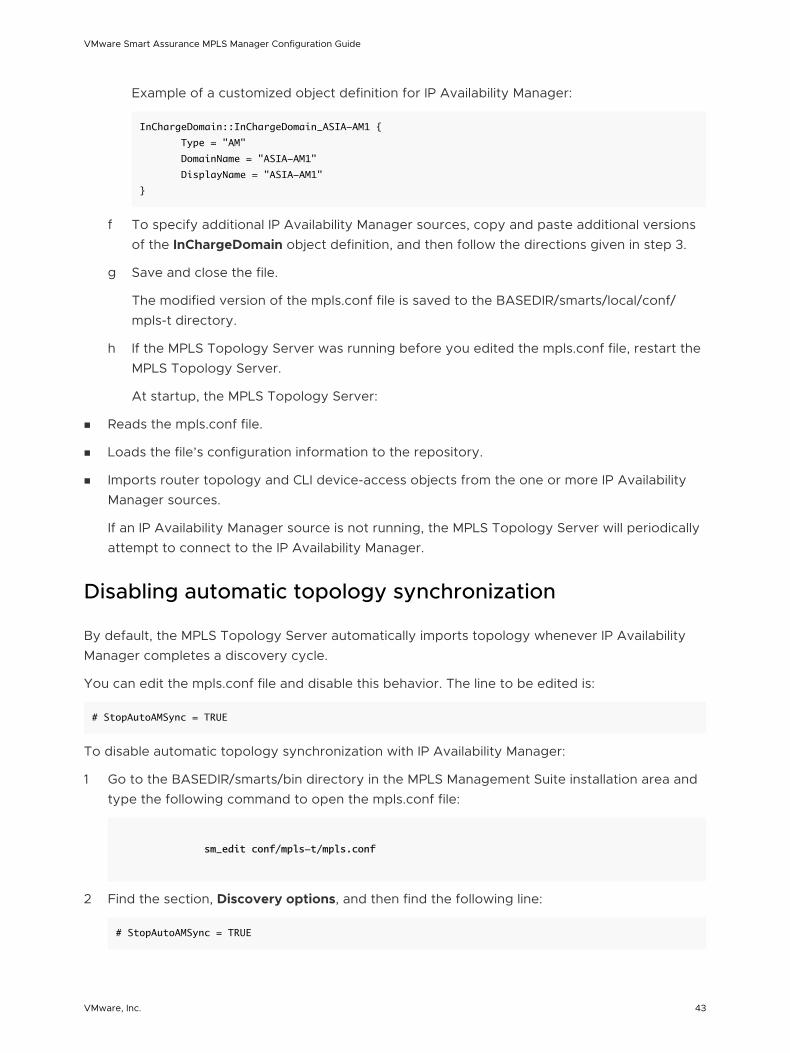
Example of a customized object definition for IP Availability Manager:
InChargeDomain::InChargeDomain_ASIA-AM1 {
Type = "AM"
DomainName = "ASIA-AM1"
DisplayName = "ASIA-AM1"
}
f To specify additional IP Availability Manager sources, copy and paste additional versions of the InChargeDomain object definition, and then follow the directions given in step 3.
g Save and close the file.
The modified version of the mpls.conf file is saved to the BASEDIR/smarts/local/conf/mpls-t directory.
h If the MPLS Topology Server was running before you edited the mpls.conf file, restart the MPLS Topology Server.
At startup, the MPLS Topology Server:
n Reads the mpls.conf file.
n Loads the file’s configuration information to the repository.
n Imports router topology and CLI device-access objects from the one or more IP Availability Manager sources.
If an IP Availability Manager source is not running, the MPLS Topology Server will periodically attempt to connect to the IP Availability Manager.
Disabling automatic topology synchronization
By default, the MPLS Topology Server automatically imports topology whenever IP Availability Manager completes a discovery cycle.
You can edit the mpls.conf file and disable this behavior. The line to be edited is:
# StopAutoAMSync = TRUE
To disable automatic topology synchronization with IP Availability Manager:
1 Go to the BASEDIR/smarts/bin directory in the MPLS Management Suite installation area and type the following command to open the mpls.conf file:
sm_edit conf/mpls-t/mpls.conf
2 Find the section, Discovery options, and then find the following line:
# StopAutoAMSync = TRUE
VMware Smart Assurance MPLS Manager Configuration Guide
VMware, Inc. 43
3 Uncomment the line by removing the # character.
4 Save and close the file.
The modified version of the mpls.conf file is saved to the BASEDIR/smarts/local/conf/mpls-t directory.
5 If the MPLS Topology Server was running before you edited the mpls.conf file, restart the MPLS Topology Server.
Prohibiting CLI discovery for certain devices
By default, CLI discovery is available for all devices.
You can edit the mpls.conf file and prohibit CLI discovery for certain devices. The block of lines to be edited is:
# CLIProhibitType = "CLI_SYSTEMNAME"
# CLIProhibitPattern = "*"
Because CLIProhibitPattern is an empty string by default, CLI discovery is available for all devices by default.
To prohibit CLI discovery for certain devices:
1 Go to the BASEDIR/smarts/bin directory in the MPLS Management Suite installation area and type the following command to open the mpls.conf file:
sm_edit conf/mpls-t/mpls.conf
2 Find the section, CLI options, and then uncomment the following lines (shown uncommented):
CLIProhibitType = "CLI_SYSTEMNAME"
CLIProhibitPattern = "*"
3 For the CLIProhibitPattern parameter, replace the asterisk with the device IP addresses or names that should not be discovered. Use the wildcard characters described in Chapter 11 Wildcard Patterns to specify ranges of IP addresses or ranges of names; for example, 172.16.* or R1*.
For 172.16.*, all devices that have loopback IP addresses beginning with the string 172.16 will become members of the group. For R1*, all devices that have names beginning with the string R1 will become members of the group. The devices that become members of the group will be excluded from CLI discovery, and the devices that do not become members of the group will be included in CLI discovery.
VMware Smart Assurance MPLS Manager Configuration Guide
VMware, Inc. 44
4 Depending on whether IP addresses or names are specified in the previous step, set the CLIProhibitType parameter to the appropriate option, as indicated below:
n IP address: Use CLI_AGENTADDRESS
n Name: Use CLI_SYSTEMNAME
5 Save and close the file.
The modified version of the mpls.conf file is saved to the BASEDIR/smarts/local/conf/mpls-t directory.
6 If the MPLS Topology Server was running before you edited the mpls.conf file, restart the MPLS Topology Server.
Enabling MPLS-BGP cross-domain correlation
By default, the MPLS-BGP cross-domain correlation feature is disabled.
You can edit the mpls.conf file and enable this feature. The lines to be edited are:
# ENABLE_XD_EBGP=TRUE
# ENABLE_XD_IBGP=TRUE
.
.
.
InChargeDomain::InChargeDomain_INCHARGE-BGP {
Type = "BGP"
DomainName = "INCHARGE-BGP"
DisplayName = "INCHARGE-BGP"
}
To enable MPLS-BGP cross-domain correlation:
1 Go to the BASEDIR/smarts/bin directory in the MPLS Management Suite installation area and type the following command to open the mpls.conf file:
sm_edit conf/mpls-t/mpls.conf
2 Find the section, L2vpn options, and then find the following lines:
# ENABLE_XD_EBGP=TRUE
# ENABLE_XD_IBGP=TRUE
3 Uncomment either of the lines or both lines by removing the # character.
An uncommented ENABLE_XD_EBGP=TRUE enables the MPLS Topology Server to discover eBGP sessions.
An uncommented ENABLE_XD_IBGP=TRUE enables the MPLS Topology Server to discover iBGP sessions.
VMware Smart Assurance MPLS Manager Configuration Guide
VMware, Inc. 45
4 Find the section, Instances of BGP Server, and then find the following object definition:
InChargeDomain::InChargeDomain_INCHARGE-BGP {
Type = "BGP"
DomainName = "INCHARGE-BGP"
DisplayName = "INCHARGE-BGP"
}
5 Make the following edits to the object definition:
6 On the InChargeDomain and DomainName lines, change INCHARGE-BGP to the name of your Network Protocol Manager for BGP.
7 On the DisplayName line, change INCHARGE-BGP to the name that you want to see for the Network Protocol Manager for BGP in the Global Console.
Example of a customized object definition for Network Protocol Manager for BGP:
InChargeDomain::InChargeDomain_ASIA-BGP1 {
Type = "BGP"
DomainName = "ASIA-BGP1"
DisplayName = "ASIA-BGP1"
}
8 Save and close the file.
The modified version of the mpls.conf file is saved to the BASEDIR/smarts/local/conf/mpls-t directory.
9 If the MPLS Topology Server was running before you edited the mpls.conf file, restart the MPLS Topology Server.
Disabling MulticastGroup Impacted events
By default, the MulticastGroup Impacted event for the multicast VPN feature is enabled. However, there may be occasions when impacted events that are related to the multicast VPN traffic should not be forwarded to the Global Manager.
You can edit the notfication.conf file and disable the impacted event. The line to be edited is:
# Enable_MulticastGroup_Impacted = FALSE
To disable the MulticastGroup Impacted event:
1 Go to the BASEDIR/smarts/bin directory in the MPLS Management Suite installation area and type the following command to open the notification.conf file:
sm_edit conf/mpls-a/notification.conf
VMware Smart Assurance MPLS Manager Configuration Guide
VMware, Inc. 46
2 Find the following line:
# Enable_MulticastGroup_Impacted = FALSE
3 Uncomment the line by removing the # character.
4 Save and close the file.
The modified version of the notification.conf file is saved to the BASEDIR/smarts/local/conf/mpls-a/notification.conf directory.
5 If the MPLS Analysis Server was running before you edited the notification.conf file, restart the MPLS Analysis Server
Enabling remote ping functionality
The variable, SM_ENABLE_SNMP_SET, must be set to TRUE in order for remote ping to work. Starting with MPLS Management Suite 4.0, this variable is set to TRUE by default in the runcmd_env.sh file.
For releases prior to MPLS Management Suite 4.0, the remote ping functionality is disabled for the MPLS Topology Server and the MPLS Monitoring Server.
If you copied the runcmd_env.sh file from an older release to use with MPLS Management Suite 4.0 or higher, check to determine whether this variable is set properly. If not, enable the remote ping functionality by adding the following environment variable definition to the runcmd_env.sh file:
SM_ENABLE_SNMP_SET=TRUE
The runcmd_env.sh file in the MPLS Management Suite installation area will automatically set the SM_ENABLE_SNMP_SET environment variable, along with any other environment variables in the file, for each application or utility that is started from the installation area.
To enable the remote ping functionality:
1 Go to the BASEDIR/smarts/bin directory in the MPLS Management Suite installation area and type the following command to open the runcmd_env.sh file:
sm_edit conf/runcmd_env.sh
2 Add the following line to the file:
SM_ENABLE_SNMP_SET=TRUE
3 Save and close the file.
VMware Smart Assurance MPLS Manager Configuration Guide
VMware, Inc. 47
The modified version of the runcmd_env.sh file is saved to the BASEDIR/smarts/local/conf directory.
4 If the MPLS Topology Server and the MPLS Monitoring Server were running before you edited the runcmd_env.sh file, restart each server.
The VMware Smart Assurance MPLS Management Suite User Guide provides information about invoking an on-demand remote ping and deploying a periodic remote ping instance. Chapter 9 Configuring Polling and Remote Ping Groups provides the procedure for deploying periodic remote ping instances.
Changing remote ping global values
Each newly invoked on-demand remote ping or newly deployed periodic remote ping instance inherits the global values that are specified in the REMOTEPING.conf file. The global parameters and their values are described in #unique_49/unique_49_Connect_42__MPLS_CONFIG_MPLS_97913.
The WriteCommunity value that is defined in the REMOTEPING.conf file is included in a remote ping request only if MPLS Manager cannot find a match for the target device in a System Write Community Strings group. System Write Community Strings remote ping group provides information about modifying or creating a System Write Community Strings group. Chapter 13 Configuring a Community String for Juniper Ping MIB Access provides information about configuring a community string for Juniper Ping MIB access.
As explained in #unique_49/unique_49_Connect_42__MPLS_CONFIG_MPLS_71308, there are two REMOTEPING.conf files:
n One in the mpls-t directory—intended for the MPLS Topology Server
n One in the mpls-m directory—intended for the MPLS Monitoring Server
The REMOTEPING.conf file in the mpls-t directory contains eight parameters, one of which is NumberOfThreads. The REMOTEPING.conf file in the mpls-m directory contains just the NumberOfThreads parameter. You can modify the parameters in both files.
When running, the remote ping manager in the MPLS Monitoring Server will obtain all of its attribute values except NumberOfThreads from the remote ping manager in the MPLS Topology Server. It will obtain its NumberOfThreads value from the REMOTEPING.conf file in the mpls-m directory.
To change the remote ping global values for the MPLS Topology Server:
a Go to the BASEDIR/smarts/bin directory in the MPLS Management Suite installation area and type the following command to open the REMOTEPING.conf file:
sm_edit conf/mpls-t/REMOTEPING.conf
VMware Smart Assurance MPLS Manager Configuration Guide
VMware, Inc. 48
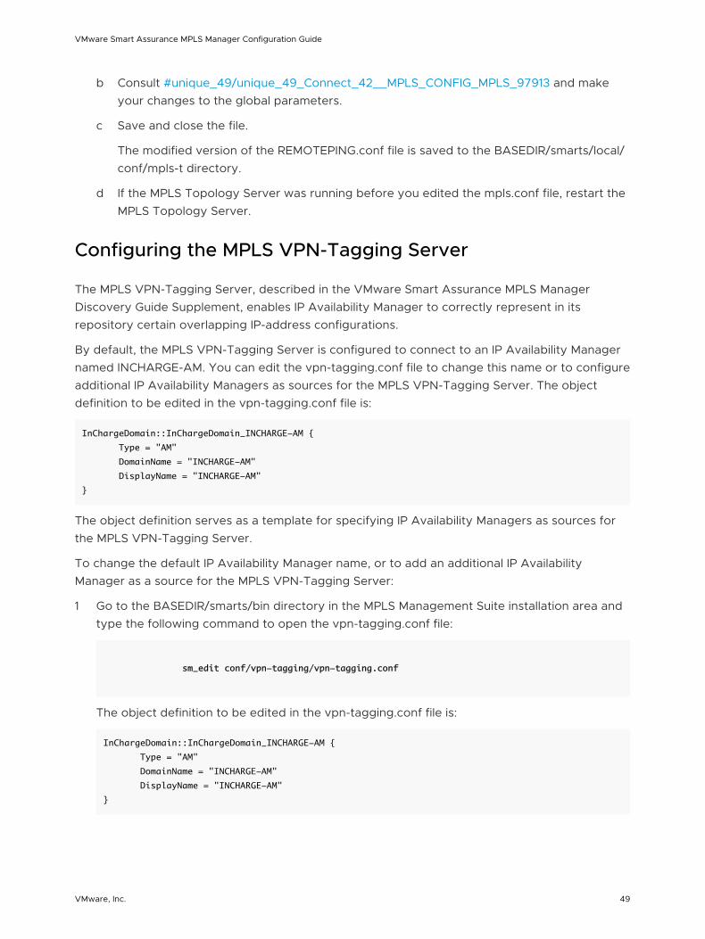
b Consult #unique_49/unique_49_Connect_42__MPLS_CONFIG_MPLS_97913 and make your changes to the global parameters.
c Save and close the file.
The modified version of the REMOTEPING.conf file is saved to the BASEDIR/smarts/local/conf/mpls-t directory.
d If the MPLS Topology Server was running before you edited the mpls.conf file, restart the MPLS Topology Server.
Configuring the MPLS VPN-Tagging Server
The MPLS VPN-Tagging Server, described in the VMware Smart Assurance MPLS Manager Discovery Guide Supplement, enables IP Availability Manager to correctly represent in its repository certain overlapping IP-address configurations.
By default, the MPLS VPN-Tagging Server is configured to connect to an IP Availability Manager named INCHARGE-AM. You can edit the vpn-tagging.conf file to change this name or to configure additional IP Availability Managers as sources for the MPLS VPN-Tagging Server. The object definition to be edited in the vpn-tagging.conf file is:
InChargeDomain::InChargeDomain_INCHARGE-AM {
Type = "AM"
DomainName = "INCHARGE-AM"
DisplayName = "INCHARGE-AM"
}
The object definition serves as a template for specifying IP Availability Managers as sources for the MPLS VPN-Tagging Server.
To change the default IP Availability Manager name, or to add an additional IP Availability Manager as a source for the MPLS VPN-Tagging Server:
1 Go to the BASEDIR/smarts/bin directory in the MPLS Management Suite installation area and type the following command to open the vpn-tagging.conf file:
sm_edit conf/vpn-tagging/vpn-tagging.conf
The object definition to be edited in the vpn-tagging.conf file is:
InChargeDomain::InChargeDomain_INCHARGE-AM {
Type = "AM"
DomainName = "INCHARGE-AM"
DisplayName = "INCHARGE-AM"
}
VMware Smart Assurance MPLS Manager Configuration Guide
VMware, Inc. 49
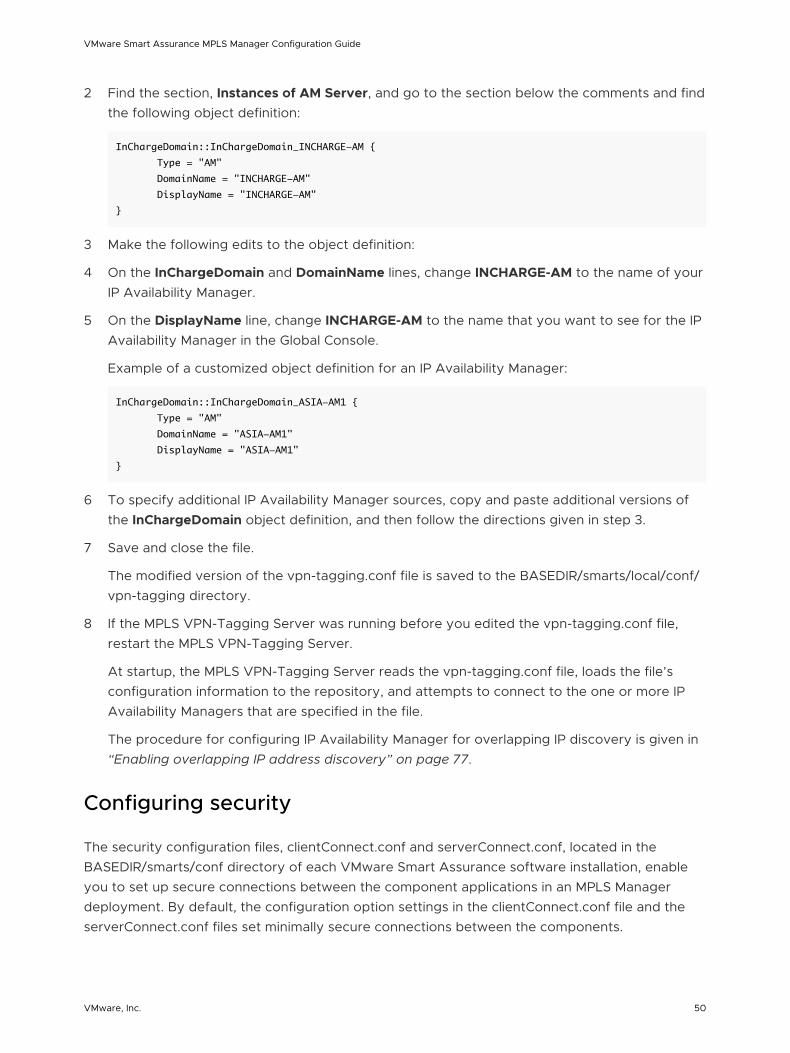
2 Find the section, Instances of AM Server, and go to the section below the comments and find the following object definition:
InChargeDomain::InChargeDomain_INCHARGE-AM {
Type = "AM"
DomainName = "INCHARGE-AM"
DisplayName = "INCHARGE-AM"
}
3 Make the following edits to the object definition:
4 On the InChargeDomain and DomainName lines, change INCHARGE-AM to the name of your IP Availability Manager.
5 On the DisplayName line, change INCHARGE-AM to the name that you want to see for the IP Availability Manager in the Global Console.
Example of a customized object definition for an IP Availability Manager:
InChargeDomain::InChargeDomain_ASIA-AM1 {
Type = "AM"
DomainName = "ASIA-AM1"
DisplayName = "ASIA-AM1"
}
6 To specify additional IP Availability Manager sources, copy and paste additional versions of the InChargeDomain object definition, and then follow the directions given in step 3.
7 Save and close the file.
The modified version of the vpn-tagging.conf file is saved to the BASEDIR/smarts/local/conf/vpn-tagging directory.
8 If the MPLS VPN-Tagging Server was running before you edited the vpn-tagging.conf file, restart the MPLS VPN-Tagging Server.
At startup, the MPLS VPN-Tagging Server reads the vpn-tagging.conf file, loads the file’s configuration information to the repository, and attempts to connect to the one or more IP Availability Managers that are specified in the file.
The procedure for configuring IP Availability Manager for overlapping IP discovery is given in “Enabling overlapping IP address discovery” on page 77.
Configuring security
The security configuration files, clientConnect.conf and serverConnect.conf, located in the BASEDIR/smarts/conf directory of each VMware Smart Assurance software installation, enable you to set up secure connections between the component applications in an MPLS Manager deployment. By default, the configuration option settings in the clientConnect.conf file and the serverConnect.conf files set minimally secure connections between the components.
VMware Smart Assurance MPLS Manager Configuration Guide
VMware, Inc. 50

The VMware Smart Assurance System Administration Guide presents detailed information about VMware Smart Assurance secure communications.
VMware Smart Assurance MPLS Manager Configuration Guide
VMware, Inc. 51
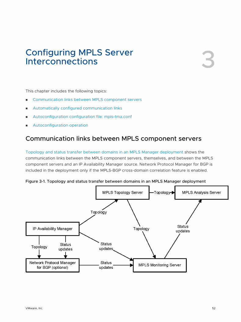
Configuring MPLS Server Interconnections 3This chapter includes the following topics:
n Communication links between MPLS component servers
n Automatically configured communication links
n Autoconfiguration configuration file: mpls-tma.conf
n Autoconfiguration operation
Communication links between MPLS component servers
Topology and status transfer between domains in an MPLS Manager deployment shows the communication links between the MPLS component servers, themselves, and between the MPLS component servers and an IP Availability Manager source. Network Protocol Manager for BGP is included in the deployment only if the MPLS-BGP cross-domain correlation feature is enabled.
Figure 3-1. Topology and status transfer between domains in an MPLS Manager deployment
VMware, Inc. 52
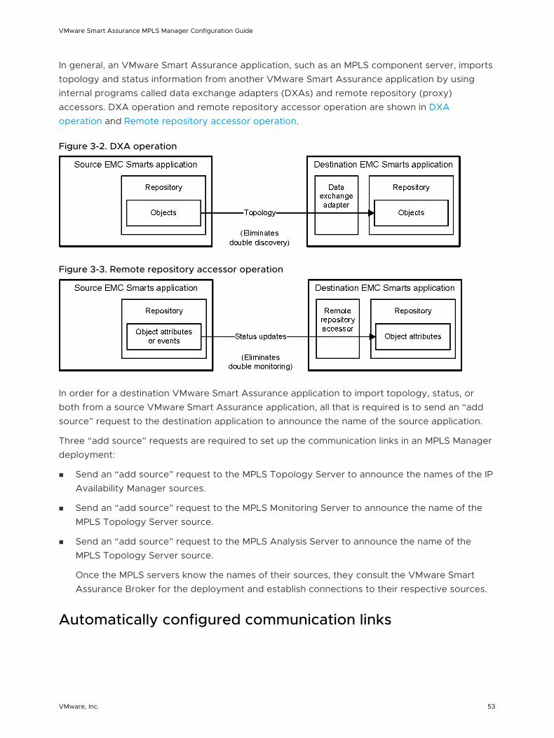
In general, an VMware Smart Assurance application, such as an MPLS component server, imports topology and status information from another VMware Smart Assurance application by using internal programs called data exchange adapters (DXAs) and remote repository (proxy) accessors. DXA operation and remote repository accessor operation are shown in DXA operation and Remote repository accessor operation.
Figure 3-2. DXA operation
Figure 3-3. Remote repository accessor operation
In order for a destination VMware Smart Assurance application to import topology, status, or both from a source VMware Smart Assurance application, all that is required is to send an “add source” request to the destination application to announce the name of the source application.
Three “add source” requests are required to set up the communication links in an MPLS Manager deployment:
n Send an “add source” request to the MPLS Topology Server to announce the names of the IP Availability Manager sources.
n Send an “add source” request to the MPLS Monitoring Server to announce the name of the MPLS Topology Server source.
n Send an “add source” request to the MPLS Analysis Server to announce the name of the MPLS Topology Server source.
Once the MPLS servers know the names of their sources, they consult the VMware Smart Assurance Broker for the deployment and establish connections to their respective sources.
Automatically configured communication links
VMware Smart Assurance MPLS Manager Configuration Guide
VMware, Inc. 53
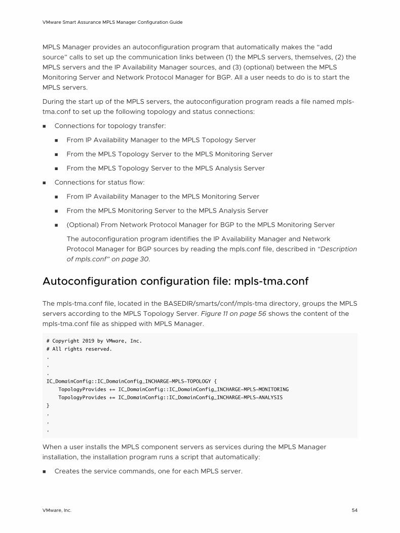
MPLS Manager provides an autoconfiguration program that automatically makes the “add source” calls to set up the communication links between (1) the MPLS servers, themselves, (2) the MPLS servers and the IP Availability Manager sources, and (3) (optional) between the MPLS Monitoring Server and Network Protocol Manager for BGP. All a user needs to do is to start the MPLS servers.
During the start up of the MPLS servers, the autoconfiguration program reads a file named mpls-tma.conf to set up the following topology and status connections:
n Connections for topology transfer:
n From IP Availability Manager to the MPLS Topology Server
n From the MPLS Topology Server to the MPLS Monitoring Server
n From the MPLS Topology Server to the MPLS Analysis Server
n Connections for status flow:
n From IP Availability Manager to the MPLS Monitoring Server
n From the MPLS Monitoring Server to the MPLS Analysis Server
n (Optional) From Network Protocol Manager for BGP to the MPLS Monitoring Server
The autoconfiguration program identifies the IP Availability Manager and Network Protocol Manager for BGP sources by reading the mpls.conf file, described in “Description of mpls.conf” on page 30.
Autoconfiguration configuration file: mpls-tma.conf
The mpls-tma.conf file, located in the BASEDIR/smarts/conf/mpls-tma directory, groups the MPLS servers according to the MPLS Topology Server. Figure 11 on page 56 shows the content of the mpls-tma.conf file as shipped with MPLS Manager.
# Copyright 2019 by VMware, Inc.
# All rights reserved.
.
.
.
IC_DomainConfig::IC_DomainConfig_INCHARGE-MPLS-TOPOLOGY {
TopologyProvides += IC_DomainConfig::IC_DomainConfig_INCHARGE-MPLS-MONITORING
TopologyProvides += IC_DomainConfig::IC_DomainConfig_INCHARGE-MPLS-ANALYSIS
}
.
.
.
When a user installs the MPLS component servers as services during the MPLS Manager installation, the installation program runs a script that automatically:
n Creates the service commands, one for each MPLS server.
VMware Smart Assurance MPLS Manager Configuration Guide
VMware, Inc. 54
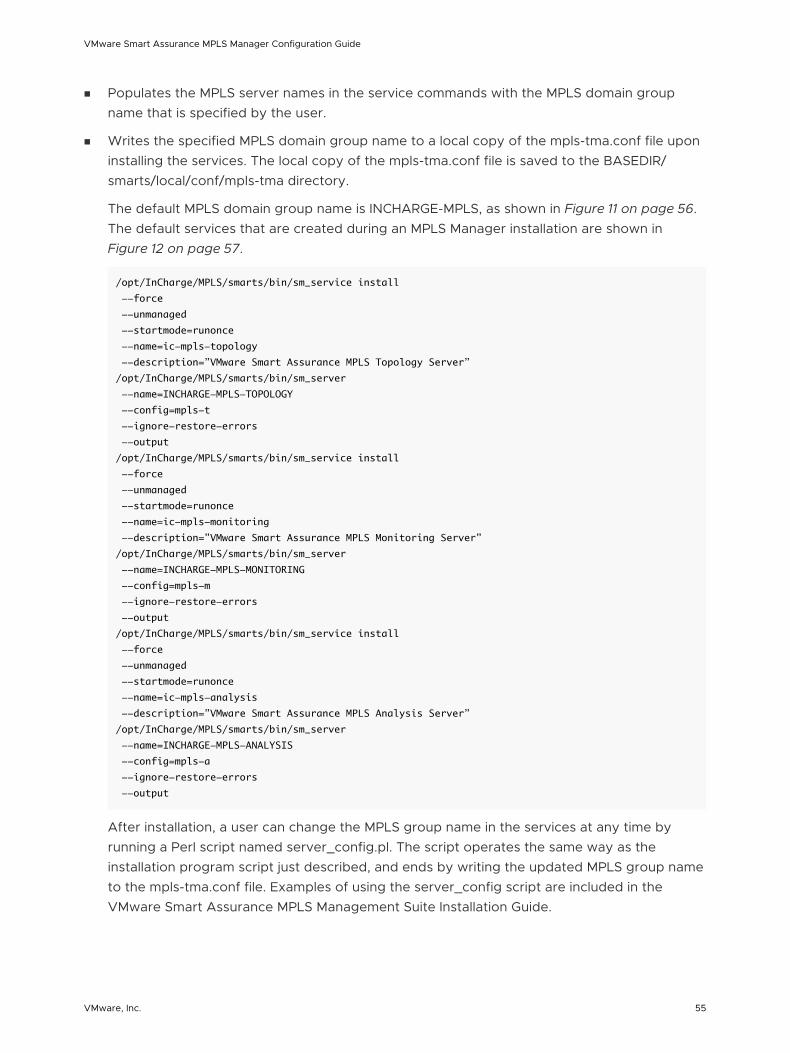
n Populates the MPLS server names in the service commands with the MPLS domain group name that is specified by the user.
n Writes the specified MPLS domain group name to a local copy of the mpls-tma.conf file upon installing the services. The local copy of the mpls-tma.conf file is saved to the BASEDIR/smarts/local/conf/mpls-tma directory.
The default MPLS domain group name is INCHARGE-MPLS, as shown in Figure 11 on page 56. The default services that are created during an MPLS Manager installation are shown in Figure 12 on page 57.
/opt/InCharge/MPLS/smarts/bin/sm_service install
--force
--unmanaged
--startmode=runonce
--name=ic-mpls-topology
--description=”VMware Smart Assurance MPLS Topology Server”
/opt/InCharge/MPLS/smarts/bin/sm_server
--name=INCHARGE-MPLS-TOPOLOGY
--config=mpls-t
--ignore-restore-errors
--output
/opt/InCharge/MPLS/smarts/bin/sm_service install
--force
--unmanaged
--startmode=runonce
--name=ic-mpls-monitoring
--description=”VMware Smart Assurance MPLS Monitoring Server”
/opt/InCharge/MPLS/smarts/bin/sm_server
--name=INCHARGE-MPLS-MONITORING
--config=mpls-m
--ignore-restore-errors
--output
/opt/InCharge/MPLS/smarts/bin/sm_service install
--force
--unmanaged
--startmode=runonce
--name=ic-mpls-analysis
--description=”VMware Smart Assurance MPLS Analysis Server”
/opt/InCharge/MPLS/smarts/bin/sm_server
--name=INCHARGE-MPLS-ANALYSIS
--config=mpls-a
--ignore-restore-errors
--output
After installation, a user can change the MPLS group name in the services at any time by running a Perl script named server_config.pl. The script operates the same way as the installation program script just described, and ends by writing the updated MPLS group name to the mpls-tma.conf file. Examples of using the server_config script are included in the VMware Smart Assurance MPLS Management Suite Installation Guide.
VMware Smart Assurance MPLS Manager Configuration Guide
VMware, Inc. 55
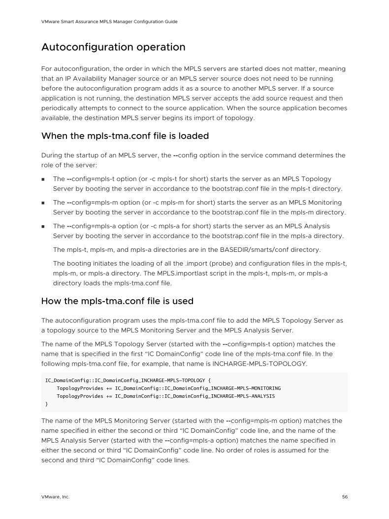
Autoconfiguration operation
For autoconfiguration, the order in which the MPLS servers are started does not matter, meaning that an IP Availability Manager source or an MPLS server source does not need to be running before the autoconfiguration program adds it as a source to another MPLS server. If a source application is not running, the destination MPLS server accepts the add source request and then periodically attempts to connect to the source application. When the source application becomes available, the destination MPLS server begins its import of topology.
When the mpls-tma.conf file is loaded
During the startup of an MPLS server, the --config option in the service command determines the role of the server:
n The --config=mpls-t option (or -c mpls-t for short) starts the server as an MPLS Topology Server by booting the server in accordance to the bootstrap.conf file in the mpls-t directory.
n The --config=mpls-m option (or -c mpls-m for short) starts the server as an MPLS Monitoring Server by booting the server in accordance to the bootstrap.conf file in the mpls-m directory.
n The --config=mpls-a option (or -c mpls-a for short) starts the server as an MPLS Analysis Server by booting the server in accordance to the bootstrap.conf file in the mpls-a directory.
The mpls-t, mpls-m, and mpls-a directories are in the BASEDIR/smarts/conf directory.
The booting initiates the loading of all the .import (probe) and configuration files in the mpls-t, mpls-m, or mpls-a directory. The MPLS.importlast script in the mpls-t, mpls-m, or mpls-a directory loads the mpls-tma.conf file.
How the mpls-tma.conf file is used
The autoconfiguration program uses the mpls-tma.conf file to add the MPLS Topology Server as a topology source to the MPLS Monitoring Server and the MPLS Analysis Server.
The name of the MPLS Topology Server (started with the --config=mpls-t option) matches the name that is specified in the first “IC DomainConfig” code line of the mpls-tma.conf file. In the following mpls-tma.conf file, for example, that name is INCHARGE-MPLS-TOPOLOGY.
IC_DomainConfig::IC_DomainConfig_INCHARGE-MPLS-TOPOLOGY {
TopologyProvides += IC_DomainConfig::IC_DomainConfig_INCHARGE-MPLS-MONITORING
TopologyProvides += IC_DomainConfig::IC_DomainConfig_INCHARGE-MPLS-ANALYSIS
}
The name of the MPLS Monitoring Server (started with the --config=mpls-m option) matches the name specified in either the second or third “IC DomainConfig” code line, and the name of the MPLS Analysis Server (started with the --config=mpls-a option) matches the name specified in either the second or third “IC DomainConfig” code line. No order of roles is assumed for the second and third “IC DomainConfig” code lines.
VMware Smart Assurance MPLS Manager Configuration Guide
VMware, Inc. 56
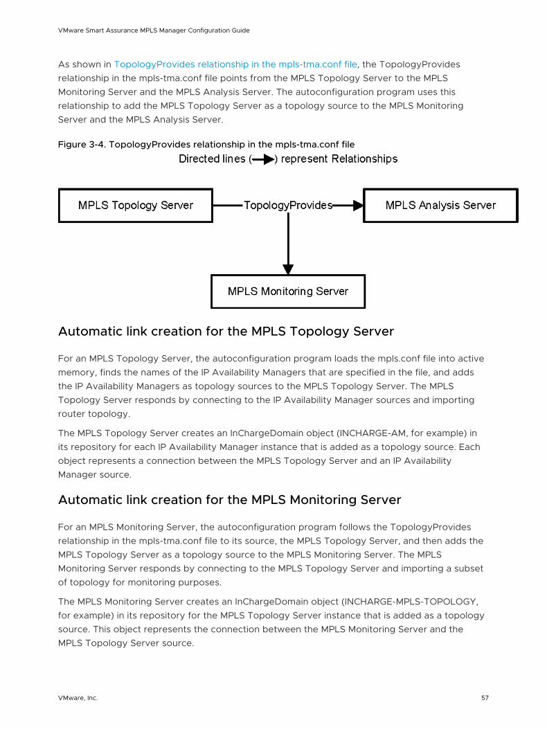
As shown in TopologyProvides relationship in the mpls-tma.conf file, the TopologyProvides relationship in the mpls-tma.conf file points from the MPLS Topology Server to the MPLS Monitoring Server and the MPLS Analysis Server. The autoconfiguration program uses this relationship to add the MPLS Topology Server as a topology source to the MPLS Monitoring Server and the MPLS Analysis Server.
Figure 3-4. TopologyProvides relationship in the mpls-tma.conf file
Automatic link creation for the MPLS Topology Server
For an MPLS Topology Server, the autoconfiguration program loads the mpls.conf file into active memory, finds the names of the IP Availability Managers that are specified in the file, and adds the IP Availability Managers as topology sources to the MPLS Topology Server. The MPLS Topology Server responds by connecting to the IP Availability Manager sources and importing router topology.
The MPLS Topology Server creates an InChargeDomain object (INCHARGE-AM, for example) in its repository for each IP Availability Manager instance that is added as a topology source. Each object represents a connection between the MPLS Topology Server and an IP Availability Manager source.
Automatic link creation for the MPLS Monitoring Server
For an MPLS Monitoring Server, the autoconfiguration program follows the TopologyProvides relationship in the mpls-tma.conf file to its source, the MPLS Topology Server, and then adds the MPLS Topology Server as a topology source to the MPLS Monitoring Server. The MPLS Monitoring Server responds by connecting to the MPLS Topology Server and importing a subset of topology for monitoring purposes.
The MPLS Monitoring Server creates an InChargeDomain object (INCHARGE-MPLS-TOPOLOGY, for example) in its repository for the MPLS Topology Server instance that is added as a topology source. This object represents the connection between the MPLS Monitoring Server and the MPLS Topology Server source.
VMware Smart Assurance MPLS Manager Configuration Guide
VMware, Inc. 57
After the MPLS Monitoring Server establishes a connection to the MPLS Topology Server and imports a subset of the topology, which includes the InChargeDomain objects that represent the IP Availability Managers, the MPLS Monitoring Server is able to determine its proxy sources by reading the names of the imported InChargeDomain objects. It then adds the IP Availability Managers as proxy sources, connects to them, and subscribes to MPLS-relevant statuses.
When MPLS-BGP cross-domain correlation is enabled, the MPLS Monitoring Server also fetches the name of the Network Protocol Manager for BGP from the MPLS Topology Server. It then adds the Network Protocol Manager for BGP as a proxy source, connects to it, and subscribes to BGP-relevant statuses.
Lastly, when the MPLS Monitoring Server establishes a connection to the MPLS Topology Server, the MPLS Topology Server creates an InChargeDomain object (INCHARGE-MPLS-MONITORING, for example) in its repository for the connected MPLS Monitoring Server. Among other things, this object serves as a reference for the MPLS Analysis Server.
Automatic link creation for the MPLS Analysis Server
For an MPLS Analysis Server, the autoconfiguration program follows the TopologyProvides relationship in the mpls-tma.conf file to its source, the MPLS Topology Server, and then adds the MPLS Topology Server as a topology source to the MPLS Analysis Server. The MPLS Analysis Server responds by connecting to the MPLS Topology Server and importing a subset of topology for analysis purposes.
The MPLS Analysis Server creates an InChargeDomain object (INCHARGE-MPLS-TOPOLOGY, for example) in its repository for the MPLS Topology Server instance that is added as a topology source. This object represents the connection between the MPLS Analysis Server and the MPLS Topology Server source.
After the MPLS Analysis Server establishes a connection to the MPLS Topology Server and imports a subset of the topology, which includes the InChargeDomain object that represents the MPLS Monitoring Server, it is able to determine its proxy source by reading the name of the imported InChargeDomain object. It then adds the MPLS Monitoring Server as a proxy source, connects to it, and subscribes to MPLS- and VPN-relevant statuses, and to BGP-relevant statuses when MPLS-BGP cross-domain correlation is enabled.
VMware Smart Assurance MPLS Manager Configuration Guide
VMware, Inc. 58
Opening the Global Console 4This chapter includes the following topics:
n Global Console overview
n User accounts and passwords
n Procedure for opening the Global Console
n Procedure for opening the Global Manager Administration Console
n Procedure for opening the Domain Manager Administration Console
n Procedure for opening the Polling and Thresholds Console
Global Console overview
The Global Console is a collection of many consoles, or console views, that together enable administrators to manage VMware Smart Assurance Domain Managers and Global Managers.
You will use the following three consoles to complete the configuration and administration tasks required to set up a MPLS Manager deployment:
n Domain Manager Administration Console
Enables administrators to manage Domain Managers; for example, to view and respond to discovery results and errors.
n Global Manager Administration Console
Enables administrators to configure the Global Manager; for example, to set up connections to underlying Domain Managers, to enable map types that are disabled by default, or to enable server tools that are disabled by default.
n Polling and Thresholds Console
Enables administrators to control periodic polling, to set thresholds for polled data, and to deploy and customize special groups such as CLI device-access groups and periodic remote ping groups.
User accounts and passwords
VMware, Inc. 59
Attaching the Global Console to a Domain Manager (such as MPLS Manager) or to a Global Manager requires an VMware Smart Assurance user account. The default user accounts are as follows:
n Administration account:
n username: admin
n password: changeme
n Operator account:
n username: oper
n password: oper
For users logged on with an administration account, the Global Console includes a Configure menu. This menu enables administrators to open the Domain Manager Administration Console and the Global Manager Administration Console.
The VMware Smart Assurance System Administration Guide provides information about changing the password for the default administrative account (recommended) and configuring access privileges. The VMware Smart Assurance Service Assurance Manager Configuration Guide provides information about configuring permissions to perform specific console operations.
Procedure for opening the Global Console
To open the Global Console:
1 Start the Global Console.
n n On a UNIX system, go to the BASEDIR/smarts/bin directory in the Service Assurance Manager( Global Manager) installation area and type:
sm_gui
Press Enter.
The Attach Managerdialog box opens as shown in Attach Manager dialog box.
VMware Smart Assurance MPLS Manager Configuration Guide
VMware, Inc. 60
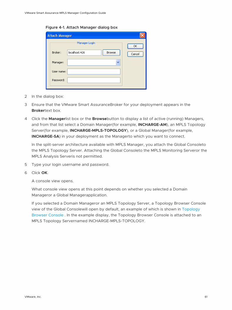
Figure 4-1. Attach Manager dialog box
2 In the dialog box:
3 Ensure that the VMware Smart AssuranceBroker for your deployment appears in the Brokertext box.
4 Click the Managerlist box or the Browsebutton to display a list of active (running) Managers, and from that list select a Domain Manager(for example, INCHARGE-AM), an MPLS Topology Server(for example, INCHARGE-MPLS-TOPOLOGY), or a Global Manager(for example, INCHARGE-SA) in your deployment as the Managerto which you want to connect.
In the split-server architecture available with MPLS Manager, you attach the Global Consoleto the MPLS Topology Server. Attaching the Global Consoleto the MPLS Monitoring Serveror the MPLS Analysis Serveris not permitted.
5 Type your login username and password.
6 Click OK.
A console view opens.
What console view opens at this point depends on whether you selected a Domain Manageror a Global Managerapplication.
If you selected a Domain Manageror an MPLS Topology Server, a Topology Browser Console view of the Global Consolewill open by default, an example of which is shown in Topology Browser Console . In the example display, the Topology Browser Console is attached to an MPLS Topology Servernamed INCHARGE-MPLS-TOPOLOGY.
VMware Smart Assurance MPLS Manager Configuration Guide
VMware, Inc. 61
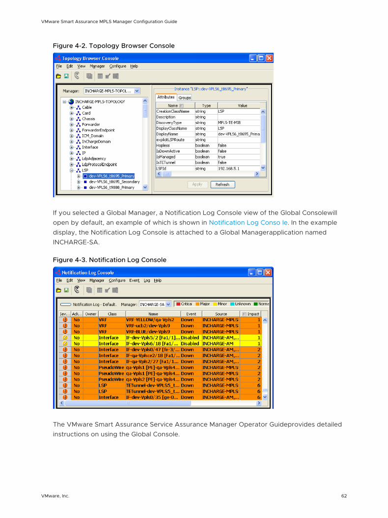
Figure 4-2. Topology Browser Console
If you selected a Global Manager, a Notification Log Console view of the Global Consolewill open by default, an example of which is shown in Notification Log Conso le. In the example display, the Notification Log Console is attached to a Global Managerapplication named INCHARGE-SA.
Figure 4-3. Notification Log Console
The VMware Smart Assurance Service Assurance Manager Operator Guideprovides detailed instructions on using the Global Console.
VMware Smart Assurance MPLS Manager Configuration Guide
VMware, Inc. 62
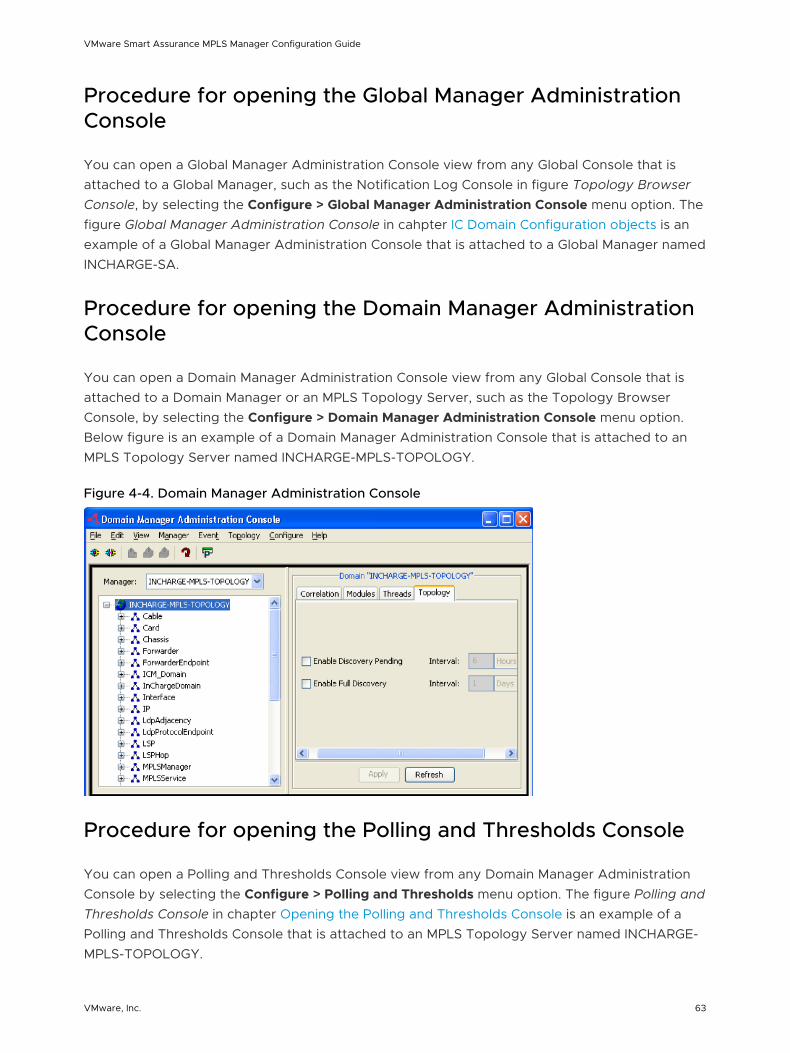
Procedure for opening the Global Manager Administration Console
You can open a Global Manager Administration Console view from any Global Console that is attached to a Global Manager, such as the Notification Log Console in figure Topology Browser Console, by selecting the Configure > Global Manager Administration Console menu option. The figure Global Manager Administration Console in cahpter IC Domain Configuration objects is an example of a Global Manager Administration Console that is attached to a Global Manager named INCHARGE-SA.
Procedure for opening the Domain Manager Administration Console
You can open a Domain Manager Administration Console view from any Global Console that is attached to a Domain Manager or an MPLS Topology Server, such as the Topology Browser Console, by selecting the Configure > Domain Manager Administration Console menu option. Below figure is an example of a Domain Manager Administration Console that is attached to an MPLS Topology Server named INCHARGE-MPLS-TOPOLOGY.
Figure 4-4. Domain Manager Administration Console
Procedure for opening the Polling and Thresholds Console
You can open a Polling and Thresholds Console view from any Domain Manager Administration Console by selecting the Configure > Polling and Thresholds menu option. The figure Polling and Thresholds Console in chapter Opening the Polling and Thresholds Console is an example of a Polling and Thresholds Console that is attached to an MPLS Topology Server named INCHARGE-MPLS-TOPOLOGY.
VMware Smart Assurance MPLS Manager Configuration Guide
VMware, Inc. 63
Configuring IP Availability Manager 5This chapter includes the following topics:
n Configuration overview
n Topology and CLI device-access object import
n About the MPLS topology collection sets
n Tagged IP object import
n CLI discovery, LSP ping, and CLI device-access objects
n Enabling and customizing MPLS light discovery
n Enabling overlapping IP address discovery
n Enabling interoperability with the MPLS VPN-Tagging Server
n Creating CLI device-access groups
n Enabling BGP light discovery
Configuration overview
For an IP Availability Manager in an MPLS Manager deployment, an administrator performs the standard configuration tasks that are presented in the VMware Smart Assurance IP Manager User Guide to prepare the IP Availability Manager application for SNMP discovery.
The administrator also performs the following additional configuration tasks to prepare IP Availability Manager for operation in an MPLS Manager deployment:
n Enables MPLS light discovery (mandatory in most cases).
n Enables BGP light discovery for MPLS-BGP cross-domain correlation (optional).
n Enables overlapping IP address discovery (optional).
n Enables interoperability with the MPLS VPN-Tagging Server (optional).
n Creates CLI device-access objects for MPLS Manager (mandatory).
VMware, Inc. 64
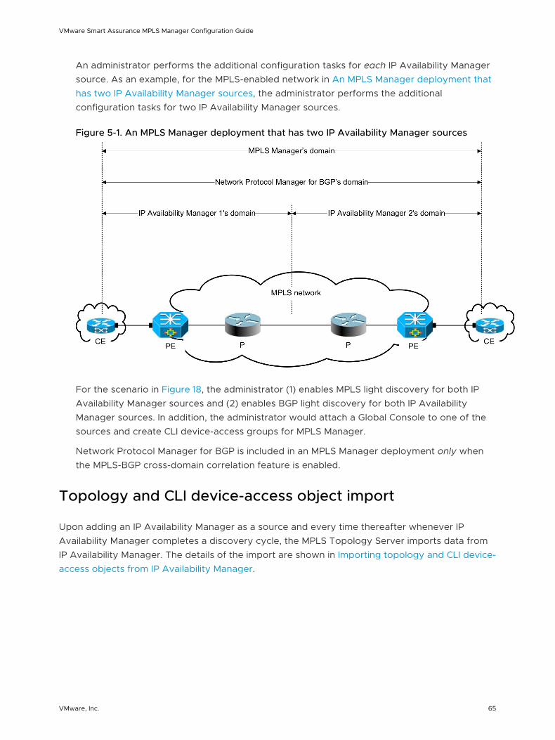
An administrator performs the additional configuration tasks for each IP Availability Manager source. As an example, for the MPLS-enabled network in An MPLS Manager deployment that has two IP Availability Manager sources, the administrator performs the additional configuration tasks for two IP Availability Manager sources.
Figure 5-1. An MPLS Manager deployment that has two IP Availability Manager sources
For the scenario in Figure 18, the administrator (1) enables MPLS light discovery for both IP Availability Manager sources and (2) enables BGP light discovery for both IP Availability Manager sources. In addition, the administrator would attach a Global Console to one of the sources and create CLI device-access groups for MPLS Manager.
Network Protocol Manager for BGP is included in an MPLS Manager deployment only when the MPLS-BGP cross-domain correlation feature is enabled.
Topology and CLI device-access object import
Upon adding an IP Availability Manager as a source and every time thereafter whenever IP Availability Manager completes a discovery cycle, the MPLS Topology Server imports data from IP Availability Manager. The details of the import are shown in Importing topology and CLI device-access objects from IP Availability Manager.
VMware Smart Assurance MPLS Manager Configuration Guide
VMware, Inc. 65
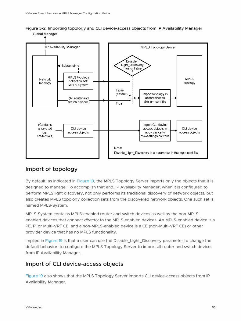
Figure 5-2. Importing topology and CLI device-access objects from IP Availability Manager
Import of topology
By default, as indicated in Figure 19, the MPLS Topology Server imports only the objects that it is designed to manage. To accomplish that end, IP Availability Manager, when it is configured to perform MPLS light discovery, not only performs its traditional discovery of network objects, but also creates MPLS topology collection sets from the discovered network objects. One such set is named MPLS-System.
MPLS-System contains MPLS-enabled router and switch devices as well as the non-MPLS-enabled devices that connect directly to the MPLS-enabled devices. An MPLS-enabled device is a PE, P, or Multi-VRF CE, and a non-MPLS-enabled device is a CE (non-Multi-VRF CE) or other provider device that has no MPLS functionality.
Implied in Figure 19 is that a user can use the Disable_Light_Discovery parameter to change the default behavior, to configure the MPLS Topology Server to import all router and switch devices from IP Availability Manager.
Import of CLI device-access objects
Figure 19 also shows that the MPLS Topology Server imports CLI device-access objects from IP Availability Manager.
VMware Smart Assurance MPLS Manager Configuration Guide
VMware, Inc. 66
IP Availability Manager maintains these user-created CLI device-access objects, which are required by MPLS Manager to perform CLI discovery or to execute LSP ping requests. Instructions for creating CLI device-access objects are given in “Creating CLI device-access groups” on page 79.
Types of imported objects
Topology and CLI device-access objects imported from IP Availability Manager identifies the types of objects that are imported by the MPLS Topology Server from IP Availability Manager. The MPLS Topology Server imports the topology and CLI device-access objects in accordance to the dxa-am.conf and dxa-settings.conf files in the BASEDIR/smarts/conf/mpls-t directory.
VMware Smart Assurance MPLS Manager Configuration Guide
VMware, Inc. 67
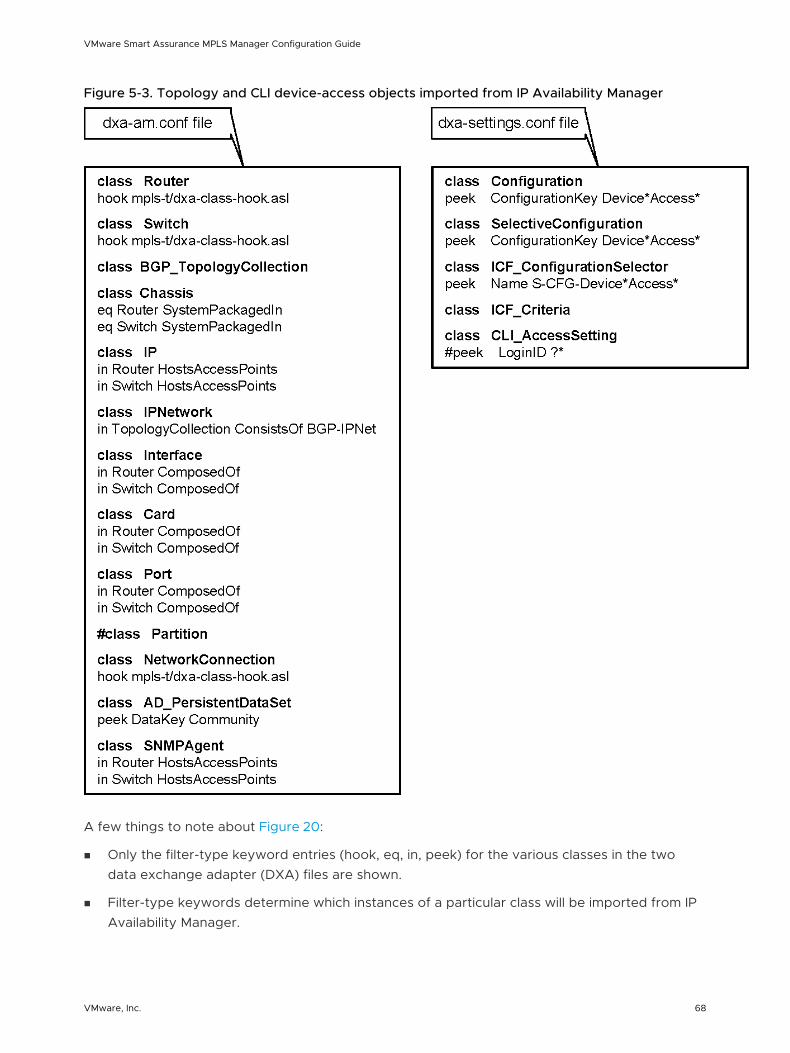
Figure 5-3. Topology and CLI device-access objects imported from IP Availability Manager
A few things to note about Figure 20:
n Only the filter-type keyword entries (hook, eq, in, peek) for the various classes in the two data exchange adapter (DXA) files are shown.
n Filter-type keywords determine which instances of a particular class will be imported from IP Availability Manager.
VMware Smart Assurance MPLS Manager Configuration Guide
VMware, Inc. 68
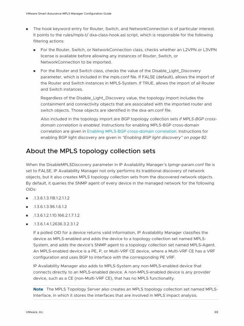
n The hook keyword entry for Router, Switch, and NetworkConnection is of particular interest. It points to the rules/mpls-t/ dxa-class-hook.asl script, which is responsible for the following filtering actions:
n For the Router, Switch, or NetworkConnection class, checks whether an L2VPN or L3VPN license is available before allowing any instances of Router, Switch, or NetworkConnection to be imported.
n For the Router and Switch class, checks the value of the Disable_Light_Discovery parameter, which is included in the mpls.conf file. If FALSE (default), allows the import of the Router and Switch instances in MPLS-System. If TRUE, allows the import of all Router and Switch instances.
Regardless of the Disable_Light_Discovery value, the topology import includes the containment and connectivity objects that are associated with the imported router and switch objects. Those objects are identified in the dxa-am.conf file.
Also included in the topology import are BGP topology collection sets if MPLS-BGP cross-domain correlation is enabled. Instructions for enabling MPLS-BGP cross-domain correlation are given in Enabling MPLS-BGP cross-domain correlation. Instructions for enabling BGP light discovery are given in “Enabling BGP light discovery” on page 82.
About the MPLS topology collection sets
When the DisableMPLSDiscovery parameter in IP Availability Manager’s tpmgr-param.conf file is set to FALSE, IP Availability Manager not only performs its traditional discovery of network objects, but it also creates MPLS topology collection sets from the discovered network objects. By default, it queries the SNMP agent of every device in the managed network for the following OIDs:
n .1.3.6.1.3.118.1.2.1.1.2
n .1.3.6.1.3.96.1.6.1.2
n .1.3.6.1.2.1.10.166.2.1.7.1.2
n .1.3.6.1.4.1.2636.3.2.3.1.2
If a polled OID for a device returns valid information, IP Availability Manager classifies the device as MPLS-enabled and adds the device to a topology collection set named MPLS-System, and adds the device’s SNMP agent to a topology collection set named MPLS-Agent. An MPLS-enabled device is a PE, P, or Multi-VRF CE device, where a Multi-VRF CE has a VRF configuration and uses BGP to interface with the corresponding PE VRF.
IP Availability Manager also adds to MPLS-System any non-MPLS-enabled device that connects directly to an MPLS-enabled device. A non-MPLS-enabled device is any provider device, such as a CE (non-Multi-VRF CE), that has no MPLS functionality.
Note The MPLS Topology Server also creates an MPLS topology collection set named MPLS-Interface, in which it stores the interfaces that are involved in MPLS impact analysis.
VMware Smart Assurance MPLS Manager Configuration Guide
VMware, Inc. 69
The MPLS light discovery feature is described in the VMware Smart Assurance IP Manager Concepts Guide and the VMware Smart Assurance IP Manager User Guide. Instructions for enabling the MPLS light discovery feature are given in “Enabling and customizing MPLS light discovery” on page 76.
Tagged IP object import
Included in the topology import from IP Availability Manager are IP objects, which may be tagged or untagged. Tagged IP objects enable a Domain Manager to include overlapping IP addresses in its modeled topology.
The inclusion of overlapping IP addresses in the modeled topology results in a more accurate and more complete model of the topology, which enables IP Availability Manager and MPLS Manager to perform more accurate correlation analysis.
Overlapping IP addresses
In a networked environment, the same IP addresses can be reused and configured across multiple systems (devices) that are running in separate networks. These IP addresses, known as overlapping IP addresses, are prominent in (1) MPLS VPN environments and (2) networks that are centrally managed by Managed Service Providers, where private IP networks of customers often deploy identically numbered IP address spaces.
IP tagging feature
The IP tagging feature enables IP Availability Managerto discover and create IP objects for both VRF and non-VRF overlapping IP addresses, where a non-VRF overlapping IP address is defined as an overlapping IP address that is not part of an MPLS VPN.
The MPLS Topology Serveris able to understand VRF IP objects that have been tagged by IP Availability Manager.
For an IP object that is created for a discovered VRF IP address, IP Availability Managertags the object with the route distinguisher (RD) value of the VRF to which the VRF IP address belongs. IP Availability Manageralso creates a corresponding IPNetwork object and tags it with the same value that is used to tag the IP object. And, for both tagged IP and IPNetwork objects, IP Availability Managersets the object’s Tag attribute to the tag value that is used to tag the object.
The IP tagging feature is described in the VMware Smart Assurance IP Manager Concepts Guideand the VMware Smart Assurance IP Manager User Guide. Instructions for enabling the IP tagging feature are given in “Enabling overlapping IP address discovery” on page 77.
MPLS VPN-Tagging Server
VMware Smart Assurance MPLS Manager Configuration Guide
VMware, Inc. 70
The MPLS VPN-Tagging Server enables IP Availability Manager to correctly represent in its modeled topology certain VRF overlapping IP-address configurations. When the MPLS VPN-Tagging Server discovers these configurations, it sends the connection information to IP Availability Manager so that IP Availability Manager can distinguish the overlapping IP addresses in the configurations. Doing so enables IP Availability Manager to create the correct network connections for the configurations.
Creating the correct network connections means that the MPLS Topology Server will import more accurate topology information from IP Availability Manager.
Instructions for configuring IP Availability Manager to interoperate with the MPLS VPN-Tagging Server are given in “Enabling interoperability with the MPLS VPN-Tagging Server” on page 78.
CLI discovery, LSP ping, and CLI device-access objects
The MPLS Topology Server performs CLI discovery and executes on-demand LSP ping requests. As shown in CLI discovery, LSP ping, and CLI device-access object creation and transfer, CLI discovery and LSP ping are controlled by CLI device-access objects that are created on the IP Availability Manager, through the Polling and Thresholds Console, and then imported by the MPLS Topology Server.
VMware Smart Assurance MPLS Manager Configuration Guide
VMware, Inc. 71
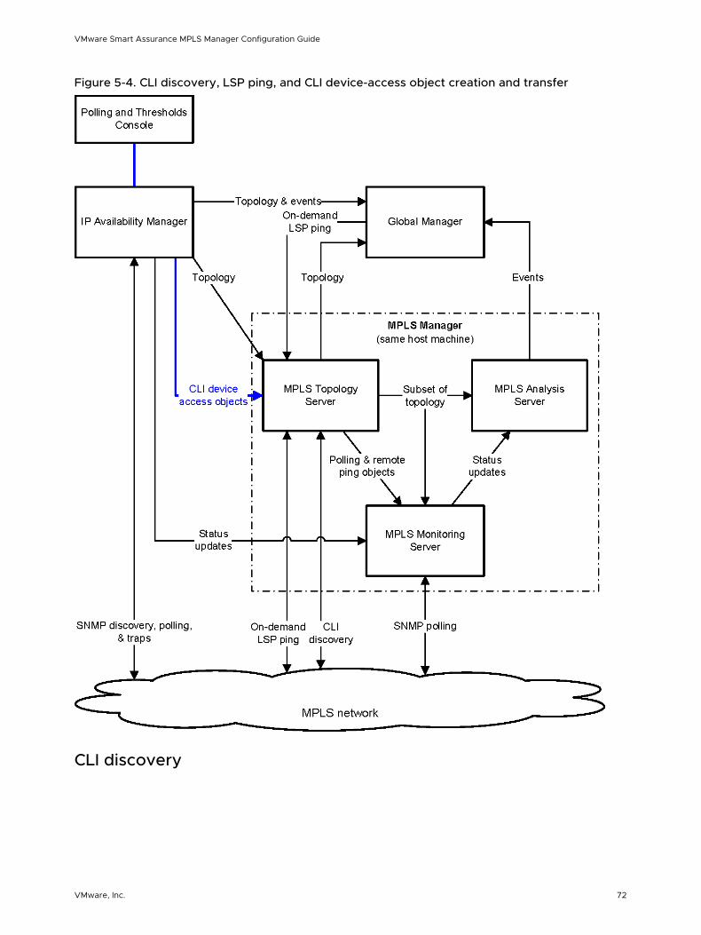
Figure 5-4. CLI discovery, LSP ping, and CLI device-access object creation and transfer
CLI discovery
VMware Smart Assurance MPLS Manager Configuration Guide
VMware, Inc. 72
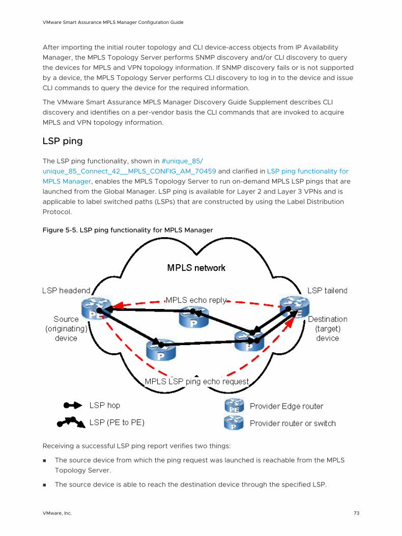
After importing the initial router topology and CLI device-access objects from IP Availability Manager, the MPLS Topology Server performs SNMP discovery and/or CLI discovery to query the devices for MPLS and VPN topology information. If SNMP discovery fails or is not supported by a device, the MPLS Topology Server performs CLI discovery to log in to the device and issue CLI commands to query the device for the required information.
The VMware Smart Assurance MPLS Manager Discovery Guide Supplement describes CLI discovery and identifies on a per-vendor basis the CLI commands that are invoked to acquire MPLS and VPN topology information.
LSP ping
The LSP ping functionality, shown in #unique_85/unique_85_Connect_42__MPLS_CONFIG_AM_70459 and clarified in LSP ping functionality for MPLS Manager, enables the MPLS Topology Server to run on-demand MPLS LSP pings that are launched from the Global Manager. LSP ping is available for Layer 2 and Layer 3 VPNs and is applicable to label switched paths (LSPs) that are constructed by using the Label Distribution Protocol.
Figure 5-5. LSP ping functionality for MPLS Manager
Receiving a successful LSP ping report verifies two things:
n The source device from which the ping request was launched is reachable from the MPLS Topology Server.
n The source device is able to reach the destination device through the specified LSP.
VMware Smart Assurance MPLS Manager Configuration Guide
VMware, Inc. 73
The LSP ping functionality is built on the CLI tool framework that is described in Chapter 10 Building CLI-Based Server Tools on the CLI Framework
Chapter 6 Configuring the Global Manager describes how to enable the use of on-demand LSP ping server tools. The VMware Smart Assurance MPLS Management Suite User Guide describes LSP ping operation.
CLI device-access objects
The execution of CLI discovery or LSP ping requires login credentials, which are used by the MPLS Topology Server to access MPLS-enabled devices and to invoke CLI commands from the devices. The CLI device-access objects carry the login credential information.
Instructions for creating CLI device access objects for the MPLS Topology Server are given in “Creating CLI device-access groups” on page 79.
Enabling and customizing MPLS light discovery
You, as an administrator, use the following parameters in the tpmgr-param.conf file of each IP Availability Manager source to enable and customize MPLS light discovery:
n DisableMPLSDiscovery
n PollableMPLSOids
Enable MPLS light discovery
By default, IP Availability Manager is not enabled to perform MPLS light discovery. To enable this feature, set the DisableMPLSDiscovery parameter in IP Availability Manager’s tpmgr-param.conf file to FALSE.
To enable MPLS light discovery:
1 Go to the BASEDIR/smarts/bin directory in the IP Manager installation area and type the following command to open the tpmgr-param.conf file:
sm_edit conf/discovery/tpmgr-param.conf
2 Set the following parameter to FALSE:
DisableMPLSDiscovery FALSE
3 Save and close the file.
The modified version of the tpmgr-param.conf file is saved to the BASEDIR/smarts/local/conf/discovery directory.
VMware Smart Assurance MPLS Manager Configuration Guide
VMware, Inc. 74
4 If IP Availability Manager was running before you edited the tpmgr-param.conf file, type the following command from BASEDIR/smarts/bin to make your change take effect:
sm_tpmgr -s <IP Availability Manager instance name> --load-conf=tpmgr-
param.conf
Specify MPLS device-matching filters
By default, the PollableMPLSOids parameter in IP Availability Manager’s tpmgr-param.conf file specifies a list of pipe (|) separated OIDs, which are to be polled by IP Availability Manager to create the MPLS topology collection set.
Recommended OIDs for MPLS light discovery identifies the OIDs that are recommended for MPLS light discovery. The actual list of OIDs that you specify for PollableMPLSOids depends on your environment.
Table 5-1. Recommended OIDs for MPLS light discovery
OID Name MIB
.1.3.6.1.3.118.1.2.1.1.2 mplsVpnInterfaceLabelEdgeType MPLS-VPN-MIB
.1.3.6.1.3.96.1.6.1.2 mplsOutSegmentIfIndex MPLS-LSR-MIB
.1.3.6.1.2.1.10.166.2.1.7.1.2 InterfaceIndexOrZero MPLS-LSR-STD-MIB
.1.3.6.1.4.1.2636.3.2.3.1.2 mplsLspState MPLS-MIB
When MPLS light discovery is enabled, IP Availability Manager will include in the MPLS topology collection set any discovered device that matches any of the OIDs in the PollableMPLSOids parameter.
Consult the VMware Smart Assurance IP Manager User Guide and follow the instructions to specify MPLS device-matching filters.
Enabling overlapping IP address discovery
By default, IP Availability Manager is not enabled to perform overlapping IP address discovery. To enable this feature, set the following parameters in IP Availability Manager’s tpmgr-param.conf file to the shown values:
DisableOverlappingIP FALSE
UseVPNIP FALSE
EnableShadowIP TRUE (default)
Be aware that in IP Manager 7.0.4, the UseVPNIP value is TRUE by default because of the following uncommented entry in the tpmgr-param.conf file:
UseVPNIP TRUE
VMware Smart Assurance MPLS Manager Configuration Guide
VMware, Inc. 75
Because this entry has been deleted from the tpmgr-param.conf file in IP Manager 8.1, add UseVPNIP FALSE to the tpmgr-param.conf file to ensure that tagged IP and IPNetwork objects, not VPNIP and VPNIPNetwork objects, are created for the discovered VRF IP addresses.
To enable overlapping IP discovery:
1 Go to the BASEDIR/smarts/bin directory in the IP Manager installation area and type the following command to open the tpmgr-param.conf file:
sm_edit conf/discovery/tpmgr-param.conf
2 Set the following three parameters to the values shown:
DisableOverlappingIP FALSE
UseVPNIP FALSE
EnableShadowIP TRUE
3 Save and close the file.
The modified version of the tpmgr-param.conf file is saved to the BASEDIR/smarts/local/conf/discovery directory.
4 If IP Availability Manager was running before you edited the tpmgr-param.conf file, type the following command from BASEDIR/smarts/bin to make your change take effect:
sm_tpmgr -s <IP Availability Manager instance name> --load-conf=tpmgr-
param.conf
Enabling interoperability with the MPLS VPN-Tagging Server
To enhance overlapping IP address discovery, you enable IP Availability Manager to interoperate with the MPLS VPN-Tagging Server.
Assuming that the DisableOverlappingIP, UseVPNIP, and EnableShadowIP parameters in the tpmgr-param.conf file are set as specified in the previous section, you do so by setting the following parameter in IP Availability Manager’s discovery.conf file to TRUE:
importExternalTagsConnections TRUE
In addition, you need to enable the MPLS VPN-Tagging Server to interoperate with IP Availability Manager. You do so by adding IP Availability Manager as a source to the MPLS VPN-Tagging Server.
VMware Smart Assurance MPLS Manager Configuration Guide
VMware, Inc. 76
To enable interoperability between IP Availability Manager and the MPLS VPN-Tagging Server:
1 Consult the VMware Smart Assurance IP Manager Reference Guide and the VMware Smart Assurance IP Manager User Guide and follow the instructions to set the following parameter in the discovery.conf file to the value shown:
importExternalTagsConnections TRUE
2 Consult “Configuring the MPLS VPN-Tagging Server” on page 51 and follow the instructions to add IP Availability Manager as a source to the MPLS VPN-Tagging Server.
The MPLS VPN-Tagging Server performs overlapping-IP and corresponding network-connection discovery in two vendor-specific environments: Cisco and Alcatel-Lucent. To complete the configuration of the MPLS VPN-Tagging Server, open the BASEDIR/smarts/conf/vpn-tagging/vpn-tagging.conf file and perform the following additional tasks:
n Mandatory and for Alcatel-Lucent only: Add the Enable5620SAMDiscovery parameter with a value of TRUE to the vpn-tagging.conf file.
n Optional and for Alcatel-Lucent only: Modify the default values of the AlcatelDiscoveryInterval parameter.
n Optional and for Cisco only: Modify the default values of the DiscoveryFilter parameter.
These parameters are described in “Description of vpn-tagging.conf” on page 43.
Descriptions of MPLS VPN-Tagging Server discovery are given in the VMware Smart Assurance MPLS Manager Discovery Guide Supplement.
Creating CLI device-access groups
Because IP Availability Manager is a component of many VMware Smart Assurance deployments, IP Availability Manager has been selected as the central repository for specifying and storing device-access credentials, such as the login credentials that are required by the MPLS Topology Server to perform CLI discovery or to execute LSP ping requests.
When the MPLS Topology Server adds IP Availability Manager as a source, as explained in the VMware Smart Assurance MPLS Manager Discovery Guide Supplement, the MPLS Topology Server imports the device-access credentials from IP Availability Manager and makes the credentials available to the CLI discovery driver and the LSP ping driver.
You use the Polling and Thresholds Console to specify sets of device-access credentials in the form of CLI device-access groups. Each CLI device-access group contains:
n An access-protocol method: Telnet, SSH1, or SSH2; Telnet, by default.
n A set of device-access credentials: a username, a user password, and a privileged-mode enable password.
n A set of member devices for which the access method and device-access credentials apply.
VMware Smart Assurance MPLS Manager Configuration Guide
VMware, Inc. 77
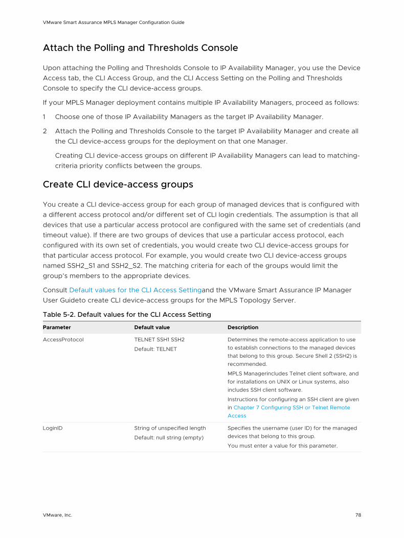
Attach the Polling and Thresholds Console
Upon attaching the Polling and Thresholds Console to IP Availability Manager, you use the Device Access tab, the CLI Access Group, and the CLI Access Setting on the Polling and Thresholds Console to specify the CLI device-access groups.
If your MPLS Manager deployment contains multiple IP Availability Managers, proceed as follows:
1 Choose one of those IP Availability Managers as the target IP Availability Manager.
2 Attach the Polling and Thresholds Console to the target IP Availability Manager and create all the CLI device-access groups for the deployment on that one Manager.
Creating CLI device-access groups on different IP Availability Managers can lead to matching-criteria priority conflicts between the groups.
Create CLI device-access groups
You create a CLI device-access group for each group of managed devices that is configured with a different access protocol and/or different set of CLI login credentials. The assumption is that all devices that use a particular access protocol are configured with the same set of credentials (and timeout value). If there are two groups of devices that use a particular access protocol, each configured with its own set of credentials, you would create two CLI device-access groups for that particular access protocol. For example, you would create two CLI device-access groups named SSH2_S1 and SSH2_S2. The matching criteria for each of the groups would limit the group’s members to the appropriate devices.
Consult Default values for the CLI Access Settingand the VMware Smart Assurance IP Manager User Guideto create CLI device-access groups for the MPLS Topology Server.
Table 5-2. Default values for the CLI Access Setting
Parameter Default value Description
AccessProtocol TELNET SSH1 SSH2
Default: TELNET
Determines the remote-access application to use to establish connections to the managed devices that belong to this group. Secure Shell 2 (SSH2) is recommended.
MPLS Managerincludes Telnet client software, and for installations on UNIX or Linux systems, also includes SSH client software.
Instructions for configuring an SSH client are given in Chapter 7 Configuring SSH or Telnet Remote Access
LoginID String of unspecified length
Default: null string (empty)
Specifies the username (user ID) for the managed devices that belong to this group.
You must enter a value for this parameter.
VMware Smart Assurance MPLS Manager Configuration Guide
VMware, Inc. 78
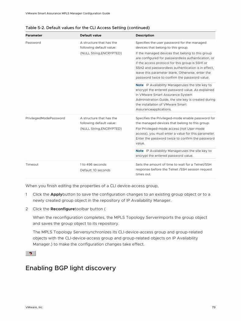
Table 5-2. Default values for the CLI Access Setting (continued)
Parameter Default value Description
Password A structure that has the following default value:
{NULL String,ENCRYPTED}
Specifies the user password for the managed devices that belong to this group.
If the managed devices that belong to this group are configured for passwordless authentication, or if the access protocol for this group is SSH1 or SSH2 and passwordless authentication is in effect, leave this parameter blank. Otherwise, enter the password twice to confirm the password value.
Note IP Availability Manageruses the site key to encrypt the entered password value. As explained in VMware Smart Assurance System Administration Guide, the site key is created during the installation of VMware Smart Assuranceapplications.
PrivilegedModePassword A structure that has the following default value:
{NULL String,ENCRYPTED}
Specifies the Privileged-mode enable password for the managed devices that belong to this group.
For Privileged-mode access (not User-mode access), you must enter a value for this parameter. Enter the password twice to confirm the password value.
Note IP Availability Manageruses the site key to encrypt the entered password value.
Timeout 1 to 496 seconds
Default: 10 seconds
Sets the amount of time to wait for a Telnet/SSH response before the Telnet /SSH session request times out.
When you finish editing the properties of a CLI device-access group,
1 Click the Applybutton to save the configuration changes to an existing group object or to a newly created group object in the repository of IP Availability Manager.
2 Click the Reconfiguretoolbar button (
When the reconfiguration completes, the MPLS Topology Serverimports the group object and saves the group object to its repository.
The MPLS Topology Serversynchronizes its CLI-device-access group and group-related objects with the CLI-device-access group and group-related objects on IP Availability Manager.) to make the configuration changes take effect.
Enabling BGP light discovery
VMware Smart Assurance MPLS Manager Configuration Guide
VMware, Inc. 79
By default, IP Availability Manager is not enabled to perform BGP light discovery. To enable this feature, set the DisableProtocolDiscovery parameter in IP Availability Manager’s tpmgr-param.conf file to FALSE.
To enable BGP light discovery:
1 Go to the BASEDIR/smarts/bin directory in the IP Manager installation area and type the following command to open the tpmgr-param.conf file:
sm_edit conf/discovery/tpmgr-param.conf
2 Set the following parameter to FALSE:
DisableProtocolDiscovery FALSE
3 Save and close the file.
The modified version of the tpmgr-param.conf file is saved to the BASEDIR/smarts/local/conf/discovery directory.
4 If IP Availability Manager was running before you edited the tpmgr-param.conf file, type the following command from BASEDIR/smarts/bin to make your change take effect:
sm_tpmgr -s <IP Availability Manager instance name> --load-conf=tpmgr-
param.conf
VMware Smart Assurance MPLS Manager Configuration Guide
VMware, Inc. 80
Configuring the Global Manager 6This chapter includes the following topics:
n Configuration overview
n About the Global Manager
n IC Domain Configuration objects
n Specifying the underlying domains
n Enabling the display of MPLS maps
n Enabling the use of MPLS remote ping and LSP ping server tools
n Enabling the subscription of remote ping down and impaired events
n Changing LSP ping global values
Configuration overview
For the Global Manager to import topology and events from the underlying components in an MPLS Manager deployment, you, as an administrator, must configure the Global Manager with the proper data exchange adapter (DXA) files. The Global Manager integrates and correlates the imported topology and events, and relates the data to services and customers.
You use the Global Console and the Global Manager to configure the DXA files. The VMware Smart Assurance Service Assurance Manager Configuration Guide provides detailed instructions on using the Global Console to complete Global Manager configurations.
If the MPLS-BGP cross-domain correlation feature is enabled in your deployment, refer to the VMware Smart Assurance Network Protocol Manager Configuration Guide for instructions on associating the underlying Network Protocol Manager for BGP with the proper DXA file in the Global Manager.
If the managed MPLS environment contains Next Generation Multicast VPNs (NG MVPNs) and draft-Rosen MVPNs, you should include an VMware Smart Assurance Multicast Manager in your deployment so that you can view the draft-Rosen MVPNs. MPLS Manager will discover the Juniper-based NG MVPNs and the multicast groups of the NG MVPNs, and Multicast Manager will
VMware, Inc. 81
discover the draft-Rosen MVPNs and the multicast groups of the draft-Rosen MVPNs. In addition, Multicast Manager will discover the multicast groups of the NG MVPNs. Refer to the VMware Smart Assurance Multicast Manager User Guide for instructions on associating the underlying Multicast Manager with the proper DXA file in the Global Manager.
About the Global Manager
Most of the configuration tasks for configuring the Global Manager in an MPLS Manager deployment are accomplished by using the Global Manager Administration Console view of the Global Console. Global Manager Administration Console interaction with the Global Manager summarizes the Global Manager Administration Console interaction with the Global Manager.
VMware Smart Assurance MPLS Manager Configuration Guide
VMware, Inc. 82
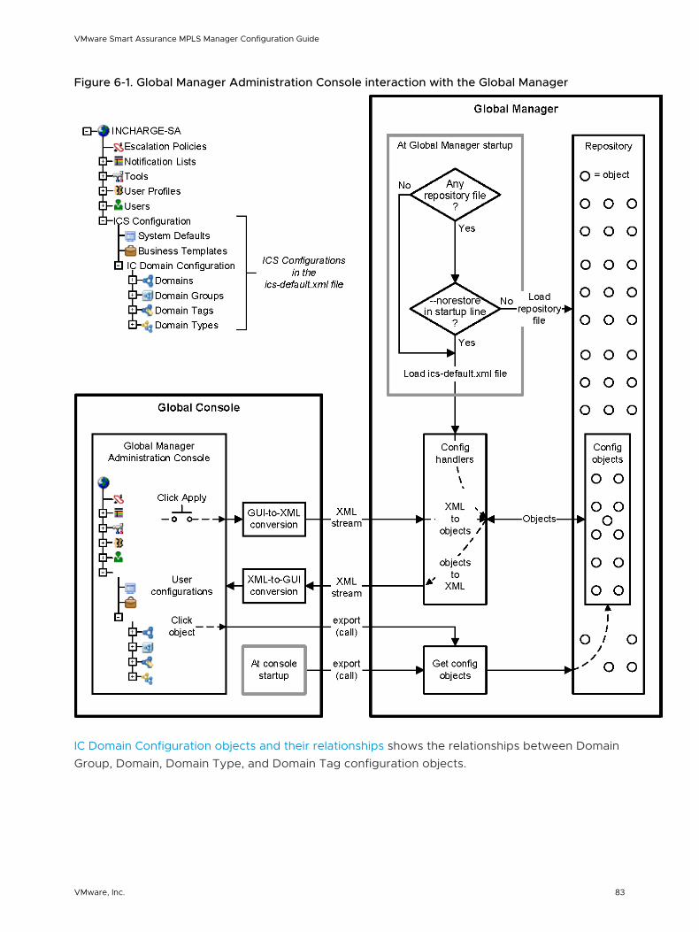
Figure 6-1. Global Manager Administration Console interaction with the Global Manager
IC Domain Configuration objects and their relationships shows the relationships between Domain Group, Domain, Domain Type, and Domain Tag configuration objects.
VMware Smart Assurance MPLS Manager Configuration Guide
VMware, Inc. 83
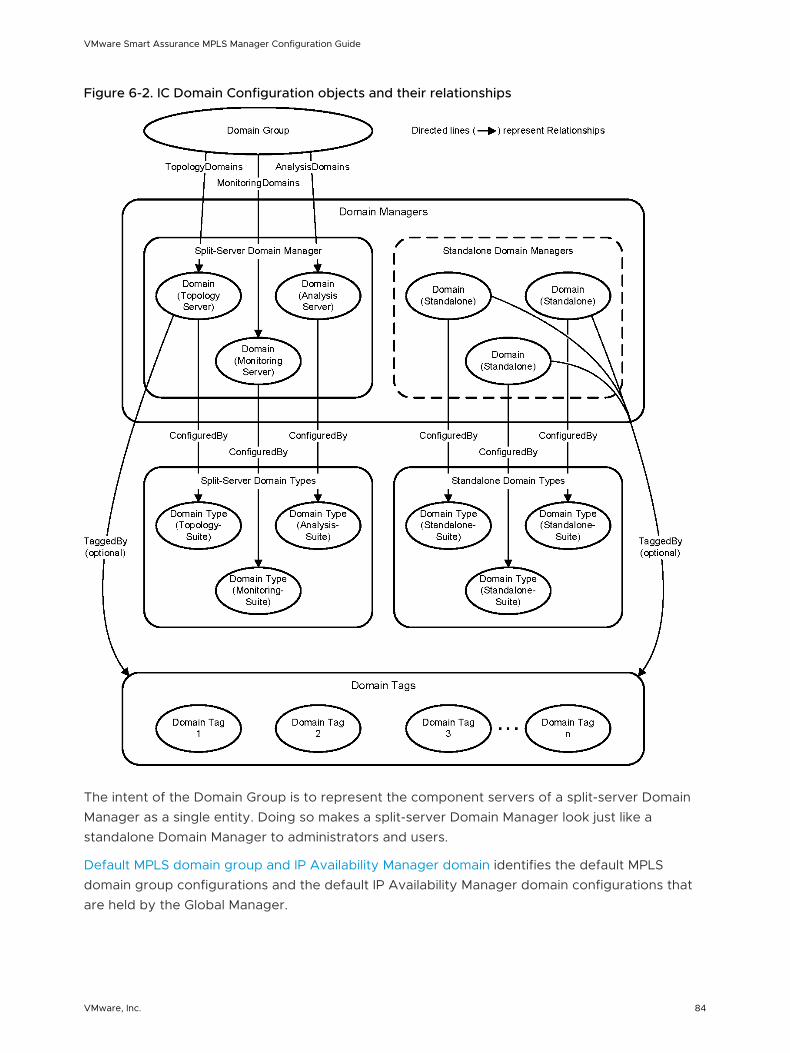
Figure 6-2. IC Domain Configuration objects and their relationships
The intent of the Domain Group is to represent the component servers of a split-server Domain Manager as a single entity. Doing so makes a split-server Domain Manager look just like a standalone Domain Manager to administrators and users.
Default MPLS domain group and IP Availability Manager domain identifies the default MPLS domain group configurations and the default IP Availability Manager domain configurations that are held by the Global Manager.
VMware Smart Assurance MPLS Manager Configuration Guide
VMware, Inc. 84
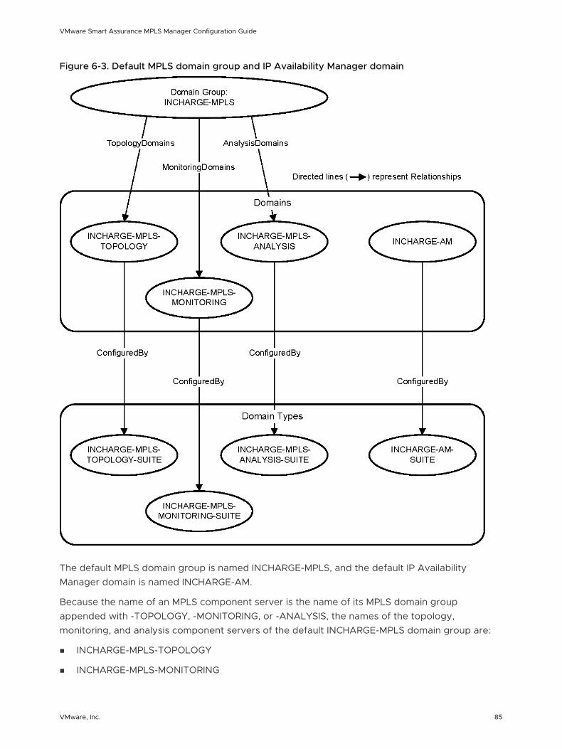
Figure 6-3. Default MPLS domain group and IP Availability Manager domain
The default MPLS domain group is named INCHARGE-MPLS, and the default IP Availability Manager domain is named INCHARGE-AM.
Because the name of an MPLS component server is the name of its MPLS domain group appended with -TOPOLOGY, -MONITORING, or -ANALYSIS, the names of the topology, monitoring, and analysis component servers of the default INCHARGE-MPLS domain group are:
n INCHARGE-MPLS-TOPOLOGY
n INCHARGE-MPLS-MONITORING
VMware Smart Assurance MPLS Manager Configuration Guide
VMware, Inc. 85
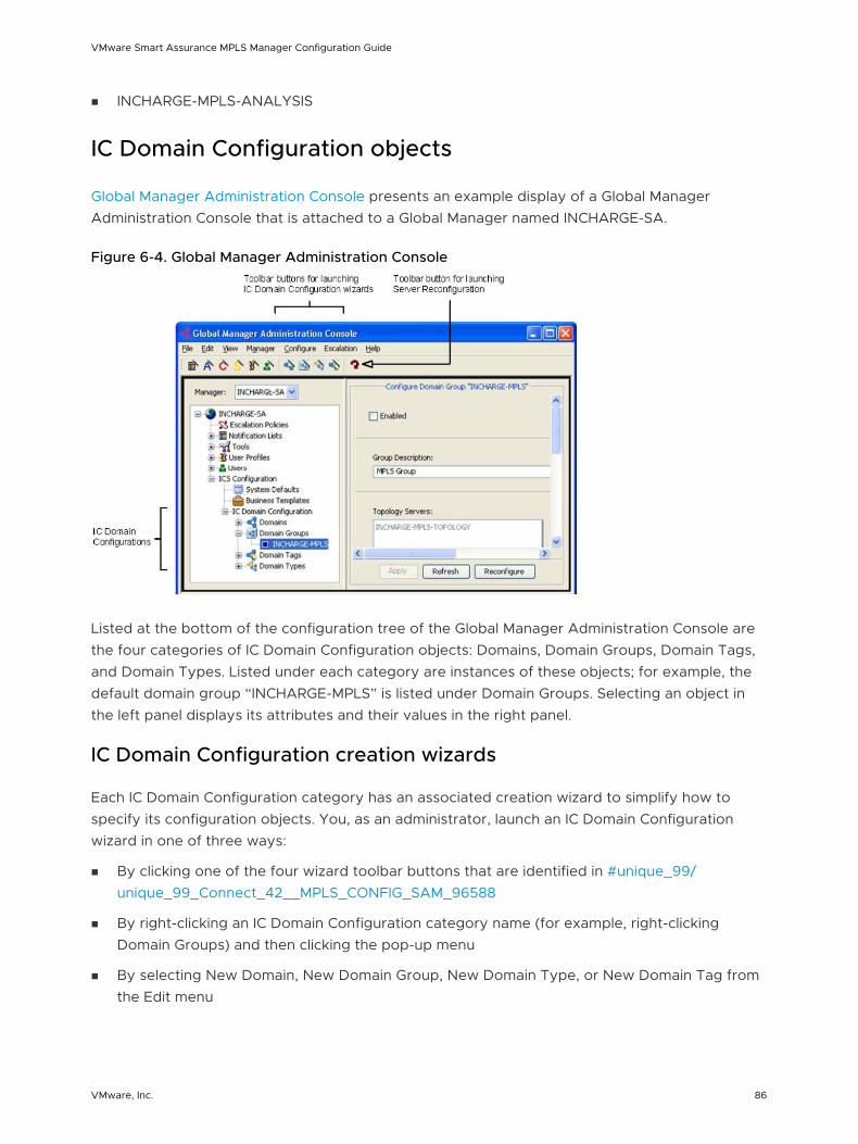
n INCHARGE-MPLS-ANALYSIS
IC Domain Configuration objects
Global Manager Administration Console presents an example display of a Global Manager Administration Console that is attached to a Global Manager named INCHARGE-SA.
Figure 6-4. Global Manager Administration Console
Listed at the bottom of the configuration tree of the Global Manager Administration Console are the four categories of IC Domain Configuration objects: Domains, Domain Groups, Domain Tags, and Domain Types. Listed under each category are instances of these objects; for example, the default domain group “INCHARGE-MPLS” is listed under Domain Groups. Selecting an object in the left panel displays its attributes and their values in the right panel.
IC Domain Configuration creation wizards
Each IC Domain Configuration category has an associated creation wizard to simplify how to specify its configuration objects. You, as an administrator, launch an IC Domain Configuration wizard in one of three ways:
n By clicking one of the four wizard toolbar buttons that are identified in #unique_99/unique_99_Connect_42__MPLS_CONFIG_SAM_96588
n By right-clicking an IC Domain Configuration category name (for example, right-clicking Domain Groups) and then clicking the pop-up menu
n By selecting New Domain, New Domain Group, New Domain Type, or New Domain Tag from the Edit menu
VMware Smart Assurance MPLS Manager Configuration Guide
VMware, Inc. 86
When you create a domain group, the created domain group and its component server domains are enabled automatically. Similarly, when you create a domain, the created domain is enabled automatically.
IC Domain Configuration server reconfiguration
Clicking the Apply button, which is available to all configuration categories, writes configuration changes to the Global Manager’s repository.
Clicking the Reconfigure button, which is available only to the IC Domain Configuration categories, calls a “reconfigure” method that determines which underlying domains need to be synchronized or resynchronized (that is, determines from which underlying domains topology or events need to be imported or reimported) and then initiates the needed data transfers. Calling the reconfigure method is referred to as “reconfiguring the Global Manager.”
In addition to clicking the Reconfigure button, the reconfigure method can be initiated in two other ways:
n By clicking the Reconfigure toolbar button that is identified in #unique_100/unique_100_Connect_42__MPLS_CONFIG_SAM_96588
n By selecting Reconfigure Server from the Configure menu
How reconfiguring the Global Manager works demonstrates how reconfiguring the Global Manager works.
VMware Smart Assurance MPLS Manager Configuration Guide
VMware, Inc. 87
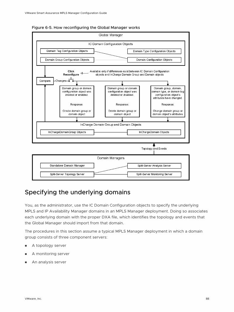
Figure 6-5. How reconfiguring the Global Manager works
Specifying the underlying domains
You, as the administrator, use the IC Domain Configuration objects to specify the underlying MPLS and IP Availability Manager domains in an MPLS Manager deployment. Doing so associates each underlying domain with the proper DXA file, which identifies the topology and events that the Global Manager should import from that domain.
The procedures in this section assume a typical MPLS Manager deployment in which a domain group consists of three component servers:
n A topology server
n A monitoring server
n An analysis server
VMware Smart Assurance MPLS Manager Configuration Guide
VMware, Inc. 88
The expectation is that an administrator will either accept the default MPLS domain group named INCHARGE-MPLS, or make a copy of the default MPLS domain group to create a new MPLS domain group that has a different name. For example, you might make a copy of INCHARGE-MPLS and name it ASIA-MPLS.
This section provides procedures for the following two configuration scenarios:
n Configuration scenario 1: An MPLS Manager deployment that contains:
n An MPLS domain group named INCHARGE-MPLS.
n An IP Availability Manager named INCHARGE-AM.
n Configuration scenario 2: An MPLS Manager deployment that contains:
n An MPLS domain group named ASIA-MPLS.
n An IP Availability Manager named ASIA-AM1.
n An IP Availability Manager named ASIA-AM2.
To specify the underlying domains in a more complex MPLS Manager deployment, consult the VMware Smart Assurance Service Assurance Manager Configuration Guide.
Specifying the underlying domains for configuration scenario 1
By default, INCHARGE-MPLS-TOPOLOGY, INCHARGE-MPLS-MONITORING, and INCHARGE-MPLS-ANALYSIS are disabled. Also, by default, INCHARGE-AM is enabled. The names of disabled domains appear as gray text in the Global Manager Administration Console, and the names of enabled domains appear as black text.
Before and after completing configuration scenario 1 previews the configuration changes for configuration scenario 1. Enabling a domain group enables all of its component server domains.
VMware Smart Assurance MPLS Manager Configuration Guide
VMware, Inc. 89
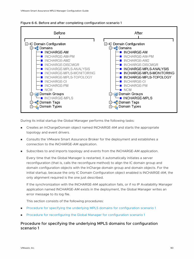
Figure 6-6. Before and after completing configuration scenario 1
During its initial startup the Global Manager performs the following tasks:
n Creates an InChargeDomain object named INCHARGE-AM and starts the appropriate topology and event drivers.
n Consults the VMware Smart Assurance Broker for the deployment and establishes a connection to the INCHARGE-AM application.
n Subscribes to and imports topology and events from the INCHARGE-AM application.
Every time that the Global Manager is restarted, it automatically initiates a server reconfiguration (that is, calls the reconfigure method) to align the IC domain group and domain configuration objects with the InCharge domain group and domain objects. For the initial startup, because the only IC Domain Configuration object enabled is INCHARGE-AM, the only alignment required is the one just described.
If the synchronization with the INCHARGE-AM application fails, or if no IP Availability Manager application named INCHARGE-AM exists in the deployment, the Global Manager writes an error message to its log file.
This section consists of the following procedures:
n Procedure for specifying the underlying MPLS domains for configuration scenario 1
n Procedure for reconfiguring the Global Manager for configuration scenario 1
Procedure for specifying the underlying MPLS domains for configuration scenario 1
VMware Smart Assurance MPLS Manager Configuration Guide
VMware, Inc. 90
To specify the underlying MPLS domains for configuration scenario 1:
1 Attach the Global Manager Administration Console to the target Global Manager.
Instructions for opening the Global Manager Administration Console are presented in Chapter 4 Opening the Global Console
2 In the left panel of the Global Manager Administration Console, expand the configuration tree to display the Domain Groups.
3 Select the INCHARGE-MPLS domain group to display its configuration window.
4 In the configuration window, click the Enabled checkbox.
5 In the configuration window, click Apply to save your configuration changes.
6 In the Server Reconfiguration information dialog box that appears, click OK.
Procedure for reconfiguring the Global Manager for configuration scenario 1
To reconfigure the Global Manager for configuration scenario 1:
1 In the toolbar area of the Global Manager Administration Console, click the Reconfigure toolbar button.
2 In the Server Reconfiguration confirmation dialog box that appears, click Yes.
3 In the Server Reconfiguration information dialog box that appears, click Close.
In response, the Global Manager:
n Creates an InChargeDomainGroup object named INCHARGE-MPLS.
n Creates an InChargeDomain object named INCHARGE-MPLS-TOPOLOGY and starts the appropriate topology drivers.
n Creates an InChargeDomain object named INCHARGE-MPLS-MONITORING and starts the appropriate topology and event drivers.
n Creates an InChargeDomain object named INCHARGE-MPLS-ANALYSIS and starts the appropriate event drivers.
n Consults the VMware Smart Assurance Broker for the deployment and establishes connections to the INCHARGE-MPLS-TOPOLOGY, INCHARGE-MPLS-MONITORING, and INCHARGE-MPLS-ANALYSIS domains.
n Subscribes to and imports topology from the INCHARGE-MPLS-TOPOLOGY domain.
n Subscribes to and imports remote ping events from the INCHARGE-MPLS-MONITORING domain.
n Subscribes to and imports events from the INCHARGE-MPLS-ANALYSIS domain.
The Global Manager will establish an additional connection to the INCHARGE-MPLS-MONITORING domain under any of the following circumstances:
VMware Smart Assurance MPLS Manager Configuration Guide
VMware, Inc. 91
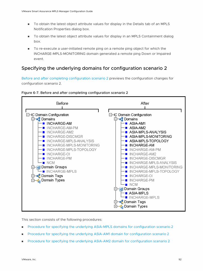
n To obtain the latest object attribute values for display in the Details tab of an MPLS Notification Properties dialog box.
n To obtain the latest object attribute values for display in an MPLS Containment dialog box.
n To re-execute a user-initiated remote ping on a remote ping object for which the INCHARGE-MPLS-MONITORING domain generated a remote ping Down or Impaired event.
Specifying the underlying domains for configuration scenario 2
Before and after completing configuration scenario 2 previews the configuration changes for configuration scenario 2.
Figure 6-7. Before and after completing configuration scenario 2
This section consists of the following procedures:
n Procedure for specifying the underlying ASIA-MPLS domains for configuration scenario 2
n Procedure for specifying the underlying ASIA-AM1 domain for configuration scenario 2
n Procedure for specifying the underlying ASIA-AM2 domain for configuration scenario 2
VMware Smart Assurance MPLS Manager Configuration Guide
VMware, Inc. 92
n Procedure for reconfiguring the Global Manager for configuration scenario 2
Procedure for specifying the underlying ASIA-MPLS domains for configuration scenario 2
To specify the underlying ASIA-MPLS domains for configuration scenario 2:
1 Attach the Global Manager Administration Console to the target Global Manager.
Instructions for opening the Global Manager Administration Console are presented in Chapter 4 Opening the Global Console
2 In the left panel of the Global Manager Administration Console, right-click Domain Groups and then click the pop-up menu to launch the Domain Group Creation Wizard.
3 Consult #unique_106/unique_106_Connect_42__MPLS_CONFIG_SAM_57786 and follow the directions to create an MPLS domain group named ASIA-MPLS.
Creating the ASIA-MPLS domain group automatically creates the following component server domains:
n ASIA-MPLS-TOPOLOGY
n ASIA-MPLS-MONITORING
n ASIA-MPLS-ANALYSIS
Procedure for specifying the underlying ASIA-AM1 domain for configuration scenario 2
To specify the underlying ASIA-AM1 domain for configuration scenario 2:
1 In the left panel of the Global Manager Administration Console, right-click Domains and then click the pop-up menu to launch the Domain Creation Wizard.
2 Consult #unique_107/unique_107_Connect_42__MPLS_CONFIG_SAM_67286 and follow the directions to create an IP Availability Manager domain named ASIA-AM1.
Procedure for specifying the underlying ASIA-AM2 domain for configuration scenario 2
To specify the underlying ASIA-AM2 domain for configuration scenario 2:
1 In the left panel of the Global Manager Administration Console, right-click Domains and then click the pop-up menu to launch the Domain Creation Wizard.
2 Consult Using the Domain Creation Wizard to create the ASIA-AM1 domain and use the directions as a guide to create an IP Availability Manager domain named ASIA-AM2.
VMware Smart Assurance MPLS Manager Configuration Guide
VMware, Inc. 93
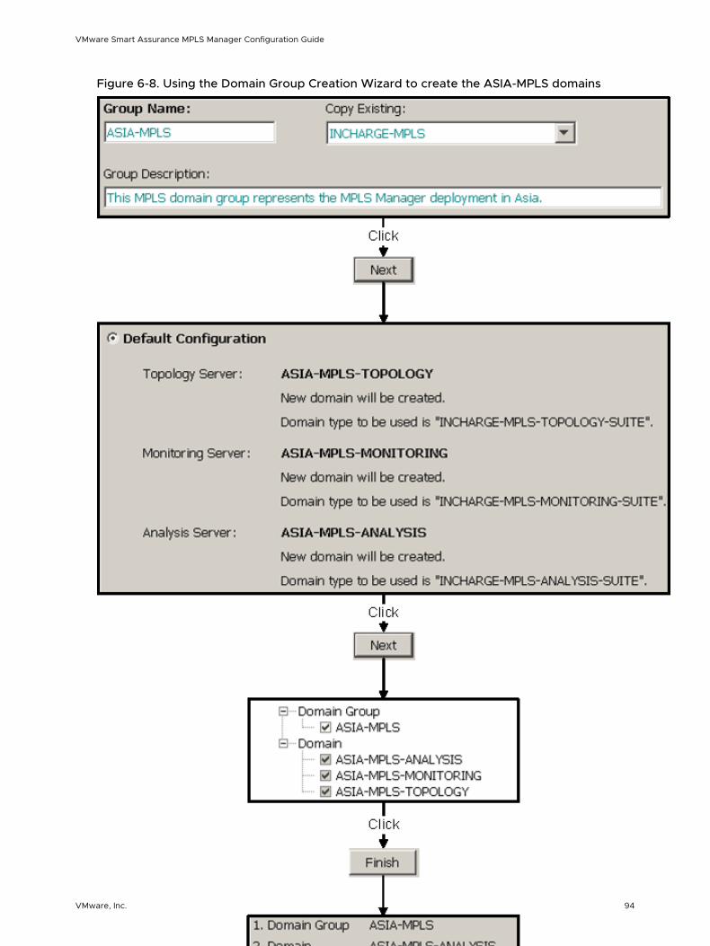
Figure 6-8. Using the Domain Group Creation Wizard to create the ASIA-MPLS domains
VMware Smart Assurance MPLS Manager Configuration Guide
VMware, Inc. 94
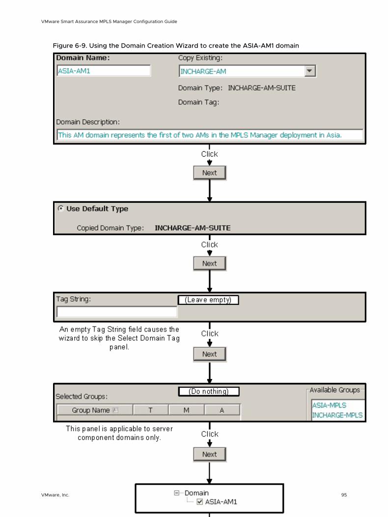
Figure 6-9. Using the Domain Creation Wizard to create the ASIA-AM1 domain
VMware Smart Assurance MPLS Manager Configuration Guide
VMware, Inc. 95
Procedure for reconfiguring the Global Manager for configuration scenario 2
To reconfigure the Global Manager for configuration scenario 2:
1 In the toolbar area of the Global Manager Administration Console, click the Reconfigure toolbar button.
2 In the Server Reconfiguration confirmation dialog box, click Yes.
3 In the Server Reconfiguration information dialog box, click Close.
In response, the Global Manager:
n Creates an InChargeDomainGroup object named ASIA-MPLS.
n Creates an InChargeDomain object named ASIA-MPLS-TOPOLOGY and starts the appropriate topology drivers.
n Creates an InChargeDomain object named ASIA-MPLS-MONITORING and starts the appropriate topology and event drivers.
n Creates an InChargeDomain object named ASIA-MPLS-ANALYSIS and starts the appropriate event drivers.
n Creates an InChargeDomain object named ASIA-AM1 and starts the appropriate topology and event drivers.
n Creates an InChargeDomain object named ASIA-AM2 and starts the appropriate topology and event drivers.
n Consults the VMware Smart Assurance Broker for the deployment and establishes connections to the ASIA-MPLS-TOPOLOGY, ASIA-MPLS-MONITORING, ASIA-MPLS-ANALYSIS, ASIA-AM1, and ASIA-AM2 domains.
n Subscribes to and imports topology from the ASIA-MPLS-TOPOLOGY domain.
n Subscribes to and imports remote ping events from the ASIA-MPLS-MONITORING domain.
n Subscribes to and imports events from the ASIA-MPLS-ANALYSIS domain.
n Subscribes to and imports topology and events from the ASIA-AM1 domain.
n Subscribes to and imports topology and events from the ASIA-AM2 domain.
The Global Manager will establish an additional connection to the ASIA-MPLS-MONITORING domain under any of the following circumstances:
n To obtain the latest object attribute values for display in the Details tab of an MPLS Notification Properties dialog box.
n To obtain the latest object attribute values for display in an MPLS Containment dialog box.
VMware Smart Assurance MPLS Manager Configuration Guide
VMware, Inc. 96
n To re-execute a user-initiated remote ping on a remote ping object for which the ASIA-MPLS-MONITORING domain generated a remote ping Down or Impaired event.
Note As no IP Availability Manager application named INCHARGE-AM is running in configuration scenario 2, the administrator should disable the INCHARGE-AM domain for this scenario.
Enabling the display of MPLS maps
As described in the VMware Smart Assurance MPLS Management Suite User Guide, you can use topology maps to view graphical representations of the MPLS, VPN, and other topology that is imported by the Global Manager. By default, the display of these maps is disabled.
To enable the display of MPLS and other optional map types and to associate their functionality to user profiles:
1 Attach the Global Manager Administration Console to the target Global Manager.
Instructions for opening the Global Manager Administration Console are presented in Chapter 4 Opening the Global Console
2 In the left panel of the Global Manager Administration Console, expand the configuration tree to display the User Profiles.
3 Select a user profile (for example, admin-profile) to display its configuration window.
4 In the configuration window, locate Console Operations and click its Modify List button to launch the Console Operations dialog box.
5 In the Console Operations dialog box, expand the Map option and click the MPLS Connectivity checkbox.
6 If MPLS-BGP cross-domain correlation is enabled, click the BGP Connectivity checkbox.
7 If NG MVPNs are included in the managed environment, click the Multicast Connectivity checkbox.
8 Click OK to close the Console Operations dialog box.
9 In the configuration window, click Apply to save your configuration changes.
10 Repeat Steps 3 through 10 to enable the display of MPLS and other optional map types for any other user profiles that need to see these maps.
11 Detach and reattach the Global Console to the Global Manager in order to view the MPLS topology maps. Start by selecting Manager > Detach.
Enabling the use of MPLS remote ping and LSP ping server tools
VMware Smart Assurance MPLS Manager Configuration Guide
VMware, Inc. 97
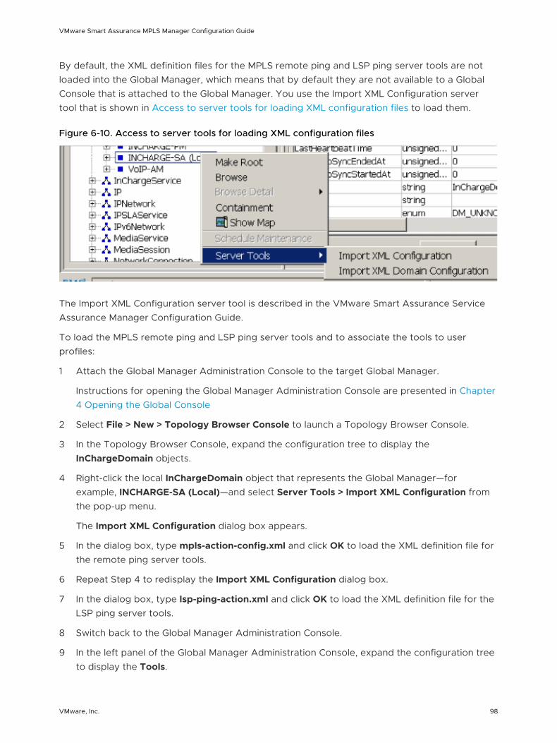
By default, the XML definition files for the MPLS remote ping and LSP ping server tools are not loaded into the Global Manager, which means that by default they are not available to a Global Console that is attached to the Global Manager. You use the Import XML Configuration server tool that is shown in Access to server tools for loading XML configuration files to load them.
Figure 6-10. Access to server tools for loading XML configuration files
The Import XML Configuration server tool is described in the VMware Smart Assurance Service Assurance Manager Configuration Guide.
To load the MPLS remote ping and LSP ping server tools and to associate the tools to user profiles:
1 Attach the Global Manager Administration Console to the target Global Manager.
Instructions for opening the Global Manager Administration Console are presented in Chapter 4 Opening the Global Console
2 Select File > New > Topology Browser Console to launch a Topology Browser Console.
3 In the Topology Browser Console, expand the configuration tree to display the InChargeDomain objects.
4 Right-click the local InChargeDomain object that represents the Global Manager—for example, INCHARGE-SA (Local)—and select Server Tools > Import XML Configuration from the pop-up menu.
The Import XML Configuration dialog box appears.
5 In the dialog box, type mpls-action-config.xml and click OK to load the XML definition file for the remote ping server tools.
6 Repeat Step 4 to redisplay the Import XML Configuration dialog box.
7 In the dialog box, type lsp-ping-action.xml and click OK to load the XML definition file for the LSP ping server tools.
8 Switch back to the Global Manager Administration Console.
9 In the left panel of the Global Manager Administration Console, expand the configuration tree to display the Tools.
VMware Smart Assurance MPLS Manager Configuration Guide
VMware, Inc. 98
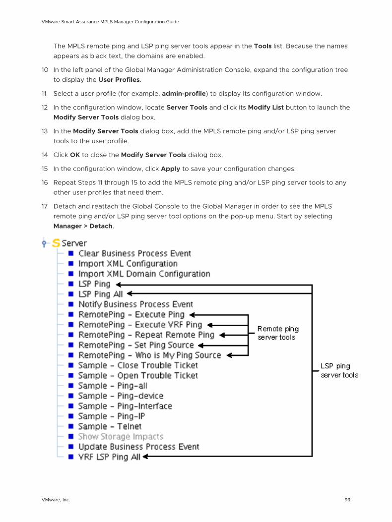
The MPLS remote ping and LSP ping server tools appear in the Tools list. Because the names appears as black text, the domains are enabled.
10 In the left panel of the Global Manager Administration Console, expand the configuration tree to display the User Profiles.
11 Select a user profile (for example, admin-profile) to display its configuration window.
12 In the configuration window, locate Server Tools and click its Modify List button to launch the Modify Server Tools dialog box.
13 In the Modify Server Tools dialog box, add the MPLS remote ping and/or LSP ping server tools to the user profile.
14 Click OK to close the Modify Server Tools dialog box.
15 In the configuration window, click Apply to save your configuration changes.
16 Repeat Steps 11 through 15 to add the MPLS remote ping and/or LSP ping server tools to any other user profiles that need them.
17 Detach and reattach the Global Console to the Global Manager in order to see the MPLS remote ping and/or LSP ping server tool options on the pop-up menu. Start by selecting Manager > Detach.
VMware Smart Assurance MPLS Manager Configuration Guide
VMware, Inc. 99
Enabling the subscription of remote ping down and impaired events
By default, the Global Manager subscribes to the VPN ImpactedByRemotePingFailure event for periodic remote pings but not to the following events for periodic remote pings:
n RemotePing Down
n RemotePing Impaired
You can edit the dxa-mpls-vpn-ics-monitoring.conf file and enable the subscription of these two events. The line to be edited is:
#sub RemotePing::.*::.*/e
To enable the subscription of remote ping down and impaired events:
a Go to the BASEDIR/smarts/bin directory in the Global Manager installation area and type the following command to open the dxa-mpls-vpn-ics-monitoring.conf file:
sm_edit conf/ics/dxa-mpls-vpn-ics-monitoring.conf
b Find the following line in the file:
#sub RemotePing::.*::.*/e
c Uncomment the line by removing the # character.
d Save and close the file.
The modified version of the dxa-mpls-vpn-ics-monitoring.conf file is saved to the BASEDIR/smarts/local/conf/ics directory.
e If the Global Manager was running before you edited the dxa-mpls-vpn-ics-monitoring.conf file, restart the Global Manager.
Changing LSP ping global values
By default, the command options that are shown in Default LSP ping command lines invoked for LSP ping server tool invocations are included in the LSP ping command lines that are created for LSP ping server tool invocations.
VMware Smart Assurance MPLS Manager Configuration Guide
VMware, Inc. 100
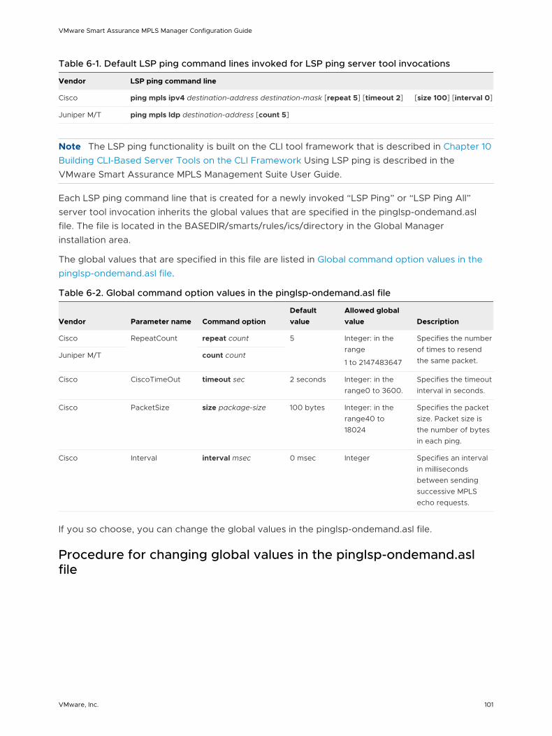
Table 6-1. Default LSP ping command lines invoked for LSP ping server tool invocations
Vendor LSP ping command line
Cisco ping mpls ipv4 destination-address destination-mask [repeat 5] [timeout 2] [size 100] [interval 0]
Juniper M/T ping mpls ldp destination-address [count 5]
Note The LSP ping functionality is built on the CLI tool framework that is described in Chapter 10 Building CLI-Based Server Tools on the CLI Framework Using LSP ping is described in the VMware Smart Assurance MPLS Management Suite User Guide.
Each LSP ping command line that is created for a newly invoked “LSP Ping” or “LSP Ping All” server tool invocation inherits the global values that are specified in the pinglsp-ondemand.asl file. The file is located in the BASEDIR/smarts/rules/ics/directory in the Global Manager installation area.
The global values that are specified in this file are listed in Global command option values in the pinglsp-ondemand.asl file.
Table 6-2. Global command option values in the pinglsp-ondemand.asl file
Vendor Parameter name Command optionDefault value
Allowed global value Description
Cisco RepeatCount repeat count 5 Integer: in the range
1 to 2147483647
Specifies the number of times to resend the same packet.
Juniper M/T count count
Cisco CiscoTimeOut timeout sec 2 seconds Integer: in the range0 to 3600.
Specifies the timeout interval in seconds.
Cisco PacketSize size package-size 100 bytes Integer: in the range40 to 18024
Specifies the packet size. Packet size is the number of bytes in each ping.
Cisco Interval interval msec 0 msec Integer Specifies an interval in milliseconds between sending successive MPLS echo requests.
If you so choose, you can change the global values in the pinglsp-ondemand.asl file.
Procedure for changing global values in the pinglsp-ondemand.asl file
VMware Smart Assurance MPLS Manager Configuration Guide
VMware, Inc. 101
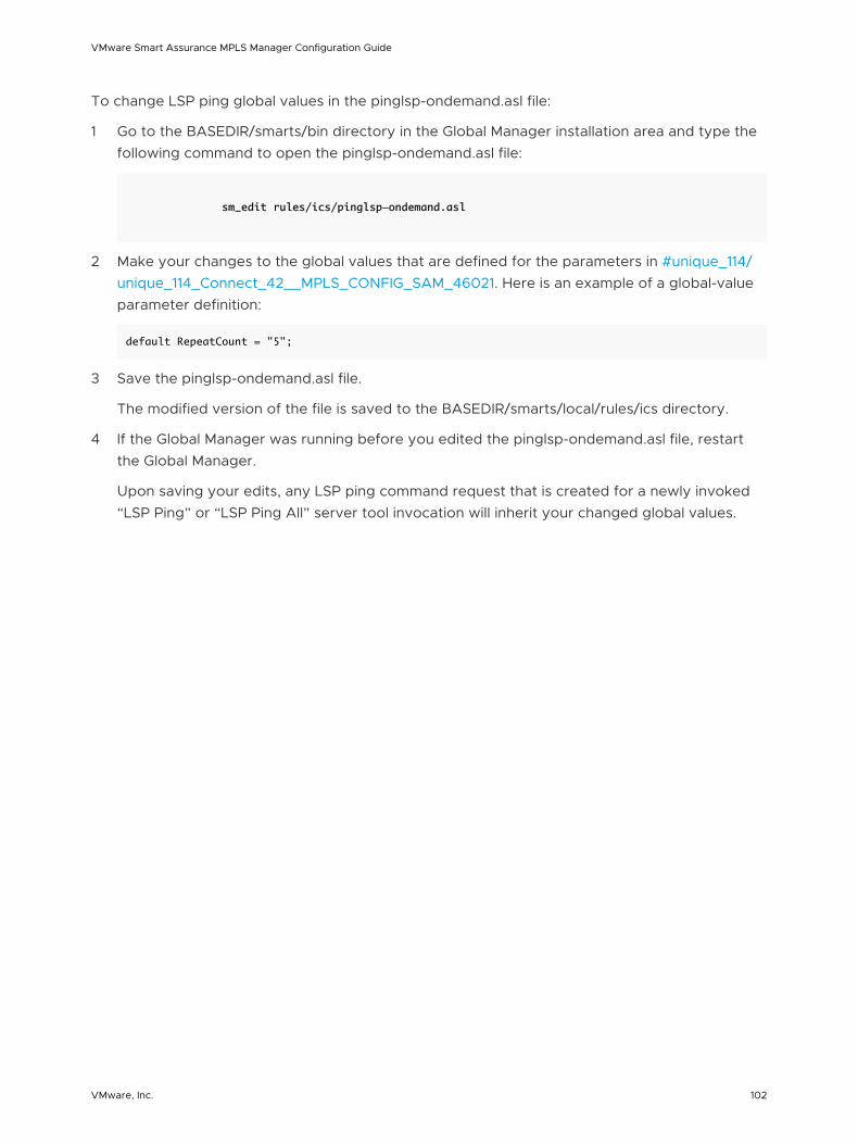
To change LSP ping global values in the pinglsp-ondemand.asl file:
1 Go to the BASEDIR/smarts/bin directory in the Global Manager installation area and type the following command to open the pinglsp-ondemand.asl file:
sm_edit rules/ics/pinglsp-ondemand.asl
2 Make your changes to the global values that are defined for the parameters in #unique_114/unique_114_Connect_42__MPLS_CONFIG_SAM_46021. Here is an example of a global-value parameter definition:
default RepeatCount = "5";
3 Save the pinglsp-ondemand.asl file.
The modified version of the file is saved to the BASEDIR/smarts/local/rules/ics directory.
4 If the Global Manager was running before you edited the pinglsp-ondemand.asl file, restart the Global Manager.
Upon saving your edits, any LSP ping command request that is created for a newly invoked “LSP Ping” or “LSP Ping All” server tool invocation will inherit your changed global values.
VMware Smart Assurance MPLS Manager Configuration Guide
VMware, Inc. 102
Configuring SSH or Telnet Remote Access 7This chapter includes the following topics:
n SSH and Telnet overview
n SSH and Telnet support
n SSH1 and SSH2
n SSH authentication
n SSH client requirements
n SSH client and SSH server configuration files
n SSH client configuration
n SSH server configuration
SSH and Telnet overview
Like Telnet, SSH is a network protocol for logging in to a remote host and executing commands on the remote host. Unlike Telnet, SSH uses special algorithms to encrypt the data stream, to ensure data stream integrity, and even to perform authentication in a safe and secure way. SSH is a secure, encrypted replacement for Telnet. Both SSH and Telnet provide access to a command line interface (CLI) on a remote host.
In an MPLS Manager deployment, the MPLS Topology Server uses SSH CLI or Telnet CLI for two purposes:
n To query MPLS-enabled devices for topology information.
n To execute on-demand LSP ping requests.
SSH and Telnet support
Two independent CLI remote-access packages are available in MPLS Manager:
n SSH-Telnet CLI package
VMware, Inc. 103
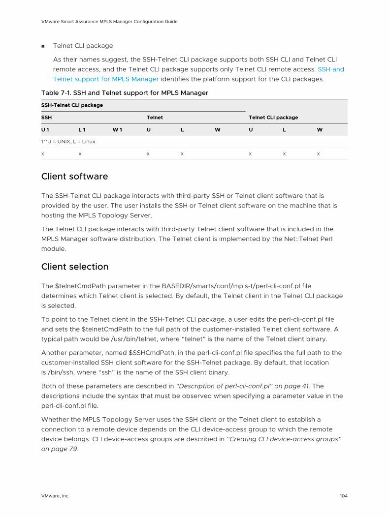
n Telnet CLI package
As their names suggest, the SSH-Telnet CLI package supports both SSH CLI and Telnet CLI remote access, and the Telnet CLI package supports only Telnet CLI remote access. SSH and Telnet support for MPLS Manager identifies the platform support for the CLI packages.
Table 7-1. SSH and Telnet support for MPLS Manager
SSH-Telnet CLI package
Telnet CLI packageSSH Telnet
U 1 L 1 W 1 U L W U L W
1**U = UNIX, L = Linux
x x x x x x x
Client software
The SSH-Telnet CLI package interacts with third-party SSH or Telnet client software that is provided by the user. The user installs the SSH or Telnet client software on the machine that is hosting the MPLS Topology Server.
The Telnet CLI package interacts with third-party Telnet client software that is included in the MPLS Manager software distribution. The Telnet client is implemented by the Net::Telnet Perl module.
Client selection
The $telnetCmdPath parameter in the BASEDIR/smarts/conf/mpls-t/perl-cli-conf.pl file determines which Telnet client is selected. By default, the Telnet client in the Telnet CLI package is selected.
To point to the Telnet client in the SSH-Telnet CLI package, a user edits the perl-cli-conf.pl file and sets the $telnetCmdPath to the full path of the customer-installed Telnet client software. A typical path would be /usr/bin/telnet, where “telnet” is the name of the Telnet client binary.
Another parameter, named $SSHCmdPath, in the perl-cli-conf.pl file specifies the full path to the customer-installed SSH client software for the SSH-Telnet package. By default, that location is /bin/ssh, where “ssh” is the name of the SSH client binary.
Both of these parameters are described in “Description of perl-cli-conf.pl” on page 41. The descriptions include the syntax that must be observed when specifying a parameter value in the perl-cli-conf.pl file.
Whether the MPLS Topology Server uses the SSH client or the Telnet client to establish a connection to a remote device depends on the CLI device-access group to which the remote device belongs. CLI device-access groups are described in “Creating CLI device-access groups” on page 79.
VMware Smart Assurance MPLS Manager Configuration Guide
VMware, Inc. 104
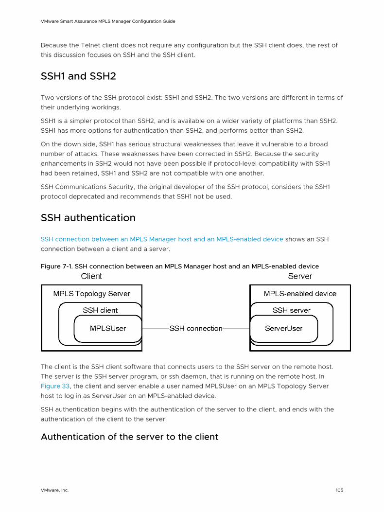
Because the Telnet client does not require any configuration but the SSH client does, the rest of this discussion focuses on SSH and the SSH client.
SSH1 and SSH2
Two versions of the SSH protocol exist: SSH1 and SSH2. The two versions are different in terms of their underlying workings.
SSH1 is a simpler protocol than SSH2, and is available on a wider variety of platforms than SSH2. SSH1 has more options for authentication than SSH2, and performs better than SSH2.
On the down side, SSH1 has serious structural weaknesses that leave it vulnerable to a broad number of attacks. These weaknesses have been corrected in SSH2. Because the security enhancements in SSH2 would not have been possible if protocol-level compatibility with SSH1 had been retained, SSH1 and SSH2 are not compatible with one another.
SSH Communications Security, the original developer of the SSH protocol, considers the SSH1 protocol deprecated and recommends that SSH1 not be used.
SSH authentication
SSH connection between an MPLS Manager host and an MPLS-enabled device shows an SSH connection between a client and a server.
Figure 7-1. SSH connection between an MPLS Manager host and an MPLS-enabled device
The client is the SSH client software that connects users to the SSH server on the remote host. The server is the SSH server program, or ssh daemon, that is running on the remote host. In Figure 33, the client and server enable a user named MPLSUser on an MPLS Topology Server host to log in as ServerUser on an MPLS-enabled device.
SSH authentication begins with the authentication of the server to the client, and ends with the authentication of the client to the server.
Authentication of the server to the client
VMware Smart Assurance MPLS Manager Configuration Guide
VMware, Inc. 105
When the client issues an SSH connection request, such as ssh ServerUser@remotesystem, the server accepts the connection request and responds with the server’s version identification. The client parses the server’s version identification and then sends its own version identification. The purpose of the version-identification exchange is three-fold:
n To validate that the connection is to the correct server port.
Note The standard SSH port is 22.
n To declare the SSH protocol version number that is used by the server and by the client.
n To declare the software version that is used by the server and by the client.
The client and server negotiate which SSH protocol version to use.
The server then sends its public host key and a list of supported ciphers and authentication methods to the client. The client compares the server’s host key to the user’s database of known hosts. If the received host key matches the server’s host key entry in the user’s database, the SSH connection attempt continues.
If the received host key does not match the server’s host key entry, the client terminates the SSH connection attempt, and informs the user where to find the conflicting key in the user’s database.
If no host key entry exists for the server in the user’s database, the client responds in one of three ways, depending on the value of the StrictHostKeyChecking parameter in the client’s configuration file:
n StrictHostKeyChecking=ask (default)
The client asks the user whether to add the server’s host key to the user’s database.
If the user answers with yes, the client adds the server’s host key to the user’s database and continues the SSH connection attempt.
If the user answers with no, the client discards the server’s host key and terminates the SSH connection attempt.
n StrictHostKeyChecking=no
The client automatically adds the server’s host key to the user’s database and continues the SSH connection attempt.
n StrictHostKeyChecking=yes
The client discards the server’s host key and terminates the SSH connection attempt.
If the outcome is that the SSH connection attempt should continue, server authentication is established.
The client then generates a session key, encrypts it with the server’s host key, and sends the encrypted session key and selected cipher to the server. Both sides then turn on encryption using the session key and the selected cipher. The server sends an encrypted confirmation message to the client.
VMware Smart Assurance MPLS Manager Configuration Guide
VMware, Inc. 106
Authentication of the client to the server
To authenticate the client to the server, the client may use any of the methods in the list of authentication methods received from the server. Three well-known authentication methods are:
n Password authentication
Password authentication uses the password of the username account (ServerUser, for example) on the remote host to perform client authentication.
With this method, the user enters the password, and the client encrypts and transmits the password. The server receives and decrypts the password, and the remote host authenticates the password against its password database.
n Public-key authentication
Public-key authentication uses public/private key pairs to perform client authentication, without the need to transmit a password over the network. A user creates a public/private key pair for authentication purposes. The server knows the user’s public key, and only the user has the private key.
With this method, the server generates a random number, uses the user’s public key to encrypt the number, and sends the encrypted number to the client. The client uses the user’s private key to decrypt the number and sends the number back to the server.
n Host-based authentication
Host authentication uses the client’s hostname and the user’s username (NPMUser, for example) on the remote host to perform client authentication.
With this method, the client sends a signature that is created with the user’s private key, and the server verifies the signature with the user’s public key. When the user’s identity is established, authorization is performed based on (1) the client’s hostname and (2) the user’s username on both the server and the client.
When the user’s identity has been accepted by the server, the server logs in to the remote host and gives the user a normal shell on the remote host. All CLI commands and responses with/from the remote shell will be encrypted.
SSH client requirements
The SSH-Telnet CLI package supports two SSH client authentication methods:
n Password authentication
n Public-key authentication
The SSH-Telnet CLI package requires an SSH client that is comparable to the SSH client in OpenSSH 2.0 or higher. The OpenSSH 2.0 client supports SSH protocol versions 1.3, 1.5, and 2.0.
VMware Smart Assurance MPLS Manager Configuration Guide
VMware, Inc. 107
An SSH client that is comparable to the SSH client in OpenSSH 2.0 or higher supports SSH protocols 1 and 2. A typical configuration is to make protocol 2 primary, with fall back to protocol 1 if the SSH client detects that protocol 2 is not supported by the SSH server.
Both protocols support password and public-key (and other) authentication methods, but protocol 2 is preferred because it provides additional components for confidentiality and integrity. Protocol 1 lacks a strong component for ensuring the integrity of the connection.
SSH client and SSH server configuration files
For OpenSSH, the SSH client user configuration file is named config, and the SSH client system-wide configuration file is named ssh_config. The files reside at the following locations:
n User configuration file location: $HOME/.ssh/config
n System-wide configuration file default location: /etc/ssh/ssh_config
An SSH client obtains its configurations from the ssh command-line options, the user configuration file, and the system-wide configuration file, in that order. For each parameter, the SSH client uses the first obtained value for that parameter.
Because of the potential for abuse, the config file must have strict permissions: read/write for the user, and not accessible by others. From the $HOME directory, executing the following UNIX command acquires these permissions:
chmod go-rwx .ssh/*
The ssh_config file provides defaults for those values that are not specified in the config file. This file must be world-readable.
The SSH server has its own set of configuration files, including the SSH server system-wide configuration file named sshd_config. By default, these files reside in the /etc/ssh directory on the remote host.
The configuration files enable an administrator to set parameters that modify the operation of the SSH client and the SSH server.
SSH client configuration
After installing the SSH client software, you, as the MPLS Manager administrator, perform the following configuration tasks:
1 Create one or more CLI device-access groups that have the device-access method set to SSH1 or SSH2. SSH2 is recommended.
Instructions for creating CLI device-access groups are presented in “Creating CLI device-access groups” on page 79.
VMware Smart Assurance MPLS Manager Configuration Guide
VMware, Inc. 108
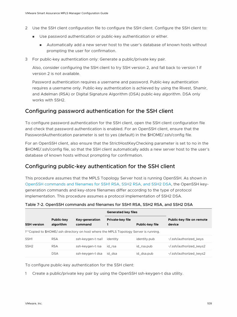
2 Use the SSH client configuration file to configure the SSH client. Configure the SSH client to:
n Use password authentication or public-key authentication or either.
n Automatically add a new server host to the user’s database of known hosts without prompting the user for confirmation.
3 For public-key authentication only: Generate a public/private key pair.
Also, consider configuring the SSH client to try SSH version 2, and fall back to version 1 if version 2 is not available.
Password authentication requires a username and password. Public-key authentication requires a username only. Public-key authentication is achieved by using the Rivest, Shamir, and Adelman (RSA) or Digital Signature Algorithm (DSA) public-key algorithm. DSA only works with SSH2.
Configuring password authentication for the SSH client
To configure password authentication for the SSH client, open the SSH client configuration file and check that password authentication is enabled. For an OpenSSH client, ensure that the PasswordAuthentication parameter is set to yes (default) in the $HOME/.ssh/config file.
For an OpenSSH client, also ensure that the StrictHostKeyChecking parameter is set to no in the $HOME/.ssh/config file, so that the SSH client automatically adds a new server host to the user’s database of known hosts without prompting for confirmation.
Configuring public-key authentication for the SSH client
This procedure assumes that the MPLS Topology Server host is running OpenSSH. As shown in OpenSSH commands and filenames for SSH1 RSA, SSH2 RSA, and SSH2 DSA, the OpenSSH key-generation commands and key-store filenames differ according to the type of protocol implementation. This procedure assumes a protocol implementation of SSH2 DSA.
Table 7-2. OpenSSH commands and filenames for SSH1 RSA, SSH2 RSA, and SSH2 DSA
SSH versionPublic-key algorithm
Key-generation command
Generated key files
Public-key file on remote device
Private-key file 1 Public-key file
1**Copied to $HOME/.ssh directory on host where the MPLS Topology Server is running.
SSH1 RSA ssh-keygen-t rsa1 identity identity.pub ~/.ssh/authorized_keys
SSH2 RSA ssh-keygen-t rsa id_rsa id_rsa.pub ~/.ssh/authorized_keys2
DSA ssh-keygen-t dsa id_dsa id_dsa.pub ~/.ssh/authorized_keys2
To configure public-key authentication for the SSH client:
1 Create a public/private key pair by using the OpenSSH ssh-keygen-t dsa utility.
VMware Smart Assurance MPLS Manager Configuration Guide
VMware, Inc. 109
When prompted, enter a key-store file path and a passphrase. The OpenSSH ssh-keygen-t dsa utility then creates the key pair, uses the passphrase to encrypt the private key before storing the private key in the key-store file (for example, in the /home/MPLS/.ssh/id_dsa file), and stores the public key in a sibling location (for example, in the /home/MPLS/.ssh/id_dsa.pub file).
2 Copy the public key to each of the SSH-enabled devices in the managed network.
For example:
% scp ~/.ssh/id_dsa.pub ServerUser@remotesystem
3 Append the public key to the authorization file on each of the devices.
Because public-key authentication is not yet configured at the devices, you would use SSH password authentication to log in to the devices to complete this step. For example:
% ssh ServerUser@remotesystem
ServerUser@remotesystem's password: <enter password>
.
.
.
remotesystem> cat id_dsa.pub >> ~/.ssh/authorized_keys2
remotesystem> logout
If the authorization file does not exist, the administrator must create it:
remotesystem> mv id_dsa.pub ~/.ssh/authorized_keys2
remotesystem> logout
4 Open the SSH client configuration file and check that the following two parameters are configured as shown:
n PubkeyAuthentication=yes
n StrictHostKeyChecking=no
SSH server configuration
Both password authentication and public-key authentication require configuration at both the SSH client and the SSH server. Depending or who is authorized to do what, you, as the MPLS Manager administrator, might need to contact the system administrator of the network devices in the managed network to complete some of these tasks.
Configuring a network device to use SSH requires the completion of the following basic tasks for each network device that is to be SSH enabled:
n Enable the SSH transport support for the virtual-terminal connections.
VMware Smart Assurance MPLS Manager Configuration Guide
VMware, Inc. 110

n Generate a public/private key pair.
The public key of the generated public/private key pair is referred to as the “public host key” or just “host key.”
The procedure to configure the SSH server on a network device depends on the make and model of the device. Consult the device’s user documentation to complete the procedure.
VMware Smart Assurance MPLS Manager Configuration Guide
VMware, Inc. 111
Using the Polling and Thresholds Console 8This chapter introduces the Polling and Thresholds Console, defines groups and settings, and provides instructions on using the Polling and Thresholds Console to work with groups and settings.
This chapter includes the following topics:
n Opening the Polling and Thresholds Console
n Understanding groups and settings
n Working with groups and settings
Opening the Polling and Thresholds Console
The Polling and Thresholds Console is used to display groups and modify their properties. In Polling and Thresholds Console, the Polling and Thresholds Console is attached to an MPLS Topology Server named INCHARGE-MPLS-TOPOLOGY.
VMware, Inc. 112
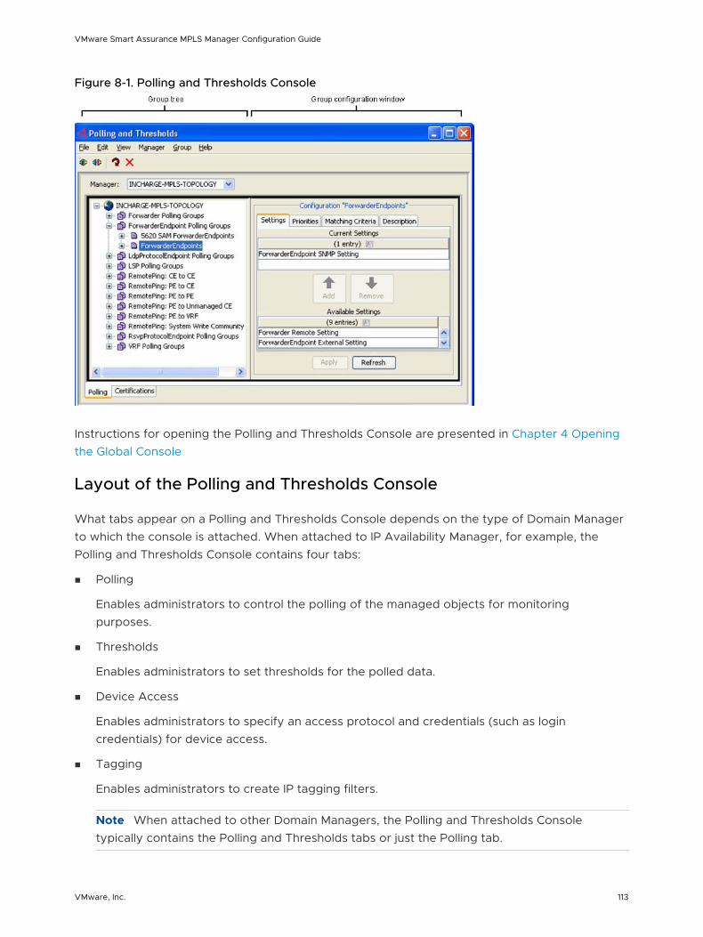
Figure 8-1. Polling and Thresholds Console
Instructions for opening the Polling and Thresholds Console are presented in Chapter 4 Opening the Global Console
Layout of the Polling and Thresholds Console
What tabs appear on a Polling and Thresholds Console depends on the type of Domain Manager to which the console is attached. When attached to IP Availability Manager, for example, the Polling and Thresholds Console contains four tabs:
n Polling
Enables administrators to control the polling of the managed objects for monitoring purposes.
n Thresholds
Enables administrators to set thresholds for the polled data.
n Device Access
Enables administrators to specify an access protocol and credentials (such as login credentials) for device access.
n Tagging
Enables administrators to create IP tagging filters.
Note When attached to other Domain Managers, the Polling and Thresholds Console typically contains the Polling and Thresholds tabs or just the Polling tab.
VMware Smart Assurance MPLS Manager Configuration Guide
VMware, Inc. 113
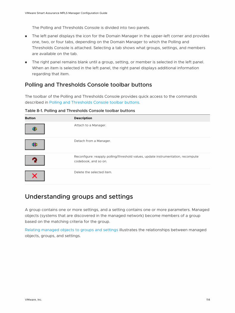
The Polling and Thresholds Console is divided into two panels.
n The left panel displays the icon for the Domain Manager in the upper-left corner and provides one, two, or four tabs, depending on the Domain Manager to which the Polling and Thresholds Console is attached. Selecting a tab shows what groups, settings, and members are available on the tab.
n The right panel remains blank until a group, setting, or member is selected in the left panel. When an item is selected in the left panel, the right panel displays additional information regarding that item.
Polling and Thresholds Console toolbar buttons
The toolbar of the Polling and Thresholds Console provides quick access to the commands described in Polling and Thresholds Console toolbar buttons.
Table 8-1. Polling and Thresholds Console toolbar buttons
Button Description
Attach to a Manager.
Detach from a Manager.
Reconfigure: reapply polling/threshold values, update instrumentation, recompute codebook, and so on.
Delete the selected item.
Understanding groups and settings
A group contains one or more settings, and a setting contains one or more parameters. Managed objects (systems that are discovered in the managed network) become members of a group based on the matching criteria for the group.
Relating managed objects to groups and settings illustrates the relationships between managed objects, groups, and settings.
VMware Smart Assurance MPLS Manager Configuration Guide
VMware, Inc. 114
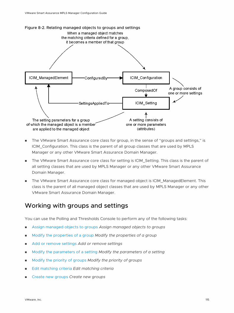
Figure 8-2. Relating managed objects to groups and settings
n The VMware Smart Assurance core class for group, in the sense of “groups and settings,” is ICIM_Configuration. This class is the parent of all group classes that are used by MPLS Manager or any other VMware Smart Assurance Domain Manager.
n The VMware Smart Assurance core class for setting is ICIM_Setting. This class is the parent of all setting classes that are used by MPLS Manager or any other VMware Smart Assurance Domain Manager.
n The VMware Smart Assurance core class for managed object is ICIM_ManagedElement. This class is the parent of all managed object classes that are used by MPLS Manager or any other VMware Smart Assurance Domain Manager.
Working with groups and settings
You can use the Polling and Thresholds Console to perform any of the following tasks:
n Assign managed objects to groups Assign managed objects to groups
n Modify the properties of a group Modify the properties of a group
n Add or remove settings Add or remove settings
n Modify the parameters of a setting Modify the parameters of a setting
n Modify the priority of groups Modify the priority of groups
n Edit matching criteria Edit matching criteria
n Create new groups Create new groups
VMware Smart Assurance MPLS Manager Configuration Guide
VMware, Inc. 115
Assign managed objects to groups
When MPLS Manager performs discovery, it automatically assigns each managed object to one or more groups based on the:
n Matching criteria for a group.
n Priority of a group, which determines membership when an object meets the matching criteria for more than one group within a particular group category.
A managed object may be a member of one and only one group within a particular group category.
Modify the properties of a group
A group’s matching criteria and priority determine which managed objects become members of the group.
When a group is selected in the left panel of the Polling and Thresholds Console, four tabs appear in the right panel of the console:
n Settings
n Priorities
n Matching Criteria
n Description
Modifying the properties in the Settings, Priorities, or Matching Criteria tab changes the configuration of the group.
When you finish editing the properties of a group, perform these steps:
a Click the Apply button to save the changes.
b Click the Reconfigure toolbar button, or select Group > Reconfigure, to make the configuration changes take effect.
Add or remove settings
A group’s settings determine what parameters are applied to the managed objects that are members of the group.
The Settings tab is divided into two sections:
n Current Settings
Lists the settings that are applied to the group.
n Available Settings
Lists additional available settings.
VMware Smart Assurance MPLS Manager Configuration Guide
VMware, Inc. 116

To add or remove a setting:
a In the Settings tab, select a setting in the Available Settings list or in the Current Settings list.
b Click Add to move an available setting to the Current Settings list, or click Remove to move a current setting to the Available Settings list.
c Click the Apply button to save your changes.
d Click the Reconfigure toolbar button to make your changes take effect.
Modify the parameters of a setting
The parameters of a setting are changed in one of two ways:
n By choosing a value from a drop-down menu.
n By entering a value in a Value field or adjusting a slider bar that represents a range of values.
Changing the parameters of a setting
To change the parameters of a setting:
1 In the left panel of the Polling and Thresholds Console, select the setting to display the parameters of the setting in the right panel of the console.
2 Change the value of a parameter by using one of the following methods:
For a drop-down menu, click the menu and select a value.
For a slider bar presentation, do one of the following:
n Type a value into the Value field and press Enter.
n Select the slider bar and drag its handle with the mouse to change the value or select the slider bar and use the arrow keys to move its handle to change the value.
3 Click the Apply button to save your changes.
4 Click the Reconfigure toolbar button to make your changes take effect.
Restoring the default values of a setting
To restore the default values of a setting:
1 In the left panel of the Polling and Thresholds Console, select the setting to display the parameters of the setting in the right panel of the console.
2 Click Restore Defaults.
3 Click the Reconfigure toolbar button to make your changes take effect.
Modify the priority of groups
VMware Smart Assurance MPLS Manager Configuration Guide
VMware, Inc. 117
In any group category, you can arrange the groups in a high-to-low priority. A candidate member object is compared against the highest priority group first and becomes a member of the first group for which there is a criteria match.
The Priorities tab shows groups in the order of their priority, from highest to lowest.
To change the priority of a group:
1 In the Priorities tab, select the group for which you want to change the priority.
2 Click the up or down arrow to change its position relative to the other groups.
3 Click the Apply button to save your changes.
4 Click the Reconfigure toolbar button to make your changes take effect.
Edit matching criteria
A group’s matching criteria, which appear at the top of the Matching Criteria tab, are defined by using the attributes of the target class that is associated with the group. Each matching criterion has three fields: Name, Description, and Value.
n Name identifies the name of the target class attribute.
n Description is the description of the target class attribute.
n Value is the value of the target class attribute, which can be any combination of text, integers, and wildcards. The Value field for a matching criterion is not case-sensitive.
As an example of a matching criterion for target class UnitaryComputerSystem:
n If you specify “Router” for the Type attribute, only routers become members of the group.
n If you specify “R1*” for the Name attribute, only routers with names that begin with the string R1 become members of the group.
Chapter 11 Wildcard Patterns discusses wildcard syntax.
When a managed object matches a group’s target class and matches all of the attributes that are defined for the target class, the managed object becomes a member of the group.
Adding or removing matching criteria
To add or remove matching criteria:
1 In the Disabled Criteria area of the Matching Criteria tab, select a matching criterion.
2 Click Enable to make the criterion active, moving it to the top of the Matching Criteria tab.
Use Disable to deactivate the criterion, moving it to the Disabled Criteria area of the Matching Criteria tab.
3 If you are adding a matching criterion, type a matching pattern in the Value field.
4 Click the Apply button to save your changes.
5 Click the Reconfigure toolbar button to make your changes take effect.
VMware Smart Assurance MPLS Manager Configuration Guide
VMware, Inc. 118

Changing the value of a matching criterion
To change the value of a matching criterion:
1 In the Matching Criteria tab, select the string in the Value field or double-click the Value field to highlight the current value.
2 Type the new value.
3 Click the Apply button to save your changes.
4 Click the Reconfigure toolbar button to make your changes take effect.
MPLS Manager compares a managed object against the matching criteria of the group with the highest priority. If an object matches all the criteria, MPLS Manager adds the object as a member of the group. Otherwise, MPLS Manager compares the object against the matching criteria of the group with the second highest priority, and so on.
Create new groups
You can create additional groups within any group category.
Creating a new group enables you to customize the settings for a group of managed objects. You can use two methods to create a new group:
n Copy an existing group. The new group contains the same settings and thresholds as the original group. Matching criteria are not copied.
n Create an empty group. The new group does not contain any settings or members. You must add settings and matching criteria, and set the priority of the new group.
After you create a new group, use the procedures described in this chapter to add settings and matching criteria and to set the priority of the new group.
Copying an existing group
To copy an existing group:
1 In the left panel of the Polling and Thresholds Console, right-click the group that you want to copy.
2 Select Copy from the pop-up menu to display the Copy Group dialog box.
3 In the dialog box, type a name and an optional description for the new group and click OK.
The new group contains the same settings and thresholds as the group you copied.
4 Edit the settings, matching criteria, and priority of the new group. Change the value of any parameters as necessary.
5 Click the Reconfigure toolbar button to make your changes take effect.
Creating an empty group
VMware Smart Assurance MPLS Manager Configuration Guide
VMware, Inc. 119

To create an empty group:
1 In the left panel of the Polling and Thresholds Console, right-click the group for which you want to create a new group.
2 Select New Group from the pop-up menu to display the New Group dialog box.
3 In the dialog box, type a name and an optional description for the new group and click OK.
4 Add settings and matching criteria, and set the priority of the new group. Change the values of any thresholds or parameters as necessary.
5 Click the Reconfigure toolbar button to make your changes take effect.
VMware Smart Assurance MPLS Manager Configuration Guide
VMware, Inc. 120
Configuring Polling and Remote Ping Groups 9This chapter includes the following topics:
n Viewing the Polling tab
n Understanding SNMP polling and periodic remote pings
n Understanding polling and remote ping groups and settings
n Default polling groups and settings
n Default remote ping groups and settings
Viewing the Polling tab
Polling tab for MPLS Manager shows the Polling tab of a Polling and Thresholds Console that is connected to an MPLS Topology Server named INCHARGE-MPLS-TOPOLOGY. The right panel of the console identifies “VRF SNMP Setting” as the default setting for the default polling group named “VRFs.”
VMware, Inc. 121
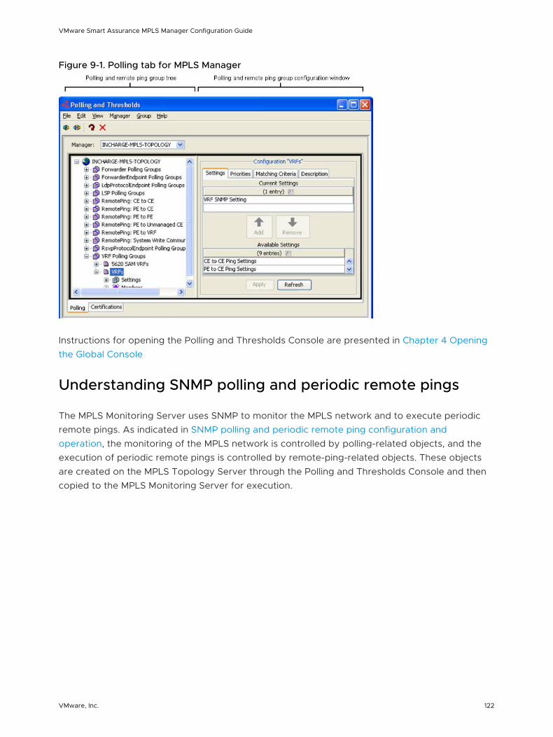
Figure 9-1. Polling tab for MPLS Manager
Instructions for opening the Polling and Thresholds Console are presented in Chapter 4 Opening the Global Console
Understanding SNMP polling and periodic remote pings
The MPLS Monitoring Server uses SNMP to monitor the MPLS network and to execute periodic remote pings. As indicated in SNMP polling and periodic remote ping configuration and operation, the monitoring of the MPLS network is controlled by polling-related objects, and the execution of periodic remote pings is controlled by remote-ping-related objects. These objects are created on the MPLS Topology Server through the Polling and Thresholds Console and then copied to the MPLS Monitoring Server for execution.
VMware Smart Assurance MPLS Manager Configuration Guide
VMware, Inc. 122
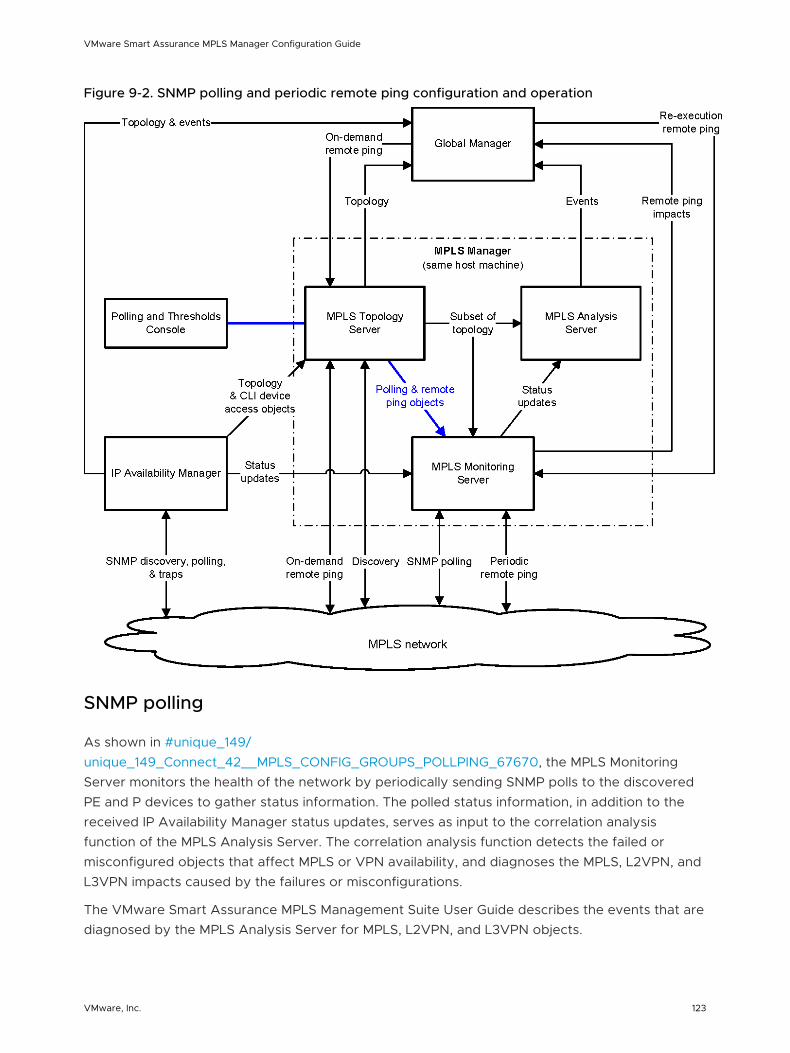
Figure 9-2. SNMP polling and periodic remote ping configuration and operation
SNMP polling
As shown in #unique_149/unique_149_Connect_42__MPLS_CONFIG_GROUPS_POLLPING_67670, the MPLS Monitoring Server monitors the health of the network by periodically sending SNMP polls to the discovered PE and P devices to gather status information. The polled status information, in addition to the received IP Availability Manager status updates, serves as input to the correlation analysis function of the MPLS Analysis Server. The correlation analysis function detects the failed or misconfigured objects that affect MPLS or VPN availability, and diagnoses the MPLS, L2VPN, and L3VPN impacts caused by the failures or misconfigurations.
The VMware Smart Assurance MPLS Management Suite User Guide describes the events that are diagnosed by the MPLS Analysis Server for MPLS, L2VPN, and L3VPN objects.
VMware Smart Assurance MPLS Manager Configuration Guide
VMware, Inc. 123
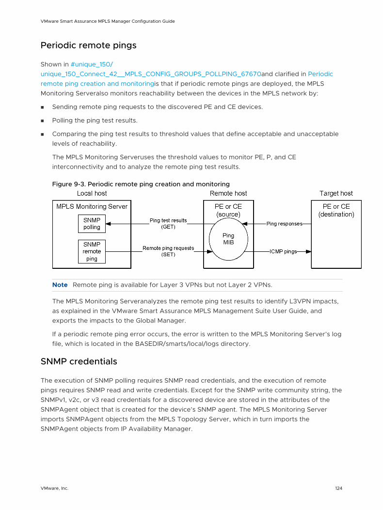
Periodic remote pings
Shown in #unique_150/unique_150_Connect_42__MPLS_CONFIG_GROUPS_POLLPING_67670and clarified in Periodic remote ping creation and monitoringis that if periodic remote pings are deployed, the MPLS Monitoring Serveralso monitors reachability between the devices in the MPLS network by:
n Sending remote ping requests to the discovered PE and CE devices.
n Polling the ping test results.
n Comparing the ping test results to threshold values that define acceptable and unacceptable levels of reachability.
The MPLS Monitoring Serveruses the threshold values to monitor PE, P, and CE interconnectivity and to analyze the remote ping test results.
Figure 9-3. Periodic remote ping creation and monitoring
Note Remote ping is available for Layer 3 VPNs but not Layer 2 VPNs.
The MPLS Monitoring Serveranalyzes the remote ping test results to identify L3VPN impacts, as explained in the VMware Smart Assurance MPLS Management Suite User Guide, and exports the impacts to the Global Manager.
If a periodic remote ping error occurs, the error is written to the MPLS Monitoring Server’s log file, which is located in the BASEDIR/smarts/local/logs directory.
SNMP credentials
The execution of SNMP polling requires SNMP read credentials, and the execution of remote pings requires SNMP read and write credentials. Except for the SNMP write community string, the SNMPv1, v2c, or v3 read credentials for a discovered device are stored in the attributes of the SNMPAgent object that is created for the device’s SNMP agent. The MPLS Monitoring Server imports SNMPAgent objects from the MPLS Topology Server, which in turn imports the SNMPAgent objects from IP Availability Manager.
VMware Smart Assurance MPLS Manager Configuration Guide
VMware, Inc. 124
The SNMPv1 or v2c write community strings for devices are specified in instances of the remote ping group named “System Write Community Strings.” In addition, a default write community string is defined by the WriteCommunity parameter in the REMOTEPING.conf file, as explained in “Description of REMOTEPING.conf” on page 40.
Understanding polling and remote ping groups and settings
Using the Polling and Thresholds Console, you can customize SNMP polling and create periodic remote pings. A periodic remote ping, which is represented as an instance of the VMware Smart Assurance RemotePing class, is configured to run at a user-defined interval for an indefinite period of time.
You customize SNMP polling for the MPLS Monitoring Server by modifying default polling groups or by creating new polling groups. The polling groups periodically poll the managed PE and P devices to collect availability data for LSP, ForwarderEndpoint, LdpProtocolEndpoint, RsvpProtocolEndpoint, and VRF objects. The data serves as input to the correlation analysis function of the MPLS Analysis Server.
Note Chapter 12 SNMP Poller describes SNMP polling for correlation analysis.
You deploy and customize periodic remote pings, and customize the SNMP polling of the remote ping test results, by modifying default remote ping groups or by creating new remote ping groups. The remote ping groups start ping tests on managed PE and CE devices, and periodically poll the devices to collect the ping test results. The ping test results serve as input to the correlation analysis function of the MPLS Monitoring Server.
The VMware Smart Assurance MPLS Management Suite User Guide describes remote ping operation. Chapter 2 Setting Configuration Parameters describes how to enable remote ping and to customize remote ping global values, and Chapter 6 Configuring the Global Manager describes how to enable the use of on-demand (includes re-execution) remote ping server tools.
Modifying polling and remote ping groups
Procedures for modifying existing groups and creating new ones are given in Working with groups and settings.
When you finish editing the properties of a group, you:
1 Click the Applybutton to save the configuration changes to an existing group object or to a newly created group object in the repository of the MPLS Topology Server.
2 Click the Reconfiguretoolbar button
(When the reconfiguration completes, the MPLS Monitoring Serverimports the group object, saves the group object to its repository, and starts the polling or remote ping that is configured for the group object.
VMware Smart Assurance MPLS Manager Configuration Guide
VMware, Inc. 125
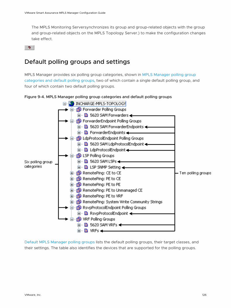
The MPLS Monitoring Serversynchronizes its group and group-related objects with the group and group-related objects on the MPLS Topology Server.) to make the configuration changes take effect.
Default polling groups and settings
MPLS Manager provides six polling group categories, shown in MPLS Manager polling group categories and default polling groups, two of which contain a single default polling group, and four of which contain two default polling groups.
Figure 9-4. MPLS Manager polling group categories and default polling groups
Default MPLS Manager polling groups lists the default polling groups, their target classes, and their settings. The table also identifies the devices that are supported for the polling groups.
VMware Smart Assurance MPLS Manager Configuration Guide
VMware, Inc. 126
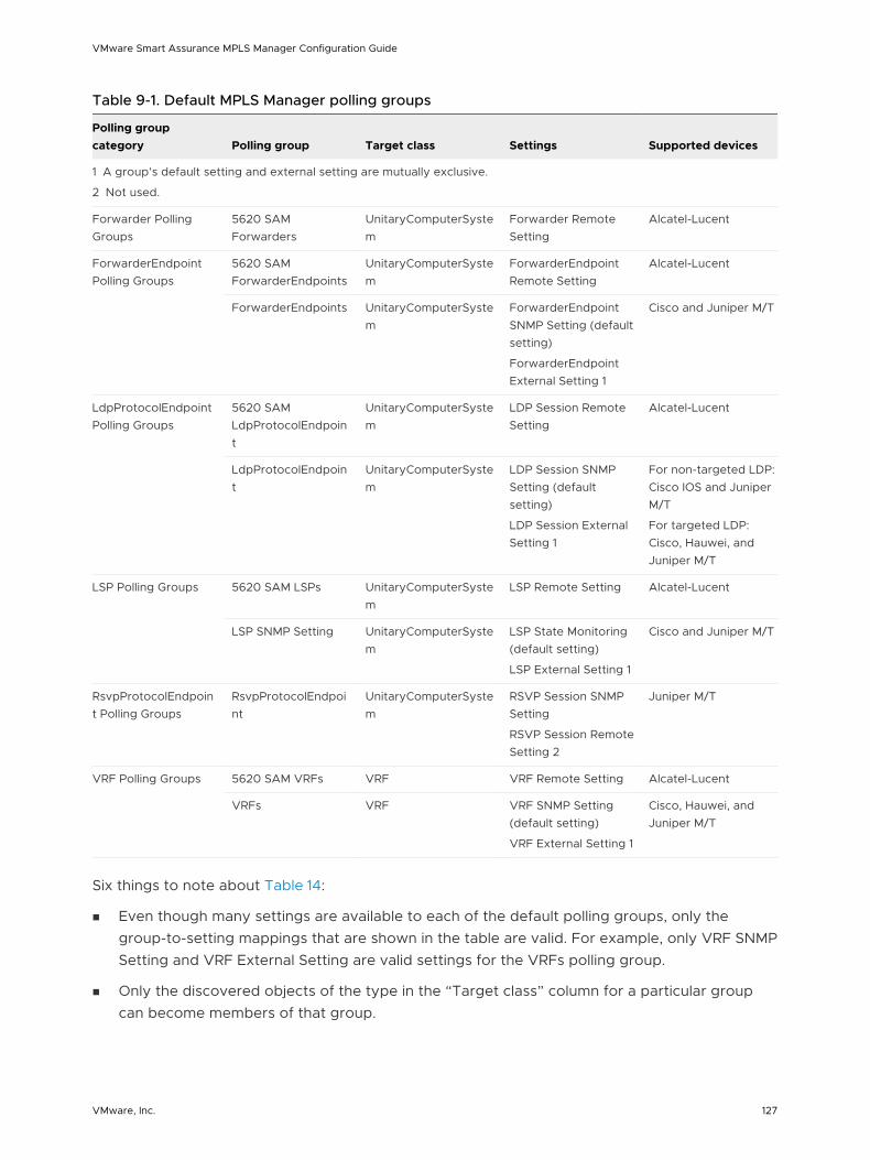
Table 9-1. Default MPLS Manager polling groups
Polling group category Polling group Target class Settings Supported devices
1 A group’s default setting and external setting are mutually exclusive.
2 Not used.
Forwarder Polling Groups
5620 SAM Forwarders
UnitaryComputerSystem
Forwarder Remote Setting
Alcatel-Lucent
ForwarderEndpoint Polling Groups
5620 SAM ForwarderEndpoints
UnitaryComputerSystem
ForwarderEndpoint Remote Setting
Alcatel-Lucent
ForwarderEndpoints UnitaryComputerSystem
ForwarderEndpoint SNMP Setting (default setting)
ForwarderEndpoint External Setting 1
Cisco and Juniper M/T
LdpProtocolEndpoint Polling Groups
5620 SAM LdpProtocolEndpoint
UnitaryComputerSystem
LDP Session Remote Setting
Alcatel-Lucent
LdpProtocolEndpoint
UnitaryComputerSystem
LDP Session SNMP Setting (default setting)
LDP Session External Setting 1
For non-targeted LDP: Cisco IOS and Juniper M/T
For targeted LDP: Cisco, Hauwei, and Juniper M/T
LSP Polling Groups 5620 SAM LSPs UnitaryComputerSystem
LSP Remote Setting Alcatel-Lucent
LSP SNMP Setting UnitaryComputerSystem
LSP State Monitoring (default setting)
LSP External Setting 1
Cisco and Juniper M/T
RsvpProtocolEndpoint Polling Groups
RsvpProtocolEndpoint
UnitaryComputerSystem
RSVP Session SNMP Setting
RSVP Session Remote Setting 2
Juniper M/T
VRF Polling Groups 5620 SAM VRFs VRF VRF Remote Setting Alcatel-Lucent
VRFs VRF VRF SNMP Setting (default setting)
VRF External Setting 1
Cisco, Hauwei, and Juniper M/T
Six things to note about Table 14:
n Even though many settings are available to each of the default polling groups, only the group-to-setting mappings that are shown in the table are valid. For example, only VRF SNMP Setting and VRF External Setting are valid settings for the VRFs polling group.
n Only the discovered objects of the type in the “Target class” column for a particular group can become members of that group.
VMware Smart Assurance MPLS Manager Configuration Guide
VMware, Inc. 127

n By default, all discovered objects of the type in the “Target class” column for a particular group become members of that group.
You can specify matching criteria for a polling group to limit its membership, as explained in Edit matching criteria.
n The following five polling groups are specific to the VMware Smart Assurance Adapter for Alcatel-Lucent 5620 SAM EMS (the Adapter):
n 5620 SAM Forwarders
n 5620 SAM ForwarderEndpoints
n 5620 SAM LdpProtocolEndpoint
n 5620 SAM LSPs
n 5620 SAM VRFs
n The 5620 SAM polling groups always appear, regardless of whether an Adapter license is available, but the groups are active only if an Adapter license is available.
The 5620 SAM polling groups are described in the VMware Smart Assurance Adapter for Alcatel-Lucent 5620 SAM EMS User Guide.
n The following five polling groups are described in this section:
n ForwarderEndpoints
n LdpProtocolEndpoint
n LSP SNMP Setting
n RsvpProtocolEndpoint
n VRFs
ForwarderEndpoints polling group
The ForwarderEndpoints default polling group is used by MPLS Manager to monitor the availability of Forwarder endpoint connections. MPLS Manager monitors the availability by monitoring the ForwarderEndpoints that are discovered on PE devices.
The ForwarderEndpoints polling group has a default setting and an optional setting:
n ForwarderEndpoint SNMP Setting (default)
n ForwarderEndpoint External Setting (optional)
The two settings are mutually exclusive, meaning that only one or the other (but not both) can be specified for a ForwarderEndpoints polling group at any given time.
ForwarderEndpoint SNMP Setting
VMware Smart Assurance MPLS Manager Configuration Guide
VMware, Inc. 128
The ForwarderEndpoint SNMP Setting determines the polling intervals that are used by MPLS Manager to monitor ForwarderEndpoints. MPLS Manager monitors the endpoints by probing the SNMP tables on the PE devices.
ForwarderEndpoint SNMP Setting parameters and their values lists the ForwarderEndpoint SNMP Setting parameters.
Table 9-2. ForwarderEndpoint SNMP Setting parameters and their values
Parameter Values Description
AnalysisMode ENABLED,DISABLED
Default: ENABLED
Enables or disables:
1 The MPLS Manager polling of Forwarder endpoint (ForwarderEndpoint) data.
2 The subsequent analysis of the polled data to determine the status of Forwarder endpoint connections.
PollingInterval 30 to 3600 seconds
Default: 240 seconds
Sets the time between successive polls.
Retries 0 to 10 retries
Default: 3
Sets the number of retry polls to perform when the initial poll fails.
Timeout 10 to 10000 milliseconds
Default: 700 milliseconds
Sets the amount of time to wait for the poll response before the first poll request times out. The timeout value doubles for each successive retry.
For Timeout=700 msec (0.7 sec) and Retries=3:
n 0.7 seconds for first retry
n 1.4 seconds for second retry
n 2.8 seconds for third retry
ForwarderEndpoint External Setting
The ForwarderEndpoint External Setting serves two purposes:
n Provides a means of testing the Forwarder endpoint instrumentation and analysis functionality of MPLS Manager.
n Provides a means for MPLS Manager to import Forwarder endpoint status updates from an VMware Smart Assurance adapter, such as the VMware Smart Assurance Adapter for Alcatel-Lucent 5620 SAM EMS.
ForwarderEndpoint External Setting parameters and their values lists the ForwarderEndpoint External Setting parameters.
VMware Smart Assurance MPLS Manager Configuration Guide
VMware, Inc. 129
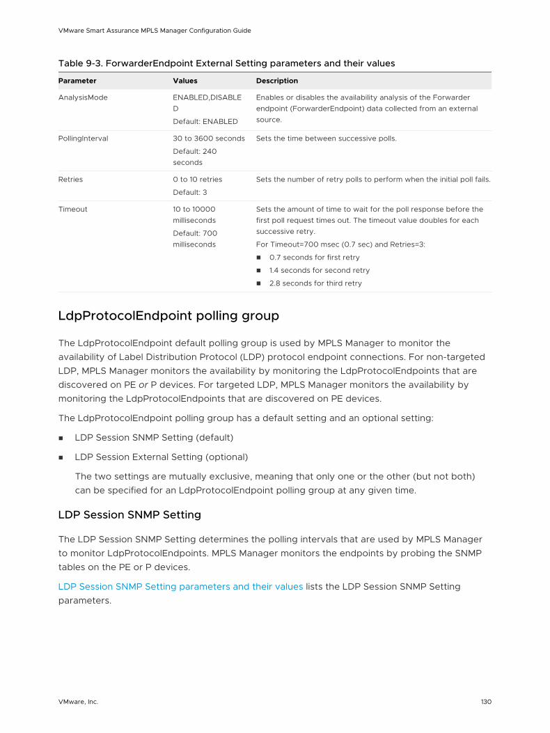
Table 9-3. ForwarderEndpoint External Setting parameters and their values
Parameter Values Description
AnalysisMode ENABLED,DISABLED
Default: ENABLED
Enables or disables the availability analysis of the Forwarder endpoint (ForwarderEndpoint) data collected from an external source.
PollingInterval 30 to 3600 seconds
Default: 240 seconds
Sets the time between successive polls.
Retries 0 to 10 retries
Default: 3
Sets the number of retry polls to perform when the initial poll fails.
Timeout 10 to 10000 milliseconds
Default: 700 milliseconds
Sets the amount of time to wait for the poll response before the first poll request times out. The timeout value doubles for each successive retry.
For Timeout=700 msec (0.7 sec) and Retries=3:
n 0.7 seconds for first retry
n 1.4 seconds for second retry
n 2.8 seconds for third retry
LdpProtocolEndpoint polling group
The LdpProtocolEndpoint default polling group is used by MPLS Manager to monitor the availability of Label Distribution Protocol (LDP) protocol endpoint connections. For non-targeted LDP, MPLS Manager monitors the availability by monitoring the LdpProtocolEndpoints that are discovered on PE or P devices. For targeted LDP, MPLS Manager monitors the availability by monitoring the LdpProtocolEndpoints that are discovered on PE devices.
The LdpProtocolEndpoint polling group has a default setting and an optional setting:
n LDP Session SNMP Setting (default)
n LDP Session External Setting (optional)
The two settings are mutually exclusive, meaning that only one or the other (but not both) can be specified for an LdpProtocolEndpoint polling group at any given time.
LDP Session SNMP Setting
The LDP Session SNMP Setting determines the polling intervals that are used by MPLS Manager to monitor LdpProtocolEndpoints. MPLS Manager monitors the endpoints by probing the SNMP tables on the PE or P devices.
LDP Session SNMP Setting parameters and their values lists the LDP Session SNMP Setting parameters.
VMware Smart Assurance MPLS Manager Configuration Guide
VMware, Inc. 130
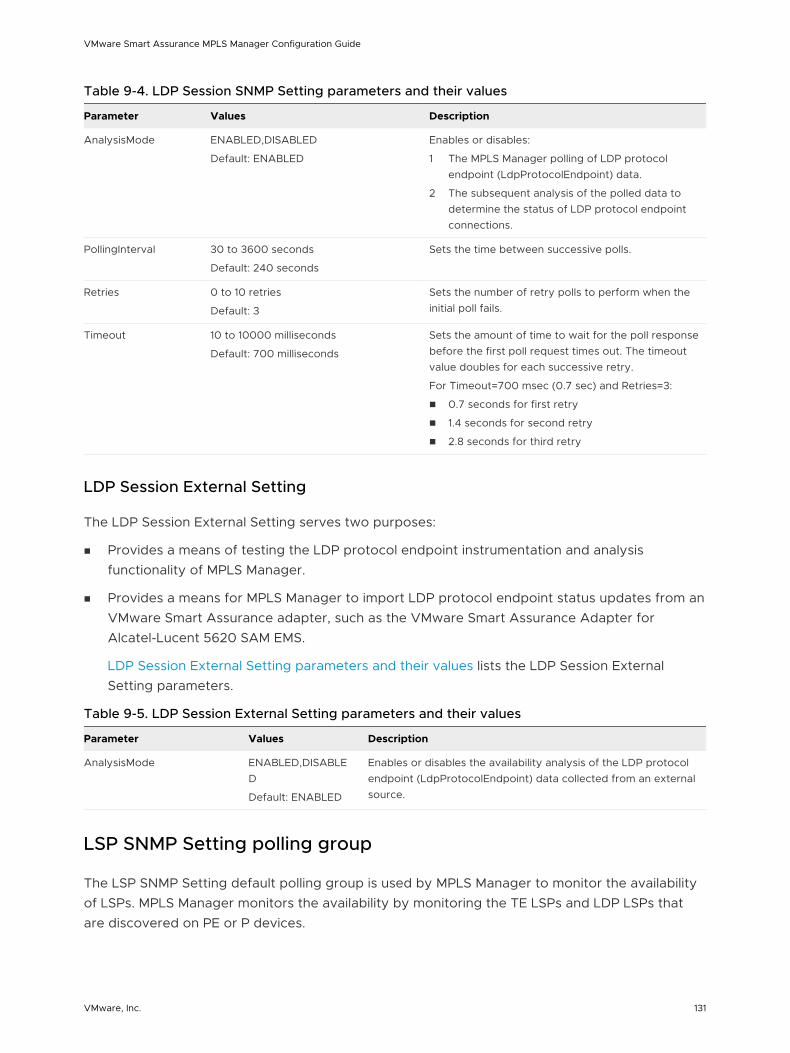
Table 9-4. LDP Session SNMP Setting parameters and their values
Parameter Values Description
AnalysisMode ENABLED,DISABLED
Default: ENABLED
Enables or disables:
1 The MPLS Manager polling of LDP protocol endpoint (LdpProtocolEndpoint) data.
2 The subsequent analysis of the polled data to determine the status of LDP protocol endpoint connections.
PollingInterval 30 to 3600 seconds
Default: 240 seconds
Sets the time between successive polls.
Retries 0 to 10 retries
Default: 3
Sets the number of retry polls to perform when the initial poll fails.
Timeout 10 to 10000 milliseconds
Default: 700 milliseconds
Sets the amount of time to wait for the poll response before the first poll request times out. The timeout value doubles for each successive retry.
For Timeout=700 msec (0.7 sec) and Retries=3:
n 0.7 seconds for first retry
n 1.4 seconds for second retry
n 2.8 seconds for third retry
LDP Session External Setting
The LDP Session External Setting serves two purposes:
n Provides a means of testing the LDP protocol endpoint instrumentation and analysis functionality of MPLS Manager.
n Provides a means for MPLS Manager to import LDP protocol endpoint status updates from an VMware Smart Assurance adapter, such as the VMware Smart Assurance Adapter for Alcatel-Lucent 5620 SAM EMS.
LDP Session External Setting parameters and their values lists the LDP Session External Setting parameters.
Table 9-5. LDP Session External Setting parameters and their values
Parameter Values Description
AnalysisMode ENABLED,DISABLED
Default: ENABLED
Enables or disables the availability analysis of the LDP protocol endpoint (LdpProtocolEndpoint) data collected from an external source.
LSP SNMP Setting polling group
The LSP SNMP Setting default polling group is used by MPLS Manager to monitor the availability of LSPs. MPLS Manager monitors the availability by monitoring the TE LSPs and LDP LSPs that are discovered on PE or P devices.
VMware Smart Assurance MPLS Manager Configuration Guide
VMware, Inc. 131
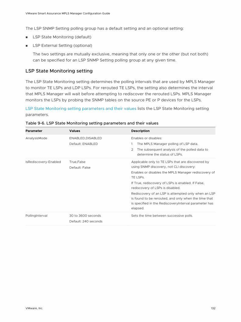
The LSP SNMP Setting polling group has a default setting and an optional setting:
n LSP State Monitoring (default)
n LSP External Setting (optional)
The two settings are mutually exclusive, meaning that only one or the other (but not both) can be specified for an LSP SNMP Setting polling group at any given time.
LSP State Monitoring setting
The LSP State Monitoring setting determines the polling intervals that are used by MPLS Manager to monitor TE LSPs and LDP LSPs. For rerouted TE LSPs, the setting also determines the interval that MPLS Manager will wait before attempting to rediscover the rerouted LSPs. MPLS Manager monitors the LSPs by probing the SNMP tables on the source PE or P devices for the LSPs.
LSP State Monitoring setting parameters and their values lists the LSP State Monitoring setting parameters.
Table 9-6. LSP State Monitoring setting parameters and their values
Parameter Values Description
AnalysisMode ENABLED,DISABLED
Default: ENABLED
Enables or disables:
1 The MPLS Manager polling of LSP data.
2 The subsequent analysis of the polled data to determine the status of LSPs.
IsRediscovery-Enabled True,False
Default: False
Applicable only to TE LSPs that are discovered by using SNMP discovery, not CLI discovery:
Enables or disables the MPLS Manager rediscovery of TE LSPs.
If True, rediscovery of LSPs is enabled. If False, rediscovery of LSPs is disabled.
Rediscovery of an LSP is attempted only when an LSP is found to be rerouted, and only when the time that is specified in the RediscoveryInterval parameter has elapsed.
PollingInterval 30 to 3600 seconds
Default: 240 seconds
Sets the time between successive polls.
VMware Smart Assurance MPLS Manager Configuration Guide
VMware, Inc. 132
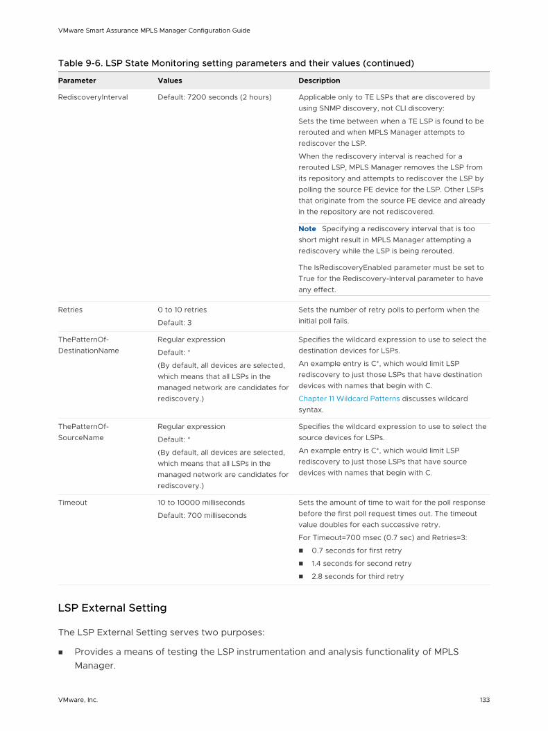
Table 9-6. LSP State Monitoring setting parameters and their values (continued)
Parameter Values Description
RediscoveryInterval Default: 7200 seconds (2 hours) Applicable only to TE LSPs that are discovered by using SNMP discovery, not CLI discovery:
Sets the time between when a TE LSP is found to be rerouted and when MPLS Manager attempts to rediscover the LSP.
When the rediscovery interval is reached for a rerouted LSP, MPLS Manager removes the LSP from its repository and attempts to rediscover the LSP by polling the source PE device for the LSP. Other LSPs that originate from the source PE device and already in the repository are not rediscovered.
Note Specifying a rediscovery interval that is too short might result in MPLS Manager attempting a rediscovery while the LSP is being rerouted.
The IsRediscoveryEnabled parameter must be set to True for the Rediscovery-Interval parameter to have any effect.
Retries 0 to 10 retries
Default: 3
Sets the number of retry polls to perform when the initial poll fails.
ThePatternOf-DestinationName
Regular expression
Default: *
(By default, all devices are selected, which means that all LSPs in the managed network are candidates for rediscovery.)
Specifies the wildcard expression to use to select the destination devices for LSPs.
An example entry is C*, which would limit LSP rediscovery to just those LSPs that have destination devices with names that begin with C.
Chapter 11 Wildcard Patterns discusses wildcard syntax.
ThePatternOf-SourceName
Regular expression
Default: *
(By default, all devices are selected, which means that all LSPs in the managed network are candidates for rediscovery.)
Specifies the wildcard expression to use to select the source devices for LSPs.
An example entry is C*, which would limit LSP rediscovery to just those LSPs that have source devices with names that begin with C.
Timeout 10 to 10000 milliseconds
Default: 700 milliseconds
Sets the amount of time to wait for the poll response before the first poll request times out. The timeout value doubles for each successive retry.
For Timeout=700 msec (0.7 sec) and Retries=3:
n 0.7 seconds for first retry
n 1.4 seconds for second retry
n 2.8 seconds for third retry
LSP External Setting
The LSP External Setting serves two purposes:
n Provides a means of testing the LSP instrumentation and analysis functionality of MPLS Manager.
VMware Smart Assurance MPLS Manager Configuration Guide
VMware, Inc. 133
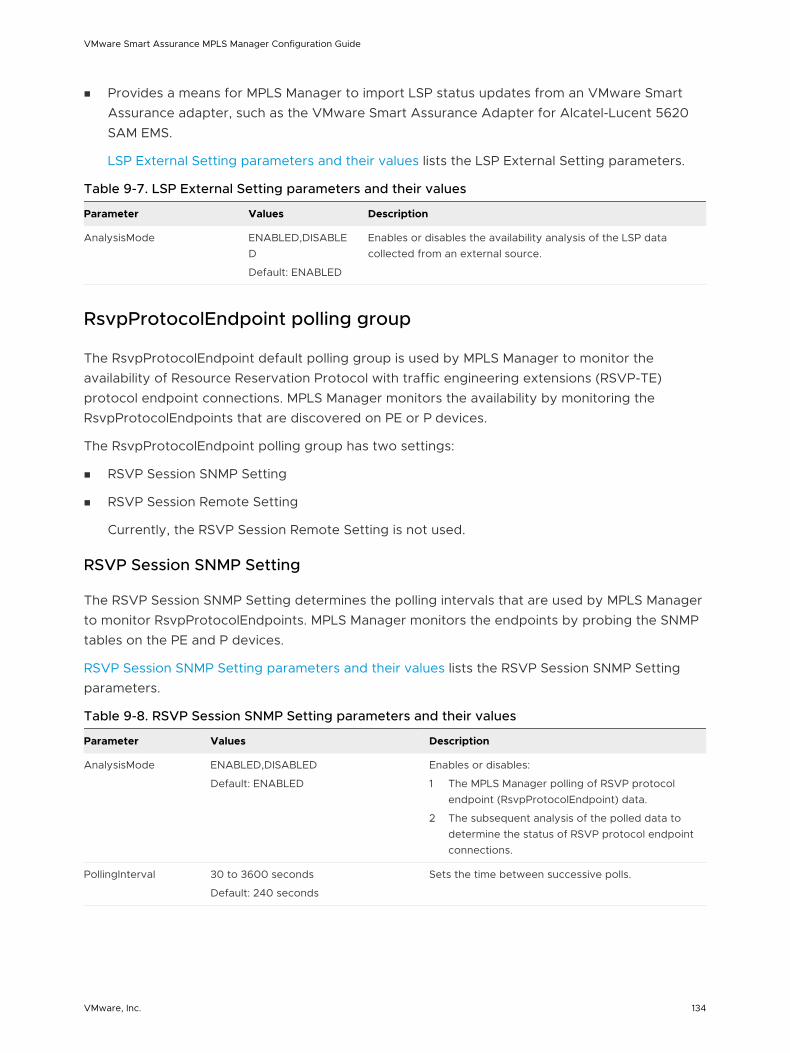
n Provides a means for MPLS Manager to import LSP status updates from an VMware Smart Assurance adapter, such as the VMware Smart Assurance Adapter for Alcatel-Lucent 5620 SAM EMS.
LSP External Setting parameters and their values lists the LSP External Setting parameters.
Table 9-7. LSP External Setting parameters and their values
Parameter Values Description
AnalysisMode ENABLED,DISABLED
Default: ENABLED
Enables or disables the availability analysis of the LSP data collected from an external source.
RsvpProtocolEndpoint polling group
The RsvpProtocolEndpoint default polling group is used by MPLS Manager to monitor the availability of Resource Reservation Protocol with traffic engineering extensions (RSVP-TE) protocol endpoint connections. MPLS Manager monitors the availability by monitoring the RsvpProtocolEndpoints that are discovered on PE or P devices.
The RsvpProtocolEndpoint polling group has two settings:
n RSVP Session SNMP Setting
n RSVP Session Remote Setting
Currently, the RSVP Session Remote Setting is not used.
RSVP Session SNMP Setting
The RSVP Session SNMP Setting determines the polling intervals that are used by MPLS Manager to monitor RsvpProtocolEndpoints. MPLS Manager monitors the endpoints by probing the SNMP tables on the PE and P devices.
RSVP Session SNMP Setting parameters and their values lists the RSVP Session SNMP Setting parameters.
Table 9-8. RSVP Session SNMP Setting parameters and their values
Parameter Values Description
AnalysisMode ENABLED,DISABLED
Default: ENABLED
Enables or disables:
1 The MPLS Manager polling of RSVP protocol endpoint (RsvpProtocolEndpoint) data.
2 The subsequent analysis of the polled data to determine the status of RSVP protocol endpoint connections.
PollingInterval 30 to 3600 seconds
Default: 240 seconds
Sets the time between successive polls.
VMware Smart Assurance MPLS Manager Configuration Guide
VMware, Inc. 134
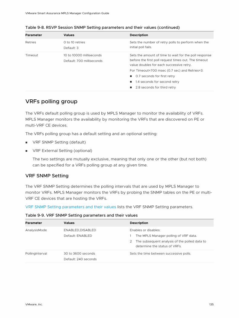
Table 9-8. RSVP Session SNMP Setting parameters and their values (continued)
Parameter Values Description
Retries 0 to 10 retries
Default: 3
Sets the number of retry polls to perform when the initial poll fails.
Timeout 10 to 10000 milliseconds
Default: 700 milliseconds
Sets the amount of time to wait for the poll response before the first poll request times out. The timeout value doubles for each successive retry.
For Timeout=700 msec (0.7 sec) and Retries=3:
n 0.7 seconds for first retry
n 1.4 seconds for second retry
n 2.8 seconds for third retry
VRFs polling group
The VRFs default polling group is used by MPLS Manager to monitor the availability of VRFs. MPLS Manager monitors the availability by monitoring the VRFs that are discovered on PE or multi-VRF CE devices.
The VRFs polling group has a default setting and an optional setting:
n VRF SNMP Setting (default)
n VRF External Setting (optional)
The two settings are mutually exclusive, meaning that only one or the other (but not both) can be specified for a VRFs polling group at any given time.
VRF SNMP Setting
The VRF SNMP Setting determines the polling intervals that are used by MPLS Manager to monitor VRFs. MPLS Manager monitors the VRFs by probing the SNMP tables on the PE or multi-VRF CE devices that are hosting the VRFs.
VRF SNMP Setting parameters and their values lists the VRF SNMP Setting parameters.
Table 9-9. VRF SNMP Setting parameters and their values
Parameter Values Description
AnalysisMode ENABLED,DISABLED
Default: ENABLED
Enables or disables:
1 The MPLS Manager polling of VRF data.
2 The subsequent analysis of the polled data to determine the status of VRFs.
PollingInterval 30 to 3600 seconds
Default: 240 seconds
Sets the time between successive polls.
VMware Smart Assurance MPLS Manager Configuration Guide
VMware, Inc. 135
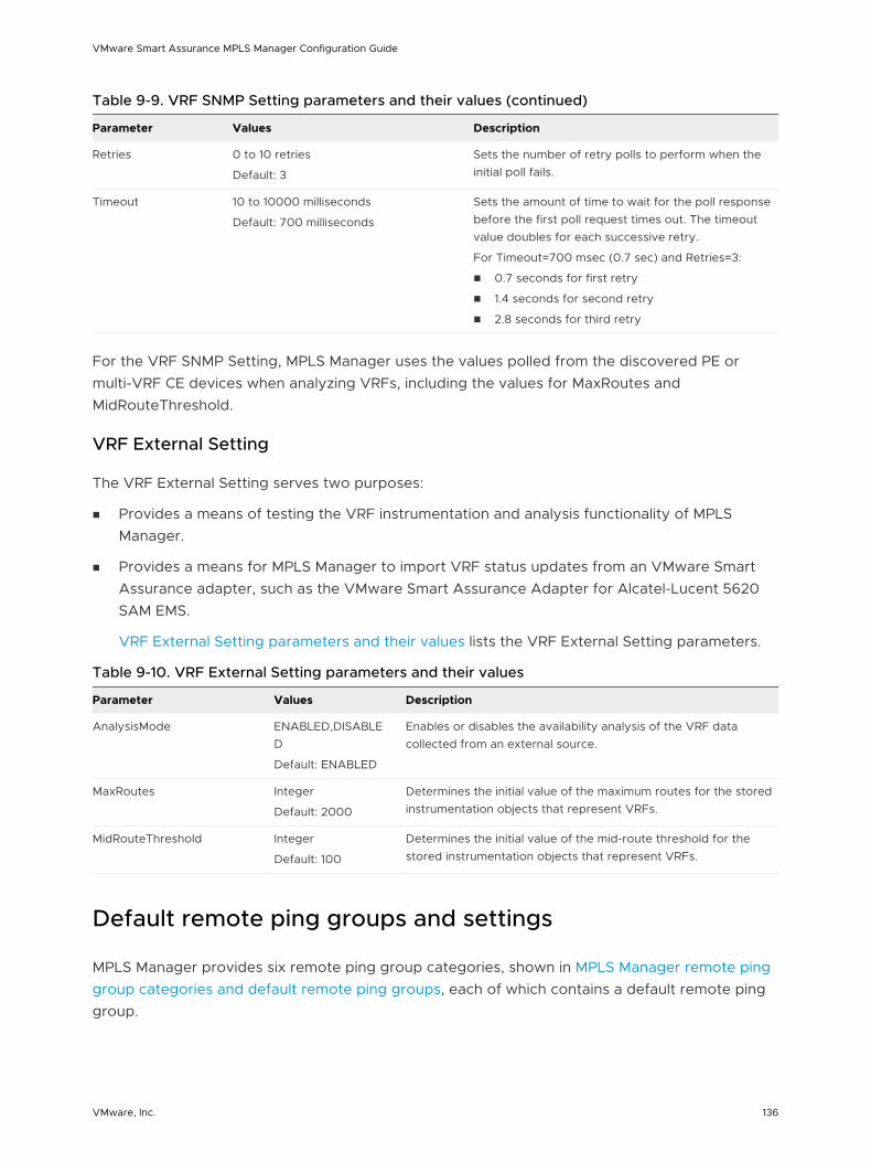
Table 9-9. VRF SNMP Setting parameters and their values (continued)
Parameter Values Description
Retries 0 to 10 retries
Default: 3
Sets the number of retry polls to perform when the initial poll fails.
Timeout 10 to 10000 milliseconds
Default: 700 milliseconds
Sets the amount of time to wait for the poll response before the first poll request times out. The timeout value doubles for each successive retry.
For Timeout=700 msec (0.7 sec) and Retries=3:
n 0.7 seconds for first retry
n 1.4 seconds for second retry
n 2.8 seconds for third retry
For the VRF SNMP Setting, MPLS Manager uses the values polled from the discovered PE or multi-VRF CE devices when analyzing VRFs, including the values for MaxRoutes and MidRouteThreshold.
VRF External Setting
The VRF External Setting serves two purposes:
n Provides a means of testing the VRF instrumentation and analysis functionality of MPLS Manager.
n Provides a means for MPLS Manager to import VRF status updates from an VMware Smart Assurance adapter, such as the VMware Smart Assurance Adapter for Alcatel-Lucent 5620 SAM EMS.
VRF External Setting parameters and their values lists the VRF External Setting parameters.
Table 9-10. VRF External Setting parameters and their values
Parameter Values Description
AnalysisMode ENABLED,DISABLED
Default: ENABLED
Enables or disables the availability analysis of the VRF data collected from an external source.
MaxRoutes Integer
Default: 2000
Determines the initial value of the maximum routes for the stored instrumentation objects that represent VRFs.
MidRouteThreshold Integer
Default: 100
Determines the initial value of the mid-route threshold for the stored instrumentation objects that represent VRFs.
Default remote ping groups and settings
MPLS Manager provides six remote ping group categories, shown in MPLS Manager remote ping group categories and default remote ping groups, each of which contains a default remote ping group.
VMware Smart Assurance MPLS Manager Configuration Guide
VMware, Inc. 136
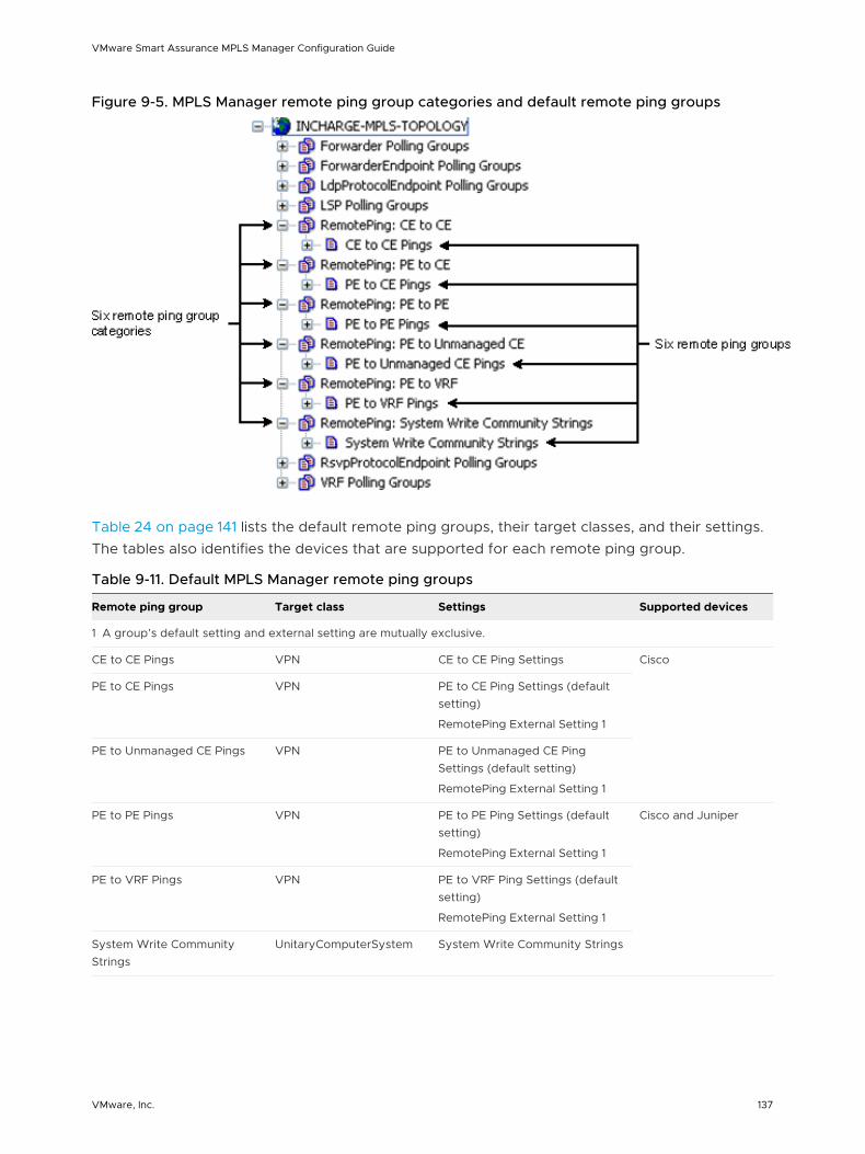
Figure 9-5. MPLS Manager remote ping group categories and default remote ping groups
Table 24 on page 141 lists the default remote ping groups, their target classes, and their settings. The tables also identifies the devices that are supported for each remote ping group.
Table 9-11. Default MPLS Manager remote ping groups
Remote ping group Target class Settings Supported devices
1 A group’s default setting and external setting are mutually exclusive.
CE to CE Pings VPN CE to CE Ping Settings Cisco
PE to CE Pings VPN PE to CE Ping Settings (default setting)
RemotePing External Setting 1
PE to Unmanaged CE Pings VPN PE to Unmanaged CE Ping Settings (default setting)
RemotePing External Setting 1
PE to PE Pings VPN PE to PE Ping Settings (default setting)
RemotePing External Setting 1
Cisco and Juniper
PE to VRF Pings VPN PE to VRF Ping Settings (default setting)
RemotePing External Setting 1
System Write Community Strings
UnitaryComputerSystem System Write Community Strings
VMware Smart Assurance MPLS Manager Configuration Guide
VMware, Inc. 137
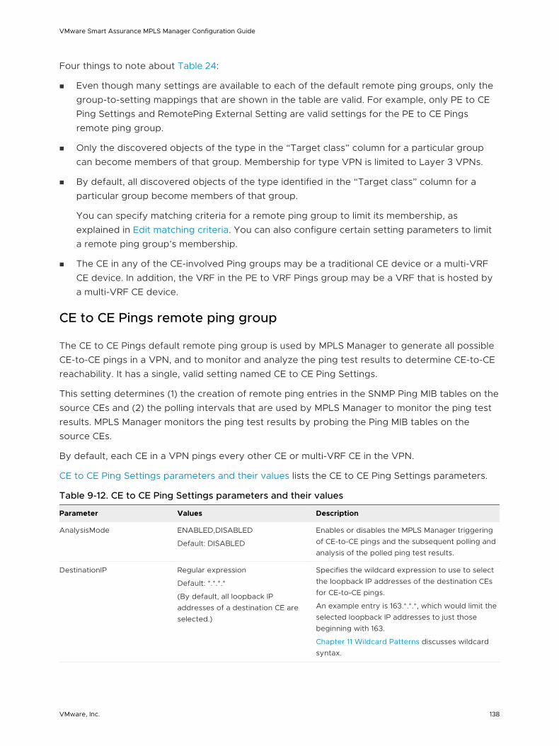
Four things to note about Table 24:
n Even though many settings are available to each of the default remote ping groups, only the group-to-setting mappings that are shown in the table are valid. For example, only PE to CE Ping Settings and RemotePing External Setting are valid settings for the PE to CE Pings remote ping group.
n Only the discovered objects of the type in the “Target class” column for a particular group can become members of that group. Membership for type VPN is limited to Layer 3 VPNs.
n By default, all discovered objects of the type identified in the “Target class” column for a particular group become members of that group.
You can specify matching criteria for a remote ping group to limit its membership, as explained in Edit matching criteria. You can also configure certain setting parameters to limit a remote ping group’s membership.
n The CE in any of the CE-involved Ping groups may be a traditional CE device or a multi-VRF CE device. In addition, the VRF in the PE to VRF Pings group may be a VRF that is hosted by a multi-VRF CE device.
CE to CE Pings remote ping group
The CE to CE Pings default remote ping group is used by MPLS Manager to generate all possible CE-to-CE pings in a VPN, and to monitor and analyze the ping test results to determine CE-to-CE reachability. It has a single, valid setting named CE to CE Ping Settings.
This setting determines (1) the creation of remote ping entries in the SNMP Ping MIB tables on the source CEs and (2) the polling intervals that are used by MPLS Manager to monitor the ping test results. MPLS Manager monitors the ping test results by probing the Ping MIB tables on the source CEs.
By default, each CE in a VPN pings every other CE or multi-VRF CE in the VPN.
CE to CE Ping Settings parameters and their values lists the CE to CE Ping Settings parameters.
Table 9-12. CE to CE Ping Settings parameters and their values
Parameter Values Description
AnalysisMode ENABLED,DISABLED
Default: DISABLED
Enables or disables the MPLS Manager triggering of CE-to-CE pings and the subsequent polling and analysis of the polled ping test results.
DestinationIP Regular expression
Default: *.*.*.*
(By default, all loopback IP addresses of a destination CE are selected.)
Specifies the wildcard expression to use to select the loopback IP addresses of the destination CEs for CE-to-CE pings.
An example entry is 163.*.*.*, which would limit the selected loopback IP addresses to just those beginning with 163.
Chapter 11 Wildcard Patterns discusses wildcard syntax.
VMware Smart Assurance MPLS Manager Configuration Guide
VMware, Inc. 138
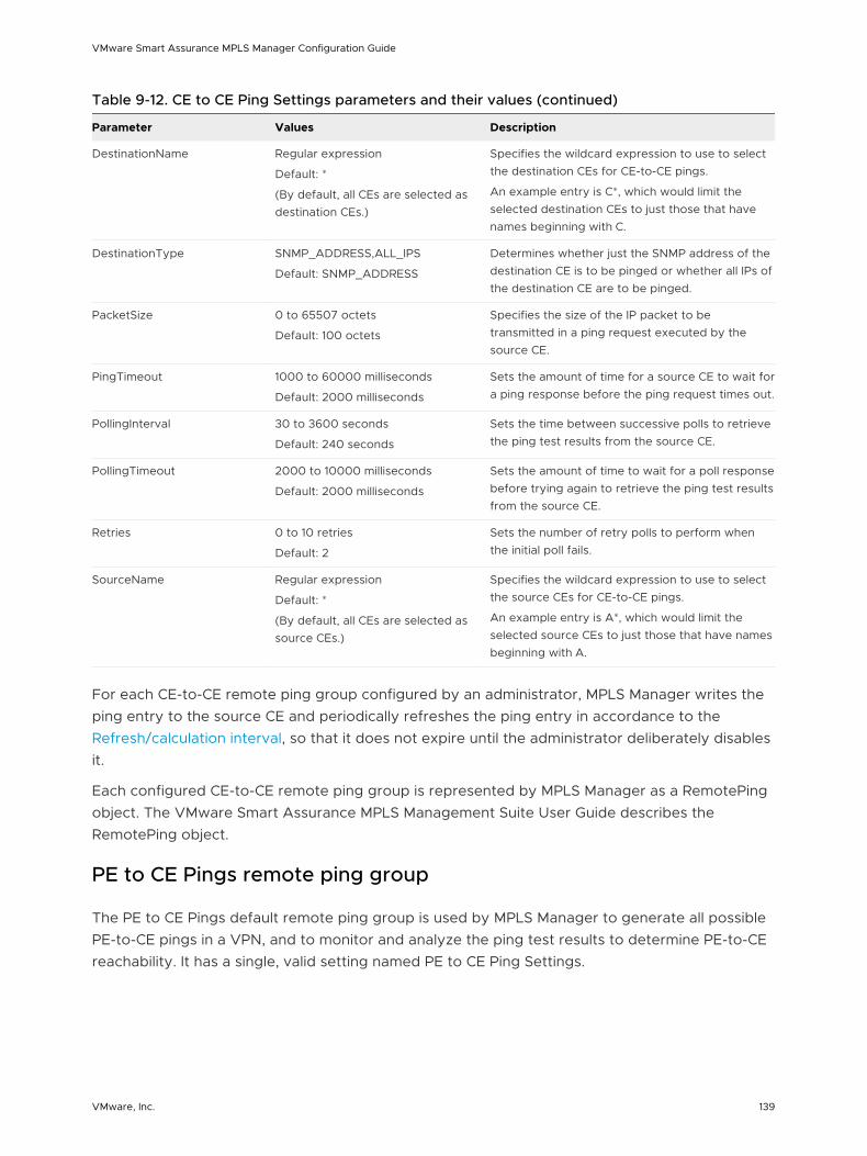
Table 9-12. CE to CE Ping Settings parameters and their values (continued)
Parameter Values Description
DestinationName Regular expression
Default: *
(By default, all CEs are selected as destination CEs.)
Specifies the wildcard expression to use to select the destination CEs for CE-to-CE pings.
An example entry is C*, which would limit the selected destination CEs to just those that have names beginning with C.
DestinationType SNMP_ADDRESS,ALL_IPS
Default: SNMP_ADDRESS
Determines whether just the SNMP address of the destination CE is to be pinged or whether all IPs of the destination CE are to be pinged.
PacketSize 0 to 65507 octets
Default: 100 octets
Specifies the size of the IP packet to be transmitted in a ping request executed by the source CE.
PingTimeout 1000 to 60000 milliseconds
Default: 2000 milliseconds
Sets the amount of time for a source CE to wait for a ping response before the ping request times out.
PollingInterval 30 to 3600 seconds
Default: 240 seconds
Sets the time between successive polls to retrieve the ping test results from the source CE.
PollingTimeout 2000 to 10000 milliseconds
Default: 2000 milliseconds
Sets the amount of time to wait for a poll response before trying again to retrieve the ping test results from the source CE.
Retries 0 to 10 retries
Default: 2
Sets the number of retry polls to perform when the initial poll fails.
SourceName Regular expression
Default: *
(By default, all CEs are selected as source CEs.)
Specifies the wildcard expression to use to select the source CEs for CE-to-CE pings.
An example entry is A*, which would limit the selected source CEs to just those that have names beginning with A.
For each CE-to-CE remote ping group configured by an administrator, MPLS Manager writes the ping entry to the source CE and periodically refreshes the ping entry in accordance to the Refresh/calculation interval, so that it does not expire until the administrator deliberately disables it.
Each configured CE-to-CE remote ping group is represented by MPLS Manager as a RemotePing object. The VMware Smart Assurance MPLS Management Suite User Guide describes the RemotePing object.
PE to CE Pings remote ping group
The PE to CE Pings default remote ping group is used by MPLS Manager to generate all possible PE-to-CE pings in a VPN, and to monitor and analyze the ping test results to determine PE-to-CE reachability. It has a single, valid setting named PE to CE Ping Settings.
VMware Smart Assurance MPLS Manager Configuration Guide
VMware, Inc. 139
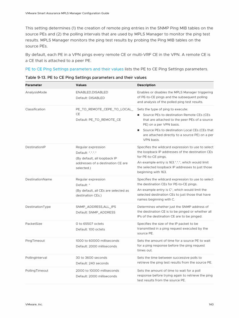
This setting determines (1) the creation of remote ping entries in the SNMP Ping MIB tables on the source PEs and (2) the polling intervals that are used by MPLS Manager to monitor the ping test results. MPLS Manager monitors the ping test results by probing the Ping MIB tables on the source PEs.
By default, each PE in a VPN pings every remote CE or multi-VRF CE in the VPN. A remote CE is a CE that is attached to a peer PE.
PE to CE Ping Settings parameters and their values lists the PE to CE Ping Settings parameters.
Table 9-13. PE to CE Ping Settings parameters and their values
Parameter Values Description
AnalysisMode ENABLED,DISABLED
Default: DISABLED
Enables or disables the MPLS Manager triggering of PE-to-CE pings and the subsequent polling and analysis of the polled ping test results.
Classification PE_TO_REMOTE_CEPE_TO_LOCAL_CE
Default: PE_TO_REMOTE_CE
Sets the type of ping to execute:
n Source PEs to destination Remote CEs (CEs that are attached to the peer PEs of a source PE) on a per VPN basis.
n Source PEs to destination Local CEs (CEs that are attached directly to a source PE) on a per VPN basis.
DestinationIP Regular expression
Default: *.*.*.*
(By default, all loopback IP addresses of a destination CE are selected.)
Specifies the wildcard expression to use to select the loopback IP addresses of the destination CEs for PE-to-CE pings.
An example entry is 163.*.*.*, which would limit the selected loopback IP addresses to just those beginning with 163.
DestinationName Regular expression
Default: *
(By default, all CEs are selected as destination CEs.)
Specifies the wildcard expression to use to select the destination CEs for PE-to-CE pings.
An example entry is C*, which would limit the selected destination CEs to just those that have names beginning with C.
DestinationType SNMP_ADDRESS,ALL_IPS
Default: SNMP_ADDRESS
Determines whether just the SNMP address of the destination CE is to be pinged or whether all IPs of the destination CE are to be pinged.
PacketSize 0 to 65507 octets
Default: 100 octets
Specifies the size of the IP packet to be transmitted in a ping request executed by the source PE.
PingTimeout 1000 to 60000 milliseconds
Default: 2000 milliseconds
Sets the amount of time for a source PE to wait for a ping response before the ping request times out.
PollingInterval 30 to 3600 seconds
Default: 240 seconds
Sets the time between successive polls to retrieve the ping test results from the source PE.
PollingTimeout 2000 to 10000 milliseconds
Default: 2000 milliseconds
Sets the amount of time to wait for a poll response before trying again to retrieve the ping test results from the source PE.
VMware Smart Assurance MPLS Manager Configuration Guide
VMware, Inc. 140
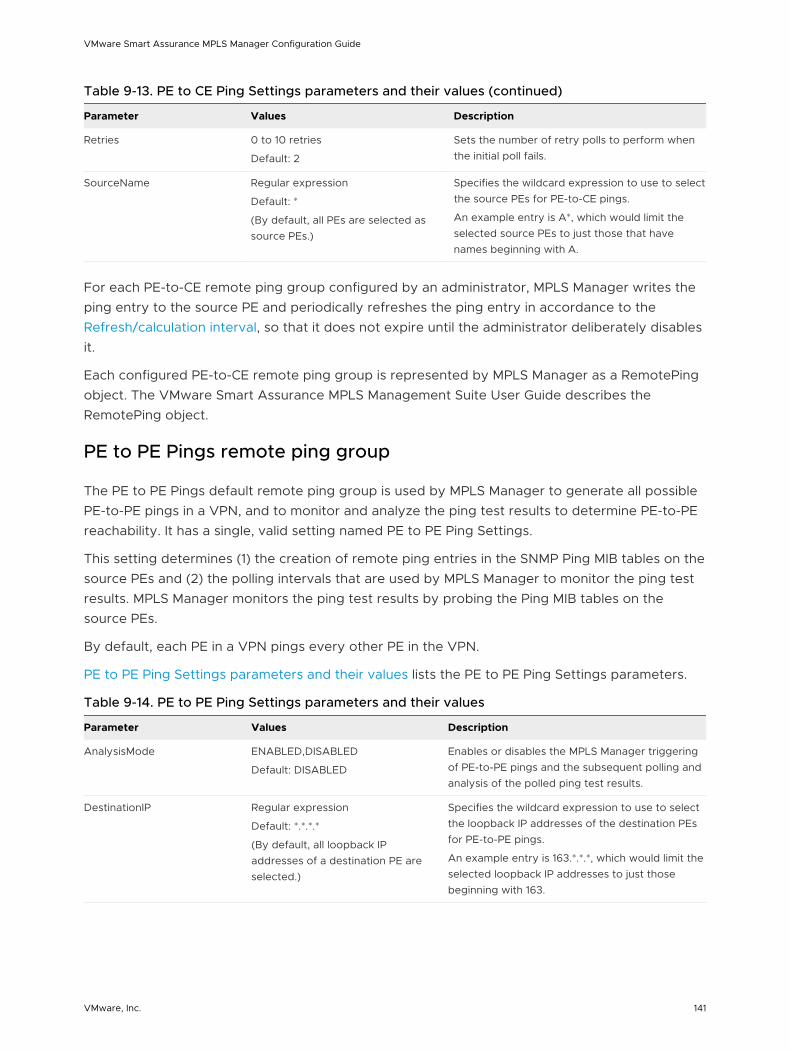
Table 9-13. PE to CE Ping Settings parameters and their values (continued)
Parameter Values Description
Retries 0 to 10 retries
Default: 2
Sets the number of retry polls to perform when the initial poll fails.
SourceName Regular expression
Default: *
(By default, all PEs are selected as source PEs.)
Specifies the wildcard expression to use to select the source PEs for PE-to-CE pings.
An example entry is A*, which would limit the selected source PEs to just those that have names beginning with A.
For each PE-to-CE remote ping group configured by an administrator, MPLS Manager writes the ping entry to the source PE and periodically refreshes the ping entry in accordance to the Refresh/calculation interval, so that it does not expire until the administrator deliberately disables it.
Each configured PE-to-CE remote ping group is represented by MPLS Manager as a RemotePing object. The VMware Smart Assurance MPLS Management Suite User Guide describes the RemotePing object.
PE to PE Pings remote ping group
The PE to PE Pings default remote ping group is used by MPLS Manager to generate all possible PE-to-PE pings in a VPN, and to monitor and analyze the ping test results to determine PE-to-PE reachability. It has a single, valid setting named PE to PE Ping Settings.
This setting determines (1) the creation of remote ping entries in the SNMP Ping MIB tables on the source PEs and (2) the polling intervals that are used by MPLS Manager to monitor the ping test results. MPLS Manager monitors the ping test results by probing the Ping MIB tables on the source PEs.
By default, each PE in a VPN pings every other PE in the VPN.
PE to PE Ping Settings parameters and their values lists the PE to PE Ping Settings parameters.
Table 9-14. PE to PE Ping Settings parameters and their values
Parameter Values Description
AnalysisMode ENABLED,DISABLED
Default: DISABLED
Enables or disables the MPLS Manager triggering of PE-to-PE pings and the subsequent polling and analysis of the polled ping test results.
DestinationIP Regular expression
Default: *.*.*.*
(By default, all loopback IP addresses of a destination PE are selected.)
Specifies the wildcard expression to use to select the loopback IP addresses of the destination PEs for PE-to-PE pings.
An example entry is 163.*.*.*, which would limit the selected loopback IP addresses to just those beginning with 163.
VMware Smart Assurance MPLS Manager Configuration Guide
VMware, Inc. 141
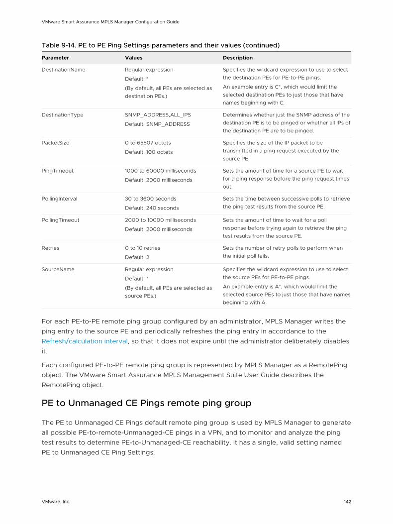
Table 9-14. PE to PE Ping Settings parameters and their values (continued)
Parameter Values Description
DestinationName Regular expression
Default: *
(By default, all PEs are selected as destination PEs.)
Specifies the wildcard expression to use to select the destination PEs for PE-to-PE pings.
An example entry is C*, which would limit the selected destination PEs to just those that have names beginning with C.
DestinationType SNMP_ADDRESS,ALL_IPS
Default: SNMP_ADDRESS
Determines whether just the SNMP address of the destination PE is to be pinged or whether all IPs of the destination PE are to be pinged.
PacketSize 0 to 65507 octets
Default: 100 octets
Specifies the size of the IP packet to be transmitted in a ping request executed by the source PE.
PingTimeout 1000 to 60000 milliseconds
Default: 2000 milliseconds
Sets the amount of time for a source PE to wait for a ping response before the ping request times out.
PollingInterval 30 to 3600 seconds
Default: 240 seconds
Sets the time between successive polls to retrieve the ping test results from the source PE.
PollingTimeout 2000 to 10000 milliseconds
Default: 2000 milliseconds
Sets the amount of time to wait for a poll response before trying again to retrieve the ping test results from the source PE.
Retries 0 to 10 retries
Default: 2
Sets the number of retry polls to perform when the initial poll fails.
SourceName Regular expression
Default: *
(By default, all PEs are selected as source PEs.)
Specifies the wildcard expression to use to select the source PEs for PE-to-PE pings.
An example entry is A*, which would limit the selected source PEs to just those that have names beginning with A.
For each PE-to-PE remote ping group configured by an administrator, MPLS Manager writes the ping entry to the source PE and periodically refreshes the ping entry in accordance to the Refresh/calculation interval, so that it does not expire until the administrator deliberately disables it.
Each configured PE-to-PE remote ping group is represented by MPLS Manager as a RemotePing object. The VMware Smart Assurance MPLS Management Suite User Guide describes the RemotePing object.
PE to Unmanaged CE Pings remote ping group
The PE to Unmanaged CE Pings default remote ping group is used by MPLS Manager to generate all possible PE-to-remote-Unmanaged-CE pings in a VPN, and to monitor and analyze the ping test results to determine PE-to-Unmanaged-CE reachability. It has a single, valid setting named PE to Unmanaged CE Ping Settings.
VMware Smart Assurance MPLS Manager Configuration Guide
VMware, Inc. 142
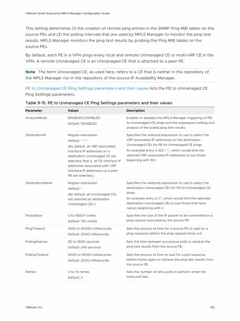
This setting determines (1) the creation of remote ping entries in the SNMP Ping MIB tables on the source PEs and (2) the polling intervals that are used by MPLS Manager to monitor the ping test results. MPLS Manager monitors the ping test results by probing the Ping MIB tables on the source PEs.
By default, each PE in a VPN pings every local and remote Unmanaged CE or multi-VRF CE in the VPN. A remote Unmanaged CE is an Unmanaged CE that is attached to a peer PE.
Note The term Unmanaged CE, as used here, refers to a CE that is neither in the repository of the MPLS Manager nor in the repository of the source IP Availability Manager.
PE to Unmanaged CE Ping Settings parameters and their values lists the PE to Unmanaged CE Ping Settings parameters.
Table 9-15. PE to Unmanaged CE Ping Settings parameters and their values
Parameter Values Description
AnalysisMode ENABLED,DISABLED
Default: DISABLED
Enables or disables the MPLS Manager triggering of PE-to-Unmanaged-CE pings and the subsequent polling and analysis of the polled ping test results.
DestinationIP Regular expression
Default: *.*.*.*
(By default, all VRF-associated interface IP addresses on a destination Unmanaged CE are selected; that is, all CE interface IP addresses associated with VRF interface IP addresses on a peer PE are selected.)
Specifies the wildcard expression to use to select the VRF-associated IP addresses on the destination Unmanaged CEs for PE-to-Unmanaged-CE pings.
An example entry is 163.*.*.*, which would limit the selected VRF-associated IP addresses to just those beginning with 163.
DestinationName Regular expression
Default: *
(By default, all Unmanaged CEs are selected as destination Unmanaged CEs.)
Specifies the wildcard expression to use to select the destination Unmanaged CEs for PE-to-Unmanaged-CE pings.
An example entry is C*, which would limit the selected destination Unmanaged CEs to just those that have names beginning with C.
PacketSize 0 to 65507 octets
Default: 100 octets
Specifies the size of the IP packet to be transmitted in a ping request executed by the source PE.
PingTimeout 1000 to 60000 milliseconds
Default: 2000 milliseconds
Sets the amount of time for a source PE to wait for a ping response before the ping request times out.
PollingInterval 30 to 3600 seconds
Default: 240 seconds
Sets the time between successive polls to retrieve the ping test results from the source PE.
PollingTimeout 2000 to 10000 milliseconds
Default: 2000 milliseconds
Sets the amount of time to wait for a poll response before trying again to retrieve the ping test results from the source PE.
Retries 0 to 10 retries
Default: 2
Sets the number of retry polls to perform when the initial poll fails.
VMware Smart Assurance MPLS Manager Configuration Guide
VMware, Inc. 143
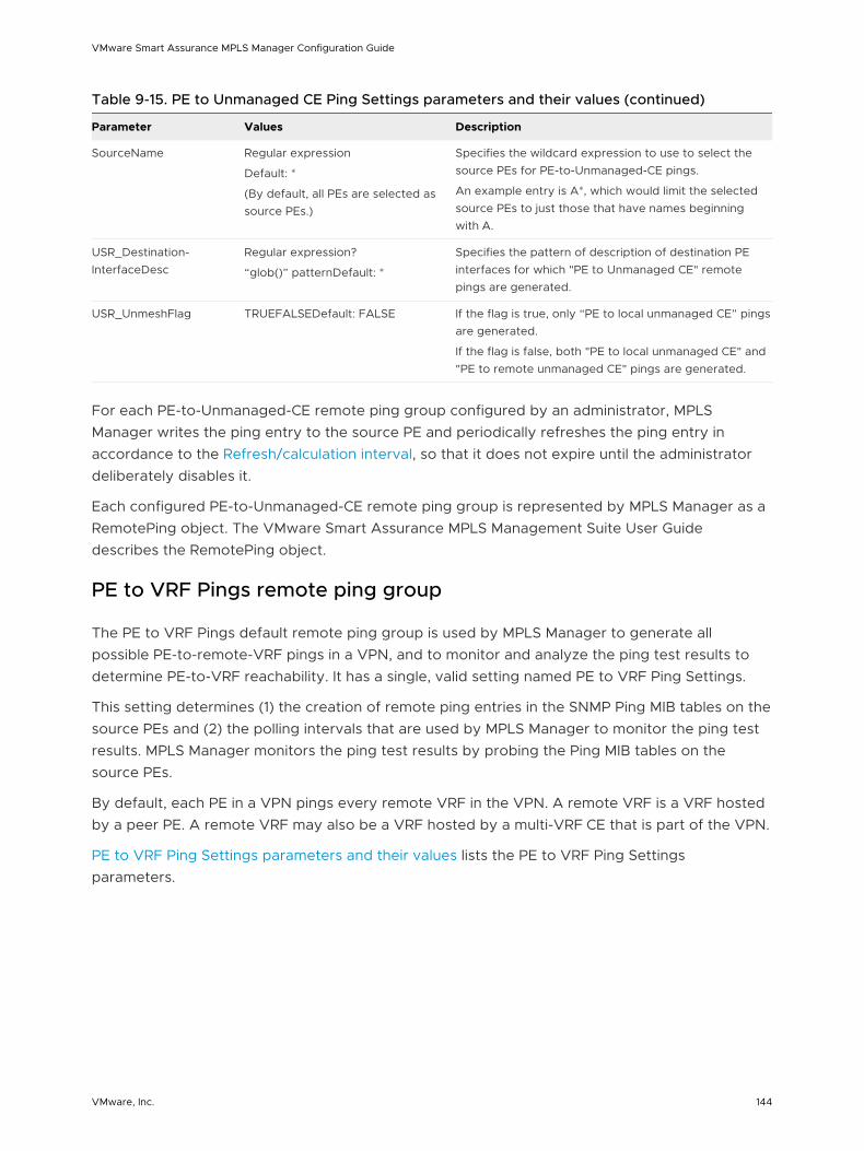
Table 9-15. PE to Unmanaged CE Ping Settings parameters and their values (continued)
Parameter Values Description
SourceName Regular expression
Default: *
(By default, all PEs are selected as source PEs.)
Specifies the wildcard expression to use to select the source PEs for PE-to-Unmanaged-CE pings.
An example entry is A*, which would limit the selected source PEs to just those that have names beginning with A.
USR_Destination-InterfaceDesc
Regular expression?
“glob()” patternDefault: *
Specifies the pattern of description of destination PE interfaces for which "PE to Unmanaged CE" remote pings are generated.
USR_UnmeshFlag TRUEFALSEDefault: FALSE If the flag is true, only “PE to local unmanaged CE” pings are generated.
If the flag is false, both "PE to local unmanaged CE" and "PE to remote unmanaged CE" pings are generated.
For each PE-to-Unmanaged-CE remote ping group configured by an administrator, MPLS Manager writes the ping entry to the source PE and periodically refreshes the ping entry in accordance to the Refresh/calculation interval, so that it does not expire until the administrator deliberately disables it.
Each configured PE-to-Unmanaged-CE remote ping group is represented by MPLS Manager as a RemotePing object. The VMware Smart Assurance MPLS Management Suite User Guide describes the RemotePing object.
PE to VRF Pings remote ping group
The PE to VRF Pings default remote ping group is used by MPLS Manager to generate all possible PE-to-remote-VRF pings in a VPN, and to monitor and analyze the ping test results to determine PE-to-VRF reachability. It has a single, valid setting named PE to VRF Ping Settings.
This setting determines (1) the creation of remote ping entries in the SNMP Ping MIB tables on the source PEs and (2) the polling intervals that are used by MPLS Manager to monitor the ping test results. MPLS Manager monitors the ping test results by probing the Ping MIB tables on the source PEs.
By default, each PE in a VPN pings every remote VRF in the VPN. A remote VRF is a VRF hosted by a peer PE. A remote VRF may also be a VRF hosted by a multi-VRF CE that is part of the VPN.
PE to VRF Ping Settings parameters and their values lists the PE to VRF Ping Settings parameters.
VMware Smart Assurance MPLS Manager Configuration Guide
VMware, Inc. 144
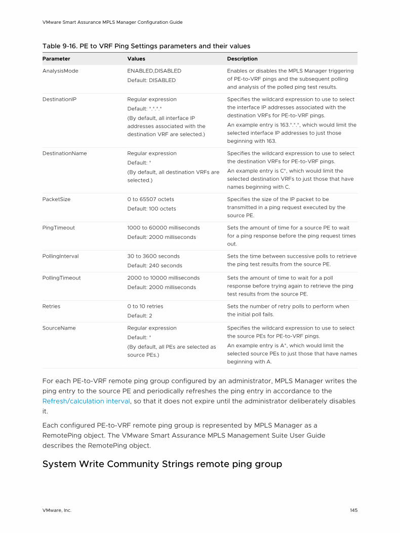
Table 9-16. PE to VRF Ping Settings parameters and their values
Parameter Values Description
AnalysisMode ENABLED,DISABLED
Default: DISABLED
Enables or disables the MPLS Manager triggering of PE-to-VRF pings and the subsequent polling and analysis of the polled ping test results.
DestinationIP Regular expression
Default: *.*.*.*
(By default, all interface IP addresses associated with the destination VRF are selected.)
Specifies the wildcard expression to use to select the interface IP addresses associated with the destination VRFs for PE-to-VRF pings.
An example entry is 163.*.*.*, which would limit the selected interface IP addresses to just those beginning with 163.
DestinationName Regular expression
Default: *
(By default, all destination VRFs are selected.)
Specifies the wildcard expression to use to select the destination VRFs for PE-to-VRF pings.
An example entry is C*, which would limit the selected destination VRFs to just those that have names beginning with C.
PacketSize 0 to 65507 octets
Default: 100 octets
Specifies the size of the IP packet to be transmitted in a ping request executed by the source PE.
PingTimeout 1000 to 60000 milliseconds
Default: 2000 milliseconds
Sets the amount of time for a source PE to wait for a ping response before the ping request times out.
PollingInterval 30 to 3600 seconds
Default: 240 seconds
Sets the time between successive polls to retrieve the ping test results from the source PE.
PollingTimeout 2000 to 10000 milliseconds
Default: 2000 milliseconds
Sets the amount of time to wait for a poll response before trying again to retrieve the ping test results from the source PE.
Retries 0 to 10 retries
Default: 2
Sets the number of retry polls to perform when the initial poll fails.
SourceName Regular expression
Default: *
(By default, all PEs are selected as source PEs.)
Specifies the wildcard expression to use to select the source PEs for PE-to-VRF pings.
An example entry is A*, which would limit the selected source PEs to just those that have names beginning with A.
For each PE-to-VRF remote ping group configured by an administrator, MPLS Manager writes the ping entry to the source PE and periodically refreshes the ping entry in accordance to the Refresh/calculation interval, so that it does not expire until the administrator deliberately disables it.
Each configured PE-to-VRF remote ping group is represented by MPLS Manager as a RemotePing object. The VMware Smart Assurance MPLS Management Suite User Guide describes the RemotePing object.
System Write Community Strings remote ping group
VMware Smart Assurance MPLS Manager Configuration Guide
VMware, Inc. 145
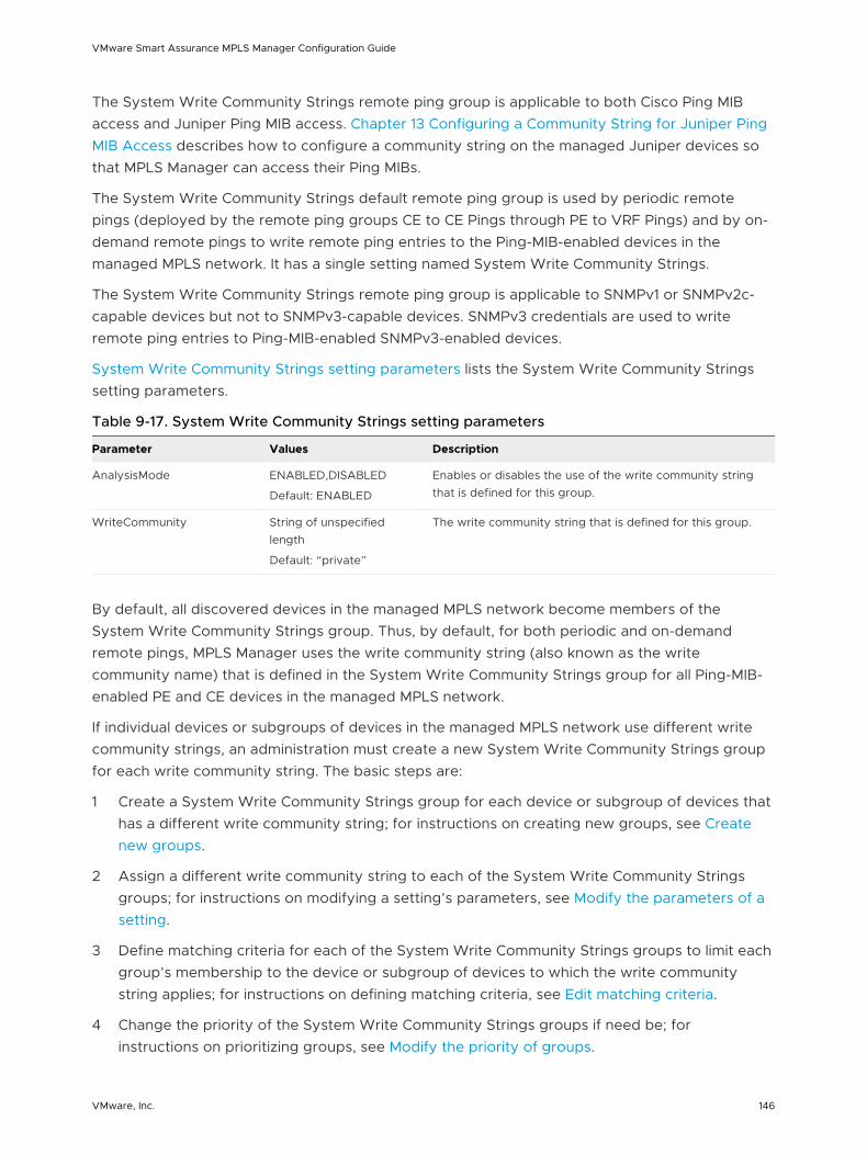
The System Write Community Strings remote ping group is applicable to both Cisco Ping MIB access and Juniper Ping MIB access. Chapter 13 Configuring a Community String for Juniper Ping MIB Access describes how to configure a community string on the managed Juniper devices so that MPLS Manager can access their Ping MIBs.
The System Write Community Strings default remote ping group is used by periodic remote pings (deployed by the remote ping groups CE to CE Pings through PE to VRF Pings) and by on-demand remote pings to write remote ping entries to the Ping-MIB-enabled devices in the managed MPLS network. It has a single setting named System Write Community Strings.
The System Write Community Strings remote ping group is applicable to SNMPv1 or SNMPv2c-capable devices but not to SNMPv3-capable devices. SNMPv3 credentials are used to write remote ping entries to Ping-MIB-enabled SNMPv3-enabled devices.
System Write Community Strings setting parameters lists the System Write Community Strings setting parameters.
Table 9-17. System Write Community Strings setting parameters
Parameter Values Description
AnalysisMode ENABLED,DISABLED
Default: ENABLED
Enables or disables the use of the write community string that is defined for this group.
WriteCommunity String of unspecified length
Default: “private”
The write community string that is defined for this group.
By default, all discovered devices in the managed MPLS network become members of the System Write Community Strings group. Thus, by default, for both periodic and on-demand remote pings, MPLS Manager uses the write community string (also known as the write community name) that is defined in the System Write Community Strings group for all Ping-MIB-enabled PE and CE devices in the managed MPLS network.
If individual devices or subgroups of devices in the managed MPLS network use different write community strings, an administration must create a new System Write Community Strings group for each write community string. The basic steps are:
1 Create a System Write Community Strings group for each device or subgroup of devices that has a different write community string; for instructions on creating new groups, see Create new groups.
2 Assign a different write community string to each of the System Write Community Strings groups; for instructions on modifying a setting’s parameters, see Modify the parameters of a setting.
3 Define matching criteria for each of the System Write Community Strings groups to limit each group’s membership to the device or subgroup of devices to which the write community string applies; for instructions on defining matching criteria, see Edit matching criteria.
4 Change the priority of the System Write Community Strings groups if need be; for instructions on prioritizing groups, see Modify the priority of groups.
VMware Smart Assurance MPLS Manager Configuration Guide
VMware, Inc. 146
To write a ping entry to a device, MPLS Manager searches through the prioritized list of System Write Community Strings groups for a device match, finds a match, includes the associated write community string in the remote ping request, and sends the request to the device. If no match is found, MPLS Manager includes the global write community string that is defined in the REMOTEPING.conf file in the remote ping request. The REMOTEPING.conf file is described in “Description of REMOTEPING.conf” on page 40.
RemotePing External Setting
The RemotePing External Setting is available to the following four remote ping groups: PE to CE, PE to PE, PE to Unmanaged CE, and PE to VRF. The setting serves two purposes:
n Provides a means of testing the remote ping instrumentation and analysis functionality of MPLS Manager.
n Provides a means for MPLS Manager to import remote ping status updates from an VMware Smart Assurance adapter, such as the VMware Smart Assurance Adapter for Alcatel-Lucent 5620 SAM EMS.
RemotePing External Setting parameters and their values lists the RemotePing External Setting parameters.
VMware Smart Assurance MPLS Manager Configuration Guide
VMware, Inc. 147
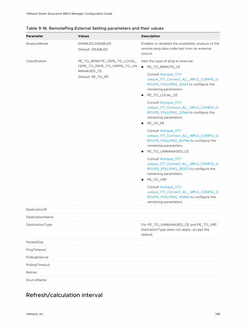
Table 9-18. RemotePing External Setting parameters and their values
Parameter Values Description
AnalysisMode ENABLED,DISABLED
Default: DISABLED
Enables or disables the availability analysis of the remote ping data collected from an external source.
Classification PE_TO_REMOTE_CEPE_TO_LOCAL_CEPE_TO_PEPE_TO_VRFPE_TO_UNMANAGED_CE
Default: PE_TO_PE
Sets the type of ping to execute:
n PE_TO_REMOTE_CE
Consult #unique_177/unique_177_Connect_42__MPLS_CONFIG_GROUPS_POLLPING_33144 to configure the remaining parameters.
n PE_TO_LOCAL_CE
Consult #unique_177/unique_177_Connect_42__MPLS_CONFIG_GROUPS_POLLPING_33144 to configure the remaining parameters.
n PE_TO_PE
Consult #unique_177/unique_177_Connect_42__MPLS_CONFIG_GROUPS_POLLPING_60794 to configure the remaining parameters.
n PE_TO_UNMANAGED_CE
Consult #unique_177/unique_177_Connect_42__MPLS_CONFIG_GROUPS_POLLPING_39323 to configure the remaining parameters.
n PE_TO_VRF
Consult #unique_177/unique_177_Connect_42__MPLS_CONFIG_GROUPS_POLLPING_46969 to configure the remaining parameters.
DestinationIP
DestinationName
DestinationType For PE_TO_UNMANAGED_CE and PE_TO_VRF, DetinationType does not apply; accept the default.
PacketSize
PingTimeout
PollingInterval
PollingTimeout
Retries
SourceName
Refresh/calculation interval
VMware Smart Assurance MPLS Manager Configuration Guide
VMware, Inc. 148
MPLS Manager performs a refresh and a remote ping event (Down, Impaired) calculation in accordance to the following user-defined interval:
Interval = RefreshFactor*PollingInterval
The RefreshFactor parameter, described in #unique_172/unique_172_Connect_42__MPLS_CONFIG_MPLS_97913, has a default value of 3. Thus, by default, the refresh/calculation interval is 720 seconds (3 x 240 seconds).
When MPLS Manager refreshes the remote ping entry on the source device, it destroys the existing remote ping entry in the device’s PING MIB table and creates a new one. It also sets the TimeRefreshed attribute of the associated RemotePing object to the current time.
The remote ping entries on the source devices are destroyed when the associated RemotePing objects are deleted in MPLS Manager. In addition, users can destroy remote ping entries on the source devices by disabling the RemotePing objects in MPLS Manager before shutting down MPLS Manager.
VMware Smart Assurance MPLS Manager Configuration Guide
VMware, Inc. 149
Building CLI-Based Server Tools on the CLI Framework 10This chapter includes the following topics:
n CLI tool framework overview
n CLI-based server tool files
n CLI-based server-tool development tasks
n Making the server tool available to console users
n Writing the tool scripts for a CLI-based server tool
CLI tool framework overview
The purpose of the discussion is to explain how to use the CLI tool framework to develop CLI-based server tools such as LSP ping. MPLS Manager’s LSP ping serves as an example throughout the discussion.
Note LSP ping is available for Layer 2 and Layer 3 VPNs and is applicable to label switched paths (LSPs) that are constructed by using the Label Distribution Protocol.
The CLI tool framework consists of a Global Manager component and one or more Domain Manager components. The framework is responsible for setting up Telnet, SSH1, or SSH2 command line interface (CLI) connections to devices in the managed network. The connections are set up when running CLI-based server tools.
Server tools are programs that are invoked by a user through a Global Console that is attached to the Global Manager. Upon right-clicking a notification, a topology object, or a map object to display a pop-up menu, a user may invoke any of the server tools that are listed on the menu.
Although most server tools are invoked and executed on the host where the Global Manager is running, CLI-based server tools are different in the sense that they are invoked on the host where the Global Manager is running but executed on the host where an underlying Domain Manager is running. The LSP ping server tools that are described in the VMware Smart Assurance MPLS Management Suite User Guide demonstrate this type of behavior.
CLI-based server tool files
VMware, Inc. 150
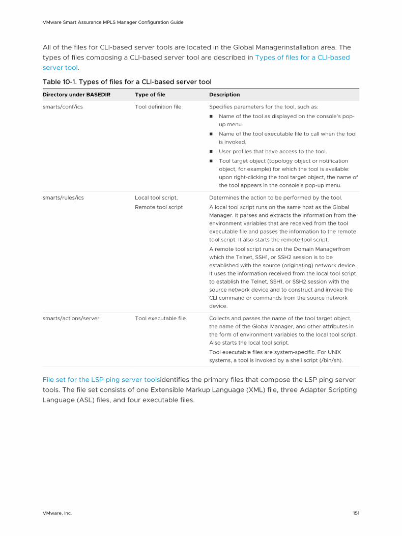
All of the files for CLI-based server tools are located in the Global Managerinstallation area. The types of files composing a CLI-based server tool are described in Types of files for a CLI-based server tool.
Table 10-1. Types of files for a CLI-based server tool
Directory under BASEDIR Type of file Description
smarts/conf/ics Tool definition file Specifies parameters for the tool, such as:
n Name of the tool as displayed on the console’s pop-up menu.
n Name of the tool executable file to call when the tool is invoked.
n User profiles that have access to the tool.
n Tool target object (topology object or notification object, for example) for which the tool is available: upon right-clicking the tool target object, the name of the tool appears in the console’s pop-up menu.
smarts/rules/ics Local tool script,
Remote tool script
Determines the action to be performed by the tool.
A local tool script runs on the same host as the Global Manager. It parses and extracts the information from the environment variables that are received from the tool executable file and passes the information to the remote tool script. It also starts the remote tool script.
A remote tool script runs on the Domain Managerfrom which the Telnet, SSH1, or SSH2 session is to be established with the source (originating) network device. It uses the information received from the local tool script to establish the Telnet, SSH1, or SSH2 session with the source network device and to construct and invoke the CLI command or commands from the source network device.
smarts/actions/server Tool executable file Collects and passes the name of the tool target object, the name of the Global Manager, and other attributes in the form of environment variables to the local tool script. Also starts the local tool script.
Tool executable files are system-specific. For UNIX systems, a tool is invoked by a shell script (/bin/sh).
File set for the LSP ping server toolsidentifies the primary files that compose the LSP ping server tools. The file set consists of one Extensible Markup Language (XML) file, three Adapter Scripting Language (ASL) files, and four executable files.
VMware Smart Assurance MPLS Manager Configuration Guide
VMware, Inc. 151
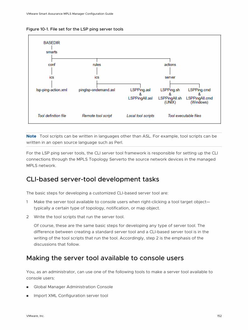
Figure 10-1. File set for the LSP ping server tools
Note Tool scripts can be written in languages other than ASL. For example, tool scripts can be written in an open source language such as Perl.
For the LSP ping server tools, the CLI server tool framework is responsible for setting up the CLI connections through the MPLS Topology Serverto the source network devices in the managed MPLS network.
CLI-based server-tool development tasks
The basic steps for developing a customized CLI-based server tool are:
1 Make the server tool available to console users when right-clicking a tool target object—typically a certain type of topology, notification, or map object.
2 Write the tool scripts that run the server tool.
Of course, these are the same basic steps for developing any type of server tool. The difference between creating a standard server tool and a CLI-based server tool is in the writing of the tool scripts that run the tool. Accordingly, step 2 is the emphasis of the discussions that follow.
Making the server tool available to console users
You, as an administrator, can use one of the following tools to make a server tool available to console users:
n Global Manager Administration Console
n Import XML Configuration server tool
VMware Smart Assurance MPLS Manager Configuration Guide
VMware, Inc. 152
Global Manager Administration Console method
Using the Global Manager Administration Console, you create an XML file that defines the following configuration parameters for a server tool:
n Name
Specifies the name of the server tool as it appears on the console’s pop-up menu.
n Program
Specifies the name of the tool executable file that is invoked when this tool runs.
n Timeout
Specifies the number of seconds to wait for the tool script to complete.
n Trace
Specifies whether trace output, used for debugging, should display in the tool output window when this tool runs.
n DisplayOutput
Specifies whether the tool script should open an output window when this tool runs.
n User Profiles
Specifies the user profiles that have access to this tool.
n Context
Specifies the tool target objects for this tool.
n Status
Specifies whether this tool is enabled or disabled.
Clicking the Finish button completes the creation of the XML file in the BASEDIR/smarts/conf/ics directory and makes the server tool available to console users.
The VMware Smart Assurance Service Assurance Manager Configuration Guide provides detailed description on how to use the Global Manager Administration Console to create XML files for server tools.
Import XML Configuration server tool method
To use the Import XML Configuration server tool to make a server tool available to console users, the XML file for the server tool must already exist. The simplest way to create the XML file is through the Global Manager Administration Console, as just described. You can also use one of the template XML files in the BASEDIR/smarts/conf/ics directory in the Global Manager installation area to create the XML file.
The XML file for the three LSP ping server tools, “LSP Ping,” “LSP Ping All,” and “VRF LSP Ping All,” is named lsp-ping-action.xml.
VMware Smart Assurance MPLS Manager Configuration Guide
VMware, Inc. 153
To import the lsp-ping-action.xml file into the Global Manager by using the Import XML Configuration server tool, follow the procedure given in “Enabling the use of MPLS remote ping and LSP ping server tools” on page 100.
Upon importing the lsp-ping-action.xml file into the Global Manager, the LSP ping server tools are available to console users. Console users that are already attached to the Global Manager must detach and reattach the Global Console to the Global Manager in order to see the LSP ping server tool options on the pop-up menu.
The VMware Smart Assurance Service Assurance Manager Configuration Guide provides more information about using the Import XML Configuration server tool to import XML files into the Global Manager repository.
Writing the tool scripts for a CLI-based server tool
Once you have determined the action to be performed by the CLI-based server tool, perform the following tasks to create the tool scripts and auxiliary files for the tool:
n Create the system-specific tool execution files for the tool.
n Write the local and remote tool scripts to accomplish the determined action for the tool.
n Assign the proper read/execute permissions to the tool scripts.
n Save the tool execution files to the BASEDIR/smarts/actions/server directory and the tool scripts to the BASEDIR/smarts/rules/ics directory.
n Test the tool to ensure that it executes properly.
The LSP ping flow shown in LSP ping flowchart helps clarify the following sequence of events executed by a CLI-based server tool when the tool is invoked:
a Start the local and remote tool scripts.
b Acquire the appropriate login credentials to access the source (originating) network device, invoke the desired CLI command or commands, and save the results to a data file.
c Read the results in the data file, parse and analyze the results, and report the results to the initiator of the tool.
VMware Smart Assurance MPLS Manager Configuration Guide
VMware, Inc. 154
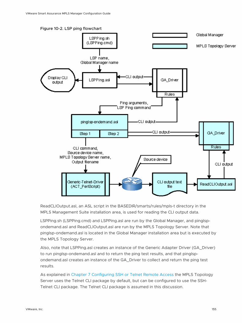
Figure 10-2. LSP ping flowchart
ReadCLIOutput.asl, an ASL script in the BASEDIR/smarts/rules/mpls-t directory in the MPLS Management Suite installation area, is used for reading the CLI output data.
LSPPing.sh (LSPPing.cmd) and LSPPing.asl are run by the Global Manager, and pinglsp-ondemand.asl and ReadCLIOutput.asl are run by the MPLS Topology Server. Note that pinglsp-ondemand.asl is located in the Global Manager installation area but is executed by the MPLS Topology Server.
Also, note that LSPPing.asl creates an instance of the Generic Adapter Driver (GA_Driver) to run pinglsp-ondemand.asl and to return the ping test results, and that pinglsp-ondemand.asl creates an instance of the GA_Driver to collect and return the ping test results.
As explained in Chapter 7 Configuring SSH or Telnet Remote Access the MPLS Topology Server uses the Telnet CLI package by default, but can be configured to use the SSH-Telnet CLI package. The Telnet CLI package is assumed in this discussion.
VMware Smart Assurance MPLS Manager Configuration Guide
VMware, Inc. 155
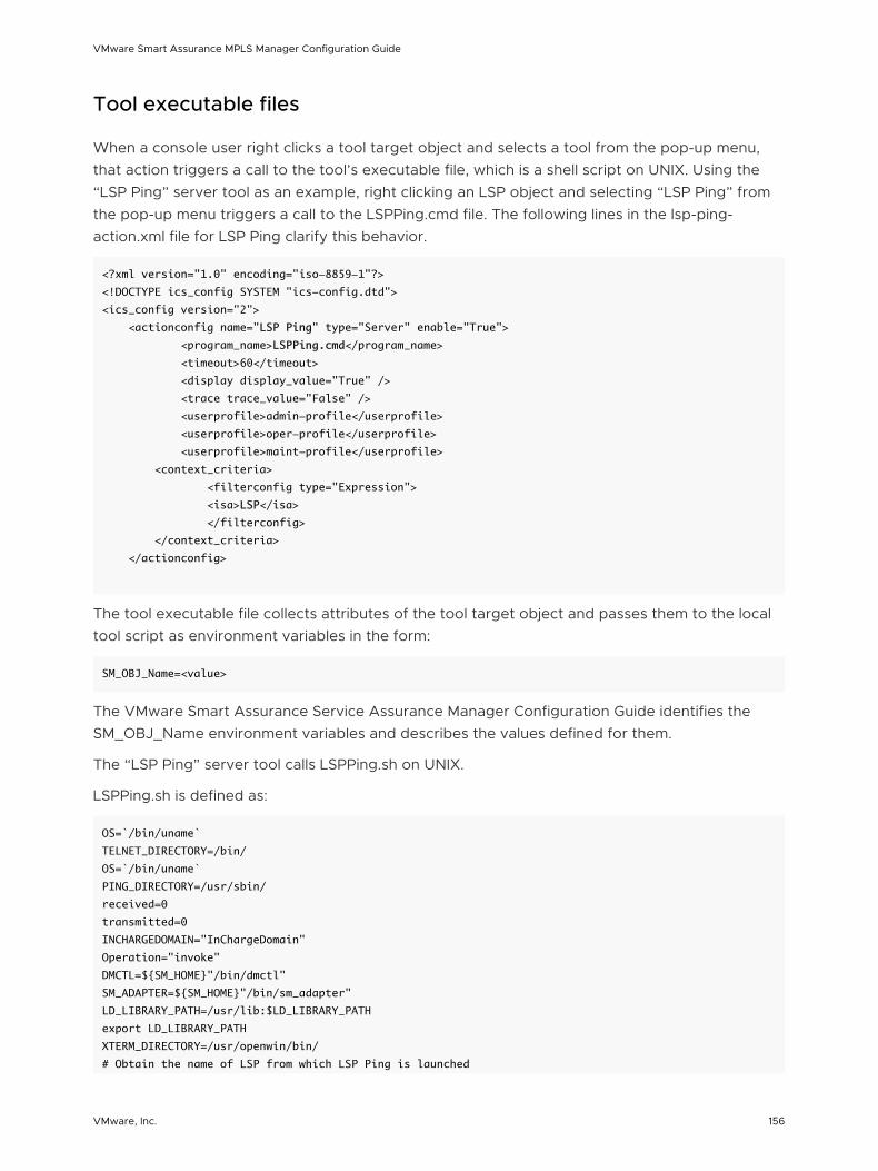
Tool executable files
When a console user right clicks a tool target object and selects a tool from the pop-up menu, that action triggers a call to the tool’s executable file, which is a shell script on UNIX. Using the “LSP Ping” server tool as an example, right clicking an LSP object and selecting “LSP Ping” from the pop-up menu triggers a call to the LSPPing.cmd file. The following lines in the lsp-ping-action.xml file for LSP Ping clarify this behavior.
<?xml version="1.0" encoding="iso-8859-1"?>
<!DOCTYPE ics_config SYSTEM "ics-config.dtd">
<ics_config version="2">
<actionconfig name="LSP Ping" type="Server" enable="True">
<program_name>LSPPing.cmd</program_name>
<timeout>60</timeout>
<display display_value="True" />
<trace trace_value="False" />
<userprofile>admin-profile</userprofile>
<userprofile>oper-profile</userprofile>
<userprofile>maint-profile</userprofile>
<context_criteria>
<filterconfig type="Expression">
<isa>LSP</isa>
</filterconfig>
</context_criteria>
</actionconfig>
The tool executable file collects attributes of the tool target object and passes them to the local tool script as environment variables in the form:
SM_OBJ_Name=<value>
The VMware Smart Assurance Service Assurance Manager Configuration Guide identifies the SM_OBJ_Name environment variables and describes the values defined for them.
The “LSP Ping” server tool calls LSPPing.sh on UNIX.
LSPPing.sh is defined as:
OS=`/bin/uname`
TELNET_DIRECTORY=/bin/
OS=`/bin/uname`
PING_DIRECTORY=/usr/sbin/
received=0
transmitted=0
INCHARGEDOMAIN="InChargeDomain"
Operation="invoke"
DMCTL=${SM_HOME}"/bin/dmctl"
SM_ADAPTER=${SM_HOME}"/bin/sm_adapter"
LD_LIBRARY_PATH=/usr/lib:$LD_LIBRARY_PATH
export LD_LIBRARY_PATH
XTERM_DIRECTORY=/usr/openwin/bin/
# Obtain the name of LSP from which LSP Ping is launched
VMware Smart Assurance MPLS Manager Configuration Guide
VMware, Inc. 156
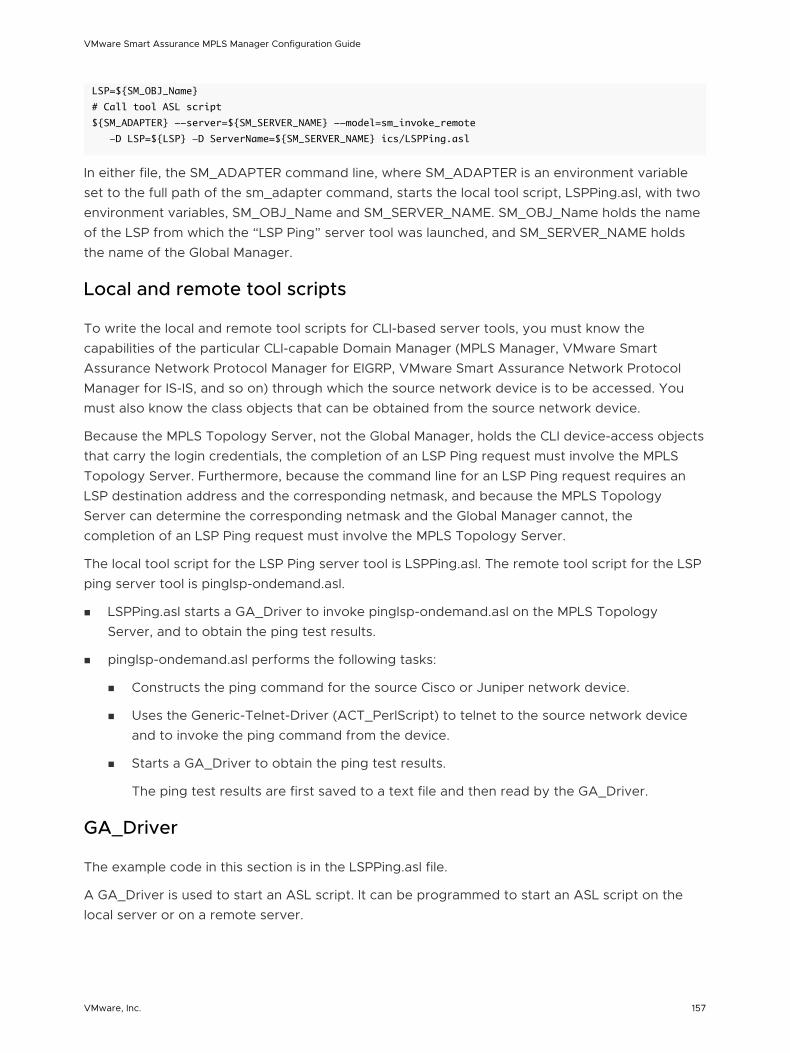
LSP=${SM_OBJ_Name}
# Call tool ASL script
${SM_ADAPTER} --server=${SM_SERVER_NAME} --model=sm_invoke_remote
-D LSP=${LSP} -D ServerName=${SM_SERVER_NAME} ics/LSPPing.asl
In either file, the SM_ADAPTER command line, where SM_ADAPTER is an environment variable set to the full path of the sm_adapter command, starts the local tool script, LSPPing.asl, with two environment variables, SM_OBJ_Name and SM_SERVER_NAME. SM_OBJ_Name holds the name of the LSP from which the “LSP Ping” server tool was launched, and SM_SERVER_NAME holds the name of the Global Manager.
Local and remote tool scripts
To write the local and remote tool scripts for CLI-based server tools, you must know the capabilities of the particular CLI-capable Domain Manager (MPLS Manager, VMware Smart Assurance Network Protocol Manager for EIGRP, VMware Smart Assurance Network Protocol Manager for IS-IS, and so on) through which the source network device is to be accessed. You must also know the class objects that can be obtained from the source network device.
Because the MPLS Topology Server, not the Global Manager, holds the CLI device-access objects that carry the login credentials, the completion of an LSP Ping request must involve the MPLS Topology Server. Furthermore, because the command line for an LSP Ping request requires an LSP destination address and the corresponding netmask, and because the MPLS Topology Server can determine the corresponding netmask and the Global Manager cannot, the completion of an LSP Ping request must involve the MPLS Topology Server.
The local tool script for the LSP Ping server tool is LSPPing.asl. The remote tool script for the LSP ping server tool is pinglsp-ondemand.asl.
n LSPPing.asl starts a GA_Driver to invoke pinglsp-ondemand.asl on the MPLS Topology Server, and to obtain the ping test results.
n pinglsp-ondemand.asl performs the following tasks:
n Constructs the ping command for the source Cisco or Juniper network device.
n Uses the Generic-Telnet-Driver (ACT_PerlScript) to telnet to the source network device and to invoke the ping command from the device.
n Starts a GA_Driver to obtain the ping test results.
The ping test results are first saved to a text file and then read by the GA_Driver.
GA_Driver
The example code in this section is in the LSPPing.asl file.
A GA_Driver is used to start an ASL script. It can be programmed to start an ASL script on the local server or on a remote server.
VMware Smart Assurance MPLS Manager Configuration Guide
VMware, Inc. 157
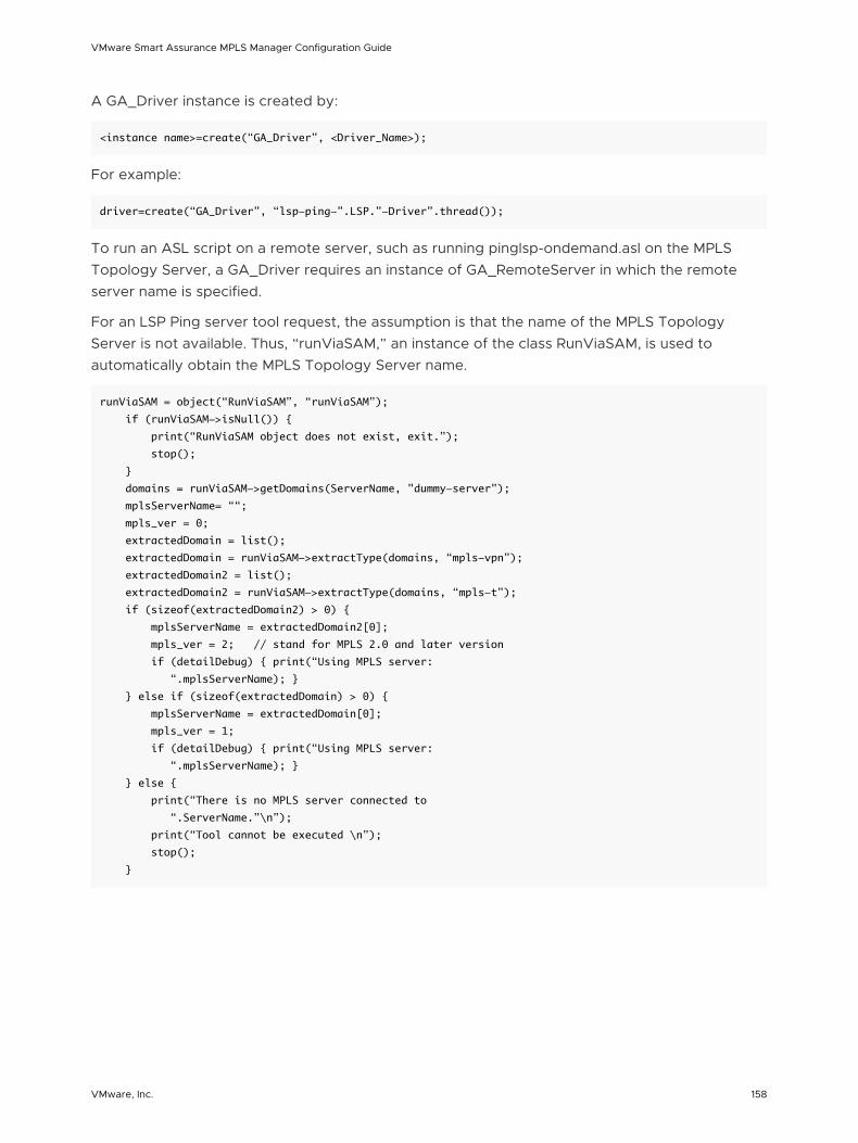
A GA_Driver instance is created by:
<instance name>=create(“GA_Driver”, <Driver_Name>);
For example:
driver=create(“GA_Driver”, “lsp-ping-”.LSP.”-Driver”.thread());
To run an ASL script on a remote server, such as running pinglsp-ondemand.asl on the MPLS Topology Server, a GA_Driver requires an instance of GA_RemoteServer in which the remote server name is specified.
For an LSP Ping server tool request, the assumption is that the name of the MPLS Topology Server is not available. Thus, “runViaSAM,” an instance of the class RunViaSAM, is used to automatically obtain the MPLS Topology Server name.
runViaSAM = object(“RunViaSAM”, “runViaSAM”);
if (runViaSAM->isNull()) {
print(“RunViaSAM object does not exist, exit.”);
stop();
}
domains = runViaSAM->getDomains(ServerName, "dummy-server");
mplsServerName= ““;
mpls_ver = 0;
extractedDomain = list();
extractedDomain = runViaSAM->extractType(domains, “mpls-vpn”);
extractedDomain2 = list();
extractedDomain2 = runViaSAM->extractType(domains, “mpls-t”);
if (sizeof(extractedDomain2) > 0) {
mplsServerName = extractedDomain2[0];
mpls_ver = 2; // stand for MPLS 2.0 and later version
if (detailDebug) { print(“Using MPLS server:
“.mplsServerName); }
} else if (sizeof(extractedDomain) > 0) {
mplsServerName = extractedDomain[0];
mpls_ver = 1;
if (detailDebug) { print(“Using MPLS server:
“.mplsServerName); }
} else {
print(“There is no MPLS server connected to
“.ServerName.”\n”);
print(“Tool cannot be executed \n”);
stop();
}
VMware Smart Assurance MPLS Manager Configuration Guide
VMware, Inc. 158
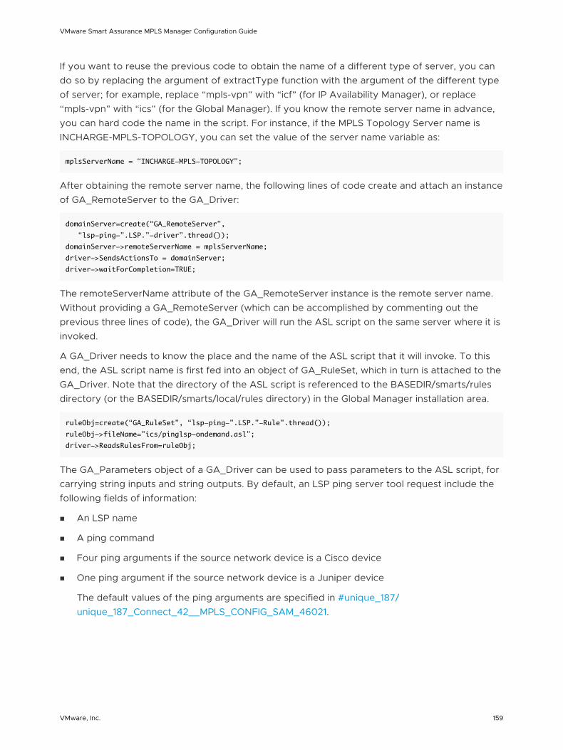
If you want to reuse the previous code to obtain the name of a different type of server, you can do so by replacing the argument of extractType function with the argument of the different type of server; for example, replace “mpls-vpn” with “icf” (for IP Availability Manager), or replace “mpls-vpn” with “ics” (for the Global Manager). If you know the remote server name in advance, you can hard code the name in the script. For instance, if the MPLS Topology Server name is INCHARGE-MPLS-TOPOLOGY, you can set the value of the server name variable as:
mplsServerName = “INCHARGE-MPLS-TOPOLOGY”;
After obtaining the remote server name, the following lines of code create and attach an instance of GA_RemoteServer to the GA_Driver:
domainServer=create(“GA_RemoteServer”,
“lsp-ping-”.LSP.”-driver”.thread());
domainServer->remoteServerName = mplsServerName;
driver->SendsActionsTo = domainServer;
driver->waitForCompletion=TRUE;
The remoteServerName attribute of the GA_RemoteServer instance is the remote server name. Without providing a GA_RemoteServer (which can be accomplished by commenting out the previous three lines of code), the GA_Driver will run the ASL script on the same server where it is invoked.
A GA_Driver needs to know the place and the name of the ASL script that it will invoke. To this end, the ASL script name is first fed into an object of GA_RuleSet, which in turn is attached to the GA_Driver. Note that the directory of the ASL script is referenced to the BASEDIR/smarts/rules directory (or the BASEDIR/smarts/local/rules directory) in the Global Manager installation area.
ruleObj=create(“GA_RuleSet”, “lsp-ping-”.LSP.”-Rule”.thread());
ruleObj->fileName=”ics/pinglsp-ondemand.asl”;
driver->ReadsRulesFrom=ruleObj;
The GA_Parameters object of a GA_Driver can be used to pass parameters to the ASL script, for carrying string inputs and string outputs. By default, an LSP ping server tool request include the following fields of information:
n An LSP name
n A ping command
n Four ping arguments if the source network device is a Cisco device
n One ping argument if the source network device is a Juniper device
The default values of the ping arguments are specified in #unique_187/unique_187_Connect_42__MPLS_CONFIG_SAM_46021.
VMware Smart Assurance MPLS Manager Configuration Guide
VMware, Inc. 159
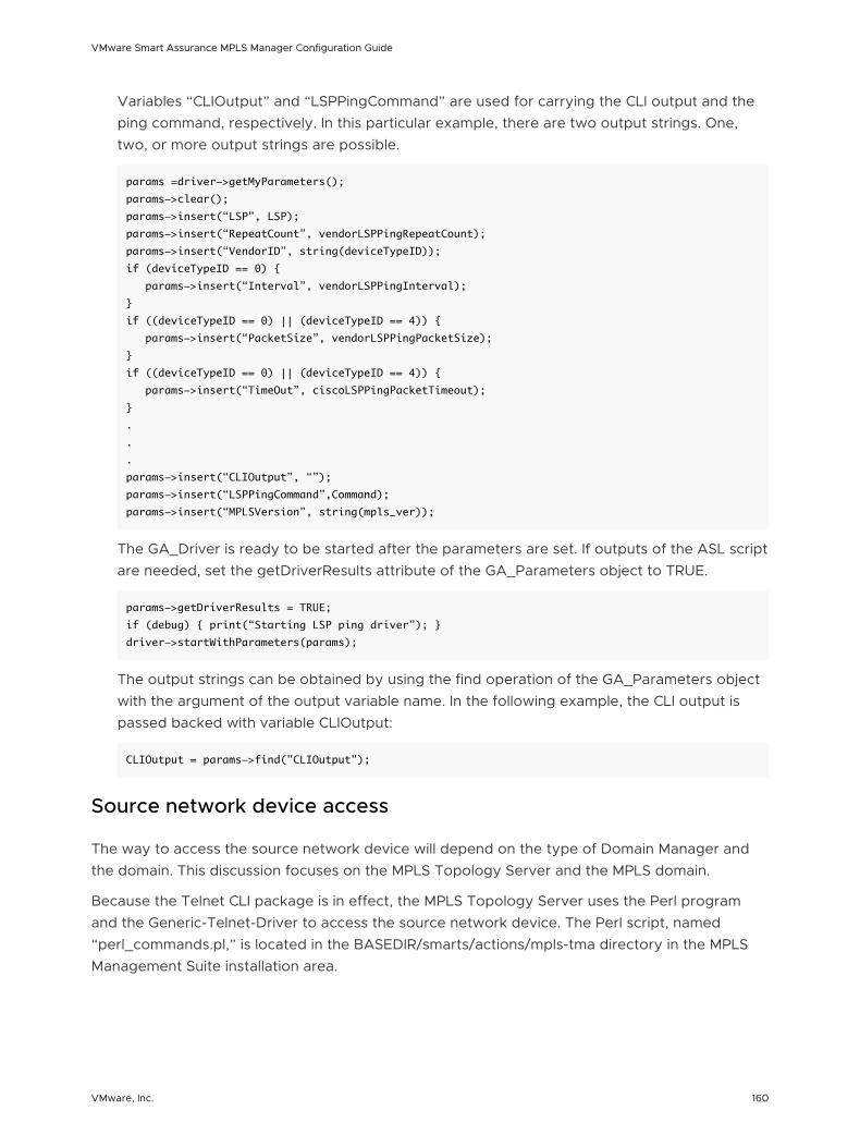
Variables “CLIOutput” and “LSPPingCommand” are used for carrying the CLI output and the ping command, respectively. In this particular example, there are two output strings. One, two, or more output strings are possible.
params =driver->getMyParameters();
params->clear();
params->insert(“LSP”, LSP);
params->insert(“RepeatCount”, vendorLSPPingRepeatCount);
params->insert(“VendorID”, string(deviceTypeID));
if (deviceTypeID == 0) {
params->insert(“Interval”, vendorLSPPingInterval);
}
if ((deviceTypeID == 0) || (deviceTypeID == 4)) {
params->insert(“PacketSize”, vendorLSPPingPacketSize);
}
if ((deviceTypeID == 0) || (deviceTypeID == 4)) {
params->insert(“TimeOut”, ciscoLSPPingPacketTimeout);
}
.
.
.
params->insert(“CLIOutput”, “”);
params->insert(“LSPPingCommand”,Command);
params->insert(“MPLSVersion”, string(mpls_ver));
The GA_Driver is ready to be started after the parameters are set. If outputs of the ASL script are needed, set the getDriverResults attribute of the GA_Parameters object to TRUE.
params->getDriverResults = TRUE;
if (debug) { print(“Starting LSP ping driver”); }
driver->startWithParameters(params);
The output strings can be obtained by using the find operation of the GA_Parameters object with the argument of the output variable name. In the following example, the CLI output is passed backed with variable CLIOutput:
CLIOutput = params->find("CLIOutput");
Source network device access
The way to access the source network device will depend on the type of Domain Manager and the domain. This discussion focuses on the MPLS Topology Server and the MPLS domain.
Because the Telnet CLI package is in effect, the MPLS Topology Server uses the Perl program and the Generic-Telnet-Driver to access the source network device. The Perl script, named “perl_commands.pl,” is located in the BASEDIR/smarts/actions/mpls-tma directory in the MPLS Management Suite installation area.
VMware Smart Assurance MPLS Manager Configuration Guide
VMware, Inc. 160
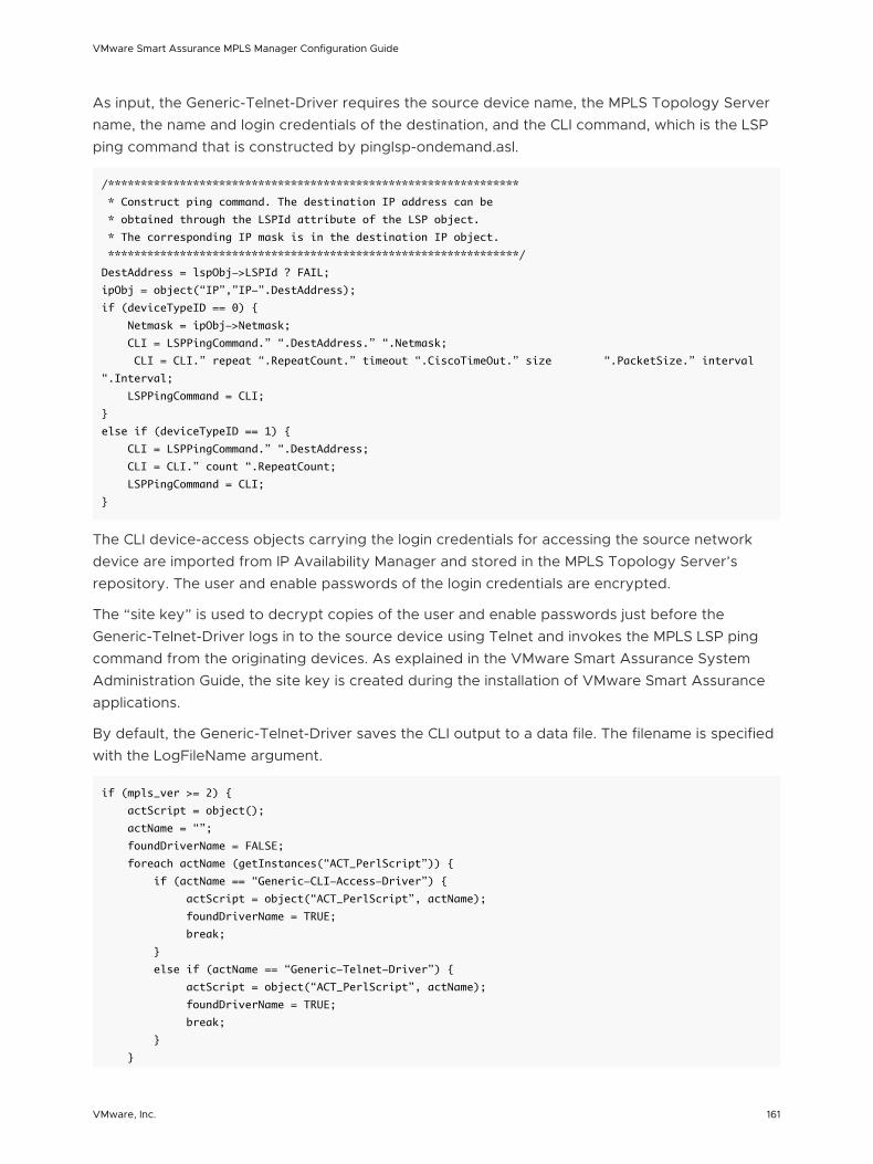
As input, the Generic-Telnet-Driver requires the source device name, the MPLS Topology Server name, the name and login credentials of the destination, and the CLI command, which is the LSP ping command that is constructed by pinglsp-ondemand.asl.
/***************************************************************
* Construct ping command. The destination IP address can be
* obtained through the LSPId attribute of the LSP object.
* The corresponding IP mask is in the destination IP object.
***************************************************************/
DestAddress = lspObj->LSPId ? FAIL;
ipObj = object(“IP”,”IP-”.DestAddress);
if (deviceTypeID == 0) {
Netmask = ipObj->Netmask;
CLI = LSPPingCommand.” “.DestAddress.” “.Netmask;
CLI = CLI.” repeat “.RepeatCount.” timeout “.CiscoTimeOut.” size “.PacketSize.” interval
“.Interval;
LSPPingCommand = CLI;
}
else if (deviceTypeID == 1) {
CLI = LSPPingCommand.” “.DestAddress;
CLI = CLI.” count “.RepeatCount;
LSPPingCommand = CLI;
}
The CLI device-access objects carrying the login credentials for accessing the source network device are imported from IP Availability Manager and stored in the MPLS Topology Server’s repository. The user and enable passwords of the login credentials are encrypted.
The “site key” is used to decrypt copies of the user and enable passwords just before the Generic-Telnet-Driver logs in to the source device using Telnet and invokes the MPLS LSP ping command from the originating devices. As explained in the VMware Smart Assurance System Administration Guide, the site key is created during the installation of VMware Smart Assurance applications.
By default, the Generic-Telnet-Driver saves the CLI output to a data file. The filename is specified with the LogFileName argument.
if (mpls_ver >= 2) {
actScript = object();
actName = “”;
foundDriverName = FALSE;
foreach actName (getInstances(“ACT_PerlScript”)) {
if (actName == “Generic-CLI-Access-Driver”) {
actScript = object(“ACT_PerlScript”, actName);
foundDriverName = TRUE;
break;
}
else if (actName == “Generic-Telnet-Driver”) {
actScript = object(“ACT_PerlScript”, actName);
foundDriverName = TRUE;
break;
}
}
VMware Smart Assurance MPLS Manager Configuration Guide
VMware, Inc. 161
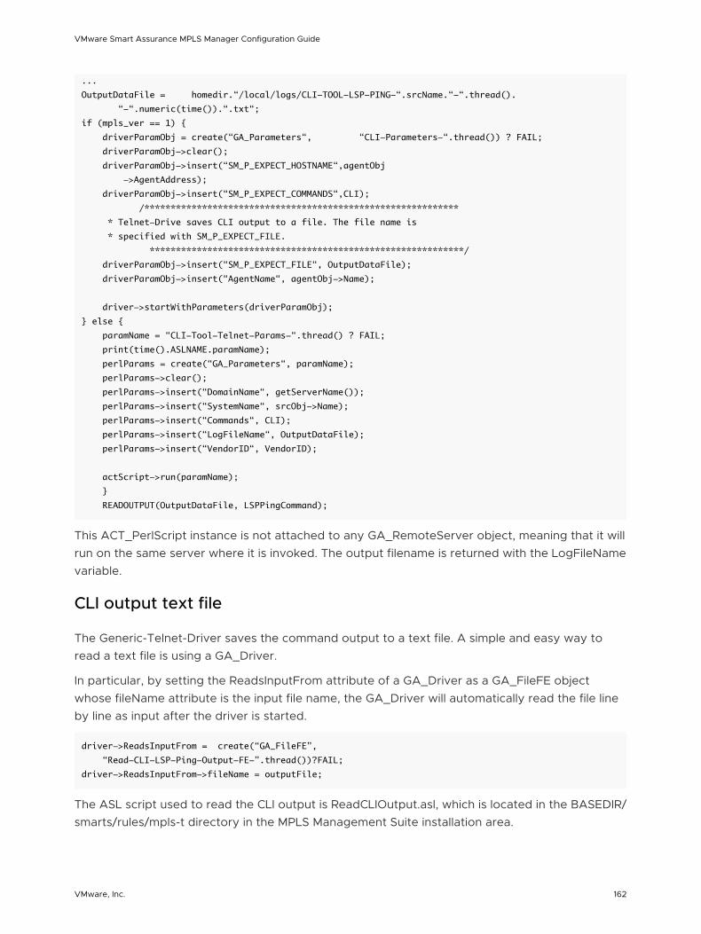
...
OutputDataFile = homedir.“/local/logs/CLI-TOOL-LSP-PING-“.srcName.“-“.thread().
“-“.numeric(time()).“.txt“;
if (mpls_ver == 1) {
driverParamObj = create(“GA_Parameters“, “CLI-Parameters-“.thread()) ? FAIL;
driverParamObj->clear();
driverParamObj->insert(“SM_P_EXPECT_HOSTNAME“,agentObj
->AgentAddress);
driverParamObj->insert(“SM_P_EXPECT_COMMANDS“,CLI);
/************************************************************
* Telnet-Drive saves CLI output to a file. The file name is
* specified with SM_P_EXPECT_FILE.
************************************************************/
driverParamObj->insert(“SM_P_EXPECT_FILE“, OutputDataFile);
driverParamObj->insert(“AgentName“, agentObj->Name);
driver->startWithParameters(driverParamObj);
} else {
paramName = “CLI-Tool-Telnet-Params-“.thread() ? FAIL;
print(time().ASLNAME.paramName);
perlParams = create(“GA_Parameters“, paramName);
perlParams->clear();
perlParams->insert(“DomainName“, getServerName());
perlParams->insert(“SystemName“, srcObj->Name);
perlParams->insert(“Commands“, CLI);
perlParams->insert(“LogFileName“, OutputDataFile);
perlParams->insert(“VendorID“, VendorID);
actScript->run(paramName);
}
READOUTPUT(OutputDataFile, LSPPingCommand);
This ACT_PerlScript instance is not attached to any GA_RemoteServer object, meaning that it will run on the same server where it is invoked. The output filename is returned with the LogFileName variable.
CLI output text file
The Generic-Telnet-Driver saves the command output to a text file. A simple and easy way to read a text file is using a GA_Driver.
In particular, by setting the ReadsInputFrom attribute of a GA_Driver as a GA_FileFE object whose fileName attribute is the input file name, the GA_Driver will automatically read the file line by line as input after the driver is started.
driver->ReadsInputFrom = create(“GA_FileFE”,
“Read-CLI-LSP-Ping-Output-FE-”.thread())?FAIL;
driver->ReadsInputFrom->fileName = outputFile;
The ASL script used to read the CLI output is ReadCLIOutput.asl, which is located in the BASEDIR/smarts/rules/mpls-t directory in the MPLS Management Suite installation area.
VMware Smart Assurance MPLS Manager Configuration Guide
VMware, Inc. 162
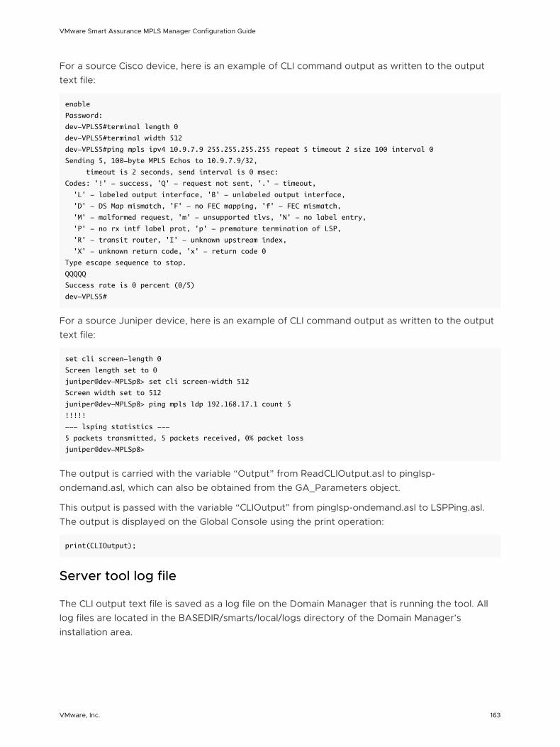
For a source Cisco device, here is an example of CLI command output as written to the output text file:
enable
Password:
dev-VPLS5#terminal length 0
dev-VPLS5#terminal width 512
dev-VPLS5#ping mpls ipv4 10.9.7.9 255.255.255.255 repeat 5 timeout 2 size 100 interval 0
Sending 5, 100-byte MPLS Echos to 10.9.7.9/32,
timeout is 2 seconds, send interval is 0 msec:
Codes: '!' - success, 'Q' - request not sent, '.' - timeout,
'L' - labeled output interface, 'B' - unlabeled output interface,
'D' - DS Map mismatch, 'F' - no FEC mapping, 'f' - FEC mismatch,
'M' - malformed request, 'm' - unsupported tlvs, 'N' - no label entry,
'P' - no rx intf label prot, 'p' - premature termination of LSP,
'R' - transit router, 'I' - unknown upstream index,
'X' - unknown return code, 'x' - return code 0
Type escape sequence to stop.
QQQQQ
Success rate is 0 percent (0/5)
dev-VPLS5#
For a source Juniper device, here is an example of CLI command output as written to the output text file:
set cli screen-length 0
Screen length set to 0
juniper@dev-MPLSp8> set cli screen-width 512
Screen width set to 512
juniper@dev-MPLSp8> ping mpls ldp 192.168.17.1 count 5
!!!!!
--- lsping statistics ---
5 packets transmitted, 5 packets received, 0% packet loss
juniper@dev-MPLSp8>
The output is carried with the variable “Output” from ReadCLIOutput.asl to pinglsp-ondemand.asl, which can also be obtained from the GA_Parameters object.
This output is passed with the variable “CLIOutput” from pinglsp-ondemand.asl to LSPPing.asl. The output is displayed on the Global Console using the print operation:
print(CLIOutput);
Server tool log file
The CLI output text file is saved as a log file on the Domain Manager that is running the tool. All log files are located in the BASEDIR/smarts/local/logs directory of the Domain Manager’s installation area.
VMware Smart Assurance MPLS Manager Configuration Guide
VMware, Inc. 163
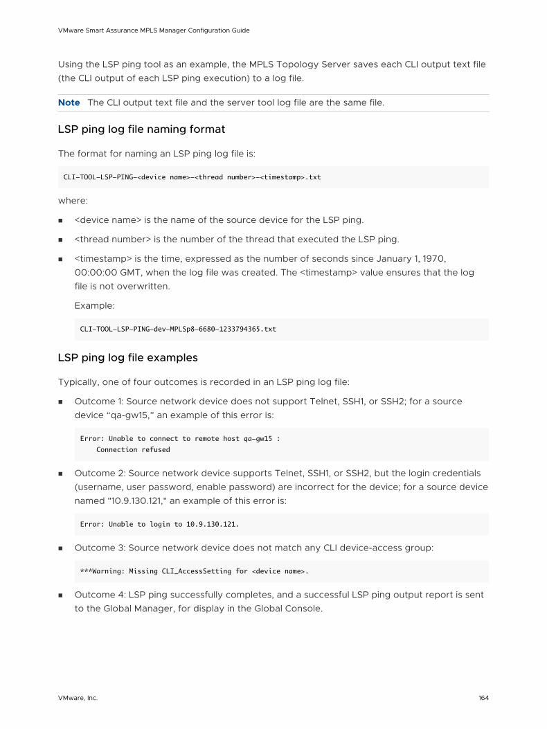
Using the LSP ping tool as an example, the MPLS Topology Server saves each CLI output text file (the CLI output of each LSP ping execution) to a log file.
Note The CLI output text file and the server tool log file are the same file.
LSP ping log file naming format
The format for naming an LSP ping log file is:
CLI-TOOL-LSP-PING-<device name>-<thread number>-<timestamp>.txt
where:
n <device name> is the name of the source device for the LSP ping.
n <thread number> is the number of the thread that executed the LSP ping.
n <timestamp> is the time, expressed as the number of seconds since January 1, 1970, 00:00:00 GMT, when the log file was created. The <timestamp> value ensures that the log file is not overwritten.
Example:
CLI-TOOL-LSP-PING-dev-MPLSp8-6680-1233794365.txt
LSP ping log file examples
Typically, one of four outcomes is recorded in an LSP ping log file:
n Outcome 1: Source network device does not support Telnet, SSH1, or SSH2; for a source device “qa-gw15,” an example of this error is:
Error: Unable to connect to remote host qa-gw15 :
Connection refused
n Outcome 2: Source network device supports Telnet, SSH1, or SSH2, but the login credentials (username, user password, enable password) are incorrect for the device; for a source device named "10.9.130.121," an example of this error is:
Error: Unable to login to 10.9.130.121.
n Outcome 3: Source network device does not match any CLI device-access group:
***Warning: Missing CLI_AccessSetting for <device name>.
n Outcome 4: LSP ping successfully completes, and a successful LSP ping output report is sent to the Global Manager, for display in the Global Console.
VMware Smart Assurance MPLS Manager Configuration Guide
VMware, Inc. 164
Wildcard Patterns 11This chapter includes the following topics:
n Types of wildcard patterns
Types of wildcard patterns
A wildcard pattern is a series of characters that are matched against incoming character strings. You can use these patterns when you define pattern matching criteria.
Matching is done strictly from left to right, one character or basic wildcard pattern at a time. Basic wildcard patterns are defined in Basic wildcard patterns. Characters that are not part of match constructs match themselves. The pattern and the incoming string must match completely. For example, the pattern abcd does not match the input abcde or abc.
A compound wildcard pattern consists of one or more basic wildcard patterns that are separated by ampersand (&) or tilde (~) characters. A compound wildcard pattern is matched by attempting to match each of its component basic wildcard patterns against the entire input string. Compound wildcard patterns are listed in Compound wildcard patterns.
If the first character of a compound wildcard pattern is an ampersand (&) or tilde (~) character, the compound is interpreted as if an asterisk (*) appeared at the beginning of the pattern. For example, the pattern ~*[0-9]* matches any string that does not contain any digits. A trailing instance of an ampersand character (&) can only match the empty string. A trailing instance of a tilde character (~) can be read as “except for the empty string.”
Note Spaces are interpreted as characters and are subject to matching even if they are adjacent to operators like “&”.
Table 11-1. Basic wildcard patterns
Character Description
? Matches any single character.
For example, server?.example.com matches server3.example.com and serverB.example.com, but not server10.example.com.
* Matches an arbitrary string of characters. The string can be empty.
For example, server*.example.com matches server-ny.example.com and server.example.com (an empty match).
VMware, Inc. 165
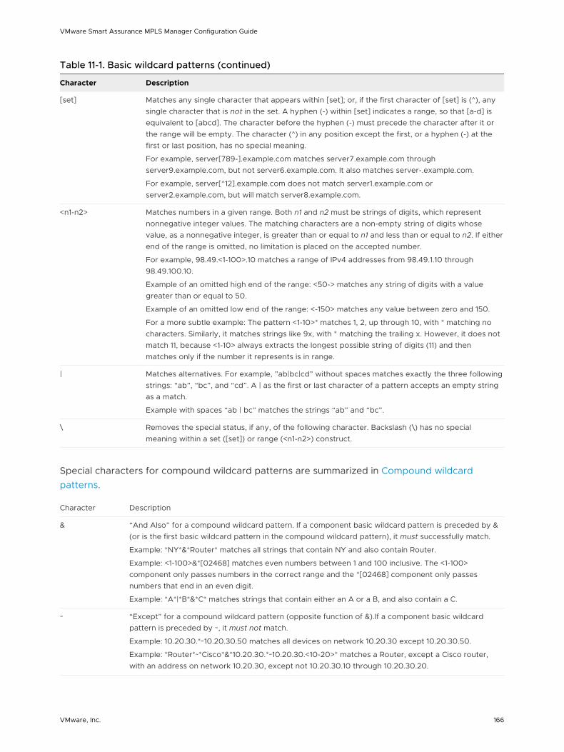
Table 11-1. Basic wildcard patterns (continued)
Character Description
[set] Matches any single character that appears within [set]; or, if the first character of [set] is (^), any single character that is not in the set. A hyphen (-) within [set] indicates a range, so that [a-d] is equivalent to [abcd]. The character before the hyphen (-) must precede the character after it or the range will be empty. The character (^) in any position except the first, or a hyphen (-) at the first or last position, has no special meaning.
For example, server[789-].example.com matches server7.example.com through server9.example.com, but not server6.example.com. It also matches server-.example.com.
For example, server[^12].example.com does not match server1.example.com or server2.example.com, but will match server8.example.com.
<n1-n2> Matches numbers in a given range. Both n1 and n2 must be strings of digits, which represent nonnegative integer values. The matching characters are a non-empty string of digits whose value, as a nonnegative integer, is greater than or equal to n1 and less than or equal to n2. If either end of the range is omitted, no limitation is placed on the accepted number.
For example, 98.49.<1-100>.10 matches a range of IPv4 addresses from 98.49.1.10 through 98.49.100.10.
Example of an omitted high end of the range: <50-> matches any string of digits with a value greater than or equal to 50.
Example of an omitted low end of the range: <-150> matches any value between zero and 150.
For a more subtle example: The pattern <1-10>* matches 1, 2, up through 10, with * matching no characters. Similarly, it matches strings like 9x, with * matching the trailing x. However, it does not match 11, because <1-10> always extracts the longest possible string of digits (11) and then matches only if the number it represents is in range.
| Matches alternatives. For example, ”ab|bc|cd” without spaces matches exactly the three following strings: “ab”, “bc”, and “cd”. A | as the first or last character of a pattern accepts an empty string as a match.
Example with spaces “ab | bc” matches the strings “ab” and “bc”.
\ Removes the special status, if any, of the following character. Backslash (\) has no special meaning within a set ([set]) or range (<n1-n2>) construct.
Special characters for compound wildcard patterns are summarized in Compound wildcard patterns.
Character Description
& “And Also” for a compound wildcard pattern. If a component basic wildcard pattern is preceded by & (or is the first basic wildcard pattern in the compound wildcard pattern), it must successfully match.
Example: *NY*&*Router* matches all strings that contain NY and also contain Router.
Example: <1-100>&*[02468] matches even numbers between 1 and 100 inclusive. The <1-100> component only passes numbers in the correct range and the *[02468] component only passes numbers that end in an even digit.
Example: *A*|*B*&*C* matches strings that contain either an A or a B, and also contain a C.
~ “Except” for a compound wildcard pattern (opposite function of &).If a component basic wildcard pattern is preceded by ~, it must not match.
Example: 10.20.30.*~10.20.30.50 matches all devices on network 10.20.30 except 10.20.30.50.
Example: *Router*~*Cisco*&*10.20.30.*~10.20.30.<10-20>* matches a Router, except a Cisco router, with an address on network 10.20.30, except not 10.20.30.10 through 10.20.30.20.
VMware Smart Assurance MPLS Manager Configuration Guide
VMware, Inc. 166
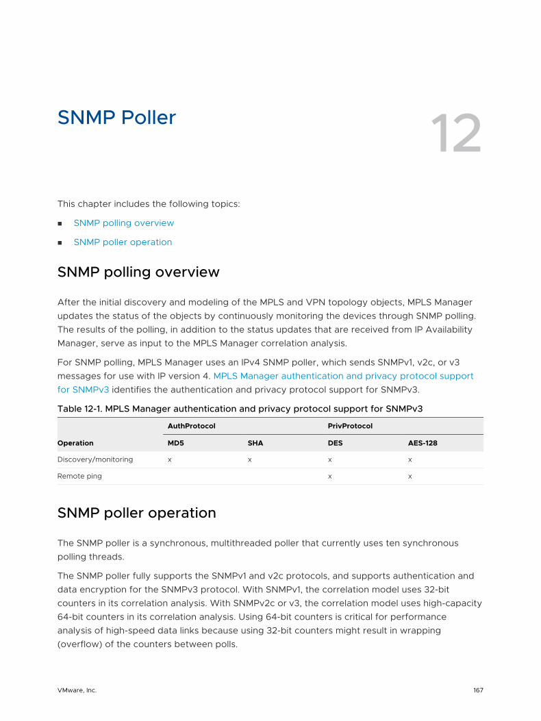
SNMP Poller 12This chapter includes the following topics:
n SNMP polling overview
n SNMP poller operation
SNMP polling overview
After the initial discovery and modeling of the MPLS and VPN topology objects, MPLS Manager updates the status of the objects by continuously monitoring the devices through SNMP polling. The results of the polling, in addition to the status updates that are received from IP Availability Manager, serve as input to the MPLS Manager correlation analysis.
For SNMP polling, MPLS Manager uses an IPv4 SNMP poller, which sends SNMPv1, v2c, or v3 messages for use with IP version 4. MPLS Manager authentication and privacy protocol support for SNMPv3 identifies the authentication and privacy protocol support for SNMPv3.
Table 12-1. MPLS Manager authentication and privacy protocol support for SNMPv3
Operation
AuthProtocol PrivProtocol
MD5 SHA DES AES-128
Discovery/monitoring x x x x
Remote ping x x
SNMP poller operation
The SNMP poller is a synchronous, multithreaded poller that currently uses ten synchronous polling threads.
The SNMP poller fully supports the SNMPv1 and v2c protocols, and supports authentication and data encryption for the SNMPv3 protocol. With SNMPv1, the correlation model uses 32-bit counters in its correlation analysis. With SNMPv2c or v3, the correlation model uses high-capacity 64-bit counters in its correlation analysis. Using 64-bit counters is critical for performance analysis of high-speed data links because using 32-bit counters might result in wrapping (overflow) of the counters between polls.
VMware, Inc. 167
Polling for devices with multiple IP addresses is supported because the SNMP poller supports multiple IP addresses for each SNMP agent. The SNMP poller automatically switches to an alternate IP address during failures, thereby ensuring the integrity of the MPLS Manager correlation analysis during an outage.
Just-in-time polling
The SNMP poller’s MIB variable poll list is driven by a Just-In-Time polling algorithm, which ensures that only those MIB variables needed for correlation are polled. For example, if a port monitored for performance data is disabled, or goes down, the SNMP poller automatically removes the relevant MIB variables from the poll list. If the port is re-enabled, or comes back up, the variables are automatically put back onto the MIB poll list.
Request-consolidation polling
Issuing a single SNMP GET request that requests 10 variables is more efficient than issuing 10 GET requests each requesting a single variable. The SNMP poller consolidates as many variables as possible into a single SNMP GET request. The consolidation is not restricted to variables from the same SNMP table. Polling consolidation continually adapts to changes in the MIB variable poll list.
Upon encountering a non-fatal error during polling consolidation, the SNMP poller responds differently to an SNMPv1 agent than to an SNMPv2c or v3 agent for the following reason: Where an SNMPv1 agent stops processing a request upon encountering an error, an SNMPv2c or v3 agent continues processing a request upon encountering an error. An SNMPv2c or v3 agent handles errors on a per-OID basis.
If a non-fatal error is encountered by an SNMPv1 agent during a GET request that is seeking multiple variables, the SNMP poller suspends the polling of the affected variable because continuing to poll that variable would require the resending of the remainder of the request after receiving the error. An example of an affected variable is one that has become unavailable due to a configuration change. Of course, the SNMP poller continues to poll the unaffected variables. This behavior enables the SNMP poller to operate efficiently with an SNMPv1 agent during unexpected changes to a device’s configuration.
In contrast, if a non-fatal error is encountered by an SNMPv2c or v3 agent during a GET request that is seeking multiple variables, the SNMP poller continues the polling of the affected variable as well as the unaffected variables.
VMware Smart Assurance MPLS Manager Configuration Guide
VMware, Inc. 168
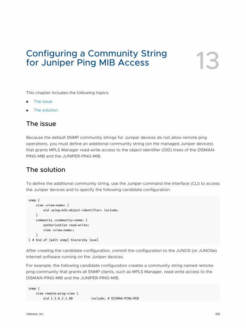
Configuring a Community String for Juniper Ping MIB Access 13This chapter includes the following topics:
n The issue
n The solution
The issue
Because the default SNMP community strings for Juniper devices do not allow remote ping operations, you must define an additional community string (on the managed Juniper devices) that grants MPLS Manager read-write access to the object identifier (OID) trees of the DISMAN-PING-MIB and the JUNIPER-PING-MIB.
The solution
To define the additional community string, use the Juniper command line interface (CLI) to access the Juniper devices and to specify the following candidate configuration:
snmp {
view <view-name> {
oid <ping-mib-object-identifier> include;
}
community <community-name> {
authorization read-write;
view <view-name>;
}
} # End of [edit snmp] hierarchy level
After creating the candidate configuration, commit the configuration to the JUNOS (or JUNOSe) Internet software running on the Juniper devices.
For example, the following candidate configuration creates a community string named remote-ping-community that grants all SNMP clients, such as MPLS Manager, read-write access to the DISMAN-PING-MIB and the JUNIPER-PING-MIB.
snmp {
view remote-ping-view {
oid 1.3.6.2.1.80 include; # DISMAN-PING-MIB
VMware, Inc. 169
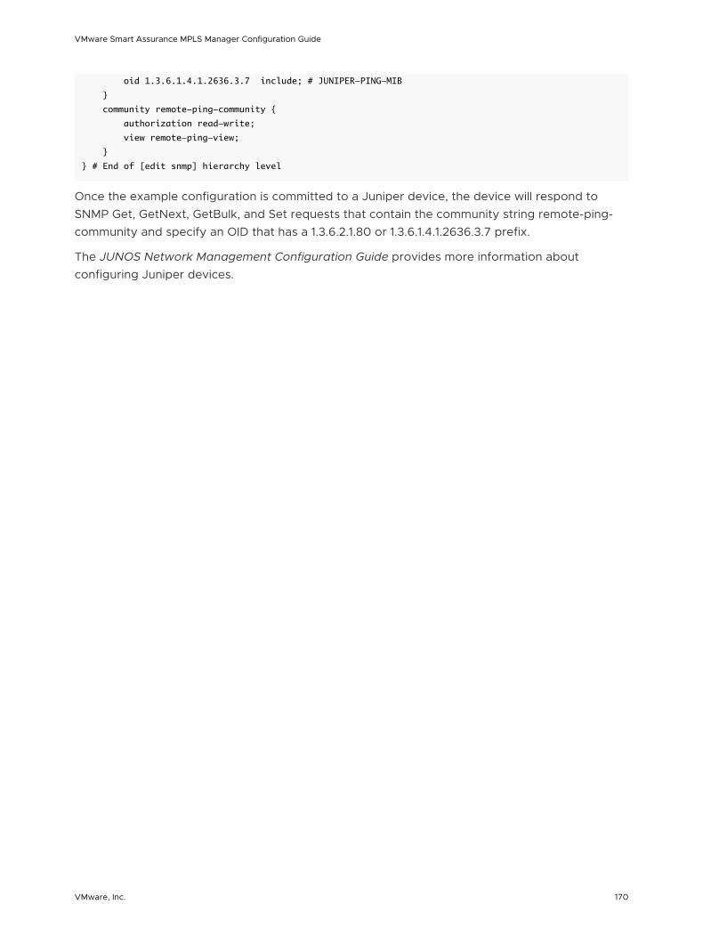
oid 1.3.6.1.4.1.2636.3.7 include; # JUNIPER-PING-MIB
}
community remote-ping-community {
authorization read-write;
view remote-ping-view;
}
} # End of [edit snmp] hierarchy level
Once the example configuration is committed to a Juniper device, the device will respond to SNMP Get, GetNext, GetBulk, and Set requests that contain the community string remote-ping-community and specify an OID that has a 1.3.6.2.1.80 or 1.3.6.1.4.1.2636.3.7 prefix.
The JUNOS Network Management Configuration Guide provides more information about configuring Juniper devices.
VMware Smart Assurance MPLS Manager Configuration Guide
VMware, Inc. 170


![[MPLS Configuration Guide] - D-Link Academyacademy.dlink.com/temp/exam_Issue/230/MPLS Configuration Guide… · MPLS Configuration Guide Multiprotocol Label Switching (MPLS) MPLS](https://img.dokumen.tips/doc/110x75/5a815ac47f8b9ada388cfeea/mpls-configuration-guide-d-link-configuration-guidempls-configuration-guide.jpg)