Embed Size (px)
Citation preview

VMware Smart Assurance IP Manager Deployment Guide
VMware Smart Assurance 10.1.2

You can find the most up-to-date technical documentation on the VMware website at:
https://docs.vmware.com/
VMware, Inc.3401 Hillview Ave.Palo Alto, CA 94304www.vmware.com
Copyright ©
2021 VMware, Inc. All rights reserved. Copyright and trademark information.
VMware Smart Assurance IP Manager Deployment Guide
VMware, Inc. 2

Contents
1 Preface 10Purpose 10
Audience 10
2 VMware Smart Assurance IP Manager installation directory 12
3 VMware Smart Assurance IP Manager products 13
4 Related documentation 14
5 VMware Smart Assurance IP Manager documentation 15
6 Conventions used in this document 16Typographical conventions 16
7 Your comments 18
8 Where to get help 19
9 Overview of the VMware Smart Assurance Deployment Process 20Deployment process 20
Phase 1: Designing the VMware Smart Assurance deployment 21
Phase 2: Installing and configuring the VMware Smart Assurance components 22
Phase 3: Validating the deployment 22
Phase 4: Tuning and maintaining the deployment 23
Before-you-begin checklist 23
10 Gathering Information for Designing 25Determine the organization’s requirements 25
Obtain network information 25
Obtain network diagrams 26
Naming conventions 26
Network priorities 27
Identify the types of equipment in the network 27
Determine requirements for installing software 28
Integrating existing software with VMware Smart Assurance software 28
Determine number of managed network devices 29
Refining the estimate for sizing an VMware Smart Assurance deployment 29
VMware, Inc. 3

Estimates based on ports and interfaces 30
Estimates based on routers and switches 30
Estimates based on devices (level 2/level 3) 31
Accounting for sub-interface monitoring 32
Accounting for network growth 32
Determine quantities of devices for licensing 33
Gather network security information 34
Other network features affecting deployment design 35
Architectural information checklist 35
11 Designing the VMware Smart AssuranceDeployment 38Document the deployment 38
Solution architecture diagram 38
Deployment build guide 39
Determine resources required to support the deployment 39
Determine memory requirements for network objects 39
Determine discovery processing requirements 40
Discovery CPU 41
Discovery bandwidth 42
Discovery threads 43
Determine polling processing requirements 44
Polling bandwidth 46
Partition networks 46
Multiple domains on a single platform 46
Add information to solution architecture diagram and deployment build guide 46
Locate Domain Managers and platforms 47
Consider security 48
Consider security and firewalls 48
Consider high availability configurations 49
Design for overlapping (duplicate) IP networks 49
Design acceptance tests 49
Solution architecture diagram checklist 49
12 Planning for Discovery 51Before you start 51
Discovery design considerations 51
Initial topology discovery 52
Using a comprehensive seed file 52
When to use autodiscovery 52
When not to use autodiscovery 53
Using autodiscovery during initial discovery 54
VMware Smart Assurance IP Manager Deployment Guide
VMware, Inc. 4

Subsequent topology discovery and maintenance 54
Adding new systems to an existing topology 55
Controlling autodiscovery with filters 56
Automating manual discovery 56
Discovery and security 56
Discovery and certified device types 57
Discovery and name resolution 57
Discovery and postprocessing customization 58
Discovery design checklist 59
13 Designing Polling and Thresholds 61Before you start 61
Polling and threshold design considerations 63
Polling and polling groups 63
Matching-criteria considerations 63
Polling timeout considerations 64
Network latency considerations 64
Thresholds and threshold groups 64
Polling and threshold checklist 65
14 Deploying Syslog Processing 67Syslog processing applications 67
Creating the syslog file 67
Processing the syslog file 68
Syslog processing checklist (optional) 69
15 Configuring SNMP Trap Integration 71Introduction to trap deployment 71
Scenario 1: Single Trap Adapter (receiver) associated with Adapter Platform (not for production use) 71
Scenario 2: Trap exploder forwards traps to a second trap receiver 72
To configure the trap exploder, edit the following files: 73
To configure the second trap receiver (associated with Adapter Platform) 73
Configuring the SNMP Trap Adapter to receive SNMPv3 traps 73
Configuring the seed file to load SNMPv3 credentials 74
Editing seed files 75
Encryption (Privacy) options supported in SNMPv3 seed file 77
Loading the seed file into the Local Credentials Database (LCD) 77
Managing seed file updates 78
Configuring trapd.conf (trap exploder and trap receiver) 78
Examples of forwarding entries 78
Trap exploder operation 79
VMware Smart Assurance IP Manager Deployment Guide
VMware, Inc. 5

Trap exploder’s translation and authentication of traps 79
Trap exploder’s handling of IPv6 traps 80
Adapter Platform trap receiver operation 81
Built-in IP Manager trap receiver operation 81
Configuration parameters in trapd.conf 82
Enabling multiple trap listening ports on the same host 85
Using SM_SITEMOD to edit copies of trapd.conf 85
16 Configuring SNMP Trap Notifier Adapter 87Introduction 87
VMware Smart Assurance product foundation components 89
IPv6 and IPv4 notifications support 89
SNMP Trap Notifier Adapter configuration file: trap-notify.conf 89
Destination settings 90
Suppression setting 90
Service Assurance notification subscription 91
IP Manager notification subscription 91
17 Designing for Administration of VMware Smart AssuranceUsers 95Who are the Global Console users? 95
Users and security 96
Password configurations 96
Designing user profiles 97
Designing notification lists 97
Restricting console operations 98
Designing consoles 98
Planning for tools and tool deployment 98
Administration Design Checklist 98
18 Deploying VMware Smart Assurance Components 100General installation/deployment guidelines 100
Allow access to MIBs in network devices 100
VMware Smart Assurance installation 100
Setting environment variables 101
Configure security 101
Use and guard your VMware Smart Assurance secret phrase 101
Deploy trap processing 102
Deploy VMware Smart Assurance user configurations 103
19 Validating Your Deployment (Acceptance Testing) 104Validation techniques 104
VMware Smart Assurance IP Manager Deployment Guide
VMware, Inc. 6

Initial validation 104
Validating discovery 104
Validating polling and events 105
Validating trap processing 105
Validating users and capabilities 105
20 Tuning Your Deployment to Improve Performance 107Performance tuning guidelines 107
Reviewing VMware Smart Assurance license metrics 107
Reviewing VMware Smart Assurance performance metrics 108
Codebook tasks 108
Duration of last discovery 109
Discovery postprocessing 110
Reconfiguration and saving the repository 110
ICMP processing statistics 111
SNMP processing statistics 112
Calculate SNMP polling thread utilization 113
Improving performance 114
Other tuning issues 114
Adjust performance thresholds to reduce inappropriate alarms 114
Use batching to improve trap processing performance 114
Filtering traps in trapd.conf 114
Global Console performance 115
Managing memory for large processes 115
21 Defining a CPU 117Using SPEC to define a CPU 117
22 Hardware Specifications 118Hardware models and parameter estimates 118
23 CPU Estimates for Single-threaded Tasks 119CPU estimates for single-threaded tasks 119
24 Managing Overlapping IP Networks 122Overview 122
IP management domains 124
Virtual IP interface support 124
Policy-based routing or source-routing support 125
IP tagging support 125
IP management domain configuration steps 125
VMware Smart Assurance IP Manager Deployment Guide
VMware, Inc. 7

Configuring virtual IP interfaces 126
Creating virtual IP interfaces to direct management traffic 128
Binding a Domain Manager to a virtual IP address 128
Configuring policy-based routing or source routing 128
Using a policy-based router to route management traffic 128
Using source routes to route management traffic 129
Creating an IP tag filter 130
Configuring SNMP trap forwarding 130
IP Management domain information consolidation 131
Consolidation by the Global Manager 131
25 Guidelines and Best Practices for Running Smart Assurance on VMware 132Overview 132
Test methodology 134
Software 134
Hardware 134
Scenarios 134
VMware configuration guidelines 135
Hardware configurations 135
VMware Tools 135
VMware network adapter 136
VMware virtual switch 136
CPU allocation 138
Hyperthreading 138
Memory allocation 139
VMware Distributed Resource Scheduler 139
VMware High Availability 140
VMware Fault Tolerance 140
Ensure adequate allocation of CPU and memory resources 140
Monitor CPU and memory performance 141
Tab pages 141
esxtop data 141
Test results 142
VMware deployment checklist 143
26 Design and Deployment Checklists 144Before-you-begin checklist 144
Architectural information checklist 145
Solution architecture diagram checklist 147
Discovery design checklist 148
Polling and threshold checklist 150
VMware Smart Assurance IP Manager Deployment Guide
VMware, Inc. 8

Syslog processing checklist (optional) 151
VMWare deployment checklist (optional) 152
VMware Smart Assurance IP Manager Deployment Guide
VMware, Inc. 9

Preface 1As part of an effort to improve its product lines, VMware periodically releases revisions of its software and hardware. Therefore, some functions described in this document might not be supported by all versions of the software or hardware currently in use. The product release notes provide the most up-to-date information on product features.
Contact your VMware representative if a product does not function properly or does not function as described in this document.
Note This document was accurate at publication time. Go to VMware Online Support docs.vmware.com to ensure that you are using the latest version of this document.
This chapter includes the following topics:
n Purpose
n Audience
Purpose
This document is part of the VMware Smart Assurance IP Manager documentation set. It describes how to deploy the IP Manager components and the Service Assurance Manager components in an VMware Smart Assurance deployment.
Audience
This document is intended for the following audiences:
n Systems engineers who design VMware Smart Assurance deployments
n Network and system administrators who aid in the design of VMware Smart Assurance deployments and then maintain the deployments
n Integrators and network consultants who aid in the design of VMware Smart Assurance deployments and then install, validate, and tune the deployments
n VMware Professional Services personnel who design, install, validate, and tune VMware Smart Assurance deployments
VMware, Inc. 10

n VMware Support personnel who respond to inquiries, problems, and issues that arise during VMware Smart Assurance deployments
VMware Smart Assurance IP Manager Deployment Guide
VMware, Inc. 11

VMware Smart Assurance IP Manager installation directory 2In this document, the term BASEDIR represents the location where VMware Smart Assurance software is installed.
n For UNIX, this location is: /opt/InCharge/<productsuite>.
On UNIX operating systems, VMware Smart Assurance IP Availability Manager is, by default, installed to: /opt/InCharge/IP/smarts.
Optionally, you can specify the root of BASEDIR to be something different, but you cannot change the <productsuite> location under the root directory. The VMware Smart Assurance System Administration Guide provides more information about the directory structure of VMware Smart Assurance software.
VMware, Inc. 12

VMware Smart Assurance IP Manager products 3The VMware Smart Assurance IP Manager includes the following products:
n VMware Smart Assurance IP Availability Manager
n VMware Smart Assurance IP Performance Manager
n VMware Smart Assurance IP Availability Manager Extension for NAS
VMware, Inc. 13

Related documentation 4Readers of this guide might find the following related documentation helpful.
Note These documents are updated periodically. Electronic versions of the updated manuals are available on VMware Online Support at: docs.vmware.com
n VMware Smart Assurance System Administration Guide
n VMware Smart Assurance Common Information Model (ICIM) 1.11 Reference for Non-Service Assurance Manager Products
n VMware Smart Assurance Common Information Model (ICIM) Reference for Service Assurance Manager
n Smarts Foundation EMC Data Access API (EDAA) Programmer Guide
n VMware Smart Assurance ASL Reference Guide
n VMware Smart Assurance Perl Reference Guide
n VMware Smart Assurance MODEL Reference Guide
n VMware Smart Assurance Dynamic Modeling Tutorial
VMware, Inc. 14

VMware Smart Assurance IP Manager documentation 5The following VMware Smart Assurance documents are relevant to users of the IP Management product suite:
n VMware Smart Assurance IP Manager Release Notes
n VMware Smart Assurance Third-Party Copyright Read Me for SAM, IP, ESM, and MPLS Managers
n VMware Smart Assurance Installation Guide for SAM, IP, ESM, MPLS, and NPM Managers
n VMware Smart Assurance IP Manager Deployment Guide
n VMware Smart Assurance IP Manager Concepts Guide
n VMware Smart Assurance IP Manager User Guide
n VMware Smart Assurance IP Manager Reference Guide
n VMware Smart Assurance IP Manager Troubleshooting Guide
n VMware Smart Assurance IP Manager Certification Matrix
n VMware Smart Assurance Topology Split Manager User Guide
VMware, Inc. 15

Conventions used in this document 6VMware uses the following conventions for special notices:
Note NOTICE is used to address practices not related to personal injury.
A note presents information that is important, but not hazard-related.
An important notice contains information essential to software or hardware operation.
This chapter includes the following topics:
n Typographical conventions
Typographical conventions
VMware uses the following type style conventions in this document:
Bold Use for names of interface elements
Italic Use for full titles of publications referenced in text
MonospaceUse for:
n System output, such as an error message or script
n System code
n Pathnames, filenames, prompts, and syntax
n Commands and options
Monospace italic
Use for variables.
Monospace bold
Use for user input.
[ ] Square brackets enclose optional values
| Vertical bar indicates alternate selections — the bar means “or”
VMware, Inc. 16

{ } Braces enclose content that the user must specify, such as x or y or z
... Ellipses indicate nonessential information omitted from the example
VMware Smart Assurance IP Manager Deployment Guide
VMware, Inc. 17

Your comments 7Your suggestions will help us continue to improve the accuracy, organization, and overall quality of the user publications. Provide your feedback of this document to:
docs.vmware.com
VMware, Inc. 18

Where to get help 8VMware support, product, and licensing information can be obtained as follows:
Product information
For documentation, release notes, software updates, or information about VMware products, go to VMware Online Support at:
docs.vmware.com
Technical support
Go to VMware Online Support. You will see several options for contacting VMware Technical Support. Note that to open a service request, you must have a valid support agreement. Contact your VMware sales representative for details about obtaining a valid support agreement or with questions about your account.
VMware, Inc. 19

Overview of the VMware Smart Assurance Deployment Process 9This chapter consists of the following sections:
n Deployment process
n Before-you-begin checklist
This chapter includes the following topics:
n Deployment process
n Before-you-begin checklist
Deployment process
The VMware Smart Assurance deployment process shows that the VMware Smart Assurance deployment process is divided into four distinct phases:
n Phase 1: Designing the VMware Smart Assurance deployment
n Phase 2: Installing and configuring the VMware Smart Assurance components
n Phase 3: Validating the VMware Smart Assurance deployment
n Phase 4: Tuning and maintaining the VMware Smart Assurance deployment to improve performance
During each phase of deployment, you must document all aspects of the deployment that could be required to re-create, troubleshoot, and reconfigure the installation.
VMware, Inc. 20

Figure 9-1. The VMware Smart Assurance deployment process
Phase 1: Designing the VMware Smart Assurance deployment
Designing an VMware Smart Assurance deployment consists of gathering the necessary information and then using the information to develop a plan for the VMware Smart Assurance deployment.
Gathering the information is a process that involves both the designer and the network administrators. Network administrators must provide details of their network’s OSI model Layer 2 and Layer 3 infrastructure:
n List the quantities and types of devices such as routers, switches, hubs, and bridges and their ports and interfaces. Include plans for adding or removing equipment during the time period that the deployment design will cover.
n Provide IP addresses for use in discovery, including seed systems and filtering.
n Describe network geography, including locations of Network Operations Centers (NOCs) and equipment.
n Specify LAN and link speeds throughout the network and their relationship to the network geography.
This information is then applied, using sizing guidelines, to develop a deployment design that will properly support the network. The design should also account for projected growth of the network.
The design is detailed in a solution architecture diagram and a deployment build guide. In their preliminary stages, the diagram and guide could be used in the answer to an organization’s Request for Proposal (RFP) or Request for Quote (RFQ).
Once a deployment is contracted, the information in the solution architecture diagram can be refined and verified through meetings with network administrators.
Design is covered in the following chapters:
n Chapter 10 Gathering Information for Designing (normally performed by systems engineers)
VMware Smart Assurance IP Manager Deployment Guide
VMware, Inc. 21

n Chapter 11 Designing the VMware Smart AssuranceDeployment (normally performed by systems engineers and either VMware Professional Services or a partner)
n Chapter 12 Planning for Discovery (normally performed by VMware Professional Services or a partner)
n Chapter 13 Designing Polling and Thresholds (normally performed by VMware Professional Services or a partner)
n Chapter 14 Deploying Syslog Processing (optionally performed by VMware Professional Services or a partner)
n Chapter 17 Designing for Administration of VMware Smart AssuranceUsers (optionally performed by VMware Professional Services or a partner)
Phase 2: Installing and configuring the VMware Smart Assurance components
After the design is complete and has been reviewed by VMware Professional Services or an appropriately certified VMware partner, the next phase is installing and configuring components.
With any deployment, installation and configuration of VMware Smart Assurance components are usually performed in stages. Each installed and configured segment is validated individually as described in the next phase of the deployment process. This phased approach eases troubleshooting.
Many organizations have specific procedural requirements that must be met before and during installation of new software products in their production environments. These requirements might include lab installations with performance validations and preproduction deployments. Lab configurations usually require the use of a testbed that is configured and equipped similarly to the production environment. Acceptance tests may be performed before the deployment to the production environment. After the production deployment, the lab or testbed may be used to test upgrades and, if required, patches.
Though this guide cannot cover organization-specific requirements, it does provide guidelines that might aid you in responding to these conditions.
Installing and configuring an VMware Smart Assurance deployment is covered in Chapter 18 Deploying VMware Smart Assurance Components The deployment information, including software locations and all configuration choices should be recorded in the deployment build guide. Normally, this phase is performed by the purchaser of the VMware Smart Assurance deployment and either VMware Professional Services or a partner.
Phase 3: Validating the deployment
Validating the deployment ensures that all installed components are operational and able to communicate with each other as required, and that the appropriate components can properly discover and poll the network.
VMware Smart Assurance IP Manager Deployment Guide
VMware, Inc. 22

Usually logical segments are installed and validated to ease troubleshooting. Once all individual segments are installed and validated, the complete deployment must be validated from end to end. Included in this overall validation could be acceptance tests that demonstrate the functionality of the installation. Criteria for acceptance tests should be defined during the design phase. The execution of these acceptance tests and the results are then included in an installation or build report.
Validating the components in an VMware Smart Assurance deployment is covered in Chapter 19 Validating Your Deployment (Acceptance Testing) Normally, this phase is performed by the purchaser of the VMware Smart Assurance deployment and either VMware Professional Services or a partner.
Phase 4: Tuning and maintaining the deployment
Once the components are deployed and validated, you must ensure that the VMware Smart Assurance deployment is operating at an optimal level. Tuning is the process of adjusting the configuration to improve performance. Note that this initial tuning process does not include rules writing or related maintenance: VMware Smart Assurance software does not require this type of maintenance.
This process can only be performed after all components are installed and validated to avoid inaccurate tuning.
The process of tuning an VMware Smart Assurance deployment is covered in Chapter 20 Tuning Your Deployment to Improve Performance Normally, this phase is initially performed by either VMware Professional Services or a partner and the knowledge is transferred to the purchasing organization’s staff. As the network grows and changes, the organization’s staff will take on the task of tuning the VMware Smart Assurance deployment to deal with the network changes. If the network changes are extensive, the original design might no longer be sufficient and redesigning the deployment might be required.
Before-you-begin checklist
Before you begin an VMware Smart Assurance deployment, you must meet the requirements described in Before-you-begin checklist. Each chapter in this guide includes a checklist. For ease of use, the checklists are all grouped together in Chapter 26 Design and Deployment Checklists
VMware Smart Assurance IP Manager Deployment Guide
VMware, Inc. 23

Table 9-1. Before-you-begin checklist
Complete Requirement Description
Possess an understanding of the VMware Smart Assurance architecture and capabilities.
At a minimum, you must understand the concepts and VMware Smart Assurance architecture described in the following documents:
n VMware Smart Assurance IP Manager Concepts Guide
n VMware Smart Assurance IP Manager User Guide
n VMware Smart Assurance IP Manager Reference Guide
n VMware Smart Assurance Service Assurance Manager Configuration Guide
n VMware Smart Assurance Service Assurance Manager Introduction
n VMware Smart Assurance Service Assurance Manager Adapter Platform User Guide
n VMware Smart Assurance System Administration Guide
n VMware Smart Assurance Installation Guide for SAM, IP, ESM, MPLS, and NPM Managers that accompanied your software product suite
To improve your understanding, attend VMware Smart Assurance training courses. Typically, deployment requires the knowledge equivalent to what is provided in the training courses on:
n VMware Smart Assurance IP Manager
n VMware Smart Assurance Service Assurance Manager (Global Manager)
n VMware Smart Assurance Service Assurance Manager Adapter Platform (Adapter Platform)
Obtain contact information for the deployment team.
The contact list should include titles, responsibilities, and contact methods for all team members.
Get nondisclosure requirements and negotiate an agreement.
Be aware of the requirements of the non-disclosure agreements that are in place for the deployment.
Develop schedules and set milestones for early deliverable.
Scheduling a software deployment varies based on the size and scope of the deployment and the organization’s requirements. Typical milestones might include:
n Initial project meeting to define the deployment scope
n Purchase of VMware Smart Assurance software
n Project development begins
n Installation in test environment complete
n Testing complete
n Installation in production environment complete
n VMware Smart Assurance deployment goes live
Additional information on scheduling is beyond the scope of this guide.
VMware Smart Assurance IP Manager Deployment Guide
VMware, Inc. 24

Gathering Information for Designing 10This chapter includes the following topics:
n Determine the organization’s requirements
n Obtain network information
n Determine number of managed network devices
n Gather network security information
n Other network features affecting deployment design
n Architectural information checklist
Determine the organization’s requirements
The design of an VMware Smart Assurance deployment must support an organization’s needs. Most Requests for Information (RFIs), Requests for Proposal (RFPs), or Requests for Quote (RFQs) begin with a description of the overall organization and its vertical market. Understanding the organization and its market can aid in making design choices. Typical vertical markets are listed in Typical vertical markets.
Table 10-1. Typical vertical markets
Examples of vertical markets
Communications
E-Business
Education
Financial
General Business
Government/Defense
Health Care
Hosting Service Provider
Network Outsourcers
Retail
Transportation
Wireless
Use an understanding of the business expectations in a vertical market to ensure a successful design. For example, each industry varies in the amount of downtime it can tolerate. As a general rule, financial organizations tolerate less downtime than organizations in the education vertical market. This can guide your design of polling and of escalation.
Obtain network information
VMware, Inc. 25

Gather information that indicates the size of the network and how it is utilized to accomplish an organization’s goals. A primary source for some of this information is an organization’s RFI, RFP, or RFQ for the VMware Smart Assurance deployment. The RFQ will normally contain details about a network’s size and structure and deployment needs. Other sources of information include network diagrams and discussions with network administrators.
Obtain network diagrams
#unique_31/unique_31_Connect_42__IP_DEPLOY_INFO_GATHER_80277 shows a typical network diagram. To aid in design, the network diagram should include the physical geography of the network including locations for the following:
n Network Operations Center (NOC) and LANs
n All routing, bridging, and switching devices
n Firewalls
n Lower speed WAN links such as T1 links
n Higher speed network technologies such as FDDI and Gigabit Ethernet
Important IP addresses and address ranges should be listed on the diagram. Device names and device naming conventions should also be included.
Naming conventions
Device, interface, and port naming conventions are vitally important when adding customized processing to the deployment. Writing scripts to perform processing such as discovery postprocessing or advanced trap integration might only be practical in networks with naming conventions.
VMware Smart Assurance IP Manager Deployment Guide
VMware, Inc. 26
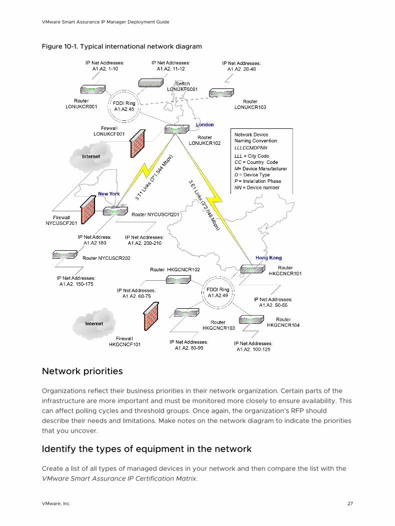
Figure 10-1. Typical international network diagram
Network priorities
Organizations reflect their business priorities in their network organization. Certain parts of the infrastructure are more important and must be monitored more closely to ensure availability. This can affect polling cycles and threshold groups. Once again, the organization’s RFP should describe their needs and limitations. Make notes on the network diagram to indicate the priorities that you uncover.
Identify the types of equipment in the network
Create a list of all types of managed devices in your network and then compare the list with the VMware Smart Assurance IP Certification Matrix.
VMware Smart Assurance IP Manager Deployment Guide
VMware, Inc. 27

Any SNMP-capable device that is not yet certified by VMware, Inc. will be discovered and monitored by the IP Manager by using generic SNMP MIB II instrumentation: More specific instrumentation will not be available until the device is certified. Many uncertified devices can be field certified or, to provide the highest level of compatibility, certified in VMware, Inc. labs.
To certify a device, VMware, Inc. requires the following information:
n A MIB walk of the uncertified device using the VMware Smart Assurance IP Manager utility, sm_snmpwalk.
n Device containment information such as the IP addresses, number of cards, ports, and interfaces.
n A diagram showing how the device is connected to other devices in your network.
n MIB walks of all connected devices using sm_snmpwalk.
Other information specifically related to the use of the uncertified device in your network might also be required.
VMware, Inc. periodically releases Service Packs for the VMware Smart Assurance IP Manager that provide certifications of new devices. The device certifications are intended to be as extensive as possible, but they might be prioritized to meet the needs of the majority of VMware Smart Assurance deployments.
Determine requirements for installing software
Most organizations define some criteria for installing new software on their network. At a minimum, this might include software testing requirements.
In addition to responding to these requirements, plan on using a staging area before deploying. By staging the deployment, you can maintain a “clean” software distribution that does not include unwanted files, changes, and logs.
Integrating existing software with VMware Smart Assurance software
Integrating third-party software products with VMware Smart Assurance software requires the use of VMware Smart Assurance Adapters. Most integrations do one of the following:
n Exchange information. Determine the exact type of information (topology or events) that must be exchanged with any third-party software products.
n Allow access to the third-party software from the Global Console. Some adapters provide this capability as the Server Tools functionality.
VMware, Inc. has developed many adapters that might already support the integration requirements of your deployment. Itemize the integration requirements so that the suitability of existing VMware Smart Assurance Adapters can be assessed by VMware Professional Services. This guide covers only the integration capabilities provided by the Syslog Adapter and the SNMP Trap Adapter (Receiver).
VMware Smart Assurance IP Manager Deployment Guide
VMware, Inc. 28

There are also extensive third-party software integration capabilities supported by other VMware Smart Assurance Adapters.
Determine number of managed network devices
For the following two purposes, determine the number of network adapters and devices that will be managed by the IP Manager in your VMware Smart Assurance deployment:
n The number of ports and interfaces is vitally important for accurately sizing the VMware Smart Assurance deployment. Sizing determines the number of Domain Managers to install and the required hardware configuration for the platforms where these servers will be installed.
n The number of devices is needed for volume licensing. The discovery process will halt if the number of discovered devices or network adapters exceeds the licensed quantity.
In most cases, an organization’s RFP or PFQ will estimate these quantities. This is the most common method of determining network devices: use the numbers from the RFP or RFQ as a starting point, and then improve the accuracy of those numbers by using discretion and by consulting the network administrators and other knowledgable personnel.
Refining the estimate for sizing an VMware Smart Assurance deployment
The network size determines the time it takes to complete discovery, the memory required, and the server hardware that should be selected to support Domain Managers. Estimates of network size from network administrators are usually based on one of the following quantities:
n Quantity of ports and interfaces
n Quantity of routers and switches
n Quantity of total devices
n Quantity of managed hosts
Ultimately, the most important quantities for sizing the server hardware in a deployment are the total number of ports and interfaces and the number of the total that managed. All ports are discovered using SNMP and ICMP. Managed ports and interfaces are then monitored using SNMP and ICMP to determine status and connectivity.
After numerous deployments, VMware, Inc. has developed ratios that help estimate the number of managed ports and interfaces with a high degree of accuracy. These ratios provide conservative estimates, which are especially important in large and very large networks. Being conservative is imperative, because VMware, Inc. has determined that even in well-managed large networks, administrators can underestimate the number of ports and interfaces by 30 percent or more. Always use the multipliers in conjunction with validation, discretion, and discussions with network administrators to improve the accuracy of the estimates.
VMware Smart Assurance IP Manager Deployment Guide
VMware, Inc. 29

Estimates based on ports and interfaces
If the network includes virtual routers, the count must include their interfaces in addition to the physical ports and interfaces. A virtual router is a software emulation of a router implemented within a physical router or switch.
Calculate the estimated number of managed ports and interfaces using the ratios of 90 percent managed for interfaces and 5 percent managed for ports:
Estimated number of managed ports and interfaces = 90 percent interfaces + 5 percent ports
For example, if the network has 2,300 interfaces and 18,000 ports, then calculate the managed ports and interfaces as follows:
Estimated number of managed ports and interfaces
= 90 percent interfaces + 5 percent ports
= ((90/100) * 2,300) + ((5/100) * 18,000)
= 2,070 + 900
= 2,970
All values that were less than one were rounded up in these calculations.
Estimates based on routers and switches
When the number of ports and interfaces is not available, the next best method is to use the number of routers and switches to make an estimate:
n Obtain the total number of routers and the total number of switches in the network. Include virtual routers in this count of physical systems if they are used in the network. VMware, Inc. has developed two multipliers to represent the typical number of ports and interfaces for these devices: 25 interfaces per router and 60 ports per switch. These values are typical in most deployments:
Total ports = 60 * switches
n
Total interfaces = 25 * routers
n Using the total ports and total interfaces, estimate the number of managed ports and interfaces. Use the managed ratios for ports (5 percent) and interfaces (90 percent) to calculate managed ports and interfaces:
Managed ports = 5 percent total ports
n
VMware Smart Assurance IP Manager Deployment Guide
VMware, Inc. 30

Managed interfaces = 90 percent total interfaces
n Add 30 percent to the estimate of managed ports and interfaces for uncertainty:
Estimated managed ports and interfaces
= (managed ports + managed interfaces) + 30 percent
n For example, if a network has 95 routers and 305 switches, the estimate for the number of managed ports and interfaces is calculated as follows:
Total ports = 60 * switches
= 60 * 305
= 18,300
n
Managed ports = 5 percent total ports
= (5/100) * 18,300
= 915
n
Total interfaces = 25 * routers
= 25 * 95
= 2,375
n
Managed interfaces = 90 percent total interfaces
= (90/100) * 2,375
= 2,138
n
Estimated managed ports and interfaces
= (managed ports + managed interfaces)+ 30 percent
= (915 + 2,138) + 30 percent
= 3,053 + ((30/100) * 3,053)
= 3,053 + 916
= 3,969
All values that were less than one were rounded up in these calculations.
Estimates based on devices (level 2/level 3)
VMware Smart Assurance IP Manager Deployment Guide
VMware, Inc. 31

The least accurate method for estimating the size of a deployment uses only the total of level 2 and level 3 devices:
n Use the total of devices, including virtual routers, to estimate the number of ports and interfaces in the network. VMware, Inc. has developed the multiplier of 50 to represent the typical number of ports and interfaces per device. This multiplier assumes a split of about 30 percent routers and 70 percent switches in the network:
Total ports and interfaces = 50 * devices
n Using total number of ports and interfaces, estimate the number of managed ports and interfaces. Assume that 35 percent of the total ports and interfaces are managed:
Managed ports and interfaces = 35 percent total ports and interfaces
n For example, if a network has 400 level 2 and level 3 devices, the estimate for the managed ports and interfaces is calculated as follows:
Total ports and interfaces = 50 * devices
= 50 * 400
= 20,000
n
Managed ports and interfaces = 35 percent total ports and interfaces
= (35/100) * 20,000
= 7,000
All values that were less than one were rounded up in these calculations.
Note Due to the lack of specific information, this number is probably less accurate than the numbers produced by other methods and should always be discussed with network administrators.
Accounting for sub-interface monitoring
The IP Manager permits performance monitoring of sub-interfaces. If you intend to monitor the sub-interfaces using the IP Performance Manager, each sub-interface must be counted as an interface and added to your total of managed ports and interfaces.
The quantity of sub-interfaces is very difficult to estimate: for example, some Cisco devices permit you to configure thousands of sub-interfaces. If your network uses technologies such as frame relay, ATM, or ISDN, pay particular attention to the sub-interface configurations. Consult network administrators to determine a reasonable maximum quantity of sub-interfaces.
Accounting for network growth
VMware Smart Assurance IP Manager Deployment Guide
VMware, Inc. 32

Your deployment design should account for network growth over the expected life of the design. The network growth rate will relate to the vertical market environment and the organization’s plans, so the organization must provide you with growth estimates:
Total ports and interfaces (P&I) = Current P&I + Additional P&I due to growth
Total managed ports and interfaces (P&I) = Current managed P&I + Additional managed P&I due to growth
Network growth planning can involve very complex calculations, but this is beyond the scope of this guide. For illustrative purposes, a simple method based on percentages is used here.
For example, if a network has a total of 5000 interfaces and 20000 ports. Using the method for calculating the percentage of managed ports and interfaces from these totals, there are 4500 managed interfaces and 1000 managed ports. The network is expected to grow by 10 percent per year, to calculate the size after 1 year:
Total ports and interfaces (P&I) = Current P&I + Additional P&I due to growth
= 25,000 + (10/100) * 25,000
= 25,000 + 2,500
= 27,500 after 1 year
Total managed ports and interfaces (P&I) = Current managed P&I + Additional managed P&I due to growth
= 5,500 + (10/100) * 5,500
= 5,500 + 550
= 6,050 after 1 year
To continue this example, if the design life is 2 years, then recalculate to add an additional 10 percent growth of the deployment over the second year:
Total ports and interfaces (P&I) = 27,500 + (10/100) * 27,500
= 27,500 + 2750
= 30,250 after 2 years
Total managed ports and interfaces (P&I) = 6,050 + (10/100) * 6,050
= 6,050 + 605
= 6,655 after 2 years
Determine quantities of devices for licensing
The IP Manager uses volume licensing to determine the size of the topology that the IP Manager is permitted to discover and manage in the deployment.
Volume licensing counts either or both of the following:
n All managed network adapters (ports and interfaces) in the topology.
VMware Smart Assurance IP Manager Deployment Guide
VMware, Inc. 33

n All managed systems in the topology. Systems include routers, switches, hubs, virtual routers, security devices, hosts, servers, desktop or laptops, workstations, probes, terminal servers, printers, IP phones, wireless access points (WAPs), and CSUs/DSUs.
An accurate count of systems ensures that the deployment can manage all the devices appropriately. The discovery process will halt if the number of discovered systems or network adapters exceeds the licensed quantity.
Gather network security information
Determine the level of security for the network that the VMware Smart Assurance software will monitor so that the software can be configured to a corresponding level of security. For example, the security needs of a network in a financial, defense, or health care vertical market might be greater than in the manufacturing vertical market. Enumerate security preferences, such as the use of passwords, encrypted password storage, and encrypted communications to guide you when configuring VMware Smart Assurance security capabilities.
There are many security-related network features that will affect the deployment. These include:
n Firewalls between parts of the deployment. Appropriate VMware Smart Assurance components must be able to poll the network, receive traps, and communicate with other VMware Smart Assurance components. Certain TCP and UDP ports will need to be opened in the firewalls to facilitate these communications.
n Use of access lists. If access lists are used, the IP addresses of servers that are running VMware Smart Assurance products must be added to the access list of devices that will communicate with the VMware Smart Assurance products. VMware Smart Assurance, for example, must have full access to browse the MIBs of the devices.
n Use of SNMP versions and their respective security capabilities. The version of SNMP that is used to communicate with the network devices can provide dramatically different levels of security. With SNMPv1 or v2c, the security is provided through the use of SNMP community strings. To properly configure VMware Smart Assurance, you must know the SNMP read community strings for all SNMPv1/v2c devices that will be managed.
For communications to devices using SNMPv3, the requirements are much greater. Obtain the values for these configuration parameters for each SNMPv3 device:
n SNMPv3 username
n SNMP engine ID
Optional. If wrong or omitted, discovery will find it.
n Authentication protocol
MD5 and SHA are supported. NONE is the default.
n Authentication password
Required only if an authentication protocol is used.
VMware Smart Assurance IP Manager Deployment Guide
VMware, Inc. 34

n Privacy protocol
AES and DES are supported. NONE is the default.
n Privacy password
Required only if a privacy protocol is used.
n Context name, if used
Other network features affecting deployment design
Other network features might affect the deployment design. Consider the following questions when gathering information on the network:
n Does the organization require failover capabilities in network software?
n Is there an “out-of-band” network just for management information? For example, are certain ethernet ports just for management information? This is typical with some deployments in the financial and military/defense vertical markets.
n Who will use the Global Console and what are their needs? Who will be the operators and administrators? What are their access privileges? What network availability and performance information do they need to view?
n What are the issues related to network latency, bandwidth, and speed available for network management traffic?
Architectural information checklist
Use the following checklist to aid in gathering information for your architectural design. The checklist includes space for writing information; record the information here or in your design documentation. Each chapter in this guide includes a checklist. For ease of use, the checklists are all grouped together in Chapter 26 Design and Deployment Checklists
VMware Smart Assurance IP Manager Deployment Guide
VMware, Inc. 35

Table 10-2. Architectural information checklist
Complete Task DescripitonRelated documentation
Describe the organization’s requirements and expectations.
Organization’s vertical market: _______________________
(Reference to an organization’s documentation)
__________________________________________________
__________________________________________________
__________________________________________________
Determine the organization’s requirements
Obtain network diagrams.
Ensure the diagrams include the locations of the following:
n Network Operations Center (NOC) and LANs
n Routing and switching devices
n Firewalls
n WAN links
n High speed network technologies such as FDDI and Fast or Gigabit Ethernet
In addition, important IP addresses and address ranges should be indicated.
Obtain network diagrams
If possible, schedule and discover the network.
Schedule a time to inventory the organization’s network using the discovery process.
Obtain network information
Describe the organization’s network priorities.
Document these priorities in the deployment build guide. Network priorities
Get the organization’s testing/acceptance requirements.
Your design might be required to meet test and acceptance requirements. Obtain any specifications that cover integration testing, user acceptance testing, and operational acceptance testing. You might be required to write an installation or deployment report that follows an organization’s particular standards.
Determine requirements for installing software
Describe the organization’s requirements for installing new software.
oLab installation and testingoStaging (strongly recommended)oPreproduction deploymentoShadow operation period (existing MoM still used)oOther __________________________________________
Document these requirements and how the design meets them in the deployment build guide.
Determine requirements for installing software
List the products that currently monitor the network and will be integrated with the VMware Smart Assurance deployment.
The VMware Smart Assurance’ open architecture allows easy integration with third-party software. Many networks have at least a rudimentary network availability monitoring.
Document the products (including version) in deployment build guide.
Integrating existing software with VMware Smart Assurance software
VMware Smart Assurance IP Manager Deployment Guide
VMware, Inc. 36

Table 10-2. Architectural information checklist (continued)
Complete Task DescripitonRelated documentation
List device types to manage.
To ensure that devices are certified in IP Manager, obtain a list of the manufacturers and models for all devices in the network. Document the types of managed devices in the deployment build guide.
Identify the types of equipment in the network
Determine the total number of ports and interfaces and the number of those managed in the network.
Document all quantities and calculations used to determine the total number of ports and interfaces and the number of those that are managed in the deployment build guide.
Determine number of managed network devices
Estimate potential growth in quantity of managed and unmanaged devices.
The deployment must support potential network growth. Estimate the growth over a specific time period. Document the calculations in the deployment build guide.
Accounting for network growth
Estimate number of managed systems and network adapters for licensing.
The deployment can only discover and manage the quantity of systems and network adapters that are licensed. Document the quantities in the deployment build guide.
Determine quantities of devices for licensing
Describe the network security.
Describe security features such as the firewalls that will be between parts of the deployment and if access lists are used.
Obtain SNMP security parameter values for each device where they are used: for SNMPv1 and v2c, obtain read community strings; for SNMPv3, obtain the username, SNMP engine ID (optional), authentication protocol and password (currently VMware, Inc. supports MD5 and SHA authentication protocols), privacy protocol and password (currently VMware, Inc. supports AES and DES privacy protocols), and context name, if used.
Document the security features in the deployment build guide.
Gather network security information
List any other network requirements or features that might affect the VMware Smart Assurance deployment.
Document the features in the deployment build guide. Other network features affecting deployment design
VMware Smart Assurance IP Manager Deployment Guide
VMware, Inc. 37
Designing the VMware Smart AssuranceDeployment 11This chapter includes the following topics:
n Document the deployment
n Determine resources required to support the deployment
n Determine discovery processing requirements
n Determine polling processing requirements
n Partition networks
n Add information to solution architecture diagram and deployment build guide
n Locate Domain Managers and platforms
n Consider security
n Design for overlapping (duplicate) IP networks
n Design acceptance tests
n Solution architecture diagram checklist
Document the deployment
The most useful way to document the design of your VMware Smart Assurance deployment is to create a solution architecture diagram and record implementation details in a deployment build guide.
Solution architecture diagram
Based on the complexity of the deployment, a solution architecture diagram might actually be a set of diagrams that document various levels of the architecture.
The diagram relates both physical and logical choices for your VMware Smart Assurance architecture in an easily understood manner. This diagram graphically reflects your design choices and will be an important part of the review and approval process for your design.
The solution architecture diagram should always include:
n A logical representation of the VMware Smart Assurance components that will be installed
VMware, Inc. 38

n Locations for each VMware Smart Assurance component including the name and IP address of the host and the geographical location of the host
n Connections between VMware Smart Assurance components and the ports that are used for communications
n Connections, including port numbers, between VMware Smart Assurance and external sources such as networks and third-party software products
This chapter describes how to start the solution architecture diagram. This diagram cannot be completed until the design is complete, so the design portion of the guide includes directions for adding information to the diagram.
Deployment build guide
To record the specifics of the VMware Smart Assurance deployment design and implementation, create a document called a deployment build guide. As with the solution architecture diagram, this chapter describes information that you should add to the deployment build guide. The deployment build guide should include the complete design and all installation specifications, validation results, and tuning activities.
Start the deployment build guide by recording all the information that you have gathered on the network. Include a copy of the network diagram that you have already obtained. As you continue the deployment process, this guide will include recommendations for adding other information to the deployment build guide.
Determine resources required to support the deployment
The size of a deployment is directly related to the size of the network supported. Based on the values that you either obtained or estimated using the formulas in Determine number of managed network devices, you can begin to determine the resources that your deployment will require and how to deploy the IP Manager. The key factors that need to be taken into account include:
n The amount of memory available for the process to use.
n The number of ports and interfaces to be polled within a tolerable polling interval.
n The number of ports and interfaces to be discovered within a tolerable discovery time.
Stronger machines can support a larger topology than weaker ones. Chapter 21 Defining a CPU will help you determine the strength of your machines and understand how they relate to VMware observations.
Chapter 22 Hardware Specifications describes the hardware VMware used for making its evaluations. You can use the specifications mentioned in this appendix to translate VMware observations to your machines.
Determine memory requirements for network objects
VMware Smart Assurance IP Manager Deployment Guide
VMware, Inc. 39

To determine the memory requirements for your network objects, use Memory requirements by IP Availability Managercomponent with the number of ports and interfaces that you either obtained or estimated.
Memory requirements by IP Availability Managercomponent presents the memory requirements per network object for the IP Availability Manager.
Table on page presents the memory requirements per network object for the combined deployment of the IP Availability Managerand IP Performance Manager(AM-PM).
The values in the tables were obtained by observing memory requirements of customer topologies and applying linear regression to the results. The values represent VMware’s best compromise between accuracy and simplicity.
Memory is based on UNIX ps RSS working set size. These values measure the amount of physical memory consumed rather than the amount of address space consumed. The memory observations were arrived at using the following commands on the various platforms:
Unix:
"ps -opid,ppid,rss,comm,args [PID]"
RSS is reported in kiloBytes.
PerfMon is reported in bytes.
Table 11-1. Memory requirements by IP Availability Managercomponent
Operating system
Memory required for network object support by IP Availability Manager
Fixed Per interface Per unmanaged port Per managed port
Linux 130M 40K 15K 140K
Solaris 255M 45K 15K 140K
Table 11-2. Memory requirements for combined deployment of AM-PM
Operating System
Memory required for network object support by
IP Availability Manager& IP Performance Manager(AM-PM)
Fixed Per interface Per unmanaged port Per managed port
Linux 170M 60K 20K 350K
Solaris 310M 60K 15K 350K
Note The per managed port measures vary in the regression results as managed ports tended to be a relatively smaller percentages of the topologies.
Determine discovery processing requirements
Discovery processing in the IP Managerserver occurs as a sequence of tasks, which include:
n Probing
VMware Smart Assurance IP Manager Deployment Guide
VMware, Inc. 40

n Post-processing
n Reconfiguring
n Codebook computing
Probing is the only multi-threaded task.
Discovery threadswill help you determine the optimal number of discovery threads required.
Discovery CPU
Multi-threaded CPU seconds for Discoveryand Single-threaded CPU seconds for Discoverycan be used to roughly estimate the discovery time. Discovery must be constrained by Central Processing Unit (CPU), both in the multi- and single-threaded components. The single-threaded components do not overlap each other during discovery. Discovery time can therefore be roughly estimated using the following formula:
Total single-threaded CPU + Total multi-threaded CPU / Number of CPUs
Then, adjust for relative CPU speed from using the Standard Performance Evaluation Corporation (SPEC) rating for the proposed hardware. Chapter 21 Defining a CPUprovides details on how to adjust the specifications depending upon your hardware.
Discovery will proceed faster with the addition of more and faster CPUs, but additional processing power is not an absolute requirement. There is a limit to the amount of CPU processing power that may be profitably applied for discovery. In the lab environment (with very low network latency) eight discovery threads provided optimal discovery time. It was observed that adding more threads, beyond the optimal number of discovery threads, increases CPU consumption, but does not necessarily improve the discovery time.
More than four CPUs will provide little additional benefit, but this will vary substantially depending on the platform. Sometimes, more than two CPUs for discovery is of little benefit as the amount of parallelism we can achieve varies, making discovery times difficult to predict. The data in Multi-threaded CPU seconds for Discoveryand Single-threaded CPU seconds for Discoverycame from servers running 10 discovery threads. This data reflects the contention from polling and correlation, which normally occurs in discoveries subsequent to the first one. As explained in Discovery threads, the CPU required for additional threads and processors may vary depending on your platform.
VMware Smart Assurance IP Manager Deployment Guide
VMware, Inc. 41

Table 11-3. Multi-threaded CPU seconds for Discovery
Operating system
IP Availability Manager
IP Availability Managerand IP Performance Manager
(AM-PM)
Per interface
Per unmanaged port
Per managed port Per interface
Per unmanaged port
Per managed port
Linux 0.0320 0.0240 0.2600 0.0400 0.0240 0.3800
Solaris 0.1920 0.1440 1.5600 0.2400 0.1440 2.2800
Table 11-4. Single-threaded CPU seconds for Discovery
Operating system
IP Availability Manager
IP Availability Managerand IP Performance Manager
(AM-PM)
Per interface
Per unmanaged port
Per managed port Per interface
Per unmanaged port
Per managed port
Linux 0.0094 0.0036 0.0316 0.0134 0.0040 0.0472
Solaris 0.0563 0.0218 0.1897 0.0803 0.0239 0.2830
Chapter 22 Hardware Specifications provides specifications of the servers measured.
Discovery bandwidth
The amount of discovery network traffic varies depending upon the types of devices being discovered. The estimates in Discovery traffic in bytes reflect a regression around ports (managed + unmanaged) and interfaces from four topologies. The values mentioned should be regarded as an estimate.
Table 11-5. Discovery traffic in bytes
IP Availability Manager
IP Availability Manager and IP Performance Manager
(AM-PM)
Per interfacePer unmanaged port Per managed port Per interface
Per unmanaged port Per managed port
854 2,503 20,971 863 1,887 40,502
Accuracy (predicted/actual): 99%, 129%, 94%, 103%, 98%
The percentages reflect the accuracy of the predictor values presented in Discovery traffic in bytes against the five sample topologies, compared to the actual values observed. The bandwidth depends on the speed at which discovery progresses, which largely depends on the mix of interfaces and ports.
The expected bandwidth is:
VMware Smart Assurance IP Manager Deployment Guide
VMware, Inc. 42

(Total bytes from Discovery traffic in bytes)*8/estimated discovery time (from #unique_58/unique_58_Connect_42__IP_DEPLOY_DESIGN_39125 and #unique_58/unique_58_Connect_42__IP_DEPLOY_DESIGN_34189 bits per second.
Here, 8 refers to the number of bits in a byte.
Discovery threads
The optimal number of discovery threads varies because the number depends upon both latency and topology of the network. A higher number of threads is needed for high latency environments. For very high latency (for example, 300 ms) as many as 100 discovery threads may be optimal.
Discovery with two threads will take about half as long as discovery with one thread as the latency for devices will be overlapped almost completely. Four threads will again cut discovery time in half and so on, as depicted in Total CPU expansion versus number of threads for five topologies.
As discovery threads are added, the total amount of CPU seconds needed to complete discovery will rise due to increased overhead of lock contention among the discovery threads. The rise in CPU may be quite significant depending on how well the hardware platform handles synchronization. The amount of CPU overhead for increased discovery threads would vary similarly as is depicted in Discovery time compression versus number of threads for five topologies.
During testing, an average of about 12 percent increase was observed in the amount of CPU consumed for each additional discovery thread on the Sun M4000 in the test laboratory setup. For example, 32 threads would consume about 4.7 times as much CPU as a single thread. This would be lesser in higher latency environments. This serves to demonstrate the potential CPU increase due to discovery multi-threading. However, this should not be regarded as predictive for a customer environment.
VMware Smart Assurance IP Manager Deployment Guide
VMware, Inc. 43

Figure 11-1. Total CPU expansion versus number of threads for five topologies
Figure 11-2. Discovery time compression versus number of threads for five topologies
Determine polling processing requirements
VMware Smart Assurance IP Manager Deployment Guide
VMware, Inc. 44

Polling processing is comprised of a specified number (default 10) of polling threads and several other threads. The polling threads operate in parallel, while the other threads do not. The overall polling rate that can be supported is limited by the single copy threads. If there are many concurrent threads running or if the total amount of CPU available is not adequate, polling may be adversely affected. A faster CPU or slower polling rate would be required.
The minimum requirement for polling is that the total single-threaded polling CPU seconds as specified in Single-threaded Polling CPU seconds does not approach the chosen polling interval. Single-threaded Polling CPU seconds can be used with the number of managed interfaces and managed ports obtained or estimated in Single-threaded Polling CPU seconds.
Table 11-6. Single-threaded Polling CPU seconds
Operating system
IP Availability Manager
IP Availability Manager and IP Performance Manager
(AM-PM)
Per interface
Per unmanaged port
Per managed port Per interface
Per unmanaged port
Per managed port
Linux 0.000037 0.000000 0.000305 0.000148 0.000000 0.001629
Solaris 0.000222 0.000000 0.001830 0.000888 0.000000 0.009774
Actual SNMP polling is done by the polling threads; if they are not keeping up due to device latency, more may be added. Calculate SNMP polling thread utilization will help you determine whether the number of polling threads needs to be adjusted.
To calculate the total amount of CPU needed per polling cycle use Total polling CPU seconds in conjunction with the number of Managed Interfaces and Managed Ports obtained or estimated.
Table 11-7. Total polling CPU seconds
Operating system
IP Availability Manager
IP Availability Manager and IP Performance Manager
(AM-PM)
Per interface
Per unmanaged port
Per managed port Per interface
Per unmanaged port
Per managed port
Linux 0.000319 0.000000 0.001618 0.001055 0.000000 0.011634
Solaris 0.001914 0.000000 0.009708 0.006330 0.000000 0.069804
While polling will not improve by increasing the processing power above its minimum requirements, it does have an absolute requirement for CPU in order to keep up with specified polling rates. SNMP polling is augmented by pinging all IPs. If the ping fails, the SNMP requests are suppressed for related interfaces and ports, thus preventing a sudden influx of timeouts. By default, pinging occurs every 20 seconds. SNMP polling defaults to every 4 minutes.
VMware Smart Assurance IP Manager Deployment Guide
VMware, Inc. 45

The amount of parallelism possible in the polling subsystem varies, but it is recommended that the total polling CPU should not exceed 100% of the CPU. This is the effective limit on how much topology a server can support. Chapter 22 Hardware Specifications provides specifications of servers measured.
Polling bandwidth
Polling bandwidth is calculated as:
(Number of Managed Interfaces*Per Managed Interface bytes
+ Number of ManagedPorts*Per Managed Ports bytes)
*8/Polling interval in seconds + Number of IPs*Per IP bytes/Ping interval.
Table 11-8. Polling bandwidth in bytes
IP Availability ManagerIP Availability Manager and IP Performance Manager (AM-PM) Ping
Per interface Per unmanaged port
Per managed port
Per interface Per unmanaged port
Per managed port
Per IP
91 0 314 185 0 1,852 304
Partition networks
To avoid processing bottlenecks such as reconfiguration in a very large network, it might be necessary to partition the network. Splitting a very large topology into multiple domains is a complex process. VMware Professional Services can perform this process for any deployment.
Multiple domains on a single platform
When splitting the topology is necessary or desired, you can install multiple IP Managers on a single platform. There are some caveats to this approach:
n The platform must have enough memory to meet the requirements for all of the IP Managers.
n The platform must meet the minimum polling requirements for all of the IP Managers.
n Discovery time may be impacted by the overlap of discovery tasks as the discovery threads compete for CPUs. Even if you plan for CPUs for discovery threads per IP Manager, one IP Manager may end up trying to use more than its share, and thus impact the other IP Managers.
Add information to solution architecture diagram and deployment build guide
VMware Smart Assurance IP Manager Deployment Guide
VMware, Inc. 46

Include the appropriate number of IP Availability Managers and IP Performance Managers on the solution architecture diagram. Enclose the components in a box to represent the host where they will be installed as shown in “Adding IP Manager components to the solution architecture diagram” on page 55.
For the deployment build guide, list the equipment choices and start a table to list the components on each host.
Figure 11-3. Adding IP Manager components to the solution architecture diagram
Locate Domain Managers and platforms
When choosing locations for the platforms that support components, take note of restrictions on locations unrelated to network and product efficiency:
n Locations based on geography. Some organizations require all Domain Managers to be based in a single Network Operations Center (NOC). Others have the Global Manager in one NOC and the underlying IP Manager in a regional data center.
n Locations based on corporate organizational requirements. For example, organizations with distributed management require that the deployment be partitioned to support a portion of a network that is split along bureaucratic rather than technical lines.
n Locations based on network security design. For example, if parts of the network are highly secured and ICMP or SNMP polling between these network segments is not allowed, separate IP Availability Managers have to support each segment.
Polling and discovery are influenced by network speed and latency. If possible, consider network efficiency when locating Domain Managers. Avoid configurations that require an VMware Smart Assurance Domain Manager to discover or poll large portions of the network across lower speed WAN links or other network bottlenecks. Consider placing Domain Managers on higher speed LAN networks.
Add system names and Domain Manager names to your solution architecture diagram. Define IP addresses and dedicated port numbers when needed.
VMware Smart Assurance IP Manager Deployment Guide
VMware, Inc. 47

Establish a host naming convention and a Domain Manager naming convention before you decide on any names. Specify the locations for the hosts that support the IP Availability Manager and IP Performance Managers on the architecture solution diagram.
Consider security
This section discusses the security considerations for your network.
Consider security and firewalls
Based on the security information you obtained earlier, you must design solutions that support proper functioning of VMware Smart Assurance software components within the constraints of the network security environment.
n For communication between Domain Managers across firewalls, plan on opening a hole in the firewall for VMware Smart Assurance communications. Certain TCP and UDP ports must be opened for proper communications:
n SNMP polls: port 161
n SNMP traps: port 162
n Broker: port 426
n License Manager: port 1744
n Domain Manager: One port each, which can be configured
n VMware Smart Assurance Adapters, including the Syslog Adapter and the SNMP Trap Adapter (Receiver). Chapter 14 Deploying Syslog Processing and Deploy trap processing provide more information about the Syslog Adapter and the SNMP Trap Adapter.
n If access lists are used, plan on deploying the IP addresses of hosts that include Domain Managers to the access list of devices that will be managed. The VMware Smart Assurance Domain Manager, for example, must have full access to browse the MIBs of the devices. (The specific MIBs are listed in the VMware Smart Assurance IP Manager User Guide and the VMware Smart Assurance IP Manager Reference Guide.) Depending on the network size and complexity, this task might require scheduling to obtain support from the organization’s network personnel.
n You must have a listing of SNMP versions and related security parameter values that are used by specific devices in the organization’s network. Due to security concerns, it might not be appropriate to include them in the deployment build guide.
In addition, consider the level of security to configure for VMware Smart Assurance products. The VMware Smart Assurance security mechanisms support various levels of user authentication and both authentication and encrypted communication between VMware Smart Assurance products. Ensure that you understand the capabilities described in the VMware Smart Assurance System Administration Guide and then choose a level of security that is appropriate for the deployment.
VMware Smart Assurance IP Manager Deployment Guide
VMware, Inc. 48

Consider high availability configurations
Failover is a complex configuration that currently requires aid from the VMware Professional Services organization. Consult with Professional Services if your installation requires this capability.
Design for overlapping (duplicate) IP networks
Together, the IP Manager and the Global Manager allow service providers who offer managed IP network services to centrally manage the private IP networks of customers who use identically-numbered IP address spaces. Enterprise users facing similar issues due to acquisitions of new networks can also use this ability. Chapter 24 Managing Overlapping IP Networks provides more information about managing overlapping IP addresses.
IP tag filters enable the IP Manager to model overlapping IPv4 addresses. The VMware Smart Assurance IP Manager Concepts Guide provides more information about the IP tagging feature and IP tag filters.
Note This functionality is needed with the IPv4 protocol. The IPv6 protocol avoids duplicate IP addresses.
Design acceptance tests
Acceptance tests might be required for different portions of VMware Smart Assurance functionality. Be aware of the requirements and develop acceptance criteria with the aid of the network administrators and other organization personnel. Include all necessary acceptance tests in the deployment build guide for the deployment. At a minimum, you must develop completion criteria that the organization’s project managers approve. Document these completion criteria in the deployment build guide and use them in validation.
Solution architecture diagram checklist
Use the solution architecture diagram to document your initial overall design of the deployment. Each chapter in this guide includes a checklist. For ease of use, the checklists are all grouped together in Chapter 26 Design and Deployment Checklists
VMware Smart Assurance IP Manager Deployment Guide
VMware, Inc. 49

Table 11-9. Solution architecture diagram checklist
Complete Task DescriptionRelated documentation
List important device quantities on the solution architecture diagram and in the deployment build guide.
Start the solution architecture diagram by listing the totals for routers, switches, hubs, bridges, hosts, ports, and interfaces. Include expected growth rate and estimates for managed ports and interfaces. Also document the quantities in the deployment build guide.
Document the deployment
Calculate the resources required for platforms supporting IP Manager components.
For the IP Availability Manager and IP Performance Manager components of the IP Manager, calculate the following:
oMemory required for each component.oProcessing requirements for each component.
Document the requirements in the deployment build guide.
Determine resources required to support the deployment
Locate the hosts supporting the VMware Smart Assurance components.
Document choices on the solution architecture diagram and in the deployment build guide.
Add information to solution architecture diagram and deployment build guide
Determine license server and licensing configuration requirements.
Document requirements on the solution architecture diagram and in the deployment build guide.
“Consider volume licensing configurations” on page 57
Determine security requirements.
Document requirements in the deployment build guide. Consider security and firewalls
Is failover capability required for the VMware Smart Assurance deployment?
oNooYes: Contact VMware Professional Services. Document choices on the solution architecture diagram and in the deployment build guide.
Consider high availability configurations
Determine if overlapping IP networks are used.
Document needs in the deployment build guide. Design for overlapping (duplicate) IP networks
Plan acceptance tests and completion criteria.
Document in the deployment build guide as each portion of VMware Smart Assurance functionality is designed. Use them in validation.
Design acceptance tests
VMware Smart Assurance IP Manager Deployment Guide
VMware, Inc. 50

Planning for Discovery 12This chapter includes the following topics:
n Before you start
n Discovery design considerations
n Initial topology discovery
n Subsequent topology discovery and maintenance
n Discovery and security
n Discovery and certified device types
n Discovery and name resolution
n Discovery and postprocessing customization
n Discovery design checklist
Before you start
Before you begin the design of the discovery process in your deployment, read the comprehensive description of the discovery process in the VMware Smart Assurance IP Manager Concepts Guide.
As explained in the VMware Smart Assurance IP Manager Concepts Guide, the IP Manager uses ICMP and SNMP polling to collect data from the managed network topology, and uses the collected data to create instances of the managed devices and their internal components. During postprocessing, the IP Availability Manager imports the topology from the individual IP Managers, merges the topologies, creates the connections between the managed devices, and establishes device relationships.
Discovery design considerations
Discovery is an expensive process in terms of required processing and network resources, so making the appropriate choices during design is imperative. The discovery implementation is very flexible and allows many variations.
VMware, Inc. 51

To simplify discovery design, consider the following aspects of discovery:
n Initial topology discovery
n Subsequent topology discovery and maintenance
n Network security such as firewall ports, access lists, and SNMP versions
n Certified device types and the device types in your deployment
n Name resolution method for the naming of discovered devices
n Discovery postprocessing and the customizing of postprocessing
Initial topology discovery
Because the creation of objects and relationships for the discovered devices, their internal components, and their connections is time-consuming, the initial discovery is usually the most time-consuming and expensive in terms of network resources. Also, due to network variance, the duration of the initial discovery is virtually impossible to predict.
For these reasons, schedule the initial discovery over a long period of low utilization, such as a weekend or holiday. Use this scheduling even if the IP Manager is deployed in a test environment because discovery can be adversely affected by heavy network utilization.
Other than scheduling, the most basic choice in the discovery design is whether to use manual discovery with autodiscovery or manual discovery without autodiscovery. Manual discovery without autodiscovery requires a comprehensive seed file.
Using a comprehensive seed file
A seed file contains a list of seed systems to be discovered. A seed system can be specified as a name or an IP (v4 or v6) address.
When using manual discovery without autodiscovery, the IP Manager will discover just the seed systems. Accordingly, a comprehensive seed file is required. A comprehensive seed file can be created only if the network topology information is complete and accessible.
In situations where the network topology information is incomplete, unavailable, or constantly changing, manual discovery is combined with autodiscovery. The seed file can be much smaller because the seed systems that are specified for manual discovery also serve as a starting point for autodiscovery.
When to use autodiscovery
With autodiscovery, the IP Manager automatically discovers your network from the seed systems in a seed file, or from a seed system that is specified in an Add Agent command. The discovered devices are probed for IP addresses of their neighbors, and the autodiscovery cycle continues until no more new IP addresses match the discovery filters.
VMware Smart Assurance IP Manager Deployment Guide
VMware, Inc. 52

During an initial discovery, using autodiscovery can be time-saving, particularly when topology information is incomplete, as often happens when a network is constantly in flux.
Autodiscovery requires a seed file or the name or IP address of a device to begin the discovery. Consider including a device that is enabled with Cisco Discovery Protocol (CDP), Extreme Discovery Protocol (EDP), or Foundry Discovery Protocol (FDP) to improve autodiscovery coverage. At the very least, use a device that is not at a network edge as an agent.
Autodiscovery also requires appropriate discovery filters and configuration.
Although autodiscovery requires more resources than manual discovery alone, with the appropriate discovery filtering, autodiscovery is very efficient and requires little in additional resources.
In addition, autodiscovery can be limited and controlled by specifying manual addition of discovered systems to the topology, and by setting an appropriate topology system limit.
When not to use autodiscovery
Using autodiscovery is not advised in the following deployment configurations:
n SNMPv3 devices
n IPv6 networks.
Autodiscovery is applicable to the discovery of SNMPv1 or v2c devices that use IPv4 addresses.
n The managed network uses many SNMP read community strings.
By default, autodiscovery allows four read community strings; you can increase the number by reconfiguring the MaximumCommunities parameter in the discovery.conf file. In some cases, because dozens or more strings might be used, discovery filtering might become impractical.
In addition, in a secure environment, you might not want to use community strings because a device might write a community string to a syslog file when the IP Manager polls the device with a string that does not match the device’s string.
n The managed network employs an inventory database that is being used to commission devices.
n New devices are constantly being phased-in.
During the phase-in period, the devices are accessible on the network, but they are not fully operational and they are being tested. Though you intend to eventually add the devices to the topology, adding the devices at this point would cause spurious notifications, or would fill the IP Manager’s Pending Devices list and obscure devices that should be discovered.
n Specific devices are accessible on the network but will never be managed.
VMware Smart Assurance IP Manager Deployment Guide
VMware, Inc. 53

For example, an ISP might not want to discover the client-side devices that are accessible on a physical interface of a router or switch that is managed by the ISP. If the client-side devices do not have a well-defined naming convention or can change without notice, you might have difficulty in defining discovery filters and exclude filters that ensure that the client-side devices are not discovered or are not placed on the IP Manager’s Pending Devices list.
Using autodiscovery during initial discovery
Autodiscovery is particularly useful when topology information is incomplete. Even in network environments where autodiscovery is not recommended, autodiscovery can sometimes be used during an initial discovery to inventory the network and to create a comprehensive topology. After the initial discovery, you could disable autodiscovery so that autodiscovery is not triggered by subsequent full or pending discoveries.
If you determine that using autodiscovery on a regular basis is inappropriate, but want to take advantage of autodiscovery during the initial discovery, configure autodiscovery carefully. Consider using the “Ask before adding new systems” option with each discovery filter to ensure the greatest control of the discovery process.
When the discovery process is complete, review the discovered topology and the Pending Devices list. Remember that discovering devices on the Pending Devices list will trigger an autodiscovery cycle.
After completing the initial discovery, disable autodiscovery and create a comprehensive seed file by using sm_tpmgr --dump-agents.
Subsequent topology discovery and maintenance
After the initial discovery of the network topology, you must choose a schedule for subsequent discoveries to maintain an accurate topology:
n Full discovery should be scheduled to occur at least once per week.
Full discovery is the discovery of the devices in the IP Manager’s repository.
Scheduling full discovery during a long period of low network utilization, such as a weekend, is recommended. For example, a large multinational bank discovers devices for a domain on Saturdays at 1 p.m. Specific times are scheduled using cron or sm_sched to invoke sm_tpmgr --discover-all for the domain.
The Global Console allows you to specify a full discovery interval, which is the time between the initiation of full discoveries. The full discovery interval is counted from the time when the IP Manager is started. If a discovery is in progress when the next scheduled discovery is to begin, the Topology Manager for the IP Manager skips that full discovery and writes an exception to the IP Manager’s log file.
Note If you use cron or sm_sched to schedule full discoveries, clear the Enable Full Discovery option at the Domain Manager Administration Console.
VMware Smart Assurance IP Manager Deployment Guide
VMware, Inc. 54

n Pending discovery should be scheduled to occur at least once per day.
Pending discovery is the discovery of the devices on the IP Manager’s Pending Devices list.
Like full discovery, schedule the pending discovery during a period of low network utilization. The duration of a pending discovery is usually much shorter than full discovery, so schedule it during a relatively idle work shift. For example, a regional service provider discovers pending devices on weekdays at 2 a.m. As with full discovery, specific times for pending discovery are scheduled using cron or sm_sched to invoke sm_tpmgr --discover-pending for the domain.
And, as with full discovery, the Global Console allows you to specify a pending discovery interval, which is the time between the initiation of pending discoveries. The pending discovery interval is counted from the time when the IP Manager is started.
Note If you use cron or sm_sched to schedule pending discoveries, use 99 days for Discover Pending Interval at the Domain Manager Administration Console.
Running discoveries more often will provide a more accurate network topology, but you must consider both your needs and the cost in terms of resources. If your network changes more often than the recommended discovery schedules, you must shorten the time between discoveries. Typical network changes include anything from hardware changes such as adding cards or devices, to configuration changes such as reassigning IP addresses or modifying a VLAN.
Adding new systems to an existing topology
Remember that new devices will only be added to the topology if you do one of the following:
n Enable autodiscovery and create an appropriate filter configuration for automatic addition.
New devices are not automatically found and added to the modeled topology during discovery unless autodiscovery is enabled. If enabled, autodiscovery occurs whenever either a full discovery occurs or a pending device is successfully discovered.
When full discovery takes place, all devices that are already in the topology will be probed during discovery in an attempt to autodiscover new devices. If the managed topology is unstable, autodiscovery is a very useful feature.
n Use the “Import from seed file” or “Add Agent” command at the Global Console to specify new devices by name or IP address.
Typically, for networks with stable topologies that are well documented, using comprehensive seed files is the way to add devices to the modeled topology. Service providers who manage devices under contract will typically use this approach to avoid discovering and managing devices that they are not paid to manage.
These two methods of adding new devices to the topology can be used separately or in combination. When used in combination, using a seed file or the Add Agent command to add a device manually will trigger autodiscovery on the device upon successful discovery of the device.
VMware Smart Assurance IP Manager Deployment Guide
VMware, Inc. 55

Controlling autodiscovery with filters
You control autodiscovery with discovery filters. Configure the filters to add devices automatically to the topology, or select the “Ask before adding new systems” option to add devices manually to the topology. When this option is selected for a discovery filter, any new device that matches the filter will be placed on the IP Manager’s Pending Devices list, so that you can review the device and add it manually to the topology.
You might configure filters to add routers and switches automatically on subnets in a new phase of network expansion, but to add all other devices manually. This use of discovery filtering works best in networks that have consistent, well-defined naming conventions.
Because discovery filters are inclusive filters, you must configure exclude filters to prevent certain devices from being discovered. Use the ipExcludeList in the discovery.conf file to create these filters. Note that seed systems in a seed file, or seed systems that are specified by using the Add Agent command, are not subject to the filters. Only the devices that are found by the autodiscovery’s probing of the seed systems are subject to the filters.
Automating manual discovery
Using manual discovery without autodiscovery provides complete control over the discovery process, while avoiding the additional autodiscovery probing.
You can automate manual discovery by performing the following tasks:
1 Generate on a regular basis a seed file from an inventory system.
2 Use cron or sm_sched to import the seed file.
Other more sophisticated approaches can also be programmed.
Discovery and security
When planning discovery, consider the following network security-related features:
n Firewall ports: If a firewall exists between any portions of the management infrastructure, certain TCP and UDP ports in the firewall must be opened for proper communications during discovery and for other VMware Smart Assurance communications:
n SNMP polls: port 161
n SNMP traps: port 162
n Broker: port 426
n License Manager: port 1744
n Domain Manager: One port each, which can be configured
n VMware Smart Assurance Adapters, including the Syslog Adapter and the SNMP Trap Adapter (Receiver). Chapter 14 Deploying Syslog Processing and Deploy trap processing provide more information about the Syslog Adapter and the SNMP Trap Adapter.
VMware Smart Assurance IP Manager Deployment Guide
VMware, Inc. 56

Document the opened ports in the deployment build guide.
n Use of access lists. If access lists are used, the IP addresses of servers that are running VMware Smart Assurance products must be added to the access list of devices that will communicate with the VMware Smart Assurance products.
n Use of SNMP versions and their respective security capabilities. The version of SNMP that is used to communicate with the network devices can provide dramatically different levels of security. With SNMPv1 or v2c, the security is provided through the use of SNMP community strings. To properly configure the VMware Smart Assurance, you must know the SNMP read community strings for all SNMPv1/v2c devices that will be managed.
For communications to devices using SNMPv3, the requirements are much greater. Obtain values for these configuration parameters for each SNMPv3 device:
n SNMPv3 username
n SNMP engine ID (optional)
n Authentication protocol and password
n Privacy protocol and password
n Context name, if used
Discovery and certified device types
To ensure that devices are certified in VMware Smart Assurance, obtain a list of the manufacturers and models for all devices in the network. In some cases, it might be necessary to obtain a device MIB for certification. VMware, Inc. certifies many devices, but some might be specialty devices for the particular organization (for example, private MIBs for SNMP agents in point of sales terminals). Document the types of devices to manage in the deployment build guide.
Discovery and name resolution
The IP Manager relies on a Domain Name System server as part of the automatic name resolution process for the devices that are discovered in the managed topology. If the DNS is not properly configured, the discovery process can be slowed considerably as the IP Manager waits for DNS requests to time out.
Both the forward and the reverse DNS lookup files must be complete and properly configured. Improper configuration of the reverse lookup pointer records is a common problem. As part of the discovery design, determine if the network administration will ensure the accuracy of the DNS configuration.
VMware Smart Assurance IP Manager Deployment Guide
VMware, Inc. 57

If you cannot rely on DNS, you must use the seed file to name devices in your network. Doing so requires that you set the value of the NameFormat parameter in the name-resolver.conf file to TM_USESEEDNAME. Plan on creating a comprehensive seed file that includes all necessary names.
For NameFormat = TM_USESEEDNAME, seed names are not available for devices that are autodiscovered. For NameFormat = TM_USESEEDNAME, the first non-private IP address on an autodiscovered device will be used as the name for the device.
Discovery and postprocessing customization
You can customize the discovery process by using the discovery hook script files in the BASEDIR/smarts/rules/discovery/custom directory of the IP Manager installation area. Each discovery hook script is configured in such a way that it is invoked during a specific phase of the discovery:
n custom-start-fulldscv.asl
This script is run by the IP Manager before a full discovery.
n custom-start-system.asl
This script is run by the IP Manager before a system is discovered.
n custom-end-system.asl
This script is run by the IP Manager after a system is discovered and before postprocessing.
n custom-start-post.asl
This script is run by the IP Manager at the beginning of postprocessing.
n custom-end-post.asl
This script is run by the IP Manager at the end of postprocessing.
You can customize discovery postprocessing by editing the ASL rule set in the custom-start-post.asl or custom-end-post.asl file. Here are two applications:
n Edit the custom-start-post.asl file to rename devices after the devices are discovered and named by the IP Manager.
n Edit the custom-end-post.asl file to unmanage devices in IP address ranges or with specific name patterns.
If there are groups of IP addresses that are not normally reachable by using ICMP polling, specify the IP ranges or matching criteria in the custom-end-post.asl file to ensure that the IP Manager will set the management state of these IP addresses to be unmanaged. The IP Manager will not ping IP addresses that are unmanaged.
IPs, devices, interfaces, ports, and other objects can also be unmanaged or managed through the Global Console by attaching the Global Console to the IP Manager and selecting the Unmanage or Manage menu option.
VMware Smart Assurance IP Manager Deployment Guide
VMware, Inc. 58

All methods for controlling the management state of objects are described in the VMware Smart Assurance IP Manager User Guide.
Discovery design checklist
Before discovering the network, the requirements in the following checklist must be completed. Each chapter in this guide includes a checklist. For ease of use, the checklists are all grouped together in Chapter 26 Design and Deployment Checklists
Table 12-1. Discovery design checklist
Complete Task DescriptionRelated documentation
Initial Discovery
Define a method for the initial topology discovery.
o Use a comprehensive seed file without autodiscovery.
o Use autodiscovery with a seed file or an agent.
Document the method in the deployment build guide.
Initial topology discovery
Topology Maintenance and Subsequent Discovery
Define a schedule for full discovery.
Define a regular schedule for full discovery. Choose a time of relative inactivity. Document the schedule in the deployment build guide. Include crontab or sm_sched control file entries if used.
Subsequent topology discovery and maintenance
Define a schedule for pending discovery.
Define a regular schedule for pending discovery. Choose a time of relative inactivity. Document the schedule in the deployment build guide. Include crontab or sm_sched control file entries if these utilities are used.
Subsequent topology discovery and maintenance
Determine if autodiscovery is appropriate.
Document choice in the deployment build guide. Subsequent topology discovery and maintenance
Choose a method for adding devices to the topology.
o Seed file without autodiscovery.
o Agent without autodiscovery.
o Use autodiscovery with a seed file or an agent.
Document choice in the deployment build guide.
Adding new systems to an existing topology
Prepare seed file or choose agent.
If a seed file will be used to add devices to the topology, obtain a list of devices with names or IP addresses. Document how to obtain the list or the location of the list in the deployment build guide. If an agent will be used instead, document the IP address or name of the agent.
Subsequent topology discovery and maintenance
Define discovery filters.
If autodiscovery is enabled, configure autodiscovery filters. These are inclusive filters that add devices to the topology. Document the autodiscovery filter criteria in the deployment build guide.
Controlling autodiscovery with filters
Define an exclude filter.
To exclude specific devices, use the exclude filter in the discovery.conf file. This simplifies creation of the autodiscovery filters. Document exclude filter entries in the deployment build guide.
Controlling autodiscovery with filters
VMware Smart Assurance IP Manager Deployment Guide
VMware, Inc. 59

Table 12-1. Discovery design checklist (continued)
Complete Task DescriptionRelated documentation
Obtain SNMP security parameters per device.
Domain Managers use SNMP to poll the device agents. In order to do this, the Domain Manager needs the appropriate security information for the SNMP version: v1 and v2c use read community strings for every SNMPv1/v2c device that will be managed; v3 uses the username, SNMP engine ID (optional), authentication protocol and password (currently VMware, Inc. supports MD5 and SHA authentication protocols), privacy protocol and password (currently VMware, Inc. supports AES and DES privacy protocols), and context name, if used. These parameters will be needed during discovery. Document in the deployment build guide if permitted.
Discovery and security
Open necessary firewall ports.
If there is a firewall between any portions of the management infrastructure, certain TCP and UDP ports in the firewall must be opened for proper communications:
n SNMP polls: 161
n SNMP traps: 162
n Broker: 426
n License Manager: 1744
n Domain Managers (1 per manager): configurable
n VMware Smart Assurance Adapters, including the Syslog Adapter and the SNMP Trap Adapter (Receiver): configurable
Document the opened ports in the deployment build guide.
Discovery and security
Provide access to network devices to manage.
For each device that the IP Manager will monitor, the device’s access list must include the IP address of the hosts where the IP Managers are installed. An IP Manager must have full access to browse the MIBs of the devices. Document in the deployment build guide.
Discovery and security
Ensure DNS is properly configured.
For the IP Manager to name devices in its topology correctly, the DNS needs to be clean (proper forward and reverse lookup). If DNS is not used, use of an /etc/hosts file or not doing any name resolution at all can be considered.
Discovery and name resolution
Determine if discovery postprocessing is required.
Determine if discovery postprocessing using ASL rule sets will be used. Document in the deployment build guide.
Discovery and postprocessing customization
List unreachable IP addresses
If there are groups of IP addresses that are NOT normally reachable, assemble a list of IP ranges or some matching criteria so that the IP Manager will not unnecessarily ping these addresses. Document these addresses in the deployment build guide.
Discovery and postprocessing customization
VMware Smart Assurance IP Manager Deployment Guide
VMware, Inc. 60

Designing Polling and Thresholds 13This chapter includes the following topics:
n Before you start
n Polling and threshold design considerations
n Polling and polling groups
n Thresholds and threshold groups
n Polling and threshold checklist
Before you start
Before you begin the design of the polling and thresholds in your deployment, read the comprehensive description of the polling and threshold groups, settings, and default values in the VMware Smart Assurance IP Manager Concepts Guide and the VMware Smart Assurance IP Manager Reference Guide.
As explained in the VMware Smart Assurance IP Manager Concepts Guide and shown in ICMP and SNMP polling and threshold settings for the IP Manager, the IP Manager uses ICMP and SNMP polling to monitor the IP network. The monitoring of the network is controlled by the ICMP and SNMP polling and threshold settings that are created for the IP Manager through the Polling and Thresholds Console.
VMware, Inc. 61

Figure 13-1. ICMP and SNMP polling and threshold settings for the IP Manager
VMware Smart Assurance IP Manager Deployment Guide
VMware, Inc. 62

Comprehensive descriptions of these configurations are also given in the VMware Smart Assurance IP Manager Concepts Guide.
Polling and threshold design considerations
Organizations reflect their business priorities in their network organization. Certain parts of the infrastructure are more important and must be monitored more closely to ensure availability and performance. Critical systems might need to be polled more frequently to uncover problems sooner. The granularity of monitoring and the frequency of polling are reflected in the settings that are configured for the polling and threshold groups.
You determine the polling and threshold groups for the IP Managers in your deployment by assessing the operational requirements for the delivery of timely analysis data and the impact of polling on the network infrastructure components.
You set the polling management policies for the IP Managers in your deployment by modifying the settings in the default polling and threshold groups, or by creating new polling and threshold groups and modifying the settings in those groups.
Polling and polling groups
You use the settings in a polling group to assign polling parameter values to a particular group of managed devices.
When configuring polling groups, consider device types and roles such as core devices and edge devices. Consider functional roles such as routers that support particular organizations or departments. For example, an ISP could provide various support levels that include different polling cycles. The ISP could charge more for more frequent polling if doing so will result in an earlier resolution of root-cause analysis.
Before modifying any polling groups, determine if the organization enforces any limitations on polling frequency. By default, devices are polled every 4 minutes. Note that some limitations might be based on CPU utilization limits or router traffic limits that no longer apply in the current network. Be sure that you understand how the limitations were determined and, if necessary, suggest that network administrators modify the limits.
Before modifying polling parameters for existing polling groups, ensure that the changes are appropriate for all members in the polling group. If the proposed polling change affects only a limited number of devices in the group, and the current polling adequately supports most devices in the group, then consider creating a new polling group for the devices with the unique polling requirements.
Matching-criteria considerations
VMware Smart Assurance IP Manager Deployment Guide
VMware, Inc. 63

Whenever you create new groups with more specific matching criteria than the existing groups, pay particular attention to the polling group priority. More specific groups should always be higher in priority than similar, less-specific groups because the first match is always used. A device is compared against each polling group’s matching criteria, and when a set of criteria corresponds, that group’s polling parameters are used. No further comparisons are performed for the device.
Polling timeout considerations
The polling timeout specifies the amount of time the system waits for a response to a poll. The default is 700 milliseconds.
Whenever you increase the polling timeout, pay attention to the effect on the cumulative value for the polling timeout. On each successive retry, the polling timeout is doubled. The cumulative polling timeout should always be less than the polling interval, else the device could be polled excessively. Consider reducing the number of retries when increasing the polling timeout.
Network latency considerations
Polling groups are especially important in multisite environments that are managed from a single IP Availability Manager or IP Performance Manager. You must consider connection speeds and latency that might differ because of network location.
Refer to your network diagram to locate WAN links that the IP Manager polls must cross to reach devices. Based on the latency of the links, you might have to adjust the polling cycles. These types of modifications are difficult to perform accurately before the actual deployment because the traffic load across the links that the IP Manager polls might not be readily available. Expect to revisit the polling settings during the validation and tuning phase.
If latency becomes an issue that cannot be overcome with realistic polling groups, you must reconsider your design. If the network includes many lower speed links, it might be necessary to relocate physically one or more Domain Managers or even increase the number of Domain Managers to reduce the latency.
As an aside, by setting the MaximumLatency parameter in the Connectivity Polling setting to a non-zero number, you can configure the ICMP latency monitoring feature. If the round-trip time exceeds a user-defined latency value, but does not exceed a user-defined timeout value, the IP Manager generates an IP SlowResponseTime event.
Thresholds and threshold groups
You use the settings in a threshold group to assign threshold parameter values to a particular group of managed devices, interfaces, or ports.
The IP Manager provides the following categories of threshold groups, each of which contains default threshold groups:
n System resource groups
VMware Smart Assurance IP Manager Deployment Guide
VMware, Inc. 64

Parameters can be set to monitor connectivity, environmental devices such as power supplies, fans, voltage sensors, and so on.
n Interface groups
Parameters can be set to monitor port performance, port flapping, backup support, and dial-on-demand support.
n Port groups – trunk ports
Parameters can be set to monitor port performance and port flapping. A trunk port connects to another port or interface on a device that participates in the Layer 2 bridging protocol.
n Port groups – access ports
Parameters can be set to monitor port performance and port flapping. An access port is any port that is not a trunk port.
It is difficult to adjust performance thresholds before gaining experience with the deployment and the network components being monitored. Judicious choice for thresholds can allow proactive rather than reactive network management, but poor choices can result in hundreds of inappropriate notifications.
You should analyze failures of network components to determine whether performance degradation was a precursor to failures. Based on the analysis, adjust the thresholds accordingly. This analysis should become an ongoing process with constant adjustment as failures and performance notifications occur.
Notifications from backup interface thresholds and dial-on-demand interface thresholds are some of the more common issues, as these threshold groups are particularly unique to an individual network and its administrators.
Polling and threshold checklist
Each chapter in this guide includes a checklist. For ease of use, the checklists are all grouped together in Chapter 26 Design and Deployment Checklists
Table 13-1. Polling and threshold checklist
Complete Task DescriptionRelated documentation
Determine polling group requirements.
Design polling groups based on importance of network device performance both to the network and to the various parts of the organization. Also consider network latency to determine if changes are needed. Document choices in the deployment build guide.
Polling and polling groups
Set polling parameters for each polling group.
Set polling parameters based on importance of network device performance. Additional modifications might be necessary if polling does not present an accurate picture of network availability during validation. Document new polling parameters in the deployment build guide.
Polling and polling groups
VMware Smart Assurance IP Manager Deployment Guide
VMware, Inc. 65

Table 13-1. Polling and threshold checklist (continued)
Complete Task DescriptionRelated documentation
Determine threshold group requirements.
Design threshold groups based on importance of network device performance both to the network and to the various parts of the organization. Document choices in the deployment build guide.
Thresholds and threshold groups
Set threshold parameters for each threshold group.
Set threshold parameters based on the expected effect of degraded performance on network operations. Additional modifications might be necessary during validation and as the organization gains experience with the performance indicators. Document new threshold parameters in the deployment build guide.
Thresholds and threshold groups
VMware Smart Assurance IP Manager Deployment Guide
VMware, Inc. 66

Deploying Syslog Processing 14The Syslog Adapter reads the contents of any system log file and generates notifications based on the file contents. This chapter describes the choices that must be made when designing syslog processing. Complete configuration details are included in the VMware Smart Assurance Service Assurance Manager Adapter Platform User Guide.
This chapter includes the following topics:
n Syslog processing applications
n Syslog processing checklist (optional)
Syslog processing applications
The Syslog Adapter can read any text file in the proper format and parse the file to generate notifications for the Global Manager. Typical products that use the Syslog Adapter to monitor security violations at specific servers or monitor routing protocols are Border Gateway Protocol (BGP) and Open Shortest Path First (OSPF) protocol.
For example, the Syslog Adapter can listen to a system log (syslog) file that represents the combined syslog files for a group of similar routers. Then, when specified messages such as BGP adjacency changes are written in the syslog file, the Syslog Adapter generates notifications to the Global Manager through the Adapter Platform.
The syslog messages that generate notifications and the corresponding notification’s attributes are defined in the files my_hook_syslog.asl and syslog_mgr.asl in BASEDIR/smarts/rules/icoi-syslog.
Creating the syslog file
Consider the following questions about syslog processing before moving to the VMware Smart Assurance-specific deployment design:
n How will the syslog file be created?
VMware, Inc. 67

If the syslogs for a number of systems must be monitored, a typical application has the systems send the syslog messages to a UNIX host running a syslog daemon as a receiver for systems’ messages. The syslog daemon then writes the messages to a combined syslog file. Applications other than syslog daemon can create files that the Syslog Adapter can read.
n Where will the syslog file be located?
The Syslog Adapter must be able to access the file. The monitored devices must be able to send messages to the system where the file will be compiled.
Processing the syslog file
In normal processing, the Syslog Adapter will tail the contents of a syslog file. When tailing a file, the adapter processes only new messages added to the file. Tailing provides constant monitoring of the syslog file while the adapter is running. If tailing is disabled, the Syslog Adapter parses and processes the file once.
Determine which messages in the syslog file are important in the deployment. Network administrators can explain any practices in their network that result in syslog messages and can recommend which syslog messages are appropriate for processing. Note that by default, only messages related to devices in the topology are used by the Syslog Adapter: all other messages are ignored. This behavior can be reconfigured, but processing other syslog messages might add to processing time significantly.
To expand syslog processing, choose additional messages that will generate notifications and determine what information the notifications will contain. Messages can be selected based on source and content to create notifications. With appropriate logic in the my_hook_syslog.asl file, information retrieved from the messages can be used to customize the notifications. You can use the Adapter Scripting Language (ASL) to modify my_hook_syslog.asl and specify the appropriate processing.
If you consider more extensive customization of notifications, remember that Syslog Adapter hook script processing is single-threaded: the more logic performed on each notification, the longer the processing time and potential bottleneck.
Revise your solution architecture diagram to respond to your syslog processing design. “Syslog Adapter added to the solution architecture diagram” on page 88 provides a typical example.
VMware Smart Assurance IP Manager Deployment Guide
VMware, Inc. 68

Figure 14-1. Syslog Adapter added to the solution architecture diagram
Syslog processing checklist (optional)
Each chapter in this guide includes a checklist. For ease of use, the checklists are all grouped together in Chapter 26 Design and Deployment Checklists
VMware Smart Assurance IP Manager Deployment Guide
VMware, Inc. 69

Table 14-1. Syslog processing checklist
Complete Task DescriptionRelated documentation
Determine how to create the file for processing by the VMware Smart Assurance Syslog Adapter.
A file must be created that the VMware Smart Assurance Syslog Adapter can parse. Determine which devices will contribute messages to the file. Consistent layout of the messages in the file is required for Syslog Adapter processing. Include all details in the deployment build guide.
Creating the syslog file
Determine the location of the file that the Syslog Adapter will process.
The process that is creating the file must be able to receive messages from source applications and the created file must be accessible by the VMware Smart Assurance Syslog Adapter. Include all details in the deployment build guide, including location, host, and path.
Processing the syslog file
Choose the messages that are most important for processing.
Choose the messages that are most important for processing. Include all details in the deployment build guide.
Processing the syslog file
Determine the characteristics of the notifications that are generated.
For each message that generates a notification, determine the notification format. These characteristics will be used to develop the hook script for the VMware Smart Assurance syslog processing deployment. Include all details in the deployment build guide.
Processing the syslog file
Add Syslog Processing to the solution architecture diagram.
Add Syslog Processing to the solution architecture diagram. Processing the syslog file
VMware Smart Assurance IP Manager Deployment Guide
VMware, Inc. 70

Configuring SNMP Trap Integration 15This chapter includes the following topics:
n Introduction to trap deployment
n Configuring the SNMP Trap Adapter to receive SNMPv3 traps
n Configuring trapd.conf (trap exploder and trap receiver)
n Enabling multiple trap listening ports on the same host
Introduction to trap deployment
The IP Availability and Performance Managers have built-in Simple Network Management Protocol (SNMP) trap receivers that operate automatically whenever the managers are running. By default these trap receivers listen for traps on port 9000. Information collected from the traps is used by the correlation and analysis software inside the IP Availability and Performance Managers. Built-in IP Manager trap receiver operation provides more information.
VMware recommends that you set up an external Trap Adapter (Receiver) to filter SNMP traps before they reach the Domain Managers. Otherwise, a high volume of traps reaching the Domain Managers may adversely affect their performance. A Trap Adapter receives the traps from the network and forwards a subset to one or more Domain Managers. You may also configure the Trap Adapter to send traps to the Adapter Platform in the VMware Smart Assurance Service Assurance Manager for conversion into notifications.
The Trap Adapter can receive SNMP v1, v2c, or v3 traps. However, it forwards only v1 or v2c traps. If SNMPv3 traps are received, they are converted to a different format (v1 or v2c) before being sent to a Domain Manager or to another trap receiver.
Two deployment scenarios are possible; however, Scenario 2 is the preferred one for the production environment.
Scenario 1: Single Trap Adapter (receiver) associated with Adapter Platform (not for production use)
VMware, Inc. 71

In Scenario 1, you use the Trap Adapter that is built into the VMware Smart Assurance Service Assurance Manager Adapter Platform product to receive all traps from the network and forward them on to the appropriate Domain Managers.
Note Do not use this scenario in a production environment! This scenario may be employed for test or debug purposes when forwarding small numbers of traps to the Adapter Platform and possibly one other manager such as IP Availability Manager.
In this scenario, edit trap configuration files in the InCharge/SAM/smarts/conf/icoi path because some traps will be forwarded to the Adapter Platform for conversion into notifications , while other traps will be forwarded to the IP Availability and Performance Managers.
n The SNMP Trap Adapter that starts from the Service Assurance Manager installation reads configuration information from the InCharge/SAM/smarts/conf/icoi/trapd.conf file. Use sm_edit to modify this file and add the port and hostnames of servers to forward the traps to. (These are the servers the IP domain internal trap receivers are listening on.) The VMware Smart Assurance Service Assurance Manager Adapter Platform User Guide provides more information.
Note If you installed the SNMP Trap Adapter as a service when you installed the VMware Smart Assurance Service Assurance Manager, this trap receiver can be started with the command: sm_service start ic-trapd-receiver. The default name of this trap receiver is TRAP-INCHARGE-OI.
n (Optional: for SNMPv3 traps only.) If you plan to receive SNMPv3 traps from the network, you must edit a seed file as explained in Editing seed files in order to load SNMPv3 agent credentials.
n Traps recieved by Adapter Platform must be converted into notifications and forwarded on to the Service Assurance Global Manager. To complete this step, edit the InCharge/SAM/smarts/conf/icoi/trap-mgr.conf file. The VMware Smart Assurance Service Assurance Manager Adapter Platform User Guide provides more information.
n In the Global Manager Administration Console, configure the Global Manager to communicate with the underlying IP Managers and the Adapter Platform. The VMware Smart Assurance Service Assurance Manager Adapter Platform User Guide provides more information.
Scenario 2: Trap exploder forwards traps to a second trap receiver
In Scenario 2, there are two external trap receivers. The first trap receiver, referred to as the trap exploder (or the trap forwarder), receives all traps from the network and selectively forwards traps matching certain criteria to other Domain Managers and to the second trap receiver (TRAP-INCHARGE-OI). TRAP-INCHARGE-OI is mentioned in Scenario 1 - the SNMP Trap Adapter associated with the VMware Smart Assurance Service Assurance Manager Adapter Platform.
VMware Smart Assurance IP Manager Deployment Guide
VMware, Inc. 72

To configure the trap exploder, edit the following files:
1 The trapd.conf file used to configure the trap exploder is included in all VMwareproducts installed into the BASEDIR/smarts path. Use sm_edit to modify BASEDIR/smarts/conf/trapd/trapd.conf. Specify the port to forward traps to as well as the hostnames of the Domain Managers. If some of the traps should be converted to notifications, complete a forwarding entry to send those traps to the trap receiver associated with the Adapter Platform. Configuring trapd.conf (trap exploder and trap receiver) provides an example.
2 (Optional: for SNMPv3 traps only.) If you plan to receive SNMPv3 traps from the network, you must edit a seed file as explained in Editing seed filesin order to load SNMPv3 agent credentials.
3 (Optional: for SNMPv3 traps only. ) Copy this seed file to the BASEDIR/smarts/conf/trapd path in the product suite (IP or SAM) where the trap exploder is running. For example, to start the trap exploder from the Service Assurance Manager:
tIncharge/SAM/smarts/bin>sm_trapd --port=162 --rules=default --name=TRAP_EXPLODER --seed=seedfiles
4 You may wish to start the trap exploder as a service. Use the sm_service command to manually register this adapter as a service and ensure the name is unique. (This name must differ from the service name (ic-trapd-receiver) used in Scenario 1). For example:
/InCharge/SAM/smarts/bin/sm_service install --force --unmanaged
--startmode=runonce
--description="VMware
VMwareSNMP Trap Exploder Server"
--name=trap_exp
/InCharge/SAM/smarts/bin/sm_trapd
--name=TRAP_EXPLODER
--config=trapd
--port=162
--sport=9180
--seed=seedfile
--rules=default
--output
To configure the second trap receiver (associated with Adapter Platform)
The VMware Smart Assurance Service Assurance Manager Adapter Platform User Guide provides information on configuring the trap receiver and converting trap information into notifications. To receive informational traps and convert them to notifications, edit these files:
n InCharge/SAM/smarts/conf/icoi/trapd.conf
n InCharge/SAM/smarts/conf/icoi/trap-mgr.conf file
Configuring the SNMP Trap Adapter to receive SNMPv3 traps
VMware Smart Assurance IP Manager Deployment Guide
VMware, Inc. 73

You may wish to receive SNMPv3 traps from some of your network devices. The SNMP Trap Adapter supports the following SNMPv3 features:
n The ability to receive SNMPv3 traps, convert them to SNMPv2c, and forward them in SNMPv2c format to other elements of the VMware Smart Assurance system such as the IP Manager or other advanced networking Domain Managers or to the VMware Smart Assurance Service Assurance Manager Adapter Platform.
n The use of the SNMPv3 User Security Model (USM) for authentication and privacy, as described in RFC-3414.
n The ability to load USM user credentials using text files (similar in format to existing IP domain manager seed files).
n The use of authentication protocols MD5 and SHA-1 (RFC-3414).
n The use of privacy protocols DES (RFC-3414) and AES-128 (RFC 3826).
If the SNMPv3 network devices are configured to support authentication and encryption, you have to load the agent credentials using a seed file to enable the SNMP Trap Adapter to receive the SNMPv3 traps.
Configuring the seed file to load SNMPv3 credentials
A seed file is used to load the SNMPv3 User Security Model (USM) data into the Local Credentials Database (LCD). The SNMP Trap Adapter recognizes SNMPv3 device entries by the engineID/userName pair for a given device listed in the seed file.
A sample seed file is shipped with the either the IP Manager (in the InCharge/IP/smarts/conf/discovery path) or in the Service Assurance Manager software in the InCharge/SAM/smarts/conf/icoi path. The format (syntax) of the seed file used for the SNMP Trap Adapter is the same as it is for the seed file used for discovery purposes by the IP domain manager; however, there may be slight variations in field values when used for IP discovery.
Editing seed files provides more details about editing seed file entries for use by the SNMP Trap Adapter.
If you plan to use the seed file for both IP discovery and for the SNMP Trap Adapter Scenario 1 (single trap receiver only), then make sure the seed file resides in two places:
n InCharge/IP/smarts/conf
n InCharge/SAM/smarts/conf/icoi
If you plan to use the seed file for the SNMP Trap Adapter Scenario 2 (trap exploder), then make sure the seed file is in the following path (not in the InCharge/SAM/smarts/conf/icoi path mentioned above):
n BASEDIR/smarts/conf/trapd (where BASEDIR may be either InCharge/SAM/ or InCharge/IP/)
Be sure to use the sm_edit utility to edit the seed file so that passwords will be encrypted.
VMware Smart Assurance IP Manager Deployment Guide
VMware, Inc. 74

Verify that the secret phrase used to re-encrypt the seed file matches for all product suites receiving traps from the SNMP Trap Adapter. The VMware Smart Assurance System Administration Guide provides more information about configuring the secret phrase used to encrypt seed files.
Note Although the SNMP Trap Adapter can parse plain text passwords from unencrypted seed files, VMware strongly recommends that all seed files be encrypted using the sm_edit utility. The VMware Smart Assurance System Administration Guide provides more information.
Editing seed files
The format of the seed file is identical to a standard IP Domain Manager seed file, but the semantics are slightly different. In IP, the sections are keyed by the hostname or IP address (the first line in each block). SNMPv3/USM uses the engineID of the SNMP agent in the network device to uniquely identify the agent which sent the trap. The hostname (or IP address) is ignored completely. For each engineID, there will be one or more users. The engineID/userName pair constitutes the unique key for the SNMP Trap Adapter seed file.
Note In order to receive SNMPv3 traps, you must uncomment and edit specific lines. For example, you must type a valid hostname or IP address, set the SNMPVERSION field to V3, and edit the seed file fields beginning with the comment: # The following are for SNMPv3 entries. Recommended practice is to place each SNMPv3 field/value pair on its own line. Sample SNMPv3 seed file entries provides more information.
The first line in the seed file must appear as follows if you intend to encrypt both the AUTHPROTOCOL and PRIVPROTOCOL passwords:
#<encrypted seed>:1.0:AUTHPASS,PRIVPASS
When you edit the seed file using the sm_edit utility, this line controls which field values in the seed file should be encrypted (for example, the AUTHPASS and PRIVPASS password fields).
The sm_edit utility may be invoked in a non-interactive mode by using the noedit option, for example:
sm_edit --noedit conf/trapd/seedfile
This will cause sm_edit to read in the seed file, encrypt the fields specified by the first line, and write them back out in encrypted mode.
Note While sm_trapd can parse plain text passwords from unencrypted seed files, VMware strongly recommends that all seed files be encrypted using the sm_edit utility. Failure to encrypt the seed files (and destroy any plaintext intermediates) will expose plaintext passwords to anybody who can read the file.
VMware Smart Assurance IP Manager Deployment Guide
VMware, Inc. 75

Sample SNMPv3 seed file entries
#<encrypted seed>:1.0:AUTHPASS,PRIVPASS
128.221.19.8
SNMPVERSION=V3
USER=shaAESUser
AUTHPROTOCOL=SHA
AUTHPASS=123ABC456#$%123abc456#$%
PRIVPROTOCOL=AES
PRIVPASS=456123abc456#$%456123ABC456#$%
ENGINEID=0000000902000003E333C440
qa-gwipv6
SNMPVERSION=V3
USER=MD5DesUser
AUTHPROTOCOL=MD5
AUTHPASS=789ABC456#$%789abc456#$%
PRIVPROTOCOL=DES
PRIVPASS=789123abc456#$%789123ABC456#$%
ENGINEID=000000090200000F134B93C
SNMPv3-related seed file field descriptions lists and describes seed file fields for SNMPv3.
Table 15-1. SNMPv3-related seed file field descriptions
Field Description
AUTHPROTOCOL
Specifies the authentication protocol in use by the network device sending the SNMPv3 traps. Valid entries include MD5, NONE, or SHA. For the SNMP trap processor, if no value is specified, it defaults to NONE.
Note The default value used in the discovery process by the IP Manager may differ. The VMware Smart Assurance IP Manager Release Notes provide more information.
AUTHPASS Authentication password. This may be 64 characters long. VMware, Inc. recommends the use of complex passwords (for example, a long string of uppercase or lowercase alpha characters, numbers, and special characters)
ENGINEID An engineID is a unique string identifying an SNMP engine. It does not uniquely identify a DEVICE, because technically, a device can host multiple SNMP agents. So, the engine ID is assigned to each agent, not device.
If you have VMware Smart Assurance IP Availability Manager running, you can use the sm_tpmgr -s <server name> --dump-agents command to find the engineIDs for those agents generating SNMPv3 traps in your network.
PRIVPASS Privacy (encryption) password. This may be 64 characters long. VMware, Inc. recommends the use of complex passwords (for example, a long string of uppercase or lowercase alpha characters, numbers, and special characters).
PRIVPROTOCOL Privacy (encryption) protocol in use by the router sending the SNMPv3 traps. Valid entries include DES, NONE, or AES. If no entry, defaults to NONE.
To simplify debugging of your network device configurations, VMware, Inc. recommends that you first establish that SNMPv3 traps sent from the network device in noAuthNoPriv mode are processed correctly. Once you are sure that works, move on to using authNoPriv and finally authPriv, verifying correct operation at each step.
VMware Smart Assurance IP Manager Deployment Guide
VMware, Inc. 76

Encryption (Privacy) options supported in SNMPv3 seed file
The following seed file options are used to encrypt SNMPv3 traps coming from the network to the SNMP trap exploder (SNMP Trap Adapter):
n PRIVPASS
n PRIVPROTOCOL
Note The VMware Smart Assurance IP Manager Concepts Guide and the VMware Smart Assurance System Administration Guide provide additional information.
To enable the SNMPV3 Privacy Protocol and Privacy Password fields located in the Add Agent dialog box:
a From the Add Agent dialog box, click Advanced Options.
The Advanced Options pane appears.
b Select V3 from the SNMP Version field.
The SNMP V3 Specifications pane appears.
c Select a privacy protocol from the Privacy Protocol field.
d Type a password in the Privacy Password field.
e Click OK.
Loading the seed file into the Local Credentials Database (LCD)
Provide agent credentials to the SNMP Trap Adapter by loading one or more seed files using the importSeedFile.asl script. This script writes the content of the seed file to the Local Credentials Database (LCD).
The sample startup script given above will cause the SNMP Trap Adapter to read in a pre-existing seed file when the program begins execution. This is most useful in a test environment, or in a fairly small and static installation. In a large network, it is expected that new devices will be added, and user credentials changed, on a regular basis. To accommodate this, the SNMP Trap Adapter can read seed files while it is running.
To read a new seed file, invoke the ASL script, importSeedFile.asl and give a single command line option specifying the name of the seed file:
1 Go to BASEDIR/smarts/bin for the Service Assurance Manager product.
2 Type the following command:
tsm_adapter -s TRAP-INCHARGE-OI -D seed=seedfile trapd/importSeedFile.asl s
The seed file will be parsed, and the new USM credential data will be merged into the existing Local Credentials Database (LCD).
VMware Smart Assurance IP Manager Deployment Guide
VMware, Inc. 77

Managing seed file updates
The seed file entries used by the SNMP Trap Adapter are keyed by engineID/userName pair. Any entry which has the same engineID/userName pair as existing data in the LCD will result in the new data overwriting the old.
In some cases, it may be convenient to split the USM credential data into several seed files (for example, one seed file corresponding to each of several IP domain managers). You may run importSeedFile.asl once for each seed file; and they will be read in turn. All of the data from all of the seed files is merged into a single LCD. If there are duplicate engineID/userName pairs between files, the last one read is the one which will be kept.
There is not currently any way to delete a user from the LCD. In many instances, having obsolete user data in the LCD will cause no operational harm, and old entries can simply be ignored. If you wish, you may import a seed file containing the obsolete engineID/userName pair with a non-matching password to effectively disable that entry.
Configuring trapd.conf (trap exploder and trap receiver)
To configure the external Trap Adapter (receiver) to listen for traps, edit the trapd.conf file. There are multiple trapd.conf files shipped with the VMware Smart Assurance product suites; however, the same forwarding statements appear in all of these files. Configuration parameters in trapd.conf provides more information.
Examples of forwarding entries
The following commented-out lines are the predefined FORWARD statements for IP Availability Manager and IP Performance Manager in the trapd.conf file:
# Traps required by InCharge IP Availability Manager (AM)
#
# Generic: coldStart, warmStart, LinkUp, LinkDown
#FORWARD: * .* <0-3> * host:port
# Cisco: STACK module inserted, removed
#FORWARD: * .1.3.6.1.4.1.9.5 6 <3-4> host:port
# 3Com: CoreBuilder 9000 module inserted
#FORWARD: * .1.3.6.1.4.1.43.28.2 6 6 host:port
# AI: SLC card down, up
#FORWARD: * .1.3.6.1.4.1.539 6 10 host:port
#FORWARD: * .1.3.6.1.4.1.539 6 111 host:port
#FORWARD: * .1.3.6.1.4.1.629 6 10 host:port
#FORWARD: * .1.3.6.1.4.1.629 6 111 host:port
#
# Cisco ISDN demandNbrLayer2Change
#
#FORWARD: * .1.3.6.1.4.1.9.9.26.2 6 3 host:port
#
# Cisco cHsrpStateChange
#
#FORWARD: * .1.3.6.1.4.1.9.9.106.2 6 1 host:port
VMware Smart Assurance IP Manager Deployment Guide
VMware, Inc. 78

#
# Traps required by InCharge IP Performance Manager (PM)
#
# Cisco: EnvMon Voltage, Temperature, Fan, RedundantSupply
#FORWARD: * .1.3.6.1.4.1.9.9.13.3 6 <2-5> host:port
FORWARD: *.*.*.* .* <0-3> * AM_HOST-NAME:AM-PORT
# Traps for Trap Receiver and Adapter Platform
FORWARD: *.*.*.* .* * * TRAP-ADAPTER_HOST-NAME:TRAP-ADAPTER-PORT
# Forward just IPv4 traps to the IP Availability Manager
FORWARD: *.*.*.* .* * * <host>:<port>
# Forward just IPv6 traps to the IP Availability Manager
FORWARD: *:*:* .* * * <host>:<port>
# Forward all IPv4 and IPv6 traps to the IP Availability Manager
FORWARD: * .* * * <host>:<port>
# Traps for <satellite Domain Manager name>
<Add your matching criteria for the traps and the forwarding destination: the <host IP address/
hostname>:<trap port number> of the satellite Domain Manager.>
Trap exploder operation
The trap exploder forwards traps as follows:
n Forwards copies of IPv4 and IPv6 traps over IPv4 or IPv6 communication links to the IP Manager. This information is used by the IP Managers correlation analysis software for analysis purposes.
n Forwards copies of IPv4 traps over IPv4 communication links to the satellite Domain Managers, to be used by the satellite Domain Managers for analysis purposes.
n Forwards copies of IPv4 and IPv6 traps over IPv4 or IPv6 communication links to the secondary trap receiver (part of the VMware Smart Assurance Service Assurance Manager Adapter Platform) for informational purposes. This information is then included in the notifications processed by the Global Manager.
Trap exploder’s translation and authentication of traps
When a trap arrives, the trap exploder reads the uncommented FORWARD entries in the trapd.conf file to determine which destinations should receive the forwarded trap. When the criteria of the trap matches the criteria of a FORWARD entry, the trap exploder:
n Translates the trap in accordance to Trap exploder translation of incoming traps to forwarded traps.
n Sends a copy of the forwarded trap to each destination that is specified in the FORWARD entry.
VMware Smart Assurance IP Manager Deployment Guide
VMware, Inc. 79

Table 15-2. Trap exploder translation of incoming traps to forwarded traps
Incoming trap message version
Forwarded trap message version Comments or conditions that require special processing
v1 v1 If the agent-addr field in an incoming trap is 0.0.0.0 (which indicates an invalid IPv4 address) and the source IP address in the IP packet header is IPv4, the adapter discards the trap.
If the agent-addr field in an incoming trap is 0.0.0.0 and the source IP address in the IP packet header is IPv6, the adapter adds two VMware Smart Assurance private variable-bindings (varbinds) that are named smSnmpTrapInetAddressType and smSnmpTrapInetAddress to the varbind list of the forwarded trap. Together, the private varbinds hold the source IPv6 address of the original trap.
v2c v2c The adapter sets a standard varbind that is named snmpTrapAddress.0 to the value of the source IP address in the IP packet header:
n If the snmpTrapAddress.0 value is 0.0.0.0 (which indicates an invalid IPv4 address) and the source IP address in the IP packet header is IPv4, the adapter discards the trap.
n If the snmpTrapAddress.0 value is not 0.0.0.0 (which indicates a valid IPv4 address), the adapter adds the snmpTrapAddress.0 varbind to the varbind list of the forwarded trap. The varbind holds the source IPv4 address of the original trap.
n If the snmpTrapAddress.0 value is 0.0.0.0 and the source IP address in the IP packet header is IPv6, the adapter adds two VMware Smart Assurance private varbinds that are named smSnmpTrapInetAddressType and smSnmpTrapInetAddress to the varbind list of the forwarded trap. Together, the private varbinds hold the source IPv6 address of the original trap.
v3
The trap exploder forwards received SNMPv1 or v2c traps to the configured destinations irrespective of the traps’ community. The trap exploder does not authenticate SNMPv1 or v2c traps.
The trap exploder authenticates and decrypts received SNMPv3 traps, converts them to SNMPv2c traps, and forwards the SNMPv2c traps to the configured destinations. The trap exploder uses the authentication and privacy credentials that are obtained from a seed file to authenticate and decrypt SNMPv3 traps.
Trap exploder’s handling of IPv6 traps
Because the agent-addr field in an SNMPv1 trap message can represent only IPv4 (32-bit) addresses, the SNMP agent on an IPv6 device will set the agent-addr field in a generated v1 trap to the null IP address 0.0.0.0.
Similarly, because the standard trap-forwarding MIBs can represent only IPv4 addresses, any trap forwarder that processes a v2c or v3 trap that is received from an IPv6 device will set the standard snmpTrapAddress.0 varbind to the null IP address 0.0.0.0.
In either case, the traditional trap forwarder will discard the trap because the source device address is not preserved in the forwarded trap. Forwarding such a trap would be futile because the target trap receiver would not be able to determine the source device address of the trap.
VMware Smart Assurance IP Manager Deployment Guide
VMware, Inc. 80

Until a Request For Comment (RFC) is drafted and accepted for updating the standard MIBs to be able to represent both IPv4 (32-bit) and IPv6 (128-bit) addresses, VMware, Inc. will employ two new private MIB objects that are IP-version independent to represent IPv4 and IPv6 addresses in forwarded traps.
Any trap receiver that is able to read and understand the new VMware Smart Assurance private MIB objects is able to decipher forwarded traps that contain a source IPv6 address. Only the IP Availability Manager’s built-in trap receiver and the SNMP Trap Adapter will have this capability. All other VMware Smart Assurance products discard any forwarded trap that contain a source IPv6 address.
The VMware Smart Assurance private MIB is defined in the SMARTS-MIB.my file located in the BASEDIR/smarts/conf/notifier directory in both the IP Manager installation area and the Service Assurance Manager installation area. Definitions of the two new IP-version-independent MIB objects, which are named smSnmpTrapInetAddressType and smSnmpTrapInetAddress, as well as definitions of other new, supporting MIB objects have been added to this file.
Adapter Platform trap receiver operation
The VMware Smart Assurance Service Assurance Manager Adapter Platform User Guide describes the operation of an SNMP Trap Adapter that is configured as a trap receiver. The operation is based on the parameter settings in the trap_mgr.conf file that is located in the BASEDIR/smarts/conf/icoi directory in the Service Assurance Manager installation area.
The purpose of the trap receiver is to collect and parse informational traps that are received from the trap exploder, and to generate VMware Smart Assurance notifications, through the Adapter Platform, for input to the Global Manager. The trap receiver uses the parsing rules in the trap_mgr.conf file to map traps into the data fields of VMware Smart Assurance notifications.
Built-in IP Manager trap receiver operation
When a trap arrives in the IP Manager, the built-in trap receiver checks for a valid source device address, where a source device address is the IPv4 or IPv6 address of the SNMP agent that is sending the trap message.
To check for a valid source device, the trap receiver examines the following fields in the trap message in the order given:
n agent-addr parameter (SNMPv1 trap only)
n snmpTrapAddress.0 variable-binding (if available) (SNMP v2c trap only)
n smSnmpTrapInetAddressType variable-binding (if available)
n smSnmpTrapInetAddress variable-binding (if available)
Examples of forwarding entries lists available forwarding entries for the IP Managers in the trapd.conf file.
VMware Smart Assurance IP Manager Deployment Guide
VMware, Inc. 81

After reading the source device address and the community string in the header of the SNMP message, to determine the source of the information that is contained in the trap message, the trap receiver parses the variable-bindings in the trap message to extract one or more data values that give information about the source device’s state.
Configuration parameters in trapd.conf
Detailed descriptions of configuration parameters in the trapd.conf file presents detailed descriptions of the configuration parameters in the trapd.conf file. Any line in the trapd.conf file that is preceded with a pound sign is read as a comment. Remove the pound sign to uncomment the line.
Table 15-3. Detailed descriptions of configuration parameters in the trapd.conf file
Parameter Description
PORT UDP port number on which the built-in trap receiver or trap adapter listens for traps.
Valid values are 162 or integers in the range 2049 to 65534 inclusive. The default port is 9000.
WINDOW De-duplication window, in seconds. The maximum amount of time between the receiving of similar traps before the second trap is considered unique.
Valid values are nonnegative integers, including 0. The default is 10.
If not set or set to 0, the de-duplication feature is disabled, which means that all traps are considered unique.
THREADS Number of trap-processing threads to spawn. This number determines how many traps can be processed concurrently.
Valid values are integers in the range 1 to 25 inclusive. The default is 1.
If not set, the number of trap-processing threads is 1.
ASCII No longer used; should remain FALSE (default).
SOURCE Determines whether the source address of the IP packet that contains the trap is printed or not printed. Printing the source address of the IP packet makes the source address available to customer-configurable .conf files and ASL scripts.
Valid values are TRUE and FALSE. The default is FALSE.
n When TRUE, source address of IP packet is printed.
n When FALSE, source address of IP packet is not printed.
TAG Enables the tagging of variable-binding (varbind) values.
Valid values are TRUE and FALSE. The default is FALSE.
n When TRUE, the type of the varbind value appears before each value; for example, INTEGER-32 3.
n When FALSE, the type of the varbind value does not appear before each value.
ENABLE_FWD Determines whether uncommented FORWARD parameters are enabled or disabled.
Valid values are TRUE and FALSE. The default is TRUE.
n When TRUE, uncommented FORWARD parameters are enabled: Trap forwarding statements that are specified in uncommented FORWARD parameters are read.
n When FALSE, uncommented FORWARD parameters are disabled: Trap forwarding statements that are specified in uncommented FORWARD parameters are not read.
VMware Smart Assurance IP Manager Deployment Guide
VMware, Inc. 82

Table 15-3. Detailed descriptions of configuration parameters in the trapd.conf file (continued)
Parameter Description
MATCH Determines whether an incoming trap is tested against all matching criteria that are specified in an uncommented FORWARD parameter, or tested up to the first criterion that matches.
Valid values are “all” or “first.” The default is “all.”
If no uncommented FORWARD parameters are specified, the MATCH parameter is ignored.
QUEUE_LIMIT_MEGS Limits the size of internal trap queue to the stated size, in megabytes.
Valid values are nonnegative integers, including 0. The default is 0, which means that there is no limit on the size of the internal trap queue.
Note The limit is not exact: The queue can grow slightly larger than the specified value.
When the limit is reached, some traps will be discarded.
QUEUE_LIMIT_SECONDS Limits the time that a trap can spend in the internal trap queue, in seconds.
Valid values are nonnegative integers, including 0. The default is 0, which means that there is no limit on the time that a trap can spend in the internal trap queue.
Note This limit is even less exact than the limit set for QUEUE_LIMIT_MEGS. In general, you should specify values for both QUEUE_LIMIT_MEGS and QUEUE_LIMIT_SECONDS.
When the limit is reached, some traps will be discarded.
TIMESTAMP_RCV Determines whether to send the actual received time of the incoming trap to ASL, or to send the timestamp in the incoming trap to ASL.
Valid values are TRUE and FALSE. The default is FALSE.
n When TRUE, send the actual time that the trap was received.
n When FALSE, send the timestamp in the trap. This timestamp is in the normal SNMP time format of hundredths of a second since the source device for the trap last initialized or reinitialized.
VMware Smart Assurance IP Manager Deployment Guide
VMware, Inc. 83

Table 15-3. Detailed descriptions of configuration parameters in the trapd.conf file (continued)
Parameter Description
FORWARD Specifies the matching criteria for incoming traps and the forwarding destinations for matched traps.
Valid syntax is:
<source device address> <OID> <generic type> <specific type> \ <destination host address>[:<port>|:<port>:<community>] \ [<destination host address>[:<port>|:<port>:<community>]] ...
where:
n <source device address> is the IP address (IPv4, IPv6) of the object (SNMP agent) that is generating the trap.
n <OID> is the sysObjectID of the type of object that is generating the trap.
n <generic type> is the generic trap type:
0 coldStart
1 warmStart
2 linkDown
3 linkUp
4 authenticationFailure
5 egpNeighborLoss
6 enterpriseSpecific
Valid syntax for <generic type> is a generic specific trap number (for example, 3), a range of generic specific trap numbers (for example, <3-5>), or any generic specific trap number (for example, *). An asterisk is a wildcard character that matches any arbitrary string of characters.
n <specific type> is the specific trap code, present even if <generic type> is not enterpriseSpecific (6).
Valid syntax for <specific type> is an enterprise specific trap number (for example, 733), a range of enterprise specific trap numbers (for example, <130-156>), or any enterprise specific trap number (for example, *).
FORWARD(continued) n <destination host address> is the IP address (for example, [3FFE:80C0:22C:101:219:56FF:FE3F:8A50] or 192.35.144.12) or the hostname (for example, myserver.example.com::v6) of the destination host. An IPv6 address must be enclosed in brackets ([ ]).
The syntax for hostname is described in"Controlling the IP version for name resolution" section of Chapter 2, Configuration, in E VMware Smart Assurance IP Manager User Guide. If no IP protocol suffix is included with a hostname (for example, myserver.example.com), the IP protocol setting for the SM_IP_VERSIONS environment variable is used to resolve the hostname to an IP address. SM_IP_VERSIONS is described in"SM_IP_VERSIONS environment variable" section of Chapter 8, IPv6 Address Conventions, in VMware Smart Assurance IP Manager Reference Guide.
n <port> is the trap listening port on the destination host. Port is optional; if not specified, port defaults to 162.
n <community> is the community string to be assigned to the community string field in the forwarded traps. Community is optional; if not specified, community defaults to the value that is specified in the community string field of the incoming v1 or v2c trap, and defaults to an empty string for an incoming v3 trap.
VMware Smart Assurance IP Manager Deployment Guide
VMware, Inc. 84

Table 15-3. Detailed descriptions of configuration parameters in the trapd.conf file (continued)
Parameter Description
Wildcards (for globbing) are allowed for all fields except destination host address, port, and community. Wildcard syntax is discussed in Chapter 9, “Wildcard Patterns”, in the VMware Smart Assurance IP Manager Reference Guide.
Examples:
FORWARD: * .* * * 192.35.144.12:2004
All traps that are received from all IPv4 and IPv6 network devices will be sent to port 2004 on a host that is identified by IPv4 address 192.35.144.12.
FORWARD: *:*:* .* * * [3FFE:80C0:22C:109:203:BAFF:FEE5:7BE1]:2002
All traps that are received from all IPv6 network devices will be sent to port 2002 on a host that is identified by IPv6 address 3FFE:80C0:22C:109:203:BAFF:FEE5:7BE1.
FORWARD: *.*.*.* .* * * snake:v4:9099:public1
All traps that are received from all IPv4 network devices will be sent to port 9099 on an IPv4 host that is named “snake”; the community string “public1” will be assigned to the forwarded traps.
Other trap forwarding examples are presented at the end of the trapd.conf file.
Enabling multiple trap listening ports on the same host
Each IP Manager instance has its own built-in trap receiver, and each built-in trap receiver requires its own trap listening port. For example, if you start two IP Availability Manager instances from the same installation area, each of those instances will require its own trap listening port.
By default, multiple IP Availability Manager instances that are running on the same host will compete for the same trap listening port: Port 9000. If two IP Availability Manager instances are started on a host, the second to start will log an error that states that it cannot open port 9000 and therefore is disabling its trap receiver.
The easiest way to configure several IP Manager servers running out of one installation is by specifying a separate SM_SITEMOD environment for each server. This allows you to specify configuration files unique to each domain, yet still use the core files that are not different between sites.
The SM_SITEMOD variable provides a search list that IP Managers use to locate files. This list is used to find files that have been customized. Such files include configuration files, ASL rulesets, and scripts. The components of the list are separated by colons (:) on UNIX. The default value of SM_SITEMOD is BASEDIR/smarts/local.
Using SM_SITEMOD to edit copies of trapd.conf
VMware Smart Assurance IP Manager Deployment Guide
VMware, Inc. 85

In order to create different trap listening ports, a copy of trapd.conf must be created for every IP domain that you run out of a single installation directory. The following procedure explains how to create multiple copies of trapd.conf with different listening ports. Each trapd.conf file must be stored in a different directory path, for example, in BASEDIR/smarts/local and in BASEDIR/smarts/local2. Create only those subdirectories in BASEDIR/smarts/local2 that are necessary to store the custom files needed to support multiple trap receivers; do not copy the complete BASEDIR/smarts/local folders into /local2.
1 Create InCharge/IP/smarts/local2/conf/trapd
2 Copy InCharge/IP/smarts/local/conf/trapd/trapd.conf to InCharge/IP/smarts/local2/conf/trapd/trapd.conf
3 Set SM_SITEMOD on the command line. Setting the variable lets sm_edit to save modified copies of default files under <local2> directory structure.
C:\setSM_SITEMOD=C:\InCharge\IP\smarts\local2;
C:\InCharge\IP\smarts\local;C:\InCharge\IP\smarts
4 Use sm_edit to modify trapd.conf file
C:\InCharge\IP\smarts\bin\sm_edit conf\trapd\trapd.conf
5 Change the PORT parameter value from PORT: 9000 to PORT: 9001 and then save the file. The file should be saved under
C:\InCharge\IP\smarts\local2\conf\trapd
6 Register the new Domain Manager as a service and specify a separate local directory and directory for log files. Run the below command from BASEDIR\smarts\bin.
Note The following command must be entered as one line. This example is given for an INCHARGE-AM-PM server. Replace the server name with the name of your Availability Manager server or a combination Availability Manager/Performance Manager server if that is your deployment scenario.
sm_service install --force --name=ic-am-pm-server-2 --description="INCHARGE-AM-PM for Site 2" --
startmode=runonce --env=SM_SITEMOD=C:\InCharge\IP\smarts\local2;C:\InCharge\IP\smarts
\local;C:\InCharge\IP\smarts C:\InCharge\IP\smarts\bin\sm_server --name=INCHARGE-AM-PM-2 --
config=icf --bootstrap=bootstrap-am-pm.conf --port=0 --subscribe=default --ignore-restore-errors
--output
VMware Smart Assurance IP Manager Deployment Guide
VMware, Inc. 86

Configuring SNMP Trap Notifier Adapter 16This chapter includes the following topics:
n Introduction
n VMware Smart Assurance product foundation components
n IPv6 and IPv4 notifications support
n SNMP Trap Notifier Adapter configuration file: trap-notify.conf
n Service Assurance notification subscription
n IP Manager notification subscription
Introduction
The SNMP Trap Notifier Adapter (sm_notify) converts IP Manager or Service Assurance notifications to SNMP trap messages and sends the trap messages to user-specified locations. Its behavior is controlled by the trap-notify.conf file shown in Location of trap-notify.conf.
VMware, Inc. 87

Figure 16-1. Location of trap-notify.conf
VMware Smart Assurance IP Manager Deployment Guide
VMware, Inc. 88
The main purpose of the SNMP Trap Notifier Adapter is to accommodate third-party management systems that do not have the software to read VMware Smart Assurance notifications but do have the software to read SNMP traps. The adapter uses the trap message format that is specified in the SNMP Trap Notifier MIB to convert VMware Smart Assurance notifications to traps. The SNMP Trap Notifier MIB is part of the VMware Smart Assurance private MIB, which is defined in the SMARTS-MIB.my file that is shown in Location of trap-notify.conf.
The BASEDIR/smarts/conf/notifier directory appears in both the IP Manager installation area and the Service Assurance Manager installation area.
VMware Smart Assurance product foundation components
The SNMP Trap Notifier Adapter and the following other notification adapters are part of the VMware Smart Assurance product foundation and therefore shipped with every VMware Smart Assurance product management suite:
n Script Notifier Adapter
Calls a custom script when a notification is received, extracts information from the notification, and forwards the information.
n Email Notifier Adapter
Sends notifications to specific addresses in an email system.
n Log File Notifier Adapter
Writes notifications to a log file.
The configuration files for these three notification adapters are also identified in VMware Smart Assurance product foundation components.
The four notification adapters, collectively known as the VMware Smart Assurance Notification Adapters, are described in detail in the VMware Smart Assurance Service Assurance Manager Notification Adapters User Guide.
IPv6 and IPv4 notifications support
All four Notification Adapters in the IP Manager can process both IPv6 and IPv4 notifications. The only difference between an IPv6 notification and an IPv4 notification is that the former might hold IPv6 addresses in some of its attribute values.
The SNMP Trap Notifier Adapter in the IP Manager is able to convert IPv6 or IPv4 notifications into traps, and is able to send those traps over IPv6 or IPv4 communication links to IPv6 or IPv4 destination hosts.
SNMP Trap Notifier Adapter configuration file: trap-notify.conf
VMware Smart Assurance IP Manager Deployment Guide
VMware, Inc. 89

The trap-notify.conf file is available at <BASEDIR>\IP\smarts\conf\notifier.
Destination settings
Three types of destination settings appear in the trap-notify.conf file:
n Destinations
Example: Destinations = { {"localhost", 162, "V1"}, {"other-host",
30162, "V2C"}}
n DestinationsWithCommunity
Example: DestinationsWithCommunity = { {"localhost", 162, "V1",
"public1"}, {"other-host", 30162, "V2C", ""}}
n DestinationsSNMPv3
Example: DestinationsSNMPv3 = {{"localhost",
9010,"V3","public","md5DesUser","MD5","DES","authPass","privPass","" }}
The first two settings are for sending notifications as SNMPv1 or v2c traps, and the third setting is for sending notifications as SNMPv3 traps. Syntax descriptions as well as other destination setting examples are included in the trap-notify.conf file.
The difference between the Destinations and DestinationsWithCommunity settings is that the latter lets you specify the community string that you want to assign to the sent traps, while the former assigns the sent traps the default community string “public.”
The destination host “localhost” represents the loopback address of the local host, and the destination host “other-host” serves as a placeholder for the name of a remote host. A destination host may be identified by an IP address or a hostname. An example IP address is [3FFE:80C0:22C:101:219:56FF:FE3F:8A50] or 192.35.144.12, and an example hostname is myserver.example.com:v6. An IPv6 address must be enclosed within square brackets ([]).
The syntax for hostname is described in "Controlling the IP version for name resolution" section of Chapter 2, Configuration, in VMware Smart Assurance IP Manager User Guide. If no IP protocol suffix is included with a hostname (for example, myserver.example.com), the IP protocol setting for environment variable SM_IP_VERSIONS is used to resolve the hostname to an IP address. SM_IP_VERSIONS is described in "SM_IP_VERSIONS environment variable" section of Chapter 8, IPv6 Address Conventions, in VMware Smart Assurance IP Manager Reference Guide.
Suppression setting
Two private MIB objects are employed that are IP-version independent to represent IPv4 and IPv6 addresses in forwarded traps. Destination trap receivers that do not understand these MIB objects will either ignore the forwarded traps that contain these MIB objects or generate errors upon receiving the forwarded traps.
VMware Smart Assurance IP Manager Deployment Guide
VMware, Inc. 90

To suppress the addition of the two private MIB objects for trap address type and trap address, you can add the DestsNoSmTrapAddr setting to the trap-notify.conf file. For example:
Destinations = { {"localhost", 9100, "V1"}}
DestsNoSmTrapAddr = { "localhost:9100" }
The first line is an ordinary entry in the Destinations setting. The second line informs the SNMP Trap Notifier Adapter to skip the automatic addition of the two private MIB objects.
Service Assurance notification subscription
Figure on page shows the content of the trap-notify.conf file when all commented lines are hidden. By default, the trap-notify.conf is configured for Service Assurancenotification subscription and three destinations. The VMware Smart Assurance Service Assurance Manager Notification Adapters User Guide describes the trap-notify.conf file from the Global Managerperspective.
GNA_Notifier::trap-Notifier
{
serverName = "INCHARGE-SA"
ConfiguredBy = TrapConfiguration::Trap-Configuration
{
Destinations = { {"localhost", 9100, "V1"}}
DestinationsWithCommunity = { {"localhost", 9101, "V2C", "public1"}}
DestinationsSNMPv3={{"localhost",
9010,"V3","public","md5DesUser","MD5","DES","authPass","privPass","" }}
}
ReadsInputFrom = GA_SubscriberFE::trap-Subscriber-FrontEnd
{
eventSmoothingInterval = 0
minimumCertainty = 0.01
SubscribesTo =
{
GA_ChoiceSubscription::trap-All-Problems-Subscriptions
GA_ProfileSubscription::trap-Default-Profile-Subscriptions
{
profileName = "default"
}
}
}
initialEventDelay = 0
}
IP Manager notification subscription
VMware Smart Assurance IP Manager Deployment Guide
VMware, Inc. 91

The trap-notify.conf file modified for notification subscription (sheet 2 of 2) is an example of a modified trap-notify.conf file that directs the trap notification adapter to subscribe to IP notifications.
VMware Smart Assurance IP Manager Deployment Guide
VMware, Inc. 92

Note Use the sm_edit utility to modify the trap-notify.conf file.
# trap-notify.conf - Configuration for the trap notification adapter
#
# Copyright (C) 1999-2000 System Management ARTS (SMARTS)
# All Rights Reserved
#
# $Id: trap-notify.conf,v 1.8.98.1 2007/05/03 22:51:53 enerve Exp $
#
GNA_Notifier::trap-Notifier
{
#
# Name of the SAM Server from which to receive notifications.
#
serverName = "INCHARGE-SA"
ConfiguredBy = TrapConfiguration::Trap-Configuration
{
#
# Comma-separated list of destinations to which the traps are sent.
# Each entry in the list has three fields:
# o address -- host-name or IP-address
# o port -- UDP port number
# o version -- SNMP version; either "V1" or "V2C"
# o community -- community string
#
#Destinations = { {"localhost", 162, "V1"},
# {"other-host", 30162, "V2C"}
# }
#DestinationsWithCommunity = { {"localhost", 162, "V1", "public1"},
# {"other-host", 30162, "V2C", ""}
# }
# Comma-separated list of SNMPv3 parameters apart from the ones above.
# Each entry in the list has three fields:
# o address -- destination host-name or IP-address
# o port -- UDP port number
# o version -- SNMP version; "V3"
# o community -- community string
# o username -- target's username (for SNMPv3)
# o authProtocol -- user's Authentication Protocol (for SNMPv3)
# o privProtocol -- user's Privacy Protocol (for SNMPv3)
# o authPassword -- user's Authentication Password (for SNMPv3)
# o privPassword -- user's Privacy Password (for SNMPv3)
# o context -- context (SNMPv3)
#Sample for individual ports for SNMPv3
#Uncomment the lines below to send SNMPv3 traps
#DestinationsSNMPv3={{"localhost", 9000,"V3","public","noAuthNoPriv","", "", "", "", ""}}
#DestinationsSNMPv3={{"localhost",
9010,"V3","public","md5DesUser","MD5","DES","authPass","privPass","" }}
#Sample for multiple ports for SNMPv3
#Uncomment the lines below to send SNMPv3 traps
#DestinationsSNMPv3={{"localhost",
9010,"V3","public","md5DesUser","MD5","DES","authPass","privPass","" },
# {"localhost", 9011,"V3","public","noAuthNoPriv","", "", "", "", "" },
# {"localhost", 9012,"V3","public","AuthNoPriv","MD5", "",
"authPass","","" },
# {"localhost", 9013,"V3","public","noAuthPriv","", "DES",
"","privPass","" }
#}
}
ReadsInputFrom = GA_SubscriberFE::trap-Subscriber-FrontEnd
{
#
# How long, in seconds, an event must remain active before the
# adapter sends a notification.
#
eventSmoothingInterval = 0
#
# Notification threshold; discard notifications with a certainty
# below this value, which should be between 0.0 and 1.0.
#
minimumCertainty = 0.01
#
# Subscriptions.
#
SubscribesTo =
{
# #
# # Choice subscription.
# #
# GA_ChoiceSubscription::trap-All-Problems-Subscriptions
# {
# className = ".*"
# instanceName = ".*"
# eventName = ".*"
# problems = TRUE
# aggregates = FALSE
# symptoms = FALSE
# }
# #
# # NL subscription.
# #
# Uncommented this section allow notifier to receive
# subscription together with the change below
#
#GA_NLSubscription::trap-Default-NL-Subscriptions
#{
# NLName = "Default"
#}
#
# Profile subscription.
#
# Comment this section allow notifier to receive
# subscription together with the change above
#
GA_ProfileSubscription::trap-Default-Profile-Subscriptions
{
profileName = "default"
}
}
}
#
# How long, in seconds, to ignore notifications from the server after it
# connects. Use this parameter to avoid receiving the initial flood of
# notifications when the server (re)connects.
#
initialEventDelay = 0
}
#
# Local Variables:
# mode: Makefile
# comment-column: 32
# fill-column: 79
# End::
VMware Smart Assurance IP Manager Deployment Guide
VMware, Inc. 93

Figure 16-2. The trap-notify.conf file modified for notification subscription (sheet 2 of 2)
VMware Smart Assurance IP Manager Deployment Guide
VMware, Inc. 94

Designing for Administration of VMware Smart AssuranceUsers 17This chapter includes the following topics:
n Who are the Global Console users?
n Designing user profiles
n Designing notification lists
n Restricting console operations
n Designing consoles
n Planning for tools and tool deployment
n Administration Design Checklist
Who are the Global Console users?
When designing your deployment, determine who will use the Global Consoles and for what purposes. Initially, it is not necessary to define individual users—consider, instead, broad functional categories of users with similar needs and characteristics.
Name these categories and list their requirements in the deployment build guide. Using specific position names as categories can make the process easier. For example, you might create one or more of these categories: network engineer, network administrator, network support specialist, technical specialist, NOC manager, NOC operator, LAN administrator, and IT manager. Once you choose categories, determine the typical VMware Smart Assurance-related duties that are performed by the personnel in these categories. You might find that as you list the duties, you might have to expand or combine certain categories. Once the categories are completely defined, list them in the deployment build guide.
For example, Typical VMware Smart Assurance user categories defines two typical VMware Smart Assurance user categories.
VMware, Inc. 95

Table 17-1. Typical VMware Smart Assurance user categories
User category Description of needs/duties
Field Engineer Administers and maintains local and wide area networks and related hardware. Monitors daily activity, enforces licensing agreements, and provides front line support, including both software and hardware support:
n Needs monitoring access to all domains.
n Needs to see all important traps, notifications, and network outages.
Local Area Network Administrator supporting a Customer of a Service Provider
Directs the daily operational availability of the hardware and software systems required to support facility operations. Directs and oversees scheduled testing and review of hardware and software to ensure potential problems are identified at the earliest point possible. Analyzes, evaluates and builds cost effective LAN solutions that leverage resources and technology to meet business requirements. Designs, creates, and distributes user documentation relating to installation of software:
n Needs monitoring access to the Domain Manager that supports the customer, but not access to any other domains.
n Needs to see all important traps, notifications, and network outages for the customer’s VMware Smart Assurance domain.
Users and security
When defining your functional groupings for users, you must consider VMware Smart Assurance’ security implementation. The following access levels are available to VMware Smart Assurance users:
n All
A level where VMware Smart Assurance users can access all Global Console functionality available for one or more Domain Managers, if their user profile permits it.
n Monitor
A level where VMware Smart Assurance users can access only Global Console monitoring functionality, not administrative functionality, at one or more Domain Managers, if their user profile permits it.
n Ping
A level normally reserved for VMware Smart Assurance processes, where processes will ping hosts where other VMware Smart Assurance processes are installed to determine if the hosts are running.
n None
A level that specifically excludes access to the Global Console.
Also consider which Domain Managers should be accessed by which users. You can define this access in the serverConnect.conf file on the servers where the VMware Smart Assurance products are installed.
Password configurations
VMware Smart Assurance IP Manager Deployment Guide
VMware, Inc. 96

Determine how you will configure VMware Smart Assurance passwords. You can do any or all of the following:
n Allow the host operating system to validate users.
This method provides the highest level of security and is easy to manage because it relies on the security implementation that is already in place. There are two variations: any valid user can access one of the VMware Smart Assurance levels (All, Monitor, Ping) or specific users can access a specific VMware Smart Assurance security level. Defining specific access requires more maintenance because you must list the usernames in VMware Smart Assurance configuration files (serverConnect.conf and clientConnect.conf). The VMware Smart Assurance System Administration Guide explains methods to configure and to secure access for these files.
n Specify unique VMware Smart Assurance passwords for individual VMware Smart Assurance users.
Because this method requires a high level of maintenance, consider this method only when there are very few VMware Smart Assurance users. Note that this method is less secure than permitting the host to validate users.
n Specify a common VMware Smart Assurance username with a common password.
This method is the least secure, but very easy to maintain.
Note that you can combine these methods, for example, you could restrict administration (All) capabilities to specific users validated by the operating system. In addition, you could provide Monitor level abilities to a general VMware Smart Assurance user named “Monitor.”
Designing user profiles
The functional grouping of users and their requirements form the basis of VMware Smart Assurance user profiles. These profiles combine access to notification lists, console operations, custom console layouts, and specific tools.
Create a profile for each category of user that you must support. Groups of VMware Smart Assurance users with similar needs can then be assigned the same user profile.
If needed, you can further customize a generic user profile by copying it and then modifying it for more specific needs. For example, an administration user profile could be customized for less experienced administrators by restricting access to some administrative console operations and tools. Other possible user profiles could include regional or customer-specific consoles.
Designing notification lists
VMware Smart Assurance IP Manager Deployment Guide
VMware, Inc. 97

A notification list determines the events that are forwarded to a user. Essentially, the list filters the notifications that are sent from the Global Manager and can be assigned to one or more users. The lists can be organized by:
n Business units
n Geographical regions
n Groups of resources
For example, a notification list can be defined to allow only notifications from the subnetworks devoted to a specific ISP customer to reach the Global Console of the customer’s network administrator.
Restricting console operations
Most operations that can be performed at the Global Console can be individually enabled or disabled in the user profiles. When used with the security levels, restricting console operations can fine tune the abilities of users and further protect the VMware Smart Assurance deployment.
For example, consider two users who have the Monitor security level that allows access to Global Console monitoring functionality, but not administrative functionality, for a Domain Manager. You can further restrict one of the viewers to see only the summary view and the IP Network map while restricting the other user to the notification log and the topology browser.
Designing consoles
The default VMware Smart Assurance notification console is unfiltered, so VMware Smart Assurance users might be overwhelmed by potentially enormous amounts of information. Properly configured filters can be used to customize notification consoles for groups of users. In addition, specific views can be automatically provided to match user needs.
Planning for tools and tool deployment
Many types of client and server tools can be designed and developed. Typically, tools will require different levels of programming skills based on their complexity. Plan to have personnel with the appropriate skills available.
In addition, determine which tools should be available to users through their user profiles.
Administration Design Checklist
Each chapter in this guide includes a checklist. For ease of use, the checklists are all grouped together in Chapter 26 Design and Deployment Checklists
VMware Smart Assurance IP Manager Deployment Guide
VMware, Inc. 98

Table 17-2. Administration Design Checklist
Complete Task Description Related documentation
Define functional groups for users.
List the broad functional groups that users will belong to and then define the needs and duties of each group. Add this information to the deployment build guide.
Who are the Global Console users?
Define how you will implement user security.
Document in the deployment build guide. Who are the Global Console users?
Define user profiles. Document in the deployment build guide. Designing user profiles
Define notification lists. Document in the deployment build guide. Designing notification lists
Design console operations access.
Document in the deployment build guide. Designing consoles
Design console layouts. Document in the deployment build guide. Designing consoles
Design client and server tools.
Document in the deployment build guide. Planning for tools and tool deployment
Associate notification lists, console operations, console layouts, tools, and users with user profiles.
Document in the deployment build guide. Administration Design Checklist
VMware Smart Assurance IP Manager Deployment Guide
VMware, Inc. 99

Deploying VMware Smart Assurance Components 18This chapter includes the following topics:
n General installation/deployment guidelines
n VMware Smart Assurance installation
n Configure security
n Deploy trap processing
n Deploy VMware Smart Assurance user configurations
General installation/deployment guidelines
Many organizations have strict rules for deploying enterprise-level software that might include deployment of staging areas whenever possible. A staging area is a copy of the installation.
Never install a deployment during a normal production shift; instead, choose a period of low utilization for installation. If a testbed is not available, create a staging area and make and test all changes in the staging area.
If possible, install the deployment in stages to reduce the size and complexity of each step in the overall process. Doing so makes debugging easier. Verify each stage of the deployment as described in Chapter 19 Validating Your Deployment (Acceptance Testing)
Allow access to MIBs in network devices
The IP addresses of servers that are running VMware Smart Assurance products must be added to the access list of devices that will communicate with the VMware Smart Assurance products. VMware Smart Assurance must be given full access to browse the MIBs that are listed in the VMware Smart Assurance IP Manager Reference Guide.
VMware Smart Assurance installation
VMware, Inc. 100
The general rule is to install and configure items from the bottom of the hierarchy first, moving up to the Domain Manager. The suggested installation order is as follows:
1 VMware Smart Assurance Broker. (The broker is normally installed first, making it easier for the other components to connect to each other.)
2 Underlying Domain Manager (IP Availability Manager, IP Performance Manager)
3 VMware Smart Assurance Adapters
4 Global Manager
5 Global Console
After the Global Manager is installed and configured, you can install the components that use the Global Manager as a server, such as the Global Console.
To ease the troubleshooting of initial deployment, install more limited segments of the deployment first, such as an IP Availability Manager and then Global Manager. Always validate a segment before installing the next segment.
By default, all VMware Smart Assurance products are installed as services and are started immediately after installation. During deployment, you should set the services to start manually until your installation and validation are complete.
Setting environment variables
Setting inappropriate values for environment variables is a common cause of post-installation problems. Detailed descriptions of the environment variables that are used by VMware Smart Assurance applications and utilities, including the methods for setting them, are described in the VMware Smart Assurance System Administration Guide.
Configure security
For initial validation, use the default administration username and password (admin and changeme). Once you have validated your installation, change the default administration username and password.
Use and guard your VMware Smart Assurance secret phrase
VMware Smart Assurance components are installed using a default secret phrase. This phrase can be used to encrypt VMware Smart Assurance passwords used in authentication and to encrypt communications between VMware Smart Assurance components.
VMware recommends that you take advantage of the added level of security provided through the secret phrase and its related security mechanisms. To do this, you must change the secret phrase using sm_rebond and make it consistent at all your installation sites. Due to the sensitive and vital nature of this secret phrase, store and guard the phrase as you would do with the root passwords of the most sensitive servers in your network.
VMware Smart Assurance IP Manager Deployment Guide
VMware, Inc. 101

Under certain circumstances, the loss of the secret phrase can force extensive reconfigurations and require reinstallations of all VMware Smart Assurance components.
Deploy trap processing
In the recommended trap processing configuration, two SNMP Trap Adapter (Receiver) instances are invoked using different trapd.conf files. The trapd.conf for the “trap exploder” instance includes trap forwarding statements and indicates the port to use when listening for traps. In contrast, the trapd.conf for the other instance of the SNMP Trap Adapter does not include trap forwarding statements. In the following procedure, BASEDIR is the location where the Service Assurance Manager Release 8.1 is installed. Deploy the trap processing as follows:
1 When installing the Service Assurance Manager Release 8.1, install the SNMP Trap Adapter (Receiver) as a service. The default configuration will use InCharge/SAM/smarts/local/conf/icoi/trapd.conf, the version of the trapd.conf file that is not configured to forward traps. The VMware Smart Assurance Service Assurance Manager Adapter Platform User Guide and the VMware Smart Assurance IP Manager User Guide have detailed instructions for configuring the SNMP Trap Adapter (Receiver) to receive traps.
2 Manually create a service for the SNMP Trap Adapter that is configured as a trap exploder by using the sm_service command. The trap exploder instance will use InCharge/SAM/smarts/local/conf/trapd/trapd.conf, the version of the trapd.conf file configured to forward traps. A typical service command on a UNIX host looks like this:
/InCharge/SAM/smarts/bin/sm_service install --force --unmanaged
--startmode=runonce
--description="VMware Smart Assurance SNMP Trap Exploder Server"
--name=trap_exp
/InCharge/SAM/smarts/bin/sm_trapd
--name=TRAP_EXPLODER
--config=trapd
--port=162
--sport=9180
--seed=seedfile
--rules=default
--output
3 Use sm_edit to configure the two different versions of trapd.conf:
n The SNMP Trap Adapter (Receiver) instance will use InCharge/SAM/smarts/local/conf/icio/trapd.conf. The file should not include trap forwarding statements.
n The trap exploder instance will use InCharge/SAM/smarts/local/conf/trapd/trapd.conf. This file should include all trap forwarding statements. Traps that must be processed into notifications should be forwarded to <host:port> where the SNMP Trap Adapter (Receiver) instance listens for traps.
VMware Smart Assurance IP Manager Deployment Guide
VMware, Inc. 102
4 Configure the trap_mgr.conf file for the SNMP Trap Adapter (Receiver) instance to forward traps as notifications to the Global Manager (InCharge/SAM/smarts/local/conf/icoi/trap_mgr.conf). Detailed procedures are in the VMware Smart Assurance Service Assurance Manager Adapter Platform User Guide.
5 Start both the SNMP Trap Adapter (Receiver) and the SNMP Trap Adapter (Exploder).
Deploy VMware Smart Assurance user configurations
Deploying the VMware Smart Assurance user configurations consists of two tasks:
n Configure access to VMware Smart Assurance software by adding usernames and passwords to the security files (clientConnect.conf and serverConnect.conf) as described in the VMware Smart Assurance System Administration Guide. These files define the security level for each user, including user capabilities, servers that can be accessed, and passwords.
n Configure VMware Smart Assurance users:
n Deploy and configure tools.
Server tools must be copied to the server where Service Assurance is installed, and client tools must be copied to all systems where Global Consoles are installed.
n Create console configurations and then save them on the server where Service Assurance is installed.
Create each console configuration by opening the Global Console and then arranging the layout and customizing preferences. Save the customized console with an appropriate name in an *.iccon file. Each console file can then made available to all users by copying it from BASEDIR/smarts/local/consoles/<user> to BASEDIR/smarts/local/consoles.
n Define customized notification lists.
n Create user profiles which associate individual users with access to specific tools, consoles, and a notification list.
VMware Smart Assurance IP Manager Deployment Guide
VMware, Inc. 103

Validating Your Deployment (Acceptance Testing) 19This chapter includes the following topics:
n Validation techniques
n Initial validation
n Validating discovery
n Validating polling and events
n Validating trap processing
n Validating users and capabilities
Validation techniques
When validating, begin by dividing the deployment into manageable, logical segments. Ensure that each of the segments function properly and then perform end-to-end testing. Check data flow and then check the accuracy of the data itself. Validate as much as possible before discovering the topology so that you reduce complexity.
Initial validation
To start validation, ensure that the Broker has access to all Domain Managers and that the Domain Manager processes are registered and running. Use brcontrol, as described in the VMware Smart Assurance System Administration Guide, to list the VMware Smart Assurance processes that are registered with the Broker and their status.
Validating discovery
Discover the topology of the network. If the deployment includes a single IP Availability Manager on a large or extra large platform, discover the network in limited portions: for example, discover groups of one thousand managed network devices. Monitor the discovery process and review the discovered topology after each discovery.
If the network includes Hot Standby Router Protocol (HSRP) groups or virtual routers, ensure that they are discovered.
VMware, Inc. 104

For IP Availability Manager and Performance Manager, validate the discovered topology by reviewing a segment of the network that is well known. Always confirm possible discovery errors: if an expected device does not appear in the topology, ping the device to ensure that it is accessible. It is not unusual for discovery to find more devices than you expect; if this is the case, confirm that the devices exist.
Validating polling and events
To validate polling and thresholds, do the following using the Polling and Thresholds Console:
n Cause a failure by physically removing a cable in a discovered portion of the network. Check that the correct notification is received at the Global Console and that the topology map indicates the failure. Note that you might have to wait a few polling cycles to see the correct root-cause analysis.
n Reduce threshold settings to very low levels or zero. Typically, reducing port or interface performance settings works well for validating Performance Manager deployments. For IP Availability Manager deployments, reduce the RestartTrapThreshold connectivity setting for a router or switch and cause a warmstart on the corresponding type of system. Obviously, choose equipment and a time frame when you will not interrupt your network users. Verify that the correct notification is received at the Global Console indicating that the threshold was exceeded.
Validating that the levels that you chose for the thresholds are appropriate for your deployment is much more difficult. Start by using the defaults and adjust them upward or downward as you gain experience with the equipment. When failures occur, particularly failures with little or no warning, determine if the failures were preceded by symptoms that could have been detected by lower threshold values. Then adjust the thresholds appropriately. This evaluation should be performed after all failures.
Validating trap processing
Use sm_snmp to generate traps to the SNMP Trap Adapter (Receiver) through the SNMP Trap Adapter (Exploder).
Ensure that you send traps that cause notifications from the underlying analysis servers as well as from the Service Assurance Manager Adapter configuration. Create a trap for each trap processing statement in the trap_mgr.conf file. If ASL scripting is included in the trap processing, ensure that the scripts function as intended.
Validating users and capabilities
VMware Smart Assurance IP Manager Deployment Guide
VMware, Inc. 105

To validate users and their capabilities, test each user profile. Create a temporary user for each of your user profiles. Log in to the Global Console as each user in turn and review the associated console capabilities including access to console operations, access to tools, configuration of the notification list, and layout of the console. Ensure that the capabilities match your expectations for each user profile.
VMware Smart Assurance IP Manager Deployment Guide
VMware, Inc. 106

Tuning Your Deployment to Improve Performance 20This chapter includes the following topics:
n Performance tuning guidelines
n Reviewing VMware Smart Assurance license metrics
n Reviewing VMware Smart Assurance performance metrics
n Improving performance
n Other tuning issues
Performance tuning guidelines
Whether tuning of VMware Smart Assurance software is required is directly related to the capabilities of the equipment where the VMware Smart Assurance products are installed.
When a deployment is installed on equipment with resource calculated using the formulas in Determine resources required to support the deployment, tuning is usually not required. But performance should be monitored to ensure that there are no issues.
Regardless of the size of your deployment, always monitor its performance. If tuning is required, remember that tuning your deployment is an ongoing process that should be performed regularly. Network changes can potentially affect the performance of the IP Manager: if you add, remove, or relocate network equipment, review the performance metrics.
Never waste resources by tuning a partial deployment — adjustments made during a partial deployment will usually be inappropriate for a complete deployment.
Chapter 23 CPU Estimates for Single-threaded Tasks provides additional details.
Reviewing VMware Smart Assurance license metrics
To determine if your deployment has sufficient licenses, the IP Manager provides the sm_tpmgr utility. Use this utility with the following syntax to generate a complete list of performance metrics and deployment size information:
sm_tpmgr -s servername --sizes
VMware, Inc. 107

For example, lines similar to the following would appear in the output:
Total System Volume License Checked Out: 150
Total Systems in Topology: 105
Remaining Blocks of System Licenses in License Server: 5
Maximum Number Of Systems: 1500
In this example, licenses for 1395 additional systems are available.
Reviewing VMware Smart Assurance performance metrics
To assess performance, the IP Manager provides the sm_tpmgr utility. Use this utility as follows to generate a complete list of performance metrics:
sm_tpmgr -s servername --show-dm-processes
The output of this command lists the duration of most tasks performed by the Domain Manager, including:
n Codebook tasks
n Discovery cycles, including postprocessing, reconfiguration, and saving the repository
n ICMP statistics
n SNMP statistics
Note that when collecting performance statistics for IP Availability Manager, useful statistics are only available after IP Availability Manager is in a steady state for 2 to 3 hours.
Codebook tasks
The codebook tasks are single-threaded and CPU-bound. These tasks occur each time discovery is completed, when reconfiguration occurs, or when topology changes are made. The tasks may also be triggered manually.
The codebook task durations are listed at the beginning of the output from the sm_tpmgr utility and will be similar to The sm_tpmgr utility: Codebooks tasks.
1 Do not use this value.
2
3 Refer to these codebook task
4
5 values.
VMware Smart Assurance IP Manager Deployment Guide
VMware, Inc. 108

Figure 20-1. The sm_tpmgr utility: Codebooks tasks
Look for these codebook task values to evaluate performance:
n Consistency: The time (seconds) required to recalculate aggregations.
n NewMatrix: The time (seconds) required to recompute the codebook.
n Correlation: The time (seconds) required to perform the correlation.
Chapter 23 CPU Estimates for Single-threaded Tasks will help you calculate the expected durations for your topology.
Duration of last discovery
When assessing discovery performance, do not use the numbers from an initial discovery process because it is not representative of typical discovery processes and is usually very costly. In addition, discovery durations vary dramatically based on the type of discovery processing:
n Discover all
n Discover pending
n Discover one device
n Discover many devices using a seed file
Each of these must be assessed separately. You can find the time and duration of the discoveries in the Topology Manager section of the output from the sm_tpmgr utility. It lists discovery times and durations similar to that shown in The sm_tpmgr utility: Discovery information in the log file.
a Length of Discovery
b
VMware Smart Assurance IP Manager Deployment Guide
VMware, Inc. 109

Figure 20-2. The sm_tpmgr utility: Discovery information in the log file
If a full discovery takes more than 8 hours (including postprocessing and reconfiguration), it might affect normal business operations. In an environment where full discovery can be scheduled over a weekend, 8 hours or more might be acceptable, but between 2 and 5 hours is often required to avoid interfering with possible third shift work.
Note In addition to the sm_tpmgr utility, the DiscoveryInProgress event could be used with ASL scripting to determine the length of the task.
Discovery postprocessing
The log files provide the most accurate source of information for discovery postprocessing. In the BASEDIR/smarts/local/logsdirectory of the IP Availability Manager or Performance Manager, there is a <servername>_en_US_UTF-8.log file where server_name is name of the Domain Manager.
Search the log file for the most recent “Started basic post-processing” statement and the most recent “Finished partitioning” statement. The duration between the times of these statements is the length of time required for discovery postprocessing.
Do not use the discovery postprocessing duration when a large number of new devices are discovered and added to the topology because the postprocessing required to create a new topology is much higher than under normal circumstances.
Additionally, in large or very meshed topologies, the greatest cost of partial discoveries, even of a single device, is in discovery postprocessing. If discovery postprocessing is taking too long, review any custom postprocessing. If it is poorly designed or implemented, it should be reconsidered before splitting the topology or adding CPUs.
Reconfiguration and saving the repository
Reconfiguration is single-threaded and CPU-bound. Saving the repository is also single-threaded, but is mostly I/O-bound. These task durations appear in the output from the sm_tpmgr utility and will be similar to those described in The sm_tpmgr utility: Reconfiguration and repository save tasks.
1 Reconfiguration
2 Repository Save Duration
VMware Smart Assurance IP Manager Deployment Guide
VMware, Inc. 110

Figure 20-3. The sm_tpmgr utility: Reconfiguration and repository save tasks
ICMP processing statistics
ICMP processing statistics appear in the output of the sm_tpmgr utility and will be similar to the following:
ICMP Accessor Interface:
avg_late_polling = 0.250944942235947
bytesPerPing = 64
gets_causing_request_percentage = 0
gets_from_cache_percentage = 100
icmpNumberOfPolls = 27109905
icmpNumberOfResponse = 1252990
icmpPollerTimeSkew = 0.250945
icmpStartTime = March 14, 2009 5:52:58 PM EST
max_active_processing_time = 0
max_get_time = 0
max_idle_processing_time = 0
max_late_polling = 0
max_lock_wait = 0
min_get_time = 1000
num_other_failures = 0
num_threads = 10
num_timeouts = 0
operation_size = 1
periodic_gets_per_second = 0
total_active_poll_actions = 0
total_get_nexts = 0
total_gets_from_cache = 30
total_instrumentation_get_requests = 0
total_on_demand_gets = 0
total_periodic_gets = 0
total_poll_actions = 0
total_repos_gets = 30
Look for these statistics to evaluate performance:
n max_get_time, min_get_time: The maximum, and minimum duration (seconds) of a ping cycle.
n avg_late_polling: The amount of time (seconds) that the ICMP pinger is falling behind. If the value is negative, the pinger is ahead of schedule.
VMware Smart Assurance IP Manager Deployment Guide
VMware, Inc. 111

SNMP processing statistics
SNMP processing statistics appear in the output of the sm_tpmgr utility and will be similar to the following:
Properties of ICIP_SNMPAccessorInterface::DEVSTAT-SNMP-Poller:
CreationClassName = ICIP_SNMPAccessorInterface
Name = DEVSTAT-SNMP-Poller
ServiceName =
V1_continue_poll_after_error = FALSE
accessor_polling_defaults = {
DEVSTAT-SNMP-Poller
10
30
0.7
3
FALSE
}
accessor_started = TRUE
allow_on_demand_gets = FALSE
avg_active_processing_time = 0.0273474
avg_get_time = 0.00417901
avg_idle_processing_time = 0
avg_late_polling = 17.1765
avg_lock_wait = 5.78108e-07
avg_request_size = 18
enableLoopback = TRUE
gets_causing_request_percentage = 0
gets_from_cache_percentage = 100
instance_instrumentations = <unknown>
max_active_processing_time = 480.587
max_get_time = 31.6418
max_idle_processing_time = 0
max_late_polling = 2413.21
max_lock_wait = 0.007118
min_get_time = 5.1e-05
nonV1_error_disables_poll = FALSE
num_other_failures = 192189
num_threads = 10
num_timeouts = 794
on_demand_gets_percentage = 0
operation_size = 19
periodic_gets_per_second = 67.5847
periodic_gets_percentage = 100
piggybackAtStartup = FALSE
piggybackEnabled = FALSE
piggybackPerObject = FALSE
polling_parameters = <unknown>
suspendMonitoring = FALSE
total_active_poll_actions = 6139795
total_get_nexts = 0
total_gets_from_cache = 9548443
total_instrumentation_get_requests = 12005267
total_on_demand_gets = 0
VMware Smart Assurance IP Manager Deployment Guide
VMware, Inc. 112

total_periodic_gets = 12005267
total_poll_actions = 6154195
total_repos_gets = 9548443
Look for these statistics to evaluate performance:
n avg_get_time: The average time (seconds) that an SNMP get cycle takes on a per-thread basis (that is, the round-trip delay). The value varies based on the network configuration.
n avg_late_polling: The amount of time (seconds) that the SNMP poller is falling behind.
n avg_request_size: The average number of variable bindings in a get request. Higher values indicate more efficient polling.
n num_threads: The number of polling threads.
n periodic_gets_per_second: The actual throughput of the poller across all threads.
Calculate SNMP polling thread utilization
To calculate how full the SNMP polling threads are:
1 Reset the SNMP polling statistics through dmctl:
invoke SNMP_AccessorInterface::DEVSTAT-SNMP-Poller reset_statistics
2 After waiting for a while, preferably a multiple of the network polling interval, retrieve the SNMP-Poller statistics through dmctl:
get SNMP_AccessorInterface::DEVSTAT-SNMP-Poller
3 Calculate the total polling time as follows:
totalPollingTime = avg_active_processing_time
* total_active_poll_actions
4 Calculate the polling thread utilization as follows:
PollingThreadUtilization = totalPollingTime
/ (num_threads * statistics_time)
Evaluating SNMP statistics indicates the acceptable and unacceptable values for these statistics during normal polling (that is, not during discovery). Late polling may be higher during discovery. If PollingThreadUtilization is high, (which likely causes late polling) then determine if the high utilization is due to inadequate polling threads or CPU processing time.
Calculate the device time as follows:
PollingDeviceTimePercentage = avg_get_time * total_periodic_gets/(num_threads*statistics_time)
If the PollingDeviceTimePercentage accounts for most of the PollingThreadUtilization, the problem can be rectified by adding polling threads. Otherwise, address the CPU processing time by using a faster machine, lesser topology, or a larger polling interval.
VMware Smart Assurance IP Manager Deployment Guide
VMware, Inc. 113

Table 20-1. Evaluating SNMP statistics
SNMP Performance category Acceptable How to improve
PollingThreadUtilization < 60% Increase number of polling threads.
avg_late_polling < 10 seconds
Improving performance
If the performance metrics indicate a performance degradation, try the following tactics to improve performance:
n Split topology into multiple domains. Currently, VMware Professional Services can aid in efficiently splitting a network topology across multiple Domain Managers.
n Improve the capabilities of the equipment where the VMware Smart Assurance process is installed: Use a faster CPU or reinstall VMware Smart Assurance on more capable equipment. Before resorting to this hardware upgrade, consider the previous option.
Other tuning issues
This section discusses tuning issues.
Adjust performance thresholds to reduce inappropriate alarms
After gaining experience with the VMware Smart Assurance deployment, adjusting performance thresholds might reduce the number of inappropriate alarms. Devices might trigger alarms during normal operation because of performance thresholds set inappropriately low. Review all performance-related alarms that were triggered by conditions that did not represent actual or potential failures and adjust the threshold to avoid repetition of the alarm.
Conversely, failures of some devices might be preceded by performance degradation that does not trigger an alarm. Once again, review any failures that might be preceded by degraded performance and adjust the thresholds to detect these changes appropriately.
Use batching to improve trap processing performance
In a deployment where a high frequency of traps is expected, plan on using the batching capability of the VMware Smart Assurance Service Assurance Manager Adapter Platform to improve performance of the clients that process the notifications. The BATCH_NOTIFY_INTERVAL in the trap_mgr.conf configuration file determines the length of the interval between sending batches of notifications based on traps. It might be necessary to tune this value under the typical trap load, so plan on monitoring the client performance and adjusting this value.
Filtering traps in trapd.conf
VMware Smart Assurance IP Manager Deployment Guide
VMware, Inc. 114

The number of traps that are processed and specified in trapd.conf is a factor in performance. The smaller the number of received traps processed as events, the higher the overall rate of processing.With trap receiver you can import subsets of traps into the Adapter Platform. Large numbers of traps may be sent by network devices, but typically only a small subset are important to network operators. For example, link up and down traps are sent frequently by devices but are not typically important to display to the network operator since the IP Availability Manager already supplies authentic, root-cause problems related to these traps.
To prevent crashes owing to trap storms and restricting the queue size from growing, users are recommended to do the following settings in the smarts/conf/trapd/trapd.conf file:
Table 20-2. Parameters for trapd.conf file
Parameter Value Description
QUEUE_LIMIT_MEGS Default: 0 (No limit)
Recommended value: 100
Maximum allowable size of the queue before the process of discarding begins for traps from 'chatty' sources.
QUEUE_LIMIT_SECONDS Default: 0 (No limit)
Recommended value: 60
The amount of time the traps can remain in the queue before being discarded.
Alternatively, you can use the dmctl utility (put command) to set the required filtering parameters as follows:
dmctl -s put SNMP_TrapManager::<trap manager
instance>::MegabytesInQueue 100
dmctl -s put SNMP_TrapManager::<trap manager
instance>::SecondsInQueue 60
Global Console performance
To ensure appropriate performance at the Global Console, limit the total number of Global Console users attached to the same Global Manager to 50. This is typically a safe limit, but more users are possible. Check processor utilization to ensure that it is not too high before adding additional users.
A typical Global Console tuning task is to optimize notification list filters for the operators. The operator should not see more (or less) than needed. Avoid needless processing whenever possible.
Managing memory for large processes
There are two ways of limiting the process size:
1 In RHEL 4 and 5, edit the /etc/security/limits.conf file to add the following entry:
* soft as <Value>
VMware Smart Assurance IP Manager Deployment Guide
VMware, Inc. 115

2 For any other UNIX-based systems, including RHEL 4 and 5, specify the limits in the local/conf/runcmd_env.sh file, as follows:
ulimit -v <Value>
For example, you can specify a value of 6291456. Here, 6291456 is 6GB of address space = 6 * 1024 * 1024. The value here is in KBs. You can specify a value based on the maximum memory required for the VMware process.
Note Limiting the process size causes the process to be terminated once it tries to exceed the set limit. As such, setting this limit may cause the domain managers exceeding the limit to be terminated by the operating system.
VMware Smart Assurance IP Manager Deployment Guide
VMware, Inc. 116

Defining a CPU 21This chapter includes the following topics:
n Using SPEC to define a CPU
Using SPEC to define a CPU
CPUs may have multiple cores and cores may have multiple hardware threads. Cores and threads may share CPU resources with other cores and threads. This makes assessment of CPU capacity difficult.
VMware recommends using the SpecInt (SPEC Integer) benchmark published by SPEC for assessing expected relative CPU performance. SPEC is an organization of computer industry vendors dedicated to developing standardized benchmarks and publishing reviewed results. CPU2006 is the current version of the CPU component benchmark suite from SPEC. The results are broken out by reported metric for:
n CPU Speed: You can access this benchmark from:
http://www.spec.org/cpu2006/results/cint2006.html
n CPU Throughput: You can access this benchmark from:
http://www.spec.org/cpu2006/results/rint2006.html
While cint runs one copy of the benchmark, rint runs as many copies as there are threads in the machine.
CPU speed and the number of CPUs available affect performance. You can get a sense of the expected performance by comparing the CPU speed directly to the speed ratings of the CPUs on which the benchmark is based. The current strategy for assessing the number of effective CPUs in a machine is to divide the throughput rating by the speed rating.
For example, a machine with two CPUs and four cores per CPU, with one thread per core, may have a speed rating of 10 and a throughput rating of 40, rather than 80, which would be the expected value if all cores and threads were completely independent. In this case, we say such a machine has 4 effective CPUs.
In general, our software benefits more from faster CPU speed, than the comparable addition of more CPUs. Thus, it is preferred to have 1 CPU rated at 20, than 2 rated at 10.
VMware, Inc. 117

Hardware Specifications 22This appendix provides details on the hardware that was used in the lab environment for collecting the performance and scalability data. You can use the hardware specifications mentioned in this appendix to translate VMware observations and find the appropriate hardware for your systems. This section covers:
n Hardware models and parameter estimates
This chapter includes the following topics:
n Hardware models and parameter estimates
Hardware models and parameter estimates
Typical hardware for the equipment tiers and operating systems is listed in Hardware specifications:
Table 22-1. Hardware specifications
Operating System Platform Equipment Tier
Solaris Sun Sparc V440 1.6 GHz Solaris10
Linux Dell R710 2.7 GHz Red Hat Enterprise Linux 5 Server
VM (Linux) Dell R710 2.7 GHz Red Hat Enterprise Linux 5 Server
Note R710 (Intel Xeon X5550, 2.67GHz) is rated at 29.2/220 (Speed/Throughput) in SPEC cint 2006. The servers were configured without hyperthreading and had two quad core processors each. V440 (1593 MHz UltraSparc IIIi) is not listed in the SPEC cint 2006 as it is an older machine. V440 is rated 5/20 based on comparison with the Sun Blade 1280 MHz 2500, which has the UltraSparc IIIi CPU and is listed in both the 2000 and 2006 benchmarks.
VMware, Inc. 118

CPU Estimates for Single-threaded Tasks 23This chapter includes the following topics:
n CPU estimates for single-threaded tasks
CPU estimates for single-threaded tasks
Post Processing (includes Reconfigure) through Topology Sync reflect values observed in a laboratory test environment using the hardware listed in Chapter 22 Hardware Specifications . Use this data as a comparison tool when deploying your own system to estimate the expected processing time for each task.
Table 23-1. Consistency
Operating System
IP Availability Manager
IP Availability Manager and IP Performance Manager
(AM-PM)
Per interface
Per unmanaged port
Per managed port Per interface
Per unmanaged port
Per managed port
Linux 0.000021 0.000000 0.000297 0.000025 0.000000 0.000726
Solaris 0.000126 0.000000 0.001782 0.000150 0.000000 0.004356
Table 23-2. Post Processing (includes Reconfigure)
Operating System
IP Availability Manager
IP Availability Manager and IP Performance Manager
(AM-PM)
Per interface
Per unmanaged port
Per managed port Per interface
Per unmanaged port
Per managed port
Linux 0.003957 0.002032 0.021900 0.006401 0.003434 0.024597
Solaris 0.023742 0.012192 0.131400 0.038406 0.020604 0.147582
.
VMware, Inc. 119

Table 23-3. Reconfigure
Operating System
IP Availability Manager
IP Availability Manager and IP Performance Manager
(AM-PM)
Per interface
Per unmanaged port
Per managed port Per interface
Per unmanaged port
Per managed port
Linux 0.002666 0.000000 0.021151 0.004415 0.000000 0.040929
Solaris 0.015996 0.000000 0.126906 0.026490 0.000000 0.245574
Table 23-4. Offline New matrix
Operating System
IP Availability Manager
IP Availability Manager and IP Performance Manager
(AM-PM)
Per interface
Per unmanaged port
Per managed port Per interface
Per unmanaged port
Per managed port
Linux 0.004482 0.000000 0.021118 0.006045 0.000000 0.020946
Solaris 0.026892 0.000000 0.126708 0.036270 0.000000 0.125676
Table 23-5. New Matrix
Operating System
IP Availability Manager
IP Availability Manager and IP Performance Manager
(AM-PM)
Per interface
Per unmanaged port
Per managed port Per interface
Per unmanaged port
Per managed port
Linux 0.000163 0.000000 0.000426 0.000168 0.000000 0.000377
Solaris 0.000978 0.000000 0.002556 0.001008 0.000000 0.002262
Table 23-6. Topology Sync
Operating System
IP Availability Manager
IP Availability Manager and IP Performance Manager
(AM-PM)
Per interface
Per unmanaged port
Per managed port Per interface
Per unmanaged port
Per managed port
Linux 0.000511 0.000141 0.000141 0.000712 0.000131 0.000131
Solaris 0.003066 0.000846 0.000846 0.004272 0.000786 0.000786
VMware Smart Assurance IP Manager Deployment Guide
VMware, Inc. 120

The test scenario had VMware Smart Assurance Service Assurance Manager (SAM) running on the same machine. Topology synchronization may take longer time if there is significant latency between SAM and IP servers. Chapter 22 Hardware Specifications provides specifications of servers measured.
VMware Smart Assurance IP Manager Deployment Guide
VMware, Inc. 121

Managing Overlapping IP Networks 24This appendix describes how to use the IP Manager, virtual IP addresses, and policy-based routers to centrally manage private IP networks that employ identically-numbered IP address spaces. It consists of the following sections:
n Overview
n IP management domains
n IP management domain configuration steps
n Configuring virtual IP interfaces
n Configuring policy-based routing or source routing
n Creating an IP tag filter
n Configuring SNMP trap forwarding
n IP Management domain information consolidation
This chapter includes the following topics:
n Overview
n IP management domains
n IP management domain configuration steps
n Configuring virtual IP interfaces
n Configuring policy-based routing or source routing
n Creating an IP tag filter
n Configuring SNMP trap forwarding
n IP Management domain information consolidation
Overview
Three overlapping-IP-address capabilities are available to the IP Manager:
n IP tagging
n Unmanage admin down
VMware, Inc. 122

n IP management domain policy-based or source routing
Overlapping IP address is described in IP address types and definitions, IP tagging is described in IP tagging feature, and Unmanage admin down is described in Unmanage admin down feature. IP management domain policy-based or source routing is described in this appendix.
Table 24-1. IP address types and definitions
IP address type Description
Overlapping IP address 1 In a centrally managed configuration in which an ISP manages the private IP networks of different clients, overlapping IP addresses come into existence when the private IP networks employ identically-numbered IP address spaces.
An overlapping IP address may be a management IP address or a non-management IP address.
Management IP address An IP address that is bound to a device’s SNMP agent.
The IP Manager uses a device’s management IP address and ICMP and SNMP polling to discover information about the device and to monitor the device after it is discovered.
Non-management IP address An IP address that is not bound to a device’s SNMP agent. A non-management IP address is associated with a physical interface of a device.
For a non-management IP address that is part of a discovered device, and assuming that one or more routes exist between the host that is running the IP Manager and the non-management IP address, the IP Manager will use ICMP polling to monitor the address.
1 Described in detail in the VMware Smart Assurance IP Manager Concepts Guide.
Table 24-2. IP tagging feature
Topic Description
Introduction IP tagging 1 and IP tag filters enable the IP Manager to create IP objects in its modeled topology that represent overlapping IP addresses.
Unmanaged IPs By default, an IP tag filter sets all IP objects that are created for overlapping IP addresses to “unmanaged.”
Monitoring overlapping IPs
The IP Manager monitors the status of the overlapping IP addresses by periodically sending ICMP and SNMP requests to the devices on which the overlapping IP addresses were discovered.
Even for a pair of overlapping IP addresses that are reachable, the IP Manager will not be able to monitor them directly because it will not be able to determine which of the devices that are associated with those IP addresses is responding to the ICMP and/or SNMP polls.
1 Described in detail in the VMware Smart Assurance IP Manager Concepts Guide .
VMware Smart Assurance IP Manager Deployment Guide
VMware, Inc. 123

Table 24-3. Unmanage admin down feature
Topic Description
Introduction Unmanage admin down 1 is an alternative to using the IP tagging feature to discover overlapping IP addresses.
When Unmanage admin down is enabled, the IP Manager will not discover any IP address that is associated with an administratively down interface.
Purpose This discovery behavior allows for a situation in which two devices are sharing a management IP address for the following reason:
The currently active device is to be replaced by the administratively down device.
In this situation, the IP Manager will discover and create an IP object for the currently active device, but will not discover an IP object for the administratively down device. When the replacement device becomes active, and the currently active device becomes administratively down, the polling will continue.
1 Described in detail in the VMware Smart Assurance IP Manager Concepts Guide.
The IP management domain policy-based or source routing capability enables two or more IP Managers that are running on the same host system to poll simultaneously the two or more instances of an overlapping IP address.
IP management domains
To use the IP management domain policy-based or source routing capability, you must establish separate IP management domains. An IP management domain is a set of IP networks that do not contain overlapping addresses.
The IP addresses within an IP management domain are unique, except for cases in which a Hot Standby Routing Protocol (HSRP) or a Virtual Router Redundancy Protocol (VRRP) redundancy group is employed, where two or more routers may share the same virtual IP address as long as only one router actually uses the address at any one time.
Consider two customers, A and B, that both use the private IP network number 10.0.0.0/8 (subnet 255.0.0.0). In this case, Customer A is one management domain, Domain A, and Customer B is a second management domain, Domain B. The combination of A and B cannot be a management domain because they both use the 10.0.0.0/8 network number. As the administrator of the IP Manager, you map each customer network to a different management domain when configuring the IP Manager.
Topology and trap information in Domain A and Domain B is kept isolated by running separate IP Manager instances on the same host system. Each IP Manager monitors the information for its domain.
Virtual IP interface support
VMware Smart Assurance IP Manager Deployment Guide
VMware, Inc. 124

An IP management domain provides the structure into which the different customer networks are placed. But to actually discover the networks and then to subsequently poll them and process traps requires specialized support that is provided by the IP Manager, as well as configuration support from the host operating system. The host operating system must support virtual IP interfaces.
You bind each IP Manager to a virtual IP interface on the host system.
Policy-based routing or source-routing support
In addition to binding each IP Manager to a virtual IP interface, you need to configure a router to route packets between each IP Manager and its management domain. You can use either of the following routing methods to route traffic from a IP Manager’s virtual interface through interfaces that are connected only to that server’s management domain:
n Policy-based routing
A router that supports policy-based routing uses a packet’s source address to determine which interfaces through which to route the traffic.
n Source routing
Source routing involves the addition of routing instructions to the packets that are transmitted by each IP Manager.
IP tagging support
In addition to configuring a router to route packets between each IP Manager and its management domain, you need to create an IP tag filter for one of the Domain Managers so that the IP Manager can distinguish between the overlapping addresses that are used by the two locally distinct groups of devices in the two IP management domains.
Upon creating an IP tag filter for one of the IP Managers, that IP Manager will add a distinguishing tag to the names of the IP objects that represent the IP addresses in its management domain, while the other IP Manager will not.
IP management domain configuration steps
To implement the IP management domain policy-based or source routing capability, you need to complete the following steps:
n Configure the IP Managers, one per IP management domain, by binding a virtual IP interface on the host system to each IP Manager.
n Configure a policy-based router, or use source routes, to route packets that are sent from the IP Manager to the appropriate IP management domain.
n Create an IP tag filter for one of the IP Managers.
VMware Smart Assurance IP Manager Deployment Guide
VMware, Inc. 125

n Configure the devices in each IP management domain to send SNMP traps to the virtual IP address for which the respective IP Manager is listening for traps.
Configuring virtual IP interfaces
You bind an IP Manager, and thus an IP management domain, to a virtual IP interface on the host system.
Consider again the two domains, Domain A and Domain B, that are defined in the example in IP management domains. To discover and poll these networks, you configure a separate virtual IP interface for each domain, say Virtual A for Domain A, and Virtual B for Domain B. Then, for the IP Manager that is associated with Domain A, you bind the IP Manager to Virtual A; for the IP Manager that is associated with Domain B, you bind the IP Manager to Virtual B.
In this case, IP Manager_A will be bound to Virtual A, and IP Manager_B will be bound to Virtual B.
The domain-to-interface binding has the following effect on the IP packets that are sent and received by the IP Managers:
n All ICMP and SNMP requests from IP Manager_A specify Virtual A as the source address. All ICMP and SNMP requests from IP Manager_B specify Virtual B as the source address. Because of this distinction, two packets that are destined for identically addressed devices in Domain A and Domain B are differentiated by the packet source address, as shown in Path of packets to the devices in Domain A and Domain B.
a IP
b Manager_B
c IP
d Manager_A
e Packet from IP Manager_A (Domain A)
VMware Smart Assurance IP Manager Deployment Guide
VMware, Inc. 126

Figure 24-1. Path of packets to the devices in Domain A and Domain B
n An SNMP response or trap whose destination address is Virtual A is interpreted in the context of Domain A. An SNMP response or trap whose destination is Virtual B is interpreted in the context of Domain B. Incoming traps from identically addressed devices in Domain A and Domain B are distinguishable by the packet destination address, as shown in Path of packets from the devices in Domain A and Domain B.
a IP
b Manager_B
c IP
d Manager_A
e Packet to IP Manager_A (Domain A)
VMware Smart Assurance IP Manager Deployment Guide
VMware, Inc. 127

Figure 24-2. Path of packets from the devices in Domain A and Domain B
Proper trap processing support requires that devices in Customer A’s network are configured to send traps to Virtual A. Devices in Customer B’s network must be configured to send traps to Virtual B. Because responses are sent to the source address of the query that initiated them, the responses are automatically sent to the right destination.
Creating virtual IP interfaces to direct management traffic
First, on the host system where the IP Managers are running, create two virtual interfaces and assign each an IP address. To complete this task, consult the administration documentation for the host system.
Binding a Domain Manager to a virtual IP address
After you have created the virtual IP addresses, bind each IP Manager to a virtual IP address. The IP Manager is bound to the IP address at startup. Because of these bindings, you will need to modify the startup script for each IP Manager.
The sm_server command, which is used to start a IP Manager, provides a special option, --useif, for binding the IP Manager to a particular virtual IP address. The following example illustrates this option by binding the IP Manager named INCHARGE_A to the IP address 192.168.1.2.
# BASEDIR/smarts/bin/sm_server -n INCHARGE_A --useif=192.168.1.2
Configuring policy-based routing or source routing
You configure a router to route packets to and from each IP Manager to the appropriate managed domain. You can use policy-based routing or source routing to route management traffic.
Using a policy-based router to route management traffic
A policy-based router that uses methods such as Multiprotocol Label Switching (MPLS) or Border Gateway Protocol (BGP) is required to properly route the packets from the IP Managers. Packets that are routed through a policy-based router shows this example, where such a router must have two interfaces, Interface A and Interface B, through which there is unambiguous connectivity to networks of Customers A and Customer B, respectively.
1 IP
2 Manager_B
3 IP
4 Manager_A
5 Packet to IP Manager_A (Domain A)
VMware Smart Assurance IP Manager Deployment Guide
VMware, Inc. 128

Figure 24-3. Packets that are routed through a policy-based router
A policy route must be defined such that a packet that originates from IP Manager_A, whose source address is Virtual A, is forwarded through Interface A. Similarly, a second route must be defined such that a packet that originates from IP Manager B, whose source address is Virtual B, is forwarded though Interface B.
Routers that route packets from the customer networks through Interface A and Interface B use standard IP routing to route the packets to the appropriate interface and the IP Manager.
Using source routes to route management traffic
You can also use either loose or strict source routes to route management traffic. The advantage of source routing is that you do not have to configure the routers. However, not all routers support source routes.
Packets that contain routing instructions shows an example where routing instructions are added to the packets that are leaving IP Manager_A. Each packet arrives at a router with instructions about the packet’s next destination. When the instructions are exhausted, the packet will be in a location where standard routing can complete the packet’s delivery.
1 IP
2 Manager_B
3 IP
4 Manager_A
5 Packet from IP Manager_A (Domain A)
VMware Smart Assurance IP Manager Deployment Guide
VMware, Inc. 129

Figure 24-4. Packets that contain routing instructions
Creating an IP tag filter
You create an IP tag filter for one of the IP Managers so that the IP Manager can distinguish between the overlapping addresses that belong to the two different IP management domains. The use of the IP tag filter enables the IP Manager to do the following:
Store in their respective repositories the IP objects that represent the overlapping IP addresses that are used by the two locally distinct groups of devices in the two IP management domains.
IP tag filter groups provide a means to create an IP tag filter and specify a unique tag for a group of devices that share an IP address space with another group of devices. The procedure for creating IP tag filter groups is presented in the VMware Smart Assurance IP Manager User Guide.
The IP Manager with the IP tag filter will use the “IP-<IP address>/<tag>” naming scheme to name an IP address instance that is collected from its domain. The IP Manager without the IP tag filter will use the standard naming scheme of “IP-<IP address>” to name an IP address instance that is collected from its domain.
For example, if you create an IP tag filter group that has a “Domain_A” tag and matching criteria that allow the devices in the management domain for IP Manager_A to become members of the group, IP Manager_A will assign the name IP-<IP address>/Domain_A to the IP addresses that it collects from its management domain. IP Manager_B will assign the name IP-<IP address> to the IP addresses that it collects from its management domain.
Configuring SNMP trap forwarding
VMware Smart Assurance IP Manager Deployment Guide
VMware, Inc. 130

The final step to managing networks of overlapping IP addresses is to configure the devices in each network to forward SNMP traps to the appropriate IP Manager. Devices should be configured to send SNMP traps to the IP address of the appropriate virtual interface used by the IP Manager. In our example, devices in Domain A are configured to send SNMP traps to the virtual interface used by IP Manager A.
The configuration of VMware Smart Assurance’ trap processing is described in the VMware Smart Assurance IP Manager User Guide and the VMware Smart Assurance Service Assurance Manager Adapter Platform User Guide. A built-in trap receiver runs automatically as a process within each IP Manager.
If the configuration for both built-in trap receivers is the same, they can share the same trapd.conf configuration file. Because each IP Manager will listen for traps on different IP addresses, both IP Managers can listen on the same port.
IP Management domain information consolidation
Once the IP Management Domains have been defined, and the virtual IP interfaces and policy routes established, each IP Manager separately monitors and correlates the information for each domain.
Consolidation by the Global Manager
If you want to consolidate the topology and event information to a single point of reference, use Service Assurance Manager. Service Assurance distinguishes between topology elements with the same IP address, providing separate notifications and a distinct topological representation for each element.
Because of the IP tag filter that was created in Creating an IP tag filter, the Global Manager is able to distinguish between topology objects that have the same IP address, and therefore is able to provide separate notifications and a distinct topological representation for each object.
VMware Smart Assurance IP Manager Deployment Guide
VMware, Inc. 131

Guidelines and Best Practices for Running Smart Assurance on VMware
25This chapter includes the following topics:
n Overview
n Test methodology
n VMware configuration guidelines
n Test results
n VMware deployment checklist
Overview
VMware tested various configurations of VMware Smart Assurance IP Availability Manager and VMware Smart Assurance Global Manager in a VMware vSphere deployment. A typical VMware vSphere deployment, as shown in VMware vSphere deployment, consists of multiple ESX or ESXi hosts and an instance of the VMware vCenter Server.
VMware, Inc. 132

Figure 25-1. VMware vSphere deployment
VMware vSphere enables multiple guest operating systems, including Linux, and NetWare, to run simultaneously and independently on the same physical host machine, and enables live applications to migrate across hosts with no business disruption. It uses the virtualization of physical host machines, networking, and storage to move within a few seconds an entire running virtual machine from one host to another.
VMware vSphere documentation is available at the following website:
VMware Smart Assurance IP Manager Deployment Guide
VMware, Inc. 133

http://www.vmware.com/support/pubs
Test methodology
Using a standard automated performance test framework, VMware tested various configurations of IP Availability Manager and the Global Manager and Linux VMs. The tests were run on three different large simulated customer network topologies.
The test framework starts and stops the VMware Smart Assurance Managers; initiates discovery; measures CPU time, elapsed time, and memory utilization; and produces detailed performance reports.
Software
The following software was used to test the VMware Smart Assurance Managers:
n VMware Smart Assurance IP Manager 8.1.1, Build 9
n VMware Smart Assurance Service Assurance Manager 8.1.0.1, Build 64
n Red Hat Enterprise Linux AS/AP 5 (64-bit)
n VMware vSphere 4.0
Hardware
The following hardware was used to test the VMware Smart Assurance Managers:
n HP ProLiant BL460c G6
n 2x Intel X5550 at 2.67 GHz
n 48GB RAM
n Internal 146GB, 15K RPM drive
n SAN: Clariion CX-960
n 15-disk RAID 5 array
n LUN 1TB SATA II (7200 RPM)
Both the “HP ProLiant BL460c G6” and “2x Intel X5550 at 2.67 GHz” are quad-core CPU packages that support hardware-assisted CPU virtualization and memory management unit (MMU) virtualization.
Scenarios
The following scenarios were tested for the VMware Smart Assurance Managers:
n An IP Availability Manager instance and a Global Manager instance running on the same VM.
VMware Smart Assurance IP Manager Deployment Guide
VMware, Inc. 134

n An IP Availability Manager instance and a Global Manager instance running on individual VMs on the same ESX Server.
n An IP Availability Manager instance and a Global Manager instance running on individual VMs on different ESX Servers.
All VMs were configured with four virtual CPUs and 48 gigabytes of memory.
VMware configuration guidelines
Tips for maximizing the performance of a VMware vSphere 4.0 deployment are presented in Performance Best Practices for VMware vSphere 4.0 at http://www.vmware.com/pdf/Perf_Best_Practices_vSphere4.0.png http://www.vmware.com/pdf/Perf_Best_Practices_vSphere4.0.png. The performance tips are organized into four categories:
n Hardware storage, networking, and BIOS considerations and best practices
n ESX CPU, memory, storage, and networking considerations and best practices
n Guest OS CPU, storage, and networking considerations and best practices
n Resource management considerations and best practices
The performance tips for resource management are implemented through a vSphere Client that is attached to a VMware vCenter Server. The vCenter Server manages VMs, their guest OSs, and their hosts, and enables and controls features such as vMotion, Storage vMotion, vNetwork Distributed Switch, Distributed Resource Scheduler (DRS), High Availability (HA), and Fault Tolerance (FT).
The guidelines in this section are based on the performance tips in the Performance Best Practices for VMware vSphere 4.0 document.
Hardware configurations
In addition to the many performance tips in Performance Best Practices for VMware vSphere 4.0 for maximizing the performance of the hardware, enable the following BIOS-specific settings to ensure compatibility with the ESX Server:
n Enable all hardware-assisted virtualization features.
n Enable all populated sockets, and enable all processor cores in each socket.
n Enable hyperthreading.
Note that some manufacturers label the hyperthreading option as “Logical Processor,” while others label it “Enable Hyperthreading.”
VMware Tools
VMware Smart Assurance IP Manager Deployment Guide
VMware, Inc. 135

Install the VMware Tools on all VMs. (VMware Tools is not installed on a VM by default.) VMware Tools is a set of utilities and drivers that improve the performance and management of VMs. It includes the balloon driver that is used for memory reclamation in ESX, the custom BusLogic driver that should be used for VMXNET3 paravirtualized network adapter, which contains drivers for many guest OSs.
The following website provides instructions for installing VMware Tools:
http://kb.vmware.com/selfservice/microsites/search.do?language=en_US&cmd=displayKC&externalId=1014294
When configuring the VMware Tools options, VMware recommends that you enable (check) the “Notify if upgrade is available” option. If this option is not enabled and an upgrade of VMware Tools becomes available, the vCenter Server will automatically apply the upgrade and (in some cases) automatically reboot the VM’s guest OS. The automatic reboot might not be desirable.
VMware network adapter
Set the VMware network adapter type to VMXNET3 for all VMs. (The default network adapter type for a VM is E1000.) The VMXNET3 adapter is a high-performance paravirtualized device with drivers, available in VMware Tools, for many guest OSs.
The VMXNET3 adapter is the latest-generation virtualized network interface card that is designed for high performance. Because VMXNET3 is not part of an operating system’s driver set, VMware Tools must be installed prior to installing VMXNET3.
VMware virtual switch
Configure the virtual network so that the VM network traffic is separate from the ESX management traffic. ESX Server networking components presents an example.
VMware Smart Assurance IP Manager Deployment Guide
VMware, Inc. 136

Figure 25-2. ESX Server networking components
VMware Smart Assurance IP Manager Deployment Guide
VMware, Inc. 137

As shown in Figure 19, a virtual switch (vSwitch) connects virtual NICs to physical NICs. Each vSwitch contains one or more ports or port groups that can be used for VM networking, VMkernel services, or management services.
A configured VM port group on a vSwitch connects VMs to the physical network or to other VMs. A configured VMkernel port connects VMkernel services (vMotion, iSCSI, NFS, Fault Tolerance) to the physical network. A configured service console port connects ESX to network or remote management services, such as the vCenter Server.
VMware recommends the use of the VMware vNetwork Distributed Switch feature for complex environments, to simplify and enhance the provisioning, administration, and monitoring of VM networking. This feature provides a centralized point of control for cluster-level networking through the vCenter Server.
CPU allocation
Ensure that the VMs that are hosting the VMware Smart Assurance Managers are allocated an optimal number of virtual CPUs (vCPUs). For the final testing of the VMware Smart Assurance Managers, VMware configured the VMs with four vCPUs, which is half the number of physical CPUs on each ESX host that was used in the testing.
The eight physical CPUs on an ESX host were implemented as two separate quad-core processors, where each “core” or “execution core” is a separate processor. The physical CPUs are enabled in the BIOS when an ESX host is booted.
For the discovery and monitoring of large network topologies, VMware recommends the allocation of four vCPUs. For the discovery and monitoring of small to medium network topologies, VMware recommends the allocation of two vCPUs. Note that adding more vCPUs than necessary might adversely affect performance.
Here are some other CPU-related recommendations and considerations:
n Check that the hardware abstraction layer (HAL) or kernel for the VMs is configured to use more than one CPU.
n Check that adequate CPU is allocated to the VMs. See Ensure adequate allocation of CPU and memory resources for details.
n Check the CPU performance for the VMs. See Monitor CPU and memory performance for details.
Hyperthreading
Ensure that hyperthreading is enabled for all ESX hosts. Hyperthreading, also known as symmetric multithreading, enables a single physical processor core to behave like two logical processors. Hyperthreading is enabled in the BIOS when an ESX host is booted.
VMware Smart Assurance IP Manager Deployment Guide
VMware, Inc. 138

Unlike having twice as many processor cores, which can roughly double performance, hyperthreading can provide anywhere from a slight to a significant increase in system performance. Tests indicate that VMware Smart Assurance Managers running on Linux VMs perform significantly better with hyperthreading enabled.
ESX provides configuration parameters for controlling the scheduling of VMs on hyper-threaded hosts. When choosing hyperthreading sharing choices, Any (default) is almost always preferred over None or Internal.
Memory allocation
Ensure that the VMs that are hosting the VMware Smart Assurance Managers are allocated an optimal amount of memory. For the final testing of the VMware Smart Assurance Managers, VMware configured the VMs with 48 gigabytes of memory, which is the total amount of physical memory on each ESX host that was used in the testing.
Note Additional memory, more than any other factor, benefits the Managers the most.
Reserve memory for a VM in accordance with the guidelines in the VMware Smart Assurance IP Manager Deployment Guide. The criterion is the size of the total topology that is to be managed by all of the IP Availability Managers in the VM. Note that allocating more memory than needed increases the VM overhead.
Here are some other memory-related recommendations and considerations:
n Check that adequate memory is allocated to the VMs. See Ensure adequate allocation of CPU and memory resources for details.
n Check the memory performance for the VMs. See Monitor CPU and memory performance for details.
VMware Distributed Resource Scheduler
VMware DRS is a load-balancing feature that reassigns VMs to other VMs in a cluster of ESX hosts, to balance the workload on hosts across the cluster. Using the vMotion network link, DRS migrates VMs in accordance to host load requirements, VM load requirements, and user demands. Shared storage is required in order to use DRS.
DRS can be configured to do load balancing automatically, or to make recommendations, which can then be implemented manually. Recommendations are made by the vCenter Server in accordance to a user-selectable migration threshold scale of predicted performance improvements, ranging from conservative to aggressive.
VMware Smart Assurance IP Manager Deployment Guide
VMware, Inc. 139

Because IP Availability Manager typically has a large memory footprint and variable CPU requirements that range from a high rate of CPU consumption (during network discovery and codebook computation) to a lower, steady rate of CPU consumption (during periods of monitoring and polling), take care when choosing a migration threshold for DRS. Choosing a migration threshold that is too aggressive could cause the IP Availability Manager VM to migrate when its CPU usage suddenly increases.
Be conservative with DRS migration thresholds, or enable other VMs to be migrated rather than the IP Availability Manager VM.
DRS is supported by IP Availability Manager, but not recommended because of its large, active real memory working set. Migration requires that resources be available simultaneously on the source and destination host, and in the case of IP Availability Manager, these resources, especially memory, could be significant, depending on the size of the managed topology.
VMware High Availability
VMware HA is an automated restart feature for VMs that are running in a cluster of ESX hosts. HA monitors hosts and VMs and uses a heartbeat to minimize downtime. As with DRS, shared storage is required for the HA feature.
When HA detects a failure, it switches the unresponsive VM to a new host and restarts it. Because the running state of the VM is not preserved, an HA-switched IP Availability Manager VM would be restarted from the last saved repository (RPS) file. That file might be several hours old, and restoring that file might take a significant length of time, especially in the case of a large managed network topology.
VMware Fault Tolerance
VMware FT is a failover feature that preserves the running state of the VM, and thus provides real time backup with no loss of data or connectivity. As with DRS and HA, shared storage is required for the FT feature.
FT requires that the entire VM environment be duplicated because the memory state must be identical between the live VM and the failover VM.
This requirement might be acceptable for critical systems, but FT has severe restrictions for use with IP Availability Manager, particularly the limitation of a single vCPU for any FT-enabled VM. Because of the recommendation for a minimum of two vCPUs for an IP Availability Manager VM, the use of FT is not recommended as a failover solution for most VMware Smart Assurance customers.
Ensure adequate allocation of CPU and memory resources
Hosts and DRS clusters are providers of CPU and memory resources, and VMs are consumers of CPU and memory resources. For a DRS cluster, the vCenter Server manages all of the CPU and memory of all of the hosts in the cluster.
VMware Smart Assurance IP Manager Deployment Guide
VMware, Inc. 140

Use the vSphere Client and vCenter Server to check a VM’s Resource Allocation tab for the appropriate amount of CPU and memory. Check the shares, reservation and limit settings for the VM. Ensure that the limit setting is Unlimited (default).
Through testing and experience, and by analyzing esxtop data, you can determine the appropriate level of shares and reservation for a VM. Shares and reservation take effect only when not enough resources are available to meet the needs of all the VMs on a particular ESX host.
To change the share-based percentage of the total CPU or memory for a VM, or to change the guaranteed reservation of the CPU or memory for a VM, select the VM’s Edit Settings tab, then the Resources tab, and then make your changes.
Configure an adequate reserve of CPU and memory resources so that the VM is not spending much ready wait time. Ready wait time, or just “ready wait” or “ready time,” is the time that a VM waits in a ready-to-run state before it can be scheduled on a CPU.
Monitor CPU and memory performance
The vCenter Server provides detailed CPU and memory usage statistics at the host and VM levels. Statistics include CPU usage and demand, and private, shared, ballooned, and swapped memory usage breakdown.
Viewing the statistics in the vCenter Server tab pages is one way to monitor CPU and memory performance. Using the esxtop command-line utility to periodically collect CPU and memory data is another.
Because insufficient CPU resources will reduce maximum throughput, monitoring CPU usage of high-throughput workloads is very important. If the CPU usage for a VM is consistently above the 50-70% range, add more vCPUs to the VM.
Tab pages
Use the vSphere Client and vCenter Server to check the Resource Allocation, Performance, Configuration, and Summary tabs for CPU and memory utilization statistics. The performance charts in the Performance tab provide a single view of all performance metrics for a host.
esxtop data
Use the esxtop command-line utility to periodically monitor the CPU and memory usage of individual hosts and their VMs. The esxtop utility provides a detailed look at how ESX uses resources in real time.
Here are some examples and guidelines for interpreting host-related esxtop data:
n If the load average on the first line of the esxtop CPU panel is equal to the number of physical processors in the system, the host is overloaded.
n If the usage percentage for the physical CPUs on the PCPU line (PCPU USED(%)) is 90% or greater, the CPUs are approaching an overloaded condition.
VMware Smart Assurance IP Manager Deployment Guide
VMware, Inc. 141

Here are some examples and guidelines for interpreting VM-related esxtop data:
n High values for ready wait (%RDY) and %CSTP indicate contention for CPU. %RDY should be less than 10%-15% per vCPU. %CSTP should be less than 5% per vCPU.
n VMs with a high %CSTP might indicate that they have more vCPUs than required. For an IP Availability ManagerVM with four vCPUs and a high %CSTP, consider reducing the vCPUs to two.
Also, check the esxtop data for memory ballooning and swapping. (In the CPU panel, check the swap wait %SWPWT value; in the Memory panel, check the MCTLTGT (MB) value, the SWCUR (MB) value, and other balloon- and swap-related lines.) Swapping can be avoided in a VM by reserving memory for the VM that is at least equal in size to the VM’s active working set.
Test results
For Linux VM, VMware tested the following three scenarios multiple times on three different large simulated customer network topologies:
1 IP Availability Manager and the Global Manager running in the same VM.
2 IP Availability Manager and the Global Manager running in individual VMs on the same ESX Server.
3 IP Availability Manager and the Global Manager running in individual VMs on different ESX Servers.
Using the midpoint results of scenario 1 as a baseline, Test results of scenarios 2 and 3 relative to scenario 1, expressed in percent presents the test results of scenarios 2 and 3 relative to scenario 1. “Min” represents the best results, “Max” represents the worst results, and “Median” represents the midpoint results.
Table 25-1. Test results of scenarios 2 and 3 relative to scenario 1, expressed in percent
Configuration PlatformMin/Median/Max
Discovery End-to-end
Elapsed
time CPU
Elapsed
time CPU
The VM running on the ESX Server
Red Hat Enterprise Linux AS/AP 5 (64- bit)
Min -4.1% -3.6% -2.9% -1.2%
Median 1.0% 0.6% 3.5% 2.2%
Max 9.2% 10.8% 8.1% 8.7%
Two VMs, one
running on one ESX Server, and the other running on another ESX Server
Red Hat Enterprise Linux AS/AP 5 (64- bit)
Min -16.1% -12.8% -16.5% -14.4%
Median -2.1% -2.3% 0.7% 1.7%
Max 2.8% 5.5% 3.2% 9.0%
VMware Smart Assurance IP Manager Deployment Guide
VMware, Inc. 142

In general, performance was negatively impacted when using two VMs on the same ESX Server. The performance showed a slight improvement when using two VMs on different ESX Servers.
When using two VMs on the same ESX Server, median end-to-end elapsed time increased 3.5% on Linux When using two VMs on different ESX Servers, with a no real difference (0.7% increase) on Linux.
VMware deployment checklist
Before deploying VMware, the requirements in the following checklist must be completed. For ease of use, the checklists are all grouped together in Chapter 26 Design and Deployment Checklists
Table 25-2. VMware deployment checklist
Complete Task DescriptionRelated documentation
o Check BIOS settings. Ensure that the following BIOS-specific settings are enabled to ensure compatibility with the VMware ESX Server:
n Hardware-assisted virtualization is enabled.
n All processor cores are enabled.
n Hyperthreading is enabled.
Hardware configurations
o Check VMware configuration settings.
Check the following VMware settings:
n vSphere version is current, with all maintenance patches applied.
n VMware Tools is installed on each VM.
n Auto notify, not auto upgrade, is enabled for VMware Tools.
n Latest virtualized network adapter (VMXNET3) is selected for each VM.
n vSwitches are configured so that VM traffic is separate from ESX management traffic.
n At least four vCPUs are assigned to IP Availability Manager, and at least two vCPUs are assigned to the Global Manager.
n Maximum memory is available to the VMs that are running IP Availability Managerand the Global Manager.
VMware configuration guidelines
o Ensure general software recommendations are met.
Scheduling a software deployment varies, depending on the size and scope of the deployment and the organization’s requirements. Some prerequisites are:
n Ensure that all VMs are running the same OS version and patch level.
n Ensure that all VMware Smart Assurance Managers are at the same version and patch level.
Scenarios
VMware Smart Assurance IP Manager Deployment Guide
VMware, Inc. 143

Design and Deployment Checklists 26This chapter includes the following topics:
n Before-you-begin checklist
n Architectural information checklist
n Solution architecture diagram checklist
n Discovery design checklist
n Polling and threshold checklist
n Syslog processing checklist (optional)
n VMWare deployment checklist (optional)
Before-you-begin checklist
Before you begin a deployment, you must meet the requirements described in the following checklist.
VMware, Inc. 144

Table 26-1. Before-you-begin checklist
Complete Requirement Description
Possess an understanding of the VMware Smart Assurance architecture and capabilities.
At a minimum, you must understand the concepts and VMware Smart Assurance architecture described in the following documents:
n VMware Smart Assurance IP Manager Concepts Guide
n VMware Smart Assurance IP Manager User Guide
n VMware Smart Assurance IP Manager Reference Guide
n VMware Smart Assurance Service Assurance Manager Introduction
n VMware Smart Assurance Service Assurance Manager Adapter Platform User Guide
n VMware Smart Assurance System Administration Guide
n VMware Smart Assurance Installation Guide for SAM, IP, ESM, MPLS, and NPM Managers
To improve your understanding, attend VMware Smart Assurance training courses. Typically, deployment requires the knowledge equivalent to what is provided in the training courses on:
n VMware Smart Assurance IP Manager
n VMware Smart Assurance Service Assurance Manager (Global Manager)
n VMware Smart Assurance Service Assurance Manager Adapter Platform (Adapter Platform)
Obtain contact information for the deployment team.
The contact list should include titles, responsibilities, and contact methods for all team members.
Get nondisclosure requirements and negotiate an agreement.
Be aware of the requirements of the non-disclosure agreements that are in place for the VMware Smart Assurance deployment.
Develop schedules and set milestones for early deliverable.
Scheduling a software deployment varies based on the size and scope of the deployment and the organization’s requirements. Typical milestones might include:
n Initial project meeting to define the deployment scope
n Purchase of VMware Smart Assurance software
n Project development begins
n Installation in test environment complete
n Testing complete
n Installation in production environment complete
n VMware Smart Assurance deployment goes live
Additional information on scheduling is beyond the scope of this guide.
Architectural information checklist
Use the following checklist to aid in gathering information for your architectural design.
VMware Smart Assurance IP Manager Deployment Guide
VMware, Inc. 145

Table 26-2. Architectural information checklist
Complete Task DescripitonRelated documentation
Describe the organization’s requirements and expectations.
Organization’s vertical market: _______________________
(Reference to an organization’s documentation)
__________________________________________________
__________________________________________________
__________________________________________________
Determine the organization’s requirements
Obtain network diagrams.
Ensure the diagrams include the locations of the following:
n Network Operations Center (NOC) and LANs
n Routing and switching devices
n Firewalls
n WAN links
n High speed network technologies such as FDDI and Fast or Gigabit Ethernet
In addition, important IP addresses and address ranges should be indicated.
Obtain network information
If possible, schedule and discover the network.
Schedule a time to inventory the organization’s network using the discovery process.
Obtain network information
Describe the organization’s network priorities.
Document these priorities in the deployment build guide. Network priorities
Get the organization’s testing/acceptance requirements.
Your design might be required to meet test and acceptance requirements. Obtain any specifications that cover integration testing, user acceptance testing, and operational acceptance testing. You might be required to write an installation or deployment report that follows an organization’s particular standards.
Determine requirements for installing software
Describe the organization’s requirements for installing new software.
oLab installation and testingoStaging (strongly recommended)oPreproduction deploymentoShadow operation period (existing MoM still used)oOther __________________________________________
Document these requirements and how the design meets them in the deployment build guide.
Determine requirements for installing software
List the products that currently monitor the network and will be integrated with the VMware Smart Assurance deployment.
The VMware Smart Assurance’ open architecture allows easy integration with third-party software. Many networks have at least a rudimentary network availability monitoring.
Document the products (including version) in deployment build guide.
Integrating existing software with VMware Smart Assurance software
VMware Smart Assurance IP Manager Deployment Guide
VMware, Inc. 146

Table 26-2. Architectural information checklist (continued)
Complete Task DescripitonRelated documentation
List device types to manage.
To ensure devices are certified in IP Manager, obtain a list of the manufacturers and models for all devices in the network. Document the types of managed devices in the deployment build guide.
Identify the types of equipment in the network
Determine the number of managed ports and interfaces in the network.
Document all quantities and calculations used to determine the number of managed ports and interfaces in the deployment build guide.
Determine number of managed network devices
Estimate potential growth in quantity of managed devices.
The VMware Smart Assurance deployment must support potential network growth. Estimate the growth over a specific time period. Document the calculations in the deployment build guide.
Accounting for network growth
Estimate number of managed systems and network adapters for licensing.
The VMware Smart Assurance deployment can only discover and manage the quantity of systems and network adapters that are licensed. Document the quantities in the deployment build guide.
Determine quantities of devices for licensing
Describe the network security.
Describe security features such as the firewalls that will be between parts of the VMware Smart Assurance deployment and if access lists are used.
Obtain SNMP security parameter values for each device where they are used: for SNMPv1 and v2c, obtain read community strings; for SNMPv3, obtain the username, SNMP engine ID (optional), authentication protocol and password (currently VMware, Inc. supports MD5 and SHA authentication protocols), privacy protocol and password (currently VMware, Inc. supports AES and DES privacy protocols), and context name, if used.
Document the security features in the deployment build guide.
Gather network security information
List any other network requirements or features that might affect the VMware Smart Assurance deployment.
Document the features in the deployment build guide. Other network features affecting deployment design
Solution architecture diagram checklist
VMware Smart Assurance IP Manager Deployment Guide
VMware, Inc. 147
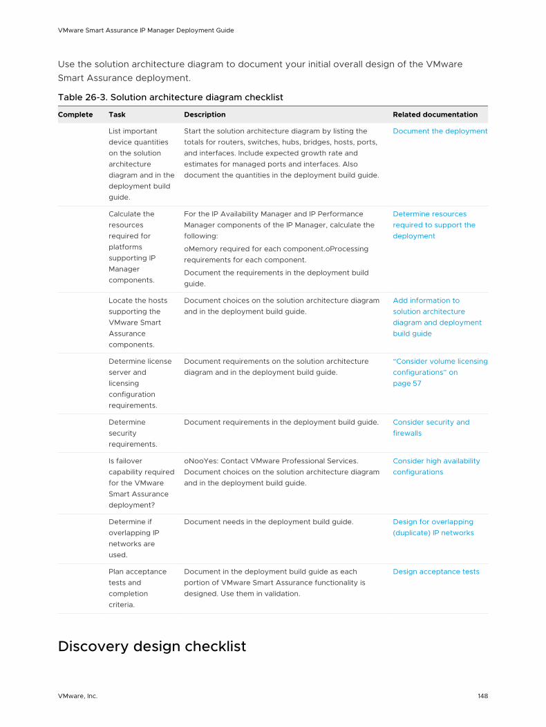
Use the solution architecture diagram to document your initial overall design of the VMware Smart Assurance deployment.
Table 26-3. Solution architecture diagram checklist
Complete Task Description Related documentation
List important device quantities on the solution architecture diagram and in the deployment build guide.
Start the solution architecture diagram by listing the totals for routers, switches, hubs, bridges, hosts, ports, and interfaces. Include expected growth rate and estimates for managed ports and interfaces. Also document the quantities in the deployment build guide.
Document the deployment
Calculate the resources required for platforms supporting IP Manager components.
For the IP Availability Manager and IP Performance Manager components of the IP Manager, calculate the following:
oMemory required for each component.oProcessing requirements for each component.
Document the requirements in the deployment build guide.
Determine resources required to support the deployment
Locate the hosts supporting the VMware Smart Assurance components.
Document choices on the solution architecture diagram and in the deployment build guide.
Add information to solution architecture diagram and deployment build guide
Determine license server and licensing configuration requirements.
Document requirements on the solution architecture diagram and in the deployment build guide.
“Consider volume licensing configurations” on page 57
Determine security requirements.
Document requirements in the deployment build guide. Consider security and firewalls
Is failover capability required for the VMware Smart Assurance deployment?
oNooYes: Contact VMware Professional Services. Document choices on the solution architecture diagram and in the deployment build guide.
Consider high availability configurations
Determine if overlapping IP networks are used.
Document needs in the deployment build guide. Design for overlapping (duplicate) IP networks
Plan acceptance tests and completion criteria.
Document in the deployment build guide as each portion of VMware Smart Assurance functionality is designed. Use them in validation.
Design acceptance tests
Discovery design checklist
VMware Smart Assurance IP Manager Deployment Guide
VMware, Inc. 148

Before using the IP Manager to discover the network, the requirements in the following checklist must be completed.
Table 26-4. Discovery design checklist
Complete Task Description Related documentation
Initial Discovery
Define a method for the initial topology discovery.
o Use a comprehensive seed file without autodiscovery.
o Use autodiscovery with a seed file or an agent.
Document the method in the deployment build guide.
Initial topology discovery
Topology Maintenance and Subsequent Discovery
Define a schedule for full discovery.
Define a regular schedule for full discovery. Choose a time of relative inactivity. Document the schedule in the deployment build guide. Include crontab or sm_sched control file entries if used.
Subsequent topology discovery and maintenance
Define a schedule for pending discovery.
Define a regular schedule for pending discovery. Choose a time of relative inactivity. Document the schedule in the deployment build guide. Include crontab or sm_sched control file entries if these utilities are used.
Subsequent topology discovery and maintenance
Determine if autodiscovery is appropriate.
Document choice in the deployment build guide. Subsequent topology discovery and maintenance
Choose a method for adding devices to the topology.
o Seed file without autodiscovery.
o Agent without autodiscovery.
o Use autodiscovery with a seed file or an agent.
Document choice in the deployment build guide.
Adding new systems to an existing topology
Prepare seed file or choose agent.
If a seed file will be used to add devices to the topology, obtain a list of devices with names or IP addresses. Document how to obtain the list or the location of the list in the deployment build guide. If an agent will be used instead, document the IP address or name of the agent.
Adding new systems to an existing topology
Define discovery filters.
If autodiscovery is enabled, configure autodiscovery filters. These are inclusive filters that add devices to the topology. Document the autodiscovery filter criteria in the deployment build guide.
Controlling autodiscovery with filters
Define an exclude filter.
To exclude specific devices, use the exclude filter in the discovery.conf file. This simplifies creation of the autodiscovery filters. Document exclude filter entries in the deployment build guide.
Controlling autodiscovery with filters
VMware Smart Assurance IP Manager Deployment Guide
VMware, Inc. 149

Table 26-4. Discovery design checklist (continued)
Complete Task Description Related documentation
Obtain SNMP security parameters per device.
Domain Managers use SNMP to poll the device agents. In order to do this, the Domain Manager needs the appropriate security information for the SNMP version: v1 and v2c use read community strings for every SNMPv1/v2c device that will be managed; v3 uses the username, SNMP engine ID (optional), authentication protocol and password (currently VMware, Inc. supports MD5 and SHA authentication protocols), privacy protocol and password (currently VMware, Inc. supports AES and DES privacy protocols), and context name, if used. These parameters will be needed during discovery. Document in the deployment build guide if permitted.
Discovery and security
Open necessary firewall ports.
If there is a firewall between any portions of the management infrastructure, certain TCP and UDP ports in the firewall must be opened for proper communications:
n SNMP polls: 161
n SNMP traps: 162
n Broker: 426
n License Manager: 1744
n Domain Managers (1 per manager): configurable
n VMware Smart Assurance Adapters, including the Syslog Adapter and the SNMP Trap Adapter (Receiver): configurable
Document the opened ports in the deployment build guide.
Discovery and security
Provide access to network devices to manage.
For each device that the IP Manager will monitor, the device’s access list must include the IP address of the hosts where Domain Managers are installed. The IP Manager must have full access to browse the MIBs of the devices. Document in the deployment build guide.
Discovery and security
Ensure DNS is properly configured.
For the IP Manager to name devices in its topology correctly, the DNS needs to be clean (proper forward and reverse lookup). If DNS is not used, use of an /etc/hosts file or not doing any name resolution at all can be considered.
Discovery and name resolution
Determine if discovery postprocessing is required.
Determine if discovery postprocessing using ASL rule sets will be used. Document in the deployment build guide.
Discovery and postprocessing customization
List unreachable IP addresses
If there are groups of IP addresses that are NOT normally reachable, assemble a list of IP ranges or some matching criteria so that the IP Manager will not unnecessarily ping these addresses. Document these addresses in the deployment build guide.
Discovery and postprocessing customization
Polling and threshold checklist
VMware Smart Assurance IP Manager Deployment Guide
VMware, Inc. 150

Table 26-5. Polling and threshold checklist
Complete Task DescriptionRelated documentation
Determine polling group requirements.
Design polling groups based on importance of network device performance both to the network and to the various parts of the organization. Also consider network latency to determine if changes are needed. Document choices in the deployment build guide.
Polling and polling groups
Set polling parameters for each polling group.
Set polling parameters based on importance of network device performance. Additional modifications might be necessary if polling does not present an accurate picture of network availability during validation. Document new polling parameters in the deployment build guide.
Polling and polling groups
Determine threshold group requirements.
Design threshold groups based on importance of network device performance both to the network and to the various parts of the organization. Document choices in the deployment build guide.
Thresholds and threshold groups
Set threshold parameters for each threshold group.
Set threshold parameters based on the expected effect of degraded performance on network operations. Additional modifications might be necessary during validation and as the organization gains experience with the performance indicators. Document new threshold parameters in the deployment build guide.
Thresholds and threshold groups
Syslog processing checklist (optional)
Table 26-6. Syslog processing checklist
Complete Task DescriptionRelated documentation
o Determine how to create the file for processing by the Syslog Adapter.
A file must be created that the Syslog Adapter can parse. Determine which devices will contribute messages to the file. Consistent layout of the messages in the file is required for Syslog Adapter processing. Include all details in the deployment build guide.
Creating the syslog file
o Determine the location of the file that the Syslog Adapter will process.
The process that is creating the file must be able to receive messages from source applications and the created file must be accessible by the Syslog Adapter. Include all details in the deployment build guide, including location, host and path.
Processing the syslog file
o Choose the messages that are most important for processing.
Choose the messages that are most important for processing. Include all details in the deployment build guide.
Processing the syslog file
VMware Smart Assurance IP Manager Deployment Guide
VMware, Inc. 151

Table 26-6. Syslog processing checklist (continued)
Complete Task DescriptionRelated documentation
o Determine the characteristics of the notifications that are generated.
For each message that generates a notification, determine the notification format. These characteristics will be used to develop the hook script for the VMware Smart Assurance syslog processing deployment. Include all details in the deployment build guide.
Processing the syslog file
o Add Syslog Processing to the solution architecture diagram.
Add Syslog Processing to the solution architecture diagram.
Processing the syslog file
VMWare deployment checklist (optional)
Table 26-7. VMWare deployment checklist
Complete Task DescriptionRelated documentation
o Check BIOS (Basic Input/Output System) settings.
Ensure that the following BIOS-specific settings are done to ensure compatibility with VMware ESX Server:
n Virtualization is enabled.
n Hyperthreading is turned off.
n All processor cores are enabled.
Test results
Test results
o Check for VMware configuation settings.
Check that the following VMWare settings are carried out:
n vSphere version is current, with all maintenance patches applied.
n VMware Tools is installed on each VM
n Auto notify for VMware Tools updates availability option is enabled, if not auto update.
n Latest virtualized network adapter (VMXNET3) is selected.
n vSwitch is configured such that it separates VM traffic from ESX management traffic.
n At least two vCPUs are assigned to SAM, and four vCPUs to IP.
n Maximum memory is available to VMs running the VMware Smart Assurance software.
VMware configuration guidelines
Test results
o Ensure general software recommendations are met.
Scheduling a software deployment varies based on the size and scope of the deployment and the organization’s requirements. Some prerequisites include ensuring that:
n All VMs are running the same OS version and patch level.
n All VMware Smart Assurance servers are at the same version and patch level.
VMware configuration guidelines
VMware Smart Assurance IP Manager Deployment Guide
VMware, Inc. 152