Embed Size (px)
Citation preview
0
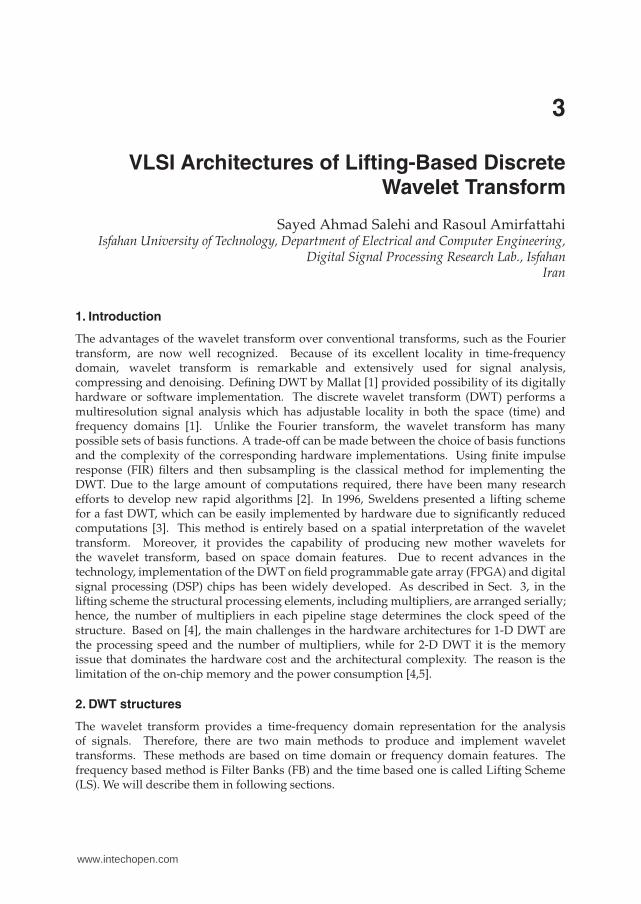
VLSI Architectures of Lifting-Based DiscreteWavelet Transform
Sayed Ahmad Salehi and Rasoul AmirfattahiIsfahan University of Technology, Department of Electrical and Computer Engineering,
Digital Signal Processing Research Lab., IsfahanIran
1. Introduction
The advantages of the wavelet transform over conventional transforms, such as the Fouriertransform, are now well recognized. Because of its excellent locality in time-frequencydomain, wavelet transform is remarkable and extensively used for signal analysis,compressing and denoising. Defining DWT by Mallat [1] provided possibility of its digitallyhardware or software implementation. The discrete wavelet transform (DWT) performs amultiresolution signal analysis which has adjustable locality in both the space (time) andfrequency domains [1]. Unlike the Fourier transform, the wavelet transform has manypossible sets of basis functions. A trade-off can be made between the choice of basis functionsand the complexity of the corresponding hardware implementations. Using finite impulseresponse (FIR) filters and then subsampling is the classical method for implementing theDWT. Due to the large amount of computations required, there have been many researchefforts to develop new rapid algorithms [2]. In 1996, Sweldens presented a lifting schemefor a fast DWT, which can be easily implemented by hardware due to significantly reducedcomputations [3]. This method is entirely based on a spatial interpretation of the wavelettransform. Moreover, it provides the capability of producing new mother wavelets forthe wavelet transform, based on space domain features. Due to recent advances in thetechnology, implementation of the DWT on field programmable gate array (FPGA) and digitalsignal processing (DSP) chips has been widely developed. As described in Sect. 3, in thelifting scheme the structural processing elements, including multipliers, are arranged serially;hence, the number of multipliers in each pipeline stage determines the clock speed of thestructure. Based on [4], the main challenges in the hardware architectures for 1-D DWT arethe processing speed and the number of multipliers, while for 2-D DWT it is the memoryissue that dominates the hardware cost and the architectural complexity. The reason is thelimitation of the on-chip memory and the power consumption [4,5].
2. DWT structures
The wavelet transform provides a time-frequency domain representation for the analysisof signals. Therefore, there are two main methods to produce and implement wavelettransforms. These methods are based on time domain or frequency domain features. Thefrequency based method is Filter Banks (FB) and the time based one is called Lifting Scheme(LS). We will describe them in following sections.
3
www.intechopen.com

2 Will-be-set-by-IN-TECH
2.1 Filter banks structure
In the FB method, for one level of wavelet decomposition, the input signal is divided into twoseparate frequency parts by passing it simultaneously through a pair of low pass, H(z), andhigh pass, G(z), filters, as shown in Fig. 1. Then, subsampling the filter’s output to producethe low pass and high pass outputs (s,d). Therefore, the FB method performs the DWT basedon convolving filter taps and samples of the input signal. H(z) and G(z) can be written in thisform:
H(z) = h0 + h1z−1 + h2z−2 + ... + hN z−N
G(z) = g0 + g1z−1 + g2z−2 + ...+ gMz−M.
G(z) 2d
H(z) 2s
x
Fig. 1. Filter Banks Block diagram
As an example consider the CDF(2,2) wavelet. H(z) and G(z) for this transform are
H(z) =−1
4√
2z2 +
1
2√
2z +
3
2√
2+
1
2√
2z−1 +
−1
4√
2z−2.
G(z) =−1
2√
2z2 +
1√
2z +
−1
2√
2
The low pass filter has 5 taps and the high pass has 3 taps, so we call it 5/3 wavelet. AlthoughFB structure is the prior one but it is only capable of providing wavelet transforms in thefrequency domain and not in the time domain. Moreover, in general, the FB filter coefficientsare not integer numbers; hence, they are not appropriate for hardware implementation. Inaddition, the number of arithmetic computations in the FB method is very large.
2.2 Lifting structure
The LS method is a new method for constructing and performing wavelets based on the time(space) domain [3].As shown in Fig. 2, at first the LS structure splits the input signal samples into even and oddsamples. Then P function is applied on even samples as a prediction function. The wordprediction is used here because P function predicts odd samples using even samples.Thedifference between this prediction and the actual value of odd sample, creates the highfrequency part of the signal which is called "detail" coefficients (d). Then applying the Ufunction on detail signal and combining the result with even samples update them so that theoutput coefficients (s) have the desired properties. Usually the desired properties of s is thesame as the properties of input signal (x) but with half size. So the s signal is an approximationfor x and is called approximation coefficient.Note that the details and approximation coefficients (d,s) in lifting scheme, respectively, arethe same as high pass and low pass outputs in FB.Based on the above description we have
d = xodd − P(xeven),
42 Discrete Wavelet Transforms: Algorithms and Applications
www.intechopen.com

VLSI Architectures of Lifting-Based Discrete Wavelet Transform 3
for prediction block ands = xeven + U(d)
for update block.Equations for P and U functions are determined based on the implemented wavelet, also thenumber and arrangement of P and U blocks in the lifting structure are different for varioustypes of wavelets.
split P U
-
+x
x
x
d
s
Fig. 2. Block diagram of a lifting stage
We can write matrix equations for P and U blocks respectively as following:[
xeven(z)d(z)
]
=
[1 0
t(z) 1
]
︸ ︷︷ ︸
P
[xeven(z)xodd(z)
]
[s(z)d(z)
]
=
[1 s(z)0 1
]
︸ ︷︷ ︸
U
[xeven(z)
d(z)
]
.
Generally speaking, if we have more than one lifting step, the matrix equation is(3):[
s(z)d(z)
]
=
[k 00 1/k
] m
∏i=1
[1 si(z)0 1
] [1 0
ti(z) 1
] [xeven(z)xodd(z)
]
(1)
In (1), k and 1/k are normalization factors. The last matrix is used only for normalizationand may be omitted in many applications such as compression. The relation between FBcoefficients and LS equations is (3):
E(z) =
[he(z) ho(z)ge(z) go(z)
]
=
[k 00 1/k
] m
∏i=1
[1 si(z)0 1
] [1 0
ti(z) 1
]
Matrix E(z) is called a polyphase matrix, where according to the FB structure, he and ho areeven and odd taps of the low pass filter and ge and go are even and odd taps of the highpass filter, respectively. si(z) and ti(z) are related to filter coefficients in FB structure. In otherwords si(z) and ti(z) can be obtained from FB by factorization algorithm presented in [5].Example: Let consider the previous example, 5/3 wavelet, in LS. This wavelet consist of onelifting step (one P unit and one U unit together is a lifting step). For this wavelet the predictionof each odd sample in signal is the average of two adjacent even samples. Then P blockcalculates the difference between the real value of signal sample and its prediction:
d(n) = x(2n + 1)−1
2[x(2n) + x(2n + 2)].
U block updates even samples to have the same property as the original signal. It uses twomost recently computed differences for update procedure:
s(n) = x(2n) +1
4(d(n − 1) + d(n)).
43VLSI Architectures of Lifting-Based Discrete Wavelet Transform
www.intechopen.com

4 Will-be-set-by-IN-TECH
So the matrix equation for 5/3 wavelet is
[s(z)d(z)
]
=
[√2 0
0 1√2
] [1 1
4 (1 + z−1)0 1
] [1 0
−12 (1 + z) 1
]
︸ ︷︷ ︸
E(z)
[xeven(z)xodd(z)
]
and the polyphase matrix is
E(z) =
[−1
4√
2z−1 + 3
2√
2− 1
4√
2z 1
2√
2z−1 + 1
2√
2−1
2√
2− 1
2√
2z 1√
2
]
.
We propose the following lemma for using in hardware implementation of LS as will bedescribe in section 3.1.Lemma1: Factorization can be done so that si(z) and ti(z) are first-order or lower-orderpolynomials.Proof sketch: After a polyphase matrix representing a wavelet transform with finite filtersis factored into lifting steps, each step becomes a Laurent polynomial. Since the differencebetween the degrees of the even and odd parts of a polynomial is never greater than 2, it isalways possible to find the common divisor of the first-order or lower-order polynomials.Also, the lifting factorization process is non-unique and so there is freedom in the formof factorization. Hence, a classical wavelet filter can always be factored into first-order orlower-order Laurent polynomials (i.e., si(z) or ti(z)).�Compared to the FB method, the LS method has many advantages [6,7]. The most importantone is the number of arithmetic computations. In the LS method, the number of arithmeticoperations, additions and multiplications, is nearly one-half of that of the FB, which is whythe LS structure is more efficient. Even the amount of computations in some types of DWTcan be reduced to a quarter of that needed for FB [8]. Furthermore the LS structure hasthe advantage of implementing the Integer Wavelet Transform (IWT) efficiently. IWT is awavelet-like transform in which all of the decomposition coefficients are integer [9]. The IWTis appropriate for hardware implementation of the DWT [10]. The practical advantages ofusing the lifting-based IWT have been described in [11]. Moreover, by using the LS, it is easyto implement the DWT in a fully in-place method, which is memory efficient [2,12].Regarding the above explanation, the LS structure is used to implement 5/3 and 9/7 wavelets,which are used, respectively, for lossless and lossy compression in the JPEG 2000 standard.
3. 1-DDWT
In this section, some types of lifting-based DWT processing elements and 1-D structures areexplained.
3.1 Basic functional units for lifting scheme
As pointed out in Lema1, factorization can be done so that si(z) and ti(z) are first order orlower-order polynomials. Figure 3 shows three possible categories of the basic processingunit and the related polynomials in such a factorization. Different kinds of lifting-based DWTarchitectures can be constructed by combining the three basic lifting elements. Most of theapplicable DWTs like 9/7 and 5/3 wavelets consist of processing units, as shown in Fig. 3(a),which is simplified as Fig. 4. This unit is called the processing element (PE). In Fig. 4, A, Band C are input samples which arrive successively. To implement the P unit, A and C receive
44 Discrete Wavelet Transforms: Algorithms and Applications
www.intechopen.com

VLSI Architectures of Lifting-Based Discrete Wavelet Transform 5
ZC
+
+
×a
B
D
A
a(1+z-1)
ZC
+
×
+
a
B
D
A
a+bz-1
+
×a
B
D
A
a
× b
Fig. 3. Basic functional units for LS
Fig. 4. Most convenient basic PE for LS
even samples while B receives odd samples. On the other hand, for the U unit, A and Care odd samples and B receives even samples. Now, the structure of Fig. 4 can be used toimplement 5/3 and 9/7 wavelets. For instance, Fig. 5 and Fig. 6 shows the architecture ofthe 5/3 and 9/7 wavelets respectively, where each white circle represents a PE. In Fig. 6, the
R R
P
U
R
Fig. 5. Lifting Structure for 5/3 wavelet
R R
P
P
U
U
R
Fig. 6. Lifting Structure for 9/7 wavelet
input and output layers are essential (basic) layers and are fixed for each wavelet type, whileby changing the number of extended layers, the type of wavelet can be changed accordingly.For example, omission of a single extended (added) layer in Fig. 6 will change the relatedarchitecture from 9/7 type to 5/3 type. The black circles in Fig. 6 represent needed stored datafor computing outputs (s,d). R0, R1 and R2, are registers that get their values from new inputsamples and are called data memory. The other three black circles which store the resultsof previous computations are known as temporary memory. The number of data memory
45VLSI Architectures of Lifting-Based Discrete Wavelet Transform
www.intechopen.com
6 Will-be-set-by-IN-TECH
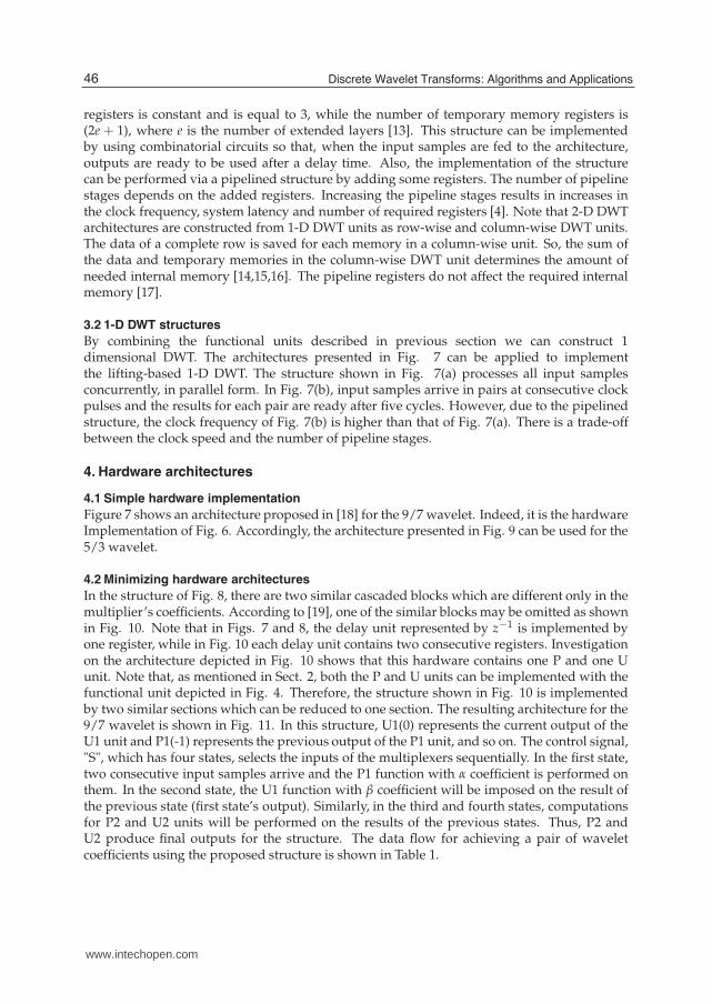
registers is constant and is equal to 3, while the number of temporary memory registers is(2e + 1), where e is the number of extended layers [13]. This structure can be implementedby using combinatorial circuits so that, when the input samples are fed to the architecture,outputs are ready to be used after a delay time. Also, the implementation of the structurecan be performed via a pipelined structure by adding some registers. The number of pipelinestages depends on the added registers. Increasing the pipeline stages results in increases inthe clock frequency, system latency and number of required registers [4]. Note that 2-D DWTarchitectures are constructed from 1-D DWT units as row-wise and column-wise DWT units.The data of a complete row is saved for each memory in a column-wise unit. So, the sum ofthe data and temporary memories in the column-wise DWT unit determines the amount ofneeded internal memory [14,15,16]. The pipeline registers do not affect the required internalmemory [17].
3.2 1-D DWT structures
By combining the functional units described in previous section we can construct 1dimensional DWT. The architectures presented in Fig. 7 can be applied to implementthe lifting-based 1-D DWT. The structure shown in Fig. 7(a) processes all input samplesconcurrently, in parallel form. In Fig. 7(b), input samples arrive in pairs at consecutive clockpulses and the results for each pair are ready after five cycles. However, due to the pipelinedstructure, the clock frequency of Fig. 7(b) is higher than that of Fig. 7(a). There is a trade-offbetween the clock speed and the number of pipeline stages.
4. Hardware architectures
4.1 Simple hardware implementation
Figure 7 shows an architecture proposed in [18] for the 9/7 wavelet. Indeed, it is the hardwareImplementation of Fig. 6. Accordingly, the architecture presented in Fig. 9 can be used for the5/3 wavelet.
4.2 Minimizing hardware architectures
In the structure of Fig. 8, there are two similar cascaded blocks which are different only in themultiplier’s coefficients. According to [19], one of the similar blocks may be omitted as shownin Fig. 10. Note that in Figs. 7 and 8, the delay unit represented by z−1 is implemented byone register, while in Fig. 10 each delay unit contains two consecutive registers. Investigationon the architecture depicted in Fig. 10 shows that this hardware contains one P and one Uunit. Note that, as mentioned in Sect. 2, both the P and U units can be implemented with thefunctional unit depicted in Fig. 4. Therefore, the structure shown in Fig. 10 is implementedby two similar sections which can be reduced to one section. The resulting architecture for the9/7 wavelet is shown in Fig. 11. In this structure, U1(0) represents the current output of theU1 unit and P1(-1) represents the previous output of the P1 unit, and so on. The control signal,"S", which has four states, selects the inputs of the multiplexers sequentially. In the first state,two consecutive input samples arrive and the P1 function with α coefficient is performed onthem. In the second state, the U1 function with β coefficient will be imposed on the result ofthe previous state (first state’s output). Similarly, in the third and fourth states, computationsfor P2 and U2 units will be performed on the results of the previous states. Thus, P2 andU2 produce final outputs for the structure. The data flow for achieving a pair of waveletcoefficients using the proposed structure is shown in Table 1.
46 Discrete Wavelet Transforms: Algorithms and Applications
www.intechopen.com

VLSI Architectures of Lifting-Based Discrete Wavelet Transform 7
x x x x
P
P
U
U
(a)x x
x xT=0
T=1
T=2
T=3
(b)
Fig. 7. 1-D DWT structures based on lifting a)parallel architecture b) sequential-pipelinedarchitecture
Zi1
+
+
×α
P1
Z +
+
×β
i0
Z Z
+
+
×γ
P2
Z +
+
×δ
U1
Z
U2
o1
o0
Fig. 8. Lifting-based hardware architecture for 9/7 wavelet
S in1 in2 out F(factor)0 i1 i0 P1 α
1 i0(-1) P1 U1 β2 P1(−1) U2 P2 γ3 U1(−1) P2 U2 ζ
Table 1. Time sequence for structure of Fig. 11
The calculation of consecutive wavelet coefficients is periodic and continuous; therefore, thesequence of control signal "S" for data flow can be easily generated by a simple logic circuit.Figure 11 shows the hardware architecture for Fig. 11. The 5/3 wavelet implementation ofthe proposed architecture is depicted in Fig. 13. It is clear that only the number of coefficients
47VLSI Architectures of Lifting-Based Discrete Wavelet Transform
www.intechopen.com

8 Will-be-set-by-IN-TECH
i1
+
+
×-1/2
R1
+
+
×1/4
i0
o1
o0
R2
R0
Fig. 9. Lifting-based hardware architecture for 5/3 wavelet
i1
i0
Z
+
+
×γ
Z +
+
×
Zo1
o0
αδ
β
Fig. 10. Propose architecture in [19]
Z
in2
+
+
×F
in1 out
s
s
s
Fig. 11. Minimized structure
and delay block registers, that is, the z−1 blocks, have been modified from four to two. So,changing the wavelet type changes these two quantities, coefficients and registers, only. BothP and U units in LS can be implemented by means of the PE shown in Fig. 4. We exploredthis feature in the previous section and implemented a 1-D DWT structure containing onlyone PE. We call this method the "folded method". The folded structure is an alternative for theproposed method in [12] by which the lifting-based structures can be designed systematically.As shown in Fig. 14 for 9/7 wavelet, the method in [12] produces systolic architecture, butfolded method produces folded architecture. In folded structure, the output of the PE unit isfed back through the delay registers to the PE’s input. By incorporating different numbers ofdelay registers and coefficients with PE, the structure for different wavelets can be designed.For example the folded structure for 5/3 and 9/7 wavelets has two and four delay registers,respectively. Also the coefficients for 5/3 wavelet are −1
2 and 14 while for 9/7 they are α, β, γ, δ.
48 Discrete Wavelet Transforms: Algorithms and Applications
www.intechopen.com

VLSI Architectures of Lifting-Based Discrete Wavelet Transform 9
+
+
×
out
s
s
s
Fig. 12. Hardware implementation for Fig.10
+
+
×
out
s
s
s
Fig. 13. Minimized architecture for 5/3 wavelet
(a) Systolic method
PE
out
(b) Folded method
Fig. 14. 1-D Lifting-Based DWT for 9/7 wavelet by Systematic Design Method
In order to show the efficiency of our architecture, several architectures are chosen forcomparison. Ignoring the pipeline registers, the results of comparison for the 9/7 wavelet aregiven in Table 2. It is obvious that compared to other architectures, the number of processingunits is reduced in the folded architecture, thus requiring less area to implement the DWT.Having smaller 1-D DWT units is very effective in multidimensional architectures or in 2-DDWT, where it is needed to increase the number of 1-D DWT units to achieve a higherperformance [20]. The cost is that, in the proposed architecture, the clock pulses requiredto compute outputs are more than those in the previous architectures. This requirement isdue to the sequential states required to complete the computation of each output.
49VLSI Architectures of Lifting-Based Discrete Wavelet Transform
www.intechopen.com

10 Will-be-set-by-IN-TECH
Architecture Multiplier Adder RegisterLifting[18] 4 8 6
Proposed in [19] 2 4 6Systolic[12] 4 8 4Folded [30] 1 2 4
Table 2. Comparison of some different 1-D DWT architectures for 9/7 wavelet (J −→ ∞)
5. 2-D DWT structures
In this section, we review four convenient structures for 2-D DWT. It is assumed that the 2-Dwavelets reviewed in the following structures are separable, so that the 2-D wavelet transformcan be reduced to a 1-D wavelet transform performed on rows and columns, respectively.In the direct method (step-by-step method), shown in Fig. 15, the input frame, stored inexternal memory, arrives at the 1-D DWT, row by row. The primary outputs are waveletcoefficients in the row direction and are stored in the external memory. After scanning allthe rows of the frame, again the coefficients are transferred from the external memory to the1-D DWT block, but this time in the column-wise direction. The secondary outputs of the1-D DWT block are 2-D DWT coefficients of the input frame, which are stored in the externalmemory again. If computation of coefficients for one more decomposition level is needed, thisprocedure must be repeated for the LL part of the previous level, whose size is a quarter of theinput frame size. This routine will be repeated for higher levels. The direct method hardwareis simple, but its latency and the number of external memory accesses are large. The numberof external memory accesses for computing a J-level 2-D DWT of an N × N input image canbe calculated by the expression below, where half of the sum is related to the external memoryreads and the other half is related to the external memory writes
4 × (1 +1
4+
1
16+ · · ·+ (
1
4)J−1)× N2 (2)
1-D
DWT
External memory
(N*N)
Fig. 15. Direct method
The line-based method can be implemented in two forms: single level and multilevel. In theline-based single level method, which is shown in Fig. 16, each level of DWT is performed bya 2-D DWT block. In this method, only internal memory is used to compute one level DWTfor both the row and column directions, hence, there is no external memory access duringthe computation of one level 2-D DWT (except for reading rudimentary inputs and writingfinal results for that level). The required internal memory is the sum of the data memory andthe temporal memory (black circles shown in Fig. 6) for each line. So the amount of neededinternal memory is 6N for 9/7 wavelet and 4N for 5/3 wavelet [13,21]. But the results of theDWT in the row direction for even rows can be used for the computation of the DWT in thecolumn direction without storing them. Hence, the required internal memory for 9/7 and 5/32-D wavelets is reduced to 5N and 3N, respectively. Recently, some new modifications havebeen made for the 2-D DWT block. For example, in [20] the number of data entrances has beenincreased by using more 1-D DWT units in the 2-D DWT block. Although this modification
50 Discrete Wavelet Transforms: Algorithms and Applications
www.intechopen.com

VLSI Architectures of Lifting-Based Discrete Wavelet Transform 11
increases the speed, it requires more internal memory and the size of the circuit is increased.In [22], by replacing registers with line buffers and controlling data flow in a structure like Fig.13, with 5 more registers, a 2-D DWT block for 5/3 wavelet has been proposed.Obviously, for a higher-level 2-D DWT, only LL coefficients of the previous level are used, sothe total number of external memory access for a J-level 2-D DWT on an N × N image is
2 × (1 +1
4+
1
16+ · · ·+ (
1
4)J−1)× N2 (3)
The structure of Fig. 17 performs all levels of 2-D DWT, using only internal memory. So,
1-level
2-D DWT
External memory
(N*N)
Fig. 16. Single level line-based method
the total number of external memory accesses for a J-level 2-D DWT is limited to 2N2, whichcorresponds to reading the input image for the first level and writing the final DWT results.The line-based multilevel structure, shown in Fig. 17, is much faster than the previousstructures, but it needs a larger amount of hardware and so its hardware utilization (i.e., theaverage value of the area of working parts versus the whole area of the hardware) is low [23],but the 2-D recursive architecture proposed in [24] improves the hardware utilization for theJ-level 2-D DWT. In Fig. 17, the required internal memory for the 9/7 wavelet is obtained fromequation (4).
5N × (1 +1
2+
1
4+ · · ·+ (
1
2)J−1) (4)
J-level
2-D DWT
External memory
(N*N)
Fig. 17. Multilevel line-based method
There is a trade-off between the size of the internal memory and the number of externalmemory accesses in the 2-D DWT structures mentioned previously. Now, a block-basedstructure that parameterizes the aforementioned trade-off is introduced. The block-basedstructure is similar to the line-based method, but instead of considering the total length ofa row for DWT in the row direction, only a part of it with length M pixels is considered (Fig.18). It means that the first M columns of the main frame (the gray area in Fig. 18) are usedas the input frame and 2-D DWT coefficients are computed for them. So the required internalmemory, which is determined by the length of the rows, is decreased. As an example, for the9/7 wavelet the internal memory size will be decreased from 5N to 5M (where M is a fractionof N). It is possible to consider a block of image by partitioning the image in both the row andcolumn directions. In this method, the block (or window) slides across the image and boththe row- and column-wise 1-D DWT will be performed on them [25]. The size of tile windowsmay be reduced to 2 × 2 pixels [26].
51VLSI Architectures of Lifting-Based Discrete Wavelet Transform
www.intechopen.com

12 Will-be-set-by-IN-TECH
Fig. 18. Scan method in block-based structure
6. Scan methods for block-based structure
However, in the above-mentioned method, there is a problem in the boundary region betweentwo M-pixel sections. To compute the DWT for the beginning pixel of the nextM-pixel section,values of K previous pixels are needed. These K pixels produce values of temporary memory(black circles shown in Fig. 19). K is equal to nt − 2, where nt is the number of filter tapscorresponding to the desired DWT. For the 9/7 wavelet, as shown in Fig. 19, K is equal to7 (shaded circles). To solve the boundary problem, the overlapped scan method has been
Fig. 19. Boundary region for 9/7 wavelet
proposed in [27]. A new M-pixel section begins from the last K pixels in the previous section.So two sections are overlapped in K pixels, and this causes the number of external memory
reads to be N2 M(M−K)
instead of N2. The number of external memory writes is limited to writing
the output results and is equal to N2.We can use an alternate scan method for the overlapped region at the boundary between twoM-pixel sections. The relationships for the new scan method are different from the previousmethod. The temporary memory at the boundary of two M-pixel sections (black circles in Fig.19) can be saved for the computation of the next section. These saved values will be usedfor the computation of the next M pixels. Hence, a new M-pixel section begins without anyoverlap with the previous section. The required memory to save temporary data is L × N,where L is the value of the temporary memory in the related DWT core. For example, in Fig.
52 Discrete Wavelet Transforms: Algorithms and Applications
www.intechopen.com

VLSI Architectures of Lifting-Based Discrete Wavelet Transform 13
Direct Single level line-based Block-Based
Internal Memory Size 0 5N 5M 5M
External Memory Reads 2N2 N2 N2 MM−K N2(1 + 4
M )− 4N
External Memory Write 2N2 N2 N2 N2(1 + 4M )− 4N
Control complexity Low Medium Medium Medium
Table 3. Comparison of different 2-D DWT structures for one level 9/7 wavelet
19, L is 4 for the 9/7 wavelet without pipelining. The storage of temporary memory may befulfilled in internal or external memory. If internal memory is used to save temporary data, thenumber of external memory accesses is equal to N2 read and N2 write operations. However,if external memory is used to save temporary memory, both of the external memory reads andwrites are increased by an amount of ( N
M − 1)N × L. Hence, the number of external memory
reads as well as the number of external memory writes is equal to N2 + ( NM − 1)N × L. In
this expression, the ( NM − 1) coefficient is the number of M-pixel sections. Due to hardware
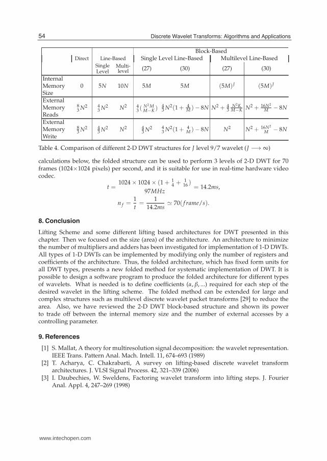
limitations (the limit size of internal memory on FPGA ICs), we select the second case forimplementation. Comparisons of the aforementioned methods for one level 2-D DWT aregiven in Table 3. The table shows the values of the internal memory size and external memoryaccesses for the three algorithms. It is shown that in our proposed algorithm the internalmemory size is between those of two other algorithms (the direct method and the line-basedmethod). The same conclusion is true for the external memory size. The table also showsthe order of complexity for the control circuits of these methods based on [28]. Similarcomparisons for J-level (J −→ ∞) 2-D DWT are given in Table 4. Note that M has beenconsidered to be fixed for all levels of 2-D DWT. It means that the width of the M-pixel sectionfor the current level is the same as the one in the previous level. The J-level structure canbe implemented either in the form of a single level (Fig. 15) or multilevel structure (Fig.16), and the relevant values are listed in Table 4. We observe that the parameter M can bedetermined according to hardware limitations, such as internal memory. The conclusion fromthe two tables is that the block-based structure with the new scan method, in comparisonwith the direct method, needs more internal memory, but needs only about one-half of theexternal memory accesses. Due to the shorter access time for internal memory, the clockpulse frequency will increase, and based on the energy model in [5] the power consumptionwill decrease. In comparison with other methods, the new method remarkably decreasesthe needed internal memory at the cost of a soft increase in the number of external memoryaccesses.
7. Experimental results
The folded 1-D DWT architecture was described in VHDL code and simulated byActive-HDL6.3 software. Then the relevant VHDL code was synthesized by the Synplify7.5.1software tool to be implemented on IC XC2V40 (from the VirtexII family of Xilinx FPGAs).The maximum estimated frequency for implementing Fig. 12 on this IC is 122.4 MHz, whichis practical for real-time implementation of the 9/7 wavelet for large images. The maximumfrequency to implement the 5/3 wavelet on the IC is 163.1 MHz. Also, the block-basedarchitecture with the new scan method was modeled and simulated for the 5/3 wavelet withN = 1024 and 8-bit pixels. The code was synthesized by Synplify7.5.1 for implementation onVirtexII. After post place and route simulation, the clock pulse frequency achieved was 97MHz. The structure receives one pixel as input per each clock pulse. So, according to the
53VLSI Architectures of Lifting-Based Discrete Wavelet Transform
www.intechopen.com
14 Will-be-set-by-IN-TECH
Block-BasedDirect Line-Based Single Level Line-Based Multilevel Line-Based
SingleLevel
Multi-level (27) (30) (27) (30)
InternalMemorySize
0 5N 10N 5M 5M (5M)J (5M)J
ExternalMemoryReads
83 N2 4
3 N2 N2 43 (
N2 MM−K )
43 N2(1 + 4
M )− 8N N2 + 43
N2KM−K N2 + 16N2
M − 8N
ExternalMemoryWrite
83 N2 4
3 N2 N2 43 N2 4
3 N2(1 + 4M )− 8N N2 N2 + 16N2
M − 8N
Table 4. Comparison of different 2-D DWT structures for J level 9/7 wavelet (J −→ ∞)
calculations below, the folded structure can be used to perform 3 levels of 2-D DWT for 70frames (1024×1024 pixels) per second, and it is suitable for use in real-time hardware videocodec.
t =1024 × 1024 × (1 + 1
4 + 116 )
97MHz= 14.2ms,
n f =1
t=
1
14.2ms� 70( f rame/s).
8. Conclusion
Lifting Scheme and some different lifting based architectures for DWT presented in thischapter. Then we focused on the size (area) of the architecture. An architecture to minimizethe number of multipliers and adders has been investigated for implementation of 1-D DWTs.All types of 1-D DWTs can be implemented by modifying only the number of registers andcoefficients of the architecture. Thus, the folded architecture, which has fixed form units forall DWT types, presents a new folded method for systematic implementation of DWT. It ispossible to design a software program to produce the folded architecture for different typesof wavelets. What is needed is to define coefficients (α, β, ...) required for each step of thedesired wavelet in the lifting scheme. The folded method can be extended for large andcomplex structures such as multilevel discrete wavelet packet transforms [29] to reduce thearea. Also, we have reviewed the 2-D DWT block-based structure and shown its powerto trade off between the internal memory size and the number of external accesses by acontrolling parameter.
9. References
[1] S. Mallat, A theory for multiresolution signal decomposition: the wavelet representation.IEEE Trans. Pattern Anal. Mach. Intell. 11, 674–693 (1989)
[2] T. Acharya, C. Chakrabarti, A survey on lifting-based discrete wavelet transformarchitectures. J. VLSI Signal Process. 42, 321–339 (2006)
[3] I. Daubechies, W. Sweldens, Factoring wavelet transform into lifting steps. J. FourierAnal. Appl. 4, 247–269 (1998)
54 Discrete Wavelet Transforms: Algorithms and Applications
www.intechopen.com

VLSI Architectures of Lifting-Based Discrete Wavelet Transform 15
[4] C.-T. Huang, P.-C. Tseng, L.-G. Chen, Flipping structure: an efficient VLSI architecturefor liftingbased discrete wavelet transform, IEEE Trans. Signal Process. 52 (2004), pp.1080–1089
[5] N.D. Zervas et al., Evaluation of design alternatives for the 2-D-discrete wavelettransform. IEEE Trans. Circuits Syst. Video Technol. 11(12), 1246–1262 (2001)
[6] K. A. Kotteri, S. Barua, A. E. Bell, and J. E. Carletta, "A comparison of hardwareimplementations of the biorthogonal 9/7 DWT: convolution versus lifting," IEEE Trans.Circuits Syst. II, Expr. Br., vol. 52, no. 5, pp. 256-260, 2005.
[7] M. Maurizio, M. Guido, P. Gianluca, and Z. Maurizio, "Novel JPEG 2000 compliant DWTand IWT VLSI implementations," J. VLSI Signal Process., vol. 35, no. 2, pp. 137-153, Sep.2003.
[8] J. Reichel, On the arithmetic and bandwidth complexity of the lifting scheme, in Proc. ofInternational Conference on Image Processing (2001), pp. 198–201
[9] R. Calderbank, I. Daubechies, W. Sweldens, B.-L. Yeo, Wavelet transforms that mapintegers to integers. Appl. Comput. Harmon. Anal. 5(3), 332–369 (1998)
[10] A. Jensen, A. La Cour-Harbo, Ripples in Mathematics: The Discrete Wavelet Transform(Springer, Berlin, 2001)
[11] K.G. Oweiss et al., A scalable wavelet transform VLSI architecture for real-time signalprocessing in high-density intra-cortical implants. IEEE Trans. Circuits Syst. 54(6),1266–1278 (2007)
[12] C.-T. Huang, P.-C. Tseng, L.-G. Chen, Efficient VLSI architectures of lifting-based discretewavelet transform by systematic design method, in IEEE International Symposium onCircuits and Systems, vol. 5 (2002), pp. 565–568
[13] W.-H. Chang, Y.-S. Lee, W.S. Peng, C.-Y. Lee, A line-based, memory efficient andprogrammable architecture for 2D DWT using lifting scheme, in IEEE InternationalSymposium on Circuits and Systems, vol. 4 (2001), pp. 330–333
[14] K. Andra, C. Chakrabarti, T. Acharya, A VLSI architecture for lifting-based forward andinverse wavelet transform. IEEE Trans. Signal Process. 50(4), 966–977 (2002)
[15] O. Fatemi, S. Bolouki, Pipeline memory-efficient and programmable architecture for 2Ddiscrete wavelet transform using lifting scheme, in Proceedings of IEE Circuits, Devicesand Systems, December 2005, pp. 703–708
[16] Lan, N. Zheng, Y. Liu, Low power and high-speed VLSI architecture for lifting-basedforward and inverse wavelet transform. IEEE Trans. Consumer Electron. 51(2), 379–385(2005)
[17] C.Y. Xiong, J.W. Tian, J. Liu, A note on Sflipping structure: an efficient VLSI architecturefor liftingbased discrete wavelet transformT. IEEE Trans. Signal Process. 54(4), 1910–1916(2006)
[18] J.M. Jou, Y.H. Shiau, C.C. Lio, Efficient VLSI architectures for the biorthogonal wavelettransform by filter bank and lifting scheme, in Proceedings of IEEE ISCAS 2001, pp.529–533
[19] C.J. Lian, K.F. Chen, H.H. Chen, L.G. Chen, Lifting based discrete wavelet transformarchitecture for JPEG2000, in IEEE International Symposium on Circuits and Systems(ISCAS 2001) Sydney, May 2001
[20] C.Y. Xiong, J.W. Tian, J. Liu, Efficient architectures for two-dimensional discrete wavelettransform using lifting scheme. IEEE Trans. Image Process. 16(3), 607–614 (2007)
55VLSI Architectures of Lifting-Based Discrete Wavelet Transform
www.intechopen.com
16 Will-be-set-by-IN-TECH
[21] P.-C. Tseng, C.-T. Huang, L.-G. Chen, Generic RAM-based architecture fortwo-dimensional discrete wavelet transform with line-based method, in Asia-PacificConference on Circuits and Systems (2002), pp. 363–366
[22] H. Varshney, M. Hasan, S. Jain, Energy efficient novel architectures for the lifting-baseddiscrete wavelet transform. IET Image Process. 1(3), 305–310 (2007)
[23] C.-T. Huang, P.-C. Tseng, L.-G. Chen, Hardware implementation of shape-adaptivediscrete wavelet transform with the JPEG2000 defaulted 9/7 filter bank, in IEEEInternational Conference on Image Processing, vol. 3 (2003), pp. 571–574
[24] L.Hongyu, M.K. Mandal, B.F. Cockburn, Efficient architectures for 1-D and 2-Dlifting-based wavelet transforms. IEEE Trans. Signal Process. 52(5), 1315–1326 (2004)
[25] C.H. Yang et al., A block-based architecture for lifting scheme discrete wavelet transform.IEICE Trans. Fundam. 90(5), 1062–1071 (2007)
[26] J.W. Kim et al., Tiled interleaving for multi-level 2-D discrete wavelet transform, in IEEEInt. Symp. Circuits Syst., May 2007, pp. 3984–3987
[27] C.-T. Huang, P.-C. Tseng, L.-G. Chen, Memory analysis and architecture fortwo-dimensional discrete wavelet transform, in IEEE International Symposium onCircuits and Systems (ISCAS 2004)
[28] C.-T. Huang, P.-C. Tseng, L.-G. Chen, Analysis and VLSI architecture for 1-D and 2-Ddiscrete wavelet transform. IEEE Trans. Signal Process. 53(4), 1575–1586 (2005)
[29] C. Wang, W.S. Gan, Efficient VLSI architecture for lifting-based discrete wavelet packettransform. IEEE Trans. Circuits Syst. 54(5), 422–426 (2007)
[30] S.A. Salehi, S. Sadri, "Investigation of Lifting-Based Hardware Architectures for DiscreteWavelet Transform," Journal of Circuits Systems and Signal Processing, vol. 28, N.1,pp1-16, 2009.
56 Discrete Wavelet Transforms: Algorithms and Applications
www.intechopen.com

Discrete Wavelet Transforms - Algorithms and ApplicationsEdited by Prof. Hannu Olkkonen
ISBN 978-953-307-482-5Hard cover, 296 pagesPublisher InTechPublished online 29, August, 2011Published in print edition August, 2011
InTech EuropeUniversity Campus STeP Ri Slavka Krautzeka 83/A 51000 Rijeka, Croatia Phone: +385 (51) 770 447
InTech ChinaUnit 405, Office Block, Hotel Equatorial Shanghai No.65, Yan An Road (West), Shanghai, 200040, China
Phone: +86-21-62489820 Fax: +86-21-62489821
The discrete wavelet transform (DWT) algorithms have a firm position in processing of signals in several areasof research and industry. As DWT provides both octave-scale frequency and spatial timing of the analyzedsignal, it is constantly used to solve and treat more and more advanced problems. The present book: DiscreteWavelet Transforms: Algorithms and Applications reviews the recent progress in discrete wavelet transformalgorithms and applications. The book covers a wide range of methods (e.g. lifting, shift invariance, multi-scaleanalysis) for constructing DWTs. The book chapters are organized into four major parts. Part I describes theprogress in hardware implementations of the DWT algorithms. Applications include multitone modulation forADSL and equalization techniques, a scalable architecture for FPGA-implementation, lifting based algorithmfor VLSI implementation, comparison between DWT and FFT based OFDM and modified SPIHT codec. Part IIaddresses image processing algorithms such as multiresolution approach for edge detection, low bit rateimage compression, low complexity implementation of CQF wavelets and compression of multi-componentimages. Part III focuses watermaking DWT algorithms. Finally, Part IV describes shift invariant DWTs, DClossless property, DWT based analysis and estimation of colored noise and an application of the waveletGalerkin method. The chapters of the present book consist of both tutorial and highly advanced material.Therefore, the book is intended to be a reference text for graduate students and researchers to obtain state-of-the-art knowledge on specific applications.
How to referenceIn order to correctly reference this scholarly work, feel free to copy and paste the following:
Sayed Ahmad Salehi and Rasoul Amirfattahi (2011). VLSI Architectures of Lifting-Based Discrete WaveletTransform, Discrete Wavelet Transforms - Algorithms and Applications, Prof. Hannu Olkkonen (Ed.), ISBN:978-953-307-482-5, InTech, Available from: http://www.intechopen.com/books/discrete-wavelet-transforms-algorithms-and-applications/vlsi-architectures-of-lifting-based-discrete-wavelet-transform
www.intechopen.com

Fax: +385 (51) 686 166www.intechopen.com
Fax: +86-21-62489821