Embed Size (px)
Citation preview
VL2: A Scalable and Flexible Data Center Network
Albert Greenberg James R. Hamilton Navendu JainSrikanth Kandula Changhoon Kim Parantap Lahiri
David A. Maltz Parveen Patel Sudipta Sengupta
Microsoft Research
Abstract
To be agile and cost e!ective, data centers should allow dynamic re-source allocation across large server pools. In particular, the datacenter network should enable any server to be assigned to any ser-vice. Tomeet these goals, we presentVL, a practical network archi-tecture that scales to support huge data centers with uniform highcapacity between servers, performance isolation between services,andEthernet layer- semantics. VLuses () $at addressing to allowservice instances to be placed anywhere in the network, () ValiantLoad Balancing to spread tra%c uniformly across network paths,and () end-system based address resolution to scale to large serverpools, without introducing complexity to the network control plane.VL’s design is driven by detailed measurements of tra%c and faultdata from a large operational cloud service provider. VL’s imple-mentation leverages proven network technologies, already availableat low cost in high-speed hardware implementations, to build a scal-able and reliable network architecture. As a result, VL networkscan be deployed today, and we have built a working prototype. Weevaluate the merits of the VL design using measurement, analysis,and experiments. Our VL prototype shu'es . TB of data among servers in seconds – sustaining a rate that is of the max-imum possible.
Categories and Subject Descriptors: C.. [Computer-Communi-cation Network]: Network Architecture and Design
General Terms: Design, Performance, Reliability
Keywords: Data center network, commoditization
1. INTRODUCTIONCloud services are driving the creation of data centers that hold
tens to hundreds of thousands of servers and that concurrently sup-port a large number of distinct services (e.g., search, email, map-reduce computations, and utility computing). -e motivations forbuilding such shared data centers are both economic and technical:to leverage the economies of scale available to bulk deployments andto bene.t from the ability to dynamically reallocate servers amongservices as workload changes or equipment fails [, ]. -e cost isalso large – upwards of million per month for a , serverdata center — with the servers themselves comprising the largestcost component. To be pro.table, these data centers must achievehigh utilization, and key to this is the property of agility — the ca-pacity to assign any server to any service.
Permission to make digital or hard copies of all or part of this work forpersonal or classroom use is granted without fee provided that copies arenot made or distributed for profit or commercial advantage and that copiesbear this notice and the full citation on the first page. To copy otherwise, torepublish, to post on servers or to redistribute to lists, requires prior specificpermission and/or a fee.SIGCOMM’09, August 17–21, 2009, Barcelona, Spain.Copyright 2009 ACM 978-1-60558-594-9/09/08 ...$10.00.
Agility promises improved risk management and cost savings.Without agility, each service must pre-allocate enough servers tomeet di%cult to predict demand spikes, or risk failure at the brinkof success. With agility, the data center operator can meet the $uc-tuating demands of individual services from a large shared serverpool, resulting in higher server utilization and lower costs.
Unfortunately, the designs for today’s data center network pre-vent agility in several ways. First, existing architectures do notprovide enough capacity between the servers they interconnect.Conventional architectures rely on tree-like network con.gurationsbuilt from high-cost hardware. Due to the cost of the equipment,the capacity between di!erent branches of the tree is typically over-subscribed by factors of : or more, with paths through the highestlevels of the tree oversubscribedby factors of : to :. -is lim-its communication between servers to the point that it fragments theserver pool — congestion and computation hot-spots are prevalenteven when spare capacity is available elsewhere. Second, while datacenters host multiple services, the network does little to prevent atra%c $ood in one service from a!ecting the other services aroundit—when one service experiences a tra%c$ood,it is common for allthose sharing the same network sub-tree to su!er collateral damage.-ird, the routing design in conventional networks achieves scale byassigning servers topologically signi.cant IP addresses and dividingservers among VLANs. Such fragmentation of the address spacelimits the utility of virtual machines, which cannot migrate out oftheir original VLAN while keeping the same IP address. Further,the fragmentation of address space creates an enormous con.gura-tion burden when servers must be reassigned among services, andthe human involvement typically required in these recon.gurationslimits the speed of deployment.
To overcome these limitations in today’s design and achieveagility, we arrange for the network to implement a familiar andconcrete model: give each service the illusion that all the serversassigned to it, and only those servers, are connected by a singlenon-interfering Ethernet switch—a Virtual Layer — andmaintainthis illusion even as the size of each service varies from server to,. Realizing this vision concretely translates into building anetwork that meets the following three objectives:
• Uniform high capacity: -e maximum rate of a server-to-servertra%c $ow should be limited only by the available capacity on thenetwork-interface cards of the sending and receiving servers, andassigning servers to a service should be independent of networktopology.
• Performance isolation: Tra%c of one service should not be af-fected by the tra%c of any other service, just as if each service wasconnected by a separate physical switch.
• Layer- semantics: Just as if the servers were on a LAN—whereany IP address can be connected to any port of an Ethernet switchdue to $at addressing—data-centermanagement so2ware shouldbe able to easily assign any server to any service and con.gure
that server with whatever IP address the service expects. Virtualmachines should be able to migrate to any server while keepingthe same IP address, and the network con.guration of each servershould be identical to what it would be if connected via a LAN.Finally, features like link-local broadcast, on which many legacyapplications depend, should work.
In this paper we design, implement and evaluate VL, a net-work architecture for data centers that meets these three objectivesand thereby provides agility. In creating VL, a goal was to investi-gate whether we could create a network architecture that could bedeployed today, so we limit ourselves from making any changes tothe hardware of the switches or servers, and we require that legacyapplications work unmodi.ed. However, the so2ware and operat-ing systems on data-center servers are already extensively modi.ed(e.g., to create hypervisors for virtualization or blob .le-systems tostore data). -erefore, VL’s design explores a new split in the re-sponsibilities between host and network — using a layer . shimin servers’ network stack to work around limitations of the networkdevices. No new switch so2ware or APIs are needed.
VL consists of a network built from low-cost switch ASICsarranged into a Clos topology [] that provides extensive path di-versity between servers. Our measurements show data centers havetremendous volatility in their workload, their tra%c, and their fail-ure patterns. To cope with this volatility, we adopt Valiant LoadBalancing (VLB) [, ] to spread tra%c across all available pathswithout any centralized coordination or tra%c engineering. UsingVLB, each server independently picks a path at random through thenetwork for each of the $ows it sends to other servers in the datacenter. Common concerns with VLB, such as the extra latency andthe consumption of extra network capacity caused by path stretch,are overcome by a combination of our environment (propagationdelay is very small inside a data center) and our topology (whichincludes an extra layer of switches that packets bounce o! of). Ourexperiments verify that our choice of using VLB achieves both theuniform capacity and performance isolation objectives.
-e switches that make up the network operate as layer-routers with routing tables calculated by OSPF, thereby enabling theuse of multiple paths (unlike Spanning Tree Protocol) while using awell-trusted protocol. However, the IP addresses used by servicesrunning in the data center cannot be tied to particular switchesin the network, or the agility to reassign servers between serviceswould be lost. Leveraging a trick used in many systems [], VLassigns servers IP addresses that act as names alone, with no topo-logical signi.cance. When a server sends a packet, the shim-layeron the server invokes a directory system to learn the actual locationof the destination and then tunnels the original packet there. -eshim-layer also helps eliminate the scalability problems created byARP in layer- networks, and the tunneling improves our ability toimplement VLB.-ese aspects of the design enable VL to providelayer- semantics, while eliminating the fragmentation and waste ofserver pool capacity that the binding between addresses and loca-tions causes in the existing architecture.
Taken together, VL’s choices of topology, routing design, andso2ware architecture create a huge shared pool of network capacitythat each pair of servers can draw from when communicating. Weimplement VLB by causing the tra%c between any pair of serversto bounce o! a randomly chosen switch in the top level of the Clostopology and leverage the features of layer- routers, such as Equal-Cost MultiPath (ECMP), to spread the tra%c along multiple sub-paths for these two path segments. Further,we use anycast addressesand an implementation of Paxos [] in a way that simpli.es thedesign of the Directory System and, when failures occur, providesconsistency properties that are on par with existing protocols.
•••••
Figure : A conventional network architecture for data centers(adapted from "gure by Cisco []).
-e feasibility of our design rests on several questions that weexperimentally evaluate. First, the theory behind Valiant Load Bal-ancing, which proves that the networkwill be hot-spot free, requiresthat (a) randomization is performed at the granularity of small pack-ets, and (b) the tra%c sent into the network conforms to the hosemodel []. For practical reasons, however, VL picks a di!erentpath for each "ow rather than packet (falling short of (a)), and italso relies on TCP to police the o!ered tra%c to the hose model(falling short of (b), as TCP needs multiple RTTs to conform traf-.c to the hose model). Nonetheless, our experiments show that fordata-center tra%c, the VL design choices are su%cient to o!er thedesired hot-spot free properties in real deployments. Second, thedirectory system that provides the routing information needed toreach servers in the data center must be able to handle heavy work-loads at very low latency. We show that designing and implementingsuch a directory system is achievable.
In the remainder of this paper we will make the following con-tributions, in roughly this order.
• Wemake a .rst of its kind study of the tra%c patterns in a produc-tion data center, and .nd that there is tremendous volatility in thetra%c, cycling among - di!erent patterns during a day andspending less than s in each pattern at the th percentile.
• We design, build, and deploy every component of VL in an -server cluster. Using the cluster, we experimentally validate thatVL has the properties set out as objectives, such as uniform ca-pacity and performance isolation. We also demonstrate the speedof the network, such as its ability to shu'e . TB of data among servers in s.
• We apply Valiant Load Balancing in a new context, the inter-switch fabric of a data center, and show that $ow-level tra%c split-ting achieves almost identical split ratios (within of optimalfairness index) on realistic data center tra%c, and it smoothes uti-lization while eliminating persistent congestion.
• We justify the design trade-o!s made in VL by comparing thecost of a VL network with that of an equivalent network basedon existing designs.
2. BACKGROUNDIn this section, we .rst explain the dominant design pattern for
data-center architecture today []. We then discuss why this archi-tecture is insu%cient to serve large cloud-service data centers.
As shown in Figure , the network is a hierarchy reaching froma layer of servers in racks at the bottom to a layer of core routers atthe top.-ere are typically to servers per rack, each singly con-nected to a Top of Rack (ToR) switch with a Gbps link. ToRs con-nect to two aggregation switches for redundancy, and these switchesaggregate further connecting to access routers. At the top of the hi-erarchy, core routers carry tra%c between access routers and man-
age tra%c into and out of the data center. All links use Ethernet asa physical-layer protocol, with a mix of copper and .ber cabling.All switches below each pair of access routers form a single layer- domain, typically connecting several thousand servers. To limitoverheads (e.g., packet $ooding and ARP broadcasts) and to iso-late di!erent services or logical server groups (e.g., email, search,web front ends, web back ends), servers are partitioned into vir-tual LANs (VLANs). Unfortunately, this conventional design su!ersfrom three fundamental limitations:
Limited server-to-server capacity: As we go up the hierar-chy, we are confronted with steep technical and .nancial barriersin sustaining high bandwidth. -us, as tra%c moves up through thelayers of switches and routers, the over-subscription ratio increasesrapidly. For example, servers typically have : over-subscription toother servers in the same rack — that is, they can communicate atthe full rate of their interfaces (e.g., Gbps). We found that up-linksfrom ToRs are typically : to : oversubscribed (i.e., to Gbpsof up-link for servers), and paths through the highest layer ofthe tree can be : oversubscribed. -is large over-subscriptionfactor fragments the server pool by preventing idle servers from be-ing assigned to overloaded services, and it severely limits the entiredata-center’s performance.
Fragmentation of resources: As the cost and performance ofcommunication depends on distance in the hierarchy, the conven-tional design encourages service planners to cluster servers nearbyin the hierarchy. Moreover, spreading a service outside a singlelayer- domain frequently requires recon.guring IP addresses andVLAN trunks, since the IP addresses used by servers are topolog-ically determined by the access routers above them. -e result isa high turnaround time for such recon.guration. Today’s designsavoid this recon.guration lag by wasting resources; the plentifulspare capacity throughout the data center is o2en e!ectively re-served by individual services (and not shared), so that each servicecan scale out to nearby servers to respond rapidly to demand spikesor to failures. Despite this, we have observed instances when thegrowing resource needs of one service have forced data center oper-ations to evict other services from nearby servers, incurring signif-icant cost and disruption.
Poor reliability and utilization: Above the ToR, the basic re-silience model is :, i.e., the network is provisioned such that if anaggregation switch or access router fails, there must be su%cient re-maining idle capacity on a counterpart device to carry the load.-isforces each device and link to be run up to at most of its maxi-mumutilization. Further, multiple paths either do not exist or aren’te!ectively utilized. Within a layer-domain, the Spanning Tree Pro-tocol causes only a single path to be used even when multiple pathsbetween switches exist. In the layer- portion, Equal CostMultipath(ECMP) when turned on, can use multiple paths to a destinationif paths of the same cost are available. However, the conventionaltopology o!ers at most two paths.
3. MEASUREMENTS & IMPLICATIONSTo design VL, we .rst needed to understand the data cen-
ter environment in which it would operate. Interviews with archi-tects, developers, and operators led to the objectives described inSection , but developing the mechanisms on which to build thenetwork requires a quantitative understanding of the tra%c matrix(who sends how much data to whom and when?) and churn (howo2en does the state of the network change due to changes in demandor switch/link failures and recoveries, etc.?). We analyze these as-pects by studying production data centers of a large cloud serviceprovider and use the results to justify our design choices as well asthe workloads used to stress the VL testbed.
0 0.05 0.1
0.15 0.2
0.25 0.3
0.35 0.4
0.45
1 100 10000 1e+06 1e+08 1e+10 1e+12
PD
F
Flow Size (Bytes)
Flow Size PDFTotal Bytes PDF
0 0.2 0.4 0.6 0.8
1
1 100 10000 1e+06 1e+08 1e+10 1e+12
CD
F
Flow Size (Bytes)
Flow Size CDFTotal Bytes CDF
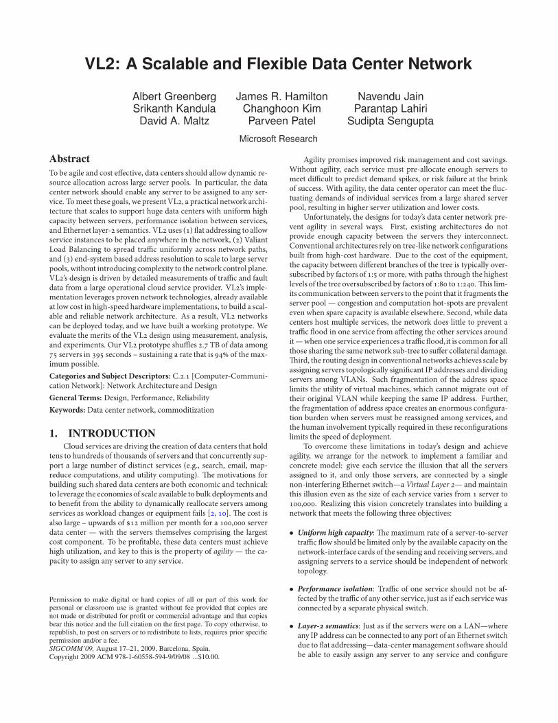
Figure : Mice are numerous; of 'ows are smaller than MB. However, more than of bytes are in 'ows betweenMB and GB.
Our measurement studies found two key results with implica-tions for the network design. First, the tra%c patterns inside a datacenter are highly divergent (as even over representative tra%cmatrices only loosely cover the actual tra%cmatrices seen),and theychange rapidly andunpredictably. Second, the hierarchical topologyis intrinsically unreliable—even with huge e!ort and expense to in-crease the reliability of the network devices close to the top of thehierarchy, we still see failures on those devices resulting in signi.-cant downtimes.
3.1 Data-Center Traffic AnalysisAnalysis of Net$ow and SNMP data from our data centers re-
veals several macroscopic trends. First, the ratio of tra%c volumebetween servers in our data centers to tra%c entering/leaving ourdata centers is currently around : (excluding CDN applications).Second, data-center computation is focused where high speed ac-cess to data on memory or disk is fast and cheap. Although datais distributed across multiple data centers, intense computation andcommunication on data does not straddle data centers due to thecost of long-haul links. -ird, the demand for bandwidth betweenservers inside a data center is growing faster than the demand forbandwidth to external hosts. Fourth, the network is a bottleneckto computation. We frequently see ToR switches whose uplinks areabove utilization.
To uncover the exact nature of tra%c inside a data center, weinstrumented a highly utilized , node cluster in a data centerthat supports data mining on petabytes of data. -e servers aredistributed roughly evenly across ToR switches, which are con-nected hierarchically as shown in Figure .We collected socket-levelevent logs from all machines over two months.
3.2 Flow Distribution AnalysisDistribution of 'ow sizes: Figure illustrates the nature of
$ows within the monitored data center. -e $ow size statistics(marked as ‘+’s) show that the majority of $ows are small (a fewKB); most of these small $ows are hellos and meta-data requests tothe distributed .le system. To examine longer $ows, we compute astatistic termed total bytes (marked as ‘o’s) by weighting each $owsize by its number of bytes. Total bytes tells us, for a random byte,the distribution of the $ow size it belongs to. Almost all the bytesin the data center are transported in $ows whose lengths vary fromabout MB to about GB.-e mode at around MB springsfrom the fact that the distributed .le system breaks long .les into-MB size chunks. Importantly, $ows over a few GB are rare.
0
0.01
0.02
0.03
0.04
1 10 100 1000 0
0.2
0.4
0.6
0.8
1
Fra
ctio
n o
f T
ime
Cum
ula
tive
Number of Concurrent flows in/out of each Machine
PDFCDF
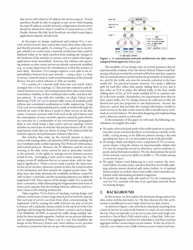
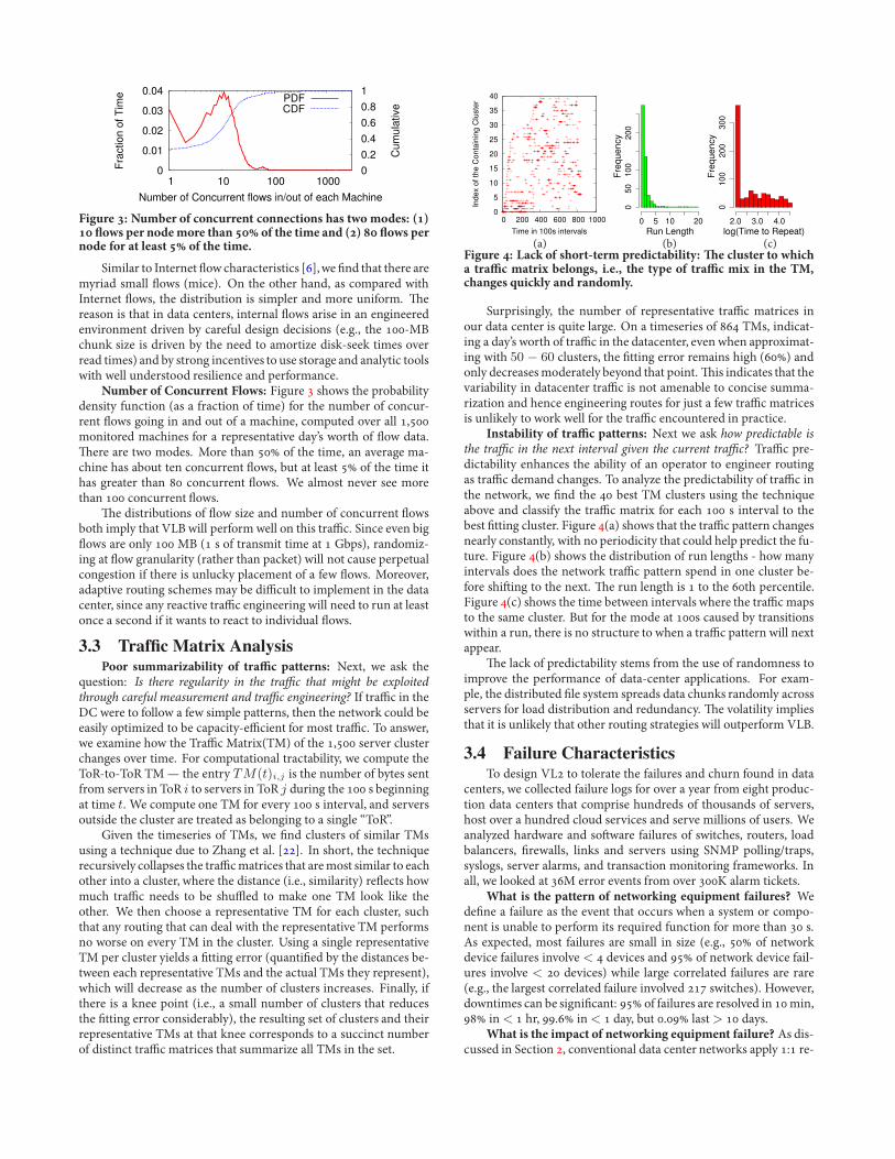
Figure : Number of concurrent connections has two modes: () 'ows per nodemore than of the time and () 'ows pernode for at least of the time.
Similar to Internet $ow characteristics [],we .nd that there aremyriad small $ows (mice). On the other hand, as compared withInternet $ows, the distribution is simpler and more uniform. -ereason is that in data centers, internal $ows arise in an engineeredenvironment driven by careful design decisions (e.g., the -MBchunk size is driven by the need to amortize disk-seek times overread times) and by strong incentives to use storage and analytic toolswith well understood resilience and performance.
Number of Concurrent Flows: Figure shows the probabilitydensity function (as a fraction of time) for the number of concur-rent $ows going in and out of a machine, computed over all ,monitored machines for a representative day’s worth of $ow data.-ere are two modes. More than of the time, an average ma-chine has about ten concurrent $ows, but at least of the time ithas greater than concurrent $ows. We almost never see morethan concurrent $ows.
-e distributions of $ow size and number of concurrent $owsboth imply that VLB will perform well on this tra%c. Since even big$ows are only MB ( s of transmit time at Gbps), randomiz-ing at $ow granularity (rather than packet) will not cause perpetualcongestion if there is unlucky placement of a few $ows. Moreover,adaptive routing schemes may be di%cult to implement in the datacenter, since any reactive tra%c engineering will need to run at leastonce a second if it wants to react to individual $ows.
3.3 Traffic Matrix AnalysisPoor summarizability of tra+c patterns: Next, we ask the
question: Is there regularity in the tra#c that might be exploitedthrough careful measurement and tra#c engineering? If tra%c in theDC were to follow a few simple patterns, then the network could beeasily optimized to be capacity-e%cient for most tra%c. To answer,we examine how the Tra%c Matrix(TM) of the , server clusterchanges over time. For computational tractability, we compute theToR-to-ToR TM— the entry TM(t)i,j is the number of bytes sentfrom servers in ToR i to servers in ToR j during the s beginningat time t. We compute one TM for every s interval, and serversoutside the cluster are treated as belonging to a single “ToR”.
Given the timeseries of TMs, we .nd clusters of similar TMsusing a technique due to Zhang et al. []. In short, the techniquerecursively collapses the tra%cmatrices that aremost similar to eachother into a cluster, where the distance (i.e., similarity) re$ects howmuch tra%c needs to be shu'ed to make one TM look like theother. We then choose a representative TM for each cluster, suchthat any routing that can deal with the representative TM performsno worse on every TM in the cluster. Using a single representativeTM per cluster yields a .tting error (quanti.ed by the distances be-tween each representative TMs and the actual TMs they represent),which will decrease as the number of clusters increases. Finally, ifthere is a knee point (i.e., a small number of clusters that reducesthe .tting error considerably), the resulting set of clusters and theirrepresentative TMs at that knee corresponds to a succinct numberof distinct tra%c matrices that summarize all TMs in the set.
0
5
10
15
20
25
30
35
40
0 200 400 600 800 1000
Ind
ex
of
the
Co
nta
inin
g C
lust
er
Time in 100s intervals
Fre
qu
en
cy
0 5 10 20
05
01
00
20
0
Run Length
Fre
qu
en
cy
2.0 3.0 4.0
01
00
20
03
00
log(Time to Repeat)
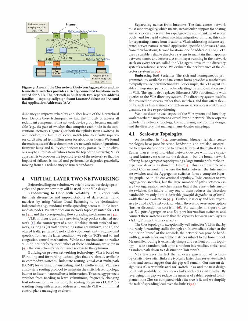
(a) (b) (c)Figure : Lack of short-term predictability: -e cluster to whicha tra+c matrix belongs, i.e., the type of tra+c mix in the TM,changes quickly and randomly.
Surprisingly, the number of representative tra%c matrices inour data center is quite large. On a timeseries of TMs, indicat-ing a day’s worth of tra%c in the datacenter, even when approximat-ing with 50 ! 60 clusters, the .tting error remains high () andonly decreasesmoderately beyond that point.-is indicates that thevariability in datacenter tra%c is not amenable to concise summa-rization and hence engineering routes for just a few tra%c matricesis unlikely to work well for the tra%c encountered in practice.
Instability of tra+c patterns: Next we ask how predictable isthe tra#c in the next interval given the current tra#c? Tra%c pre-dictability enhances the ability of an operator to engineer routingas tra%c demand changes. To analyze the predictability of tra%c inthe network, we .nd the best TM clusters using the techniqueabove and classify the tra%c matrix for each s interval to thebest .tting cluster. Figure (a) shows that the tra%c pattern changesnearly constantly, with no periodicity that could help predict the fu-ture. Figure (b) shows the distribution of run lengths - how manyintervals does the network tra%c pattern spend in one cluster be-fore shi2ing to the next. -e run length is to the th percentile.Figure (c) shows the time between intervals where the tra%c mapsto the same cluster. But for the mode at s caused by transitionswithin a run, there is no structure to when a tra%c pattern will nextappear.
-e lack of predictability stems from the use of randomness toimprove the performance of data-center applications. For exam-ple, the distributed .le system spreads data chunks randomly acrossservers for load distribution and redundancy. -e volatility impliesthat it is unlikely that other routing strategies will outperform VLB.
3.4 Failure CharacteristicsTo design VL to tolerate the failures and churn found in data
centers, we collected failure logs for over a year from eight produc-tion data centers that comprise hundreds of thousands of servers,host over a hundred cloud services and serve millions of users. Weanalyzed hardware and so2ware failures of switches, routers, loadbalancers, .rewalls, links and servers using SNMP polling/traps,syslogs, server alarms, and transaction monitoring frameworks. Inall, we looked at M error events from over K alarm tickets.
What is the pattern of networking equipment failures? Wede.ne a failure as the event that occurs when a system or compo-nent is unable to perform its required function for more than s.As expected, most failures are small in size (e.g., of networkdevice failures involve < devices and of network device fail-ures involve < devices) while large correlated failures are rare(e.g., the largest correlated failure involved switches). However,downtimes can be signi.cant: of failures are resolved in min, in < hr, . in < day, but . last > days.
What is the impact of networking equipment failure? As dis-cussed in Section , conventional data center networks apply : re-
. . .
. . .
!"#
$%&
. . .
. . . .
'(()
DA/2 x 10G
DA/2 x 10G
DI x10G
2 x10G DADI/4 x ToR Switches
DI x Aggregate Switches
20(DADI/4) x Servers
InternetLink-state networkcarrying only LAs
(e.g., 10/8) DA/2 x Intermediate Switches
Fungible pool ofservers owning AAs
(e.g., 20/8)
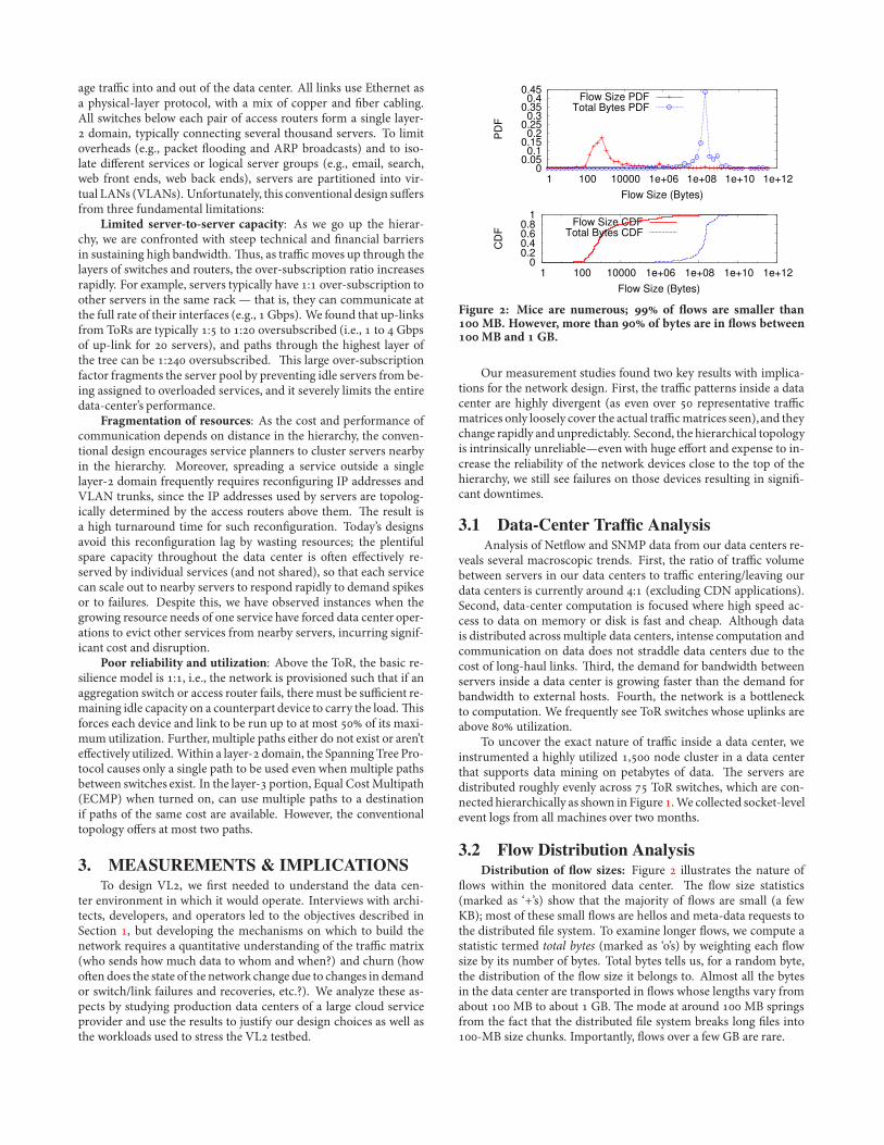
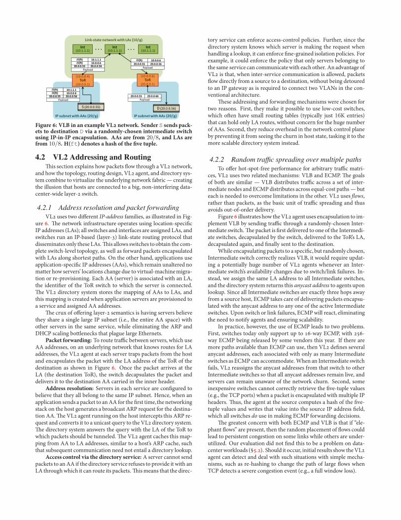
Figure : An exampleClos network betweenAggregation and In-termediate switches provides a richly-connected backbone well-suited for VLB. -e network is built with two separate addressfamilies— topologically signi"cant LocatorAddresses (LAs) and'at Application Addresses (AAs).
dundancy to improve reliability at higher layers of the hierarchicaltree. Despite these techniques, we .nd that in . of failures allredundant components in a network device group became unavail-able (e.g., the pair of switches that comprise each node in the con-ventional network (Figure ) or both the uplinks from a switch). Inone incident, the failure of a core switch (due to a faulty supervi-sor card) a!ected ten million users for about four hours. We foundthe main causes of these downtimes are networkmiscon.gurations,.rmware bugs, and faulty components (e.g., ports). With no obvi-ous way to eliminate all failures from the top of the hierarchy, VL’sapproach is to broaden the topmost levels of the network so that theimpact of failures is muted and performance degrades gracefully,moving from : redundancy to n:m redundancy.
4. VIRTUAL LAYER TWO NETWORKINGBefore detailing our solution, we brie$ydiscuss our design prin-
ciples and preview how they will be used in the VL design.Randomizing to Cope with Volatility: VL copes with
the high divergence and unpredictability of data-center tra%cmatrices by using Valiant Load Balancing to do destination-independent (e.g., random) tra%c spreading across multiple inter-mediate nodes. We introduce our network topology suited for VLBin §., and the corresponding $ow spreading mechanism in §..
VLB, in theory, ensures a non-interfering packet switched net-work [], the counterpart of a non-blocking circuit switched net-work, as long as (a) tra%c spreading ratios are uniform, and (b) theo!ered tra%c patterns do not violate edge constraints (i.e., line cardspeeds). To meet the latter condition, we rely on TCP’s end-to-endcongestion control mechanism. While our mechanisms to realizeVLB do not perfectly meet either of these conditions, we show in§. that our scheme’s performance is close to the optimum.
Building on proven networking technology: VL is based onIP routing and forwarding technologies that are already availablein commodity switches: link-state routing, equal-cost multi-path(ECMP) forwarding, IP anycasting, and IP multicasting. VL usesa link-state routing protocol to maintain the switch-level topology,but not to disseminate endhosts’ information.-is strategyprotectsswitches from needing to learn voluminous, frequently-changinghost information. Furthermore, the routing design uses ECMP for-warding along with anycast addresses to enable VLB with minimalcontrol plane messaging or churn.
Separating names from locators: -e data center networkmust support agility, whichmeans, in particular, support for hostingany service on any server, for rapid growing and shrinking of serverpools, and for rapid virtual machine migration. In turn, this callsfor separating names from locations. VL’s addressing scheme sep-arates server names, termed application-speci.c addresses (AAs),from their locations, termed location-speci.c addresses (LAs). VLuses a scalable, reliable directory system to maintain the mappingsbetween names and locators. A shim layer running in the networkstack on every server, called the VL agent, invokes the directorysystem’s resolution service. We evaluate the performance of the di-rectory system in §..
Embracing End Systems: -e rich and homogeneous pro-grammability available at data-center hosts provides a mechanismto rapidly realize new functionality. For example, the VL agent en-ables .ne-grained path control by adjusting the randomization usedin VLB. -e agent also replaces Ethernet’s ARP functionality withqueries to the VL directory system. -e directory system itself isalso realized on servers, rather than switches, and thus o!ers $exi-bility, such as .ne-grained, context-aware server access control anddynamic service re-provisioning.
We next describe each aspect of the VL system and how theywork together to implement a virtual layer- network.-ese aspectsinclude the network topology, the addressing and routing design,and the directory that manages name-locator mappings.
4.1 Scale-out TopologiesAs described in §., conventional hierarchical data-center
topologies have poor bisection bandwidth and are also suscepti-ble to major disruptions due to device failures at the highest levels.Rather than scale up individual network devices with more capac-ity and features, we scale out the devices — build a broad networko!ering huge aggregate capacity using a large number of simple, in-expensive devices, as shown in Figure . -is is an example of afolded Clos network [] where the links between the Intermedi-ate switches and the Aggregation switches form a complete bipar-tite graph. As in the conventional topology, ToRs connect to twoAggregation switches, but the large number of paths between ev-ery two Aggregation switches means that if there are n Intermedi-ate switches, the failure of any one of them reduces the bisectionbandwidth by only 1/n–a desirable graceful degradation of band-width that we evaluate in §.. Further, it is easy and less expen-sive to build a Clos network for which there is no over-subscription(further discussion on cost is in §). For example, in Figure , weuse DA-port Aggregation and DI -port Intermediate switches, andconnect these switches such that the capacity between each layer isDIDA/2 times the link capacity.
-e Clos topology is exceptionally well suited for VLB in that byindirectly forwarding tra%c through an Intermediate switch at thetop tier or “spine” of the network, the network can provide band-width guarantees for any tra%c matrices subject to the hose model.Meanwhile, routing is extremely simple and resilient on this topol-ogy — take a random path up to a random intermediate switch anda random path down to a destination ToR switch.
VL leverages the fact that at every generation of technol-ogy, switch-to-switch links are typically faster than server-to-switchlinks, and trends suggest that this gap will remain. Our current de-sign uses G server links and G switch links, and the next designpoint will probably be G server links with G switch links. Byleveraging this gap, we reduce the number of cables required to im-plement the Clos (as compared with a fat-tree []), and we simplifythe task of spreading load over the links (§.).
!"#$%&'()#*+),#--$#./0123
4+'56$)7)(#'()*895#*+),#4-$#.:0123
!"#$%&'()#*+),#--$#./0123
!"!"#$#$#$%%&
!')!'#$'$'$'&
#"!"#$#$#$%(&
!"#$%"&
!"#"#"#$$ !"#"#"#$%H&'() *"#"#"#%
H&'() *"#*#*#*
!"#$%"&
!"#"#"#$$ !"#"#"#%%
!'#$#$#$(&
;8<!"#$#$#$'&
!'#$#$#$)&
;8<!"#$#$#$'&
!')!'#$'$'$'&
!')!'#$'$'$'&
. . . . . .
!"#$%"&
!"#"#"#$$ !"#"#"#$%H&'() *"#"#"#%
H&'() *"#*#*#*
!"#$%"&
!"#"#"#$$ !"#"#"#$%
H&'() *"#"#"#%
Figure : VLB in an example VL network. Sender S sends pack-ets to destination D via a randomly-chosen intermediate switchusing IP-in-IP encapsulation. AAs are from 20/8, and LAs arefrom 10/8. H(ft) denotes a hash of the "ve tuple.
4.2 VL2 Addressing and Routing-is section explains how packets $ow through a VL network,
and how the topology, routing design, VL agent, and directory sys-tem combine to virtualize the underlying network fabric— creatingthe illusion that hosts are connected to a big, non-interfering data-center-wide layer- switch.
4.2.1 Address resolution and packet forwardingVL uses two di!erent IP-address families, as illustrated in Fig-
ure . -e network infrastructure operates using location-speci.cIP addresses (LAs); all switches and interfaces are assigned LAs, andswitches run an IP-based (layer-) link-state routing protocol thatdisseminates only these LAs.-is allows switches to obtain the com-plete switch-level topology, as well as forward packets encapsulatedwith LAs along shortest paths. On the other hand, applications useapplication-speci.c IP addresses (AAs), which remain unaltered nomatter how servers’ locations change due to virtual-machinemigra-tion or re-provisioning. Each AA (server) is associated with an LA,the identi.er of the ToR switch to which the server is connected.-e VL directory system stores the mapping of AAs to LAs, andthis mapping is created when application servers are provisioned toa service and assigned AA addresses.
-e crux of o!ering layer- semantics is having servers believethey share a single large IP subnet (i.e., the entire AA space) withother servers in the same service, while eliminating the ARP andDHCP scaling bottlenecks that plague large Ethernets.
Packet forwarding: To route tra%c between servers, which useAA addresses, on an underlying network that knows routes for LAaddresses, the VL agent at each server traps packets from the hostand encapsulates the packet with the LA address of the ToR of thedestination as shown in Figure . Once the packet arrives at theLA (the destination ToR), the switch decapsulates the packet anddelivers it to the destination AA carried in the inner header.
Address resolution: Servers in each service are con.gured tobelieve that they all belong to the same IP subnet. Hence, when anapplication sends a packet to anAA for the .rst time,the networkingstack on the host generates a broadcast ARP request for the destina-tion AA.-e VL agent running on the host intercepts this ARP re-quest and converts it to a unicast query to the VL directory system.-e directory system answers the query with the LA of the ToR towhich packets should be tunneled.-e VL agent caches this map-ping from AA to LA addresses, similar to a host’s ARP cache, suchthat subsequent communication need not entail a directory lookup.
Access control via the directory service: A server cannot sendpackets to anAA if the directory service refuses to provide it with anLA throughwhich it can route its packets.-ismeans that the direc-
tory service can enforce access-control policies. Further, since thedirectory system knows which server is making the request whenhandling a lookup, it can enforce .ne-grained isolation policies. Forexample, it could enforce the policy that only servers belonging tothe same service can communicatewith each other. An advantage ofVL is that, when inter-service communication is allowed, packets$ow directly from a source to a destination, without being detouredto an IP gateway as is required to connect two VLANs in the con-ventional architecture.
-ese addressing and forwarding mechanisms were chosen fortwo reasons. First, they make it possible to use low-cost switches,which o2en have small routing tables (typically just 16K entries)that can hold only LA routes, without concern for the huge numberof AAs. Second, they reduce overhead in the network control planeby preventing it from seeing the churn in host state, tasking it to themore scalable directory system instead.
4.2.2 Random traffic spreading over multiple pathsTo o!er hot-spot-free performance for arbitrary tra%c matri-
ces, VL uses two related mechanisms: VLB and ECMP. -e goalsof both are similar — VLB distributes tra%c across a set of inter-mediate nodes and ECMP distributes across equal-cost paths — buteach is needed to overcome limitations in the other. VL uses "ows,rather than packets, as the basic unit of tra%c spreading and thusavoids out-of-order delivery.
Figure illustrates how theVL agent uses encapsulation to im-plement VLB by sending tra%c through a randomly-chosen Inter-mediate switch.-e packet is .rst delivered to one of the Intermedi-ate switches, decapsulated by the switch, delivered to the ToR’s LA,decapsulated again, and .nally sent to the destination.
While encapsulating packets to a speci.c, but randomly chosen,Intermediate switch correctly realizes VLB, it would require updat-ing a potentially huge number of VL agents whenever an Inter-mediate switch’s availability changes due to switch/link failures. In-stead, we assign the same LA address to all Intermediate switches,and the directory system returns this anycast address to agents uponlookup. Since all Intermediate switches are exactly three hops awayfrom a source host, ECMP takes care of delivering packets encapsu-lated with the anycast address to any one of the active Intermediateswitches. Upon switch or link failures, ECMPwill react, eliminatingthe need to notify agents and ensuring scalability.
In practice, however, the use of ECMP leads to two problems.First, switches today only support up to -way ECMP, with -way ECMP being released by some vendors this year. If there aremore paths available than ECMP can use, then VL de.nes severalanycast addresses, each associated with only as many Intermediateswitches as ECMP can accommodate. When an Intermediate switchfails, VL reassigns the anycast addresses from that switch to otherIntermediate switches so that all anycast addresses remain live, andservers can remain unaware of the network churn. Second, someinexpensive switches cannot correctly retrieve the .ve-tuple values(e.g., the TCP ports) when a packet is encapsulatedwith multiple IPheaders. -us, the agent at the source computes a hash of the .ve-tuple values and writes that value into the source IP address .eld,which all switches do use in making ECMP forwarding decisions.
-e greatest concern with both ECMP and VLB is that if “ele-phant $ows” are present, then the random placement of $ows couldlead to persistent congestion on some links while others are under-utilized. Our evaluation did not .nd this to be a problem on data-centerworkloads (§.). Should it occur, initial results show theVLagent can detect and deal with such situations with simple mecha-nisms, such as re-hashing to change the path of large $ows whenTCP detects a severe congestion event (e.g., a full window loss).
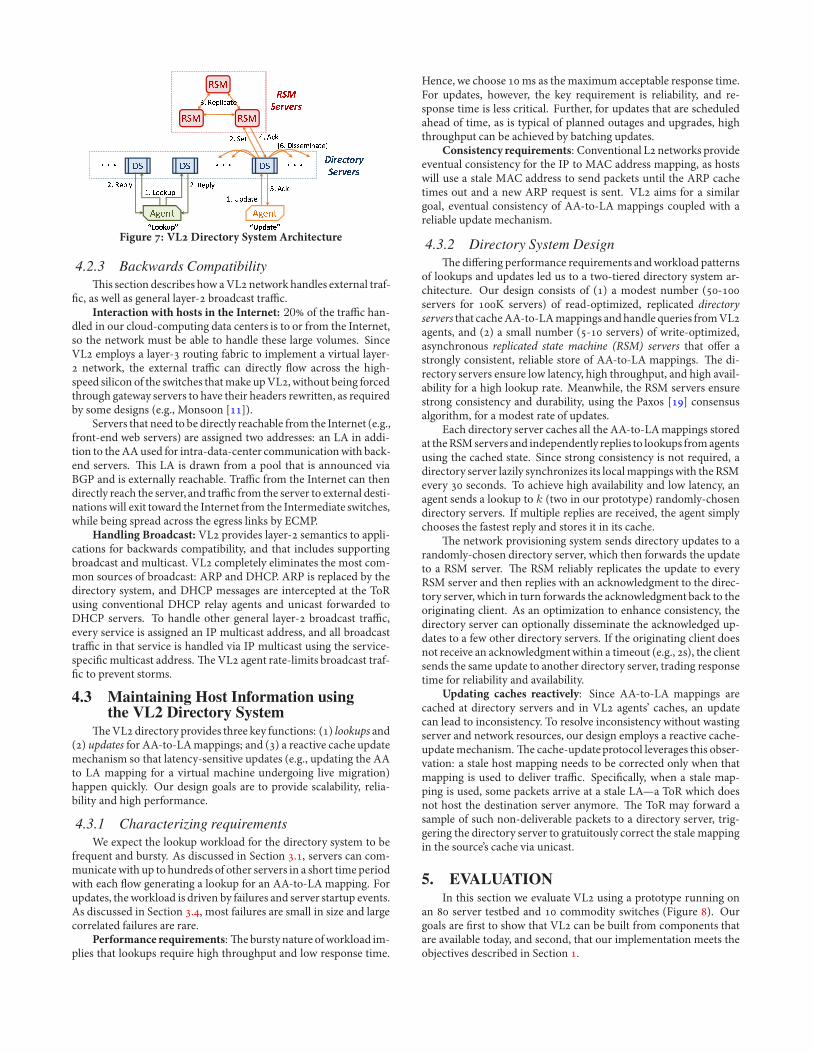
Figure : VLDirectory SystemArchitecture
4.2.3 Backwards Compatibility-is section describes how aVLnetwork handles external traf-
.c, as well as general layer- broadcast tra%c.Interaction with hosts in the Internet: 20 of the tra%c han-
dled in our cloud-computing data centers is to or from the Internet,so the network must be able to handle these large volumes. SinceVL employs a layer- routing fabric to implement a virtual layer- network, the external tra%c can directly $ow across the high-speed silicon of the switches thatmake upVL, without being forcedthrough gateway servers to have their headers rewritten, as requiredby some designs (e.g., Monsoon []).
Servers that need to be directly reachable from the Internet (e.g.,front-end web servers) are assigned two addresses: an LA in addi-tion to theAAused for intra-data-center communicationwith back-end servers. -is LA is drawn from a pool that is announced viaBGP and is externally reachable. Tra%c from the Internet can thendirectly reach the server, and tra%c from the server to external desti-nations will exit toward the Internet from the Intermediate switches,while being spread across the egress links by ECMP.
Handling Broadcast: VL provides layer- semantics to appli-cations for backwards compatibility, and that includes supportingbroadcast and multicast. VL completely eliminates the most com-mon sources of broadcast: ARP and DHCP. ARP is replaced by thedirectory system, and DHCP messages are intercepted at the ToRusing conventional DHCP relay agents and unicast forwarded toDHCP servers. To handle other general layer- broadcast tra%c,every service is assigned an IP multicast address, and all broadcasttra%c in that service is handled via IP multicast using the service-speci.c multicast address. -e VL agent rate-limits broadcast traf-.c to prevent storms.
4.3 Maintaining Host Information usingthe VL2 Directory System
-eVLdirectory provides three key functions: () lookups and() updates for AA-to-LAmappings; and () a reactive cache updatemechanism so that latency-sensitive updates (e.g., updating the AAto LA mapping for a virtual machine undergoing live migration)happen quickly. Our design goals are to provide scalability, relia-bility and high performance.
4.3.1 Characterizing requirementsWe expect the lookup workload for the directory system to be
frequent and bursty. As discussed in Section ., servers can com-municate with up to hundreds of other servers in a short time periodwith each $ow generating a lookup for an AA-to-LA mapping. Forupdates, the workload is driven by failures and server startup events.As discussed in Section ., most failures are small in size and largecorrelated failures are rare.
Performance requirements:-e bursty nature ofworkload im-plies that lookups require high throughput and low response time.
Hence, we choose ms as the maximum acceptable response time.For updates, however, the key requirement is reliability, and re-sponse time is less critical. Further, for updates that are scheduledahead of time, as is typical of planned outages and upgrades, highthroughput can be achieved by batching updates.
Consistency requirements: Conventional Lnetworks provideeventual consistency for the IP to MAC address mapping, as hostswill use a stale MAC address to send packets until the ARP cachetimes out and a new ARP request is sent. VL aims for a similargoal, eventual consistency of AA-to-LA mappings coupled with areliable update mechanism.
4.3.2 Directory System Design-e di!ering performance requirements andworkload patterns
of lookups and updates led us to a two-tiered directory system ar-chitecture. Our design consists of () a modest number (-servers for K servers) of read-optimized, replicated directoryservers that cacheAA-to-LAmappings andhandle queries fromVLagents, and () a small number (- servers) of write-optimized,asynchronous replicated state machine (RSM) servers that o!er astrongly consistent, reliable store of AA-to-LA mappings. -e di-rectory servers ensure low latency, high throughput, and high avail-ability for a high lookup rate. Meanwhile, the RSM servers ensurestrong consistency and durability, using the Paxos [] consensusalgorithm, for a modest rate of updates.
Each directory server caches all the AA-to-LAmappings storedat theRSMservers and independently replies to lookups fromagentsusing the cached state. Since strong consistency is not required, adirectory server lazily synchronizes its localmappingswith the RSMevery seconds. To achieve high availability and low latency, anagent sends a lookup to k (two in our prototype) randomly-chosendirectory servers. If multiple replies are received, the agent simplychooses the fastest reply and stores it in its cache.
-e network provisioning system sends directory updates to arandomly-chosen directory server, which then forwards the updateto a RSM server. -e RSM reliably replicates the update to everyRSM server and then replies with an acknowledgment to the direc-tory server, which in turn forwards the acknowledgment back to theoriginating client. As an optimization to enhance consistency, thedirectory server can optionally disseminate the acknowledged up-dates to a few other directory servers. If the originating client doesnot receive an acknowledgmentwithin a timeout (e.g., s), the clientsends the same update to another directory server, trading responsetime for reliability and availability.
Updating caches reactively: Since AA-to-LA mappings arecached at directory servers and in VL agents’ caches, an updatecan lead to inconsistency. To resolve inconsistency without wastingserver and network resources, our design employs a reactive cache-updatemechanism.-e cache-updateprotocol leverages this obser-vation: a stale host mapping needs to be corrected only when thatmapping is used to deliver tra%c. Speci.cally, when a stale map-ping is used, some packets arrive at a stale LA—a ToR which doesnot host the destination server anymore. -e ToR may forward asample of such non-deliverable packets to a directory server, trig-gering the directory server to gratuitously correct the stale mappingin the source’s cache via unicast.
5. EVALUATIONIn this section we evaluate VL using a prototype running on
an server testbed and commodity switches (Figure ). Ourgoals are .rst to show that VL can be built from components thatare available today, and second, that our implementation meets theobjectives described in Section .
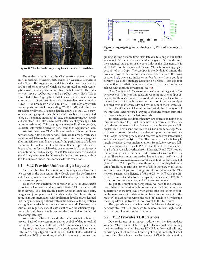
Figure : VL testbed comprising servers and switches.
-e testbed is built using the Clos network topology of Fig-ure , consisting of Intermediate switches, Aggregation switchesand ToRs. -e Aggregation and Intermediate switches have Gbps Ethernet ports, of which ports are used on each Aggre-gation switch and ports on each Intermediate switch. -e ToRsswitches have Gbps ports and Gbps ports. Each ToR isconnected to two Aggregation switches via Gbps links, and to servers via Gbps links. Internally, the switches use commodityASICs — the Broadcom and — although any switchthat supports line rate L forwarding, OSPF, ECMP, and IPinIP de-capsulation will work. To enable detailed analysis of the TCP behav-ior seen during experiments, the servers’ kernels are instrumentedto log TCP extended statistics [] (e.g., congestion window (cwnd)and smoothed RTT) a2er each socket bu!er is sent (typically KBin our experiments). -is logging only marginally a!ects goodput,i.e., useful information delivered per second to the application layer.
We .rst investigate VL’s ability to provide high and uniformnetwork bandwidth between servers.-en, we analyze performanceisolation and fairness between tra%c $ows, measure convergencea2er link failures, and .nally, quantify the performance of addressresolution. Overall, our evaluation shows that VL provides an ef-fective substrate for a scalable data center network; VL achieves () optimal network capacity, () a TCP fairness index of ., ()graceful degradation under failures with fast reconvergence, and ()K lookups/sec under ms for fast address resolution.
5.1 VL2 Provides Uniform High CapacityAcentral objective ofVL is uniformhigh capacity between any
two servers in the data center. How closely does the performanceand e%ciency of a VL network match that of a Layer switch with: over-subscription?
To answer this question, we consider an all-to-all data shu$estress test: all servers simultaneously initiate TCP transfers to allother servers. -is data shu'e pattern arises in large scale sorts,merges and join operations in the data center. We chose this testbecause, in our interactionswith application developers, we learnedthat many use such operations with caution, because the operationsare highly expensive in today’s data center network. However, datashu'es are required, and, if data shu'es can be e%ciently sup-ported, it could have large impact on the overall algorithmic anddata storage strategy.
We create an all-to-all data shu'e tra%c matrix involving servers. Each of servers must deliver MB of data to each ofthe other servers - a shu'e of . TB from memory to memory.
Figure shows how the sum of the goodput over all $ows varieswith time during a typical run of the . TB data shu'e. All data iscarried over TCP connections, all of which attempt to connect be-
0 50 100 150 200 250 300 350 4000
10
20
30
40
50
60
Time (s)
Aggre
gate
goodput (G
bps)
0 50 100 150 200 250 300 350 4000
1000
2000
3000
4000
5000
6000
Act
ive flo
ws
Aggregate goodput
Active flows
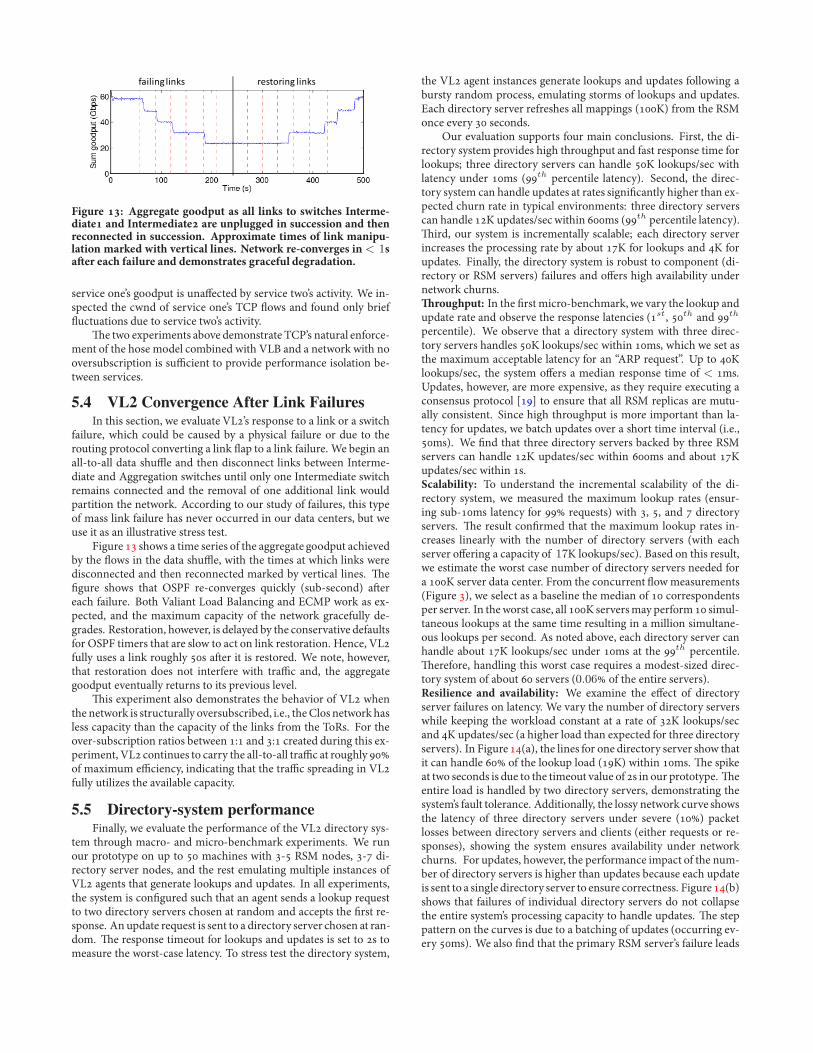
Figure : Aggregate goodput during a .TB shu0e among servers.
ginning at time (some $ows start late due to a bug in our tra%cgenerator). VL completes the shu'e in s. During the run,the sustained utilization of the core links in the Clos network isabout . For the majority of the run, VL achieves an aggregategoodput of . Gbps. -e goodput is evenly divided among the$ows for most of the run, with a fairness index between the $owsof . [], where . indicates perfect fairness (mean goodputper $ow . Mbps, standard deviation . Mbps). -is goodputis more than x what the network in our current data centers canachieve with the same investment (see §).
How close is VL to the maximum achievable throughput in thisenvironment? To answer this question, we compute the goodput ef-.ciency for this data transfer. -e goodput e%ciency of the networkfor any interval of time is de.ned as the ratio of the sent goodputsummed over all interfaces divided by the sum of the interface ca-pacities. An e%ciency of 1 would mean that all the capacity on allthe interfaces is entirely used carrying useful bytes from the time the.rst $ow starts to when the last $ow ends.
To calculate the goodput e%ciency, two sources of ine%ciencymust be accounted for. First, to achieve a performance e%ciencyof 1, the server network interface cards must be completely full-duplex: able to both send and receive Gbps simultaneously. Mea-surements show our interfaces are able to support a sustained rateof . Gbps (summing the sent and received capacity), introducingan ine%ciency of 1 !
1.82
= 10%. -e source of this ine%ciency islargely the device driver implementation. Second, for every two full-size data packets there is a TCP ACK, and these three frames have B of unavoidable overhead from Ethernet, IP and TCP headersfor every B sent over the network.-is results in an ine%ciencyof . -erefore, our current testbed has an intrinsic ine%ciency of resulting in a maximum achievable goodput for our testbed of(75".83) = 62.3Gbps. Wederive this number by noting that everyunit of tra%c has to sink at a server, of which there are instancesand each has a Gbps link. Taking this into consideration, the VLnetwork sustains an e%ciency of 58.8/62.3 = 94% with the dif-ference from perfect due to the encapsulation headers (.), TCPcongestion control dynamics, and TCP retransmissions.
To put this number in perspective, we note that a conven-tional hierarchical design with servers per rack and : over-subscription at the .rst level switch would take x longer to shuf-$e the same amount of data as tra%c from each server not in therack () to each server within the rack () needs to $ow throughthe Gbps downlink from .rst level switch to the ToR switch.
-e e%ciency combined with the fairness index of .demonstrates that VL promises to achieve uniform high band-width across all servers in the data center.
5.2 VL2 Provides VLB FairnessDue to its use of an anycast address on the intermediate
switches, VL relies on ECMP to split tra%c in equal ratios amongthe intermediate switches. Because ECMP does $ow-level splitting,coexisting elephant and mice $ows might be split unevenly at smalltime scales. To evaluate the e!ectiveness of VL’s implementation

0 100 200 300 400 500 6000.9
0.92
0.94
0.96
0.98
1
1.02
Time (s)
Fairness
Agg1
Agg2
Agg3
Figure : Fairness measures how evenly 'ows are split to inter-mediate switches from aggregation switches.
of Valiant Load Balancing in splitting tra%c evenly across the net-work, we created an experiment on our -node testbed with tra%ccharacteristics extracted from the DC workload of Section . Eachserver initially picks a value from the distribution of number of con-current $ows and maintains this number of $ows throughout theexperiment. At the start, or a2er a $ow completes, it picks a new$ow size from the associated distribution and starts the $ow(s). Be-cause all $ows pass through the Aggregation switches, it is su%cientto check at each Aggregation switch for the split ratio among thelinks to the Intermediate switches. We do so by collecting SNMPcounters at second intervals for all links from Aggregation to In-termediate switches.
Before proceeding further, we note that, unlike the e%ciencyexperiment above, the tra%c mix here is indicative of actual datacenter workload. Wemimic the $ow size distribution and the num-ber of concurrent $ows observed by measurements in §.
In Figure , for each Aggregation switch, we plot Jain’s fair-ness index [] for the tra%c to Intermediate switches as a time se-ries. -e average utilization of links was between and . Asshown in the .gure, the VLB split ratio fairness index averagesmorethan . for all Aggregation switches over the duration of this ex-periment. VL achieves such high fairness because there are enough$ows at the Aggregation switches that randomization bene.ts fromstatistical multiplexing. -is evaluation validates that our imple-mentation ofVLB is an e!ectivemechanism for preventing hot spotsin a data center network.
Our randomization-based tra%c splitting in Valiant Load Bal-ancing takes advantage of the 10x gap in speed between server linecards and core network links. If the core network were built out oflinks with the same speed as the server line cards, then only one full-rate $ow will .t on each link, and the spreading of $ows has to beperfect in order to prevent two long-lived $ows from traversing thesame link and causing congestion. However, splitting at a sub-$owgranularity (for example, $owlet switching []) might alleviate thisproblem.
5.3 VL2 Provides Performance IsolationOne of the primary objectives of VL is agility, which we de.ne
as the ability to assign any server, anywhere in the data center, to anyservice (§). Achieving agility critically depends on providing suf-.cient performance isolation between services so that if one servicecomes under attack or a bug causes it to spray packets, it does notadversely impact the performance of other services.
Performance isolation in VL rests on the mathematics of VLB— that any tra%cmatrix that obeys the hosemodel is routed by split-ting to intermediate nodes in equal ratios (through randomization)to prevent any persistent hot spots. Rather than have VL performadmission control or rate shaping to ensure the tra%c o!ered to thenetwork conforms to the hose model, we instead rely on TCP to en-sure that each $ow o!ered to the network is rate-limited to its fairshare of its bottleneck.
60 80 100 120 140 160 180 200 2200
5
10
15
Aggre
gate
goodput (G
bps)
Time (s)
Service 1
Service 2
Figure : Aggregate goodput of two services with servers inter-mingled on the ToRs. Service one’s goodput is una1ected as ser-vice two ramps tra+c up and down.
50 60 70 80 90 100 110 120 1300
5
10
15
20
Aggre
gate
goodput (G
bps)
Time (s)
50 60 70 80 90 100 110 120 1300
500
1000
1500
2000
# m
ice s
tart
ed
Aggregate goodput
# mice started
Figure : Aggregate goodput of service one as service two cre-ates bursts containing successivelymore short TCP connections.
A key question we need to validate for performance isolation iswhether TCP reacts su%ciently quickly to control the o!ered rateof $ows within services. TCP works with packets and adjusts theirsending rate at the time-scale of RTTs. Conformance to the hosemodel, however, requires instantaneous feedback to avoid over-subscription of tra%c ingress/egress bounds. Our next set of exper-iments shows that TCP is "fast enough" to enforce the hose modelfor tra%c in each service so as to provide the desired performanceisolation across services.
In this experiment, we add two services to the network. -e .rstservice has servers allocated to it and each server starts a singleTCP transfer to one other server at time and these $ows last forthe duration of the experiment. -e second service starts with oneserver at seconds and a new server is assigned to it every sec-onds for a total of servers. Every server in service two starts anGB transfer over TCP as soon as it starts up. Both the services’servers are intermingled among the ToRs to demonstrate agile as-signment of servers.
Figure shows the aggregate goodput of both services as afunction of time. As seen in the .gure, there is no perceptible changeto the aggregate goodput of service one as the $ows in service twostart or complete, demonstrating performance isolation when thetra%c consists of large long-lived $ows. -rough extended TCPstatistics, we inspected the congestion window size (cwnd) of ser-vice one’s TCP $ows, and found that the $ows $uctuate around theirfair share brie$y due to service two’s activity but stabilize quickly.
We would expect that a service sending unlimited rates of UDPtra%c might violate the hose model and hence performance isola-tion. We do not observe such UDP tra%c in our data centers, al-though techniques such as STCP to make UDP “TCP friendly” arewell known if needed []. However, large numbers of short TCPconnections (mice),which are common inDCs (Section ), have thepotential to cause problems similar to UDP as each $ow can trans-mit small bursts of packets during slow start.
To evaluate this aspect, we conduct a second experiment withservice one sending long-lived TCP $ows, as in experiment one.Servers in service two create bursts of short TCP connections ( to KB), each burst containing progressively more connections. Fig-ure shows the aggregate goodput of service one’s $ows along withthe total number of TCP connections created by service two. Again,
!"#$#%&'$#%() *+),-*#%&'$#%()
Figure : Aggregate goodput as all links to switches Interme-diate and Intermediate are unplugged in succession and thenreconnected in succession. Approximate times of link manipu-lation marked with vertical lines. Network re-converges in < 1sa2er each failure and demonstrates graceful degradation.
service one’s goodput is una!ected by service two’s activity. We in-spected the cwnd of service one’s TCP $ows and found only brief$uctuations due to service two’s activity.
-e two experiments above demonstrate TCP’s natural enforce-ment of the hose model combined with VLB and a network with nooversubscription is su%cient to provide performance isolation be-tween services.
5.4 VL2 Convergence After Link FailuresIn this section, we evaluate VL’s response to a link or a switch
failure, which could be caused by a physical failure or due to therouting protocol converting a link $ap to a link failure. We begin anall-to-all data shu'e and then disconnect links between Interme-diate and Aggregation switches until only one Intermediate switchremains connected and the removal of one additional link wouldpartition the network. According to our study of failures, this typeof mass link failure has never occurred in our data centers, but weuse it as an illustrative stress test.
Figure shows a time series of the aggregate goodput achievedby the $ows in the data shu'e, with the times at which links weredisconnected and then reconnected marked by vertical lines. -e.gure shows that OSPF re-converges quickly (sub-second) a2ereach failure. Both Valiant Load Balancing and ECMP work as ex-pected, and the maximum capacity of the network gracefully de-grades. Restoration, however, is delayed by the conservative defaultsfor OSPF timers that are slow to act on link restoration. Hence, VLfully uses a link roughly s a2er it is restored. We note, however,that restoration does not interfere with tra%c and, the aggregategoodput eventually returns to its previous level.
-is experiment also demonstrates the behavior of VL whenthe network is structurally oversubscribed, i.e., the Clos network hasless capacity than the capacity of the links from the ToRs. For theover-subscription ratios between : and : created during this ex-periment, VL continues to carry the all-to-all tra%c at roughly of maximum e%ciency, indicating that the tra%c spreading in VLfully utilizes the available capacity.
5.5 Directory-system performanceFinally, we evaluate the performance of the VL directory sys-
tem through macro- and micro-benchmark experiments. We runour prototype on up to machines with - RSM nodes, - di-rectory server nodes, and the rest emulating multiple instances ofVL agents that generate lookups and updates. In all experiments,the system is con.gured such that an agent sends a lookup requestto two directory servers chosen at random and accepts the .rst re-sponse. An update request is sent to a directory server chosen at ran-dom. -e response timeout for lookups and updates is set to s tomeasure the worst-case latency. To stress test the directory system,
the VL agent instances generate lookups and updates following abursty random process, emulating storms of lookups and updates.Each directory server refreshes all mappings (K) from the RSMonce every seconds.
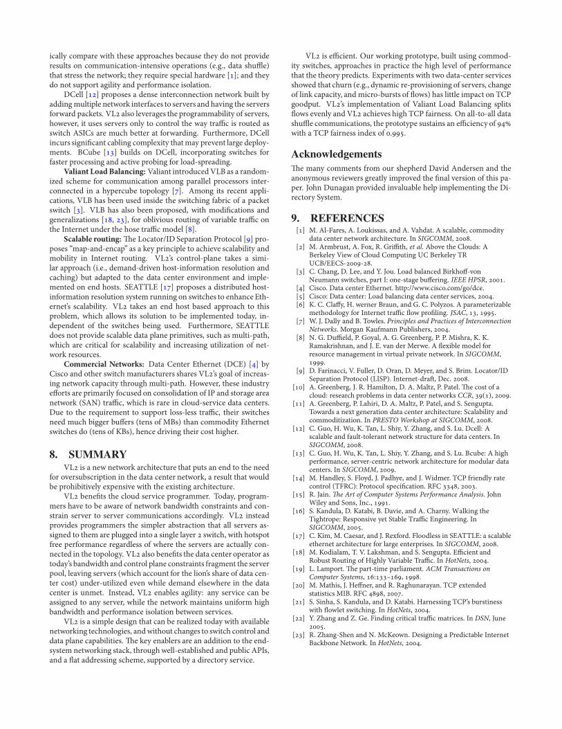
Our evaluation supports four main conclusions. First, the di-rectory system provides high throughput and fast response time forlookups; three directory servers can handle K lookups/sec withlatency under ms (th percentile latency). Second, the direc-tory system can handle updates at rates signi.cantly higher than ex-pected churn rate in typical environments: three directory serverscan handle K updates/sec within ms (th percentile latency).-ird, our system is incrementally scalable; each directory serverincreases the processing rate by about K for lookups and K forupdates. Finally, the directory system is robust to component (di-rectory or RSM servers) failures and o!ers high availability undernetwork churns.-roughput: In the .rst micro-benchmark,we vary the lookup andupdate rate and observe the response latencies (st, th and th
percentile). We observe that a directory system with three direc-tory servers handles K lookups/sec within ms, which we set asthe maximum acceptable latency for an “ARP request”. Up to Klookups/sec, the system o!ers a median response time of < ms.Updates, however, are more expensive, as they require executing aconsensus protocol [] to ensure that all RSM replicas are mutu-ally consistent. Since high throughput is more important than la-tency for updates, we batch updates over a short time interval (i.e.,ms). We .nd that three directory servers backed by three RSMservers can handle K updates/sec within ms and about Kupdates/sec within s.Scalability: To understand the incremental scalability of the di-rectory system, we measured the maximum lookup rates (ensur-ing sub-ms latency for requests) with , , and directoryservers. -e result con.rmed that the maximum lookup rates in-creases linearly with the number of directory servers (with eachserver o!ering a capacity of 17K lookups/sec). Based on this result,we estimate the worst case number of directory servers needed fora K server data center. From the concurrent $owmeasurements(Figure ), we select as a baseline the median of correspondentsper server. In theworst case, all K serversmay perform simul-taneous lookups at the same time resulting in a million simultane-ous lookups per second. As noted above, each directory server canhandle about K lookups/sec under ms at the th percentile.-erefore, handling this worst case requires a modest-sized direc-tory system of about servers (0.06 of the entire servers).Resilience and availability: We examine the e!ect of directoryserver failures on latency. We vary the number of directory serverswhile keeping the workload constant at a rate of K lookups/secand K updates/sec (a higher load than expected for three directoryservers). In Figure (a), the lines for one directory server show thatit can handle of the lookup load (K) within ms. -e spikeat two seconds is due to the timeout value of s in our prototype. -eentire load is handled by two directory servers, demonstrating thesystem’s fault tolerance. Additionally, the lossy network curve showsthe latency of three directory servers under severe () packetlosses between directory servers and clients (either requests or re-sponses), showing the system ensures availability under networkchurns. For updates, however, the performance impact of the num-ber of directory servers is higher than updates because each updateis sent to a single directory server to ensure correctness. Figure (b)shows that failures of individual directory servers do not collapsethe entire system’s processing capacity to handle updates. -e steppattern on the curves is due to a batching of updates (occurring ev-ery ms). We also .nd that the primary RSM server’s failure leads
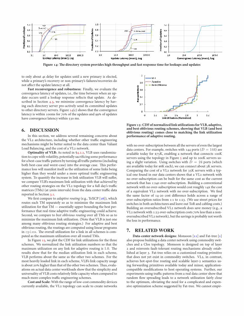
Figure : -e directory system provides high throughput and fast response time for lookups and updates
to only about s delay for updates until a new primary is elected,while a primary’s recovery or non-primary’s failures/recoveries donot a!ect the update latency at all.
Fast reconvergence and robustness: Finally, we evaluate theconvergence latency of updates, i.e., the time between when an up-date occurs until a lookup response re$ects that update. As de-scribed in Section ., we minimize convergence latency by hav-ing each directory server pro-actively send its committed updatesto other directory servers. Figure (c) shows that the convergencelatency is within ms for of the updates and of updateshave convergence latency within ms.
6. DISCUSSIONIn this section, we address several remaining concerns about
the VL architecture, including whether other tra%c engineeringmechanisms might be better suited to the data center than ValiantLoad Balancing, and the cost of a VL network.
Optimality of VLB: As noted in §.., VLB uses randomiza-tion to copewith volatility, potentially sacri.cing some performancefor a best-case tra%c pattern by turning all tra%c patterns (includingboth best-case and worst-case) into the average case. -is perfor-mance loss will manifest itself as the utilization of some links beinghigher than they would under a more optimal tra%c engineeringsystem. To quantify the increase in link utilization VLB will su!er,we compare VLB’s maximum link utilization with that achieved byother routing strategies on the VL topology for a full day’s tra%cmatrices (TMs) (at min intervals) from the data center tra%c datareported in Section ..
We .rst compare to adaptive routing (e.g., TeXCP []), whichroutes each TM separately so as to minimize the maximum linkutilization for that TM — essentially upper-bounding the best per-formance that real-time adaptive tra%c engineering could achieve.Second, we compare to best oblivious routing over all TMs so as tominimize the maximum link utilization. (Note that VLB is just oneamong many oblivious routing strategies.) For adaptive and bestoblivious routing, the routings are computed using linear programsin cplex. -e overall utilization for a link in all schemes is com-puted as the maximum utilization over all routed TMs.
In Figure , we plot the CDF for link utilizations for the threeschemes. We normalized the link utilization numbers so that themaximum utilization on any link for adaptive routing is 1.0. -eresults show that for the median utilization link in each scheme,VLB performs about the same as the other two schemes. For themost heavily loaded link in each scheme, VLB’s link capacity usageis about higher than that of the other two schemes.-us, evalu-ations on actual data center workloads show that the simplicity anduniversality of VLB costs relatively little capacity when compared tomuch more complex tra%c engineering schemes.
Cost and Scale:With the range of low-cost commodity devicescurrently available, the VL topology can scale to create networks
Figure: CDFofnormalized linkutilizations forVLB, adaptive,and best oblivious routing schemes, showing that VLB (and bestoblivious routing) comes close to matching the link utilizationperformance of adaptive routing.
with no over-subscription between all the servers of even the largestdata centers. For example, switches with ports (D = 144) areavailable today for K, enabling a network that connects Kservers using the topology in Figure and up to K servers us-ing a slight variation. Using switches with D = 24 ports (whichare available today for K each), we can connect about K servers.Comparing the cost of a VL network for K servers with a typ-ical one found in our data centers shows that a VL network withno over-subscription can be built for the same cost as the currentnetwork that has : over-subscription. Building a conventionalnetwork with no over-subscription would cost roughly x the costof a equivalent VL network with no over-subscription. We .ndthe same factor of - cost di!erence holds across a range ofover-subscription ratios from : to :. (We use street prices forswitches in both architectures and leave out ToR and cabling costs.)Building an oversubscribed VL network does save money (e.g., aVL networkwith : over-subscription costs less than a non-oversubscribedVL network), but the savings is probably not worththe loss in performance.
7. RELATED WORKData-center network designs: Monsoon [] and Fat-tree []
also propose building a data center network using commodity swit-ches and a Clos topology. Monsoon is designed on top of layer and reinvents fault-tolerant routing mechanisms already estab-lished at layer . Fat-tree relies on a customized routing primitivethat does not yet exist in commodity switches. VL, in contrast,achieves hot-spot-free routing and scalable layer- semantics us-ing forwarding primitives available today and minor, application-compatible modi.cations to host operating systems. Further, ourexperiments using tra%c patterns from a real data center show thatrandom $ow spreading leads to a network utilization fairly closeto the optimum, obviating the need for a complicated and expen-sive optimization scheme suggested by Fat-tree. We cannot empir-
ically compare with these approaches because they do not provideresults on communication-intensive operations (e.g., data shu'e)that stress the network; they require special hardware []; and theydo not support agility and performance isolation.
DCell [] proposes a dense interconnection network built byaddingmultiple network interfaces to servers and having the serversforward packets. VL also leverages the programmability of servers,however, it uses servers only to control the way tra%c is routed asswitch ASICs are much better at forwarding. Furthermore, DCellincurs signi.cant cabling complexity thatmay prevent large deploy-ments. BCube [] builds on DCell, incorporating switches forfaster processing and active probing for load-spreading.
Valiant Load Balancing: Valiant introducedVLB as a random-ized scheme for communication among parallel processors inter-connected in a hypercube topology []. Among its recent appli-cations, VLB has been used inside the switching fabric of a packetswitch []. VLB has also been proposed, with modi.cations andgeneralizations [, ], for oblivious routing of variable tra%c onthe Internet under the hose tra%c model [].
Scalable routing: -e Locator/ID Separation Protocol [] pro-poses “map-and-encap” as a key principle to achieve scalability andmobility in Internet routing. VL’s control-plane takes a simi-lar approach (i.e., demand-driven host-information resolution andcaching) but adapted to the data center environment and imple-mented on end hosts. SEATTLE [] proposes a distributed host-information resolution system running on switches to enhance Eth-ernet’s scalability. VL takes an end host based approach to thisproblem, which allows its solution to be implemented today, in-dependent of the switches being used. Furthermore, SEATTLEdoes not provide scalable data plane primitives, such as multi-path,which are critical for scalability and increasing utilization of net-work resources.
Commercial Networks: Data Center Ethernet (DCE) [] byCisco and other switch manufacturers shares VL’s goal of increas-ing network capacity through multi-path. However, these industrye!orts are primarily focused on consolidation of IP and storage areanetwork (SAN) tra%c, which is rare in cloud-service data centers.Due to the requirement to support loss-less tra%c, their switchesneed much bigger bu!ers (tens of MBs) than commodity Ethernetswitches do (tens of KBs), hence driving their cost higher.
8. SUMMARYVL is a new network architecture that puts an end to the need
for oversubscription in the data center network, a result that wouldbe prohibitively expensive with the existing architecture.
VL bene.ts the cloud service programmer. Today, program-mers have to be aware of network bandwidth constraints and con-strain server to server communications accordingly. VL insteadprovides programmers the simpler abstraction that all servers as-signed to them are plugged into a single layer switch, with hotspotfree performance regardless of where the servers are actually con-nected in the topology. VL also bene.ts the data center operator astoday’s bandwidth and control plane constraints fragment the serverpool, leaving servers (which account for the lion’s share of data cen-ter cost) under-utilized even while demand elsewhere in the datacenter is unmet. Instead, VL enables agility: any service can beassigned to any server, while the network maintains uniform highbandwidth and performance isolation between services.
VL is a simple design that can be realized today with availablenetworking technologies, andwithout changes to switch control anddata plane capabilities. -e key enablers are an addition to the end-system networking stack, throughwell-established and public APIs,and a $at addressing scheme, supported by a directory service.
VL is e%cient. Our working prototype, built using commod-ity switches, approaches in practice the high level of performancethat the theory predicts. Experiments with two data-center servicesshowed that churn (e.g., dynamic re-provisioning of servers, changeof link capacity, and micro-bursts of $ows) has little impact on TCPgoodput. VL’s implementation of Valiant Load Balancing splits$ows evenly and VL achieves high TCP fairness. On all-to-all datashu'e communications, the prototype sustains an e%ciency of with a TCP fairness index of ..
Acknowledgements
-e many comments from our shepherd David Andersen and theanonymous reviewers greatly improved the .nal version of this pa-per. John Dunagan provided invaluable help implementing the Di-rectory System.
9. REFERENCES[] M. Al-Fares, A. Loukissas, and A. Vahdat. A scalable, commodity
data center network architecture. In SIGCOMM, .[] M. Armbrust, A. Fox, R. Gri%th, et al. Above the Clouds: A
Berkeley View of Cloud Computing UC Berkeley TRUCB/EECS--.
[] C. Chang, D. Lee, and Y. Jou. Load balanced Birkho(-vonNeumann switches, part I: one-stage bu(ering. IEEE HPSR, .
[] Cisco. Data center Ethernet. http://www.cisco.com/go/dce.[] Cisco: Data center: Load balancing data center services, .[] K. C. Cla(y, H. werner Braun, and G. C. Polyzos. A parameterizable
methodology for Internet tra%c ,ow pro-ling. JSAC, , .[] W. J. Dally and B. Towles. Principles and Practices of Interconnection
Networks. Morgan Kaufmann Publishers, .[] N. G. Du%eld, P. Goyal, A. G. Greenberg, P. P. Mishra, K. K.
Ramakrishnan, and J. E. van der Merwe. A ,exible model forresource management in virtual private network. In SIGCOMM,.
[] D. Farinacci, V. Fuller, D. Oran, D. Meyer, and S. Brim. Locator/IDSeparation Protocol (LISP). Internet-dra/, Dec. .
[] A. Greenberg, J. R. Hamilton, D. A. Maltz, P. Patel.0e cost of acloud: research problems in data center networks CCR, (), .
[] A. Greenberg, P. Lahiri, D. A. Maltz, P. Patel, and S. Sengupta.Towards a next generation data center architecture: Scalability andcommoditization. In PRESTO Workshop at SIGCOMM, .
[] C. Guo, H. Wu, K. Tan, L. Shiy, Y. Zhang, and S. Lu. Dcell: Ascalable and fault-tolerant network structure for data centers. InSIGCOMM, .
[] C. Guo, H. Wu, K. Tan, L. Shiy, Y. Zhang, and S. Lu. Bcube: A highperformance, server-centric network architecture for modular datacenters. In SIGCOMM, .
[] M. Handley, S. Floyd, J. Padhye, and J. Widmer. TCP friendly ratecontrol (TFRC): Protocol speci-cation. RFC , .
[] R. Jain. !e Art of Computer Systems Performance Analysis. JohnWiley and Sons, Inc., .
[] S. Kandula, D. Katabi, B. Davie, and A. Charny. Walking theTightrope: Responsive yet Stable Tra%c Engineering. InSIGCOMM, .
[] C. Kim, M. Caesar, and J. Rexford. Floodless in SEATTLE: a scalableethernet architecture for large enterprises. In SIGCOMM, .
[] M. Kodialam, T. V. Lakshman, and S. Sengupta. E%cient andRobust Routing of Highly Variable Tra%c. In HotNets, .
[] L. Lamport. 0e part-time parliament. ACM Transactions onComputer Systems, :–, .
[] M. Mathis, J. He(ner, and R. Raghunarayan. TCP extendedstatistics MIB. RFC , .
[] S. Sinha, S. Kandula, and D. Katabi. Harnessing TCP’s burstinesswith ,owlet switching. In HotNets, .
[] Y. Zhang and Z. Ge. Finding critical tra%c matrices. In DSN, June.
[] R. Zhang-Shen and N. McKeown. Designing a Predictable InternetBackbone Network. In HotNets, .


![DBridges: Flexible floodless frame forwarding - Aalto · DBridges: Flexible Floodless Frame Forwarding ... find scalable solutions for data center networking that ... (VL2) [16]](https://img.dokumen.tips/doc/110x75/5b8e75fd09d3f272408da4e5/dbridges-flexible-floodless-frame-forwarding-aalto-dbridges-flexible-floodless.jpg)