Embed Size (px)
Citation preview
(12) United States Patent HaO et al.
USOO8369333B2
US 8,369,333 B2 Feb. 5, 2013
(10) Patent No.: (45) Date of Patent:
(54) METHOD AND APPARATUS FOR TRANSPARENT CLOUD COMPUTING WITH A VIRTUALIZED NETWORK NFRASTRUCTURE
(75) Inventors: Fang Hao, Morganville, NJ (US); Tirunell V. Lakshman, Morganville, NJ (US); Sarit Mukherjee, Marlboro, NJ (US); Haoyu Song, Edison, NJ (US)
(73) Assignee: Alcatel Lucent, Paris (FR)
(*) Notice: Subject to any disclaimer, the term of this patent is extended or adjusted under 35 U.S.C. 154(b) by 592 days.
(21) Appl. No.: 12/582,939
(22) Filed: Oct. 21, 2009
(65) Prior Publication Data
US 2011 FOO90911A1 Apr. 21, 2011
(51) Int. Cl. H04L 2/56 (2006.01)
(52) U.S. Cl. ........ 370/392; 370/409; 709/242; 709/245; 709/249
(58) Field of Classification Search ........................ None See application file for complete search history.
(56) References Cited
U.S. PATENT DOCUMENTS
7,865,586 B2 * 1/2011 Cohn ............................ 709,223 8,175,103 B2 * 5/2012 Germain et al. . 370/401
2003/0055933 A1 3f2003 Ishizaki et al. ................ 709,223 2007, 0140263 A1 2008. O144644 A1*
6, 2007 Mitome et al. 6/2008 Allan et al. ................... 370/401
2008/024.0122 A1* 10, 2008 Richardson et al. .......... 370/401 2008/0310417 A1* 12/2008 Friskney et al. .............. 370,392 2009/0161669 A1* 6/2009 Bragget al. .................. 370,389
FOREIGN PATENT DOCUMENTS
GB 2458 154 A 9, 2009 WO WO 2008/118797 A1 10/2008
OTHER PUBLICATIONS
Global Environment for Network Innovations. http//www.geni.net, 2006. M. Caesar et al., “Design and Implementation of a Routing Control Platform.” In Networked Systems Design and Implementation, 2005. D. A. Joseph et al., “A Policy-Aware Switching Layer for Data Centers.” In ACM SIGCOMM, 2008. T. Lakshman et al., “The Soft Router Architecture.” In ACM HOTNETS, 2004.
(Continued)
Primary Examiner — Brian Roberts (74) Attorney, Agent, or Firm — Wall & Tong, LLP
(57) ABSTRACT A capability is provided for providing transparent cloud com puting with a virtualized network infrastructure. A method for enabling use of a resource of a data center as an extension of a customer network includes receiving, at a forwarding ele ment (FE), a packet intended for a virtual machine hosted at an edge domain of the data center, determining a VLAN ID of the VLAN for the customer network in the edge domain, updating the packet to include the VLAN ID of the VLAN for the customer network in the edge domain, and propagating the updated packet from the FE toward virtual machine. The edge domain supports a plurality of VLANs for a respective plurality of customer networks. The packet includes an iden tifier of the customer network and a MAC address of the virtual machine. The VLAN ID of the VLAN for the customer network in the edge domain is determined using the identifier of the customer network and the MAC address of the virtual machine. The FE may be associated with the edge domain at which the virtual machine is hosted, an edge domain of the data center that is different than the edge domain at which the virtual machine is hosted, or the customer network. Depend ing on the location of the FE at which the packet is received, additional processing may be provided as needed.
20 Claims, 5 Drawing Sheets
RECEIVE, ATSOURCE FORWARDINGELEMENT, A PACKETINTENDE FOR AWRTUALMACHINE HOSTED IMAESTINATIONEGEDOMAIN
ASSOCATED WITH AESTINATION FORWARNGELEMENT
204
ETERMINEMACADRESS OF DESTINATION FORWARDmiGEMENT
- 206
- - - -- - - - - - - -
DERMINEWLAN OFWLAN OF CUSTOMER NETWORKWITHINDESTINATIONDGEDOMAIN ANDUPDATE PACKETO FNCLUDEWLAN
PROPAGATPACKT TOWARD DESTINATION FORWARDENGELEMENTUSING MAC - 208 ADDRESS OF DESTINATION FORWARDINGLEMENT
200

US 8,369,333 B2 Page 2
OTHER PUBLICATIONS
N. McKeown et al., “Openflow: Enabling Innovation in Campus Networks.” http//www.openflowswitch.org/wp? documents/.2008. “Juniper Networks. Logical Router Overflow” http://www.juniper. net/techpubs/software/junosunos73/swconfig73-routing/html/ logical-router-Overview.html. J. Rexford et al., “Network-Wide Decision Making: Toward a Wafer Thin Control Plane.” In ACM SIGCOMM HotNets Workshop, 2004. I.Stoica et al., “Internet Indirection Infrastructure.” In ACM SIGCOMM, 2002. N. Farrington et al., “Scaling Data Center Switches. Using Commod ity Silicon and Optics.” In ACM SIGCOMM, 2008. C. Guo et al., “DCell: A Scalable and Fault-Tolerant Network Struc ture for Data Centers. In ACM SIGCOMM, 2008. T. Wood et al., “The Case for Enterprise-Ready Virtual Private Clouds.” In HotCloud, 2009.
F. Hao et al., “Enhancing Dynamic Cloud-Based Services. Using Network Virtualization, in VISA, 2009. C. Guo et al., “BCube: A High Performance, Server-Centric Network Architecturefor Modular Data Centers. In ACM SIGCOMM, 2009. A.Greenberg et al., VL2: A Scalable and Flexible Data Center Net work. In ACM SIGCOMM, 2009. R. Mysore et al., et al. “PortLand: A Scalable Fault-Tolerant Layer 2 Data Center Network Fabric.” In ACM SIGCOMM, 2009. J. Touch and R. Perlman, "RFC 5556: Transparent Interconnection of Lots of Links (TRILL): Problemand Applicability Statement.” http:// www.ietforg.2009. International Search Report and The Written Opinion of the Interna tional Searching Authority, or the Declaration in PCT/US2010/ 051570, Alcatel-Lucent USA Inc., Applicant, mailed Apr. 29, 2011, 12 pages.
* cited by examiner
US 8,369,333 B2 Sheet 1 of 5 Feb. 5, 2013 U.S. Patent
| | | | | | | | | | |
U.S. Patent Feb. 5, 2013 Sheet 2 of 5 US 8,369,333 B2
RECEIVE, AT SOURCE FORWARDINGELEMENT, A PACKET INTENDED FOR A VIRTUAL MACHINE HOSTED INADESTINATION EDGE DOMAIN 204
ASSOCATED WITH A DESTINATION FORWARDINGELEMENT
DETERMINEMAC ADDRESS OF 206 DESTINATION FORWARDINGELEMENT
DETERMINE VLAN ID OF VLAN OF CUSTOMER
| NETWORKWITHINDESTINATIONEDGE DOMAIN - 207 L AND UPDATE PACKET TO INCLUDEVLAN ID -
PROPAGATE PACKET TOWARD DESTINATION FORWARDINGELEMENT USING MAC 208 ADDRESS OF DESTINATION FORWARDINGELEMENT
200
FIG. 2

U.S. Patent Feb. 5, 2013 Sheet 3 of 5 US 8,369,333 B2
RECEIVE PACKETAT FORWARDINGELEMENT ASSOCATED WITH EDGE DOMAIN HOSTINGVIRTUAL 304
MACHINE FOR WHICH PACKET IS INTENDED
DETERMINE VLAN ID OF VLAN OF CUSTOMER 306 NETWORKWTHIN EDGE DOMAIN
PROCESS PACKET TO INCLUDE 308 VLAN ID
PROPAGATE PACKET TOWARD VIRTUAL 310 MACHINE USING VLAN ID
300
FIG. 3
U.S. Patent Feb. 5, 2013 Sheet 4 of 5 US 8,369,333 B2
404 4. RECEIVE PACKETAT FORWARDINGELEMENT ASSOCIATED WITH
EDGE DOMAIN HOSTINGVIRTUAL MACHINE FOR WHICH PACKET IS INTENDED
PACKET INCLUDES VLAN ID
?
YES
-- 411A - VLAN ID \
YES- NPACKETS y N VALID / N / N / N / N /
NO 41B -- - - - - - - - - - -
| REPLACE VLAN ID IN PACKET WITH
DETERMINED VLAN ID
DETERMINE VLAN ID OF VLAN OF CUSTOMER NETWORK WITHIN EDGE DOMAIN
INSERT VLAN ID INTO PACKET
PROPAGATE PACKETTOWARD VIRTUAL MACHINE USINGVLAN ID 412
400
FIG. 4
U.S. Patent Feb. 5, 2013 Sheet 5 of 5 US 8,369,333 B2
I/O DEVICES, E.G., STORAGE DEVICE
506
PROCESSOR MEMORY
502 504
FIG. 5
US 8,369,333 B2 1.
METHOD AND APPARATUS FOR TRANSPARENT CLOUD COMPUTING WITH
A VIRTUALIZED NETWORK INFRASTRUCTURE
FIELD OF THE INVENTION
The invention relates generally to the field of cloud com puting and, more specifically but not exclusively, to providing transparent cloud computing for customer networks.
BACKGROUND
Cloud computing is a paradigm of computing in which cloud resources of a cloud service provider may be utilized by cloud clients, which may include individual users and enter prises. The cloud resources of a cloud service provider may include cloud services, cloud applications, cloud platforms, cloud infrastructure, and the like, as well as various combi nations thereof. For example, existing cloud computing solu tions include Amazon EC2, Microsoft AZure, and Google AppEngine, among others. The cloud computing model is reshaping the landscape of
Internet-provided services, especially given its beneficial nature for individual users and large enterprises alike. For example, for a home user of a home network, having a server that requires use of an additional server to run a particular application, cloud computing is an attractive option since the home user does not have to commit to the cost of purchasing an additional server, rather, the home user merely rents a virtual server from the cloud service provider. For example, for an enterprise, having existing network infrastructure peri odically requiring additional resources to accommodate variations in resource demand, cloud computing is an attrac tive option since the enterprise does not have to commit to hardware purchase costs; rather, the enterprise need only pay the cloud service provider for actual usage of cloud resources.
Disadvantageously, however, the existing cloud computing model lacks a mechanism to effectively integrate resources of the cloud service provider with existing resources of the customer networks. Rather, in the existing cloud computing model, there is a clear boundary demarcating a customer network from cloud-based resources used by the customer network This boundary is maintained primarily due to the fact that the devices within the cloud and the devices in the cus tomer networks are in different IP address domains and, thus, there may be conflicts where the IP address domain employed by the cloud service provider overlaps with IP address domains of customer networks (especially where customer applications utilize a combination of resources of the cus tomer network and resources of the cloud service provider). As such, while providing physically separate networks for
different customers can ensure isolation of IP address domains, such a solution is highly inefficient and inflexible and, therefore, there is a need for a mechanism to effectively integrate the resources of a cloud service provider with exist ing resources of customer networks.
SUMMARY
Various deficiencies in the prior art are addressed by embodiments that Support transparent cloud computing with a virtualized network infrastructure, which enables various resources of a data center to be used as extensions of customer networks. The data center includes a core domain and a plu rality of edge domains. The edge domains host resources of the data center. The core domain facilitates communications
10
15
25
30
35
40
45
50
55
60
65
2 within the data center. The edge domains interface with the core domain using forwarding elements and, similarly, the customer networks interface with the core domain using for warding elements. The forwarding elements are controlled using a central controller of the data center. The forwarding elements and the central controller Support various capabili ties for forwarding packets associated with the customer net works in a manner that enables customer networks to use resources of the data center in an efficient, secure, and trans parent manner.
BRIEF DESCRIPTION OF THE DRAWINGS
The teachings herein can be readily understood by consid ering the following detailed description in conjunction with the accompanying drawings, in which:
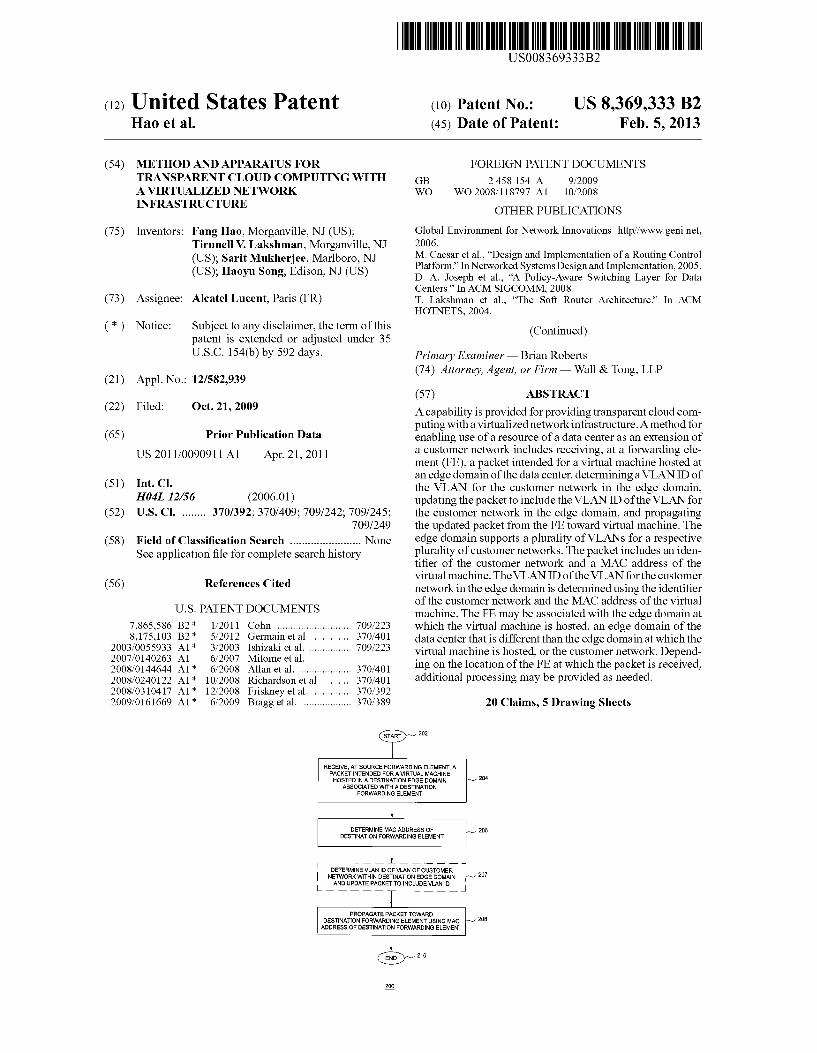
FIG. 1 depicts a high-level block diagram of a communi cation system architecture;
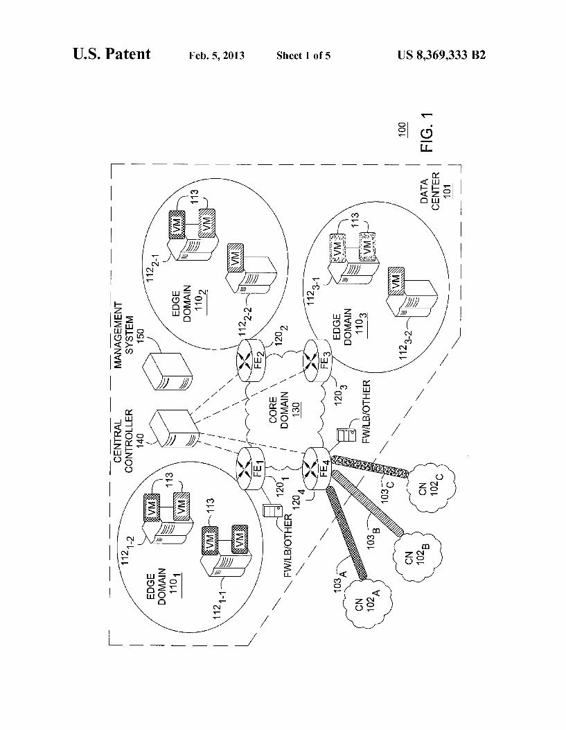
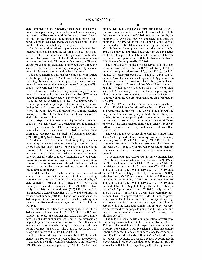
FIG. 2 depicts one embodiment of a method for processing a packet at a source forwarding element, where the packet is intended for a virtual machine hosted in a destination edge domain having a destination forwarding element associated therewith:
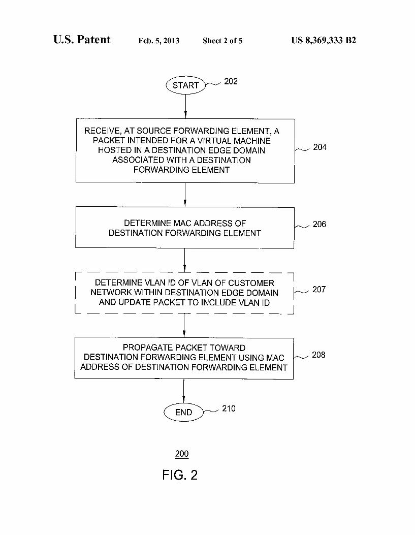
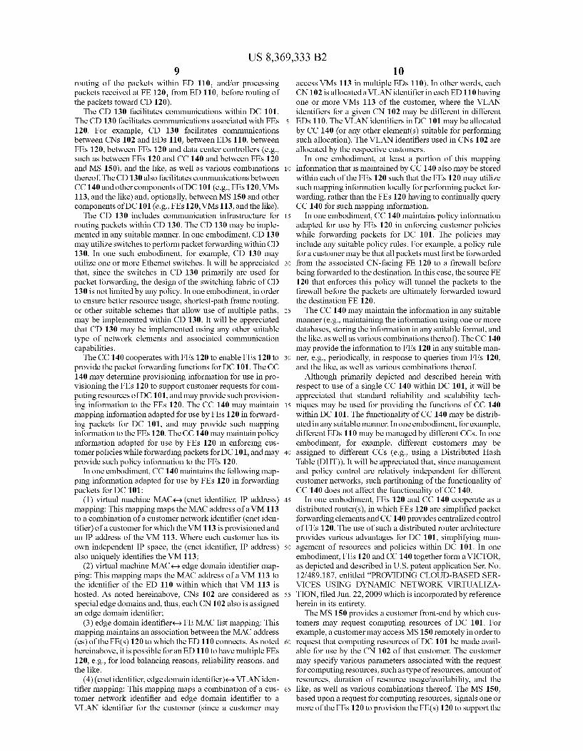
FIG.3 depicts one embodiment of a method for processing a packet at a forwarding element associated with an edge domain hosting a virtual machine for which the packet is intended, where an assumption is made that the forwarding element always determines the VLAN ID of the VLAN of the CN within the edge domain;
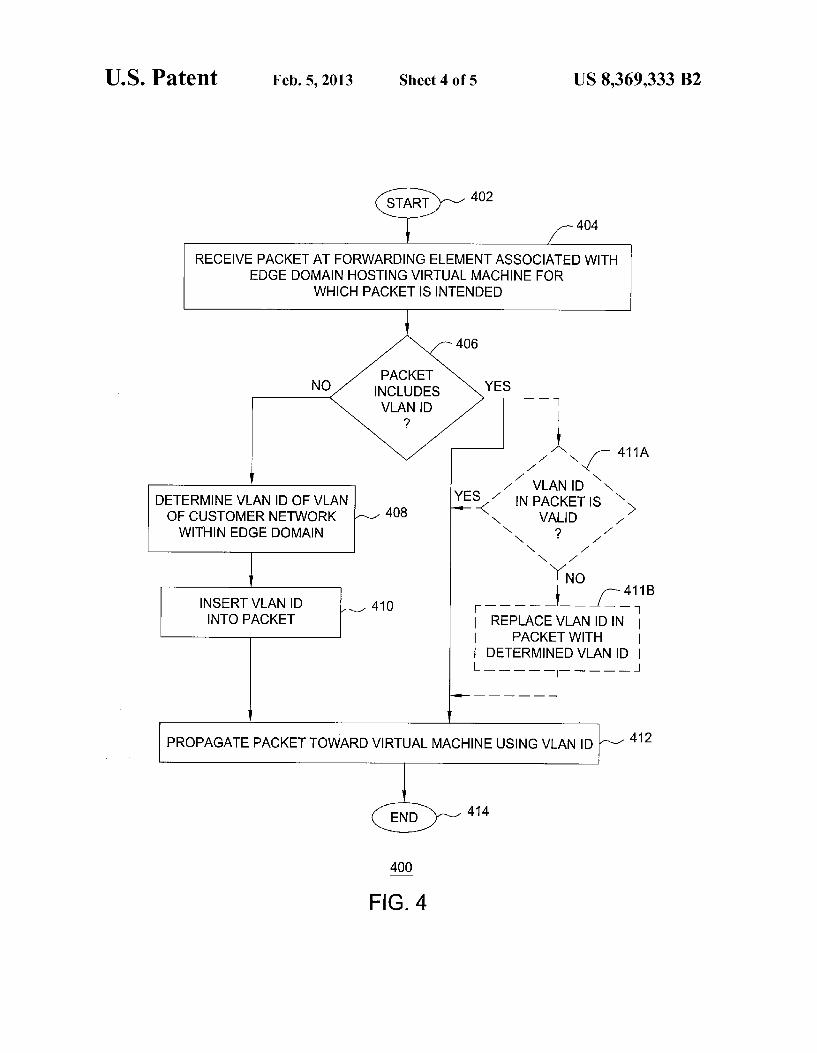
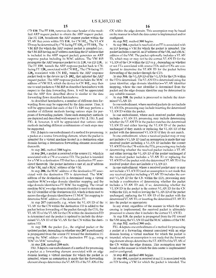
FIG. 4 depicts one embodiment of a method for processing a packet at a forwarding element associated with an edge domain hosting a virtual machine for which the packet is intended, where an assumption is not made that the forward ing element always determines the VLAN ID of the VLAN of the CN within the edge domain; and
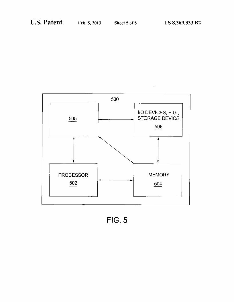
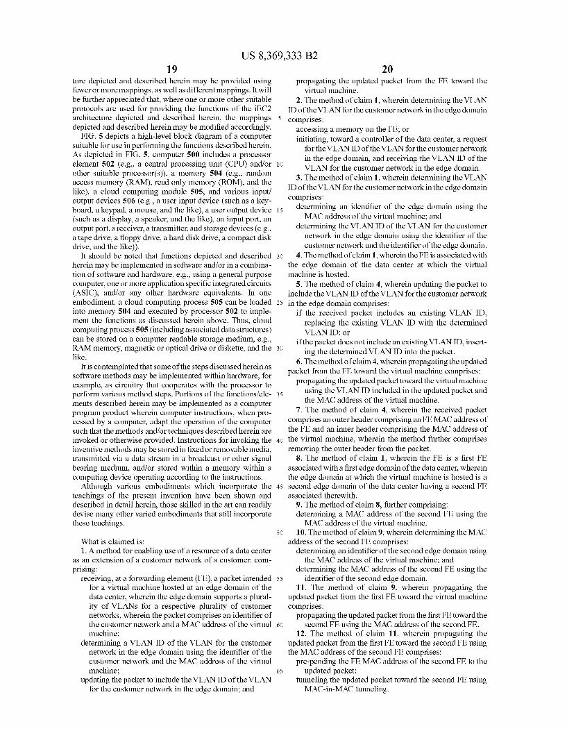
FIG. 5 depicts a high-level block diagram of a general purpose computer Suitable for use in performing the functions described herein. To facilitate understanding, identical reference numerals
have been used, where possible, to designate identical ele ments that are common to the figures.
DETAILED DESCRIPTION OF THE INVENTION
An integrated Elastic Cloud Computing (iEC2) architec ture is depicted and described herein. The iEC2 architecture enables cloud computing resources to be a transparent exten sion to existing customer infrastructure, thereby enabling customer applications to utilize both customer computing resources and cloud computing resources in a seamless and flexible manner without any modification to existing cus tomer infrastructure. The iBC2 architecture enables cloud computing resources to be a transparent extension to existing customer infrastructure by using network virtualization to instantiate virtual extensions of customer networks within the cloud. The iEC2 architecture enables seamless integration of cloud computing resources with existing customer infrastruc ture without requiring any modification of the existing cus tomer infrastructure. The iBC2 architecture enables such extended customer networks to grow and shrink with demand, thereby obviating the need for customers to deploy network infrastructure which may only be needed tempo rarily. The iEC2 architecture enables cloud computing resources to be a transparent extension to existing customer infrastructure in a highly scalable manner, Such that cloud computing resources may be utilized by a very large number customers (e.g., any types of customers ranging from indi
US 8,369,333 B2 3
vidual customers having home networks to large enterprise customers having enterprise networks, rather than existing cloud computing architectures which can only accommodate a small number of customers). The iEC2 architecture enables dynamic customization of the data center for different cus tomers (e.g., dynamic customization of data forwarding, policy control, and like features). The iBC2 architecture enables network virtualization to be
provided. The network virtualization is provided using two types of entities: Forwarding Elements (FEs) and a Central Controller (CC). In general, the FEs perform packet handling functions (e.g., address mapping, policy checking and enforcement, packet forwarding, and the like), while the CC maintains and provides control information adapted for use by the FES in performing the packet handling functions (e.g., configuration information, address mapping, policies, and the like). The FEs may be implemented as Ethernet switches having enhanced APIs that enable them to be controlled remotely by the CC. The iEC2 architecture, unlike in typical network virtualization Solutions, does not require deploy ment of specialized routers or Switches across the entire data center network; rather, the FEs are deployed only at certain chosen points of the data center network in order to provide the virtualization functions, while conventional, off-the-shelf Ethernet switches can be used in most parts of the data center network. TheiEC2 architecture utilizes a hierarchical network struc
ture within the data center network, in which multiple edge domains communicate via a central core domain. The edge domains each include physical hosts (for providing cloud computing resources within the edge domain) connected via one or more switches. The edge domains each provide a number of functions, such as resolving packet addresses (e.g., for resolving the edge domain/layer two address to which a packet should be forwarded), isolating packets of different customers within the edge domain, determining forwarding of packets based on intended destination (e.g., forwarding locally within the edge domain, or toward the core domain for forwarding toward another edge domain), policy checking and enforcement, and the like. The edge domains each are connected to the core domain via one or more FEs (i.e., FEs are deployed as gateways between the edge domains and the core domain, while the CC is associated with the core domain for purposes of communicating with the FES for providing configuration and control functions for the FEs). The cus tomer networks may be treated as special instances of edge domains, in which case each customer network may access the data center network via one or more FEs (where such FEs are referred to as customer-facing FEs (CN-facing FEs) that see the customer network(s) as local LANs). The FEs may have processing devices associated therewith, such as fire walls, load balancers, and the like, for providing policy treat ment of packets traversing the FEs. The core domain may be a flat layer-two network adapted for forwarding packets between edge domains.
In the iEC2 architecture, a customer is provided one or more virtual networks isolated from virtual networks of other customers. The virtual network(s) of a customer may be pro vided in one edge domain or spread across multiple edge domains, with the underlying domain structure being hidden from the customer. In each edge domain, VLANs are utilized locally within the edge domain to isolate different customers that are utilizing resources within the edge domain, and, further, VLAN IDs are reused across edge domains, thereby providing a significant increase in the number of customers which may be supported by the data center network. When a customer network spans multiple edge domains, the customer
10
15
25
30
35
40
45
50
55
60
65
4 network may be assigned different VLAN IDs in each of the multiple edge domains and, packets forwarded across edge domains, such VLAN IDs are remapped by the gateway FEs between the edge domains and the core domain. As described herein, the iEC2 architecture enables seam
less integration of cloud computing resources with customer networks, thereby enabling customers to utilize cloud com puting resources without modification of the customer net works. The seamless integration of cloud computing resources with customer networks may be achieved using an addressing scheme for logically isolating customer networks within the data center network. A description of one exem plary embodiment of Such an addressing scheme follows. The addressing scheme includes a mechanism for differ
entiating between different customers, by which each cus tomer network is assigned a unique customer network iden tifier (referred to herein as a cnet identifier). In the case of a customer having a single VLAN, the cnet identifier also iden tifies the customer. In the case of a customer having multiple VLANs, use of a different cnet identifier for each VLAN ensures that the VLAN structure of the customer may be preserved (which may be desirable or even necessary, Such as where different policy controls are applicable for different VLANs). In this manner, logically, a virtual machine can be identified using a combination of (cnet identifier, IP address). The combination of (cnet identifier, IP address) is mapped to a unique layer two MAC address for the virtual machine. In host virtualization platforms that Support assignment of Vir tual MAC addresses to virtual machines, the unique layer two MAC address for the virtual machine directly identifies the virtual machine, even where other virtual machines may be hosted on the physical server. In host virtualization platforms that do not support assignment of virtual MAC addresses to virtual machines, the layer two MAC address assigned to the virtual machine is the same as the MAC address assigned to the physical server and, thus, an additional identifier is required for purposes of identifying the virtual machine on the physical server. In this case, the additional identifier may be a pseudo MAC address generated for the virtual machine, which is used for virtual machine identification purposes but not for packet forwarding purposes. The addressing scheme includes a mechanism for separat
ing different customers within each edge domain. In addition to using layer two and layer three addresses, VLANs are used to separate different customers within each edge domain. In each edge domain, each customer is mapped to a different VLAN. If a customer has multiple VLANs that use the cloud computing service, each of the internal VLANs of the cus tomer is mapped to a different VLAN in the edge domain. For each edge domain, VLAN configuration is performed at the FE(s) 120 associated with the edge domain, at the Ethernet Switch(es) using for forwarding packets within the edge domain, and at the host hypervisors of the physical servers within the edge domain. The VLAN configurations in the edge domains are transparent to the virtual machines, such that applications that run on the virtual machines are not aware of the VLAN configurations. The addressing scheme includes a mechanism for enabling
edge domains to reuse VLAN IDs. VLAN tagging scope is limited within the edge domains. By enabling edge domains to reuse VLAN IDs, the limit on the number of customers that may be accommodated by the data center network is elimi nated. While this design implicitly imposes a limit on the number of virtual machines that can be supported in each edge domain (e.g., in the worst case, when each virtual machine belongs to a different customer in the edge domain, there can be a maximum of 4000 virtual machines in each
US 8,369,333 B2 5
edge domain; although, in general, edge domains are likely to be able to Support many more virtual machines since many customers are likely to use multiple virtual machines), there is no limit on the number of edge domains that may be Sup ported within the data center and, thus, there is no limit on the number of customers that may be supported. The above-described addressing scheme enables seamless
integration of cloud computing resources with customer net works, while at the same time isolating customer networks, and enables preservation of the IP address spaces of the customers, respectively. This ensures that servers of different customers can be differentiated, even when they utilize the same IP address, without requiring use of physically separate networks for each customer within the data center. The above-described addressing scheme may be modified
while still providing an iEC2 architecture that enables seam less integration of cloud computing resources with customer networks in a manner that prevents the need for any modifi cation of the customer networks. The above-described addressing scheme may be better
understood by way of reference to the exemplary iEC2 archi tecture depicted and described with respect to FIG. 1.
The foregoing description of the iEC2 architecture is merely a general description provided for purposes of intro ducing the iEC2 architecture and, thus, the iEC2 architecture is not limited in view of this description. A more detailed description of the iEC2 architecture, and its various associ ated embodiments, follows.
FIG. 1 depicts a high-level block diagram of a communi cation system architecture. As depicted in FIG. 1, communi cation system architecture 100 is an exemplary iEC2 archi tecture including a data center (DC) 101 providing cloud computing resources for a plurality of customer networks (CNs) 102-102 (collectively, CNs 102). The data center 101 includes cloud computing resources
which may be made available for use by customers (e.g., where customers may lease or purchase cloud computing resources). The cloud computing resources are provided to customers such that they are considered to be extensions of the customer networks of those customers. The cloud com puting resources may include any types of computing resources which may be made available to customers, such as processing capabilities, memory, and the like, as well as Vari ous combinations thereof. The data center 101 includes network infrastructure
adapted for use in facilitating use of cloud computing resources by customers. The DC 101 includes a plurality of edge domains (EDs) 110-110 (collectively, EDs 110), a plurality of forwarding elements (FEs) 120-120 (collec tively, FEs 120), and a core domain (CD) 130. The DC 101 also includes a central controller (CC) 140 and, optionally, a management system (MS) 150. The various elements of DC 101 cooperate to perform various functions for enabling cus tomers to utilize cloud computing resources available from DC 101. The CNS 102 may utilize cloud computing resources of DC
101 without modification of the CNS 102. The CNS 102 may include any types of customer networks, e.g., from home networks of individual customers to enterprise networks of large enterprise customers. In other words, CNS 101 may be any customer networks which may make use of cloud com puting resources of DC 101. The CNS 102 access DC 101 using one or more of the FEs 120 of DC 101. A description of the various components of DC 101 which
enable CNS 102 to access cloud computing resources follows. The EDs 110 enable a significant increase in the number of
CNs 102 which may be supported by DC 101. As described
10
15
25
30
35
40
45
50
55
60
65
6 herein, each ED 110 is capable of supporting a set of VLANs for customers independent of each of the other EDs 110. In this manner, rather than the DC101 being constrained by the number of VLANs that may be supported (and, thus, the number of CNS 102 which may be supported), only each of the individual EDs 110 is constrained by the number of VLANs that may be supported and, thus, the number of CNs 102 which may be supported; however, from the perspective of DC 101, this per-ED limitation on the number of CNS 102 which may be supported is artificial in that any number of EDs 110 may be supported by DC 101. The EDs 110 each include physical servers 112 for use by
customers associated with CNS 102 (illustratively, ED 110 includes two physical servers 112 and 112, ED 110, includes two physical servers 1122- and 112-2, and ED110 includes two physical servers 112 and 112, where the physical servers are referred to collectively as physical serv ers 112). The physical servers 112 each host cloud computing resources which may be utilized by CNS 102. The physical servers 112 may be any servers Suitable for Supporting Such cloud computing resources, which may depend on the type(s) of cloud computing resources being made available for use by CNS 102. The PSs 112 each include one or more virtual machines
(VMs) 113 which may be utilized by CNs 102. For each PS 112 supporting multipleVMs 113, the VMs 113 of the PS 112 may be implemented using any virtualization technique(s) Suitable for logically separating different customer networks on the physical server 112 (and thus, for making different portions of the same physical hardware available for use by different customers in a transparent, secure, and cost-effec tive manner). The VMs 113 are virtual machines configured on PSs 112.
The VMs 113 provide cloud computing resources which may be configured on PSs 112 for use by CNs 102. The cloud computing resources include any resources which may be utilized by CNS 102, such as processor resources, memory resources, and the like, as well as various combinations thereof.
In the exemplary network of FIG. 1, three customers have VMs 113 provisioned within DC101 for use by CNs 102 of the three customers. The first CN 102 has four VMs 113 provisioned within DC 101 (namely, two VMs 113 on PS 112 of ED110, one VM 113 on PS112 of ED110, and one VM 113 on PS 112 of ED 110). The second CN 102 also has four VMs 113 provisioned within DC 101 (namely, one VM 113 on PS 112 of ED 110, one VM 113 on PS 112 of ED110, one VM 113 on PS112 of ED110, and oneVM 113 on PS 112 of ED110). The third CN 102 has two VMs 113 provisioned within DC101 (namely, two VMs 113 on PS 112 of ED 110). From these exemplary cus tomers, it will be appreciated that VMs 113 may be provi sioned within DC 110 in many different configurations (e.g., a customer may utilize one physical server, multiple physical servers within the same edge domain, multiple physical serv ers across the different edge domains, and the like, and, fur ther, a customer may utilize one or more VMS on any given physical server). The EDs 110 each include communication infrastructure
for routing packets within EDs 110. In one embodiment, EDs 110 may utilize switches to perform packet forwarding within EDs 110. For example, EDs 110 each may utilize one or more Ethernet switches. In one embodiment, since the switches in each ED 110 need to handle different VLANs for different customers, the switches in each ED 110 may be configured in a conventional tree-based topology (e.g., rooted at FES 120 associated with EDs 110, respectively). It will be appreciated

US 8,369,333 B2 7
that EDs 110 may be implemented using other types of net work elements and other associated communication capabili ties.
The EDs 110 each have one or more FEs 120 associated therewith. The FEs 120 operate as gateways between EDs 110 and CD 130. It will be appreciated that while one FE 120 per ED 110 is sufficient for the network virtualization functions to be supported within DC101, multiple FEs 120 may be used to interface EDs 110 with CD 130 for purposes of load bal ancing, improved reliability, and the like. The FEs 120 perform packet handling functions (e.g.,
address lookup and mapping, policy checking and enforce ment, packet forwarding and tunneling, and the like) for packets associated with DC 101. The FEs 120 function as gateways between CNs 102 and CD 130 and between EDs 110 and CD 130. The FEs 120 include CN-facing FEs (illus tratively, FE120, which operates as a gateway in DC101 for each of the CNS 102) and ED-facing FEs (illustratively, FEs 120,120, and 120 which operate as gateways between EDs 110, 110, and 110, and CD 130, respectively). The opera tion of the FEs 120 in facilitating communications for CNs 102 and EDs 110 is described in additional detail hereinbe low. The FEs 120 perform address lookup and mapping func
tions. The address lookup and mapping may be performed by an FE 120 using mapping information stored in the local storage of the FE 120 and/or by requesting the required map ping information from CC 140 (e.g., Such as where the required mapping information is not available from the local storage of the FE 120). The mapping information which may be stored locally and/or requested from CC 140 includes any mapping information required for performing the packet han dling functions (e.g., such as the virtual machine MAC ( ) (cnet identifier, IP address) mapping, the virtual machine MAC) edge domain identifier mapping, the edge domain identifier() FE MAC list mapping, and the (cnet identifier, edge domain identifier)é VLAN identifier mapping described herein as being maintained by CC 140). The FEs 120 may perform policy checking and enforce
ment functions. The policies may be general policies enforced by the data center operator and/or customer policies enforced for customers. The policy checking and enforce ment functions may be provided using policy information, which may be stored locally on the FEs 120 and/or requested from CC 140 by the FEs 120 (e.g., where the required policy information is not available locally on the FEs 120). For example, the FEs 120 may process packets to ensure that MAC address, IP address, VLAN IDs, and the like are con sistent for the source and destination of the packet. For example, the FES 120 may apply customer policies (e.g., forwarding packets to firewalls before delivery, utilizing load balancers, and the like). It will be appreciated that FEs 120 may check and enforce any other Suitable data center operator and/or customer policies. The FEs 120 perform packet forwarding functions. The
address lookup and mapping functions may be utilized in conjunction with the packet forwarding functions. For example, FEs 120 may forward packets originating from CNs 102 that are intended for processing by virtual machines within DC 101, forward packets originating from virtual machines within DC 101 that are intended for CNS 102, forward packets originating from virtual machines within DC 101 that are intended for other virtual machines within DC 101, forward control packets exchanged within DC101 (e.g., Such as packets conveying provisioning information mapping information, and the like), and the like.
10
15
25
30
35
40
45
50
55
60
65
8 As may be seen from these exemplary packet flows, FEs
120 may receive packets from EDs 110 and forward the packets via CD 130, receive packets from CD 130 and for ward the packets to EDs 110, receive packets from EDs and forward the packets back within the same EDs 110, and the like. The FEs 120 may perform such packet forwarding using any Suitable packet forwarding capabilities.
In one embodiment, a source FE 120 receiving a packet from a CN 102 or an ED 110 for forwarding to a destination ED 110 via CD 130 tunnels the packet across CD 130 using tunneling. In one Such embodiment, the source FE tunnels the packet using MAC-in-MAC tunneling. In MAC-in-MAC tun neling, the source FE 120 adds an outer MAC header to the Ethernet frame (the header of the Ethernet frame being the internal header), the modified Ethernet frame is routed by the Ethernet switches of CD 130 using the outer MAC header, and the destination FE 120 removes the outer MAC header. It will be appreciated that most Ethernet switches allow larger frame sizes to be used, such that the additional bytes of the outer MAC header will not cause any issues within CD 130 (especially in CD 130, where higher capacity Ethernet switches may be deployed to meet the traffic demands of all of the EDs 110). It will be appreciated that any other suitable type of tunneling may be used.
In one embodiment, an FE 120 receiving a packet for delivery within the ED 110 with which the FE 120 is associ ated (e.g., to a VM 113), forwards the packet within the ED 110 using the MAC address of the VM 113, the IP address of the VM 113, and the VLAN ID of the CN 102 with which the packet is associated. The packet may be routed through the ED 110 via one or more Ethernet switches deployed within the ED 110 for facilitating communications between the FE 120 and the VMS 113 hosted within the ED 110. It will be appreciated that this type of packet forwarding may be per formed for packets received at the FE 120 via CD 130 and for packets originating from within the ED 110 with which the FE 120 is associated (i.e., intra-ED communications). The FEs 120 perform such functions using any information
Suitable for performing Such functions. As indicated herein above, the FEs 120 may access such information in any suit able manner. For example, the FEs 120 may store such infor mation locally (e.g., packet forwarding entries, customer policy rules, and the like) and/or receive such information from one or more remote sources of such information (e.g. via signaling with other FEs 120, via requests to CC 140, and the like). The FEs 120 may support various other capabilities in
addition to the address lookup and mapping functions, the policy checking and enforcement functions, and the packet forwarding functions. The FEs 120 may be implemented in any suitable manner.
In one embodiment, FEs 120 may be implemented as switches. In one such embodiment, for example, FEs 120 may be implemented as high capacity Ethernet Switches Support ing such capabilities. The FEs 120 also may supportenhanced APIs adapted for enabling the FEs 120 to be controlled remotely by CC 140.
In one embodiment, one or more of the FEs 120 may have one or more additional network elements associated there with for use in performing various packet processing func tions (e.g., firewalls, load balancers, and the like). For example, FE 120 has a firewall and load balancer associated therewith for use in processing packets (e.g., processing packets received from CNS 102 before routing of the packets within DC101), and FE120 has a firewall and load balancer associated therewith for use in processing packets (e.g., pro cessing packets received at FE 120 from CD 120 before
US 8,369,333 B2 9
routing of the packets within ED 110 and/or processing packets received at FE 120 from ED 110, before routing of the packets toward CD 120).
The CD 130 facilitates communications within DC 101. The CD 130 facilitates communications associated with FEs 120. For example, CD 130 facilitates communications between CNS 102 and EDs 110, between EDs 110, between FEs 120, between FEs 120 and data center controllers (e.g., Such as between FES 120 and CC 140 and between FES 120 and MS 150), and the like, as well as various combinations thereof. The CD130 also facilitates communications between CC 140 and other components of DC101 (e.g., FEs 120,VMs 113, and the like) and, optionally, between MS 150 and other components of DC101 (e.g., FEs 120, VMs 113, and the like). The CD 130 includes communication infrastructure for
routing packets within CD 130. The CD 130 may be imple mented in any suitable manner. In one embodiment, CD 130 may utilize switches to perform packet forwarding within CD 130. In one such embodiment, for example, CD 130 may utilize one or more Ethernet switches. It will be appreciated that, since the switches in CD 130 primarily are used for packet forwarding, the design of the switching fabric of CD 130 is not limited by any policy. In one embodiment, in order to ensure better resource usage, shortest-path frame routing, or other suitable schemes that allow use of multiple paths, may be implemented within CD 130. It will be appreciated that CD 130 may be implemented using any other suitable type of network elements and associated communication capabilities. The CC 140 cooperates with FEs 120 to enable FEs 120 to
provide the packet forwarding functions for DC101. The CC 140 may determine provisioning information for use in pro visioning the FES 120 to Support customer requests for com puting resources of DC101, and may provide Such provision ing information to the FEs 120. The CC 140 may maintain mapping information adapted for use by FEs 120 in forward ing packets for DC 101, and may provide Such mapping information to the FEs 120. The CC 140 may maintain policy information adapted for use by FEs 120 in enforcing cus tomer policies while forwarding packets for DC101, and may provide such policy information to the FEs 120.
In one embodiment, CC 140 maintains the following map ping information adapted for use by FEs 120 in forwarding packets for DC 101:
(1) virtual machine MAC( ) (cnet identifier, IP address) mapping: This mapping maps the MAC address of a VM113 to a combination of a customer network identifier (cnet iden tifier) of a customer for which the VM113 is provisioned and an IP address of the VM 113. Where each customer has its own independent IP space, the (cnet identifier, IP address) also uniquely identifies the VM 113:
(2) virtual machine MACé) edge domain identifier map ping: This mapping maps the MAC address of a VM 113 to the identifier of the ED 110 within which that VM 113 is hosted. As noted hereinabove, CNS 102 are considered as special edge domains and, thus, each CN 102 also is assigned an edge domain identifier,
(3) edge domain identifier() FEMAC list mapping: This mapping maintains an association between the MAC address (es) of the FE(s) 120 to which the ED 110 connects. As noted hereinabove, it is possible for an ED 110 to have multiple FEs 120, e.g., for load balancing reasons, reliability reasons, and the like.
(4) (cnet identifier, edge domain identifier) ( > VLAN iden tifier mapping: This mapping maps a combination of a cus tomer network identifier and edge domain identifier to a VLAN identifier for the customer (since a customer may
10
15
25
30
35
40
45
50
55
60
65
10 access VMs 113 in multiple EDs 110). In other words, each CN102 is allocated a VLAN identifier in each ED110 having one or more VMs 113 of the customer, where the VLAN identifiers for a given CN 102 may be different in different EDs 110. The VLAN identifiers in DC101 may be allocated by CC 140 (or any other element(s) suitable for performing such allocation). The VLAN identifiers used in CNs 102 are allocated by the respective customers.
In one embodiment, at least a portion of this mapping information that is maintained by CC 140 also may be stored within each of the FEs 120 such that the FEs 120 may utilize Such mapping information locally for performing packet for warding, rather than the FEs 120 having to continually query CC 140 for such mapping information.
In one embodiment, CC 140 maintains policy information adapted for use by FEs 120 in enforcing customer policies while forwarding packets for DC 101. The policies may include any suitable policy rules. For example, a policy rule for a customer may be that all packets must first be forwarded from the associated CN-facing FE 120 to a firewall before being forwarded to the destination. In this case, the source FE 120 that enforces this policy will tunnel the packets to the firewall before the packets are ultimately forwarded toward the destination FE 120. The CC 140 may maintain the information in any suitable
manner (e.g., maintaining the information using one or more databases, storing the information in any suitable format, and the like, as well as various combinations thereof). The CC 140 may provide the information to FEs 120 in any suitable man ner, e.g., periodically, in response to queries from FES 120, and the like, as well as various combinations thereof.
Although primarily depicted and described herein with respect to use of a single CC 140 within DC 101, it will be appreciated that standard reliability and scalability tech niques may be used for providing the functions of CC 140 within DC 101. The functionality of CC 140 may be distrib uted in any suitable manner. In one embodiment, for example, different EDs 110 may be managed by different CCs. In one embodiment, for example, different customers may be assigned to different CCs (e.g., using a Distributed Hash Table (DHT)). It will be appreciated that, since management and policy control are relatively independent for different customer networks, such partitioning of the functionality of CC 140 does not affect the functionality of CC 140.
In one embodiment, FEs 120 and CC 140 cooperate as a distributed router(s), in which FEs 120 are simplified packet forwarding elements and CC 140 provides centralized control of FEs 120. The use of such a distributed router architecture provides various advantages for DC 101, simplifying man agement of resources and policies within DC 101. In one embodiment, FEs 120 and CC 140 together form a VICTOR, as depicted and described in U.S. patent application Ser. No. 12/489,187, entitled “PROVIDING CLOUD-BASED SER VICES USING DYNAMIC NETWORK VIRTUALIZA TION, filed Jun. 22, 2009 which is incorporated by reference herein in its entirety. The MS 150 provides a customer front-end by which cus
tomers may request computing resources of DC 101. For example, a customer may access MS 150 remotely in order to request that computing resources of DC 101 be made avail able for use by the CN 102 of that customer. The customer may specify various parameters associated with the request for computing resources, such as type of resources, amount of resources, duration of resource usage/availability, and the like, as well as various combinations thereof. The MS 150, based upon a request for computing resources, signals one or more of the FEs 120 to provision the FE(s) 120 to support the

US 8,369,333 B2 11
request for computing resources, or signals CC 140 to signal one or more of the FEs 120 to provision the FE(s) 120 to Support the request for computing resources. The provision ing may be performed immediately (e.g., where the request indicates that the computing resources are to be used imme diately), may be scheduled to be performed at a later time (e.g., where the request indicates that the computing resources are to be used at a later time), and the like. The MS 150 also may provide various network management functions within DC 101.
Although primarily depicted and described with respect to a data center having specific types, numbers, and arrange ments of network elements, it will be appreciated that the data center may be implemented using different types, numbers, and/or arrangements of network elements. For example, although primarily depicted and described with respect to use of a single FE 120 to connect an ED 110 to CD 130, it will be appreciated that one or more EDs 110 may be connected to CD 130 via multiple FEs 120 (e.g., for load-balancing, reli ability, and the like). For example, although primarily depicted and described with respect to use of a single CC 140, the functionality of CC 140 may be spread across multiple CCs 140. It will be appreciated that various other modifica tions may be made. As described herein, DC101 enables the CNS 102 to utilize
cloud computing resources of DC 101 without modification of the CNS 102. The CNS 102 may include any types of customer networks,
e.g., from home networks of individual customers to enter prise networks of large enterprise customers. In other words, CNS 101 may be any customer networks which may make use of cloud computing resources of DC 101. The CNS 102 may communicate with DC 101 using any
suitable means of communication (e.g., Virtual Private LAN Services (VPLS), Multi-Protocol Label Switching (MPLS), and the like).
In one embodiment, DC 101 and CN 102 communicate using VPLS. In one such embodiment, in which a CN 102 communicates with DC 101 using VPLS via provider edge (PE) routers of an Internet Service Provider (ISP), a customer edge (CE) device within the CN 102 connects to a first VPLS PE router of the ISP and the CE-acting FE 120 of DC101 that is associated with CN 102 connects to a second VPLS PE router of the ISP. For the CE devices at the ends, the associ ated PE router appears as a local Ethernet switch. In one further embodiment, in order to avoid scalability issues that may arise (e.g., since different ports need to be allocated at both the CE device and PE router interfaces for different customers, so that the total number of customers that can be supported by PEs and CE-acting FEs is limited by the number of ports), QinC encapsulation is used between the CE-acting FE and the PE routers, thereby enabling each port to support up to 4000 customers and, thus, significantly increasing the numbers of customers that can be supported. It will be appre ciated that VPLS may be utilized to support communications between DC101 and CNS 102 in any other suitable manner.
In one embodiment, DC 101 and CN 102 communicate using MPLS. In one such embodiment, in which both DC101 and CN 102 get network connections from the same Internet Service Provider (ISP), MPLS may be used as the underlying transport, and bandwidth may be provisioned for better qual ity of service. In another such embodiment, in which DC101 and CN 102 get network connections from different Internet Service Providers (ISPs), one or more other encapsulation protocols may be utilized for traversing layer three networks (e.g., such as using Generic Routing Encapsulation (GRE) or other encapsulation protocols that are suitable for traversing
10
15
25
30
35
40
45
50
55
60
65
12 layer three networks). It will be appreciated that MPLS may be utilized to support communications between the DC 101 and the CNS 102 in any other suitable manner.
In one embodiment, for individual users or small busi nesses, Layer 2 Tunneling Protocol (L2TP)/Internet Protocol Security (IPSec) may be used between the DC101 and the CN 102 in order to provide basic connectivity and security with out assistance from network service providers.
It will be appreciated that communications between DC 101 and CNS 102 may be implemented using any other suit able types of communications capabilities. As described herein, the iEC2 architecture enables integra
tion of cloud computing resources with customer networks, thereby enabling customers to utilize cloud computing resources without modification of the customer networks. The utilization of cloud computing resources of the data center by customer networks requires exchanging of packets between the data center and the customer networks, as well as exchanging of packets within the data center. A description of different data forwarding paths utilized for providing cloud computing services in the iEC2 architecture follows.
In utilizing the cloud computing service, a device in a CN 102 may send a packet to a VM 113 in DC101. For purposes of clarity in describing the data flow, assume for this example that a packet is sent from a device in CN 102 to the VM 113 that is hosted on PS 112 in ED 110 for CN 102. The packet is forwarded from CN 102 to the CN-facing FE 120 associated with CN102. The packet is received at CN-facing FE 120 associated with CN 102. The packet received at CN-facing FE 120 includes the MAC address and IP address of intended VM 113. The CN-facing FE 120 ensures that the MAC address of intended VM 113 that is included in the packet is consistent with the combination of (cnet id, IP address) using the virtual machine MAC () (cnet identifier, IP address) mapping. The CN-facing FE 120 determines the ED 110 hosting the VM 113 for which the packet is intended (which, in this example, is ED 110 that is hosting intended VM 113 for CN 102) by using the MAC address from the packet to access the virtual machine MAC(-) edge domain identifier mapping. The CN-facing FE 120 determines the MAC address of one of the FES 120 of the identified ED 110 hosting the VM 113 for which the packet is intended (which, in this example, is FE 120 serving ED 110) by using the determined edge domain identifier to access the edge domain identifiere FE MAC list mapping. The CN-facing FE 120 modifies the received packet to include the determined MAC address of the one of the FEs 120 of the ED 110 hosting the VM 113 for which the packet is intended (which, in this example, is the MAC address of FE 120 serving ED 110). For example, CN-facing FE 120 may append the determined MAC address of FE 110 as an outer header of the received packet to form a modified packet. The CN-facing FE 120, optionally, also may access policy information for the cus tomer and apply the policy information as appropriate (e.g., forwarding the packet to FE 110 via a firewall associated with FE 110 or applying any other applicable policy rules) prior to forwarding the modified packet and/or as part of forwarding the modified packet. The CN-facing FE 120 forwards the modified packet toward FE 110 via CD 130. The CD 130 propagates the modified packet based on the MAC address of FE 110 which is used as the outer header of the modified packet (i.e., the modified packet is tunneled from FE 110 to FE 110, via CD 130 using MAC-in-MAC tunnel ing). The FE 110 receives the modified packet via CD 130. The FE 110 removes the outer header of the modified packet to obtain the packet. The FE 110 propagates the packet toward the VM 113 for which the packet is intended via ED

US 8,369,333 B2 13
110. The FE 110 and ED 110 propagate the packet using (a) the VLAN ID of the CN 102 within ED 110 and (b) the MAC address of the VM 113 for which the packet is intended. The VM 113 for which the packet is intended receives the packet. The VM 113 processes the received packet for CN 102. In this data forwarding flow, propagation of the packet within ED 110, which is hosting the VM 113 for which the packet is intended, is performed using the VLAN ID of CN 102 within ED 110. As such, the VLAN ID of CN 102 within ED 110 must be determined within DC 101 and the packet must be modified to include the determined VLAN ID of CN 102 within ED 110. The VLAN ID may be deter mined and inserted into the packet by the source FE (in this example, FE120) or by the destination FE (in this example, FE 120) using the (cnet identifier, edge domain identifier) () VLAN identifier mapping, because both the source and destination FEs know the cnet identifier of CN 102 and the edge domain identifier of ED 110 which is hosting the VM 113 for which the packet is intended. With respect to deter mining the VLAN ID, the following configurations may be used: (a) if the DC 101 is configured such that the source FE is always responsible for determining and inserting the VLAN ID on behalf of the destination FE, the destination FE may always assume that a packet received via CD 130 includes the VLAN ID required for delivery of the packet within the associated ED (i.e., the destination FE does not have to determine whether or not the received packet includes the proper VLAN ID); or (b) if the DC 101 is not configured such that the source FE is always responsible for determining and inserting the VLAN ID on behalf of the destination FE. the destination FE, upon receiving a packet via CD 130, will determine whether or not the received packet includes a VLAN ID and (b1) if the received packet does not include a VLAN ID, the destination FE will determine the VLAN ID using the (cnet identifier, edge domain identifier)ex VLAN identifier mapping and will insert the determined VLAN ID into the packet, or (b2) if the received includes a VLAN ID, the destination FE will either assume that the VLAN ID is valid, or will determine the VLAN ID using the (cnet identi fier, edge domain identifier) ( > VLAN identifier mapping and compare it to the VLAN ID included within the received packet such that the VLAN ID in the packet may be replaced with the determined VLAN ID if the compared VLAN IDs do not match.
In utilizing the cloud computing service, a VM 113 in DC 101 may send a packet to a device in a CN 102. The data forwarding flow in this case is very similar to the data for warding flow of the above-described case in which a CN 102 sends a packet to a VM113 in DC101, because each CN 102 is essentially a special edge domain.
In utilizing the cloud computing service, a first VM 113 in DC 101 may send a packet to a second VM in DC 101. If the first VM113 and second VM113 are in different EDs 110, the data forwarding flow in this case is very similar to the data forwarding flow of the above-described case in which a CN 102 sends a packet to a VM 113 in DC101. If the first VM 113 and second VM 113 are in the same ED 110 but associated with different VLANs, the packet must be delivered via one of the FES 120 associated with the ED 110 Such that the one of the FEs 120 associated with the ED 110 may translate the VLAN ID and, optionally, perform policy checking and enforcement. If the first VM 113 and Second VM 113 are in the same ED 110 and associated with the same VLAN, the packet from a source VM 113 can be delivered directly to a destination VM 113 (i.e., without a requirement that the
5
10
15
25
30
35
40
45
50
55
60
65
14 packet traverse the FE 120), because address lookup and mapping and policy checking and enforcement are not required.
In one or more of the above-described data forwarding flows, an ARP process may be employed for learning MAC addresses. This enables the source devices of the packets in the data forwarding flows described above to know the MAC address of the destination device for which the packets are intended.
In such embodiments, the ARP process may be applied before the first packet is received at a source FE 120 from an end point (e.g., from a device in CN 102 or from a VM 113) or in response to the first packet being received at a source FE 120 from an end point (e.g., from a device in CN 102 or from a VM 113).
In such embodiments, the ARP flow is similar to the data forwarding flows described above. For purposes of clarity in describing the ARP flow, the ARP flow is described within the context of the data forwarding flow in which a device in a CN 102 wants to send a packet to a VM 113 in DC101 (although it will be appreciated that the ARP process is applicable to other types of data forwarding flows). For further purposes of clarity in describing the ARP flow, assume for this example that a device in CN 102 wants to sent a packet to the VM113 hosted on PS 112 in ED 110 for CN 102, but does not know the MAC address of the VM 113 hosted on PS 112 in ED 110 for CN 102. In this case, in order to learn the MAC address, the device in CN 102 initiates an ARP request packet. The ARP request packet is forwarded from CN 102 to the CN-facing FE 120 associated with CN 102. The ARP request packet is received at CN-facing FE 120 associated with CN102. The ARP request packet received at CN-facing FE 120 includes the cnetid of CN 102 and the IP address of the intended VM 113, but not the MAC address of the intended VM 113. The CN-facing FE 120 determines the MAC address of intended VM 113 using the virtual machine MAC(-) (cnet identifier, IP address) mapping. At this point, it will be appreciated that, while the CN-facing FE 120 now has sufficient information to response to the ARP request (and, thus, could do so), Switches typically do not response to ARP messages (rather, they simply forward ARP messages for processing by end devices). Thus, CN-facing FE 120 determines the ED 110 hosting the VM 113 for which the packet is intended (which, in this example, is ED 110 that is hosting intended VM 113 for CN 102) by using the deter mined MAC address of the VM 113 to access the virtual machine MACé) edge domain identifier mapping. The CN facing FE120 determines the MAC address of one of the FEs 120 of the identified ED 110 hosting the VM 113 for which the packet is intended (which, in this example, is FE 120 serving ED110) by using the determined edge domain iden tifier to access the edge domain identifiere FE MAC list mapping. The CN-facing FE 120 modifies the received ARP request packet to include the determined MAC address of the one of the FEs 120 of the ED 110 hosting the VM 113 for which the packet is intended (which, in this example, is the MAC address of FE 120 serving ED 110). For example, CN-facing FE120 may append the determined MAC address of FE 110 as an outer header of the ARP request packet to form a modified ARP request packet. The CN-facing FE 120 forwards the modified ARP request packet toward FE 110 via CD 130. The CD 130 propagates the modified ARP request packet based on the MAC address ofFE 110 which is used as the outer header of the modified ARP request packet (i.e., the modified ARP request packet is tunneled from FE 110 to FE 110 via CD 130 using MAC-in-MAC tunneling). The FE 110 receives the modified ARP request packet via
US 8,369,333 B2 15
CD 130. The FE 110 removes the outer header of the modi fied ARP request packet to obtain the ARP request packet. The FE 110 broadcasts the ARP request packet within the VLAN that exists within ED 110 for CN 102. The VLAN ID may be determined by CN-facing FE 120 or FE 110. The VM 113 for which the ARP request packet is intended (i.e., the VM113 having an IP address matching the IP address that is included in the ARP request packet) generates an ARP response packet including its MAC address. The VM 113 propagates the ARP response packet to FE 110 via ED110. The FE 110 tunnels the ARP response packet back to CN facing FE 120 associated with CN 102. The CN-facing FE 120 associated with CN 102 tunnels the ARP response packet back to the device in CN 102 that initiated the ARP request packet. The ARP response packet includes the MAC address of VM 113, which the device in CN 102 may then use to send packets to VM113 as described hereinabove with respect to the data forwarding flows. It will be appreciated that the ARP flow described above is similar to the data forwarding flows described hereinabove. As described hereinabove, a number of different data for
warding flows may be supported by the data center. Thus, it will be appreciated that each of the FEs 120 may perform a number of different methods having various steps for pur poses of forwarding packets. Three Such exemplary methods are depicted and described with respect to FIG. 2, FIG.3, and FIG. 4; however, it will be appreciated that various other methods including different combinations of Such steps may be supported.
FIG. 2 depicts one embodiment of a method for processing a packet at a source forwarding element, where the packet is intended for a virtual machine hosted in a destination edge domain having a destination forwarding element associated therewith.
At step 202, method 200 begins. At step 204, a packet is received at the source FE, which is
associated with a CN or a source ED. The packet is intended for a VM in a destination ED that has a destination FE asso ciated therewith. The packet includes a cnet id, an IP address of the VM, and a MAC address of the VM. At step 206, the MAC address of the destination FE asso
ciated with the destination ED is determined. The MAC address of the destination FE is determined using a virtual machine MAC () edge domain identifier mapping and the edge domain identifiere FE MAC list mapping. The virtual machine MAC () edge domain identifier is used to determine the ED identifier of the destination ED, which is then used to access the edge domain identifiere). FEMAC list mapping to determine MAC address of the destination FE. At step 207 (optionally, e.g., where the VLAN ID of the
VLAN for the CN within the destination ED is added to the packet before forwarding of the packet through the CD), the VLAN ID of the VLAN for the CN within the destination ED is determined and the packet is updated to include the deter mined VLAN ID of the VLAN for the CN within the desti nation ED. At step 208, the packet (i.e., the original packet or the
updated packet, depending on whether step 207 is performed) is propagated from the source FE toward the destination FE using the MAC address of the destination FE (e.g., using MAC-in-MAC tunneling).
At step 210, method 200 ends. FIG.3 depicts one embodiment of a method for processing
a packet at a forwarding element associated with an edge domain hosting a virtual machine for which the packet is intended, where an assumption is made that the forwarding element always determines the VLAN ID of the VLAN of the
10
15
25
30
35
40
45
50
55
60
65
16 CN within the edge domain. This assumption may be based on the manner in which the data center is implemented and/or configured. At step 302, method 300 begins. At step 304, a packet is received at an FE is associated with
an ED hosting a VM for which the packet is intended. The packet includes acnetid, an IP address of the VM, and a MAC address of the VM. The packet optionally includes a VLAN ID, which may or may not be the correct VLAN ID for the VLAN of the CN within the ED (e.g., depending on whether or not FEs associated with source EDs and/or CNs are con figured to determine the VLAN ID for the packet before forwarding of the packet through the CD). At step 306, the VLAN ID of the VLAN for the CN within
the ED is determined. The VLAN ID is determined using the (cnet identifier, edge domain identifier)(-) VLAN identifier mapping, where the cnet identifier is determined from the packet and the edge domain identifier may be determined in any Suitable manner. At step 308, the packet is processed to include the deter
mined VLAN ID. In one embodiment, where received packets do not include
VLAN IDs, processing may include inserting the determined VLAN ID within the packet.
In one embodiment, where each received packet already includes a VLAN ID, processing may include determining whether the VLAN ID in the packet matches the determined VLAN ID and either leaving the VLAN ID of the packet unchanged if they match or replacing the VLAN ID of the packet with the determined VLAN ID if they do not match.
In one embodiment, where a received packet may or may not include a VLAN ID (and an assumption is made that any received packet including a VLAN ID includes the correct VLAN ID for the CN within the ED), processing may include determining whether the received packet includes a VLAN and either leaving the VLAN ID of the packet unchanged if the received packet includes a VLAN ID or replacing the VLAN ID of the packet with the determined VLAN ID if the received packet does not include a VLAN ID.
In one embodiment, where a received packet may or may not include a VLAN ID (and an assumption is not made that any received packet including a VLAN ID includes the cor rect VLAN ID for the CN within the ED), processing may include a combination of determining whether the packet includes a VLAN ID and, if so, determining whether the VLAN ID in the packet is the correct VLAN ID for the CN within the ED, as well as leaving the VLAN ID of the packet unchanged, replacing the VLAN ID of the packet with the determined VLAN ID, or inserting the determined VLAN ID into the packet as appropriate.
In any event, regardless of the manner in which the pro cessing is implemented, the received packet is ultimately processed to ensure that it includes the correct VLAN ID. At step 310, the packet is propagated from the FE toward
the VM using the VLAN ID and the MAC address of the VM. At step 312, method 300 ends. FIG. 4 depicts one embodiment of a method for processing
a packet at a forwarding element associated with an edge domain hosting a virtual machine for which the packet is intended, where an assumption is not made that the forward ing element always determines the VLAN ID of the VLAN of the CN within the edge domain. This assumption may be based on the manner in which the data center is implemented and/or configured. At step 402, method 400 begins. At step 404, a packet is received at an FE is associated with
an ED hosting a VM for which the packet is intended. The

US 8,369,333 B2 17
packet includes acnetid, an IP address of the VM, and a MAC address of the VM. The packet optionally includes a VLAN ID, which may or may not be the correct VLAN ID for the VLAN of the CN within the ED (e.g., depending on whether or not FEs associated with source EDs and/or CNs are con figured to determine the VLAN ID for the packet before forwarding of the packet through the CD).
At step 406, a determination is made as to whether or not the packet includes a VLAN ID.
If the packet does not include a VLAN ID, method 400 proceeds to steps 408 and 410, in succession. At step 408, the VLAN ID of the VLAN for the CN within the ED is deter mined. The VLAN ID is determined using the (cnet identifier, edge domain identifier) ( > VLAN identifier mapping, where the cnet identifier is determined from the packet and the edge domain identifier may be determined in any suitable manner. At step 410, the packet is updated to include the determined VLAN ID. From step 410, method 400 proceeds to step 412.
If the packet includes a VLAN ID, method 400 optionally proceeds to one or more of steps 411 (where there is no assumption that the VLAN ID in the packet is valid) or, otherwise, proceeds directly to step 412 (where there is an assumption that the VLAN ID in the packet is valid). At optional step 411A, a determination is made as to whether or not the VLAN ID in the packet is valid (e.g., by determining the VLAN ID of the VLAN for the CN within the ED using information from the packet and one or more mappings and comparing the determined VLAN ID to the VLAN ID included in the packet). If the VLAN ID in the packet is valid, method 400 proceeds from step 411A to step 412. If the VLAN ID in the packet is not valid, method 400 proceeds to step 411B, at which point the VLAN ID in the packet is replaced by the determined VLAN ID, and method 400 pro ceeds to step 412.
At step 412, the packet is propagated from the FE toward the VM using the VLAN ID and the MAC address of the VM.
At step 414, method 400 ends. Although primarily depicted and described as being per
formed serially, at least a portion of one or more of above described methods 200, 300, and 400 may be performed contemporaneously, or in a different order than depicted and described with respect to FIGS. 2, 3, and 4, respectively. As described herein, customers may utilize data center
resources to transparently provide extensions to customer networks. The iEC2 architecture enables customers to obtain layer 2 and/or layer 3 network extensions.
In layer 2 network extension, the virtual servers in the data center are logically in the same LAN as the customer servers in the customer network. This is beneficial, because certain applications may require that the servers running the appli cation be part of the same LAN. This also is beneficial, because it is easier to migrate virtual servers within the same LAN. In general, layer 2 extension is typically more flexible than layer 3 extension.
In layer 3 network extension, the virtual servers in the data center are not in the same Subnet as the customer network. The customer may have one or more subnets within the data center. In general, layer 3 networks may be needed for having more servers, for policy reasons, and the like.
In one embodiment, in order to Support layer 3 extensions for customers, FEs 120 and CC 140 may support additional router functions. The additional router functions may include, for each customer for which layer 3 extensions are supported, enabling at least one virtual router to be allocated for the
5
10
15
25
30
35
40
45
50
55
60
customer, where the virtual router(s) peers with the outer(s) of 65 the customer network. In this arrangement, data is forwarded by FEs 120, and the routing protocol is run at CC 140.
18 With respect to providing different types of extensions, it
will be appreciated that migration within the data center is independent of network layers because virtual servers are made location independent (i.e., they can run at any physical hosts), whereas migration between customer networks and the data center across different Subnets is more challenging. In one embodiment, migration between customer networks and the data centeracross different subnets may be performed by deploying, at the edge of the customer network, an FE that is adapted to register the location of the virtual server and to tunnel packets to/from FEs within the data center. As depicted and described hereinabove, the iEC2 architec
ture provides a number of advantages over existing cloud based computing architectures. The iEC2 architecture provides effective isolation between
different customer networks. This includes Supporting private IP address spaces of customers (which may be potentially overlapping across customers), isolating traffic of customers, and providing like isolation functions. This also may include performing resource allocation Such that no customer can impact the resource usage of any other customer in an uncon trolled manner. The iEC2 architecture provides transparency for custom
ers, such that the underlying infrastructure of the data center is transparent to the customers. In this manner, each customer has a logical view of its own network, including cloud com puting resources in the data center, independent of the actual implementation of the data center. This provides numerous advantages, including simplification of administration for the customers, improved security for the customers, and the like. The iEC2 architecture provides location independence for
customers. The virtual servers and networks for the custom ers may be physically located anywhere within the data cen ter. This provides numerous advantages, including improve ment of resource utilization, simplification of provisioning, and the like. The iEC2 architecture provides easy customer policy con
trol, enabling customers to configure policy settings on the fly, enforce policy settings in the network, and the like. This is advantageous, especially since each customer may have its own policy and security requirements (e.g., home customers may need only basic firewall protection whereas enterprise customers may need multiple security Zones having different access controls). The iEC2 architecture is highly scalable. The number of
customer that may be supported is restricted only by resources available in the data center, not by design artifacts such as VLAN scalability issues. The iBC2 architecture is low cost. The iBC2 architecture
enables cloud service providers to rely on off-the-shelf devices for most devices such that new investment for the cloud service providers may be reduced. The iEC2 architec ture enables cloud service providers to share their resources amongst different customers, because allocating physically separate networks and resources for different customers is cost prohibitive.
Although primarily depicted and described herein with respect to use of Ethernet (and, thus, use of MAC addresses) for providing the functions of the iEC2 architecture depicted and described herein, it will be appreciated that the functions of the iEC2 architecture depicted and described herein may be provided using any other Suitable protocols and associated addresses.
Although primarily depicted and described herein with respect to use of specific mappings for providing the func tions of the iEC2 architecture depicted and described herein, it will be appreciated that the functions of the iEC2 architec
US 8,369,333 B2 19
ture depicted and described herein may be provided using fewer or more mappings, as well as different mappings. It will be further appreciated that, where one or more other suitable protocols are used for providing the functions of the iEC2 architecture depicted and described herein, the mappings depicted and described herein may be modified accordingly.
FIG. 5 depicts a high-level block diagram of a computer suitable for use in performing the functions described herein. As depicted in FIG. 5, computer 500 includes a processor element 502 (e.g., a central processing unit (CPU) and/or other suitable processor(s)), a memory 504 (e.g., random access memory (RAM), read only memory (ROM), and the like), a cloud computing module 505, and various input/ output devices 506 (e.g., a user input device (such as a key board, a keypad, a mouse, and the like), a user output device (such as a display, a speaker, and the like), an input port, an output port, a receiver, a transmitter, and storage devices (e.g., a tape drive, a floppy drive, a hard disk drive, a compact disk drive, and the like)).
It should be noted that functions depicted and described herein may be implemented in Software and/or in a combina tion of Software and hardware, e.g., using a general purpose computer, one or more application specific integrated circuits (ASIC), and/or any other hardware equivalents. In one embodiment, a cloud computing process 505 can be loaded into memory 504 and executed by processor 502 to imple ment the functions as discussed herein above. Thus, cloud computing process 505 (including associated data structures) can be stored on a computer readable storage medium, e.g., RAM memory, magnetic or optical drive or diskette, and the like.
It is contemplated that some of the steps discussed hereinas software methods may be implemented within hardware, for example, as circuitry that cooperates with the processor to perform various method steps. Portions of the functions/ele ments described herein may be implemented as a computer program product wherein computer instructions, when pro cessed by a computer, adapt the operation of the computer such that the methods and/or techniques described herein are invoked or otherwise provided. Instructions for invoking the inventive methods may be stored in fixed or removable media, transmitted via a data stream in a broadcast or other signal bearing medium, and/or stored within a memory within a computing device operating according to the instructions.
Although various embodiments which incorporate the teachings of the present invention have been shown and described in detail herein, those skilled in the art can readily devise many other varied embodiments that still incorporate these teachings.
What is claimed is: 1. A method for enabling use of a resource of a data center
as an extension of a customer network of a customer, com prising:
receiving, at a forwarding element (FE), a packet intended for a virtual machine hosted at an edge domain of the data center, wherein the edge domain Supports a plural ity of VLANs for a respective plurality of customer networks, wherein the packet comprises an identifier of the customer network and a MAC address of the virtual machine;
determining a VLAN ID of the VLAN for the customer network in the edge domain using the identifier of the customer network and the MAC address of the virtual machine;
updating the packet to include the VLAN ID of the VLAN for the customer network in the edge domain; and
10
15
25
30
35
40
45
50
55
60
65
20 propagating the updated packet from the FE toward the
virtual machine. 2. The method of claim 1, wherein determining the VLAN
ID of the VLAN for the customer network in the edge domain comprises:
accessing a memory on the FE; or initiating, toward a controller of the data center, a request
for the VLAN ID of the VLAN for the customer network in the edge domain, and receiving the VLAN ID of the VLAN for the customer network in the edge domain.
3. The method of claim 1, wherein determining the VLAN ID of the VLAN for the customer network in the edge domain comprises:
determining an identifier of the edge domain using the MAC address of the virtual machine; and
determining the VLAN ID of the VLAN for the customer network in the edge domain using the identifier of the customer network and the identifier of the edge domain.
4. The method of claim 1, wherein the FE is associated with the edge domain of the data center at which the virtual machine is hosted.
5. The method of claim 4, wherein updating the packet to include the VLAN ID of the VLAN for the customer network in the edge domain comprises:
if the received packet includes an existing VLAN ID, replacing the existing VLAN ID with the determined VLAN ID; or
if the packet does not include an existing VLAN ID, insert ing the determined VLAN ID into the packet.
6. The method of claim 4, wherein propagating the updated packet from the FE toward the virtual machine comprises:
propagating the updated packet toward the virtual machine using the VLAN ID included in the updated packet and the MAC address of the virtual machine.
7. The method of claim 4, wherein the received packet comprises an outer header comprising an FEMAC address of the FE and an inner header comprising the MAC address of the virtual machine, wherein the method further comprises removing the outer header from the packet.
8. The method of claim 1, wherein the FE is a first FE associated with a first edge domain of the data center, wherein the edge domain at which the virtual machine is hosted is a second edge domain of the data center having a second FE associated therewith.
9. The method of claim 8, further comprising: determining a MAC address of the second FE using the MAC address of the virtual machine.
10. The method of claim 9, wherein determining the MAC address of the second FE comprises:
determining an identifier of the second edge domain using the MAC address of the virtual machine; and
determining the MAC address of the second FE using the identifier of the second edge domain.
11. The method of claim 9, wherein propagating the updated packet from the first FE toward the virtual machine comprises:
propagating the updated packet from the first FEtoward the second FE using the MAC address of the second FE.
12. The method of claim 11, wherein propagating the updated packet from the first FE toward the second FE using the MAC address of the second FE comprises:
pre-pending the FE MAC address of the second FE to the updated packet;
tunneling the updated packet toward the second FE using MAC-in-MAC tunneling.
US 8,369,333 B2 21
13. The method of claim 1, wherein the FE is a first FE associated with the customer network, wherein the edge domain at which the virtual machine is hosted has a second FE associated therewith.
14. The method of claim 13, further comprising: determining a MAC address of the second FE using the MAC address of the virtual machine.
15. The method of claim 13, whereindetermining the MAC address of the second FE comprises:
determining an identifier of the edge domain using the MAC address of the virtual machine; and
determining the MAC address of the second FE using the identifier of the edge domain.
16. The method of claim 13, wherein propagating the updated packet from the first FE toward the virtual machine comprises:
propagating the updated packet from the first FEtoward the second FE using the MAC address of the second FE.
17. The method of claim 16, wherein propagating the updated packet from the first FE toward the second FE using the MAC address of the second FE comprises:
pre-pending the FE MAC address of the second FE to the updated packet;
tunneling the updated packet toward the second FE using MAC-in-MAC tunneling.
18. The method of claim 1, further comprising: determining a policy associated with the customer network
using the identifier of the customer network; and applying the determined policy to the packet prior to or
while propagating the packet toward the virtual machine.
19. An apparatus for enabling use of a resource of a data center as an extension of a customer network of a customer, comprising:
a processor and a memory communicatively connected to the processor, the processor configured to: receive, at a forwarding element (FE), a packet intended
for a virtual machine hosted at an edge domain of the data center, wherein the edge domain Supports a plu
5
10
15
25
30
35
22 rality of VLANs for a respective plurality of customer networks, wherein the packet comprises an identifier of the customer network and a MAC address of the virtual machine;
determine a VLAN ID of the VLAN for the customer network in the edge domain using the identifier of the customer network and the MAC address of the virtual machine;
update the packet to include the VLAN ID of the VLAN for the customer network in the edge domain; and
propagate the updated packet from the FE toward the vir tual machine.
20. A method for enabling use of a resource of a data center as an extension of a customer network of a customer, com prising:
receiving, at a forwarding element (FE) associated with an edge domain of the data center, a packet intended for a virtual machine hosted in the edge domain of the data center, wherein the packet comprises an identifier of the customer network, an IP address of the virtual machine, and a MAC address of the virtual machine;
when the received packet includes a VLAN ID of the cus tomer network within the edge domain, propagating the received packet toward the virtual machine using the VLAN ID of the customer network within the edge domain and the MAC address of the virtual machine;
when the received packet does not include a VLAN ID of the customer network within the edge domain: determining a VLAN ID of the customer network within
the edge domain using the MAC address of the virtual machine;
updating the packet to include the VLAN ID of the customer network within the edge domain; and
propagating the updated packet toward the virtual machine using the VLAN ID of the customer network within the edge domain and the MAC address of the virtual machine.