Embed Size (px)
Citation preview

Session 3515
Visualizing Structural Behavior:Using Physical Models in Structural Engineering Education
Karl F. Meyer, Stephen J. Ressler, Thomas A. LenoxUnited States Military Academy
This paper describes the use of physical models for in-class demonstrations in an undergraduate structuralsteel design course. The eight models described herein were developed by the authors and have all been usedsuccessfully in the classroom for at least four consecutive semesters. We have found that these modelssignificantly enhance students’ understanding of structural behavior and improve their ability to visualizethree-dimensional structural systems.
Introduction
In general, design of steel structural systems is accomplished by first envisioning every possible failuremode -- or limit state -- for the system and its constituent members; then proportioning the members such thatnone of these limit states can occur under the required loading conditions. Modern steel design codes specifydesign strength equations corresponding to each limit state, thus providing designers with a consistent, rationalbasis for assessing the adequacy of a given member. The typical introductory steel design course is principallyconcerned with teaching these strength equations and their application, for all pertinent limit states associatedwith various types of structural components--tension members, compression members, beams, beam-columns,and connections.
Herein lies the great challenge for the instructor in an undergraduate steel course: to fully understand aparticular design strength equation, the student must also understand (and be able to visualize) theassociated structural behavior. The student who cannot visualize lateral-torsional buckling, for example,generally cannot correctly apply the lateral-torsional buckling strength equation in the design of a beam. Thestudent who does not understand the nature of block shear cannot possibly design a bolted tension connection.The instructor’s challenge, then, is to convey the nature of the structural behavior associated with each limitstate. The task is not an easy one: many steel failure modes are quite complex, and the differences betweenthem are often subtle.
We firmly believe that the best means of communicating steel member behavior in the classroom isthrough the use of physical models. Thus we have designed and constructed a variety of physical modelsand have used them extensively in our introductory structural steel design course, taught at the United StatesMilitary Academy. In developing these models, we focused on three principal objectives:
- Each model must clearly illustrate the particular aspects of structural behavior most relevant to the designof the corresponding type of member;
<k:d; 1996 ASEE Annual Conference Proceedings‘..,c?ll?><.
Page 1.524.1
-The models must be simple and relatively inexpensive to construct; and
-The models must be durable enough to withstand rough handling by instructors and students throughrepeated use.
The eight most interesting of these models are described in the following paragraphs.
Lateral-Torsional Buckling Demonstrator
Having learned about two-dimensional beam behavior in their introductory mechanics of materials andstructural analysis courses, many students find it difficult to understand that steel beams ofien fail in the thirddimension, by lateral buckling out of the plane of bending. Students have difficulty visualizing this behaviorand, in particular, are unable to see the relationship between the unbraced length of the beam and the designflexural strength. The shorter the unbraced length, the more likely the member is to reach its fully plasticstrength; the longer, the more likely the member is to undergo lateral-torsional buckling.
The lateral-torsional buckling (LTB) demonstrator (Figure 1) illustrates this behavior clearly. Thedevice consists of a simply supported beam, mounted horizontally in a wooden support frame. The beamconsists of a thin piece of Plexiglas that is stiff about its strong axis, yet very flexible about its weak axis,similar to a wide-flange beam. Mounted on the frame are three fold-down supports that simulate intermediatebracing, much like joists framing into a floor beam. These supports restrict only the lateral movement of thebeam; vertical deflection remains unrestrained at these points. One or more of these supports can be loweredinto position, to create unbraced lengths of one quarter, one half, or one full span length. When a load isplaced on the beam in each of these configurations, the effect of unbraced length on flexural strength is readilyapparent. More important, the LTB demonstrator gives students an excellent appreciation for what lateral-torsional buckling looks like, for a variety of different buckling modes.
Flexural Buckling Demonstrator
When developing the Euler buckling equation, simple diagrams are adequate to represent the deflectedshape of an ideal column with pinned ends. However, when one modifies the Euler equation to account forother than pinned ends, using the effective length factor K, the task of illustrating compression memberbehavior becomes more difficult. The challenge is greater still when the unbraced lengths corresponding tothe two axes of bending are unequal.
The flexural buckling demonstrator (Figure 2) was developed to illustrate the effects of different endconditions and intermediate bracing on compression member behavior. The device consists of a compressionmember mounted vertically in a wooden support frame. Again the member consists of a three foot longPlexiglas strip. Both of the wooden blocks which support the member ends can be configured as pinned orfixed supports. In addition, a hinged intermediate support maybe moved into place to reduce the unbracedlength of the member about its weak axis by half. During class, the instructor can easily demonstrate howchanging member end conditions and unbraced length affects compressive strength.
?$igtij 1996 ASEE Annual Conference Proceedings‘Oqllly’.:
Page 1.524.2
Built-up Member Demonstrator
Another concept that some students struggle with is the effect of intermediate connectors on the flexuralbuckling strength of built-up double-angle compression members. We explain this effect using the built-upmember demonstrator (Figure 3). The device consists of two strips of Plexiglas about three feet in length,each representing a single element of a double-angle member. The strips are connected together with smallbolts, washers, and wingnuts, representing the intermediate connectors on a built-up member. The washerskeep the two strips separated from each other. During class, the instructor begins with the strips fastened onlyat the ends. As he applies a slight compressive load to the member, the two strips buckle individually. Byadding intermediate connectors during the demonstration, the instructor can clearly show how both themembers can be made to buckle simultaneously, as a single unit, thereby increasing the compressive strengthsignificantly.
Column Base Plate Demonstrator
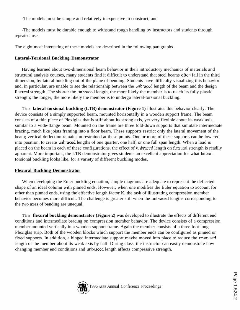
The column base plate demonstrator (Figure 4) is used to show how a steel column base plate is used toprevent bearing failure of the concrete footing on which it rests. This is by far the simplest of our learningaids, yet it is perhaps the most effective. The model consists of a small block of Styrofoam, representing thefooting, a square of plywood (not shown) representing the base plate, and a short length of a steel wide-flangeshape, representing the column. To demonstrate why a base plate is needed, the instructor places the“column” directly on the “footing”. He stands on the column to produce an axial load, and the students canimmediately see and hear the Styrofoam footing failing in bearing. When the plywood base plate is insertedbetween the column and footing, and the load test is repeated, the footing emerges virtually unscathed.Students can clearly see how the base plate distributes the column axial force over a broad area to preventfailure of the concrete below. In addition, flexural deformations of the base plate itself clearly illustrate thebasis for selecting base plate thickness--flexural failure of the plate.
Miniature Steel Tension Connections
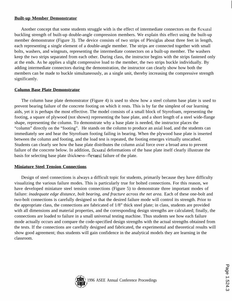
Design of steel connections is always a difficult topic for students, primarily because they have difficultyvisualizing the various failure modes. This is particularly true for bolted connections. For this reason, wehave developed miniature steel tension connections (Figure 5) to demonstrate three important modes offailure: inadequate edge distance, bolt bearing, and fracture across the net area. Each of these one-bolt andtwo-bolt connections is carefully designed so that the desired failure mode will control its strength. Prior tothe appropriate class, the connections are fabricated of 1/8” thick steel plate; in class, students are providedwith all dimensions and material properties, and the corresponding design strengths are calculated; finally, theconnections are loaded to failure in a small universal testing machine. Thus students see how each failuremode actually occurs and compare the code-specified design strengths with the actual strengths obtained fromthe tests. If the connections are carefully designed and fabricated, the experimental and theoretical results willshow good agreement; thus students will gain confidence in the analytical models they are learning in theclassroom.
{fiii~ 1996 ASEE Annual Conference Proceedings‘J31HJ
Page 1.524.3

Static Connection Models
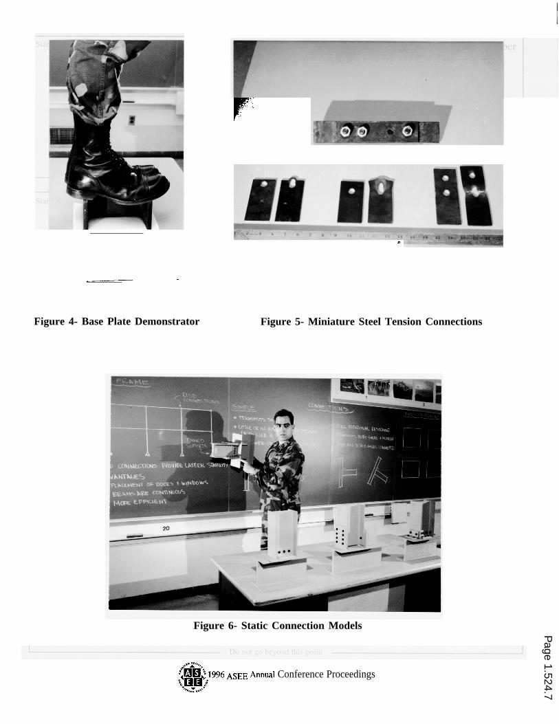
For all but the simplest connection geometries, students often have great difficulty in reading two-dimensional drawings and visualizing the corresponding three-dimensional object. To address this problem,we use a large number of static connection models (Figures 6 and 7). These wooden models are accurate 3-dimensional representations of typical tension, simple beam, semi-rigid, and rigid connections. Each oneincludes all appropriate components--connecting angles and plates, bolts, and welds. During classes onconnection design, the instructor refers to these models to identify specific components; he can draw on themodels with chalk to explain failure planes and limit states; and he can compare the physical models with thecorresponding drawings, so students can practice associating two-dimensional and three-dimensionalrepresentations of the same object.
Several of the models are specifically designed to illustrate the “block shear” failure mode. These models(Figure 7) have built-in block shear failures, which can be “activated” by pulling the two halves of theconnection apart. These models clearly illustrate the tension and shear failure planes associated with this limitstate.
Rigid and Braced Frame Demonstrators
We use the rigid and braced frame demonstrators (Figure 8) to show how various types of lateral loadcarrying systems work. Both models are constructed with thin strips of aluminum sheet, representing beamsand columns. In the rigid frame demonstrator, these members are interconnected with relatively rigid angleconnectors and rivets. In the braced frame demonstrator, the beams are connected to the columns with smallhinges. Hinges connect the columns to the wooden bases in both models. Thanks to these hinges, the bracedframe model is laterally unstable, until bracing members are inserted into the structure. Several differentbracing systems can be installed. These include X, K, and knee bracing (creating an eccentrically bracedframe, or EBF), as well as pieces of Styrofoam that simulate concrete shear walls. The different bracing typesare easily interchangeable. Thus, in class, the instructor can use the models to demonstrate how each systemachieves its lateral stability, and to illustrate the relative effectiveness of each system in controlling lateraldrift.
K’NEX Building Set
Often we have felt the need to model a particular structure, or perhaps just a portion of a structure, toillustrate a teaching point or to explain an upcoming design project. We have found an ideal tool for thispurpose--the K’NEX Building Set (Figure 9). K’NEX is a commercially developed children’s toy, consistingof various standardized structural components. The color-coded pieces are easy to assemble and disassemble.The large variety of members and connectors ensures that nearly any structural system can be modeled. Wehave used this product to model plate girders, trusses, rigid and braced frames, and entire building systems.We have used it effectively in our structural steel course and, more recently, in our Capstone civil engineeringdesign course as well. In the Capstone course, each student design team receives a K’NEX set, to be used indeveloping a structural scheme, as part of a comprehensive design of a building system. The K’NEX modelhelps the students to visualize the three-dimensional structural system and to understand how it behaves underload. The model becomes an integral part of each team’s project submission and is a focal point of the oralpresentation each group gives upon completion of their concept design. Student reaction to the use of K’NEX
Page 1.524.4

has been very positive, and we have noted a marked improvement in their ability to develop structural systemsas a direct result of its use.
Conclusion
The authors firmly believe that physical models provide the best means of communicating the nature ofstructural behavior to students. We have experienced great success with the structural models described abovein our undergraduate structural steel design course. Many of these models would work very effectively inother courses as well. We have found that these models significantly enhance students’ understanding ofstructural behavior and improve their ability to visualize three-dimensional structural systems.
Any engineering educators who are interested in constructing these models for their own use may obtaindimensioned drawings from the authors at no cost. Write to us at:
Civil Engineering DivisionDepartment of Civil and Mechanical EngineeringUnited States Military AcademyWest Point, New York 10996
Or e-mail: [email protected]. edu
MAJOR KARL F. MEYERMAJ Karl F. Meyer is an Assistant Professor in the Dept. of Civil and Mechanical Engineering at the U. S.Military Academy, West Point. He graduated from US MA in 1984 and earned M.S. degrees from theUniversity of Southern California in 1989 and Georgia Tech in 1993. He has taught courses in strength ofmaterials, design of steel structures and design of structural systems.
LIEUTENANT COLONEL STEPHEN J. RESSLERLTC Stephen J. Ressler is an Associate Professor in the Dept. of Civil and Mechanical Engineering at the U. S.Military Academy, West Point, and is a registered professional engineer in Virginia. He graduated from US MAin 1979 and received a Ph.D. degree from Lehigh University in 1991. He has taught courses in statics anddynamics, mechanics of materials, steel design, reinforced concrete design, and design of structural systems.
COLONEL THOMAS A. LENOXCOL Thomas A. Lenox is a Professor of Civil Engineering at the United States Military Academy, and theDirector of USMA’s Civil Engineering Program. He holds leadership positions in the CE Division, the MechDivision, and the Middle-Atlantic Section of ASEE.
@xi!i’~ 1996 ASEE AnnualConference Proceedings‘O,+,pyll’$’
Page 1.524.5

Figure 1- Lateral-torsional Buckling Demonstrator
“., . .
Figure 2- Flexural Buckling Demonstrator
/), !.. , , .,
Figure 3- Built-up Member Demonstrator
:,. . .,, ,, .,,_
$iii-’) 1996 ASEE Annual Conference Proceedings‘.,.,~ylj.
Page 1.524.6
.— -
Figure 4- Base Plate Demonstrator
—
r“~.
$.
.,’” .
n
Figure 5- Miniature Steel Tension Connections
Figure 6- Static Connection Models
?@xaj 1996 ASEE Annual Conference Proceedings‘.,,RYR’;
Page 1.524.7

Figure 9- K’NEX Building Set
Figure 7- Block Shear Failure Demonstrators
Figure 8- Rigid and Braced Frame Demonstrators
?@iii:}. 1996 ASEE Annual Conference Proceedings‘.JC3’J32:
Page 1.524.8