Embed Size (px)
Citation preview

Indian Journal of Marine Sciences
Vol. 38(3), September 2009, pp. 324-331
Vision based distance measurement system using single laser pointer
design for underwater vehicle
Muljowidodo K1, Mochammad A Rasyid
2, SaptoAdi N
2 & Agus Budiyono
3*
1 Mechanical Engineering Program, Mechanical Engineering and Aeronautics Faculty, InstitutTeknologi Bandung (ITB)
Ganesha 10, Bandung, West Java, Indonesia
[E-mail: [email protected]] 2 Center for Unmanned System Studies (CentrUMS), InstitutTeknologi Bandung (ITB), Ganesha 10, Bandung, West Java, Indonesia
[E-mail: [email protected], [email protected]] 3 Corresponding Author, Department of Aerospace Information, Smart Robot Center, Konkuk University
1 Hwayang-Dong, Seoul 143-701, Korea
[E-mail: [email protected]]
Received 26 July 2009, revised 11 September 2009
As part of a continuous research and development of underwater robotics technology at ITB, a vision- based distance
measurement system for an Unmanned Underwater vehicle (UUV) has been designed. The proposed system can be used to
predict horizontal distance between underwater vehicle and wall in front of vehicle. At the same time, it can be used to
predict vertical distance between vehicle and the surface below it as well. A camera and a single laser pointer are used to
obtain data needed by our algorithm. The vision-based navigation consists of two main processes which are the detection of
a laser spot using image processing and the calculation of the distance based on laser spot position on the image.
[Keywords: Vision Based, Image Processing, Laser Spot]
Introduction Design and development of several UUV
prototypes have been conducted elsewhere1. Vision
based navigation has been investigated and an
approach by using single laser pointer is presented in
this paper. UUV is usually equipped with camera as
the “eye” of the operator. On other hand, camera
supported by computer vision can also give some
important information. In this paper it is proposed the
design of system and algorithm to be used for
calculating horizontal and vertical distance between
an object and camera. Beside the camera, a laser
pointer is used for the setup. It is assumed that a
standard computer is used for image processing and
data calculation. Typical underwater vehicle platform
installed with camera and laser pointer is depicted
in Fig. 1.
There are two major works in designing this
distance measurement system. First is obtaining a real
time image processing algorithm needed for laser
spot/mark detection. Second is finding a scaling factor
or formula that convert the object position (pixels) on
the image into real world position (meters). The paper
comprises the relevant aspects of image processing
requirement, image processing algorithm, camera
mounting, laser pointer mounting, detail calculation
of distance measurement and the experimental results.
_____________
*Author for Correspondence
Fig. 1—Underwater vehicle platform with camera and laser
pointer

MULJOWIDODO et al.: VISION BASED DISTANCE MEASUREMENT SYSTEM
325
Materials and Methods
Image processing requirement
In our system, we need appearance of object on the
image captured by video camera. Based on the
detected object one can measure the relative distance
between object and the camera. To be implemented in
real time, one must be able to process the images with
a frequency of at least 25 frames per second.
There are many well-known algorithms such as
MSER2, SIFT
3, etc. to be used for object detection
and recognition. The main problem with those
algorithms is the processing time. It takes few
hundreds milliseconds up to few seconds for complex
image per frame. Thus, it is difficult to be used as part
of a real time control system. Considering this
limitation, it is necessary to develop as simple image
processing algorithm as possible.
It is assumed that a laser pointer can produce a
salient spot. This saliency can simplify the detection
and recognition of image processing task. It reduces
processing time substantially. In our proposed
technique, we just use a laser pointer instead of two
lasers as proposed in elsewhere4.
Image processing algorithm
A red laser pointer is used for experiment. The light
spot of the laser is object to detect. It is a relatively
simple object. There was no need of a complex
feature extraction algorithm. It required a red
segmentation or separation as main task filtering in
our image processing algorithm. Then, by applying a
simple object center finding we can obtain the
position of the detected object. The algorithms for
color segmentation or separation have been
introduced in many papers5. The present study also
presents implementations for a traffic sign
recognition. In the past, our red segmentation was
based on HSV (Hue, Saturation, Value) color space.
This is a standard method for color segmentation.
Color can be represented by only hue components.
Moreover, hue is invariant to the variations in light.
This is the important feature of hue. We used only hue
colors, while others use hue-saturation color. Red lies
in certain range value in hue color space. By applying
a simple thresholding, red can be separated from other
colors based on that range value. One should define
the range so that our intended red object can be
thresholded as distinct as possible. The main
drawback of this algorithm is that we have to set up a
good range value of red. It is not easy to have a good
value since a certain range of values could work in
some situation but fail in others.
An algorithm presented in Flegh5
et al offers a
solution to overcome this dynamic behavior. It is
called dynamic threshold algorithm. It takes into
consideration the variation of global color of the
image. The range value of red used for thresholding is
influenced by this global value. In their experiment, a
red segmentation based on this algorithm yields a
good result. Whereas, in our system we cannot
achieve a real time processing using that algorithm.
It is proposed a simple red segmentation with no
value setting. Our algorithm converts RGB color
space into a single component color space which
represents the degree of red. The redder the color of a
pixel in RGB color space, the higher degree of red it
will have. Let Ri, Gi, Bi be the Red, Green, Blue
values of a pixel. Let DRi be the degree of red of a
pixel. For all pixel then:
Ri = Ri - (Gi+Bi)
Gi = Ri - Gi
Bi = Ri - Bi
If (Ri<0) Ri = 0
If (Gi<0) Gi = 0
If (Bi<0) Gi = 0
DRi = Ri + Gi + Bi
These formula try to measure the degree of red
compared to other colors. The red degree of each
RGB component is calculated as presented by the
formula. Finally, the degrees are totalized to obtain
degree of red of a pixel. Fig. 2 is an example of the
algorithm implementation applied on a laser spot.
Beside the algorithm we use some filtering, such as
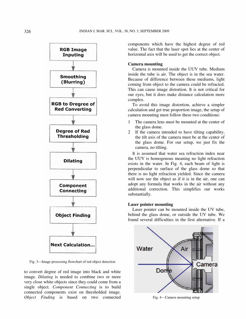
smoothing and dilating for image conditioning. Fig. 3
is a diagram of part of the program :Input RGB
image. Smoothing is needed to eliminate the effect of
camera noise. RGB to Degree of Rred Converting has
been presented above. Degree of Red Thresholding is
Fig. 2—RGB to degree of red conversion
INDIAN J. MAR. SCI., VOL. 38, NO. 3, SEPTEMBER 2009
326
to convert degree of red image into black and white
image. Dilating is needed to combine two or more
very close white objects since they could come from a
single object. Component Connecting is to build
connected components exist on thresholded image.
Object Finding is based on two connected
components which have the highest degree of red
value. The fact that the laser spot lies at the center of
horizontal axis will be used to get the correct object.
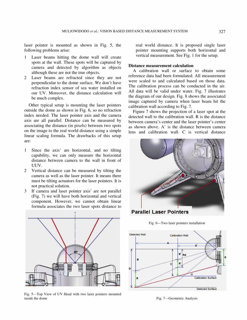
Camera mounting Camera is mounted inside the UUV tube. Medium
inside the tube is air. The object is in the sea water.
Because of difference between these mediums, light
coming from object to the camera could be refracted.
This can cause image distortion. It is not critical for
our eyes, but it does make distance calculation more
complex.
To avoid this image distortion, achieve a simpler
calculation and get true proportion image, the setup of
camera mounting must follow these two conditions:
1 The camera lens must be mounted at the center of
the glass dome.
2 If the camera intended to have tilting capability,
the tilt axis of the camera must be at the center of
the glass dome. For our setup, we just fix the
camera, no tilting.
It is assumed that water sea refraction index near
the UUV is homogenous meaning no light refraction
exists in the water. In Fig. 4, each beam of light is
perpendicular to surface of the glass dome so that
there is no light refraction yielded. Since the camera
will now see the object as if it is in the air, one can
adopt any formula that works in the air without any
additional correction. This simplifies our works
substantially.
Laser pointer mounting
Laser pointer can be mounted inside the UV tube,
behind the glass dome, or outside the UV tube. We
found several difficulties in the first alternative. If a
Fig. 3—Image processing flowchart of red object detection
Fig. 4—Camera mounting setup
MULJOWIDODO et al.: VISION BASED DISTANCE MEASUREMENT SYSTEM
327
laser pointer is mounted as shown in Fig. 5, the
following problems arise:
1 Laser beams hitting the dome wall will create
spots at the wall. These spots will be captured by
camera and detected by algorithm as objects
although these are not the true objects.
2 Laser beams are refracted since they are not
perpendicular to the dome surface. We don’t have
refraction index sensor of sea water installed on
our UV. Moreover, the distance calculation will
be much complex.
Other typical setup is mounting the laser pointers
outside the dome as shown in Fig. 6, so no refraction
index needed. The laser pointer axis and the camera
axis are all parallel. Distance can be measured by
associating the distance (in pixels) between two spots
on the image to the real world distance using a simple
linear scaling formula. The drawbacks of this setup
are:
1 Since the axis’ are horizontal, and no tilting
capability, we can only measure the horizontal
distance between camera to the wall in front of
UUV.
2 Vertical distance can be measured by tilting the
camera as well as the laser pointer. It means there
must be tilting actuators for the laser pointers. It is
not practical solution.
3 If camera and laser pointer axis’ are not parallel
(Fig. 7) we will have both horizontal and vertical
component. However, we cannot obtain linear
formula associates the two laser spots distance to
real world distance. It is proposed single laser
pointer mounting supports both horizontal and
vertical measurement. See Fig. 1 for the setup.
Distance measurement calculation A calibration wall or surface to obtain some
reference data had been formulated. All measurement
were scaled to and calculated based on those data.
The calibration process can be conducted in the air.
All data will be valid under water. Fig. 7 illustrates
the diagram of our design. Fig. 8 shows the associated
image captured by camera when laser beam hit the
calibration wall according to Fig. 7.
Figure 7 shows the projection of a laser spot at the
detected wall to the calibration wall. R is the distance
between camera’s center and the laser pointer’s center
as shown above. A’ is the distance between camera
lens and calibration wall. C is vertical distance
Fig. 5—Top View of UV Head with two laser pointers mounted
inside the dome
Fig. 6—Two laser pointers installation
Fig. 7—Geometric Analysis
INDIAN J. MAR. SCI., VOL. 38, NO. 3, SEPTEMBER 2009
328
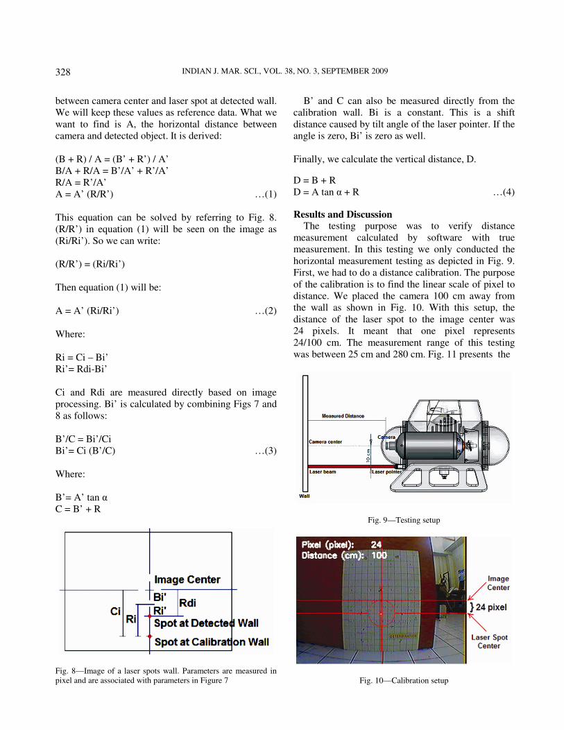
between camera center and laser spot at detected wall.
We will keep these values as reference data. What we
want to find is A, the horizontal distance between
camera and detected object. It is derived:
(B + R) / A = (B’ + R’) / A’
B/A + R/A = B’/A’ + R’/A’
R/A = R’/A’
A = A’ (R/R’) …(1)
This equation can be solved by referring to Fig. 8.
(R/R’) in equation (1) will be seen on the image as
(Ri/Ri’). So we can write:
(R/R’) = (Ri/Ri’)
Then equation (1) will be:
A = A’ (Ri/Ri’) …(2)
Where:
Ri = Ci – Bi’
Ri’= Rdi-Bi’
Ci and Rdi are measured directly based on image
processing. Bi’ is calculated by combining Figs 7 and
8 as follows:
B’/C = Bi’/Ci
Bi’= Ci (B’/C) …(3)
Where:
B’= A’ tan α
C = B’ + R
B’ and C can also be measured directly from the
calibration wall. Bi is a constant. This is a shift
distance caused by tilt angle of the laser pointer. If the
angle is zero, Bi’ is zero as well.
Finally, we calculate the vertical distance, D.
D = B + R
D = A tan α + R …(4)
Results and Discussion The testing purpose was to verify distance
measurement calculated by software with true
measurement. In this testing we only conducted the
horizontal measurement testing as depicted in Fig. 9.
First, we had to do a distance calibration. The purpose
of the calibration is to find the linear scale of pixel to
distance. We placed the camera 100 cm away from
the wall as shown in Fig. 10. With this setup, the
distance of the laser spot to the image center was
24 pixels. It meant that one pixel represents
24/100 cm. The measurement range of this testing
was between 25 cm and 280 cm. Fig. 11 presents the
Fig. 8—Image of a laser spots wall. Parameters are measured in
pixel and are associated with parameters in Figure 7
Fig. 9—Testing setup
Fig. 10—Calibration setup

MULJOWIDODO et al.: VISION BASED DISTANCE MEASUREMENT SYSTEM
329
Fig. 11—True distance versus measured distance
INDIAN J. MAR. SCI., VOL. 38, NO. 3, SEPTEMBER 2009
330
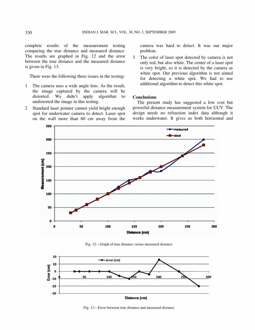
complete results of the measurement testing
comparing the true distance and measured distance.
The results are graphed in Fig. 12 and the error
between the true distance and the measured distance
is given in Fig. 13.
There were the following three issues in the testing:
1 The camera uses a wide angle lens. As the result,
the image captured by the camera will be
distorted. We didn’t apply algorithm to
undistorted the image in this testing.
2 Standard laser pointer cannot yield bright enough
spot for underwater camera to detect. Laser spot
on the wall more than 60 cm away from the
camera was hard to detect. It was our major
problem.
3 The color of laser spot detected by camera is not
only red, but also white. The center of a laser spot
is very bright, so it is detected by the camera as
white spot. Our previous algorithm is not aimed
for detecting a white spot. We had to use
additional algorithm to detect this white spot.
Conclusions
The present study has suggested a low cost but
powerful distance measurement system for UUV. The
design needs no refraction index data although it
works underwater. It gives us both horizontal and
Fig. 12—Graph of true distance versus measured distance
Fig. 13—Error between true distance and measured distance

MULJOWIDODO et al.: VISION BASED DISTANCE MEASUREMENT SYSTEM
331
vertical measurement. Our future project would be
embedding this applications into a low cost single
board computer instead PC or DSP. It should be
possible since the calculation and its image processing
are not so complex, we expect that the proposed
system would work with comparable performance.
Based on issues and the testing results, it is concluded
that the effective range for the measurement system is
30 cm to 150 cm with maximum error of 10 cm. To
increase the measurement range it is planned to use a
stronger/brighter laser beam and enlarge the distance
between the camera center and the laser pointer
center. The image distortion did not affect the
accuracy of the measurement
Acknowledgement
The corresponding author was supported by the
MKE (Ministry of Knowledge Economy), Korea
under the ITRC (Information Technology Research
Centre) support program supervised by the IITA
(Institute for Information Technology Advancement)
(IITA-2009-C1090-0902-0026).
References 1 Muljowidodo K, Sapto Adi N, Said D Jennie & Agus
Budiyono. 2006. Design, Development and Testing
Underwater Vehicle: ITB Experience. In Proceeding of
International Conference On Underwater System
Technology: Theory and Applications, Penang Malaysia.
2 Lowe D G, Distinctive image features from scale-invariant
key points. In International Journal of Computer Vision,
2004.
3 Matas J, Chum O, Urban M & Pajdla T, Robust wide
baseline stereo from maximally stable external regions. In
Proc. of British Machine Vision Conference, pages 384-396,
2002.
4 Rzhanov Y, Mamaenko A & Yoklavich M, UVSD: Software
for Detection of Color Underwater Features.
5 Fleyeh H, Traffic and Road Sign Recognition. In thesis,
Napier University, 2008.