Embed Size (px)
Citation preview

1
Ultrasonic Distance Measurement Method withCrosstalk Rejection at High Measurement Rate
Seungin Shin, Min-Hyun Kim, and Seibum B. Choi, Member, IEEE,
Abstract—This paper introduces a computationally intensivemethod for measuring distance at high measurement rates usingchaotic pulse position modulation (CPPM) signals and single-bitsignal processing in a single ultrasound sensor system. To preventcrosstalk from other ultrasonic sensor systems a chaotic system isused, and an ultrasonic pulses are transmitted as a pulse sequencegenerated by CPPM. After receiving the ultrasound signal, thesingle-bit signal was generated by a fast Fourier transformthreshold, which also functions as an environmental noise filter.Single-bit signal processing has been adopted to reduce thecomputational load when cross-correlating the transmitted andreceived signals for time of flight (TOF) calculations. Single bitsignal processing has more than 100 times memory saving effectin this study. Additionally, as the signal to noise ratio (SNR)increases, extension of the maximum measurable distance inultrasonic distance sensor system is expected. The simulationshows the crosstalk rejection performance of the proposedmethod and the experimental results confirm the improvementof the measurement speed by the proposed method.
Index Terms—Chaotic pulse position modulation (CPPM),sonar distance measurement, distance measurement, measure-ment methods, signal to noise ratio (SNR), sonar signal process-ing, signal processing.
I. INTRODUCTION
OVER TIME, vehicles, mobile robots and productionlines have been acquiring various sensors. In particular,
sensors that measure distance to nearby objects are essentialto smart systems. Currently, laser sensors, ultrasonic sensors,stereo cameras, and radio detection and ranging (RADAR)and light detection and ranging (LIDAR) systems are widelyused as distance sensors. Time of flight (TOF) cameras arealso being studied to provide three-dimensional imaging athigh frame rates [1]. Among them, ultrasonic sensors are verycheap and the sensor system is small in size and easy tohandle, but due to the physical limitations of ultrasound, theperformance, accuracy and measurement rate are usually lowerthan with other sensor systems. Accordingly, software researchhas focused on overcoming the physical limitations.
Most studies on ultrasonic distance sensors have focusedon increasing the performance of ultrasonic sensors by addingadditional information to the ultrasonic wave. There are manyways to store information in ultrasound signals: for example,frequency modulation, signal coding by pulse width modu-lation (PWM), pulse position modulation (PPM) and phasemodulation.
The authors are with the Department of Mechanical Engineering, KAIST,291, Daehak-ro, Yuseong-gu, Daejeon, Republic of Korea (e-mail: [email protected], [email protected], [email protected]).
Since the 1980s, many studies have been conducted toprevent collisions. In the field of obstacle avoidance, pioneer-ing studies have been made by Borenstein and Koren [2]–[5]. After that, efforts were made to improve the accuracyof ultrasonic sensors in the field of robotics considering themultiuser problem. Precise ultrasonic pulse detection methodsusing various signal processing methods, other than the simplethreshold method, have been studied. Barker codes, Golaycodes, and Kasami codes were used by several researchersfor ultrasonic local positioning system [6]–[10]. The cross-correlation method was used for pulse detection [11], [12].Jorg and Berg [13]–[16] used a pseudorandom code to solvethe crosstalk problem. However, these methods for accurateultrasonic pulse detection are inadequate for automotive ap-plications because of their high computational load whichrequires a high performance microcontroller.
Several researchers introduced binary frequency shift keying(BFSK) modulation to produce emission signals [17]–[20].The frequency modulation technique requires wide frequencyband piezoelectric transducers which are usually high priced.
Currently, research on signal coding methods aims to solvethe crosstalk problem in the mobile robot multi-ultrasonicsensor system. In vehicle applications, external crosstalk mayoccur when the opposite vehicle is using ultrasonic sensorson a narrow one-lane street, or when there is an ultrasonicsensor on the side of a vehicle in the other lane on an urbanroad. Crosstalk is a big problem in practical applications ofultrasonic sensors. A review journal [21] introduced researchup to 2005 on crosstalk elimination methods. It is essential todistinguish each ultrasonic sensor to reject crosstalk. When aseries of ultrasonic pulse sequences are generated using thechaotic pulse position modulation (CPPM), each ultrasonictransducer can be made unique, so it was possible to distin-guish each ultrasonic sensor: This means crosstalk elimination.
Borenstein and Koren [22], [23] introduced the idea ofcomparison of consecutive readings and comparison withalternating delays called error eliminating rapid ultrasonicfiring (EERUF). Then, as the computer processing capabilityincreased, a cross-correlation method was used to comparethe sequences. Fortuna et al. [24], [25] applied chaotic pulse-position modulation (CPPM) to fire the sonar sensor, andchaotic pulse position-width modulation (CPPWM) was usedby Yao et al. [26] to obtain better results. To enhance real-timeperformance, Meng et al. [27] proposed short optimized pulse-position modulation sequences. Alonge [28] applied RADARtechnology to an ultrasonic sensor system.
Unlike the studies described above, the focus of this re-search was to increase the measurement rate of the ultrasonic

2
sensor system in a multiuser environment. CPPM signalsovercome the crosstalk and multiuser problem, and by usingthe signal coding method the distance to the object canbe measured robustly at a high measurement rate, which isdifferent from the conventional simple time of flight (TOF)method (single pulse echo method). In addition, there areobstacles to overcome for vehicular application. The sensorsystem must be robust to environmental noise and able tomeasure moving targets. Basically, it should be available ina multiuser situation and, above all, be cost competitive. Inaddition, general automotive control applications require aroot mean square (RMS) error of less than 50 mm and ameasurement rate of over 100 Hz.
In a conventional single pulse echo method, the transmittercannot emit additional ultrasonic pulses while the last pulsesare still in flight because each ultrasonic pulse cannot bedistinguished. In this study, the TOF is obtained by compar-ing ultrasonic pulse sequences rather than comparing singleultrasonic pulses. When calculating the TOF, the time delaywas calculated by cross-correlation between the transmittedpulse sequence and the received pulse signal. However, cross-correlation of a long signal typically requires high computingcosts. Therefore, in order to reduce the computational load,single-bit signal processing, introduced by Hirata et al. in [29]and [30], was used in the cross-correlation process to reducethe computational load and improve real-time performance. Byreplacing multi-bit products with single-bit logical productsin cross-correlation, the amount of computation was greatlyreduced. In [29] and [30], single-bit signal processing wasapplied to reduce the computing cost of detecting singleultrasonic pulses. However, in this study, single-bit signalprocessing was applied to the cross-correlation of CPPMsignal sequences.
Section 2 introduces the hardware system used in the ex-periment and explains the physical limitations of the classicalmethod. Section 3 introduces the hardware system used inthe experiment and the chaotic system. Section 4 deals withsignal processing for real-time distance measurement; thefast Fourier transform (FFT) threshold was used for noisecancellation, and subsampling and single-bit signal processingwere used to reduce the computational load. The results of thecrosstalk rejection simulation are shown in Section 5, and theresults of the distance measurement experiment showing themeasurement rate are given in Section 6.
II. MEASUREMENT METHOD
A. TOF method
Ultrasonic distance sensors use a TOF method. In thesimplest way, the controller measures the time from departureto echo arrival. The more advanced methods measure thesignal delay by comparing the transmitted signal with thereceived signal. The signal delay can be measured by cross-correlation, which is discussed later in this paper.
d = C · ttof/2 (1)
where d is the target distance, C is the speed of sound inthe air, and ttof indicates the flight time of the sound pulse
measured through this system. The speed of sound varies withtemperature and humidity. The linear model is:
C = 331.3 + 0.606 · θ + 0.0124 ·H (2)
where θ is the temperature in degrees Celsius, and H isthe relative humidity. Temperature changes can cause largechanges in the speed of sound, so real-time temperaturemeasurement is basic and is necessary for ultrasonic distancesensing. However, humidity deviations were ignored becausethey were expected to have a very small impact of less than0.2 % on the accuracy desired in this paper.
1) The single pulse echo method: The traditional methodof ultrasonic distance sensors is called the single pulse echomethod. After an ultrasonic transmitter shoots a sound pulse,the controller waits for the echo pulse to measure the flighttime ttof . Wasting much time waiting for an echo is inevitable.Since the flight time increases proportionally to the distance,the measurement rate decreases inversely with the distance.Moreover, if the echo disappears due to noise or environmentalreasons, more serious problems arise. The sensor cannot shootthe next sound pulses until a timeout.
The maximum measurement rate of the conventional singlepulse echo method is as follows.
Maximum measurement rate =1
ttof=
C
2 · d(3)
Since the maximum measurement rate is inversely propor-tional to the distance, it is only 17 Hz for a 10 m target. Themain reason for the limitation of the measurement rate of thesingle pulse method is that it measures with only one soundpulse. If the ultrasonic sensor transmits additional sound pulseswhile the previous sound pulses are in flight, a wrong TOFwill be calculated in the single pulse echo method. Insteadof sending the same ultrasound pulse one at a time, it isnecessary to modulate the ultrasound signal or the ultrasoundpulse sequence to include more information. In a previousstudy [31], each sound pulse was characterized by its intervalto the last pulse. However, this method has the disadvantageof not being robust to noise. This problem can be solved bycalculating the TOF by cross-correlation of the transmittedand received signals, instead of measuring the round trip timeusing one ultrasonic pulse.
III. MEASUREMENT SYSTEM
Fig. 1 shows a diagram of the hardware of the proposedsystem. Both the transmitter and the receiver used a 40kHz ultrasonic transducer. A microcontroller was used to
TR
DAC
ADC
Analog signal filter
PC
Transmitter
Receiver
Micro-
controllerTarget
Echo
Figure 1. Diagram of the ultrasonic distance sensor system. It contains an ul-trasonic transmitter and receiver, an analog signal filter and a microcontroller.
3
𝐶2 𝐶1𝐿 𝑁𝑅
𝑖𝑅𝑖𝐿𝑅
𝑣2
+
-
𝑣1
+
-
(a)
−𝐵𝑝
𝐵𝑝
𝑓(𝑣)
𝑣
𝑚0
𝑚0
𝑚1
(b)
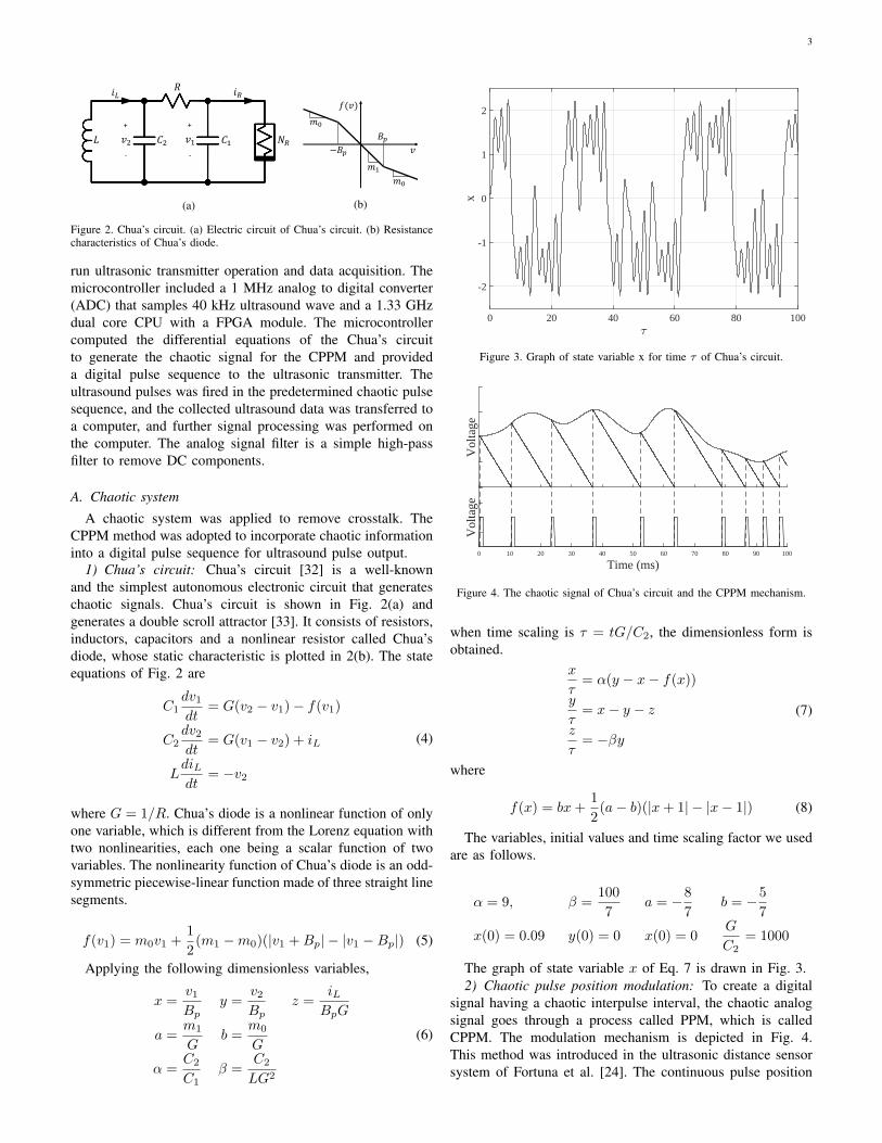
Figure 2. Chua’s circuit. (a) Electric circuit of Chua’s circuit. (b) Resistancecharacteristics of Chua’s diode.
run ultrasonic transmitter operation and data acquisition. Themicrocontroller included a 1 MHz analog to digital converter(ADC) that samples 40 kHz ultrasound wave and a 1.33 GHzdual core CPU with a FPGA module. The microcontrollercomputed the differential equations of the Chua’s circuitto generate the chaotic signal for the CPPM and provideda digital pulse sequence to the ultrasonic transmitter. Theultrasound pulses was fired in the predetermined chaotic pulsesequence, and the collected ultrasound data was transferred toa computer, and further signal processing was performed onthe computer. The analog signal filter is a simple high-passfilter to remove DC components.
A. Chaotic system
A chaotic system was applied to remove crosstalk. TheCPPM method was adopted to incorporate chaotic informationinto a digital pulse sequence for ultrasound pulse output.
1) Chua’s circuit: Chua’s circuit [32] is a well-knownand the simplest autonomous electronic circuit that generateschaotic signals. Chua’s circuit is shown in Fig. 2(a) andgenerates a double scroll attractor [33]. It consists of resistors,inductors, capacitors and a nonlinear resistor called Chua’sdiode, whose static characteristic is plotted in 2(b). The stateequations of Fig. 2 are
C1dv1dt
= G(v2 − v1)− f(v1)
C2dv2dt
= G(v1 − v2) + iL
LdiLdt
= −v2
(4)
where G = 1/R. Chua’s diode is a nonlinear function of onlyone variable, which is different from the Lorenz equation withtwo nonlinearities, each one being a scalar function of twovariables. The nonlinearity function of Chua’s diode is an odd-symmetric piecewise-linear function made of three straight linesegments.
f(v1) = m0v1 +1
2(m1 −m0)(|v1 +Bp| − |v1 −Bp|) (5)
Applying the following dimensionless variables,
x =v1Bp
y =v2Bp
z =iLBpG
a =m1
Gb =
m0
G
α =C2
C1β =
C2
LG2
(6)
=0 20 40 60 80 100
x
-2
-1
0
1
2
Figure 3. Graph of state variable x for time τ of Chua’s circuit.
Vol
tage
Time (ms)0 10 20 30 40 50 60 70 80 90 100
Vol
tage
Figure 4. The chaotic signal of Chua’s circuit and the CPPM mechanism.
when time scaling is τ = tG/C2, the dimensionless form isobtained.
x
τ= α(y − x− f(x))
y
τ= x− y − z
z
τ= −βy
(7)
where
f(x) = bx+1
2(a− b)(|x+ 1| − |x− 1|) (8)
The variables, initial values and time scaling factor we usedare as follows.
α = 9, β =100
7a = −8
7b = −5
7
x(0) = 0.09 y(0) = 0 x(0) = 0G
C2= 1000
The graph of state variable x of Eq. 7 is drawn in Fig. 3.2) Chaotic pulse position modulation: To create a digital
signal having a chaotic interpulse interval, the chaotic analogsignal goes through a process called PPM, which is calledCPPM. The modulation mechanism is depicted in Fig. 4.This method was introduced in the ultrasonic distance sensorsystem of Fortuna et al. [24]. The continuous pulse position

4
+
Chaotic signal
generator
(Chua’s circuit)
Pulse position
modulator
TX-User
40kHz sine wave
correlator
Ultrasonic pulse
transmitter
Ultrasound
receiver
Threshold
RX-User
𝑓𝑠𝑠
Subsampling
NoiseTarget
Cross-correlation
Peak detector
Distance
User processing unit
Sampling 𝑓𝑠
Figure 5. The block diagram of the proposed distance measurement method.
modulator consists of a sample-and-hold circuit and a rampgenerator. The chaotic signal is input to the PPM circuit, andthe signal is sampled and held. When the held value minusthe increasing ramp signal goes to zero, the circuit generatesa digital pulse, resets the ramp signal and performs sample-and-hold again. The chaotic information of the analog voltageis transferred into the intervals between digital pulses.
IV. SIGNAL PROCESSING
Fig. 5 shows the signal processing of the proposed measure-ment method. The transmitter section of the diagram includesthe Chua’s circuit and a PPM modulator. The receiver partconsists of ultrasound receiver, a sine wave correlator fornoise filtering and threshold for binarization. The transmittergenerates ultrasonic pulses according to the CPPM sequence.A transport delay occurs while the ultrasound emitted fromthe transmitter is reflected on the target and collected by thereceiver. The transport delay corresponds to TOF and canbe measured by cross-correlation of the two signals. Eachtransmitter and receiver part provide single-bit signal to theprocessing unit to calculate the distance. In this research, thereceiver part is configured as a sampled system for furtherstudy, but can be configured as analog circuitry as needed.
A. The 40 kHz FFT value
The FFT was used to determine whether there is an ultra-sonic signal in the voltage signal collected by the ultrasonicreceiver. The ultrasound used in this study was 40 kHz (39.4kHz for exactly). Since another frequency domain of the fullFFT is not needed in the incoming voltage signal, if only the40 kHz component is calculated, the calculation amount isvery small and can be calculated quickly. In this study, theultrasonic signal ADC speed is 1 MHz and the period of the40 kHz ultrasonic wave is 25 µs. Therefore, a new voltagevalue is obtained every 1 µs, and then the 40 kHz componentvalue of a 25 µs-long voltage signal is calculated. That is, anew value is added every 1 us, and the previous 25 values,including the new value, are convoluted with the 40 kHz sinewave. The convolution integral of 25 values is very small andcan be calculated every 1 µs. Therefore, this is the real-time40 kHz FFT value.
X40kHz = |N−1∑n=1
xn · (cos(−2πkn
N) + i sin(−2πk n
N))| (9)
Frequency (kHz)30 32 34 36 38 40 42 44 46 48 50
Ultrasonic signalAmbient noise
Figure 6. The FFT of ultrasonic signal and ambient noise.
Time (ms)0 2 4 6 8
(a) Received signal voltage (V)Time (ms)
0 2 4 6 8
(b) Processed signal
Ultrasonic signalAmbient noise
Figure 7. Comparison of voltage and 40 kHz component of ultrasonic signaland ambient noise.
where X40kHz is the amount of 40 kHz in the signal, and xnis the received voltage signal to be examined.
The parameters used in this study were
k = f × N
fs; f = 40kHz ; fs = 1MHz ; N = 25
This value only represents the intensity of the 40 kHzcomponent, so it only displays the intensity of the ultrasonicwave with other noise removed, acting as a noise filter.
1) Noise elimination: Fig. 6 and Fig. 7 show the differencebetween ultrasound signals and ambient noise in various ways.The ultrasonic signal is an echo signal reflected from a wall5 meters away. Ambient noise was collected near the roadsurface while the vehicle was running at 90 km/h. The ultra-sonic signal and noise were collected in separate experimentsand compared. For practical applications, the ultrasonic sensorsystem should be able to reject any noise while the vehicle isrunning at high speed.
Fig. 6 shows the FFT result of two signals from 30 kHz to50 kHz. The ultrasonic signal has a much higher peak valuethan the noise signal. When the 40 kHz component is analyzedin real time (Fig. 7(b)), it is easier to distinguish an ultrasoniccomponent from noise than when only the voltage value isanalyzed (Fig. 7(a)). This allows external noise, such as noisefrom the road surface, to be filtered.
5
B. Subsampling
We calculated the 40 kHz FFT value per 10 µs to reducethe amount of data. This is fss in Fig. 5 and is 100 kHzsubsampling or down sampling. The subsampling is directlyrelated to the distance measurement resolution, and the sub-sampling of 100 kHz has a measurement resolution of 1.7 mm.Subsampling is a main advantage of using single-bit signals,while analog signal analysis requires much high samplingrates. Subsampling frequency can be decided according to thedesired distance measurement resolution, such as calculatingevery 100 µs to get 17 mm distance measurement resolution.
C. Single-bit signal processing with FFT threshold
If the value of 40 kHz was larger than a threshold, we de-termined that the ultrasonic wave was received and convertedinto a single-bit signal:
High - A state in which an ultrasonic signal exists.Low - No ultrasonic signal.
In the case of ultrasonic sensors for automobiles, the largestnoise coming into the sensor is the tire-road noise. Thelower the threshold value is, the less information loss dueto the binarization of the low level signal can be minimized.Therefore, the threshold was set to a value that was just abovethe noise obtained from the experiment.
Fig. 8 illustrates the overall signal processing process. Fig.8(a) shows the reference signal, and the ultrasonic transmitteroscillates at the rising edge and emits an ultrasonic pulse (b).The transmitted ultrasonic pulses are reflected back to thetarget, echoed into the receiver (c), and the microcontrollercalculates the 40 kHz FFT value (d). Simultaneously with the40 kHz value calculation, a single-bit signal was generated bya threshold (e).
Single-bit signal processing and subsampling compress datasize. Analog 32-bits numbers can be compressed into single-bit number. In this study, a 32-bit analog signal measured at 1MHz was converted to a 100 kHz single-bit signal, resultingin 320 times memory savings.
D. Detect TOF with Cross-correlation
In a previous study [31], only the interval between thereceived signal and the previously received signal was com-pared and the uniqueness of the pulse was given to find theTOF. However, in this study, the TOF was obtained by thecross-correlation between the CPPM transmitted signal and thereceived signal. The delay, at the highest point of the cross-correlation of the two signals, is the TOF.
Fig. 8(a) and Fig. 8(e) show the single-bitted transmittedreference signal and received signal, and their cross-correlationis depicted in Fig. 9. The peak delay is 19.25 ms, which meansthat the received signal is the most similar to the referencesignal when it is delayed by that amount. Therefore, the TOFis 19.25 ms, which is the delay of the peak, and the distanceis 3.215 m according to Eq. 1 and Eq. 2. We computed atemperature correction, and the actual value measured by thelaser sensor was 3.218 m.
Since both signals are binary single-bit signals, the process-ing time can be shortened to enable real-time cross-correlation
Time (ms)10 20 30 40 50 60 70 80 90 100
01
(a) Reference signal
-100
10
(b) Transmitted signal (V)
-2
0
2
(c) Received signal (V)
(d) 40kHz FFT value
01
(e) Single-bit signal
Figure 8. Signal processing procedure.
Delay (ms)0 10 20 30 40 50 60 70 80 90 100
The
cro
ss-c
orre
latio
n fu
nctio
n
0
0.1
0.2
0.3
0.4
0.5
0.6
0.7
0.8
0.8
1X: 19.25
Figure 9. Cross-correlation function of reference signal and single-bittedreceived signal.
calculations. Single-bit multiplication can significantly reducethe total calculation cost compared with multi-bit multipli-cation [29], because cross-correlation involves a large numberof multiplications. Single-bit multiplication can be easily doneby logical operations. Therefore, cross-correlation of Fig. 8(a)and Fig. 8(e) created a better real-time performance than Fig.8(b) and Fig. 8(c).
V. CROSSTALK REJECTION SIMULATION
A simulation was performed to show how much crosstalkcould be rejected. Under the multiuser conditions, the ultra-sonic sensor system receives many more undesired ultrasonicsignals than its own transmission as shown in Fig. 10. Thetransmitted signal and the received signal were obtained fromthe experiment, and it is assumed that a crosstalk signal ofmultiusers is virtually added to the received signal. In Fig. 11,(a) to (e), the number of users increases by one. We assumedthat sensor configurations of multiusers were the same as the

6
Time (ms)0 10 20 30 40 50 60 70 80 90 100
Transmitted signal
Received signal
Figure 10. Transmitted reference signal and received signal in 5 multiusercondition.
Delay (ms)-50 -25 0 25 50
(a)
(b)
(c)
(d)
(e)
Figure 11. The cross-correlation functions of transmitted reference signal andreceived signal in multiuser situation. (a) Single user condition. (b-e) 2-5multiusers conditions.
proposed method of this research. For simplicity, neither signalhad an ultrasonic transport delay.
Fig. 11 shows the cross-correlation function in all themultiuser conditions. We investigated single user and multiuserconditions to see how clear the peak was. As the number ofusers increased as shown in Fig. 11, the peak is unclear forpeak detection which means that the possibility of false TOFdetection increases. As Fig. 11 reveals, with five or more users,the average value other than the peak due to crosstalk is morethan half. This suggests that the ultrasonic sensor constructedby the proposed method has difficulty in measuring if morethan five instances of crosstalk occurs. However, the simulationresults may vary depending on the ultrasound transmissionconfiguration of the multiuser that generates the crosstalk.
Time (s)0 1 2 3 4 5 6 7 8 9
Dis
tanc
e (m
)
0
2
4
6
8
10
12
Measured distanceReference distanceInstant measurement rate
0 1 2 3 4 5 6 7 8 9
Inst
ant m
easu
rem
ent r
ate
(Hz)
0
20
40
60
80
100
120
140
Figure 12. Distance measurement result.
VI. EXPERIMENTAL RESULTS
The hardware of the CPPM-based high measurement ratesonar sensor system was configured as shown in Fig. 1. Thetarget was a rough wall, and the ultrasonic system was installedon a vehicle and it measured the distance to the wall. Theultrasonic transmitter and receiver was attached on the frontside of the vehicle. First, the microcontroller provided theCPPM signal to the transmitter. Then the oscillated ultrasonicpulses were reflected, and the echo was collected in the micro-controller through the receiver. The subsequent process wasperformed offline. The 40 kHz component of the ultrasonicraw signal was subsampled at 100 kHz and evaluated todetermine whether an ultrasonic pulse was received, and abinary signal was generated by the evaluation. If an ultrasoundsignal was received, the TOF and distance were calculated bycross correlating the generated single-bit signal with the CPPMreference signal provided to the transmitter.
Fig. 12 shows the experimental results for the rough wall.A laser sensor (red line) was used for the reference data, andthe measured distance result of the ultrasonic sensor (bluedot) is plotted. The instant measurement rate (black line) ofevery moment is drawn. The RMS error of the measureddistance to the reference distance is 29 mm. This is sufficientmeasurement accuracy in vehicle applications.
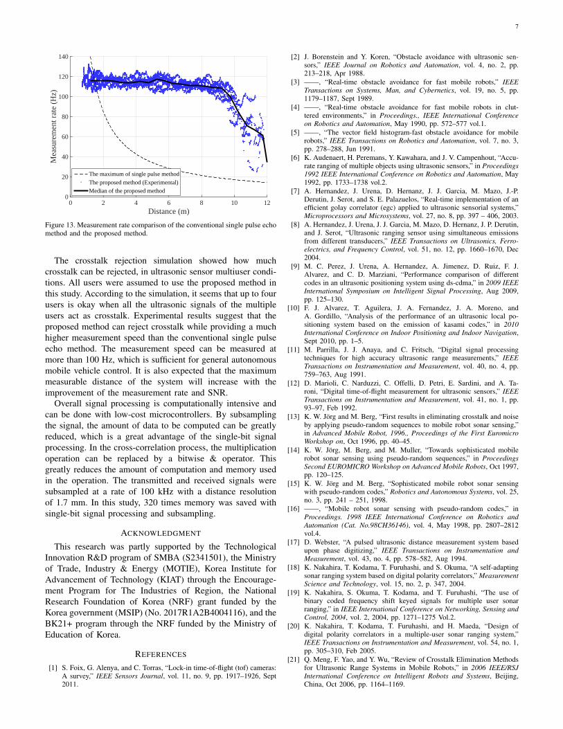
Fig. 13 summarizes the measurement rate result. The mea-surement rate of the experimental data is drawn in bluedots. The dashed line gives the ideal maximum measurementrates of the single pulse echo method. The decrease in themeasurement rate of the single pulse echo method is inverselyproportional to the distance due to rising time of flight (Eq. 3).These results show that the measurement was performed at amuch higher measurement rate than the conventional singlepulse echo method. At a distance of more than 4 m, themeasurement rate of the single pulse echo method was too lowto be used for many control applications. In normal vehiclecontrol, a measurement rate of 100 Hz or more is expected,and the proposed method meets that criteria.
Furthermore, it is also expected that the maximum measur-able distance of the ultrasonic distance sensor system will beextended. Stochastically, the proposed method can measuremore than five times more than the conventional method ataround 9 m. As the signal to noise ratio (SNR) increases at themeasurement margin, an increase of the maximum measurabledistance is expected. The experimental results show that theperformance of the system is increased by upgrading thesoftware without additional hardware.
VII. CONCLUSION
This research introduced a method for measuring distancewith crosstalk rejection at a high measurement rate using theCPPM signal and single-bit signal processing in a single ultra-sonic sensor system. To verify this, we conducted a crosstalkrejection simulation and a measurement rate experiment on awall using a sensor system installed in a vehicle. The resultsshows crosstalk rejection and high measurement rate can beachieved by the proposed method in a very low computationalload using single-bit signal processing.
7
Distance (m)0 2 4 6 8 10 12
Mea
sure
men
t rat
e (H
z)
0
20
40
60
80
100
120
140
The maximum of single pulse method
The proposed method (Experimental)
Median of the proposed method
Figure 13. Measurement rate comparison of the conventional single pulse echomethod and the proposed method.
The crosstalk rejection simulation showed how muchcrosstalk can be rejected, in ultrasonic sensor multiuser condi-tions. All users were assumed to use the proposed method inthis study. According to the simulation, it seems that up to fourusers is okay when all the ultrasonic signals of the multipleusers act as crosstalk. Experimental results suggest that theproposed method can reject crosstalk while providing a muchhigher measurement speed than the conventional single pulseecho method. The measurement speed can be measured atmore than 100 Hz, which is sufficient for general autonomousmobile vehicle control. It is also expected that the maximummeasurable distance of the system will increase with theimprovement of the measurement rate and SNR.
Overall signal processing is computationally intensive andcan be done with low-cost microcontrollers. By subsamplingthe signal, the amount of data to be computed can be greatlyreduced, which is a great advantage of the single-bit signalprocessing. In the cross-correlation process, the multiplicationoperation can be replaced by a bitwise & operator. Thisgreatly reduces the amount of computation and memory usedin the operation. The transmitted and received signals weresubsampled at a rate of 100 kHz with a distance resolutionof 1.7 mm. In this study, 320 times memory was saved withsingle-bit signal processing and subsampling.
ACKNOWLEDGMENT
This research was partly supported by the TechnologicalInnovation R&D program of SMBA (S2341501), the Ministryof Trade, Industry & Energy (MOTIE), Korea Institute forAdvancement of Technology (KIAT) through the Encourage-ment Program for The Industries of Region, the NationalResearch Foundation of Korea (NRF) grant funded by theKorea government (MSIP) (No. 2017R1A2B4004116), and theBK21+ program through the NRF funded by the Ministry ofEducation of Korea.
REFERENCES
[1] S. Foix, G. Alenya, and C. Torras, “Lock-in time-of-flight (tof) cameras:A survey,” IEEE Sensors Journal, vol. 11, no. 9, pp. 1917–1926, Sept2011.
[2] J. Borenstein and Y. Koren, “Obstacle avoidance with ultrasonic sen-sors,” IEEE Journal on Robotics and Automation, vol. 4, no. 2, pp.213–218, Apr 1988.
[3] ——, “Real-time obstacle avoidance for fast mobile robots,” IEEETransactions on Systems, Man, and Cybernetics, vol. 19, no. 5, pp.1179–1187, Sept 1989.
[4] ——, “Real-time obstacle avoidance for fast mobile robots in clut-tered environments,” in Proceedings., IEEE International Conferenceon Robotics and Automation, May 1990, pp. 572–577 vol.1.
[5] ——, “The vector field histogram-fast obstacle avoidance for mobilerobots,” IEEE Transactions on Robotics and Automation, vol. 7, no. 3,pp. 278–288, Jun 1991.
[6] K. Audenaert, H. Peremans, Y. Kawahara, and J. V. Campenhout, “Accu-rate ranging of multiple objects using ultrasonic sensors,” in Proceedings1992 IEEE International Conference on Robotics and Automation, May1992, pp. 1733–1738 vol.2.
[7] A. Hernandez, J. Urena, D. Hernanz, J. J. Garcia, M. Mazo, J.-P.Derutin, J. Serot, and S. E. Palazuelos, “Real-time implementation of anefficient golay correlator (egc) applied to ultrasonic sensorial systems,”Microprocessors and Microsystems, vol. 27, no. 8, pp. 397 – 406, 2003.
[8] A. Hernandez, J. Urena, J. J. Garcia, M. Mazo, D. Hernanz, J. P. Derutin,and J. Serot, “Ultrasonic ranging sensor using simultaneous emissionsfrom different transducers,” IEEE Transactions on Ultrasonics, Ferro-electrics, and Frequency Control, vol. 51, no. 12, pp. 1660–1670, Dec2004.
[9] M. C. Perez, J. Urena, A. Hernandez, A. Jimenez, D. Ruiz, F. J.Alvarez, and C. D. Marziani, “Performance comparison of differentcodes in an ultrasonic positioning system using ds-cdma,” in 2009 IEEEInternational Symposium on Intelligent Signal Processing, Aug 2009,pp. 125–130.
[10] F. J. Alvarez, T. Aguilera, J. A. Fernandez, J. A. Moreno, andA. Gordillo, “Analysis of the performance of an ultrasonic local po-sitioning system based on the emission of kasami codes,” in 2010International Conference on Indoor Positioning and Indoor Navigation,Sept 2010, pp. 1–5.
[11] M. Parrilla, J. J. Anaya, and C. Fritsch, “Digital signal processingtechniques for high accuracy ultrasonic range measurements,” IEEETransactions on Instrumentation and Measurement, vol. 40, no. 4, pp.759–763, Aug 1991.
[12] D. Marioli, C. Narduzzi, C. Offelli, D. Petri, E. Sardini, and A. Ta-roni, “Digital time-of-flight measurement for ultrasonic sensors,” IEEETransactions on Instrumentation and Measurement, vol. 41, no. 1, pp.93–97, Feb 1992.
[13] K. W. Jorg and M. Berg, “First results in eliminating crosstalk and noiseby applying pseudo-random sequences to mobile robot sonar sensing,”in Advanced Mobile Robot, 1996., Proceedings of the First EuromicroWorkshop on, Oct 1996, pp. 40–45.
[14] K. W. Jorg, M. Berg, and M. Muller, “Towards sophisticated mobilerobot sonar sensing using pseudo-random sequences,” in ProceedingsSecond EUROMICRO Workshop on Advanced Mobile Robots, Oct 1997,pp. 120–125.
[15] K. W. Jorg and M. Berg, “Sophisticated mobile robot sonar sensingwith pseudo-random codes,” Robotics and Autonomous Systems, vol. 25,no. 3, pp. 241 – 251, 1998.
[16] ——, “Mobile robot sonar sensing with pseudo-random codes,” inProceedings. 1998 IEEE International Conference on Robotics andAutomation (Cat. No.98CH36146), vol. 4, May 1998, pp. 2807–2812vol.4.
[17] D. Webster, “A pulsed ultrasonic distance measurement system basedupon phase digitizing,” IEEE Transactions on Instrumentation andMeasurement, vol. 43, no. 4, pp. 578–582, Aug 1994.
[18] K. Nakahira, T. Kodama, T. Furuhashi, and S. Okuma, “A self-adaptingsonar ranging system based on digital polarity correlators,” MeasurementScience and Technology, vol. 15, no. 2, p. 347, 2004.
[19] K. Nakahira, S. Okuma, T. Kodama, and T. Furuhashi, “The use ofbinary coded frequency shift keyed signals for multiple user sonarranging,” in IEEE International Conference on Networking, Sensing andControl, 2004, vol. 2, 2004, pp. 1271–1275 Vol.2.
[20] K. Nakahira, T. Kodama, T. Furuhashi, and H. Maeda, “Design ofdigital polarity correlators in a multiple-user sonar ranging system,”IEEE Transactions on Instrumentation and Measurement, vol. 54, no. 1,pp. 305–310, Feb 2005.
[21] Q. Meng, F. Yao, and Y. Wu, “Review of Crosstalk Elimination Methodsfor Ultrasonic Range Systems in Mobile Robots,” in 2006 IEEE/RSJInternational Conference on Intelligent Robots and Systems, Beijing,China, Oct 2006, pp. 1164–1169.
8
[22] J. Borenstein and Y. Koren, “Noise rejection for ultrasonic sensors inmobile robot applications,” in Proceedings 1992 IEEE InternationalConference on Robotics and Automation, May 1992, pp. 1727–1732vol.2.
[23] ——, “Error eliminating rapid ultrasonic firing for mobile robot obstacleavoidance,” IEEE Transactions on Robotics and Automation, vol. 11,no. 1, pp. 132–138, Feb 1995.
[24] L. Fortuna, M. Frasca, and A. Rizzo, “Chaos preservation throughcontinuous chaotic pulse position modulation,” in ISCAS 2001. The2001 IEEE International Symposium on Circuits and Systems (Cat.No.01CH37196), vol. 3, May 2001, pp. 803–806 vol. 2.
[25] ——, “Chaotic Pulse Position Modulation to Improve the Efficiency ofSonar Sensors,” IEEE Transactions on Instrumentation and Measure-ment, vol. 52, no. 6, pp. 1809–1814, Dec 2003.
[26] Z. J. Yao, Q. H. Meng, G. W. Li, and P. Lin, “Non-Crosstalk Real-Time Ultrasonic Range System with Optimized Chaotic Pulse Position-Width Modulation Excitation,” in 2008 IEEE Ultrasonics Symposium,Nov 2008, pp. 729–732.
[27] Q. H. Meng, S. Y. Lan, Z. J. Yao, and G. W. Li, “Real-Time Non-crosstalk Sonar System by Short Optimized Pulse-Position ModulationSequences,” IEEE Transactions on Instrumentation and Measurement,vol. 58, no. 10, pp. 3442–3449, Oct 2009.
[28] F. Alonge, M. Branciforte, and F. Motta, “A novel method of distancemeasurement based on pulse position modulation and synchronizationof chaotic signals using ultrasonic radar systems,” IEEE Transactionson Instrumentation and Measurement, vol. 58, no. 2, pp. 318–329, Feb2009.
[29] S. Hirata, M. K. Kurosawa and T. Katagiri, “Cross-Correlation bySingle-bit Signal Processing for Ultrasonic Distance Measurement,”IEICE Transactions on Fundamentals of Electronics, Communicationsand Computer Sciences, vol. E91-A, no. 4, pp. 1031–1037, Apr 2008.
[30] S. Hirata, M. K. Kurosawa, and T. Katagiri, “Real-time ultrasonicdistance measurements for autonomous mobile robots using cross cor-relation by single-bit signal processing,” in 2009 IEEE InternationalConference on Robotics and Automation, Kobe, Japan, May 2009, pp.3601–3606.
[31] S. Shin, M. H. Kim, and S. B. Choi, “Improving efficiency of ultra-sonic distance sensors using pulse interval modulation,” in 2016 IEEESENSORS, Oct 2016, pp. 1–3.
[32] R. N. Madan, Chua’s circuit: a paradigm for chaos. World Scientific,1993, vol. 1.
[33] T. Matsumoto, L. Chua, and M. Komuro, “The double scroll,” IEEETransactions on Circuits and Systems, vol. 32, no. 8, pp. 797–818, Aug1985.
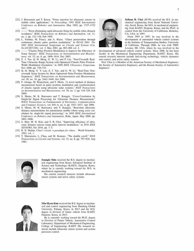
Seungin Shin received the B.S. degree in mechan-ical engineering from Korea Advanced Institute ofScience and Technology (KAIST), Deajeon, Korea,where he is curretly working toward his M.S. inmechanical engineering.
His current research interests include ultrasonicsensor systems and active safety systems.
Min-Hyun Kim received the B.S. degree in mechan-ical and control engineering from Handong GlobalUniversity, Pohang, Korea, in 2013 and the M.S.degree in division of future vehicle from KAIST,Daejeon, Korea, in 2015.
He is currently working toward the Ph.D. degreein Division of Future Vehicle, Automotive ControlLaboratory, Department of Mechanical Engineering,College of Engineering, KAIST. His research in-terests include ultrasonic sensor system and systemprecision control.
Seibum B. Choi (M’09) received the B.S. in me-chanical engineering from Seoul National Univer-sity, Seoul, Korea, the M.S. in mechanical engineer-ing from KAIST, Deajeon, Korea, and the Ph.D. incontrol from the University of California, Berkeley,CA, USA, in 1993.
From 1993 to 1997, he was involved in thedevelopment of automated vehicle control systemsat the Institute of Transportation Studies, Universityof California. Through 2006, he was with TRW,Livonia, MI, USA, where he was involved in the
development of advanced vehicle control systems. Since 2006, he has beenfaculty in the Mechanical Engineering Department, KAIST, Korea. Hiscurrent research interests include fuel-saving technology, vehicle dynamicsand control, and active safety systems.
Prof. Choi is a Member of the American Society of Mechanical Engineers,the Society of Automotive Engineers, and the Korean Society of AutomotiveEngineers.


![Ultrasonic Based Distance Measurement System - News · PDF fileEE616 Electronic Design Lab Project Report, ... [2] K. J. Ayala, 8051 Microcontroller, ... GAIN AMPLIFIER ULTRASONIC](https://img.dokumen.tips/doc/110x75/5a700db87f8b9abb538b95a5/ultrasonic-based-distance-measurement-system-newswww8051projectsnetfilespublic133794617138097ft0reportpdfpdf.jpg)