Embed Size (px)
Citation preview

2001 SENSORS02_5
MECH4720 SENSORS & SIGNALS 1of18
VISIBLE IMAGING & IMAGE INTENSIFIERS
HUMAN VISION � Electro-optical sensors for use by human operators must match the
performance of the human eye to be effective. This includes the following: � The mechanics of light detection � Processing of spatial information by the retina � Interpretation and analysis of visual information by the brain
2001 SENSORS02_5
MECH4720 SENSORS & SIGNALS 2of18
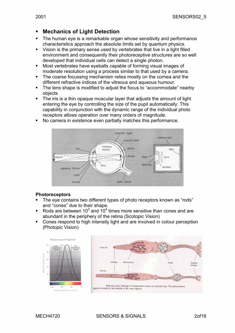
� Mechanics of Light Detection � The human eye is a remarkable organ whose sensitivity and performance
characteristics approach the absolute limits set by quantum physics. � Vision is the primary sense used by vertebrates that live in a light filled
environment and consequently their photoreceptive structures are so well developed that individual cells can detect a single photon.
� Most vertebrates have eyeballs capable of forming visual images of moderate resolution using a process similar to that used by a camera.
� The coarse focussing mechanism relies mostly on the cornea and the different refractive indices of the vitreous and aqueous humour.
� The lens shape is modified to adjust the focus to “accommodate” nearby objects
� The iris is a thin opaque muscular layer that adjusts the amount of light entering the eye by controlling the size of the pupil automatically. This capability in conjunction with the dynamic range of the individual photo receptors allows operation over many orders of magnitude.
� No camera in existence even partially matches this performance.
Photoreceptors � The eye contains two different types of photo receptors known as “rods”
and “cones” due to their shape. � Rods are between 103 and 104 times more sensitive than cones and are
abundant in the periphery of the retina (Scotopic Vision) � Cones respond to high intensity light and are involved in colour perception
(Photopic Vision)

2001 SENSORS02_5
MECH4720 SENSORS & SIGNALS 3of18
Photoreceptor Response � Different cone cells contain different pigments and so respond to different
wavelengths of light. References are not entirely consistent with regard to these spectral responses with the peak sensitivity varying as follows: � Blue cones 420-455nm � Green cones 530-540nm � Red cones 580-625nm
� The peak sensitivity of rod cells lies at about 510nm
� Solar emission peaks at about 500nm (green light) which coincides with
the maximum sensitivity of the eye (as you would expect). The figure below shows the direct solar irradiance for the sun directly overhead.
� As the sun moves from the zenith, the contribution to scene illumination from light scattered by the atmosphere becomes more significant. For objects in the shade, this is the major source of illumination.
� The peak emission from scattered light is in the blue part of the spectrum for which the human eye is much less colour sensitive as shown in the threshold responses above.

2001 SENSORS02_5
MECH4720 SENSORS & SIGNALS 4of18
Light Detection Mechanism � A complex chemical reaction known as the Rodopsin cycle takes place
every time a photo receptor cell is stimulated by light of the correct frequency. This process triggers a generator potential which is transmitted to the connecting neuron.
� A second reaction must then take place to restore the chemical balance before the cell is again sensitive to light.
Rhodopsin
LightEnergy Scotopsin Retinene Energy
Vitamin A
Rhodopsin Scotopsin Retinene
Vitamin A
Energyfrom ATP
+ +
+
Triggersgeneratorpotential
Spatial Response of the Retina
� The fovea centralis (also known as the macular depression) is a funnel shaped depression which is tightly packed with cone cells,
� In human beings there are about 150,000 per square millimetre.
� The fovea produces the most acute vision and so vertebrates tend to track objects to keep them centred in this region.
� Outside the area of the Fovea are the rod receptors and less densely packed cones. Rod density increases to a maximum at an angle of about 20° off the visual axis, then decreases as shown in the figure below

2001 SENSORS02_5
MECH4720 SENSORS & SIGNALS 5of18
� Contrary to the classical analogy that regards the eye as a camera, the optic nerve does not convey information from each light sensitive cell to the brain as much of the processing occurs in the groups of nerve (ganglion and bipolar) cells that form a matrix of interconnections with the photo receptor cells distributed across the retina. � The photoreceptor cells actually communicate through three distinct
layers of bipolar cells before connection to the ganglion cells which respond according to a certain receptive field.
� Orientation selective receptive fields contain an excitatory lobe on one side and an inhibitory lobe on the other so as to form an asymmetric field. These groups of cells exist over a wide variety of orientations.
� Even and odd symmetric receptive fields respond strongly to luminance edges and line features in images respectively.
� More complex receptive fields that combine the responses of the even and odd symmetric responses in a non-linear fashion exist to process more complex features.
� End stopped cells appear to act as simple differentiators � The following views of the retina gives an indication of the complexity of
this structure
� There are no light sensitive cells where the optic nerve exits the eyeball.
This region is known as the “blind spot”.
TELEVISION
� Nipkow and mechanically scanned television Until the advent of electronic scanning, all workable television systems depended on some form or variation (e.g., mirror drums, lensed disks, etc.) of the mechanical sequential scanning method exemplified by the Nipkow disk.

2001 SENSORS02_5
MECH4720 SENSORS & SIGNALS 6of18
As the disk rotates, the outermost aperture traces out a line across the top of the image, and the light passing through the aperture varies in direct proportion to the intensity of that line of the image as it is traversed by the aperture. When the outermost aperture has passed over the image, the next inner aperture traces out another line, parallel to and immediately below the line just traced. As the disk continues to rotate, successive lines are traced out, one beneath the other, until the whole area of the image has been explored, one line at a time
The information from a single photocell placed behind the scanner is transmitted to a receiver where it modulates a light source placed behind a similar disc synchronised to the first.
� Swinton, before his time In 1911, the Scottish electrical engineer, Campbell Swinton, outlined a method that is the basis of modern television. He proposed the use of cathode-ray tubes, magnetically deflected, at both camera and receiver. In the former was a mosaic screen of photoelectric elements onto which the image of the scene was focussed. Elements were discharged sequentially by a cathode-ray beam tracing out a line-by-line scanning sequence. These ideas were too advanced for early application, and it was left to others to put them into practice many years later.
� Baird making it work Some of the earliest recorded images made by Baird are shown in the following sequence. It shows a hand moving the ventriloquists dummy that he often used as a subject.
In 1926, Baird gave the first demonstration of true television by electrically transmitting moving pictures in halftones. These pictures using the scanning disc technique were formed of only 30 lines and repeating approximately 10 times per second. These crude results, flickering badly and with a dim receiver screen a few inches high became the start of television as a practical technology and did much to stimulate further research.

2001 SENSORS02_5
MECH4720 SENSORS & SIGNALS 7of18
� Zworykin and the all electronic television Although mechanical systems were with difficulty made to operate on 200 and more lines they were not robust and the research focus was turned to electronic methods. In 1923 Zworykin patented the iconoscope camera tube which he later constructed. In 1932 the Radio Corporation of America (RCA), with an improved cathode-ray tube for the receiver, demonstrated all-electronic television (initially on 120 lines), so proving the soundness of Swinton's theoretical ideas.
� Evolution of TV Cameras The Iconoscope
A uniform metallic coating, called the signal plate, is placed on the rear surface of a mica sheet away from the image within an evacuated chamber as shown in the diagram. The front surface of the mica is covered with a mosaic composed of an array of tiny globules of silver treated with caesium vapour and oxygen, so that each globule has a surface of the oxides of silver and caesium. This combination of elements provides a surface from
which electrons are easily liberated, by the external photoelectric effect. The globules become small capacitors that hold a charge proportional to the light intensity and exposure time.

2001 SENSORS02_5
MECH4720 SENSORS & SIGNALS 8of18
When the electron beam scans the mosaic a small current flows from the signal plate that is proportional to the charge (and hence light intensity) on each globule. Technical advances in tube design (e.g., the image orthicon and the Vidicon, the latter of which was at last able effectively to exploit the photoconductivity principle) have been continuous since that time. It is only in the past decade that the performance of solid state charge-coupled devices (CCD’s) has surpassed that of the Vidicon for some applications. The Image Orthicon This tube is housed in a cylindrical glass structure on one end of which the optical image is focussed on a mosaic made up of a precise array of squares of photosensitive material. A transparent metal coating on the reverse side serves as the signal plate. The optical image passes through signal plate to the mosaic where it creates and stores a positive electrical charge image. The low velocity electron beam scans over the mosaic in the standard interlaced scanning pattern where they land on the mosaic and neutralise the image induced stored charge and ultimately build up a negative charge. The electrons in the beam are then repelled and return to the opposite end of the tube, where they are removed by a positive collecting electrode that surrounds the electron gun. The change in electrical potential, undergone by each mosaic element as its charge is neutralised, is transferred by capacitive action to the signal plate.
The Vidicon This tube is substantially smaller than the image orthicon and hence more adaptable to portable cameras. A transparent metallic coating serves as a signal plate onto which is deposited a photoconductive material. The optical image is focussed on the end of the tube and passes through the signal plate to the photoconductive layer, where the light induces a pattern of varying conductivity that matches the distribution of brightness in the optical image. The conduction paths through the layer allow positive charge from the signal plate (which is maintained at a positive voltage) to pass through the layer, and this current continues to flow during the interval between scans. Charge storage thus occurs, and an electrical charge image is built up on the rear surface of the photoconductor. An electron beam, deflected in the standard

2001 SENSORS02_5
MECH4720 SENSORS & SIGNALS 9of18
interlaced scanning pattern, scans the rear surface of the photoconducting layer. The beam electrons neutralise the positive charge on each point in the electrical image, and the resulting change in potential is transferred by capacitive action to the signal plate, from which the television signal is derived. The electron beam scanning spot size imposes the only limit on the image detail. It is possible to derive an image of broadcast quality (200,000 or more picture elements) from a photosensitive area no larger than 1.3cm2. This is 15000 pixels per mm2 which is still far short of the resolution of the eye. The internal structure of the tube is very simple, and this, with its small size, makes it adaptable to a wide range of camera arrangements in broadcasting, industrial, and military applications.
� THE CHARGE COUPLED DEVICE (CCD) The charge-coupled device uses an array of light sensitive detector elements on a silicon chip. When a photon strikes the sensitive element, electrons are released and stored as a charge in a metal oxide semiconducter (MOS) capacitor. The chip also contains integrated microcircuitry required to transfer the detected signal along a row of discrete picture elements (or pixels) and thereby scan the image very rapidly.
When individual pixels are arranged in a row, the detector is referred to as a linear array. When the pixels are arranged in rows and columns, it is called a two-dimensional array. Pixels can be assembled in various sizes and shapes.

2001 SENSORS02_5
MECH4720 SENSORS & SIGNALS 10of18
The Hubble Space Telescope has a CCD detector with a 1,600x1,600 pixel array made up of four 800x800 pixel arrays in a mosaic. The sensitivity of a CCD is about 100 times greater than a photographic plate and so has the ability to quickly scan objects in low light conditions. It is particularly useful in astronomy. Another feature of the CCD is that the detector material may be altered to provide more sensitivity at different wavelengths. Thus, some detectors are more sensitive in the blue region of the spectrum than in the red region. CCD’s can be cryogenically cooled to improve their sensitivity to IR signals.
Most modern video cameras use half-inch CCD arrays that contain between 400,000 and 1,000,000 pixels. This is between 155 and 390 pixels per mm2 (compared to 150000 for the human eye) The advent of high-resolution CCD arrays has lead to a new generation of still cameras. At the time of writing, one of the most advanced is the Kodak DCS-560 which advertises a colour mosaic 3040x2008 pixels (6M pixels). Its CCD is based on Indium Tin Oxide (InSnO) that gives a good blue light sensitivity. Micro lenses above the mosaic blend the colours to the pixels
� CMOS ARRAYS Low cost video and still camera applications generally use CMOS arrays as they cheap to manufacture using standard lithographic processes and produce images with adequate resolution. A company called Foveon has just released a camera based on a 0.18micron CMOS process (most other processes are either 0.3 or 0.5micron) that advertises a 4096x4096 array (16.8M pixels) on a 22x22mm substrate. � The chip contains 22million transistors � ISO speed 100 � Dynamic range 10 stops � Shutter 2s to 1/8000sec

2001 SENSORS02_5
MECH4720 SENSORS & SIGNALS 11of18
The pixel density is still only 35000 per mm2 which is about one quarter as good as the human eye!
� IMAGE INTENSIFIERS Image intensifiers are passive sensors that amplify ambient visible and near infrared radiation. The scene is imaged onto a photocathode, much as would happen with a Vidicon tube, however in an image intensifier the energy band structure of the photocathode material is such that on absorption of light, electrons are emitted from the surface. At best one electron can be emitted per photon 1st Generation Tubes In first generation devices, these electrons are focussed and accelerated by an electric field before they impact on a luminescent screen. Because the accelerated electrons posses increased energy, each electron gives rise to many photons (in the visible part of the spectrum) when it is absorbed by the phosphor.
To maintain crisp images, the distance travelled by each electron is limited, this limits the distance between the electrodes, and hence the allowed acceleration voltage is not very high. Single stage devices offer gains of between 50 and 100 which gives satisfactory performance down to moonlight illumination levels. For starlight levels, gains of >50000 are required. This is achieved by cascading multiple stages.
Condition Illumination (lux) Condition Illumination (lux) Direct sunlight 105 Deep twilight 1 Full daylight 104 Full moon 10-1
Overcast day 103 Quarter moon 10-2
Very dark day 102 Clear starlight 10-3
Twilight 10 Overcast starlight 10-4

2001 SENSORS02_5
MECH4720 SENSORS & SIGNALS 12of18
2nd Generation Tubes Second generation tubes use a micro channel plate (MCP) between the photocathode and the phosphor. The early MCP’s consisted of about a million hollow glass tubes fused together into a disc. These tubes are about 10µm in diameter and 1mm long. The inside walls of the individual tubes are coated with a secondary emitting material and so act as electron multipliers. A single stage tube with a MCP can produce gains of up to 5x10⁴. Modern MCP’s contain between 2 and 6 million holes. This number is a major factor in determining resolution

2001 SENSORS02_5
MECH4720 SENSORS & SIGNALS 13of18

2001 SENSORS02_5
MECH4720 SENSORS & SIGNALS 14of18
These photomicrographs show an early microchannel plate that was manufactured in the late 1980’s. Limitations of Microchannel Plates Four major physical constraints limit their performance:
� Average output signal cannot exceed the maximum current that can be sustained within the walls of the microchannel. When the electron flux is too large, electric charge removed from the glass is not replaced immediately and the gain is reduced. Bright parts of an image can saturate and lose contrast
� If one of the molecules of gas that remain in the tube becomes ionised, it becomes accelerated towards the input of the tube where it could strike the wall and initiate a new cascade of electrons. This cascade can mask the signal. Curved microchannel paths minimise this effect
� The charge density of electrons in the tube is limited to about 107 per mm before mutual electrostatic repulsion returns additional secondary electrons to the surface of the channel before the field can accelerate them.
� The surface area of the channels is less than the surface area of the entire plate. Geometric constraints limit this to a maximum of 91%, but because the walls must be a finite thickness, this is generally worse (typically about 55%). This means that about half of the input flux hits the area between the channels. Channels can be made funnel shaped to minimise this effect.
3rd Generation Tubes Third generation tubes are similar in construction to 2nd generation devices but have a GaAs photocathode which is more sensitive and extends into the near infrared (NIR) band (450 to 950nm).

2001 SENSORS02_5
MECH4720 SENSORS & SIGNALS 15of18
2001 SENSORS02_5
MECH4720 SENSORS & SIGNALS 16of18
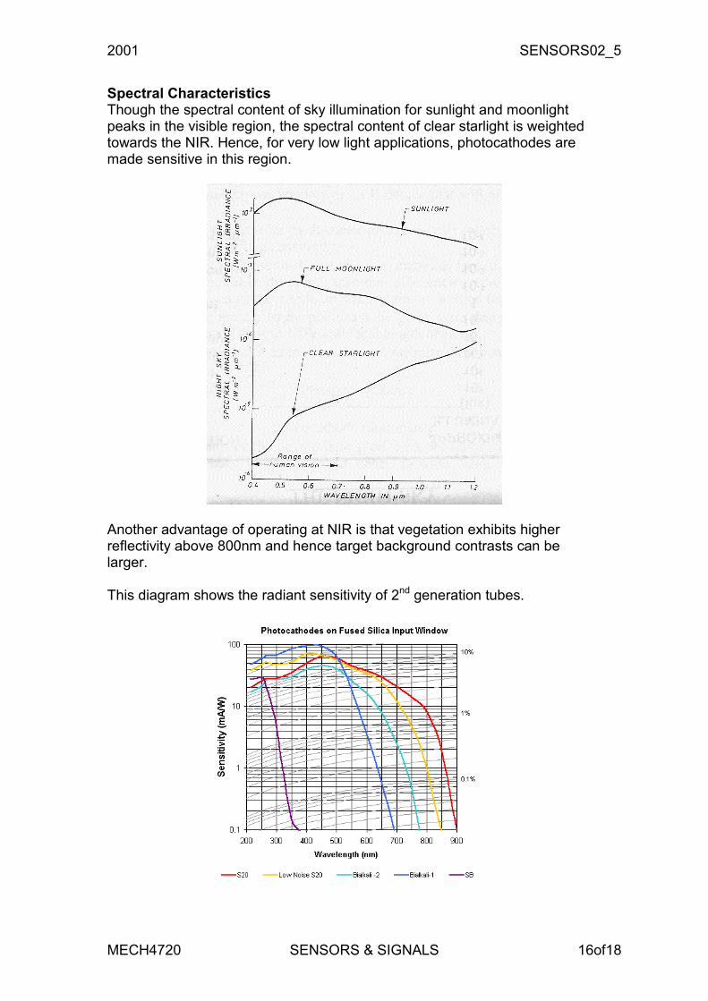
Spectral Characteristics Though the spectral content of sky illumination for sunlight and moonlight peaks in the visible region, the spectral content of clear starlight is weighted towards the NIR. Hence, for very low light applications, photocathodes are made sensitive in this region.
Another advantage of operating at NIR is that vegetation exhibits higher reflectivity above 800nm and hence target background contrasts can be larger. This diagram shows the radiant sensitivity of 2nd generation tubes.
2001 SENSORS02_5
MECH4720 SENSORS & SIGNALS 17of18
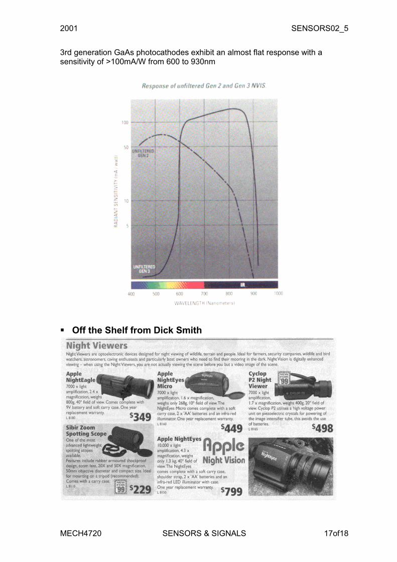
3rd generation GaAs photocathodes exhibit an almost flat response with a sensitivity of >100mA/W from 600 to 930nm
� Off the Shelf from Dick Smith

2001 SENSORS02_5
MECH4720 SENSORS & SIGNALS 18of18
� References [1] S.A.Miller and J.P.Harley, Zoology, Wm.C.Brown, 1991 [2] K.Sabbagh and C.Barnard, The Living Body, Flower Press, 1987 [3] C.Mueller and M.Rudolph, Light and Vision, Time Life International, 1972. [4] http://www.dai.ed.ac.uk/Cvonline/LOCAL_COPIES/OWENS/LECT1/node2.html. 18/02/2001. [5] E.H.Land, The Retinex Theory of Colour Vision, Scientific American, December 1977. [6] Jacob Fraden, Handbook of Modern Sensors 2nd Ed., AIP Press, 1996 [7] Duncan W Craig, RSAF Platform Engineers Course: Electro-Optics Module., DSTO, August 1994 [8] Encyclopaedia Britannica, Standard CD, 2000 [9] Sunday Telegraph (Sydney), 04/02/2001 [10] M.Lampton, The Microchannel Image Intensifier, Scientific American, November 1981 [11] http://www.x20.org/nightvision/nightvisionTHEORY.HTML, 17/02/2000. [12] http://foveon.net/press_16megapix.html