Embed Size (px)
Citation preview

VisiMix Turbulent. Example 7.
VISIMIX TURBULENT. COOLING OF A REACTOR WITH HALF-PIPE COIL FOR PRODUCTION OF
PROPYLENE GLYCOL. RELEASE OF REPORT. This example demonstrates VisiMix capabilities in simulating industrial processes controlled by exothermal reaction. An example of such a process is borrowed from the book of H. Scott Fogler, Elements of Chemical Reaction Engineering, 2nd ed. (Prentice-Hall, Inc. 1992), pp. 400 - 405, Examples 8-4 and 8-5. Problem description: Propylene glycol (PG) is produced by the hydrolysis of propylene oxide (PO). The reaction takes place at room temperature when catalyzed by sulfuric acid.
PO + H O PG2H SO2 4 →
In accordance with the technological requirements, 2500 lb/h (43.03 lb-mole/h) of PO is fed to the reactor. The feedstream consists of (1) a mixture of equal volumes of PO (46.62 ft3/h) and methanol (46.62 ft3/h), and (2) water containing 0.1 mass percent of H2SO4. The volumetric flow rate of water is 233.1 ft3/h, which is 2.5 times methanol - PO flow rate. The corresponding molar feed rates of methanol and water are 71.87 and 802.8 lb-mole/h, respectively. The inlet temperature of all feedstreams is 75°F. The reaction under consideration is first-order in PO concentration, and apparent zero-order in excess of water with the specific reaction rate k = A e -E/RT = 16.96 * 10 12 (e -32400/RT) h-1 (1)
In this equation, E is measured in Btu/lb-mole.
The process has an important operating constraint. The temperature of the mixture must not exceed 130°F because of the low boiling point of PO. The task is to determine whether this process can be carried out in a glass-lined continuos-stirred 300-gal reactor. You must design an appropriate jacketed tank corresponding to this capacity and to the temperature limit above, perform simulation and determine the PO-PG conversion. Preliminary considerations In order to enter the required initial data, you must perform the following calculations: Volume of media is 300 gal = 40.1 ft3. All flow rate values are presented below in Table 1.

VisiMix Turbulent. Example 7. 2
Material Volumetric Flow Rate,
ft3/h Mole Flow Rate, lb-mole/h
PO 46.62 43.03 Methanol 46.62 71.87 Water 233.1 802.8
Table 1. Flow rates. Total volumetric flow rate: 46.62 + 46.62 + 233.1 = 326.34 ft3/h; VisiMix considers exothermal second order reactions only. It means that the A factor, equal to 16.96 * 10 12 (see Eq. 1 for specific reaction rate k ) and corresponding to the case when the reaction is first-order with regard to the PO concentration, and apparent zero-order with regard to water excess, must be transformed into Anew. Initial concentration of reactant A (PO): 43.03 lb-mole/h / 326.34 ft3/h = 0.1319 lb-mole/ft3 (2.1128 mole/liter); Initial concentration of reactant B (water): 802.8 lb-mole/h / 326.34 ft3/h = 2.46 lb-mole/ft3 (39.404 mole/liter); Anew = A / 2.46 = 16.96 * 1012 / 2.46 = 6.894 * 1012 ft3/ lb-mole/h (1.1964*108 liter/mole/sec). Heat effect of reaction: 36540 Btu/lb-mole (85000 J/mole). The process is simulated as a steady state of the transient occurring in the following conditions. The reactor is filled with water which is then expelled by two components: reactant A (PO with flow rate equal 46.62 ft3/h) and reactant B, which is actually a mixture of methanol (46.62 ft3/h) and water containing 0.1 mass percent of H2SO4 (233.1 ft3/h). The properties of reactant B are close to those of ordinary water, and therefore you should enter water properties in the input tables. The Solution: The general sequence of operations is as follows: you must start a new project file for your case, select your equipment from the graphical menus, enter the initial data requested by the program, and then select the parameter/s for calculation from the Calculate menu. The program will then request additional data required for the modeling, and when all this data has been entered, you will obtain the result, presented as a table or a graph. In your case of a continuous flow reactor, you must select Heat transfer. Continuous Flow (CF) option in the Calculate menu, and calculate the following parameters: Media temperature, to ensure that the temperature of the mixture does not exceed 130°F, and Concentration of reactant A (PO) required to calculate the conversion value.

VisiMix Turbulent. Example 7. 3
After installing VisiMix, the main menu shown in Figure 7-1 appears. Select Project-New.
Figure 7-1. VisiMix main menu. A dialogue shown in Figure 7-2 will appear. Enter a name for your project, for example PG-Production, and save it in any convenient directory, for example, tutorial.
Figure 7-2. Starting a new project. After you click Save, the Tank types menu with tanks differing by bottom type (flat, conical and elliptical) and type of heat transfer device (unjacketed tanks, tanks with conventional, half-pipe coil, and embossed/dimpled jackets) appears. Click on the

VisiMix Turbulent. Example 7. 4
diagram of your tank with elliptical bottom and half-pipe coil jacket, and it will appear in the Current choice window on the right (Figure 7-3).
Figure 7-3. VisiMix graphic tanks selection. Click OK to confirm your choice, and TANK WITH ELLIPTICAL BOTTOM input table with the selected tank diagram appears. Enter the Inside diameter, Total tank height, and Volume of media for your available 300-gal reactor. The Total volume and Level of media will be calculated by the program and entered automatically (Figure 7-4). Click OK to confirm your input.
Figure 7- 4. Entering tank data.

VisiMix Turbulent. Example 7. 5
After you click OK, the Baffle types menu with different baffles (without baffles, two types of flat baffles and two types of tubular ones) appears. To choose the required baffle type, click on the appropriate baffle diagram. Let us select a flat baffle attached to the wall (Flat baffle 1), and it will appear in the Current choice window on the right (Figure 7-5). Click OK to confirm your choice
Figure 7-5. VisiMix graphic baffle selection. Now you have to enter all your baffle data in FLAT BAFFLE-1 input table that appears (Figure 7-6).
Figure 7-6. Entering baffle data.

VisiMix Turbulent. Example 7. 6
Click OK to confirm your input, and Impeller types menu appears. Choose your single-stage pitched paddle impeller by clicking on the appropriate diagram, and on the single option in the Current choice window on the right (Figure 7-7). Click OK to confirm your choice. You will now be asked to complete PITCHED PADDLE input table (Figure 7-8).
Figure 7-7. VisiMix graphic impeller selection.

VisiMix Turbulent. Example 7. 7
Figure 7-8. Entering impeller data. Click OK to confirm your input, and TANK HEAT TRANSFER GENERAL DATA input table appears (Figure 7-9). Note that for your single-sectioned jacket, only those parameters that refer to the lower jacket section will be active. The completed table will include the following data regarding the jacketed tank design:
Tank head type Elliptical Jacket covers bottom: Yes Number of jacket sections: 1 Height, Hlow (mm): 1000

VisiMix Turbulent. Example 7. 8
Figure 7-9. Entering general jacket characteristics. You will then be asked to enter average properties of media including DENSITY AND TYPE OF MEDIA input table (Figure 7-10a) and AVERAGE VISCOSITY OF MEDIA input table (Figure 7-10b).
Figure 7-10a. Density and type of media.

VisiMix Turbulent. Example 7. 9
Figure 7-10b. Average viscosity of media. After this table has been completed, the diagram of your mixing system corresponding to the data you have entered appears (Figure 7-11). We recommend closing this window before proceeding to calculations. If at any stage of your working on a project you will need the diagram of your apparatus, click on the quick access button in the upper screen bar.
Figure 7-11. Drawing of apparatus. Now when all basic initial data has been entered, you can start the calculations. For your reactor, you must select Heat Transfer. Continuous Flow (CF) - Liquid agent (LA) option in the Calculate menu. As mentioned before, you need to calculate Media temperature and Concentration of reactant A. Click on Media temperature. For calculating this parameter, additional data is needed, and the program will request it by invoking the appropriate input tables. First you will be asked to complete HEAT TRANSFER. CHEMICAL REACTION DATA AND TEMPERATURE LIMITS (Figure 7-12). Upper temperature limit is 130° F as mentioned above.
VisiMix Turbulent. Example 7. 10
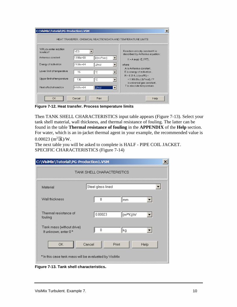
Figure 7-12. Heat transfer. Process temperature limits Then TANK SHELL CHARACTERISTICS input table appears (Figure 7-13). Select your tank shell material, wall thickness, and thermal resistance of fouling. The latter can be found in the table Thermal resistance of fouling in the APPENDIX of the Help section. For water, which is an in-jacket thermal agent in your example, the recommended value is
0.00023 (m2⋅K)/W. The next table you will be asked to complete is HALF - PIPE COIL JACKET. SPECIFIC CHARACTERISTICS (Figure 7-14)
Figure 7-13. Tank shell characteristics.

VisiMix Turbulent. Example 7. 11
Figure 7-14. Half-pipe coil jacket. Specific characteristics. After this table has been completed, HEATING / COOLING LIQUID AGENT IN JACKET input table appears (Figure 7-15), and then HEAT TRANSFER PROPERTIES OF THE MEDIA input table (Figure 7-16)..
Figure 7-15. Heating/cooling liquid agent in jacket.
VisiMix Turbulent. Example 7. 12
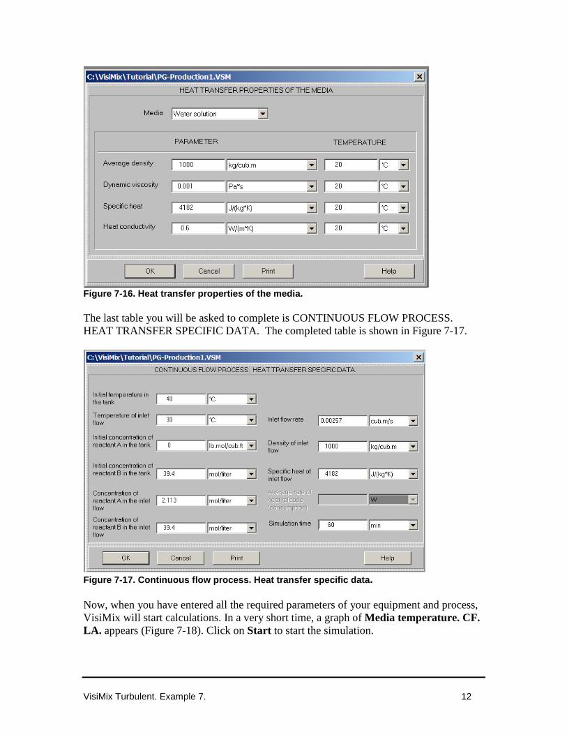
Figure 7-16. Heat transfer properties of the media. The last table you will be asked to complete is CONTINUOUS FLOW PROCESS. HEAT TRANSFER SPECIFIC DATA. The completed table is shown in Figure 7-17.
Figure 7-17. Continuous flow process. Heat transfer specific data. Now, when you have entered all the required parameters of your equipment and process, VisiMix will start calculations. In a very short time, a graph of Media temperature. CF. LA. appears (Figure 7-18). Click on Start to start the simulation.

VisiMix Turbulent. Example 7. 13
Figure 7-18. Media temperature. CF. LA.
From this graph, you can see that your process requirement is met: the temperature does not reach 130° F (54.55 °C).
You must now check the conversion factor. The conversion is estimated as concentration of PG divided by concentration of PO, that is the difference between the initial concentration of reactant A in the inlet flow and the final concentration of reactant A as calculated by VisiMix, divided by the initial concentration of reactant A in the inlet flow.
To obtain final concentration of reactant A, click on Last menu in the main menu and select Concentration of reactant A. CF. LA. You will obtain a graph shown in Figure 7-19. Click on Start to start the simulation, and from the curve that appears take the concentration value (0.85 in your case). Therefore, the conversion factor can be calculated as follows:
6.0113.2
85.0113.2 =−=−
POin
POPOin
C
CC
where CPOin is concentration of PO (reactant A) in the inlet flow, and CPO is final concentration of PO (reactant A) in the reactor.
Figure 7-19. Concentration of reactant A. CF. LA.

VisiMix Turbulent. Example 7. 14
If you want to check the effect of other process parameters, click on Last menu, and select the required parameters. Some of the calculated results are shown below in Figs 7-20—7-22.
Figure 7-20. Concentration of reactant B. CF. LA.
Figure 7-21. Outlet temperature of LA in lower jacket. CF.
Figure 7-22. Pressure head on the jacket, maximum value.
VisiMix Turbulent. Example 7. 15
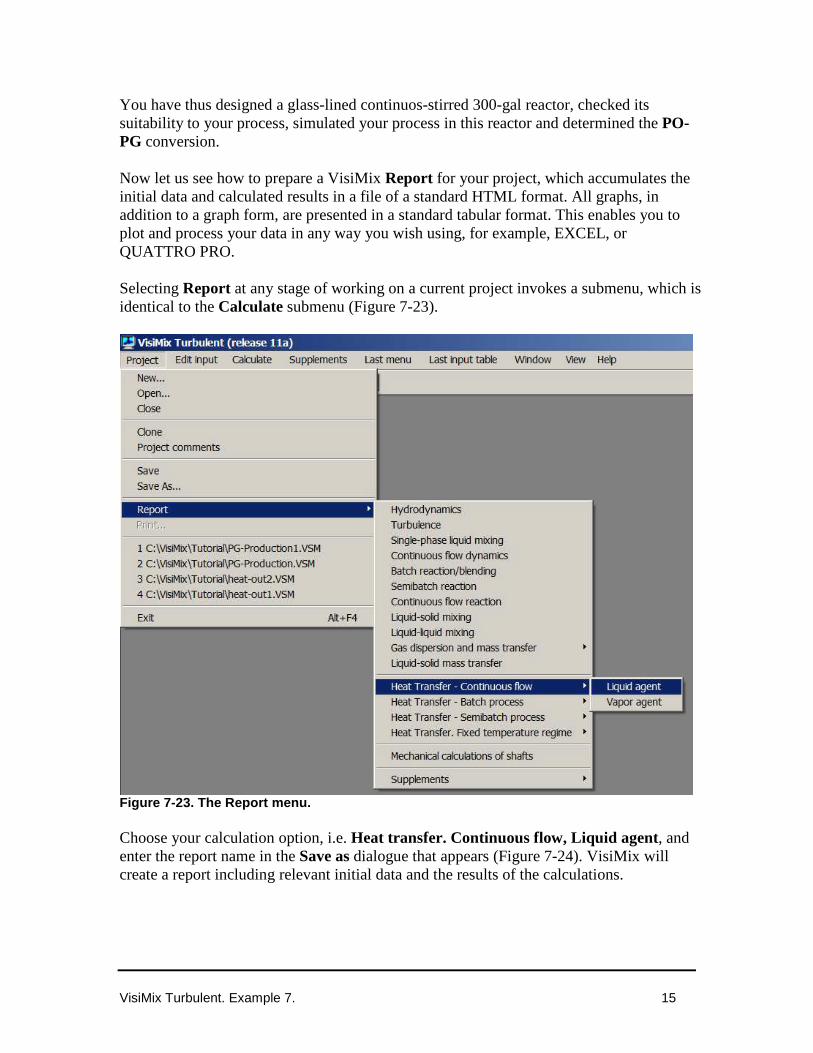
You have thus designed a glass-lined continuos-stirred 300-gal reactor, checked its suitability to your process, simulated your process in this reactor and determined the PO-PG conversion. Now let us see how to prepare a VisiMix Report for your project, which accumulates the initial data and calculated results in a file of a standard HTML format. All graphs, in addition to a graph form, are presented in a standard tabular format. This enables you to plot and process your data in any way you wish using, for example, EXCEL, or QUATTRO PRO. Selecting Report at any stage of working on a current project invokes a submenu, which is identical to the Calculate submenu (Figure 7-23).
Figure 7-23. The Report menu. Choose your calculation option, i.e. Heat transfer. Continuous flow, Liquid agent, and enter the report name in the Save as dialogue that appears (Figure 7-24). VisiMix will create a report including relevant initial data and the results of the calculations.

VisiMix Turbulent. Example 7. 16
Figure 7-24. Entering a name for the Report. On completing the report, VisiMix issues a message (Figure 7-25).
Figure 7-25. Message on the completion of the Report. Click OK. Your report is formed as a file with a .htm extension, and you may open, edit and print this file from Microsoft Internet Explorer. Some of the results for this example as they appear in the Report are shown below.

VisiMix Turbulent. Example 7. 17
THE RESULTS