Embed Size (px)
Citation preview
1
Virtual Input Glove Final Project Report December 8, 2017
E155
Spencer Michaels and Willis Sanchez-Dupont Abstract:
This project prototypes a gesture-driven input system for the Raspberry Pi that transforms
a glove into a virtualized mouse and partial keyboard. The user can (in a way reminiscent of the
Trackpoint on Lenovo laptops) control the mouse pointer with the angle of his hand, click and/or
drag by tapping or holding his fingers to his thumb, and trigger pre-configured hotkeys with up
to six directional swipe gestures. This is accomplished via three main hardware components,
namely an accelerometer, an FPGA implementing an IIR filter, and a Raspberry Pi,
communicating over SPI with the latter acting as a master to the former two. The accelerometer,
mounted on the glove, provides motion data, the FPGA filters the raw output to reduce noise,
and the Pi analyzes the filtered data to detect gestures. Finally, a driver on the Pi uses the Linux
kernel’s uinput module to produce virtual clicks and keystrokes.

2
Introduction Motivation and overview
Recent developments in technology such as virtual reality have given rise to input
devices beyond the traditional keyboard-and-mouse configuration, such as those that use the
hands or limbs for control, or even treadmills that allow the player to “walk” around an
environment. These kinds of devices can increase users’ immersion by mapping their physical
actions to identical or similar actions in the virtual world, for instance, clicking and dragging a
file like one would grab and move a real object. In order to be compatible with software that is
not designed with virtual reality in mind, such hardware typically emulates a keyboard and/or
mouse, transforming complex physical movements into keystrokes or mouse movements that
perform the equivalent action. This is especially true for hardware intended to interface with
desktop PCs, which typically do not have specialized VR interfaces as a game console might.
We chose to produce a (much simplified) physical-gesture input device of the latter type.
Namely, a glove that permits using natural hand motions to control the mouse and a limited
number of keyboard inputs on a Raspberry Pi. The user can control the device in three ways.
Firstly, the hand can be tilted at various angles to move the mouse cursor, motioning as if
manipulating a joystick, with the rate of motion proportional to the angle. (Users of the
Trackpoint input device on Lenovo laptops will also find this functionality familiar.) Secondly,
the index and middle fingers can be touched to the thumb to produce left- and right-clicks,
allowing both short taps and drag-and-drop. Thirdly, the user can swipe in one of six directions
(up, down, forward, back, left, and right) to trigger preconfigured hotkey presses, allowing for
actions like browser, desktop, and file manager navigation.
3
Implementation overview
The full system is implemented using three major hardware components: an
accelerometer, an FPGA, and a Raspberry Pi — the latter of which serves as an SPI master to the
former two, as well as running the operating system receiving the virtual inputs that are the end
product of our “device.” A few simple wires and pulldown resistors are used handle the finger
taps, and the instantaneous hand angle can be accurately translated to mouse movement using
only raw accelerometer data. Gesture recognition, however, requires more complex pre- and
post-processing of the data. This gives rise to the following partition scheme for our system.
The accelerometer, mounted on the back of the glove, sends its readings to the Pi over
SPI, which immediately forwards each one in turn to the FPGA over a second SPI channel. The
FPGA, for its part, implements an IIR filter through which the data is passed, smoothing out the
relatively noisy accelerometer readings. The results are passed back to the PI, which then
analyses them over long periods of time (on the order of seconds or fractions of seconds) to
identify gestures in the smoothed data. The Pi driver, which registers a virtual input via the Linux
kernel’s uinput module, emits virtual keyboard and mouse events in response to the gestures.
New Hardware
Our system introduces only a single piece of new hardware: the ST Microelectronics LIS3DH
accelerometer, mounted on a SparkFun Triple Axis Accelerometer LIS3DH Breakout board
(equivalent boards are also available from various other sellers, e.g. Adafruit). The LIS3DH has 12
1 SparkFun [3]
4
a 16-bit data output, a low-power mode with consumption potentially as low as 2µA, two
programmable interrupts, and an embedded temperature sensor; it can dynamically scale its
outputs to to 2g, 4g, 8g, and 16g scales, and it has both I2C and SPI communication. Our 3
implementation uses only a very small subset of these features — just the core accelerometer
functionality — and we opted to use SPI for communication with the Pi, as we already had
experience with (and code for) it. Our explanation below will thus only cover these features.
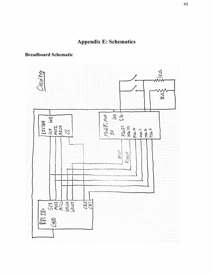
Wiring up the board
The process of wiring the LIS3DH to the Pi for SPI communication is similar to that of
any other SPI peripheral, with the Pi acting as the SPI master. SCL, SDI (“software data input”),
and SDO (“software data output”) on the accelerometer board should be wired to SCLK, MOSI,
and MISO on the Pi. The board’s pin should typically be connected to the Pi’s CE0 pin, CS
although if another SPI slave is already in use with the Pi, CE1 may also be used. The GND pins
of both devices should be connected. See the breadboard-level schematic below in appendix F.
Configuration
The LIS3DH has seven one-byte control registers, whose combined functionality far 4
exceeds what we required in our project. However, even for basic accelerometer use, some
configuration is still necessary in order to get the device up and running. (Note that in this
section, we will cover the settings required for proper device configuration, but the actual
method of writing the values to the registers will be explained in the next section.)
2 Adafruit [4] 3 ST Microelectronics[1], p. 1/54. 4 ST Microelectronics[1] p. 31/54.
5
At minimum, to initialize the device, the user must take the it out of power-down mode
by writing a four-bit number, with value between 0x1 and 0x9, into the upper half of
CTRL_REG1, i.e. the ODR register. The exact value written will determine the output data rate, 5
which may also differ depending on whether the device is in low-power, normal, or
high-resolution mode (meaning 8-, 10- or 12-bit data resolution, see below). We used a value of
0x7, producing a 400 Hz data rate in all modes; see the LIS3DH datasheet for a full table of
options. The lower half of CTRL_REG1 can be used to disable individual axes or enable
low-power mode, although the default value of 0x7 (low-power mode off, all axes enabled) is
generally preferable.
The above is all that is for accelerometer operation, but we also also modified
CTRL_REG4, enabling the BDU (block data update) and HR (high resolution) flags with an
overall register value of 0x88. The HR flag enables 12-bit resolution for accelerometer readings 6
— such that three axes’ worth of accelerometer data must be read out of three pairs of one-byte
registers for each axis — while the BDU flag blocks all updates to both bytes in a pair from the
time that reading is initiated on either byte until both the MSB and LSB have been read. This 7
prevents reading nonsensical half-updated values from the two-part registers in cases where
reading is slow or not explicitly synchronized.
SPI communication
The LIS3DH has both single- and multiple- byte read modes; both are relatively simple to
use. The master should send an eight-bit value over SPI: one (read-write) bit, one W R SM
5 ST Microelectronics [1], p. 35/51 6 ST Microelectronics [1], p. 37/51 7 ST Microelectronics [2], p. 16/59

6
(multiple-single) bit, and a six-bit register address. The first bit is self-explanatory. The second
bit, if 1, will cause the register address to auto-increment after each read or write, allowing
multiple reads/writes without respecifying the address; otherwise only one byte will be read.
After the one-byte preamble, the master should pulse the clock 8 times per byte it needs to
receive while holding MOSI low. A full table of the LIS3DH’s registers may be found in the
datasheet; immediately relevant to our purpose are the six registers from OUT_X_L to
OUT_Z_H, which contain the three low/high byte pairs of accelerometer readings, and
STATUS_REG, whose fourth bit (ZYXDA, or “ZYX data available”) indicates that new data is
available for all axes. 8
Our implementation used a single-byte read to check STATUS_REG for the ZYXDA bit,
and upon reading a 1, initiated a multi-byte read starting at OUT_X_L, reading for six bytes to
get 12-byte accelerometer values for all three axes. Note that in this case the order of the bytes in
the buffer will be big-endian (i.e. MSB first/lowest), so when segmenting into 16-bit integers on
the little-endian Pi, it is necessary to swap the byte order of each pair.
FPGA Design
Filter Design and Software Testing
The role of the FPGA in this design was to filter the raw accelerometer data. The
objective was to improve our data in two ways: (1) smooth out angular position data, and (2)
decrease the sensitivity of the accelerometer to gestures. The first case was necessary because the
accelerometer noise was significant enough that the mouse could wobble even when the user was
8 ST Microelectronics [1], p. 39/51.

7
not moving their hand. This would then preclude precise mouse movement. The second reason
why filtering was important was because even small (but relatively quick) movements of the
hand would sometimes trigger gesture-level accelerations, and potentially trigger the recognition
routine. Thus, by applying a filter, these acceleration spikes would be damped, leaving only the
significant peaks that were truly gestures.
In order to accomplish this filtering goal, an IIR filter design was chosen after testing in
MATLAB. We first experimented in MATLAB with the FFT of the accelerometer data for
various gestures. We subsequently determined that a low-pass filter with a corner frequency of
approximately 3Hz would work best, as all of the data that we wanted to keep was extremely low
frequency. There were two straightforward ways to do this: FIR filtering and IIR filtering. Using
a moving average (FIR) filter with a window size (order) of 50, we were able to obtain slightly
less filtering than a Butterworth filter (IIR) of order 3. This was a huge reduction in the number
of coefficients needed to perform filtering and thus justified why IIR filtering was a good choice
(especially considering that the coefficients would be hardcoded into SystemVerilog). We also
made comparisons between Butterworth, Chebyshev, and elliptic filters, but Butterworth was the
only type of design that we truly understood (despite the Chebyshev Type 1 providing the best
gain dropoff), so we stuck with that. Additionally, after looking Butterworth filters of varying
degree, a third-order filter was chosen because it required few coefficients while still maintaining
satisfactory damping in the stopband region.
After selecting the desired filter, we set out in Python to verify the effectiveness of this
filter by actually implementing the difference equation (see appendices). While we were able to
match identically the performance of the moving average filter, the Butterworth filter did not

8
work. To ensure that this wasn’t a code error, we also ran the filter using the Python SciPy
package, which includes a filter function with transfer function coefficients as inputs. The
difference between the SciPy filter and our filter was on the order of 10^-9 (on both basic test
cases and the full accelerometer data). Despite the Python filters not working, the MATLAB
filter function did in fact work, which thus far remains a mystery.
Hardware Filtering
Although the software filters did not work, we still attempted to implement in hardware
the difference equation describing our IIR filter. See appendix F for a schematic. At a high level,
the design is a direct implementation of the general form of IIR filters: take a linear combination
of weights with historical inputs, and subtract a linear combination of separate weights with
historical outputs. However, the design has an additional important feature - instead of
performing all the computations in parallel (which would be fast, but consume more logic
elements), our multiplication and addition are time-multiplexed. In order to complete this task, a
multiplexer is used to select corresponding weights and inputs/outputs (synchronously with the
filter clock) while a running-sum register is used to accumulate numbers until the computations
are complete. Once this process is complete, the new value is shifted to the output (and into the
output value shift register) and the process begins anew.
Although the IIR filter is the critical feature used on our FPGA, we also needed to
implement an SPI interface to transfer signals between the Raspberry Pi and the filter. This
design consisted of (1) a shift register to hold the input X, Y, and Z values, (2) three filters to
process each axis of data, and (3) a shift register to hold the output X, Y, and Z values. To

9
operate the filter, 6 bytes (each axis has a LO and HI register, together representing 12 bits of
ADC data per axis) are sent over SPI to the input shift register. A GPIO pin (whose signal we
call the ‘filter clock’) is then pulsed N times, where N is the filter order, and then the output
register sends 6 bytes of data to the Raspberry Pi. The filter clock is necessary because it governs
the time-multiplexing of the difference equation.
Software Design
Our Pi-based virtual input driver, written in C, has three primary tasks: to coordinate the
FPGA and accelerometer SPI slaves, to produce virtual mouse and keystrokes, and to identify
gestures by analyzing acceleration data. It should be noted that the two peripherals’ datasheets
and the Linux kernel documentation respectively provide ample information on SPI
communication and the generation virtual input events. As such, we will touch only briefly on
these two, and instead focus on our custom gesture recognition algorithm.
The overwhelming majority of the SPI-related code was provided by Prof. Harris’s
EasyPIO library, which covers a great deal of common GPIO functionality for the Raspberry Pi,
including alternate pin modes such as SPI. We simply needed to call spiInit() to initialize the 9
SPI interface at a rate of 500 kHz (which Adafruit uses for the LIS3DH in their own code ), and 10
then call spiSendReceive() to transmit data. To facilitate communication with the accelerometer
specifically, we wrote small wrappers around the latter function that directly take LIS3DH
register addresses and manage multi-byte reads/writes automatically. (See Accelerometer.h.)
9 Lichtman, Vasquez & Harris [7] 10 Adafruit [6]

10
Virtual keyboard/mouse input is generated via the Linux Kernel’s uinput module, which
allows userspace applications to register their own virtual input devices. They can then instruct 11
the kernel to listen for particular input events — relative mouse movement, keypresses, and so
on — and emit input events by writing them to the /dev/uinput virtual device. The resulting
events will be interpreted by the OS as if they came from a physical mouse or keyboard. Based
on the example code in the Linux kernel documentation, we wrote wrapper functions around
uinput’s low-level functionality to permit atomic keypresses and mouse movements.
Finger taps are treated as binary values and mapped directly to uinput’s “mouse button
up/down” state. Similarly, the angle of the hand is mapped onto mouse acceleration: the X and Y
angle values (which may positive or negative) are added into two accumulators at each tick, and
the mouse pointer is moved when either value exceeds a threshold, consuming that amount from
the accumulator. This produces smooth time-stepped cursor movement even at high speeds,
moving repeatedly by small amounts rather than instantly jumping by a large distance.
Gesture recognition is based on a two-level analysis of the acceleration data over long
periods of time (i.e. seconds or fractions of seconds). When the driver starts, it collects 10,000
samples and averages them to determine the baseline acceleration values of the user’s hand at
rest. Then — for each axis independently — it waits for an acceleration value whose magnitude
is at least some “noise threshold” above the baseline, indicating a strong, sudden movement. At
this point, it starts a timer, which only stops when the acceleration on that axis returns to within
the noise threshold of the baseline. If the time is within a set threshold, it records a movement,
which denotes a single motion in one direction. This constitutes the first level of analysis.
11 The Linux Kernel [5]

11
At the second level, pairs of movements are analyzed to recognize swipes. A pair of
movements is considered a swipe if (a) the first and second movement are in opposite directions
and (b) the movements occur within a short time window (with both a min and max). Thus, the
second stage is conceptually similar to the first, stopping and starting a timer based on whether a
condition is satisfied. The only major difference, in effect, is that it treats abstract movement
values as the basic unit of measurement instead of raw acceleration values. All axes are analyzed
independently, and all gestures detected at a given tick are placed into a linked list — in practice,
however, the thresholds prevent multiple gestures from being recognized at the same time.
Results
We were able to produce a prototype of our virtual input glove that works appreciably
well. The user can click and drag objects on screen by pinching them and moving his hand, and
can navigate the browser with swipe gestures (albeit somewhat clumsily, as the gesture
recognition is obviously rather primitive). However, because of what appeared to be timing
issues, we ultimately had to do all this without involving the FPGA, instead compensating for
noise in software. While obviously not ideal, this gave reasonably accurate gesture recognition.
FPGA development was beset with several setbacks throughout the project. We originally
intended to implement a neural network in hardware for gesture recognition, but soon realized
that we had underestimated the complexity of doing so. We decided instead to use an IIR filter,
smoothing out noise in hardware and performing gesture recognition in software. We
implemented the IIR filter completely, and were able to produce mostly correct waveforms for
the filter itself in ModelSim (see appendix G), but integrating it with the SPI interface produced

12
a variety of issues — likely timing-related, given the nature of SPI — that in combination with
time constraints prevented us from getting sensible values out of the filter on the FPGA.
Interestingly, when tested separately, the FIR and IIR components of the filter experienced the
same problem - the first several values were incorrect, but after the initial hiccup, they performed
exactly as expected. Additionally, examining the waveforms produced in ModelSim shows that
the some of the internal signals of the filter were switching (or failing to switch) at the wrong
times, which must be the source of the problem. This is part of the reason why we suspect that
timing was the underlying issue, because if we were ultimately producing the right pattern after a
number of clock cycles, it makes sense that the procedures performed by the hardware are
correct, whereas the timing causes the first few incorrect values to propagate indefinitely. It goes
without saying that the most difficult part of this project by far was the hardware programming.
To allow our gesture recognition to function without filtering, we instead used several
thresholding techniques in software, only counting accelerometer values that stayed above a
threshold for an extended period of time. This, in fact, distinguished signal from noise well
enough to make the gesture recognition quite accurate, at least by prototype standards. Indeed,
we suspect that, had we been able to integrate the FPGA into the design and instead used the
FIR-filtered accelerometer values, the gain in accuracy may have been effectively negligible.

13
References
[1] ST Microelectronics, MEMS digital output motion sensor: ultra-low-power
high-performance 3-axis "nano" accelerometer.
http://www.st.com/content/ccc/resource/technical/document/datasheet/3c/ae
/50/85/d6/b1/46/fe/CD00274221.pdf/files/CD00274221.pdf/jcr:content/transl
ations/en.CD00274221.pdf.
[2] ST Microelectronics, AN3308 - Application note - LIS3DH: MEMS digital output motion
sensor ultra-low-power high-performance 3-axis “nano” accelerometer.
http://www.st.com/content/ccc/resource/technical/document/application_not
e/77/ed/e7/e1/28/5a/45/d6/CD00290365.pdf/files/CD00290365.pdf/jcr:content
/translations/en.CD00290365.pdf
[3] SparkFun, SparkFun Triple Axis Accelerometer Breakout - LIS3DH.
https://www.sparkfun.com/products/13963
[4] Adafruit, ADAFRUIT LIS3DH TRIPLE-AXIS ACCELEROMETER (+-2G/4G/8G/16G).
https://www.adafruit.com/product/2809
[5] The Linux Kernel, 1.7. Uinput module.
https://www.kernel.org/doc/html/v4.12/input/uinput.html
[6] Adafruit, ADAFRUIT_LIS3DH. https://github.com/adafruit/Adafruit_LIS3DH
[7] SciPy v1.0.0 Reference Guide. Signal Processing (scipy.signal).
https://docs.scipy.org/doc/scipy/reference/signal.html
[8] Sarah Lichtman, Joshua Vasquez & Davis Harris, EasyPIO.h.
http://pages.hmc.edu/harris/class/e155/EasyPIO.h

14
Parts List
Part Source Vendor Part # Price
SparkFun Triple Axis Accelerometer Breakout - LIS3DH
Engineering stockroom
SEN-13963 $4.95
Appendix A: C Code Accelerometer.h #ifndef ACCELEROMETER_H #define ACCELEROMETER_H
#include "EasyPIO.h"
#define CTRL_REG1 0x20 #define CTRL_REG4 0x23 #define WHO_AM_I 0x0F #define OUT_X_L 0x28 #define OUT_X_H 0x29 #define OUT_Y_L 0x2A #define OUT_Y_H 0x2B #define OUT_Z_L 0x2C #define OUT_Z_H 0x2D #define STATUS_REG_AUX 0x07 #define STATUS_3ADA 0x08 #define OPT_READ 0x80 #define OPT_WRITE 0x3F #define OPT_MULTIPLE 0x40
// Write an 8-bit `value` to the register with 6-bit address `reg` void spiWrite(unsigned char reg, unsigned char value) { spiSendReceive16(reg << 8 | value, 0); }
// Read an 8-bit value from the register with 6-bit address `reg` unsigned char spiRead(unsigned char reg) { return spiSendReceive16(reg << 8 | (1 << 15), 0); }
// Configure the accelerometer void accelInit() { spiWrite(CTRL_REG1, 0x77); // highest conversion rate, all axes on

15
spiWrite(CTRL_REG4, 0x88); // block update, high resolution
while (spiRead(WHO_AM_I) != 0x33); // Wait until accel is set up }
// Clear the settings set in accelInit() void accelDeinit() { spiWrite(CTRL_REG1, 0x00); spiWrite(CTRL_REG4, 0x00); }
// Wait for new accel readings to be available for all three axes void waitFor3AxisData() { unsigned char buf; do { buf = spiRead(STATUS_REG_AUX); } while (!(buf & STATUS_3ADA)); }
// Write the bytes of buffer `buf` with size `bytes` to register `reg` void spiWriteMulti(unsigned char reg, unsigned char* buf, int bytes) { SPI0CSbits.TA = 1; spiSendReceive((reg & OPT_WRITE) | OPT_MULTIPLE, 0); for (int i = 0; i < bytes; ++i) { spiSendReceive(buf[i], 0); } SPI0CSbits.TA = 0; }
// Read `bytes` number of bytes from register `reg` into buffer `buf` void spiReadMulti(unsigned char reg, unsigned char* buf, int bytes) { SPI0CSbits.TA = 1; spiSendReceive(reg | OPT_READ | OPT_MULTIPLE, 0); for (int i = 0; i < bytes; ++i) { buf[i] = spiSendReceive(0x00, 0); } SPI0CSbits.TA = 0; }
// Read raw accelerometer values void accelReadRaw(short* x, short* y, short* z) { waitFor3AxisData();
unsigned char buf[6]; spiReadMulti(OUT_X_L, (unsigned char*) &buf, 6);
*x = (short)(((short) buf[0]) | (((unsigned short) buf[1]) << 8)); *y = (short)(((short) buf[2]) | (((unsigned short) buf[3]) << 8)); *z = (short)(((short) buf[4]) | (((unsigned short) buf[5]) << 8)); }
// Convert raw accelerometer values into factors of g void accelConvert(short xo, short yo, short zo, float* x, float* y, float* z) { *x = (float)xo / 16380; *y = (float)yo / 16380; *z = (float)zo / 16380; }
// Read g-factor accel values from the accelerometer void accelRead(float* x, float* y, float* z) {

16
short xs, ys, zs;
accelReadRaw(&xs, &ys, &zs); accelConvert(xs, ys, zs, x, y, z); }
#endif
Bindings.h #ifndef BINDINGS_H #define BINDINGS_H
#include "GestureRec.h" #include "UInput.h"
struct keypress bindings[6];
// Bind a key code with modifier state to the given gesture ID void bindGesture(int gesture, short keycode, char ctrl, char alt, char shift, char meta) { struct keypress* b = &bindings[gesture]; b->keycode = keycode; b->ctrl = ctrl; b->alt = alt; b->shift = shift; b->meta = meta; }
// Bind virtual key presses to all gestures // Edit this table to change bindings! void bindingsInit() { // Gesture | Key | Ctrl | Alt | Shift | Meta | Hand dir // Browser history nagivation bindGesture(GEST_SWIPE_X_POS, KEY_LEFT, 0, 1, 0, 0); // back bindGesture(GEST_SWIPE_X_NEG, KEY_RIGHT, 0, 1, 0, 0); // forward // Browser tab navigation bindGesture(GEST_SWIPE_Y_POS, KEY_PAGEDOWN, 0, 0, 0, 0); // down bindGesture(GEST_SWIPE_Y_NEG, KEY_PAGEUP, 0, 0, 0, 0); // up // Page up/down bindGesture(GEST_SWIPE_Z_POS, KEY_TAB, 1, 0, 0, 0); // right bindGesture(GEST_SWIPE_Z_NEG, KEY_TAB, 1, 0, 1, 0); // left }
// Get the virtual keypress associated with the given gesture ID, if any struct keypress* getBindingForGesture(int gesture) { if (gesture < 0 || gesture >= GEST_MAX) { return NULL; }
return &bindings[gesture]; }
#endif
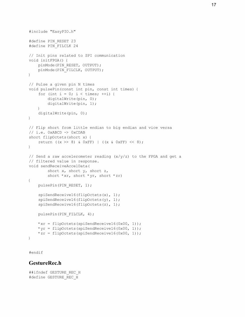
FPGA_SPI.h #ifndef FPGA_SPI_H #define FPGA_SPI_H
17
#include "EasyPIO.h"
#define PIN_RESET 23 #define PIN_FILCLK 24
// Init pins related to SPI communication void initFPGA() { pinMode(PIN_RESET, OUTPUT); pinMode(PIN_FILCLK, OUTPUT); }
// Pulse a given pin N times void pulsePin(const int pin, const int times) { for (int i = 0; i < times; ++i) { digitalWrite(pin, 0); digitalWrite(pin, 1); } digitalWrite(pin, 0); }
// Flip short from little endian to big endian and vice versa // i.e. 0xABCD -> 0xCDAB short flipOctets(short x) { return ((x >> 8) & 0xFF) | ((x & 0xFF) << 8); }
// Send a raw accelerometer reading (x/y/z) to the FPGA and get a // filtered value in response. void sendReceiveAccelData( short x, short y, short z, short *xr, short *yr, short *zr) {
pulsePin(PIN_RESET, 1);
spiSendReceive16(flipOctets(x), 1); spiSendReceive16(flipOctets(y), 1); spiSendReceive16(flipOctets(z), 1);
pulsePin(PIN_FILCLK, 4);
*xr = flipOctets(spiSendReceive16(0x00, 1)); *yr = flipOctets(spiSendReceive16(0x00, 1)); *zr = flipOctets(spiSendReceive16(0x00, 1)); }
#endif
GestureRec.h ##ifndef GESTURE_REC_H #define GESTURE_REC_H

18
#include "Sampler.h"
#define ACCEL_NOISE_THRESHOLD 5000 #define MOVE_MIN_TICKS 700 #define MOVE_MAX_TICKS 10000 #define SWIPE_MIN_TICKS 700 #define SWIPE_MAX_TICKS 10000
#define GESTURE_HAPPENING_X 1 #define GESTURE_HAPPENING_Y (1 << 1) #define GESTURE_HAPPENING_Z (1 << 2)
// Utility function, returns 1/0/-1 for pos/zero/neg x respectively. int sign(int x) { return (x > 0) - (x < 0); }
// Swipe gestures for up/down on X/Y/Z axes enum gestures { GEST_SWIPE_X_POS = 0, GEST_SWIPE_X_NEG, GEST_SWIPE_Y_POS, GEST_SWIPE_Y_NEG, GEST_SWIPE_Z_POS, GEST_SWIPE_Z_NEG, GEST_MAX, };
// The "default" hand position retrieved from calibration struct sample_t baselineSample;
void setBaselineSample(short x, short y, short z) { baselineSample.x = x; baselineSample.y = y; baselineSample.z = z; };
// Gestures are represented by a linked list of gesture types // See `enum gestures ̀ above struct gesture_t { int type; struct gesture_t* next; };
// Get the name of a gesture given its ID // See `enum gestures ̀ above const char* getGestureName(int gesture) { switch (gesture) { case GEST_SWIPE_X_POS: return "Swipe +X"; case GEST_SWIPE_X_NEG: return "Swipe -X"; case GEST_SWIPE_Y_POS: return "Swipe +Y";

19
case GEST_SWIPE_Y_NEG: return "Swipe -Y"; case GEST_SWIPE_Z_POS: return "Swipe +Z"; case GEST_SWIPE_Z_NEG: return "Swipe -Z"; default: return "Unknown"; } }
// Put a new gest. of `type ̀ onto the linked list `g`, making it the new head struct gesture_t* attachNewGesture(struct gesture_t* g, int type) { struct gesture_t* newGesture = (struct gesture_t*) malloc(sizeof(struct gesture_t));
newGesture->type = type; newGesture->next = g; return newGesture; }
// Recognizes swipes on a single axis, returning a linked list of new gestures struct gesture_t* recSwipesOneAxis( short* oldDir, short newM, // Old direction (normalized) + new meas. unsigned long long* swipeTicks, // Ticks since swipe began (write)
short* swipeDir, // Current swipe direction (write) struct gesture_t* gestures, // List of gestures int posG, int negG) // Pos/neg gesture IDs {
if (newM != 0) { int newDir = sign(newM); // normalize // If the cur. movement is in the opposite direction of the last one, // and it happened within the swipe rec. window, this is a gesture. if (*oldDir == -newDir && *swipeTicks >= SWIPE_MIN_TICKS && *swipeTicks <= SWIPE_MAX_TICKS) { gestures = attachNewGesture(gestures,(*oldDir > 0) ? posG: negG); *swipeDir = 0; *oldDir = 0; } else { // Otherwise, reset --- this is too long/short to be a swipe *swipeDir = newDir; *swipeTicks = 0; } } else if (*oldDir != 0) { // Otherwise, wait for current gesture to end *swipeTicks += 1; } else { *swipeTicks = 0; }
if (*swipeTicks > SWIPE_MAX_TICKS) { *swipeTicks = 0; *oldDir = 0; }
20
return gestures; }
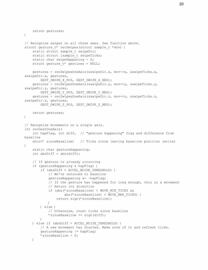
// Recognize swipes on all three axes. See function above. struct gesture_t* recSwipes(struct sample_t *mov) { static struct sample_t swipeDir; static struct lsample_t swipeTicks; static char swipeHappening = 0; struct gesture_t* gestures = NULL;
gestures = recSwipesOneAxis(&swipeDir.x, mov->x, &swipeTicks.x, &swipeDir.x, gestures, GEST_SWIPE_X_POS, GEST_SWIPE_X_NEG); gestures = recSwipesOneAxis(&swipeDir.y, mov->y, &swipeTicks.y, &swipeDir.y, gestures, GEST_SWIPE_Y_POS, GEST_SWIPE_Y_NEG); gestures = recSwipesOneAxis(&swipeDir.z, mov->z, &swipeTicks.z, &swipeDir.z, gestures, GEST_SWIPE_Z_POS, GEST_SWIPE_Z_NEG);
return gestures; }
// Recognize movements on a single axis. int recGestOneAxis( int hapFlag, int diff, // "gesture happening" flag and difference from baseline
short* sinceBaseline) // Ticks since leaving baseline position (write) {
static char gestureHappening; int absDiff = abs(diff);
// If gesture is already occurring if (gestureHappening & hapFlag) { if (absDiff < ACCEL_NOISE_THRESHOLD) { // We've returned to baseline gestureHappening &= ~hapFlag; // If the gesture has happened for long enough, this is a movement // Return its direction if (abs(*sinceBaseline) > MOVE_MIN_TICKS && abs(*sinceBaseline) < MOVE_MAX_TICKS) { return sign(*sinceBaseline); } } else { // Otherwise, count ticks since baseline *sinceBaseline += sign(diff); } } else if (absDiff > ACCEL_NOISE_THRESHOLD) { // A new movement has started. Make note of it and refresh ticks. gestureHappening |= hapFlag; *sinceBaseline = 0; }
21
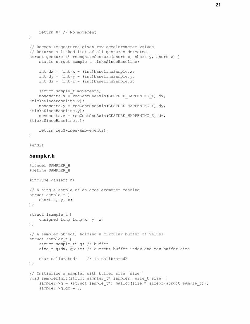
return 0; // No movement }
// Recognize gestures given raw accelerometer values // Returns a linked list of all gestures detected. struct gesture_t* recognizeGesture(short x, short y, short z) { static struct sample_t ticksSinceBaseline;
int dx = (int)x - (int)baselineSample.x; int dy = (int)y - (int)baselineSample.y; int dz = (int)z - (int)baselineSample.z;
struct sample_t movements; movements.x = recGestOneAxis(GESTURE_HAPPENING_X, dx, &ticksSinceBaseline.x);
movements.y = recGestOneAxis(GESTURE_HAPPENING_Y, dy, &ticksSinceBaseline.y);
movements.z = recGestOneAxis(GESTURE_HAPPENING_Z, dz, &ticksSinceBaseline.z);
return recSwipes(&movements); }
#endif
Sampler.h #ifndef SAMPLER_H #define SAMPLER_H
#include <assert.h>
// A single sample of an accelerometer reading struct sample_t { short x, y, z; };
struct lsample_t { unsigned long long x, y, z; };
// A sampler object, holding a circular buffer of values struct sampler_t { struct sample_t* q; // buffer size_t qIdx, qSize; // current buffer index and max buffer size
char calibrated; // is calibrated? };
// Initialize a sampler with buffer size `size` void samplerInit(struct sampler_t* sampler, size_t size) { sampler->q = (struct sample_t*) malloc(size * sizeof(struct sample_t)); sampler->qIdx = 0;
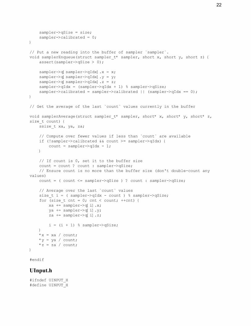
22
sampler->qSize = size; sampler->calibrated = 0; }
// Put a new reading into the buffer of sampler `sampler`. void samplerEnqueue(struct sampler_t* sampler, short x, short y, short z) { assert(sampler->qSize > 0);
sampler->q[sampler->qIdx].x = x; sampler->q[sampler->qIdx].y = y; sampler->q[sampler->qIdx].z = z; sampler->qIdx = (sampler->qIdx + 1) % sampler->qSize; sampler->calibrated = sampler->calibrated || (sampler->qIdx == 0); }
// Get the average of the last `count ̀ values currently in the buffer
void samplerAverage(struct sampler_t* sampler, short* x, short* y, short* z, size_t count) { ssize_t xa, ya, za;
// Compute over fewer values if less than `count ̀ are available if (!sampler->calibrated && count >= sampler->qIdx) { count = sampler->qIdx - 1; }
// If count is 0, set it to the buffer size count = count ? count : sampler->qSize; // Ensure count is no more than the buffer size (don't double-count any values)
count = ( count <= sampler->qSize ) ? count : sampler->qSize;
// Average over the last `count ̀ values size_t i = ( sampler->qIdx - count ) % sampler->qSize; for (size_t cnt = 0; cnt < count; ++cnt) { xa += sampler->q[i].x; ya += sampler->q[i].y; za += sampler->q[i].z;
i = (i + 1) % sampler->qSize; } *x = xa / count; *y = ya / count; *z = za / count; }
#endif
UInput.h #ifndef UINPUT_H #define UINPUT_H
23
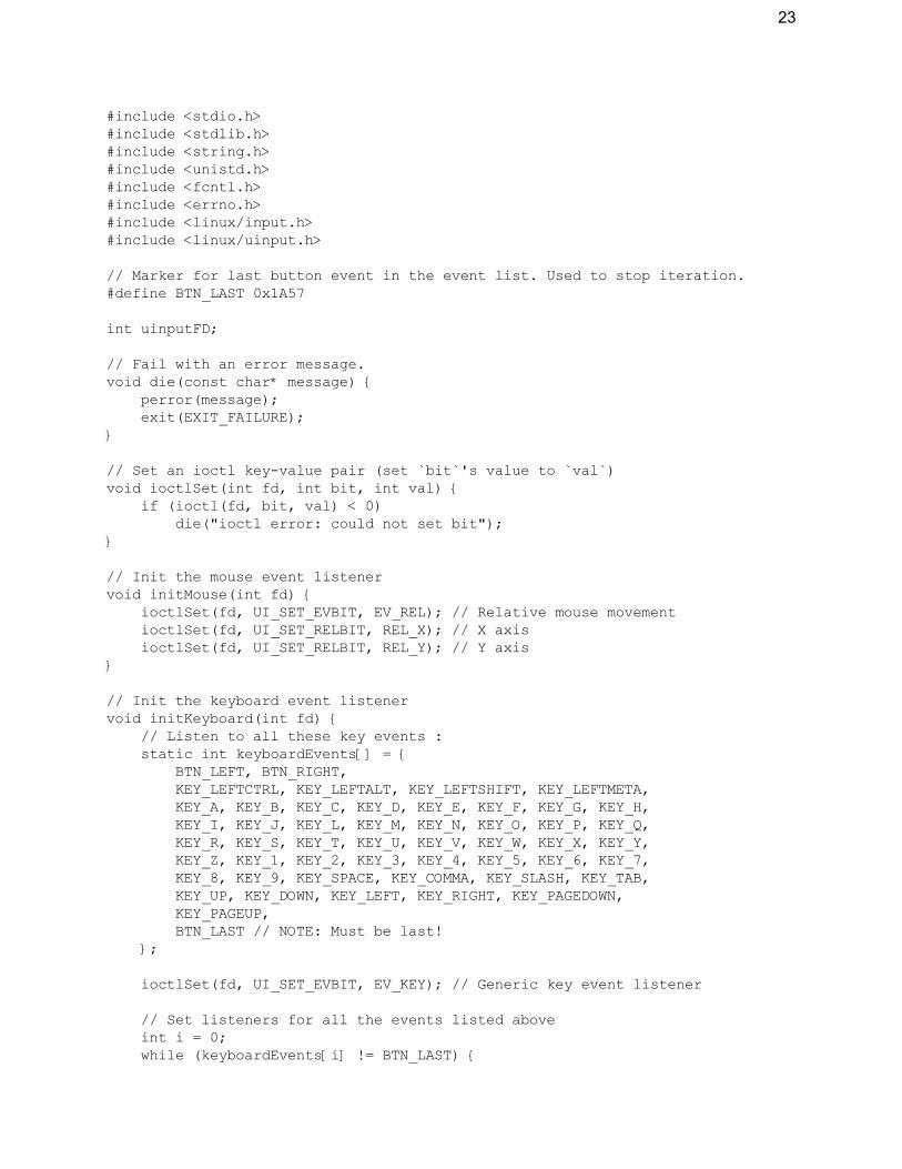
#include <stdio.h> #include <stdlib.h> #include <string.h> #include <unistd.h> #include <fcntl.h> #include <errno.h> #include <linux/input.h> #include <linux/uinput.h>
// Marker for last button event in the event list. Used to stop iteration. #define BTN_LAST 0x1A57
int uinputFD;
// Fail with an error message. void die(const char* message) { perror(message); exit(EXIT_FAILURE); }
// Set an ioctl key-value pair (set `bit`'s value to `val`) void ioctlSet(int fd, int bit, int val) { if (ioctl(fd, bit, val) < 0) die("ioctl error: could not set bit"); }
// Init the mouse event listener void initMouse(int fd) { ioctlSet(fd, UI_SET_EVBIT, EV_REL); // Relative mouse movement ioctlSet(fd, UI_SET_RELBIT, REL_X); // X axis ioctlSet(fd, UI_SET_RELBIT, REL_Y); // Y axis }
// Init the keyboard event listener void initKeyboard(int fd) { // Listen to all these key events : static int keyboardEvents[] = { BTN_LEFT, BTN_RIGHT, KEY_LEFTCTRL, KEY_LEFTALT, KEY_LEFTSHIFT, KEY_LEFTMETA, KEY_A, KEY_B, KEY_C, KEY_D, KEY_E, KEY_F, KEY_G, KEY_H, KEY_I, KEY_J, KEY_L, KEY_M, KEY_N, KEY_O, KEY_P, KEY_Q, KEY_R, KEY_S, KEY_T, KEY_U, KEY_V, KEY_W, KEY_X, KEY_Y, KEY_Z, KEY_1, KEY_2, KEY_3, KEY_4, KEY_5, KEY_6, KEY_7, KEY_8, KEY_9, KEY_SPACE, KEY_COMMA, KEY_SLASH, KEY_TAB, KEY_UP, KEY_DOWN, KEY_LEFT, KEY_RIGHT, KEY_PAGEDOWN, KEY_PAGEUP, BTN_LAST // NOTE: Must be last! };
ioctlSet(fd, UI_SET_EVBIT, EV_KEY); // Generic key event listener
// Set listeners for all the events listed above int i = 0; while (keyboardEvents[i] != BTN_LAST) {

24
ioctlSet(fd, UI_SET_KEYBIT, keyboardEvents[i]); ++i; } }
// Initialize a uinput device void initDevice(struct uinput_user_dev* uidev) { memset(uidev, 0, sizeof(struct uinput_user_dev)); snprintf(uidev->name, UINPUT_MAX_NAME_SIZE, "UInput Device"); uidev->id.bustype = BUS_USB; uidev->id.vendor = 0x1; uidev->id.product = 0x1; uidev->id.version = 1; }
// Init uinput listeners and register the given virtual device with the kernel void initUinput(int fd, struct uinput_user_dev* uidev) { ioctlSet(fd, UI_SET_EVBIT, EV_SYN);
initMouse(fd); initKeyboard(fd);
if (write(fd, uidev, sizeof(struct uinput_user_dev)) < 0) die("error: failed to write device info"); if (ioctl(fd, UI_DEV_CREATE) < 0) die("error: failed to create device"); }
// Deinitialize uinput and destroy the virtual device void deinitUinput(int fd) { if (ioctl(fd, UI_DEV_DESTROY) < 0) { die("error: failed to destroy device"); } }
// Emit a button event // From https://www.kernel.org/doc/html/latest/input/uinput.html void emit(int fd, int type, int code, int val) { struct input_event ie;
ie.type = type; ie.code = code; ie.value = val; /* timestamp values below are ignored */ ie.time.tv_sec = 0; ie.time.tv_usec = 0;
if (write(fd, &ie, sizeof(ie)) < 0) die("error: write"); }
// Move the mouse by relative coordinates (dx, dy) void moveMouse(int fd, int dx, int dy) { emit(fd, EV_REL, REL_X, dx);

25
emit(fd, EV_REL, REL_Y, dy); emit(fd, EV_SYN, 0, 0); }
// Encapsulates a key event to be emitted struct keypress { short keycode; // Key code (A, B, Space, etc.) char ctrl; // CTRL modifier char alt; // ALT modifier char shift; // SHIFT modifier char meta; // META modifier };
// Press `key` void keyDown(int fd, int key) { emit(fd, EV_KEY, key, 1); emit(fd, EV_SYN, SYN_REPORT, 0); }
// Release `key` void keyUp(int fd, int key) { emit(fd, EV_KEY, key, 0); emit(fd, EV_SYN, SYN_REPORT, 0); }
// Press and release a key along with its modifiers void hitKey(int fd, struct keypress* keypress) { if (keypress->ctrl) keyDown(fd, KEY_LEFTCTRL); if (keypress->alt) keyDown(fd, KEY_LEFTALT); if (keypress->shift) keyDown(fd, KEY_LEFTSHIFT); if (keypress->meta) keyDown(fd, KEY_LEFTMETA);
keyDown(fd, keypress->keycode);
if (keypress->ctrl) keyUp(fd, KEY_LEFTCTRL); if (keypress->alt) keyUp(fd, KEY_LEFTALT); if (keypress->shift) keyUp(fd, KEY_LEFTSHIFT); if (keypress->meta) keyUp(fd, KEY_LEFTMETA);
keyUp(fd, keypress->keycode);
emit(fd, EV_SYN, SYN_REPORT, 0); }
// Init uinput and an attendant virtual device int uinputDeviceInit() { struct uinput_user_dev uidev;
uinputFD = open("/dev/uinput", O_WRONLY | O_NONBLOCK); if (uinputFD < 0) die("error: could not open /dev/uinput.");
initDevice(&uidev); initUinput(uinputFD, &uidev);

26
}
#endif Appendix B: SystemVerilog Code
IIR_sv.sv
/*
Top-level module integrating SPI and IIR filters
- 3 filters in parallel (one for each axis of accelerometer data) - SPI shifts 6 values in (LO and HI register for each axis), then the user needs to pulse clk 4 times (4th order) - After filter pulses, user reads 6 times to get filtered data
*/
module IIR_sv(input logic filtclk, // Pulse when ready to use the filter input logic sck, // From master input logic mosi, // From master output logic miso, // To master input logic reset, // System reset input logic en, // Chip enable for spi output logic testpoint );
//************************************************
// SPI interface //************************************************
logic cen; assign cen = ~en; // Active low
logic [7:0] rawval, filteredval; // Raw and filtered values spi_slave spi(cen, sck, mosi, miso, reset, filteredval, rawval);
//************************************************
// Shift register for acceleration values //************************************************
logic [2:0] shiftcnt; always_ff @(posedge sck) begin
if(cen) begin shiftcnt <= shiftcnt + 3'b1;
end
else shiftcnt <= 0; end
logic [7:0] accelvals[5:0]; logic shiften;
27
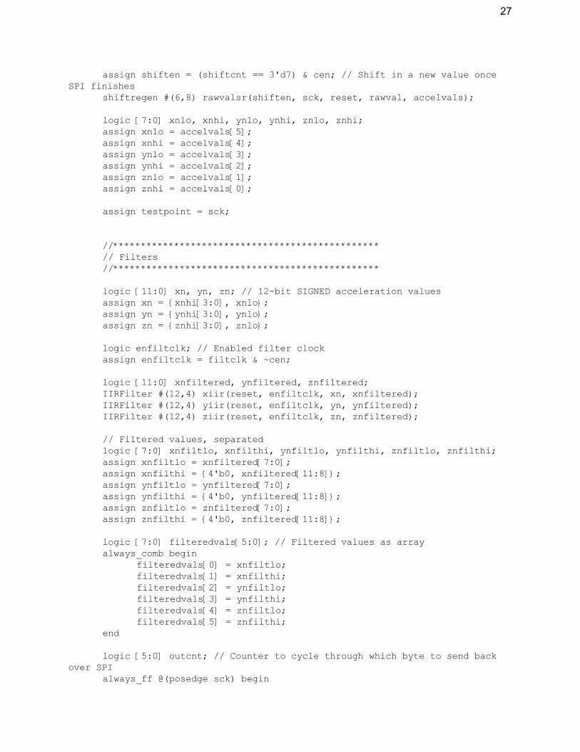
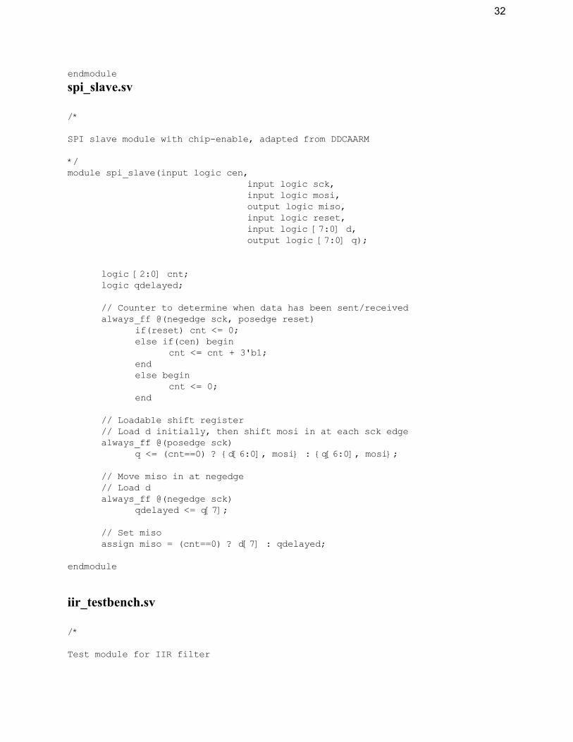
assign shiften = (shiftcnt == 3'd7) & cen; // Shift in a new value once SPI finishes
shiftregen #(6,8) rawvalsr(shiften, sck, reset, rawval, accelvals);
logic [7:0] xnlo, xnhi, ynlo, ynhi, znlo, znhi; assign xnlo = accelvals[5]; assign xnhi = accelvals[4]; assign ynlo = accelvals[3]; assign ynhi = accelvals[2]; assign znlo = accelvals[1]; assign znhi = accelvals[0];
assign testpoint = sck;
//************************************************
// Filters //************************************************
logic [11:0] xn, yn, zn; // 12-bit SIGNED acceleration values assign xn = {xnhi[3:0], xnlo}; assign yn = {ynhi[3:0], ynlo}; assign zn = {znhi[3:0], znlo};
logic enfiltclk; // Enabled filter clock assign enfiltclk = filtclk & ~cen;
logic [11:0] xnfiltered, ynfiltered, znfiltered; IIRFilter #(12,4) xiir(reset, enfiltclk, xn, xnfiltered); IIRFilter #(12,4) yiir(reset, enfiltclk, yn, ynfiltered); IIRFilter #(12,4) ziir(reset, enfiltclk, zn, znfiltered);
// Filtered values, separated logic [7:0] xnfiltlo, xnfilthi, ynfiltlo, ynfilthi, znfiltlo, znfilthi; assign xnfiltlo = xnfiltered[7:0]; assign xnfilthi = {4'b0, xnfiltered[11:8]}; assign ynfiltlo = ynfiltered[7:0]; assign ynfilthi = {4'b0, ynfiltered[11:8]}; assign znfiltlo = znfiltered[7:0]; assign znfilthi = {4'b0, znfiltered[11:8]};
logic [7:0] filteredvals[5:0]; // Filtered values as array always_comb begin
filteredvals[0] = xnfiltlo; filteredvals[1] = xnfilthi; filteredvals[2] = ynfiltlo; filteredvals[3] = ynfilthi; filteredvals[4] = znfiltlo; filteredvals[5] = znfilthi;
end
logic [5:0] outcnt; // Counter to cycle through which byte to send back over SPI
always_ff @(posedge sck) begin

28
if(reset) begin outcnt <= 5'b0;
end
else if(outcnt == 5'd5) begin // After a byte has been sent... outcnt <= 5'b0;
end
else begin outcnt <= outcnt + 5'b1;
end
end
assign filteredval = filteredvals[outcnt];
endmodule
IIR_filter.sv
/*
IIR filter module
*/
module IIRFilter #(parameter DATASIZE=16, parameter N=4)
(input logic reset, input logic clk, input logic signed [DATASIZE-1:0] xn, // x[n] output logic signed [DATASIZE-1:0] yn // y[n] );
//******************
// Data access select & regen counter // Counter to determine the mux select signals and regen //******************
logic [15:0] sel; // Select signal for the muxes and weight selection logic regen; // Enable shift registers once arithmetic is complete always_ff @(posedge clk) begin
if(reset) begin sel <= 16'b0; regen <= 1'b0;
end
else if(sel == N-1) begin sel <= 16'b0; regen <= 1'b1;
end
else begin sel <= sel + 16'b1; regen <= 1'b0;
end
end
//******************

29
// Previous input data shift register //******************
logic signed [DATASIZE-1:0] prevxvals[N-2:0]; // registered previous x values
shiftregen #(N-1,DATASIZE) srx(regen, clk, reset, xn, prevxvals);
logic signed [DATASIZE-1:0] xvals[N-1:0]; // concatentation of previous x values with current x input
assign xvals[N-1:1] = prevxvals; // combine x[n] with previous x values assign xvals[0] = xn;
//******************
// Previous output data shift register //******************
logic signed [DATASIZE-1:0] yprev; // Last output (see below) logic signed [DATASIZE-1:0] yvals[N-2:0]; // registered y values shiftregen #(N-1,DATASIZE) sry(regen, clk, reset, yprev, yvals);
//******************
// Multiplexers //******************
logic signed [DATASIZE-1:0] xi, yi; logic signed [DATASIZE-1:0] muxyin[N-1:0]; // Equalize the number of mux
inputs for xvals and yvals assign muxyin[N-1:1] = yvals; assign muxyin[0] = {DATASIZE{1'b0}}; multiplexer #(N,DATASIZE) muxx(sel, xvals, xi); multiplexer #(N,DATASIZE) muxy(sel, muxyin, yi);
//******************
// Multipliers //******************
logic signed [DATASIZE-1:0] bi, ai; // ith weight values ROMa #(N,DATASIZE) romaout(sel, ai); ROMb #(N,DATASIZE) rombout(sel, bi); logic signed [DATASIZE-1:0] mulxout, mulyout; multiplier #(DATASIZE) mulx(bi, xi, mulxout); multiplier #(DATASIZE) muly(ai, yi, mulyout);
//******************
// Adders //******************
logic signed [DATASIZE-1:0] runningx, runningy; // Running totals of x and y
logic signed [DATASIZE-1:0] xsum, ysum; // Output of the adders adder #(DATASIZE) addx(mulxout, runningx, xsum); adder #(DATASIZE) addy(mulyout, runningy, ysum);
// Feedback for adder/subtractor always_ff @(posedge clk) begin
if(reset) begin runningx <= {DATASIZE{1'b0}}; runningy <= {DATASIZE{1'b0}};
end

30
else begin runningx <= xsum; runningy <= ysum;
end
end
//******************
// Final sum junction //******************
subtractor #(DATASIZE) subxy(xsum, ysum, yprev);
// Flipflop to output y[n] // Enabled only once new value has been generated always_ff @(posedge clk) begin
if(reset) begin yn <= {DATASIZE{1'b0}};
end
else if(regen) begin yn <= yprev;
end
end
endmodule
module multiplexer #(parameter NUMINPUTS=2, WIDTH=16) (input logic [15:0] sel, // 16 bits for 32767 possible selections input logic signed [WIDTH-1:0] inputs[NUMINPUTS-1:0], output logic signed [WIDTH-1:0] out);
assign out = inputs[sel];
endmodule
module multiplier #(parameter N=16) (input logic signed [N-1:0] in1, input logic signed [N-1:0] in2, output logic signed [N-1:0] product);
assign product = in1 * in2; endmodule
module ROMb #(parameter MEMSIZE=4,DATASIZE=16) (input logic [15:0] index, output logic signed [DATASIZE-1:0] value);
logic signed [DATASIZE-1:0] data[MEMSIZE-1:0]; always_comb begin
data[0] = {DATASIZE{1'b0}} + 2'd1; data[1] = {DATASIZE{1'b0}} + 2'd1; data[2] = {DATASIZE{1'b0}} + 2'd1; data[3] = {DATASIZE{1'b0}} + 2'd1;
end
31
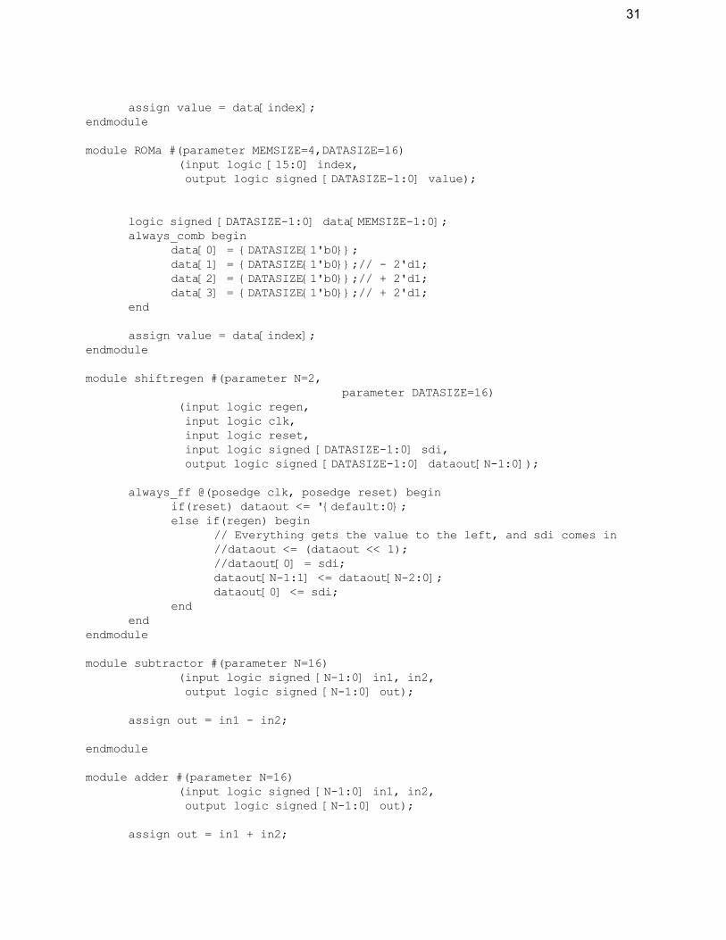
assign value = data[index]; endmodule
module ROMa #(parameter MEMSIZE=4,DATASIZE=16) (input logic [15:0] index, output logic signed [DATASIZE-1:0] value);
logic signed [DATASIZE-1:0] data[MEMSIZE-1:0]; always_comb begin
data[0] = {DATASIZE{1'b0}}; data[1] = {DATASIZE{1'b0}};// - 2'd1; data[2] = {DATASIZE{1'b0}};// + 2'd1; data[3] = {DATASIZE{1'b0}};// + 2'd1;
end
assign value = data[index]; endmodule
module shiftregen #(parameter N=2, parameter DATASIZE=16)
(input logic regen, input logic clk, input logic reset, input logic signed [DATASIZE-1:0] sdi, output logic signed [DATASIZE-1:0] dataout[N-1:0]);
always_ff @(posedge clk, posedge reset) begin if(reset) dataout <= '{default:0}; else if(regen) begin
// Everything gets the value to the left, and sdi comes in //dataout <= (dataout << 1); //dataout[0] = sdi; dataout[N-1:1] <= dataout[N-2:0]; dataout[0] <= sdi;
end
end
endmodule
module subtractor #(parameter N=16) (input logic signed [N-1:0] in1, in2, output logic signed [N-1:0] out);
assign out = in1 - in2;
endmodule
module adder #(parameter N=16) (input logic signed [N-1:0] in1, in2, output logic signed [N-1:0] out);
assign out = in1 + in2;
32
endmodule
spi_slave.sv
/*
SPI slave module with chip-enable, adapted from DDCAARM
*/
module spi_slave(input logic cen, input logic sck, input logic mosi, output logic miso, input logic reset, input logic [7:0] d, output logic [7:0] q);
logic [2:0] cnt; logic qdelayed;
// Counter to determine when data has been sent/received always_ff @(negedge sck, posedge reset)
if(reset) cnt <= 0; else if(cen) begin
cnt <= cnt + 3'b1; end
else begin cnt <= 0;
end
// Loadable shift register // Load d initially, then shift mosi in at each sck edge always_ff @(posedge sck)
q <= (cnt==0) ? {d[6:0], mosi} : {q[6:0], mosi};
// Move miso in at negedge // Load d always_ff @(negedge sck)
qdelayed <= q[7];
// Set miso assign miso = (cnt==0) ? d[7] : qdelayed;
endmodule
iir_testbench.sv
/*
Test module for IIR filter

33
*/
module iir_testbench();
logic clk; logic reset; logic [15:0] xn; assign xn = 16'd1; // 16-bit 1 as constant input logic [15:0] yn;
logic [15:0] clkcnt; initial begin
clkcnt = 16'b0; end
always_ff @(posedge clk) begin if(clkcnt == 16'b10000000) begin
$stop; // End after a while end
else begin clkcnt = clkcnt + 16'b1;
end
end
// IIR filter device under test IIRFilter #(16,3) dut_iir(reset, clk, xn, yn);
// SPI device under test logic miso; logic [7:0] datarx; // Data to be received spi_slave dut_spi(1'b1, clk, 1'b1, miso, reset, 8'b01000000, datarx);
initial begin clk = 1'b0; reset = 1'b1; #5;
clk = 1'b1; #5;
clk = 1'b0; reset = 1'b0; #5;
forever begin clk = 1'b1; #5;
clk = 1'b0; #5;
end
end
endmodule

34
Appendix C: Python Code
IIRFilter.py
"""
IIR Filter
Notes:
xn = input signal yn = output signal
a = denominator coefficients of transfer function b = numerator coefficients of transfer function
Default filter just gives the input
"""
class IIRFilter: def __init__(self, xn=[], a=[1], b=[1]): self.__xn = xn # input x[n] self.__yn = [] # output y[n] self.__a = a # format [ a1, a2, a3... aN+1 ] self.__b = b # format [ b0, b1, b2... bM+1 ]
""" Get the output signal array """ def getOutput(self): return self.__yn
""" Return the input signal array """ def getInput(self): return self.__xn;
""" Set the input signal """ def setInput(self, sig): self.__xn = sig
""" Get the transfer function coefficients
Format [a, b] """ def getCoeffs(self): return [self.__a,self.__b]
35
""" Set the transfer function coefficients
Format a, b """ def setCoeffs(self, a, b): self.__a = a self.__b = b
""" A function to compute a linear combination """ def lincomb(self,u,v): output = 0 for i in range(len(u)): output += u[i]*v[i] return output
""" Filter the input signal """ def filter(self): self.__yn = [] # Reset any previous output
# Pad x[n] and y[n] with zeroes so that we can convolve paddedx = (len(self.__b)-1)*[0] + self.__xn # len(b)-1 because x[n] still matters paddedy = (len(self.__a)-1)*[0] + self.__yn # len(a)-1 due to y[n] coefficient
# Reversed coefficient lists for the convolution aRev = self.__a[:0:-1] # Exclude coefficient of y[n] (a0) bRev = self.__b[::-1]
# Loop through x[n], summing feedback and feedforward components for i in range(len(self.__xn)): bComponent = self.lincomb(bRev, paddedx[i:i + len(bRev)]) aComponent = self.lincomb(aRev, paddedy[i:i + len(aRev)]) self.__yn.append((1.0/self.__a[0]) * (bComponent - aComponent)) paddedy.append(self.__yn[-1]) # Tack on the last output to paddedy
""" Moving average FIR """ def movingAverage(self,windowSize=50): self.__b = windowSize * [1.0/windowSize] self.__a = [1]
""" Reset filter """ def reset(self): print("Resetting filter parameters to defaults...") self.xn = []

36
self.yn = [] self.__a = [1] self.__b = [1]
iirtest.py
"""
IIR filter test script
"""
from IIRFilter import * import numpy as np from matplotlib import pyplot as plt
# Very basic test case b = [1,1,8] a = [1, 2,-1] s = [1,2,3,4,5,6,7,8,9] filt = IIRFilter() filt.setCoeffs(a,b)
filt.setInput(s)
filt.filter() # Should be [1,3,5,7...] print("Basic filter output: ",filt.getOutput())
# Collect data from file filename = 'testdata0.csv' # filename = 'lis3dh_testdata.csv'; data = open(filename,'r') lines = data.read().split('\n') splitLines = [] for i in range(1,len(lines)): splitLines.append(lines[i].split(','))
times = [] aZ = [] for i in range(len(splitLines)-1): times.append(float(splitLines[i][0])) aZ.append(float(splitLines[i][3]))
# Fs = len(times)/times[-1] # print("Fs = ",Fs)
# Initialize the filter f = IIRFilter()
# 4th order Butterworth filter with a0 = 1 # f_c = 3Hz, Fs ~= 411Hz # f_n ~= 0.0146 b = [0.000000260,0.000001042,0.000001563,0.000001042,0.000000260] a = [1,-3.8802,5.6476,-3.6545,0.8871]

37
# Set filter parameters # print("Setting input to aZ...") f.setInput(aZ)
# print("Setting coefficients to a and b...") f.setCoeffs(a,b)
# IIR filtering # print("Filtering s...") f.filter()
iirOut = f.getOutput()
f.movingAverage(50)
f.filter()
firOut = f.getOutput()
# Plotting plt.figure(1)
# Original data plt.subplot(3,1,1)
plt.plot(range(len(aZ)),aZ,'black')
plt.title('Unfiltered data'); plt.xlabel('Sample number'); plt.ylabel('Acceleration (g)');
# 50th order moving average (FIR) filter plt.subplot(3,1,2)
plt.plot(range(len(aZ)),firOut,'g')
plt.title('50th Order Moving average FIR Filter'); plt.xlabel('Sample number'); plt.ylabel('Acceleration (g)');
# 4th order Butterworth (IIR) filter plt.subplot(3,1,3)
plt.plot(range(len(aZ)),iirOut,'b')
plt.title('4th Order Butterworth IIR Filter (fc = 3Hz, Fs ~= 411Hz)'); plt.xlabel('Sample number'); plt.ylabel('Acceleration (g)');
plt.show()
# Python IIR from scipy import signal as sig pyIIR = sig.lfilter(b,a,aZ) pyFF = sig.filtfilt(b,a,aZ)
# Determine difference between homemade IIR and scipy IIR pyErrors = [] for i in range(len(pyIIR)): pyErrors.append(pyIIR[i] - iirOut[i])
38
print('max(pyErrors) = ',max(pyErrors)) print('min(pyErrors) = ',min(pyErrors))
# Compare output of this filter to MATLAB output filename = 'matlab_IIR_output.csv' with open(filename) as f: matlab_out = f.read().split('\n')
print('matlab_out[:10] = ', matlab_out[:10]) print('iirOut[:10] = ', iirOut[:10])
matlab_out = list(map(float,matlab_out[:-1])) # Convert everything to float
# Compute error errors = [] for i in range(len(matlab_out)): errors.append(matlab_out[i] - iirOut[i])
plt.figure(2)
plt.subplot(3,1,1)
plt.plot(range(len(matlab_out)),matlab_out,'b')
plt.subplot(3,1,2)
plt.plot(range(len(matlab_out)),iirOut,'r')
plt.plot(range(len(matlab_out)),pyIIR,'yellow')
# Plot difference between DIY IIR filter and scipy IIR filter plt.plot(range(len(matlab_out)),pyErrors,'black')
plt.subplot(3,1,3)
plt.plot(range(len(matlab_out)), errors, 'g') plt.show()
""" ******************************** Quick LIS3DH data plotting ********************************
# Data from LIS3DH filename = 'lis3dh_testdata.csv' data = open(filename,'r') lines = data.read().split('\n') splitLines = [] for i in range(1,len(lines)): splitLines.append(lines[i].split(', '))
zdata = [] for i in range(len(splitLines)-1): zdata.append(float(splitLines[i][2]))
filt = IIRFilter() filt.setInput(zdata)
# 50th order moving moving average filt.movingAverage()
filt.filter()
zmovingav = filt.getOutput()

39
filt.setCoeffs(a,b)
filt.filter()
iirz = filt.getOutput()
plt.figure(3)
plt.title("LIS3DH Data") # Original data plt.subplot(3,1,1)
plt.plot(range(len(zdata)), zdata,'black') plt.title('Unfiltered data'); plt.xlabel('Sample number'); plt.ylabel('Acceleration (g)');
# 50th order moving average (FIR) filter plt.subplot(3,1,2)
plt.plot(range(len(zdata)), zmovingav,'g') plt.title('50th Order Moving average FIR Filter'); plt.xlabel('Sample number'); plt.ylabel('Acceleration (g)');
# 4th order Butterworth (IIR) filter plt.subplot(3,1,3)
plt.plot(range(len(zdata)), iirz,'b') plt.title('4th Order Butterworth IIR Filter (fc = 3Hz, Fs ~= 411Hz)'); plt.xlabel('Sample number'); plt.ylabel('Acceleration (g)');
plt.show()
"""

40
Appendix D: MATLAB Code
% Willis Sanchez-duPont & Spencer Michaels % E155 project
rowoffset = 1; % Ignore column titles (strings) filename = 'sample_swipeleft1.csv'; swipeL = csvread(filename,rowoffset); % Collect swipeleft filename = 'sample_swiperight1.csv'; swipeR = csvread(filename,rowoffset); % Collect swiperight data filename = 'sample_baseline.csv'; baseline = csvread(filename,rowoffset); filename = 'testdata0.csv'; % filename = 'lis3dh_testdata.csv'; td0 = csvread(filename,rowoffset);
% Get time + z-axis data timestd = td0(:,1); timesL = swipeL(:,1); timesR = swipeR(:,1); timesB = baseline(:,1); aztd = td0(:,4); azL = swipeL(:,4); azR = swipeR(:,4); azB = baseline(:,4);
lentd = length(timestd); lenL = length(timesL); lenR = length(timesR); lenB = length(timesB);
Fstd = lentd / timestd(end); FsL = lenL / timesL(end); FsR = lenR / timesR(end); FsB = lenB / timesB(end);
freqsL = FsL * (0:lenL-1) / lenL; freqsR = FsR * (0:lenR-1) / lenR; freqsB = FsB * (0:lenB-1) / lenB;
% % Plot the raw data % figure(1) %
% subplot(2,1,1); % plot(0:length(azL)-1, azL, 'b'); % title('Raw leftswipe data') % xlabel('Time (s)'); % ylabel('az (g)'); %
% subplot(2,1,2); % plot(timesR, azR, 'g') % title('Raw rightswipe data')
41
% xlabel('Time (s)'); % ylabel('az (g)'); %
%
% % FFT of swipes % azLFFT = fft(azL); % azRFFT = fft(azR); % azBFFT = fft(azB); %
% reaZL = abs(azLFFT); % reaZR = abs(azRFFT); % reaZB = abs(azBFFT); %
% ub = 50; %
% freqsL = freqsL(1:ub); % freqsR = freqsR(1:ub); % freqsB = freqsB(1:ub); %
% reaZL = reaZL(1:ub); % reaZR = reaZR(1:ub); % reaZB = reaZB(1:ub); %
% figure(2) %
% subplot(2,2,1); % plot(freqsL, reaZL, 'b') % title('azL fft') % ylabel('Magnitude'); % xlabel('Frequency (Hz)') %
% subplot(2,2,2); % plot(freqsR, reaZR, 'g') % title('azR fft'); % ylabel('Magnitude'); % xlabel('Frequency (Hz)') %
% subplot(2,2,[3 4]) % plot(freqsB,reaZB, 'r') % title('Baseline fft'); % ylabel('Magnitude') % xlabel('Frequency (Hz)')
% ************************** % FILTER TESTING HERE % **************************
% Very basic test case to validate python implementation b = [1 1]; a = [1 -1]; testsignal = [ 1 1 1 1 1 1 1 1 1 ]; y = filter(b,a,testsignal); % Should be [ 1 3 5 7 ... ] disp('Basic filter results:')
42
disp(y)
figure(4)
% Original data subplot(3,1,1)
plot(0:length(aztd)-1,aztd,'black')
title('Unfiltered Data'); xlabel('Sample number'); ylabel('Acceleration (g)');
% 50th order moving average (FIR) filter windowSize = 50; b = (1/windowSize)*ones(1,windowSize); a = 1; y = filter(b,a,aztd); subplot(3,1,2);
plot(0:length(y)-1,y,'g');
title('50th Order Moving Average FIR Filter'); xlabel('Sample number'); ylabel('Acceleration (g)');
% 4th order Butterworth (IIR) filter fc = 3; fn = fc/(Fstd/2); [b a] = butter(3,fn) y = filter(b,a,aztd); subplot(3,1,3);
plot(0:length(y)-1,y,'b');
hold on plot(0:length(y)-1,filtfilt(b,a,aztd));
title('4th Order Butterworth IIR Filter (fc = 3Hz)'); xlabel('Sample number'); ylabel('Acceleration (g)');
% Write IIR output to check against python filter filename = 'matlab_IIR_output.csv'; csvwrite(filename,y);
43
Appendix E: Schematics
Breadboard Schematic

44
Top-Level FPGA Schematic

45
IIR Filter Schematic

46
Appendix G: ModelSim Waveforms

![phagottt 16 09 Pr Michel Dupon [Mode de compatibilité] · Microsoft PowerPoint - phagottt 16 09 Pr Michel Dupon [Mode de compatibilité] Author: cpiau Created Date: 10/25/2016](https://img.dokumen.tips/doc/110x75/5f0f80707e708231d4447a8b/phagottt-16-09-pr-michel-dupon-mode-de-compatibilitf-microsoft-powerpoint-.jpg)


![Présentation os pdiab 13 10 Q R Pr Michel Dupon [Mode de ... · Microsoft PowerPoint - Présentation os pdiab 13 10 Q R Pr Michel Dupon [Mode de compatibilité] Author: cpiau](https://img.dokumen.tips/doc/110x75/5f650936ac997665162d3a10/prfsentation-os-pdiab-13-10-q-r-pr-michel-dupon-mode-de-microsoft-powerpoint.jpg)