Embed Size (px)
Citation preview
E155 Final Project Report Duncan Crowley and Ragini Kothari Prof. D. Money Harris 12/6/2017
Subatomic Current Song Display
Abstract:
In this project, a display was designed to read out the name and artist of songs playing on the
Subatomic speakers at West Dorm, using song data scrobbled through the music recording
service known as last.fm. Since dorm residents were interested in knowing what music was
being played over their speakers, the speaker operators have recorded their music through this
service for all to see if they want to look up a recent song on the internet. We take that a step
further using a Raspberry Pi as a web scraper and an FPGA as an LED Matrix display
controller. Here, the current song’s data is scraped from the last.fm website using their API, and
converted into a font that can fit on an 8 x 8 LED matrix display. Then, that data is sent over SPI
to the FPGA, which controls the image displayed on four 8x8 LED matrices using shift registers
and transistor switches. Although the FPGA datapath does not completely function as intended,
it can load an image into RAM and then display that image using a controller to keep the loading
and display steps separate. Overall, our hope is that this acts as an easy to follow methodology
for making an LED matrix display for readable text, and for getting song information from
Last.fm, which can be useful for future students taking E155 with similar ambitions.
Introduction:
This report entails the design and implementation of displaying readable scrolling font of song
information on LED matrices. West Dorm at Harvey Mudd College has a speaker suite,
Subatomic, that plays music for all the residents to enjoy. Having a readable information board
with the most recently played song information would be a nice addition to the speaker suite and
will allow residents to stay informed about the music that is being played in the courtyard.The
music history for Subatomic speakers is hosted on the Last.fm database. In order to display the
current song information the team used the last.fm API and sent the information through SPI
communication to the FPGA. The team used 4 8x8 Red LED matrices, with transistors and shift
registers to appropriately move in the data and control the matrices to create a readable font.
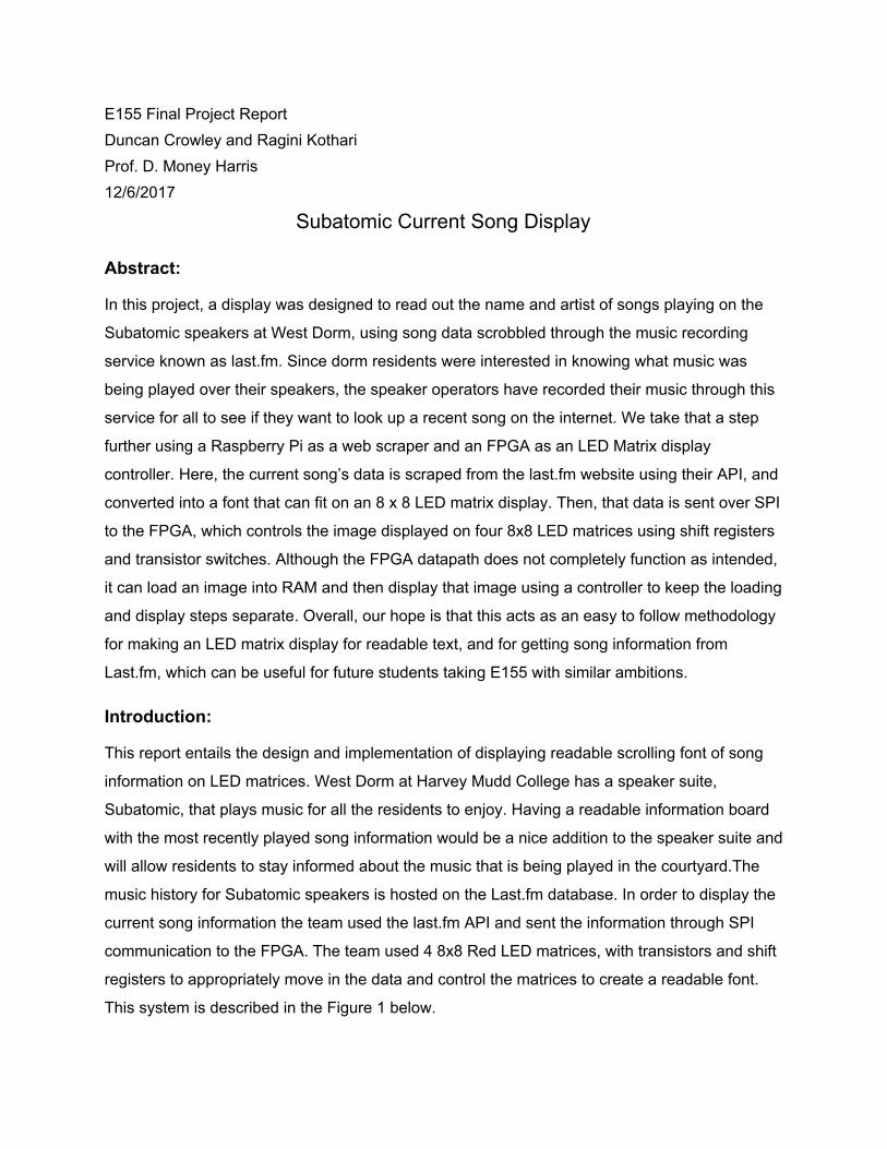
This system is described in the Figure 1 below.
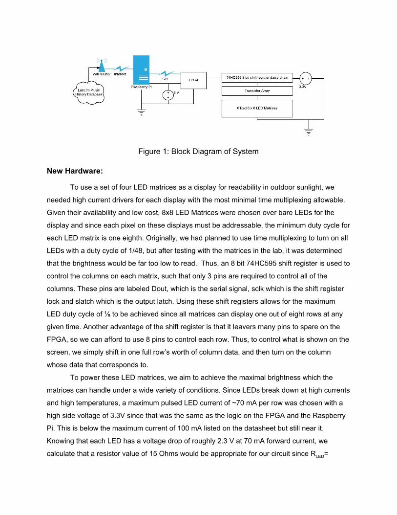
Figure 1: Block Diagram of System
New Hardware:
To use a set of four LED matrices as a display for readability in outdoor sunlight, we
needed high current drivers for each display with the most minimal time multiplexing allowable.
Given their availability and low cost, 8x8 LED Matrices were chosen over bare LEDs for the
display and since each pixel on these displays must be addressable, the minimum duty cycle for
each LED matrix is one eighth. Originally, we had planned to use time multiplexing to turn on all
LEDs with a duty cycle of 1/48, but after testing with the matrices in the lab, it was determined
that the brightness would be far too low to read. Thus, an 8 bit 74HC595 shift register is used to
control the columns on each matrix, such that only 3 pins are required to control all of the
columns. These pins are labeled Dout, which is the serial signal, sclk which is the shift register
lock and slatch which is the output latch. Using these shift registers allows for the maximum
LED duty cycle of ⅛ to be achieved since all matrices can display one out of eight rows at any
given time. Another advantage of the shift register is that it leavers many pins to spare on the
FPGA, so we can afford to use 8 pins to control each row. Thus, to control what is shown on the
screen, we simply shift in one full row’s worth of column data, and then turn on the column
whose data that corresponds to.
To power these LED matrices, we aim to achieve the maximal brightness which the
matrices can handle under a wide variety of conditions. Since LEDs break down at high currents
and high temperatures, a maximum pulsed LED current of ~70 mA per row was chosen with a
high side voltage of 3.3V since that was the same as the logic on the FPGA and the Raspberry
Pi. This is below the maximum current of 100 mA listed on the datasheet but still near it. Knowing that each LED has a voltage drop of roughly 2.3 V at 70 mA forward current, we
calculate that a resistor value of 15 Ohms would be appropriate for our circuit since RLED=
(Vsupply-VLED) / i LED. Unfortunately, the CMOS IO pins on our FPGA cannot supply such high
currents, so a high side PNP transistor is needed to source current and a low side NPN
transistor is needed to sink current. To make things easy for ourselves, we bought cheap NPN
Darlington transistor ICs which have 8 NPN sinks for a max current of 2.5 A per IC (yikes!).
Each sink on these NPN ICs can be turned on by sending a high signal to the input rail for each
given pin, so each chip has 8 inputs and 8 output sinks. On the high side, we were unable to
find as convenient of a solution as the NPN ICs, so we have chosen to simply use 48 individual
PNP transistors to source the LED current. Using the classic 2N3906 BJT PNP transistor with a
HFE = 100, we used a 3.5 kOhm resistor from the shift register to the base to give a maximum
source current of ~100 mA. This can be found using the equation: Rbase = Vsupply(1.3 x min HFE) / i MAXLED. Then, to ensure that the transistor switch is completely turned off when 3.3 volts is
applied to the base resistor, we use a pull-up resistor of 43 kOhms on the emitter that is more
than ten times the resistance of our base resistor. Knowing all of this, the circuit for the LED
matrix multiplexing is summarized below in Figure 2a and 2b.
Figure 2a: Analog Circuit Design for LED Matrix Display
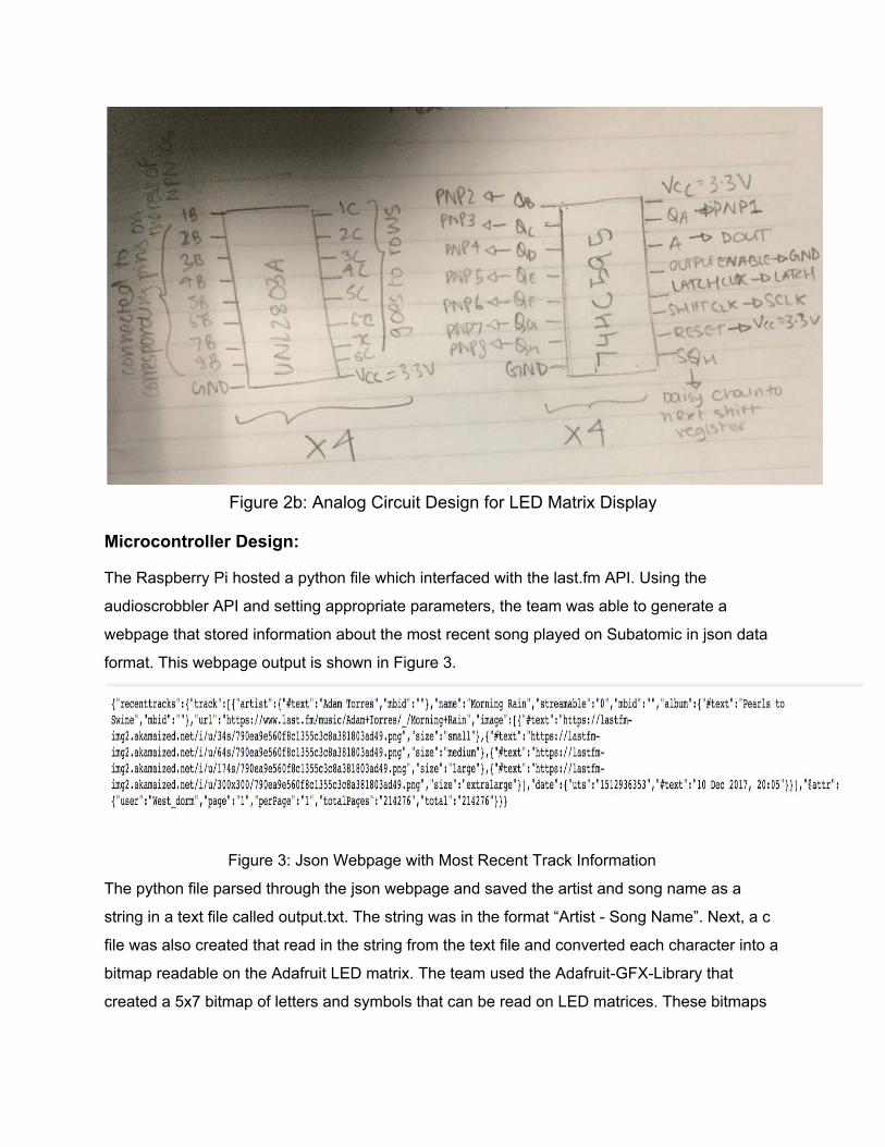
Figure 2b: Analog Circuit Design for LED Matrix Display
Microcontroller Design:
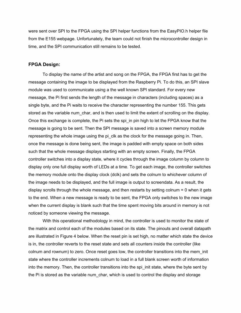
The Raspberry Pi hosted a python file which interfaced with the last.fm API. Using the
audioscrobbler API and setting appropriate parameters, the team was able to generate a
webpage that stored information about the most recent song played on Subatomic in json data
format. This webpage output is shown in Figure 3.
Figure 3: Json Webpage with Most Recent Track Information
The python file parsed through the json webpage and saved the artist and song name as a
string in a text file called output.txt. The string was in the format “Artist - Song Name”. Next, a c
file was also created that read in the string from the text file and converted each character into a
bitmap readable on the Adafruit LED matrix. The team used the Adafruit-GFX-Library that
created a 5x7 bitmap of letters and symbols that can be read on LED matrices. These bitmaps
were sent over SPI to the FPGA using the SPI helper functions from the EasyPIO.h helper file
from the E155 webpage. Unfortunately, the team could not finish the microcontroller design in
time, and the SPI communication still remains to be tested.
FPGA Design:
To display the name of the artist and song on the FPGA, the FPGA first has to get the
message containing the image to be displayed from the Raspberry Pi. To do this, an SPI slave
module was used to communicate using a the well known SPI standard. For every new
message, the Pi first sends the length of the message in characters (including spaces) as a
single byte, and the Pi waits to receive the character representing the number 155. This gets
stored as the variable num_char, and is then used to limit the extent of scrolling on the display.
Once this exchange is complete, the Pi sets the spi_in pin high to let the FPGA know that the
message is going to be sent. Then the SPI message is saved into a screen memory module
representing the whole image using the pi_clk as the clock for the message going in. Then,
once the message is done being sent, the image is padded with empty space on both sides
such that the whole message displays starting with an empty screen. Finally, the FPGA
controller switches into a display state, where it cycles through the image column by column to
display only one full display worth of LEDs at a time. To get each image, the controller switches
the memory module onto the display clock (dclk) and sets the colnum to whichever column of
the image needs to be displayed, and the full image is output to screendata. As a result, the
display scrolls through the whole message, and then restarts by setting colnum = 0 when it gets
to the end. When a new message is ready to be sent, the FPGA only switches to the new image
when the current display is blank such that the time spent moving bits around in memory is not
noticed by someone viewing the message.
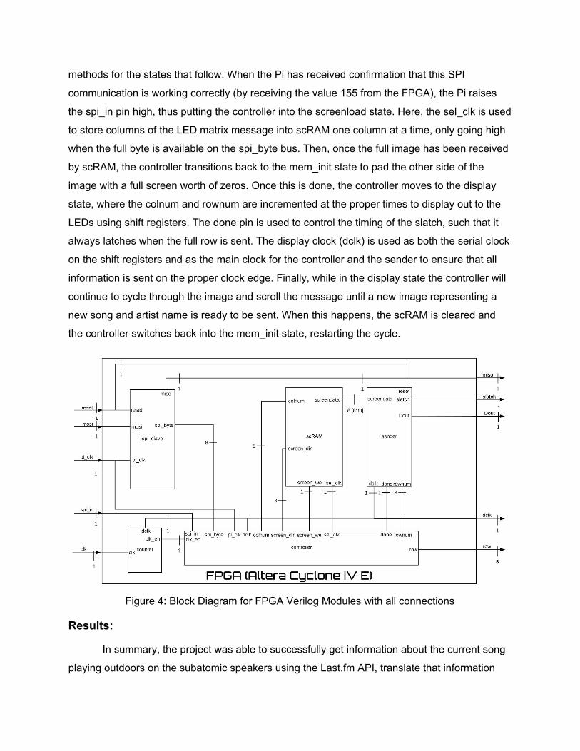
With this operational methodology in mind, the controller is used to monitor the state of
the matrix and control each of the modules based on its state. The pinouts and overall datapath
are illustrated in Figure 4 below. When the reset pin is set high, no matter which state the device
is in, the controller reverts to the reset state and sets all counters inside the controller (like
colnum and rownum) to zero. Once reset goes low, the controller transitions into the mem_init
state where the controller increments colnum to load in a full blank screen worth of information
into the memory. Then, the controller transitions into the spi_init state, where the byte sent by
the Pi is stored as the variable num_char, which is used to control the display and storage
methods for the states that follow. When the Pi has received confirmation that this SPI
communication is working correctly (by receiving the value 155 from the FPGA), the Pi raises
the spi_in pin high, thus putting the controller into the screenload state. Here, the sel_clk is used
to store columns of the LED matrix message into scRAM one column at a time, only going high
when the full byte is available on the spi_byte bus. Then, once the full image has been received
by scRAM, the controller transitions back to the mem_init state to pad the other side of the
image with a full screen worth of zeros. Once this is done, the controller moves to the display
state, where the colnum and rownum are incremented at the proper times to display out to the
LEDs using shift registers. The done pin is used to control the timing of the slatch, such that it always latches when the full row is sent. The display clock (dclk) is used as both the serial clock
on the shift registers and as the main clock for the controller and the sender to ensure that all
information is sent on the proper clock edge. Finally, while in the display state the controller will
continue to cycle through the image and scroll the message until a new image representing a
new song and artist name is ready to be sent. When this happens, the scRAM is cleared and
the controller switches back into the mem_init state, restarting the cycle.
Figure 4: Block Diagram for FPGA Verilog Modules with all connections
Results:
In summary, the project was able to successfully get information about the current song
playing outdoors on the subatomic speakers using the Last.fm API, translate that information
into a font and display column bytes from the FPGA scRAM module over the LED matrix
display. However, the project was unable to finish testing and debugging the SPI datapath so
the whole system could not be used together. Nonetheless, the Raspberry Pi was a perfect
platform for retrieving data from the web since the Linux operating system made it easy to
schedule a Python script to run every few seconds to continuously update the current song
information. Then, the translation of that message from char bytes of letters to 8 x 5 pixel
images of each letter was easily done using the standard font from the Adafruit GFX library.
This was then sent over SPI to the FPGA. Although the FPGA controller couldn’t successfully
store and display these messages, it could successfully load hardcoded column bytes into the
screen memory. Then, the controller successfully displayed those values from memory using
the sender, which shifted each row of LEDs to be displayed onto the shift registers and turned
on the rows in sequence to maintain the needed daytime brightness for the display.
Future Work:
Overall, the biggest challenge for this project was assembling together all of the
hardware necessary to power the LED matrices at the needed brightness. This task took us
much longer than expected and forced us to scale back the project to only work for 4 LED
matrices instead of the desired 6. As a result, if we had more time to work on this project, we
would not only fully assemble our circuit for 6 displays but also put them in a weatherproof
enclosure so that the displays could be read outdoors next to the source of the music which we
are showing over the display. In addition, we would debug our sender module to ensure that it was generalizable for any number of LED matrices, because as it was written it only worked
reliably for 2 LED matrices and not 4 or 6. Finally, we would debug our SPI datapath from the Pi
to the FPGA to ensure that the information from the Pi was reliably loaded into the scRAM and
displayed onto the LEDs, such that it could be used to read out the current song for days on end
without needing to be touched.
Parts List and Budget:
Part Name Quantity Distributor Link Cost
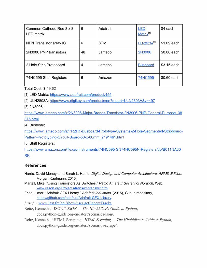
Common Cathode Red 8 x 8 LED matrix
6 Adafruit LED Matrix[1]
$4 each
NPN Transistor array IC 6 STM ULN2803A[2] $1.09 each
2N3906 PNP transistors 48 Jameco 2N3906 $0.06 each
2 Hole Strip Protoboard 4 Jameco Busboard $3.15 each
74HC595 Shift Registers 6 Amazon 74HC595 $0.60 each
Total Cost: $ 49.62 [1] LED Matrix: https://www.adafruit.com/product/455 [2] ULN2803A: https://www.digikey.com/products/en?mpart=ULN2803A&v=497 [3] 2N3906: https://www.jameco.com/z/2N3906-Major-Brands-Transistor-2N3906-PNP-General-Purpose_38375.html [4] Busboard: https://www.jameco.com/z/PR2H1-Busboard-Prototype-Systems-2-Hole-Segmented-Stripboard-Pattern-Prototyping-Circuit-Board-50-x-80mm_2191461.html [5] Shift Registers: https://www.amazon.com/Texas-Instruments-74HC595-SN74HC595N-Registers/dp/B011NA30RK
References:
Harris, David Money, and Sarah L. Harris. Digital Design and Computer Architecture: ARM® Edition . Morgan Kaufmann, 2015.
Martell, Mike. “Using Transistors As Switches.” Radio Amateur Society of Norwich , Web. www.rason.org/Projects/transwit/transwit.htm.
Fried, Limor. “Adafruit GFX Library.” Adafruit Industries, (2015), Github repository, https://github.com/adafruit/Adafruit-GFX-Library.
Last.fm , www.last.fm/api/show/user.getRecentTracks . Reitz, Kenneth . “JSON.” JSON — The Hitchhiker's Guide to Python ,
docs.python-guide.org/en/latest/scenarios/json/. Reitz, Kenneth . “HTML Scraping.” HTML Scraping — The Hitchhiker's Guide to Python ,
docs.python-guide.org/en/latest/scenarios/scrape/.
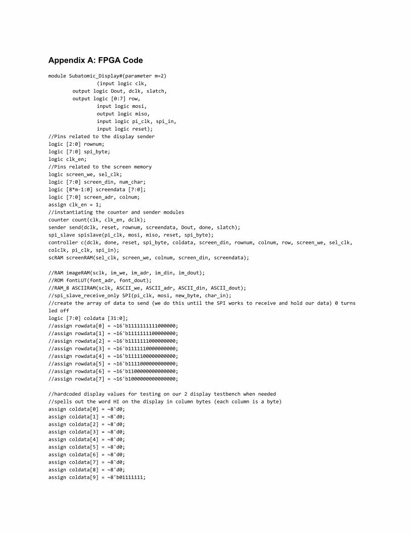
Appendix A: FPGA Code
module Subatomic_Display#(parameter m=2) (input logic clk,
output logic Dout, dclk, slatch, output logic [0:7] row,
input logic mosi, output logic miso, input logic pi_clk, spi_in, input logic reset);
//Pins related to the display sender logic [2:0] rownum; logic [7:0] spi_byte; logic clk_en; //Pins related to the screen memory logic screen_we, sel_clk; logic [7:0] screen_din, num_char; logic [8*m-1:0] screendata [7:0]; logic [7:0] screen_adr, colnum; assign clk_en = 1; //instantiating the counter and sender modules counter count(clk, clk_en, dclk); sender send(dclk, reset, rownum, screendata, Dout, done, slatch); spi_slave spislave(pi_clk, mosi, miso, reset, spi_byte); controller c(dclk, done, reset, spi_byte, coldata, screen_din, rownum, colnum, row, screen_we, sel_clk, colclk, pi_clk, spi_in); scRAM screenRAM(sel_clk, screen_we, colnum, screen_din, screendata);
//RAM imageRAM(sclk, im_we, im_adr, im_din, im_dout); //ROM fontLUT(font_adr, font_dout); //RAM_8 ASCIIRAM(sclk, ASCII_we, ASCII_adr, ASCII_din, ASCII_dout); //spi_slave_receive_only SPI(pi_clk, mosi, new_byte, char_in); //create the array of data to send (we do this until the SPI works to receive and hold our data) 0 turns led off logic [7:0] coldata [31:0]; //assign rowdata[0] = ~16'b1111111111000000; //assign rowdata[1] = ~16'b1111111100000000; //assign rowdata[2] = ~16'b1111111000000000; //assign rowdata[3] = ~16'b1111110000000000; //assign rowdata[4] = ~16'b1111100000000000; //assign rowdata[5] = ~16'b1111000000000000; //assign rowdata[6] = ~16'b1100000000000000; //assign rowdata[7] = ~16'b1000000000000000;
//hardcoded display values for testing on our 2 display testbench when needed //spells out the word HI on the display in column bytes (each column is a byte) assign coldata[0] = ~8'd0; assign coldata[1] = ~8'd0; assign coldata[2] = ~8'd0; assign coldata[3] = ~8'd0; assign coldata[4] = ~8'd0; assign coldata[5] = ~8'd0; assign coldata[6] = ~8'd0; assign coldata[7] = ~8'd0;
assign coldata[8] = ~8'd0; assign coldata[9] = ~8'b01111111;
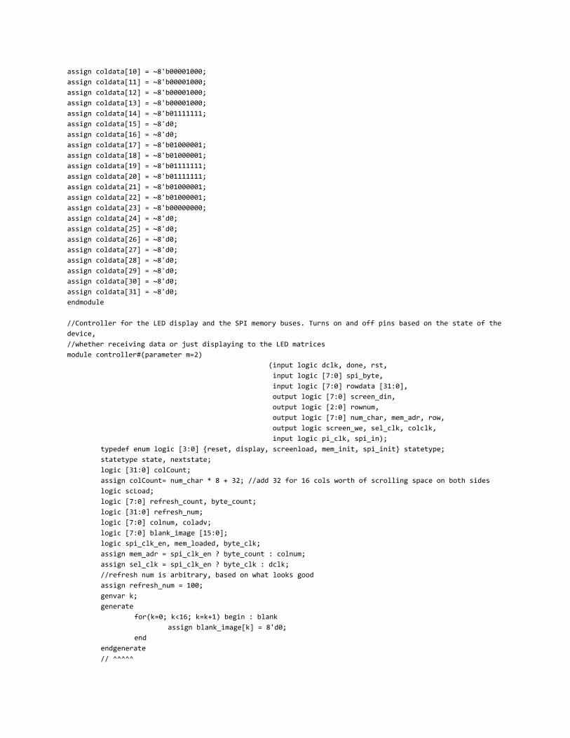
assign coldata[10] = ~8'b00001000; assign coldata[11] = ~8'b00001000; assign coldata[12] = ~8'b00001000; assign coldata[13] = ~8'b00001000; assign coldata[14] = ~8'b01111111; assign coldata[15] = ~8'd0; assign coldata[16] = ~8'd0; assign coldata[17] = ~8'b01000001; assign coldata[18] = ~8'b01000001; assign coldata[19] = ~8'b01111111; assign coldata[20] = ~8'b01111111; assign coldata[21] = ~8'b01000001; assign coldata[22] = ~8'b01000001; assign coldata[23] = ~8'b00000000; assign coldata[24] = ~8'd0; assign coldata[25] = ~8'd0; assign coldata[26] = ~8'd0; assign coldata[27] = ~8'd0; assign coldata[28] = ~8'd0; assign coldata[29] = ~8'd0; assign coldata[30] = ~8'd0; assign coldata[31] = ~8'd0; endmodule
//Controller for the LED display and the SPI memory buses. Turns on and off pins based on the state of the device,
//whether receiving data or just displaying to the LED matrices module controller#(parameter m=2)
(input logic dclk, done, rst, input logic [7:0] spi_byte, input logic [7:0] rowdata [31:0], output logic [7:0] screen_din, output logic [2:0] rownum, output logic [7:0] num_char, mem_adr, row, output logic screen_we, sel_clk, colclk, input logic pi_clk, spi_in);
typedef enum logic [3:0] {reset, display, screenload, mem_init, spi_init} statetype; statetype state, nextstate; logic [31:0] colCount; assign colCount= num_char * 8 + 32; //add 32 for 16 cols worth of scrolling space on both sides logic scLoad; logic [7:0] refresh_count, byte_count; logic [31:0] refresh_num; logic [7:0] colnum, coladv; logic [7:0] blank_image [15:0]; logic spi_clk_en, mem_loaded, byte_clk; assign mem_adr = spi_clk_en ? byte_count : colnum; assign sel_clk = spi_clk_en ? byte_clk : dclk; //refresh num is arbitrary, based on what looks good assign refresh_num = 100; genvar k; generate
for(k=0; k<16; k=k+1) begin : blank assign blank_image[k] = 8'd0;
end
endgenerate
// ^^^^^
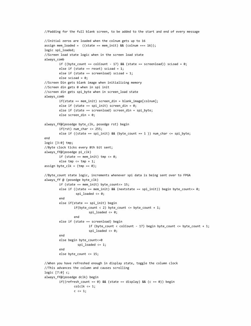
//Padding for the full blank screen, to be added to the start and end of every message
//Initial zeros are loaded when the colnum gets up to 16 assign mem_loaded = ((state == mem_init) && (colnum === 16)); logic spi_loaded; //Screen load state logic when in the screen load state always_comb
if ((byte_count == colCount - 17) && (state == screenload)) scLoad = 0; else if (state == reset) scLoad = 1; else if (state == screenload) scLoad = 1; else scLoad = 0;
//Screen Din gets blank image when initializing memory //Screen din gets 0 when in spi init //screen din gets spi_byte when in screen_load state always_comb
if(state == mem_init) screen_din = blank_image[colnum]; else if (state == spi_init) screen_din = 0; else if (state == screenload) screen_din = spi_byte; else screen_din = 0;
always_ff@(posedge byte_clk, posedge rst) begin if(rst) num_char <= 255; else if ((state == spi_init) && (byte_count == 1 )) num_char <= spi_byte;
end
logic [3:0] tmp; //Byte clock ticks every 8th bit sent; always_ff@(posedge pi_clk)
if (state == mem_init) tmp <= 0; else tmp <= tmp + 1;
assign byte_clk = (tmp == 0);
//Byte_count state logic, increments whenever spi data is being sent over to FPGA always_ff @ (posedge byte_clk)
if (state == mem_init) byte_count<= 15; else if ((state == mem_init) && (nextstate == spi_init)) begin byte_count<= 0;
spi_loaded <= 0;end
else if(state == spi_init) beginif(byte_count < 2) byte_count <= byte_count + 1;
spi_loaded <= 0; end
else if (state == screenload) begin if (byte_count < colCount - 17) begin byte_count <= byte_count + 1;spi_loaded <= 0;
end
else begin byte_count<=0 spi_loaded <= 1;
end
else byte_count <= 15;
//When you have refreshed enough in display state, toggle the column clock //This advances the column and causes scrolling logic [7:0] c; always_ff@(posedge dclk) begin
if((refresh_count == 0) && (state == display) && (c == 0)) begin colclk <= 1; c <= 1;
end
else if ((refresh_count == 0) && (state == display) && (c < 142)) begin //142 is based on testing with the scope to get colclk to be on for only one period
colclk <= 0; c <= c + 1;
end
else begin colclk <= 0; c <= 0;
end
end
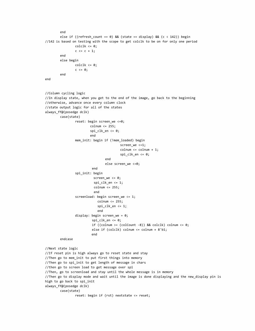
//Column cycling logic //In display state, when you get to the end of the image, go back to the beginning //otherwise, advance once every column clock //state output logic for all of the states always_ff@(posedge dclk)
case(state)
reset: begin screen_we <=0; colnum <= 255; spi_clk_en <= 0; end
mem_init: begin if (!mem_loaded) begin screen_we <=1; colnum <= colnum + 1; spi_clk_en <= 0;
end
else screen_we <=0;
end spi_init: begin screen_we <= 0;
spi_clk_en <= 1; colnum <= 255; end
screenload: begin screen_we <= 1; colnum <= 255; spi_clk_en <= 1;
end display: begin screen_we = 0;
spi_clk_en <= 0; if ((colnum >= (colCount -8)) && colclk) colnum <= 0; else if (colclk) colnum <= colnum + 8'b1;
end endcase
//Next state logic //If reset pin is high always go to reset state and stay //Then go to mem_init to put first things into memory //Then go to spi_init to get length of message in chars //then go to screen load to get message over spi //Then, go to screenload and stay until the whole message is in memory //Then go to display mode and wait until the image is done displaying and the new_display pin is high to go back to spi_init always_ff@(posedge dclk)
case(state)
reset: begin if (rst) nextstate <= reset;
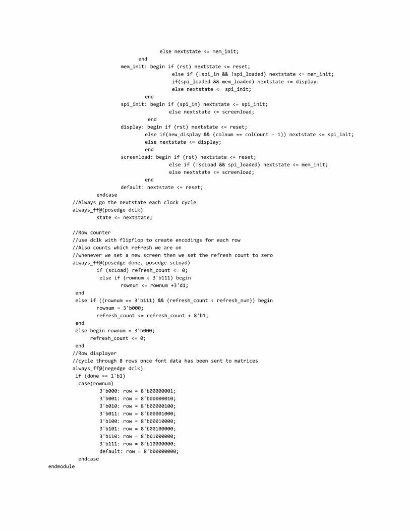
else nextstate <= mem_init; end mem_init: begin if (rst) nextstate <= reset;
else if (!spi_in && !spi_loaded) nextstate <= mem_init; if(spi_loaded && mem_loaded) nextstate <= display; else nextstate <= spi_init;
end
spi_init: begin if (spi_in) nextstate <= spi_init; else nextstate <= screenload;
end display: begin if (rst) nextstate <= reset;
else if(new_display && (colnum == colCount - 1)) nextstate <= spi_init; else nextstate <= display; end
screenload: begin if (rst) nextstate <= reset; else if (!scLoad && spi_loaded) nextstate <= mem_init; else nextstate <= screenload;
end
default: nextstate <= reset; endcase
//Always go the nextstate each clock cycle always_ff@(posedge dclk)
state <= nextstate;
//Row counter //use dclk with flipflop to create encodings for each row //Also counts which refresh we are on //whenever we set a new screen then we set the refresh count to zero always_ff@(posedge done, posedge scLoad) if (scLoad) refresh_count <= 0;
else if (rownum < 3'b111) begin rownum <= rownum +3'd1;
end else if ((rownum == 3'b111) && (refresh_count < refresh_num)) begin
rownum = 3'b000; refresh_count <= refresh_count + 8'b1;
end else begin rownum = 3'b000; refresh_count <= 0; end //Row displayer //cycle through 8 rows once font data has been sent to matrices always_ff@(negedge dclk) if (done == 1'b1) case(rownum)
3'b000: row = 8'b00000001; 3'b001: row = 8'b00000010; 3'b010: row = 8'b00000100; 3'b011: row = 8'b00001000; 3'b100: row = 8'b00010000; 3'b101: row = 8'b00100000; 3'b110: row = 8'b01000000; 3'b111: row = 8'b10000000; default: row = 8'b00000000;
endcase
endmodule
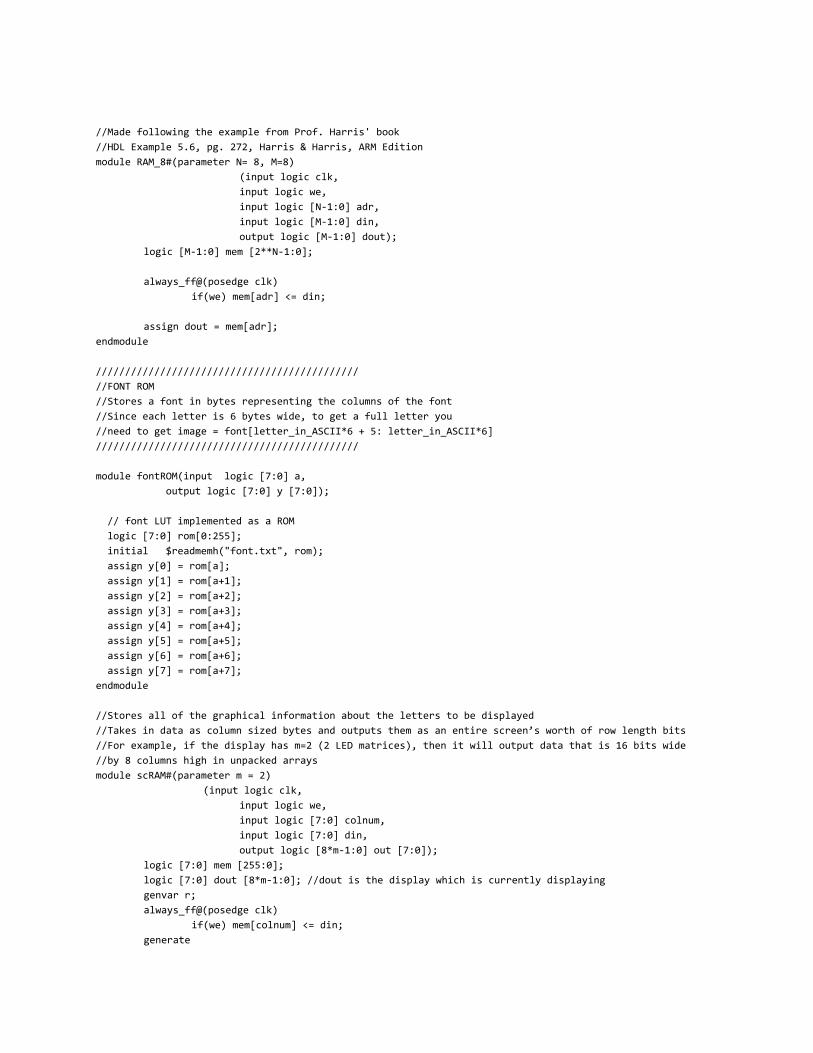
//Made following the example from Prof. Harris' book //HDL Example 5.6, pg. 272, Harris & Harris, ARM Edition module RAM_8#(parameter N= 8, M=8)
(input logic clk, input logic we, input logic [N-1:0] adr, input logic [M-1:0] din, output logic [M-1:0] dout);
logic [M-1:0] mem [2**N-1:0];
always_ff@(posedge clk) if(we) mem[adr] <= din;
assign dout = mem[adr]; endmodule
/////////////////////////////////////////////
//FONT ROM //Stores a font in bytes representing the columns of the font //Since each letter is 6 bytes wide, to get a full letter you //need to get image = font[letter_in_ASCII*6 + 5: letter_in_ASCII*6] /////////////////////////////////////////////
module fontROM(input logic [7:0] a, output logic [7:0] y [7:0]);
// font LUT implemented as a ROM logic [7:0] rom[0:255]; initial $readmemh("font.txt", rom); assign y[0] = rom[a]; assign y[1] = rom[a+1]; assign y[2] = rom[a+2]; assign y[3] = rom[a+3]; assign y[4] = rom[a+4]; assign y[5] = rom[a+5]; assign y[6] = rom[a+6]; assign y[7] = rom[a+7]; endmodule
//Stores all of the graphical information about the letters to be displayed //Takes in data as column sized bytes and outputs them as an entire screen’s worth of row length bits //For example, if the display has m=2 (2 LED matrices), then it will output data that is 16 bits wide //by 8 columns high in unpacked arrays module scRAM#(parameter m = 2)
(input logic clk, input logic we, input logic [7:0] colnum, input logic [7:0] din, output logic [8*m-1:0] out [7:0]);
logic [7:0] mem [255:0]; logic [7:0] dout [8*m-1:0]; //dout is the display which is currently displaying genvar r; always_ff@(posedge clk)
if(we) mem[colnum] <= din; generate
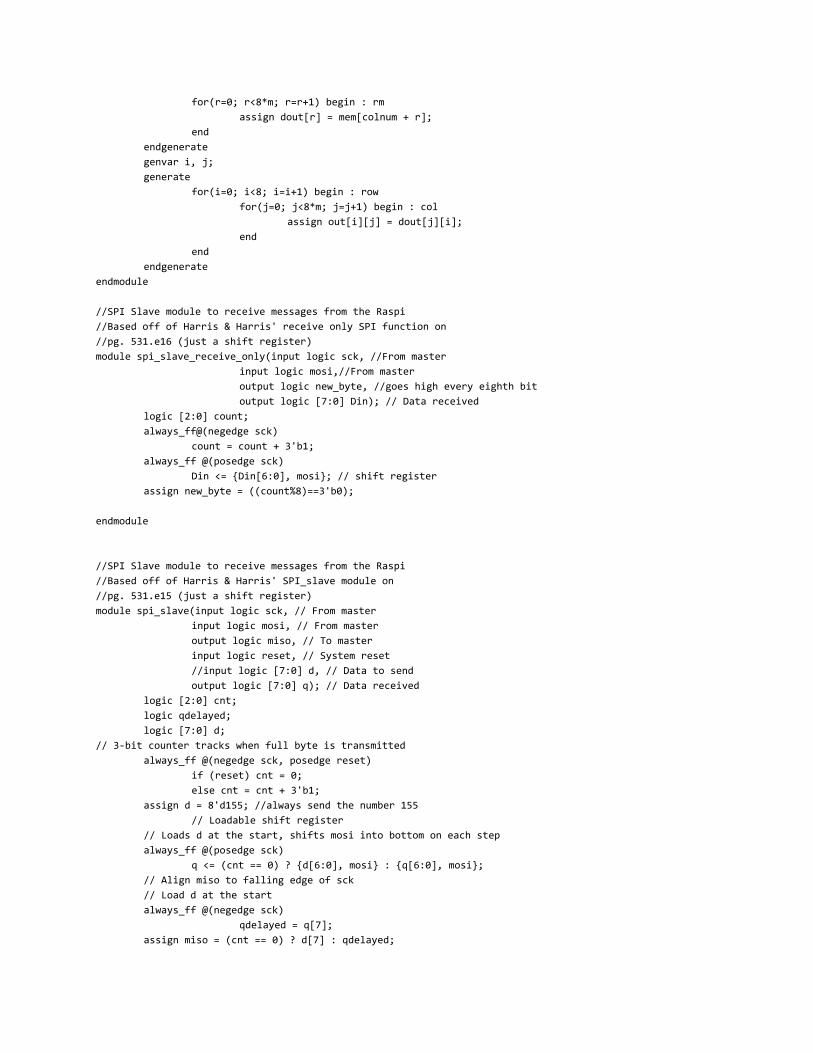
for(r=0; r<8*m; r=r+1) begin : rm assign dout[r] = mem[colnum + r];
end
endgenerate
genvar i, j; generate
for(i=0; i<8; i=i+1) begin : row for(j=0; j<8*m; j=j+1) begin : col
assign out[i][j] = dout[j][i]; end
end
endgenerate
endmodule
//SPI Slave module to receive messages from the Raspi //Based off of Harris & Harris' receive only SPI function on //pg. 531.e16 (just a shift register) module spi_slave_receive_only(input logic sck, //From master
input logic mosi,//From master output logic new_byte, //goes high every eighth bit output logic [7:0] Din); // Data received
logic [2:0] count; always_ff@(negedge sck)
count = count + 3'b1; always_ff @(posedge sck)
Din <= {Din[6:0], mosi}; // shift register assign new_byte = ((count%8)==3'b0);
endmodule
//SPI Slave module to receive messages from the Raspi //Based off of Harris & Harris' SPI_slave module on //pg. 531.e15 (just a shift register)
module spi_slave(input logic sck, // From master input logic mosi, // From master output logic miso, // To master input logic reset, // System reset //input logic [7:0] d, // Data to send output logic [7:0] q); // Data received
logic [2:0] cnt; logic qdelayed; logic [7:0] d;
// 3-bit counter tracks when full byte is transmitted always_ff @(negedge sck, posedge reset)
if (reset) cnt = 0; else cnt = cnt + 3'b1;
assign d = 8'd155; //always send the number 155 // Loadable shift register
// Loads d at the start, shifts mosi into bottom on each step always_ff @(posedge sck)
q <= (cnt == 0) ? {d[6:0], mosi} : {q[6:0], mosi}; // Align miso to falling edge of sck // Load d at the start always_ff @(negedge sck)
qdelayed = q[7]; assign miso = (cnt == 0) ? d[7] : qdelayed;
endmodule
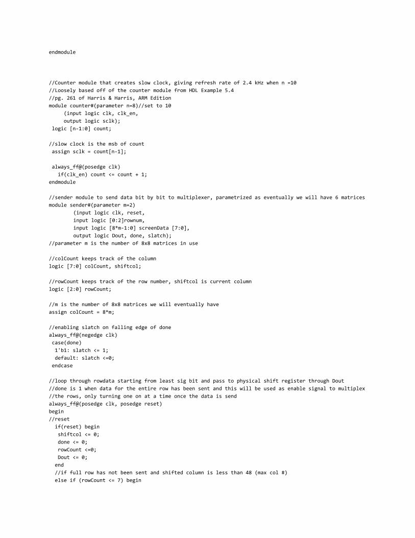
//Counter module that creates slow clock, giving refresh rate of 2.4 kHz when n =10 //Loosely based off of the counter module from HDL Example 5.4 //pg. 261 of Harris & Harris, ARM Edition module counter#(parameter n=8)//set to 10 (input logic clk, clk_en, output logic sclk); logic [n-1:0] count;
//slow clock is the msb of count assign sclk = count[n-1];
always_ff@(posedge clk) if(clk_en) count <= count + 1; endmodule
//sender module to send data bit by bit to multiplexer, parametrized as eventually we will have 6 matrices
module sender#(parameter m=2) (input logic clk, reset, input logic [0:2]rownum, input logic [8*m-1:0] screenData [7:0], output logic Dout, done, slatch); //parameter m is the number of 8x8 matrices in use
//colCount keeps track of the column logic [7:0] colCount, shiftcol;
//rowCount keeps track of the row number, shiftcol is current column logic [2:0] rowCount;
//m is the number of 8x8 matrices we will eventually have assign colCount = 8*m;
//enabling slatch on falling edge of done always_ff@(negedge clk) case(done) 1'b1: slatch <= 1; default: slatch <=0; endcase
//loop through rowdata starting from least sig bit and pass to physical shift register through Dout //done is 1 when data for the entire row has been sent and this will be used as enable signal to multiplex //the rows, only turning one on at a time once the data is send always_ff@(posedge clk, posedge reset) begin
//reset
if(reset) begin shiftcol <= 0; done <= 0; rowCount <=0; Dout <= 0; end //if full row has not been sent and shifted column is less than 48 (max col #) else if (rowCount <= 7) begin
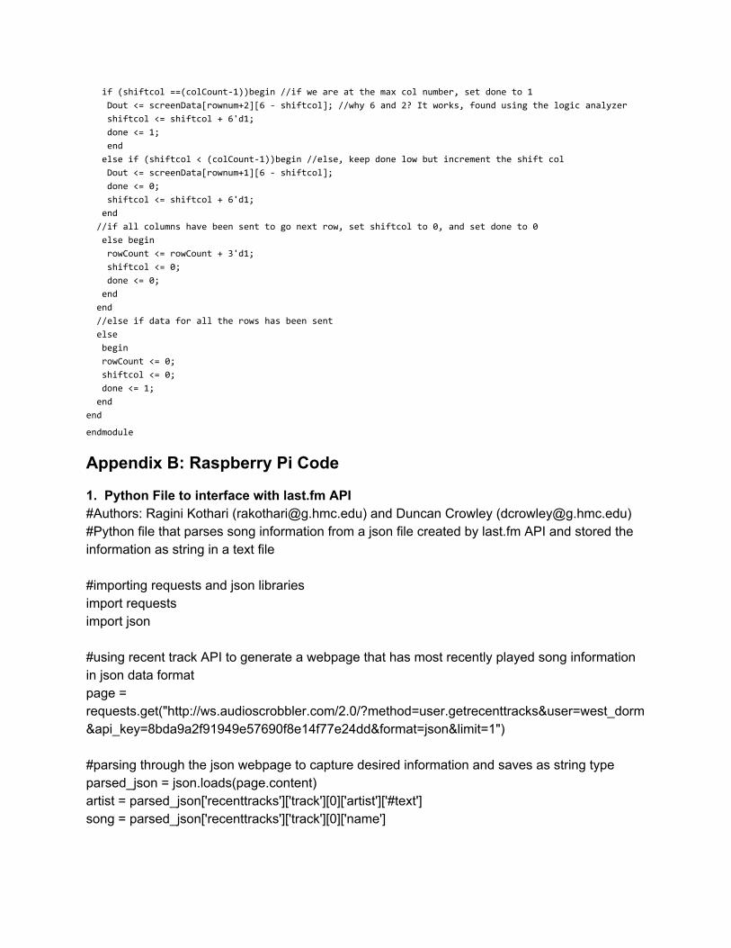
if (shiftcol ==(colCount-1))begin //if we are at the max col number, set done to 1 Dout <= screenData[rownum+2][6 - shiftcol]; //why 6 and 2? It works, found using the logic analyzer shiftcol <= shiftcol + 6'd1; done <= 1; end else if (shiftcol < (colCount-1))begin //else, keep done low but increment the shift col Dout <= screenData[rownum+1][6 - shiftcol]; done <= 0; shiftcol <= shiftcol + 6'd1; end //if all columns have been sent to go next row, set shiftcol to 0, and set done to 0 else begin rowCount <= rowCount + 3'd1; shiftcol <= 0; done <= 0; end end //else if data for all the rows has been sent else begin rowCount <= 0; shiftcol <= 0; done <= 1; end end
endmodule
Appendix B: Raspberry Pi Code
1. Python File to interface with last.fm API
#Authors: Ragini Kothari ([email protected]) and Duncan Crowley ([email protected]) #Python file that parses song information from a json file created by last.fm API and stored the information as string in a text file #importing requests and json libraries import requests import json #using recent track API to generate a webpage that has most recently played song information in json data format page = requests.get("http://ws.audioscrobbler.com/2.0/?method=user.getrecenttracks&user=west_dorm&api_key=8bda9a2f91949e57690f8e14f77e24dd&format=json&limit=1") #parsing through the json webpage to capture desired information and saves as string type parsed_json = json.loads(page.content) artist = parsed_json['recenttracks']['track'][0]['artist']['#text'] song = parsed_json['recenttracks']['track'][0]['name']
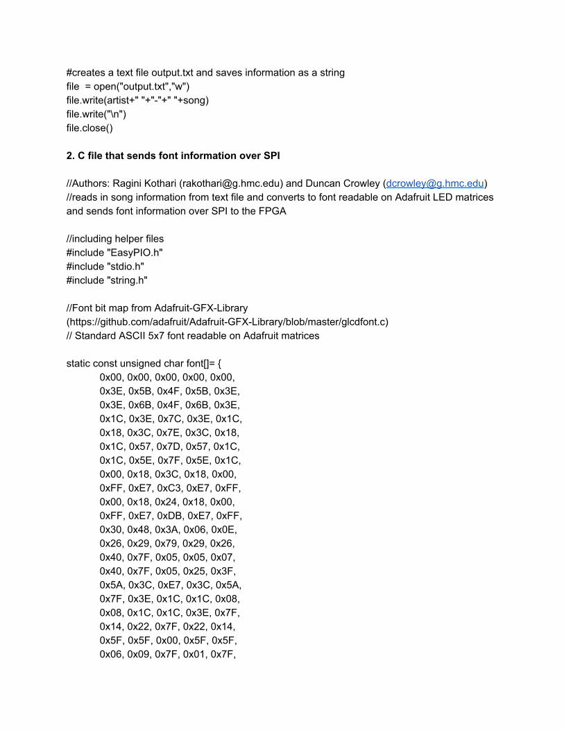
#creates a text file output.txt and saves information as a string file = open("output.txt","w") file.write(artist+" "+"-"+" "+song) file.write("\n") file.close() 2. C file that sends font information over SPI
//Authors: Ragini Kothari ([email protected]) and Duncan Crowley ([email protected] ) //reads in song information from text file and converts to font readable on Adafruit LED matrices and sends font information over SPI to the FPGA //including helper files #include "EasyPIO.h" #include "stdio.h" #include "string.h" //Font bit map from Adafruit-GFX-Library (https://github.com/adafruit/Adafruit-GFX-Library/blob/master/glcdfont.c) // Standard ASCII 5x7 font readable on Adafruit matrices static const unsigned char font[]= {
0x00, 0x00, 0x00, 0x00, 0x00, 0x3E, 0x5B, 0x4F, 0x5B, 0x3E, 0x3E, 0x6B, 0x4F, 0x6B, 0x3E, 0x1C, 0x3E, 0x7C, 0x3E, 0x1C, 0x18, 0x3C, 0x7E, 0x3C, 0x18, 0x1C, 0x57, 0x7D, 0x57, 0x1C, 0x1C, 0x5E, 0x7F, 0x5E, 0x1C, 0x00, 0x18, 0x3C, 0x18, 0x00, 0xFF, 0xE7, 0xC3, 0xE7, 0xFF, 0x00, 0x18, 0x24, 0x18, 0x00, 0xFF, 0xE7, 0xDB, 0xE7, 0xFF, 0x30, 0x48, 0x3A, 0x06, 0x0E, 0x26, 0x29, 0x79, 0x29, 0x26, 0x40, 0x7F, 0x05, 0x05, 0x07, 0x40, 0x7F, 0x05, 0x25, 0x3F, 0x5A, 0x3C, 0xE7, 0x3C, 0x5A, 0x7F, 0x3E, 0x1C, 0x1C, 0x08, 0x08, 0x1C, 0x1C, 0x3E, 0x7F, 0x14, 0x22, 0x7F, 0x22, 0x14, 0x5F, 0x5F, 0x00, 0x5F, 0x5F, 0x06, 0x09, 0x7F, 0x01, 0x7F,
0x00, 0x66, 0x89, 0x95, 0x6A, 0x60, 0x60, 0x60, 0x60, 0x60, 0x94, 0xA2, 0xFF, 0xA2, 0x94, 0x08, 0x04, 0x7E, 0x04, 0x08, 0x10, 0x20, 0x7E, 0x20, 0x10, 0x08, 0x08, 0x2A, 0x1C, 0x08, 0x08, 0x1C, 0x2A, 0x08, 0x08, 0x1E, 0x10, 0x10, 0x10, 0x10, 0x0C, 0x1E, 0x0C, 0x1E, 0x0C, 0x30, 0x38, 0x3E, 0x38, 0x30, 0x06, 0x0E, 0x3E, 0x0E, 0x06, 0x00, 0x00, 0x00, 0x00, 0x00, 0x00, 0x00, 0x5F, 0x00, 0x00, 0x00, 0x07, 0x00, 0x07, 0x00, 0x14, 0x7F, 0x14, 0x7F, 0x14, 0x24, 0x2A, 0x7F, 0x2A, 0x12, 0x23, 0x13, 0x08, 0x64, 0x62, 0x36, 0x49, 0x56, 0x20, 0x50, 0x00, 0x08, 0x07, 0x03, 0x00, 0x00, 0x1C, 0x22, 0x41, 0x00, 0x00, 0x41, 0x22, 0x1C, 0x00, 0x2A, 0x1C, 0x7F, 0x1C, 0x2A, 0x08, 0x08, 0x3E, 0x08, 0x08, 0x00, 0x80, 0x70, 0x30, 0x00, 0x08, 0x08, 0x08, 0x08, 0x08, 0x00, 0x00, 0x60, 0x60, 0x00, 0x20, 0x10, 0x08, 0x04, 0x02, 0x3E, 0x51, 0x49, 0x45, 0x3E, 0x00, 0x42, 0x7F, 0x40, 0x00, 0x72, 0x49, 0x49, 0x49, 0x46, 0x21, 0x41, 0x49, 0x4D, 0x33, 0x18, 0x14, 0x12, 0x7F, 0x10, 0x27, 0x45, 0x45, 0x45, 0x39, 0x3C, 0x4A, 0x49, 0x49, 0x31, 0x41, 0x21, 0x11, 0x09, 0x07, 0x36, 0x49, 0x49, 0x49, 0x36, 0x46, 0x49, 0x49, 0x29, 0x1E, 0x00, 0x00, 0x14, 0x00, 0x00, 0x00, 0x40, 0x34, 0x00, 0x00, 0x00, 0x08, 0x14, 0x22, 0x41, 0x14, 0x14, 0x14, 0x14, 0x14, 0x00, 0x41, 0x22, 0x14, 0x08, 0x02, 0x01, 0x59, 0x09, 0x06,
0x3E, 0x41, 0x5D, 0x59, 0x4E, 0x7C, 0x12, 0x11, 0x12, 0x7C, 0x7F, 0x49, 0x49, 0x49, 0x36, 0x3E, 0x41, 0x41, 0x41, 0x22, 0x7F, 0x41, 0x41, 0x41, 0x3E, 0x7F, 0x49, 0x49, 0x49, 0x41, 0x7F, 0x09, 0x09, 0x09, 0x01, 0x3E, 0x41, 0x41, 0x51, 0x73, 0x7F, 0x08, 0x08, 0x08, 0x7F, 0x00, 0x41, 0x7F, 0x41, 0x00, 0x20, 0x40, 0x41, 0x3F, 0x01, 0x7F, 0x08, 0x14, 0x22, 0x41, 0x7F, 0x40, 0x40, 0x40, 0x40, 0x7F, 0x02, 0x1C, 0x02, 0x7F, 0x7F, 0x04, 0x08, 0x10, 0x7F, 0x3E, 0x41, 0x41, 0x41, 0x3E, 0x7F, 0x09, 0x09, 0x09, 0x06, 0x3E, 0x41, 0x51, 0x21, 0x5E, 0x7F, 0x09, 0x19, 0x29, 0x46, 0x26, 0x49, 0x49, 0x49, 0x32, 0x03, 0x01, 0x7F, 0x01, 0x03, 0x3F, 0x40, 0x40, 0x40, 0x3F, 0x1F, 0x20, 0x40, 0x20, 0x1F, 0x3F, 0x40, 0x38, 0x40, 0x3F, 0x63, 0x14, 0x08, 0x14, 0x63, 0x03, 0x04, 0x78, 0x04, 0x03, 0x61, 0x59, 0x49, 0x4D, 0x43, 0x00, 0x7F, 0x41, 0x41, 0x41, 0x02, 0x04, 0x08, 0x10, 0x20, 0x00, 0x41, 0x41, 0x41, 0x7F, 0x04, 0x02, 0x01, 0x02, 0x04, 0x40, 0x40, 0x40, 0x40, 0x40, 0x00, 0x03, 0x07, 0x08, 0x00, 0x20, 0x54, 0x54, 0x78, 0x40, 0x7F, 0x28, 0x44, 0x44, 0x38, 0x38, 0x44, 0x44, 0x44, 0x28, 0x38, 0x44, 0x44, 0x28, 0x7F, 0x38, 0x54, 0x54, 0x54, 0x18, 0x00, 0x08, 0x7E, 0x09, 0x02, 0x18, 0xA4, 0xA4, 0x9C, 0x78, 0x7F, 0x08, 0x04, 0x04, 0x78, 0x00, 0x44, 0x7D, 0x40, 0x00, 0x20, 0x40, 0x40, 0x3D, 0x00,
0x7F, 0x10, 0x28, 0x44, 0x00, 0x00, 0x41, 0x7F, 0x40, 0x00, 0x7C, 0x04, 0x78, 0x04, 0x78, 0x7C, 0x08, 0x04, 0x04, 0x78, 0x38, 0x44, 0x44, 0x44, 0x38, 0xFC, 0x18, 0x24, 0x24, 0x18, 0x18, 0x24, 0x24, 0x18, 0xFC, 0x7C, 0x08, 0x04, 0x04, 0x08, 0x48, 0x54, 0x54, 0x54, 0x24, 0x04, 0x04, 0x3F, 0x44, 0x24, 0x3C, 0x40, 0x40, 0x20, 0x7C, 0x1C, 0x20, 0x40, 0x20, 0x1C, 0x3C, 0x40, 0x30, 0x40, 0x3C, 0x44, 0x28, 0x10, 0x28, 0x44, 0x4C, 0x90, 0x90, 0x90, 0x7C, 0x44, 0x64, 0x54, 0x4C, 0x44, 0x00, 0x08, 0x36, 0x41, 0x00, 0x00, 0x00, 0x77, 0x00, 0x00, 0x00, 0x41, 0x36, 0x08, 0x00, 0x02, 0x01, 0x02, 0x04, 0x02, 0x3C, 0x26, 0x23, 0x26, 0x3C, 0x1E, 0xA1, 0xA1, 0x61, 0x12, 0x3A, 0x40, 0x40, 0x20, 0x7A, 0x38, 0x54, 0x54, 0x55, 0x59, 0x21, 0x55, 0x55, 0x79, 0x41, 0x22, 0x54, 0x54, 0x78, 0x42, // a-umlaut 0x21, 0x55, 0x54, 0x78, 0x40, 0x20, 0x54, 0x55, 0x79, 0x40, 0x0C, 0x1E, 0x52, 0x72, 0x12, 0x39, 0x55, 0x55, 0x55, 0x59, 0x39, 0x54, 0x54, 0x54, 0x59, 0x39, 0x55, 0x54, 0x54, 0x58, 0x00, 0x00, 0x45, 0x7C, 0x41, 0x00, 0x02, 0x45, 0x7D, 0x42, 0x00, 0x01, 0x45, 0x7C, 0x40, 0x7D, 0x12, 0x11, 0x12, 0x7D, // A-umlaut 0xF0, 0x28, 0x25, 0x28, 0xF0, 0x7C, 0x54, 0x55, 0x45, 0x00, 0x20, 0x54, 0x54, 0x7C, 0x54, 0x7C, 0x0A, 0x09, 0x7F, 0x49, 0x32, 0x49, 0x49, 0x49, 0x32, 0x3A, 0x44, 0x44, 0x44, 0x3A, // o-umlaut 0x32, 0x4A, 0x48, 0x48, 0x30,
0x3A, 0x41, 0x41, 0x21, 0x7A, 0x3A, 0x42, 0x40, 0x20, 0x78, 0x00, 0x9D, 0xA0, 0xA0, 0x7D, 0x3D, 0x42, 0x42, 0x42, 0x3D, // O-umlaut 0x3D, 0x40, 0x40, 0x40, 0x3D, 0x3C, 0x24, 0xFF, 0x24, 0x24, 0x48, 0x7E, 0x49, 0x43, 0x66, 0x2B, 0x2F, 0xFC, 0x2F, 0x2B, 0xFF, 0x09, 0x29, 0xF6, 0x20, 0xC0, 0x88, 0x7E, 0x09, 0x03, 0x20, 0x54, 0x54, 0x79, 0x41, 0x00, 0x00, 0x44, 0x7D, 0x41, 0x30, 0x48, 0x48, 0x4A, 0x32, 0x38, 0x40, 0x40, 0x22, 0x7A, 0x00, 0x7A, 0x0A, 0x0A, 0x72, 0x7D, 0x0D, 0x19, 0x31, 0x7D, 0x26, 0x29, 0x29, 0x2F, 0x28, 0x26, 0x29, 0x29, 0x29, 0x26, 0x30, 0x48, 0x4D, 0x40, 0x20, 0x38, 0x08, 0x08, 0x08, 0x08, 0x08, 0x08, 0x08, 0x08, 0x38, 0x2F, 0x10, 0xC8, 0xAC, 0xBA, 0x2F, 0x10, 0x28, 0x34, 0xFA, 0x00, 0x00, 0x7B, 0x00, 0x00, 0x08, 0x14, 0x2A, 0x14, 0x22, 0x22, 0x14, 0x2A, 0x14, 0x08, 0x55, 0x00, 0x55, 0x00, 0x55, // #176 (25% block) missing in old code 0xAA, 0x55, 0xAA, 0x55, 0xAA, // 50% block 0xFF, 0x55, 0xFF, 0x55, 0xFF, // 75% block 0x00, 0x00, 0x00, 0xFF, 0x00, 0x10, 0x10, 0x10, 0xFF, 0x00, 0x14, 0x14, 0x14, 0xFF, 0x00, 0x10, 0x10, 0xFF, 0x00, 0xFF, 0x10, 0x10, 0xF0, 0x10, 0xF0, 0x14, 0x14, 0x14, 0xFC, 0x00, 0x14, 0x14, 0xF7, 0x00, 0xFF, 0x00, 0x00, 0xFF, 0x00, 0xFF, 0x14, 0x14, 0xF4, 0x04, 0xFC, 0x14, 0x14, 0x17, 0x10, 0x1F, 0x10, 0x10, 0x1F, 0x10, 0x1F, 0x14, 0x14, 0x14, 0x1F, 0x00, 0x10, 0x10, 0x10, 0xF0, 0x00, 0x00, 0x00, 0x00, 0x1F, 0x10,
0x10, 0x10, 0x10, 0x1F, 0x10, 0x10, 0x10, 0x10, 0xF0, 0x10, 0x00, 0x00, 0x00, 0xFF, 0x10, 0x10, 0x10, 0x10, 0x10, 0x10, 0x10, 0x10, 0x10, 0xFF, 0x10, 0x00, 0x00, 0x00, 0xFF, 0x14, 0x00, 0x00, 0xFF, 0x00, 0xFF, 0x00, 0x00, 0x1F, 0x10, 0x17, 0x00, 0x00, 0xFC, 0x04, 0xF4, 0x14, 0x14, 0x17, 0x10, 0x17, 0x14, 0x14, 0xF4, 0x04, 0xF4, 0x00, 0x00, 0xFF, 0x00, 0xF7, 0x14, 0x14, 0x14, 0x14, 0x14, 0x14, 0x14, 0xF7, 0x00, 0xF7, 0x14, 0x14, 0x14, 0x17, 0x14, 0x10, 0x10, 0x1F, 0x10, 0x1F, 0x14, 0x14, 0x14, 0xF4, 0x14, 0x10, 0x10, 0xF0, 0x10, 0xF0, 0x00, 0x00, 0x1F, 0x10, 0x1F, 0x00, 0x00, 0x00, 0x1F, 0x14, 0x00, 0x00, 0x00, 0xFC, 0x14, 0x00, 0x00, 0xF0, 0x10, 0xF0, 0x10, 0x10, 0xFF, 0x10, 0xFF, 0x14, 0x14, 0x14, 0xFF, 0x14, 0x10, 0x10, 0x10, 0x1F, 0x00, 0x00, 0x00, 0x00, 0xF0, 0x10, 0xFF, 0xFF, 0xFF, 0xFF, 0xFF, 0xF0, 0xF0, 0xF0, 0xF0, 0xF0, 0xFF, 0xFF, 0xFF, 0x00, 0x00, 0x00, 0x00, 0x00, 0xFF, 0xFF, 0x0F, 0x0F, 0x0F, 0x0F, 0x0F, 0x38, 0x44, 0x44, 0x38, 0x44, 0xFC, 0x4A, 0x4A, 0x4A, 0x34, // sharp-s or beta 0x7E, 0x02, 0x02, 0x06, 0x06, 0x02, 0x7E, 0x02, 0x7E, 0x02, 0x63, 0x55, 0x49, 0x41, 0x63, 0x38, 0x44, 0x44, 0x3C, 0x04, 0x40, 0x7E, 0x20, 0x1E, 0x20, 0x06, 0x02, 0x7E, 0x02, 0x02, 0x99, 0xA5, 0xE7, 0xA5, 0x99, 0x1C, 0x2A, 0x49, 0x2A, 0x1C, 0x4C, 0x72, 0x01, 0x72, 0x4C, 0x30, 0x4A, 0x4D, 0x4D, 0x30,
0x30, 0x48, 0x78, 0x48, 0x30, 0xBC, 0x62, 0x5A, 0x46, 0x3D, 0x3E, 0x49, 0x49, 0x49, 0x00, 0x7E, 0x01, 0x01, 0x01, 0x7E, 0x2A, 0x2A, 0x2A, 0x2A, 0x2A, 0x44, 0x44, 0x5F, 0x44, 0x44, 0x40, 0x51, 0x4A, 0x44, 0x40, 0x40, 0x44, 0x4A, 0x51, 0x40, 0x00, 0x00, 0xFF, 0x01, 0x03, 0xE0, 0x80, 0xFF, 0x00, 0x00, 0x08, 0x08, 0x6B, 0x6B, 0x08, 0x36, 0x12, 0x36, 0x24, 0x36, 0x06, 0x0F, 0x09, 0x0F, 0x06, 0x00, 0x00, 0x18, 0x18, 0x00, 0x00, 0x00, 0x10, 0x10, 0x00, 0x30, 0x40, 0xFF, 0x01, 0x01, 0x00, 0x1F, 0x01, 0x01, 0x1E, 0x00, 0x19, 0x1D, 0x17, 0x12, 0x00, 0x3C, 0x3C, 0x3C, 0x3C, 0x00, 0x00, 0x00, 0x00, 0x00 // #255 NBSP
}; void int main(){
char output[60]; //reads in output.txt which has current song information scanf("%[^\n]s", &output); printf("%s", output); int i; int c; Int j; char line[60];
//uses char bitmap to create bitmap readable font from string in text file; modified from (https://github.com/adafruit/Adafruit-GFX-Library/blob/master/Adafruit_GFX.cpp)
for (c=0; c < strlen(output); c++){ for (i=0; i<5; i++ ) { // Char bitmap = 5 columns
line[c] = font([output[c] * 5 + i]); }
} char received[60]; char length; pioInit();
//intitializing the SPI with pi_clk of 100000 Hz spiInit(100000,0); pinMode(5,OUTPUT); //Puts FPGA into SPI init state digitalWrite(5, HIGH); delaymillis(2); //gives FPGA time to be in correct state //send length of message length = spiSendReceive(strlen(output)); //might need to modify to strlen -1 bc of new
line at the end of song info //check that received == some check number (155 for now) digitalWrite(5, LOW); //puts us into SPI receive mode //looping through to send whole message with spiSendReceive function from EasyPIO.h for (j=0; j < strlen(output); j++){
received[j] = spiSendReceive(line[j]); } return 0;
}


![Jaké LED osvětlení - Philips · led-hl [≈h1] led-hl [≈h4] led-hl [≈h7] led-t10 [≈w5w] led-amber [≈py21w] led-amber [≈wy21w] led-t10 [≈w5w] led-t10 [≈w5w] canbus](https://img.dokumen.tips/doc/110x75/5f734883e84b6e4bdd0dcf25/jak-led-osvtlen-philips-led-hl-ah1-led-hl-ah4-led-hl-ah7-led-t10.jpg)