Embed Size (px)
Citation preview

HOT WATER MODELS V-33 THROUGH V-180INSTALLATION AND OPERATING INSTRUCTIONS
GAS-FIRED CAST-IRON BOILERS FOR NATURAL AND L.P. PROPANE GASES
CONTENTS . . . . . . . . . . . . . . . . . . . . . . . . . . . . . . . .PAGE
Ratings and Dimensions . . . . . . . . . . . . . . . . . . . . . . . . . .2
Installation Requirements:
Boiler Location . . . . . . . . . . . . . . . . . . . . . . . . . . . . . . . .3
Boiler Foundation . . . . . . . . . . . . . . . . . . . . . . . . . . . . .3
Minimum Clearance . . . . . . . . . . . . . . . . . . . . . . . . . . . .3
Venting Requirements . . . . . . . . . . . . . . . . . . . . . . . . . .3
Chimney and Type “B” Venting . . . . . . . . . . . . . . . . . . .4
Horizontal Venting . . . . . . . . . . . . . . . . . . . . . . . . . . . . .5
Vertical Venting . . . . . . . . . . . . . . . . . . . . . . . . . . . . . . .6
Regular Inspection . . . . . . . . . . . . . . . . . . . . . . . . . .6
Gas Piping . . . . . . . . . . . . . . . . . . . . . . . . . . . . . . . . . . .6
Electrical Controls and Wiring . . . . . . . . . . . . . . . . .11
Boiler Room Air Supply and Ventilation . . . . . . . . . . . .11
Water Piping . . . . . . . . . . . . . . . . . . . . . . . . . . . . . . . . .11
Operating Instructions:
Filling and Venting Water Systems . . . . . . . . . . . . . . . .12
Initial Start, Safety and Lighting Instructions . . . . . . . .12
IID System with Honeywell VR8204 or VR8304 . . .12
Burner Adjustment, Checking Gas Input . . . . . . . . . . .13
Care and Maintenance:
General Maintenance . . . . . . . . . . . . . . . . . . . . . . . . . .14
Water Level Check . . . . . . . . . . . . . . . . . . . . . . . . . . . .14
Annual Inspection and Cleaning . . . . . . . . . . . . . . .14
Safety Check for Control Systems . . . . . . . . . . . . . . . .15
Protection from Freezing . . . . . . . . . . . . . . . . . . . . .15
Water Treatment . . . . . . . . . . . . . . . . . . . . . . . . . . . . . .15
Appendix A and B . . . . . . . . . . . . . . . . . . . . . . . . . . . . . . .16
Sequence of Operations . . . . . . . . . . . . . . . . . . . . . . . . . .17
Wiring Diagrams . . . . . . . . . . . . . . . . . . . . . . . . . . . . . . . .17
Pump or Valve Zoning of Water Boilers . . . . . . . . . . . . . .18
General Troubleshooting Guide . . . . . . . . . . . . . . . . . . . . .19
Piping a Heating-Cooling System . . . . . . . . . . . . . . . . . . .20
Replacement Parts . . . . . . . . . . . . . . . . . . . . . . . . . . . . . .20
IMPORTANTREAD ALL OF THE FOLLOWINGWARNINGS AND STATEMENTS
BEFORE READING THEINSTALLATION INSTRUCTIONS
WARNINGLIQUEFIED PETROLEUM (L.P.)
PROPANE FIRED GAS BOILERS
Installation location ONLY as permitted in paragraphentitled "LIQUEFIED PETROLEUM (L.P.) PROPANEGAS FIRED BOILER LOCATION" on page 3 of thisinstruction book.
The above warning does not apply to NATURAL gasfired boilers.
The installation must conform to the requirements ofthe authority having jurisdiction or, in the absence ofsuch requirements, to the National Fuel Gas Code,ANSI Z223.1-latest edition. The installation must alsoconform to the additional requirements in this Slant/FinInstruction Book.
In addition where required by the authority having juris-diction, the installation must conform to American Soci-ety of Mechanical Engineers Safety Code forControls and Safety Devices for Automatically FiredBoilers. No. CSD-1.
WARNINGThis boiler, gas piping and accessories must beinstalled, connected, serviced and repaired by atrained, experienced service technician, familiar with allprecautions required for gas fired equipment andlicensed or otherwise qualified, in compliance with theauthority having jurisdiction.
This manual must be left with owner and should behung on or adjacent to the boiler for reference.
Printed in U.S.A. 301 Publication No.V-40Part No. 44-0596 Rev. M
Victory™

2 VICTORY
Dimensions (inches)
Figure 1. Left End View Figure 2. Front View Figure 3. Right End View
NOTE: Height Dimension increases to 30-3/16" and depth dimension increases to 22-1/4" when combustible floor kit is used.
Base AssemblyVictory Boiler
V-33 Natural #48 49 50 50 50 51 51 52 52 52
V-33 Propane #56 56 56 57 57 57 58 59 59 60
V-60 thru V-180 Natural #50 51 51 51 52 52 52 52 53 53
V-60 thru V-180 Propane #57 58 59 59 60 60 61 62 63 63
V-33 2 81⁄8" 145⁄8" 3" — 91⁄2" 190 1⁄2" 1⁄2"
V-60 3 111⁄8" 175⁄8" 3" — 121⁄2" 250 1⁄2" 1⁄2"
V-90 4 141⁄8" 205⁄8" 3" 5" 141⁄2" 310 1⁄2"1⁄2"
V-120 5 171⁄8" 235⁄8" 3" 5" 171⁄2" 365 1⁄2" 1⁄2"
V-150 6 201⁄8" 265⁄8" 3" 5" 201⁄2" 425 1⁄2" 1⁄2"
V-180 7 231⁄8" 295⁄8" 3" 5" 231⁄2" 485 1⁄2" 1⁄2"
BoilerModel
No. ofSections A B D
Pressure Horizontalor Vertical Venting
Natural draft chimneyor type “B” venting
Approx.Total Wt.Full OfWater(lb.)
C = Vent Dia.Size of Gas Line
Connection to Boiler(inches)
Natural Propane
BoilerModel
GasType 2000 3000 4000 5000 6000 7000 8000 9000 10000
OrificeSize for
Sea Level
Orifice Sizes for High AltitudesIncludes 4% Reduction for Each 1000 Feet
Elevation — Feet
Orifice sizes indicated for sea level above are factory installed in boiler unless otherwise specified by the local authority.Orifice table is based on a higher heating value between 1000 Btuh and 1009 Btuh for Natural Gas (see III, page 13, if localhigher heating value exceeds these numbers). See III, page 13, for burner input adjustment.
Gas Manifold
Burners
Pilot
BurnerAccess Door
Gas Valve
VICTORY 3
INSTALLATION REQUIREMENTSThe installation must conform to the requirements of theauthority having jurisdiction or, in the absence of suchrequirements, to the National Fuel Gas Code, ANSI Z223.1-latest edition.This installation must also conform to the additional require-ments in this Slant/Fin instruction book.
NATURAL GAS FIRED BOILER LOCATIONProvide a level, solid foundation for the boiler. Locationshould be as near as possible to chimney or outside wall sothat the flue pipe from boiler is short and direct. (SeeAppendix B for vent terminal location restrictions.) The location should also be such that the gas ignition sys-tem components are protected from water (dripping, spray-ing, rain, etc.) during appliance operation and service (circu-lator replacement, condensate trap, control replacement,etc.).
WARNINGLIQUEFIED PETROLEUM (L.P.) PROPANE FIRED GASBOILER LOCATION
REQUIRES SPECIAL ATTENTIONLiquefied Petroleum (L.P.) propane gas is heavier than air.Therefore, propane boilers, piping, valves must NOT beinstalled in locations where propane leaking from defectiveequipment and piping will "pool" in a basement or otherspace below the leak.
A spark or flame from the boiler or other source may ignitethe accumulated propane gas causing an explosion or fire.Provide a level, solid foundation for the boiler. Locationshould be as near the chimney as possible so that the fluepipe from boiler to chimney is short and direct.The UNIFORM MECHANICAL CODE may be in effect inyour geographic area.The following precautions are cited by the 1994 UNIFORMMECHANICAL CODE, section 304.6:
"LPG Appliances. Liquefied petroleum gas-burningappliances shall not be installed in a pit, basement orsimilar location where heavier-than-air-gas might collect.Appliances so fueled shall not be installed in an above-grade under-floor space or basement unless such loca-tion is provided with an approved means for removal ofunburned gas."
Consult Chapter 5 of the 1994 UNIFORM MECHANICALCODE for design criteria of the "approved" means forremoval of unburned gas.
BOILER FOUNDATION A. Provide a solid, level foundation, capable of supporting
the weight of the boiler filled with water, and extending atleast 2" past the jacket on all sides. See dimensions ofboilers, page 2.
B. For installation on non-combustible floors only*.C. If boiler is to be located over buried conduit containing
electric wires or telephone cables, consult local codes orthe National Board of Fire Underwriters for specificrequirements.
* Installation on combustible flooring allowed only with proper Com-bustible Floor Kit. Kit part number is printed on boiler rating plate.In no case may the boiler be installed on carpeting.
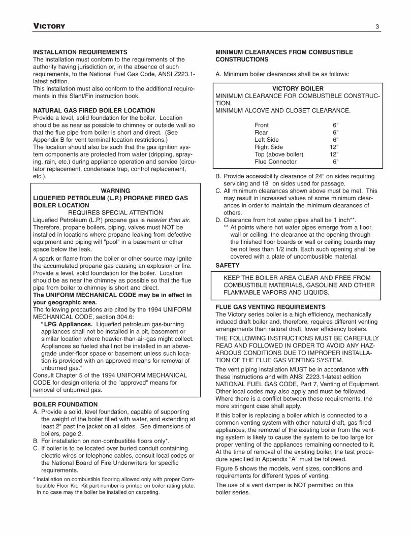
MINIMUM CLEARANCES FROM COMBUSTIBLE CONSTRUCTIONS
A. Minimum boiler clearances shall be as follows:
VICTORY BOILERMINIMUM CLEARANCE FOR COMBUSTIBLE CONSTRUC-TION.MINIMUM ALCOVE AND CLOSET CLEARANCE.
Front 6"Rear 6"Left Side 6"Right Side 12"Top (above boiler) 12"Flue Connector 6"
B. Provide accessibility clearance of 24" on sides requiringservicing and 18" on sides used for passage.
C. All minimum clearances shown above must be met. Thismay result in increased values of some minimum clear-ances in order to maintain the minimum clearances ofothers.
D. Clearance from hot water pipes shall be 1 inch**.** At points where hot water pipes emerge from a floor,
wall or ceiling, the clearance at the opening throughthe finished floor boards or wall or ceiling boards maybe not less than 1/2 inch. Each such opening shall becovered with a plate of uncombustible material.
SAFETYKEEP THE BOILER AREA CLEAR AND FREE FROMCOMBUSTIBLE MATERIALS, GASOLINE AND OTHERFLAMMABLE VAPORS AND LIQUIDS.
FLUE GAS VENTING REQUIREMENTSThe Victory series boiler is a high efficiency, mechanicallyinduced draft boiler and, therefore, requires different ventingarrangements than natural draft, lower efficiency boilers.
THE FOLLOWING INSTRUCTIONS MUST BE CAREFULLYREAD AND FOLLOWED IN ORDER TO AVOID ANY HAZ-ARDOUS CONDITIONS DUE TO IMPROPER INSTALLA-TION OF THE FLUE GAS VENTING SYSTEM.
The vent piping installation MUST be in accordance withthese instructions and with ANSI Z223.1-latest editionNATIONAL FUEL GAS CODE, Part 7, Venting of Equipment.Other local codes may also apply and must be followed.Where there is a conflict between these requirements, themore stringent case shall apply.
If this boiler is replacing a boiler which is connected to acommon venting system with other natural draft, gas firedappliances, the removal of the existing boiler from the vent-ing system is likely to cause the system to be too large forproper venting of the appliances remaining connected to it.At the time of removal of the existing boiler, the test proce-dure specified in Appendix "A" must be followed.
Figure 5 shows the models, vent sizes, conditions andrequirements for different types of venting.
The use of a vent damper is NOT permitted on thisboiler series.
4 VICTORY
Reference Table No. *Appliance Connector Requirements* (ANSI Z223.1)
Victory Boilers Type “B” See table 11-1 for minimum and maximum of vent 11-1(V-90, V-120, V-150 and V-180) height and lateral length restriction.Single appliance
Victory Boiler Single-wall See table 11-2 for minimum and maximum of vent 11-2(V-90, V-120, V-150 and V-180) height and lateral length restriction.Single appliance
Victory Boilers Type “B” 1. See table 11-6 for vent height and connector 11-6(V-90, V-120, V-150 and V-180) length restrictions.plus another gas appliance 2. Connector and vent diameter may have to be in-
creased to 6” or 7” to meet requirement of table 11-6.
Victory Boilers Single-wall 1. See table 11-7 for vent height and connector 11-7(V-120, V-150 and V-180 only) length restrictions.plus another gas appliance 2. Connector and vent diameter may have to be
increased to 6” to meet requirement of table 11-7.
NATURAL DRAFT CHIMNEY AND TYPE “B” VENTINGVICTORY boilers are power (fan assisted) vented boilers. AllVictory boiler models can be PRESSURE side wall or verti-cally vented by connecting the proper 3" diameter vent to the3" diameter collar and adapter factory equipped on theVictory boilers. See “HORIZONTAL PRESSURE VENTING”and “VERTICAL PRESSURE VENTING”.
Models V-33 and V-60 can ONLY be pressure vented asdescribed above and must NOT be vented into a chimney or“B” vent.
Models V-90, V-120, V-150 and V-180 may be vented into anatural draft chimney or natural draft “B” vent if the factoryequipped 3" diameter flue collar and adapter on the boiler isREMOVED and REPLACED by the 5" diameter flue collarmanufactured by Slant/Fin Corporation and included in the V-90 through V-180 shipping crates. (See figures 6a and 6b.)
If the boiler vent is to be installed into a natural draftmasonry chimney or Type “B” venting, it must be inaccordance with National Fuel Gas Code ANSI Z223.1-latest edition, Part 7, Part 11 and Appendix G.
For a masonry vitreous tile-lined chimney which is notexposed to the outdoors, use Table 1 in this Slant/Finmanual for venting requirements. DO NOT install thissystem into an unlined masonry chimney.If a masonry chimney is exposed to the outdoors on oneor more sides below the roof line (exposed chimney), itmust be re-lined with a UL LISTED metallic liner system.See Table 2 in this Slant/Fin manual for venting require-ments of metallic re-lined chimneys.If a Type “B” vent system is used, it must NOT beexposed to the outdoors below the roof line. See Table 2in this Slant/Fin manual for venting requirements. Ventconnectors serving appliances vented by natural draft shallNOT be connected into any portion of mechanical draft sys-tems operating under positive pressure. Single or multipleappliance venting is shown in Figures 6a and 6b.
All Victory boilers require a condensate drain and drain trap.Vent connectors must be liquid tight.
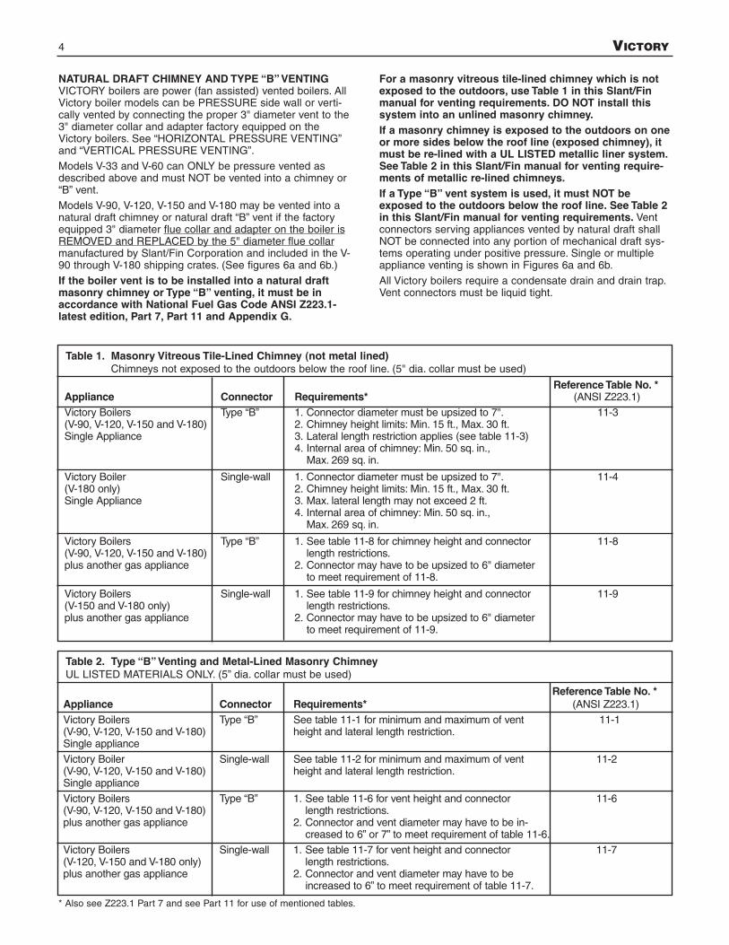
Table 1. Masonry Vitreous Tile-Lined Chimney (not metal lined)Chimneys not exposed to the outdoors below the roof line. (5" dia. collar must be used)
Reference Table No. *Appliance Connector Requirements* (ANSI Z223.1)
Victory Boilers Type “B” 1. Connector diameter must be upsized to 7". 11-3(V-90, V-120, V-150 and V-180) 2. Chimney height limits: Min. 15 ft., Max. 30 ft.Single Appliance 3. Lateral length restriction applies (see table 11-3)
4. Internal area of chimney: Min. 50 sq. in., Max. 269 sq. in.
Victory Boiler Single-wall 1. Connector diameter must be upsized to 7". 11-4(V-180 only) 2. Chimney height limits: Min. 15 ft., Max. 30 ft.Single Appliance 3. Max. lateral length may not exceed 2 ft.
4. Internal area of chimney: Min. 50 sq. in., Max. 269 sq. in.
Victory Boilers Type “B” 1. See table 11-8 for chimney height and connector 11-8(V-90, V-120, V-150 and V-180) length restrictions.plus another gas appliance 2. Connector may have to be upsized to 6" diameter
to meet requirement of 11-8.
Victory Boilers Single-wall 1. See table 11-9 for chimney height and connector 11-9(V-150 and V-180 only) length restrictions.plus another gas appliance 2. Connector may have to be upsized to 6" diameter
to meet requirement of 11-9.
Table 2. Type “B” Venting and Metal-Lined Masonry ChimneyUL LISTED MATERIALS ONLY. (5” dia. collar must be used)
* Also see Z223.1 Part 7 and see Part 11 for use of mentioned tables.

VICTORY 5
HORIZONTAL PRESSURE VENTINGAll VICTORY models are certified for horizontal pressureventing with the following restrictions:1. Vent Material
A. The vent system for horizontal venting must be UL list-ed single wall Saf-T 3" diameter #AL 29-4Cs stainlesssteel manufactured by Heat-Fab, Inc. The manufactur-ers’ part numbers for various items of the vent systemare listed in SLANT/FIN Parts List, Publication # V-10PL.
B. DO NOT use plastic or galvanized flue pipe.
C. For horizontal, through the wall venting, the 3" fluecollar and adapter MUST be used. The vent pipe sizemust be 3" diameter from the boiler to the outside ter-mination. Certain restrictions on the location of thevent terminal are specified in APPENDIX "B" and mustbe followed.
2. InstallationA. Figures 7 and 8 show the allowed venting arrange-
ments. The maximum equivalent vent length is 40 feetplus vent terminal for all models except V-180 whichhas a 20 feet maximum equivalent vent length. Every90° turn in the vent piping is equivalent to 5 feet ofstraight run, (eg. a V-120 system with 3 elbows and theoutside terminal would allow 40 - 15 = 25 feet ofstraight run). The minimum allowable equivalent vent
length is 2 feet and 1 elbow plus vent terminal for allmodels, see table below. NOTE: For best operation,elbows should be at least five diameters apart other-wise maximum vent length should be reduced.
B. When joining the various components of the above list-ed vent systems, the manufacturers’ instructionsshould be closely followed to insure proper sealing.Use GE-RTV 106 or Dow Corning 732 Sealant forsealing of pipe and fittings. See figure 4 for properapplication of vent pipe sealant.
C. All Victory boilers require a condensate drain and draintrap.
The horizontal pipe must be sloped TOWARD the con-densate drain at least 1/4" per 1' of run. The horizontalportion must also be supported with pipe straps atintervals no greater than indicated by vent pipe manu-facturer’s instruction.
Where the vent pipe goes through the outside wall, athimble must be used (see Figures 7 and 8).
Heat-Fab pipes and fittings cannot be cut to length.Use slip joint connector (Heat-Fab part no. 7324GC) toadjust pipe lengths dimensions.
Figure 4. Vent Sealing Instructions(Consult vent manufacturer’s instructions.)
3” Diameter Venting System Restrictions
ModelMinimumLength*
MaximumEquivalent
LengthincludingElbows*
EquivalentLength
of Elbows
MinimumNo. of
Elbows*V-33
to 40 ft. 5 ft. 2 ft. 1V-150
V-180 20 ft. 5 ft. 2 ft. 1
* Vent terminal is in addition to the allowed vent pipe length and elbows.
s: AL 29-4C is a registered trademark of Allegheny Ludlum Corp.
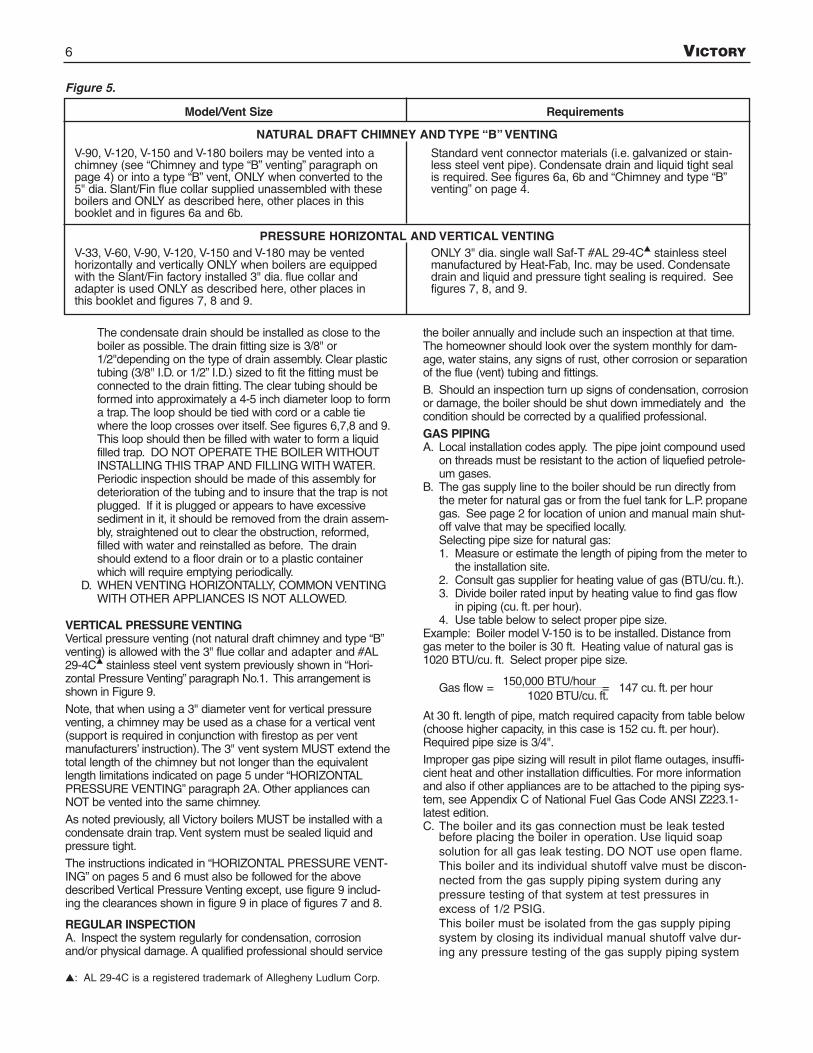
Model/Vent Size
V-90, V-120, V-150 and V-180 boilers may be vented into achimney (see “Chimney and type “B” venting” paragraph onpage 4) or into a type “B” vent, ONLY when converted to the5" dia. Slant/Fin flue collar supplied unassembled with theseboilers and ONLY as described here, other places in thisbooklet and in figures 6a and 6b.
V-33, V-60, V-90, V-120, V-150 and V-180 may be ventedhorizontally and vertically ONLY when boilers are equippedwith the Slant/Fin factory installed 3" dia. flue collar andadapter is used ONLY as described here, other places inthis booklet and figures 7, 8 and 9.
Requirements
Standard vent connector materials (i.e. galvanized or stain-less steel vent pipe). Condensate drain and liquid tight sealis required. See figures 6a, 6b and “Chimney and type “B”venting” on page 4.
ONLY 3" dia. single wall Saf-T #AL 29-4Cs stainless steelmanufactured by Heat-Fab, Inc. may be used. Condensatedrain and liquid and pressure tight sealing is required. Seefigures 7, 8, and 9.
6 VICTORY
The condensate drain should be installed as close to theboiler as possible.The drain fitting size is 3/8" or1/2"depending on the type of drain assembly. Clear plastictubing (3/8" I.D. or 1/2” I.D.) sized to fit the fitting must beconnected to the drain fitting.The clear tubing should beformed into approximately a 4-5 inch diameter loop to forma trap.The loop should be tied with cord or a cable tiewhere the loop crosses over itself. See figures 6,7,8 and 9.This loop should then be filled with water to form a liquidfilled trap. DO NOT OPERATE THE BOILER WITHOUTINSTALLING THIS TRAP AND FILLING WITH WATER.Periodic inspection should be made of this assembly fordeterioration of the tubing and to insure that the trap is notplugged. If it is plugged or appears to have excessivesediment in it, it should be removed from the drain assem-bly, straightened out to clear the obstruction, reformed,filled with water and reinstalled as before. The drainshould extend to a floor drain or to a plastic containerwhich will require emptying periodically.
D. WHEN VENTING HORIZONTALLY, COMMON VENTINGWITH OTHER APPLIANCES IS NOT ALLOWED.
VERTICAL PRESSURE VENTINGVertical pressure venting (not natural draft chimney and type “B”venting) is allowed with the 3" flue collar and adapter and #AL29-4Cs stainless steel vent system previously shown in “Hori-zontal Pressure Venting” paragraph No.1. This arrangement isshown in Figure 9.
Note, that when using a 3" diameter vent for vertical pressureventing, a chimney may be used as a chase for a vertical vent(support is required in conjunction with firestop as per ventmanufacturers’ instruction).The 3" vent system MUST extend thetotal length of the chimney but not longer than the equivalentlength limitations indicated on page 5 under “HORIZONTALPRESSURE VENTING” paragraph 2A. Other appliances canNOT be vented into the same chimney.
As noted previously, all Victory boilers MUST be installed with acondensate drain trap. Vent system must be sealed liquid andpressure tight.
The instructions indicated in “HORIZONTAL PRESSURE VENT-ING” on pages 5 and 6 must also be followed for the abovedescribed Vertical Pressure Venting except, use figure 9 includ-ing the clearances shown in figure 9 in place of figures 7 and 8.
REGULAR INSPECTIONA. Inspect the system regularly for condensation, corrosionand/or physical damage. A qualified professional should service
the boiler annually and include such an inspection at that time.The homeowner should look over the system monthly for dam-age, water stains, any signs of rust, other corrosion or separationof the flue (vent) tubing and fittings.
B. Should an inspection turn up signs of condensation, corrosionor damage, the boiler should be shut down immediately and thecondition should be corrected by a qualified professional.
GAS PIPINGA. Local installation codes apply. The pipe joint compound used
on threads must be resistant to the action of liquefied petrole-um gases.
B. The gas supply line to the boiler should be run directly fromthe meter for natural gas or from the fuel tank for L.P. propanegas. See page 2 for location of union and manual main shut-off valve that may be specified locally.Selecting pipe size for natural gas:1. Measure or estimate the length of piping from the meter to
the installation site.2. Consult gas supplier for heating value of gas (BTU/cu. ft.).3. Divide boiler rated input by heating value to find gas flow
in piping (cu. ft. per hour).4. Use table below to select proper pipe size.
Example: Boiler model V-150 is to be installed. Distance fromgas meter to the boiler is 30 ft. Heating value of natural gas is1020 BTU/cu. ft. Select proper pipe size.
Gas flow = 150,000 BTU/hour = 147 cu. ft. per hour1020 BTU/cu. ft.
At 30 ft. length of pipe, match required capacity from table below(choose higher capacity, in this case is 152 cu. ft. per hour).Required pipe size is 3/4".
Improper gas pipe sizing will result in pilot flame outages, insuffi-cient heat and other installation difficulties. For more informationand also if other appliances are to be attached to the piping sys-tem, see Appendix C of National Fuel Gas Code ANSI Z223.1-latest edition.C. The boiler and its gas connection must be leak tested
before placing the boiler in operation. Use liquid soap solution for all gas leak testing. DO NOT use open flame.This boiler and its individual shutoff valve must be discon-nected from the gas supply piping system during anypressure testing of that system at test pressures inexcess of 1/2 PSIG.This boiler must be isolated from the gas supply pipingsystem by closing its individual manual shutoff valve dur-ing any pressure testing of the gas supply piping system
Figure 5.
s: AL 29-4C is a registered trademark of Allegheny Ludlum Corp.
NATURAL DRAFT CHIMNEY AND TYPE “B” VENTING
PRESSURE HORIZONTAL AND VERTICAL VENTING

VICTORY 7
Figure 6b. Venting with “B” vent or metal-lined chimney for V-90, V-120, V-150 and V-180 onlyMinimum vent connectors diameter is 5 inches. It may have to be upsized to 6 or 7 inches (see Table 2).Single or multiple appliance venting into Type “B” double wall metal vent with single or Type “B” metal connectors, must be installed in accordance with National Fuel Gas Code ANSI Z223.1-latest edition, part 7 and 11. DO NOTuse galvanized risers and connectors in cool boiler rooms.ALL ITEMS SHOWN BELOW ARE REQUIRED EXCEPT WHERE OTHERWISE INDICATED. All vent connector joints must be liquid tight.
Figure 6a. Chimney Venting for V-90, V-120, V-150 and V-180 only.Minimum vent connectors diameter is 5 inches. It may have to be upsized to 6 or 7 inches (see Table 1).Single or multiple appliance venting into chimney using single wall or type “B” metal connectors, must be installed in accordance with National Fuel Gas Code ANSI Z223.1-latest edition, part 7 and 11. See “Chimney and Type “B”Venting” paragraph on page 4 of this manual. DO NOT use galvanized risers and connectors in cool boiler rooms.
ALL ITEMS SHOWN BELOW ARE REQUIRED.All vent connector joints must be LIQUID tight.

8 VICTORY
Figure 7. Horizontal Venting (3 IN.): All Victory ModelsAll items shown below are REQUIRED. All vent joints must be LIQUID and PRESSURE TIGHT.Use only 3" dia. Saf-T vent (#AL 29-4C* stainless steel) venting materials by Heat-Fab Inc.(See both horizontal and vertical venting in this booklet for restrictions).

VICTORY 9
Figure 8. Horizontal Venting (3 IN.): All Victory ModelsAll items shown below are REQUIRED. All vent joints must be LIQUID and PRESSURE TIGHT.Use only 3" dia. Saf-T vent (#AL 29-4C* stainless steel) venting materials by Heat-Fab Inc.(See both horizontal and vertical venting in this booklet for restrictions).

10 VICTORY
Figure 9. Vertical Venting (3 IN.): All Victory ModelsAll items shown below are REQUIRED. All vent joints must be LIQUID and PRESSURE TIGHT.Use only 3" dia. Saf-T vent (#AL 29-4C* stainless steel) venting materials by Heat-Fab Inc.(See both horizontal and vertical venting in this booklet for restrictions).
VICTORY 11
at test pressures equal to or less than 1/2 PSIG.D. All gas piping used should be inspected thoroughly for
cleanliness before makeup. A sediment trap must be pro-vided, as illustrated on page 2.
E. The minimum and maximum gas supply pressure (at theinlet of gas valve) are shown on the boiler rating plate forthe type of gas used. Gas supply pressure should neverbe less than minimum or more than maximum pressurewhen the boiler or any other appliance is turned on or off.
ELECTRICAL CONTROLS AND WIRING A. The electrical power to the boiler must be on a separately
fused and live circuit.B. If an external electrical source is utilized, the boiler, when
installed, must be electrically grounded in accordancewith the requirements of the authority having jurisdictionor, in the absence of such requirements, with the NationalElectrical Code, ANSI/NFPA No. 70-latest edition.
C. Basic control wiring diagrams are given on page 17 and18. Other control systems may be factory supplied: seeUser's Information Manual and instructions packed withcontrol system supplied.
D. After placing the boiler in operation, the safety shutoffdevice must be tested. See page 14 safety check.
BOILER ROOM AIR SUPPLY AND VENTILATIONAn ample supply of air is required to obtain combustion andventilation. ALL AIR COMES FROM OUTSIDE, directlythrough wall openings to the boiler or through unsealedopenings around windows, doors, etc. in the whole building.When buildings are insulated, caulked and weather-stripped,now or later on, direct openings to outside may be requiredand should be provided. If the boiler is not near an outsidewall, air may be ducted to it from outside wall openings.Provisions for combustion and ventilation air must be madein accordance with section 5.3, Air for Combustion and Venti-lation, of the National Fuel Gas Code, ANSI Z223.1-latestedition, or applicable provisions of the local building codes.The following recommendation applies to buildings of ener-gy-saving construction, fully caulked and weather stripped:Provide one GRILLED opening near the floor and one nearthe ceiling on an outside wall near the boiler (or duct fromsuch openings to the boiler), EACH opening to be a mini-mum of one square inch per 2000 Btuh input to ALL APPLI-ANCES in the area. For a total appliance input of 200,000Btuh, each opening will be 100 square inches. A grilled
opening 10"X10" has 100 square inches of area. If flyscreen must be used over openings, double the area andinspect and clean the screen frequently.Openings must never be reduced or closed. If doors or win-dows are used for air supply, they must be locked open.Protect against closure of openings by snow and debris.Inspect frequently.No mechanical draft exhaust or supply fans are to be used inor near the boiler area.The flow of combustion and ventilating air to the boiler mustnot be obstructed.
WATER PIPINGI. CIRCULATING SYSTEMS
A. Packaged water boilers are equipped with a water circu-lating pump, mounted to return the water into the boiler.For some installations, the pump should be on the sup-ply main. See PUMP LOCATION, on page 12.
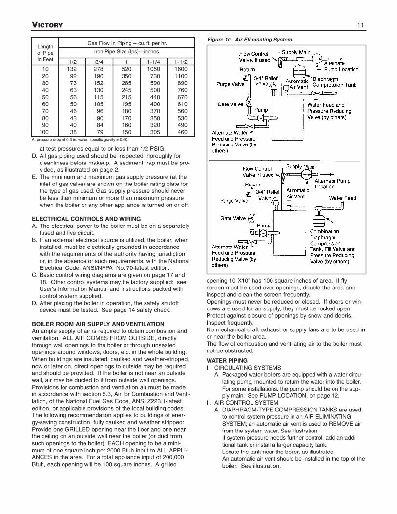
II. AIR CONTROL SYSTEMA. DIAPHRAGM-TYPE COMPRESSION TANKS are used
to control system pressure in an AIR ELIMINATINGSYSTEM; an automatic air vent is used to REMOVE airfrom the system water. See illustration.If system pressure needs further control, add an addi-tional tank or install a larger capacity tank.Locate the tank near the boiler, as illustrated.An automatic air vent should be installed in the top of theboiler. See illustration.
1/2 3/4 1 1-1/4 1-1/210 132 278 520 1050 160020 92 190 350 730 110030 73 152 285 590 89040 63 130 245 500 76050 56 115 215 440 67060 50 105 195 400 61070 46 96 180 370 56080 43 90 170 350 53090 40 84 160 320 490
100 38 79 150 305 460
Lengthof Pipein Feet
Gas Flow In Piping -- cu. ft. per hr.
Iron Pipe Size (Ips)—inches
Figure 10. Air Eliminating System
At pressure drop of 0.3 in. water, specific gravity = 0.60.
12 VICTORY
B. PUMP LOCATION-Locating low-head pump(s) onreturn to boiler is acceptable for smaller boiler sizes inresidences of one or two stories. The alternate pump location shown in illustration on page 11 is required inlarge, multi-story building installations, especially whenhigh-head pumps are used. The compression tankmust be at the boiler or between boiler and supplymain pump(s).
C. On a hot water boiler installed above radiation level,the boiler must be provided with a low water cutoffdevice at the time of installation by the installer.
OPERATING INSTRUCTIONS, BASICI. FILLING AND VENTING WATER SYSTEMS
A. Fill the system with water. Vent or purge of air.B. Fire the boiler as soon as possible (see following warn-
ing and instructions) and bring water temperature to atleast 180 degrees, while circulating water in the sys-tem.
C. Vent air and add water as needed to achieve operatingpressure on boiler gauge. Pressure must be betweenapproximately 12 psi (cold water) and 25 psi at watertemperature setting of high limit control, for boilersequipped with 30 psi relief valves. Boilers rated for ahigher pressure and equipped with a matching reliefvalve may operate at a higher pressure, but no higherthan 5 psi below the relief valve opening pressure.
D. Check for and repair any leaks before placing systemin service.BEFORE FIRING BOILER, make these checks:1. System is full of water. Air is vented or purged.2. Relief valve is installed in accordance with ASME
Boiler and Pressure Vessel Code, Section IV. Valveopening is not closed or reduced in size.
3. Venting is installed according to instructions under“FLUE GAS VENTING REQUIREMENTS”.
4. All wiring is completed, following applicable wiringdiagrams.
5. Using soap solution, check for gas leaks in all gaspiping from meter to boiler pilot and manifold.DO NOT use open flame.
II. INITIAL STARTSafe lighting and other performance criteria were metwhen testing various gas manifold and control assembliesused on the Victory Series Boilers under the ANSIZ21.13- 1987 Standard.
InstructionsFollow the lighting instructions in this manual that apply tothe particular ignition system equipped on this boiler.(Also, see figures on page 2 for location of gas manifold,gas valve and control assembly.) These instructions arealso attached to the boiler.
SAFETY INFORMATIONFor Your Safety Read Before Operating
WARNING: If you do not follow these instructions exactly,a fire or explosion may result causing property damage,personal injury or loss of life.
A. This appliance is equipped with an ignition devicewhich automatically lights the pilot. DO NOT try tolight the pilot by hand.
B. BEFORE OPERATING smell all around the appliancearea for gas. Be sure to smell next to the floor becausesome gas is heavier than air and will settle on thefloor.
WHAT TO DO IF YOU SMELL GAS• DO NOT try to light any appliance.• DO NOT touch any electric switch; DO NOT use
any phone in your building.• Immediately call your gas supplier from a neighbor's
phone. Follow the gas supplier's instructions.• If you cannot reach your gas supplier, call the fire
department.C. Use only your hand to push in or turn the gas control
knob. NEVER use tools. If the knob will not push in orturn by hand, don't try to repair it, call a qualified ser-vice technician. Force or attempted repair may resultin a fire or explosion.
D. DO NOT use this appliance if any part has beenunderwater. Immediately call a qualified service tech-nician to inspect the appliance and to replace any partof the control system and any gas control which hasbeen underwater.
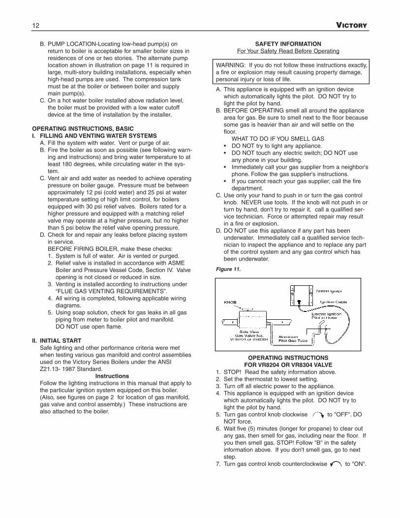
OPERATING INSTRUCTIONSFOR VR8204 OR VR8304 VALVE
1. STOP! Read the safety information above.2. Set the thermostat to lowest setting.3. Turn off all electric power to the appliance.4. This appliance is equipped with an ignition device
which automatically lights the pilot. DO NOT try tolight the pilot by hand.
5. Turn gas control knob clockwise to "OFF". DONOT force.
6. Wait five (5) minutes (longer for propane) to clear outany gas, then smell for gas, including near the floor. Ifyou then smell gas, STOP! Follow "B" in the safetyinformation above. If you don't smell gas, go to nextstep.
7. Turn gas control knob counterclockwise to "ON".
Figure 11.

VICTORY 13
8. Turn on all electric power to the appliance.9. Set thermostat to desired setting.
10. If the appliance will not operate, follow the instructions "To Turn Off Gas To Appliance" and call your service technician or gas supplier.
To Turn Off Gas to Appliance1. Set thermostat to lowest setting.2. Turn off all electric power to the appliance if service is
to be performed.3. Turn gas control knob clockwise to “OFF”.
DO NOT force.
III. BURNER ADJUSTMENTA. Adjust gas input rate:
1. Consult gas supplier for higher heating value of gas(Btu/cu.ft.).
2. Set thermostat high enough so that boiler willremain on while checking rate.
3. Measure manifold pressure at 1/8" tapping. Correctmanifold pressure for gas used is printed on boilerrating plate. NOTE: Gas pressure may be adjustedby turning pressure regulator screw on combinationgas valve (turn clockwise to increase pressure,counterclockwise to decrease pressure).a. Input for PROPANE is approximately at rating
shown on rating plate when manifold pressure is9-1/2" water column.
b. Input for NATURAL GAS is approximately at rat-ing when manifold pressure is 3-1/2" water col-umn, but should be checked on the gas meter:Btuh Input = Btu/cu. ft. x cu. ft. metered in 3 min-utes x 20
Example 1:For 1000 Btu/cu.ft. gas, this becomes:
Btuh Input = cu. ft. metered in 3 minutesx 1,000 Btu/cu.ft. x 20
Example 2:For 1050 Btu/cu.ft. gas, this becomes:
Btuh Input = cu. ft. metered in 3 minutesx 1050 Btu/cu.ft. x 20
4. The higher* heating value of gas varies substantially fordifferent localities. Consult with Slant/Fin’s Technical Ser-vice Dept. for re-orificing procedures if any of the followingapply:
a. Boiler (burner) is overfiring. CAUTION! NationalFuel Gas Code (ANSI Z223.1-latest edition) doesNOT permit firing at a higher input rate than theinput rate indicated on the boiler rating plate inorder to avoid hazardous conditions such as explo-sion or carbon monoxide poisoning.
b. Poor higher* heating value of gas is causing theactual input to be substantially lower than therating plate indication.* “Higher heating” value of gas is commonly
known as “heating value”.The gas metered in 3 minutes to obtain rated input foreach boiler model, using 1000 Btu/cu.ft. gas, is tabulat-ed in gas rate table.
B. Main Burners1. Fire the boiler continuously for at least 15 minutes,
to reach burner operating temperature.2. Observe the flames, all burners. The base of all
flame jets should be blue. The tips should be blueshading to orange. NOTE: Dust, disturbed by anymovement, will cause bright orange flames. Waitfor dust to settle.
3. For one burner, close the air shutter until some ofits flame jet tips turn yellow-white, indicating insuffi-cient primary air. Then open shutter until whitishtips disappear completely. Set all burner shutters tothe same opening. Observe to make sure that noyellow-white tips appear over any portion of theflame. Small yellow tips at the pilot location arepermitted.NOTE: This adjustment method gives MINIMUMprimary air setting for safe combustion. DO NOTattempt to make this adjustment unless burners areat operating temperature. Adjustment should bemade with burner access panel in final operatingposition. Use of a mirror may be helpful to observeflames. Note that burner ports are on top of mainburner tube.
C. Main Burner Ignition Checkout and Pilot Adjustment.1. The pilot flame must not smother or snuff out when
tested as follows:a. Main burner ignition from cold start-repeat.b. Continued operation of main burner.c. Main burner ignition with appliance at maximum
operating temperature after prolonged operation.NOTE: Observe operation of the pilot burner withappliance doors in the final operating position. Useof a mirror may be helpful.
Boiler rated input incu. ft./hr. of 1000 Btu/cu. ft.
Natural Gas336090120150180
Cubic Feet Gas Consumption1000 Btu/cu. ft. gas, in
3 minutes, at rated input1.653.004.506.007.509.00
Figure 12. IID System with Honeywell VR8204 or VR8304Gas Valve
14 VICTORY
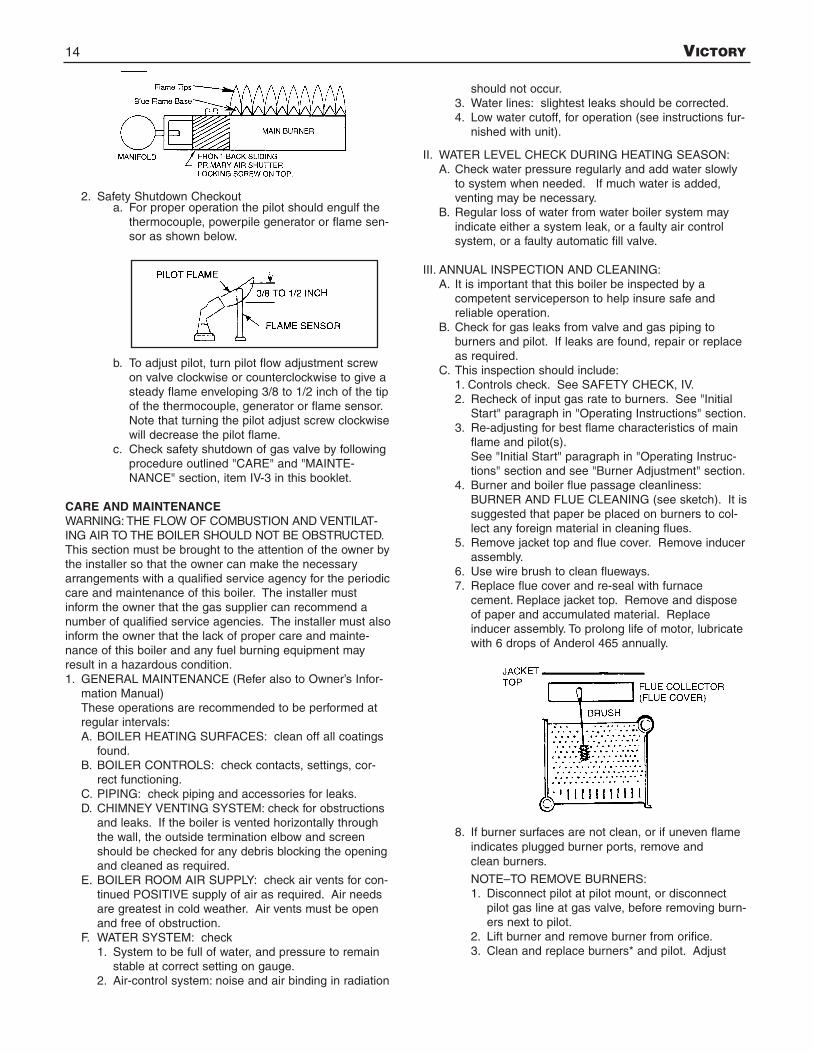
2. Safety Shutdown Checkouta. For proper operation the pilot should engulf the
thermocouple, powerpile generator or flame sen-sor as shown below.
b. To adjust pilot, turn pilot flow adjustment screwon valve clockwise or counterclockwise to give asteady flame enveloping 3/8 to 1/2 inch of the tipof the thermocouple, generator or flame sensor.Note that turning the pilot adjust screw clockwisewill decrease the pilot flame.
c. Check safety shutdown of gas valve by followingprocedure outlined "CARE" and "MAINTE-NANCE" section, item IV-3 in this booklet.
CARE AND MAINTENANCEWARNING: THE FLOW OF COMBUSTION AND VENTILAT-ING AIR TO THE BOILER SHOULD NOT BE OBSTRUCTED.This section must be brought to the attention of the owner bythe installer so that the owner can make the necessaryarrangements with a qualified service agency for the periodiccare and maintenance of this boiler. The installer mustinform the owner that the gas supplier can recommend anumber of qualified service agencies. The installer must alsoinform the owner that the lack of proper care and mainte-nance of this boiler and any fuel burning equipment mayresult in a hazardous condition.1. GENERAL MAINTENANCE (Refer also to Owner’s Infor-
mation Manual)These operations are recommended to be performed atregular intervals:A. BOILER HEATING SURFACES: clean off all coatings
found.B. BOILER CONTROLS: check contacts, settings, cor-
rect functioning.C. PIPING: check piping and accessories for leaks.D. CHIMNEY VENTING SYSTEM: check for obstructions
and leaks. If the boiler is vented horizontally throughthe wall, the outside termination elbow and screenshould be checked for any debris blocking the openingand cleaned as required.
E. BOILER ROOM AIR SUPPLY: check air vents for con-tinued POSITIVE supply of air as required. Air needsare greatest in cold weather. Air vents must be openand free of obstruction.
F. WATER SYSTEM: check1. System to be full of water, and pressure to remain
stable at correct setting on gauge.2. Air-control system: noise and air binding in radiation
should not occur.3. Water lines: slightest leaks should be corrected.4. Low water cutoff, for operation (see instructions fur-
nished with unit).
II. WATER LEVEL CHECK DURING HEATING SEASON:A. Check water pressure regularly and add water slowly
to system when needed. If much water is added,venting may be necessary.
B. Regular loss of water from water boiler system mayindicate either a system leak, or a faulty air controlsystem, or a faulty automatic fill valve.
III. ANNUAL INSPECTION AND CLEANING:A. It is important that this boiler be inspected by a
competent serviceperson to help insure safe andreliable operation.
B. Check for gas leaks from valve and gas piping toburners and pilot. If leaks are found, repair or replaceas required.
C. This inspection should include:1. Controls check. See SAFETY CHECK, IV.2. Recheck of input gas rate to burners. See "Initial
Start" paragraph in "Operating Instructions" section.3. Re-adjusting for best flame characteristics of main
flame and pilot(s).See "Initial Start" paragraph in "Operating Instruc-tions" section and see "Burner Adjustment" section.
4. Burner and boiler flue passage cleanliness:BURNER AND FLUE CLEANING (see sketch). It issuggested that paper be placed on burners to col-lect any foreign material in cleaning flues.
5. Remove jacket top and flue cover. Remove inducerassembly.
6. Use wire brush to clean flueways.7. Replace flue cover and re-seal with furnace
cement. Replace jacket top. Remove and disposeof paper and accumulated material. Replaceinducer assembly. To prolong life of motor, lubricatewith 6 drops of Anderol 465 annually.
8. If burner surfaces are not clean, or if uneven flameindicates plugged burner ports, remove andclean burners.
NOTE–TO REMOVE BURNERS:1. Disconnect pilot at pilot mount, or disconnect
pilot gas line at gas valve, before removing burn-ers next to pilot.
2. Lift burner and remove burner from orifice.3. Clean and replace burners* and pilot. Adjust

VICTORY 15
burners as described on page 13.*To clean burners run a clean flue brush up the tubeuntil all foreign matter is removed.
IV. SAFETY CHECK FOR CONTROL SYSTEM1. Remove Control Cover
To remove control cover, remove the two sheet metalscrews in the top of the top cover. (See figure 13.) Tiltcomplete control cover away from boiler and lift up until itclears the bottom angle bracket. To replace the cover,reverse procedure. Be sure that the tab on the bottom ofthe cover body enters the slot in the bottom angle bracket.CAUTION: The boiler should not be operated with coveroff except during certain control checkouts.
2. High Limit Control TestSet thermostat high enough for boiler water temperatureto reach high limit control setting. When this temperatureis reached, the high limit switch should open and themain gas valve should close automatically. If the highlimit does not operate to close the main gas valve, thevalve, the high limit or the wiring is faulty. Repair orreplace immediately.
3. Gas Valve Safety Shutdown TestFor boilers equipped with Honeywell S8600 intermittentpilot systems, with main burners firing, disconnect theignition cable from the S8600 IGNITOR BOX. The gasvalve should shut off the main burners.If the gas valve fails to shut off the main burners whenthe test is performed, replace the gas valve.
4. Air Flow Pressure Switch CheckWith the main burners firing, remove hose from pressureswitch, the one toward front of boiler, see figure 14.(Model V-180 has a single sensing hose.) Gas valveshould shut off the main burners.If the main burners do not shut down, shut off the powerto the boiler and check for continuity across the pressureswitch contacts. If the switch is made when the induceris not running, replace the pressure switch with one withthe exact model number as the existing switch.If the switch is open and burners do not shut off, replacethe ignition control or gas valve.
5. Check for gas leaks from valve and gas piping to burnersand pilot. If leaks are found, repair or replace asrequired.
V. 1. Providing Protection from FreezingAnti-freeze is sometimes used in hydronic heating sys-tems to protect against freeze-up in the event of powerfailure or control shutdown when the building is unoc-cupied. It should be recognized that unless the build-ing is kept above freezing temperature by somemeans, the plumbing system is not protected.Two types of anti-freeze may be used: ETHYLENEGLYCOL, used in automobiles, has desirable proper-ties, but is toxic. Its use may be prohibited when sys-tem water/glycol solution is in contact with a potablewater vessel (as with a tankless heater). PROPYLENEGLYCOL is used in the quick-freeze food industry; it ispractically non-toxic. Its use may be permitted whentankless heaters are used. When anti-freeze must beused, inhibited propylene glycol is recommended.Useful information on the characteristics, mixing pro-portions, etc. of glycol in heating systems is given inTechnical Topics No. 2A, available from the HydronicsInstitute, 34 Russo Place, Berkeley Heights, NJ 07922.Consult glycol manufacturers for sources of propyleneglycol.
2. Water TreatmentA good water treatment program will not only extendthe useful life of this boiler but it will also save much ofthe time and expense of repairs made necessary bypreventable occurrences.A reputable water treatment company should be con-sulted to evaluate and determine the best overall treat-ment program for your boiler equipment.
VI.KEEP THE BOILER AREA CLEAR AND FREE FROMCOMBUSTIBLE MATERIALS, GASOLINE, AND OTHERFLAMMABLE VAPORS AND LIQUIDS.
Figure 13.
Figure 14. Top View of Boiler
BOILER WATER CONTENT
Model Pounds Gallons
V-33 17.50 2.1V-60 24.75 3.0V-90 32.00 3.8V-120 39.25 4.7V-150 46.50 5.6
* For service remove ONLY these two screws. DO NOT remove anyother screws.

16 VICTORY
APPENDIX ARemoval Of Existing Boiler From Common Vent System
"At the time of removal of an existing boiler, the followingsteps shall be followed with each appliance remaining con-nected to the common venting system placed in operation,while the other appliances remaining connected to the com-mon venting system are not in operation."(a)Visually inspect the venting system for proper size and
horizontal pitch and determine there is no blockage orrestriction, leakage, corrosion and other deficiencieswhich could cause an unsafe condition.
(b) Insofar as is practical, close all building doors and win-dows and all doors between the space in which the appli-ances remaining connected to the common venting sys-tem are located and other spaces of the building. Turn onclothes dryers and any appliance not connected to thecommon venting system. Turn on any exhaust fans, suchas range hoods and bathroom exhausts, so they will oper-ate at maximum speed. DO NOT operate a summerexhaust fan. Close fireplace dampers.
(c) Place in operation the appliance being inspected. Followthe lighting instructions. Adjust thermostat so appliancewill operate continuously.
(d)Test for spillage at the draft hood relief opening after 5minutes of main burner operation. Use the flame of amatch or candle, or smoke from a cigarette, cigar or pipe.
(e)After it has been determined that each appliance remain-ing connected to the common venting system properlyvents when tested as outlined above, return doors, win-dows, exhaust fans, fireplace dampers and any other gas-burning appliance to their previous conditionsof use.
(f) Any improper operation of the common venting systemshould be corrected so the installation conforms with theNational Fuel Gas Code, ANSI Z223.1-latest edition.When resizing any portion of the common venting sys-tem, the common venting system should be resized toapproach the minimum size as determined using theappropriate tables in part 11 in the National Fuel GasCode, ANSI Z223.1-latest edition.
APPENDIX BVent System Location and Condensation
Drain Requirements
1. The venting system shall terminate at least 3 feet aboveany forced air inlet located within 10 feet.
2. The venting system shall terminate at least 4 feet below,4 feet horizontally from, or 1 foot above any door, windowor gravity air inlet into any building. The bottom of thevent terminal shall be at least 12 inches above gradeor the normal snow level, whichever is greater.
3. Through the wall vents for Category II and IV appliancesshall not terminate over public walkways or over areaswhere condensate or vapor could create a nuisance orhazard or could be detrimental to the operation of regula-tors, relief valves or other equipment. Minimum clearanceof 4' horizontally from, and in no case above or below,unless a 4' horizontal distance is maintained, from electricmeters, gas meters, regulators and relief equipment.Where local experience indicates that condensate may bea problem with Category I and III appliances, this provi-sion shall also apply.
4. Provision shall be made to collect and dispose of conden-sate from venting systems serving Category I, II, III andIV appliances.
CautionFlue gases exiting from the vent terminal will condense.Building materials in the area of the vent terminal should beprotected from discoloration and degradation.

VICTORY 17
Sequence of Operations Wiring Diagrams
CAUTION: Label all wires prior to disconnection when servicing controls.Wiring errors can cause improper and dangerous operation. “Verify properoperation after servicing.”
THERMOSTATCALLS FOR
HEAT
CIRCULATOR CONTINUES TORUN. NO FURTHER ACTION.
CIRCULATORCONTINUES TO RUN
INDUCER RELAY (2K)ENERGIZED. CONTACTS2K1 CLOSE. INDUCER
MOTOR RUNS.
L8148 RELAY (1K)CLOSES 1K1 AND 1K2
CONTACTS.CIRCULATOR RUNS.
IGNITION CONTROLENERGIZED.
SPARK GENERATOR OFF.SECOND VALVE OPERATOR
(MAIN) OPENS.MODULE MONITORS PILOT
FLAME.
SPARK GENERATOR POWERED.FIRST VALVE (PILOT) OPERATOR
OPENS.
THERMOSTAT SATISFIED.VALVES CLOSE PILOT AND
MAIN BURNERS OFF.INDUCER AND CIRCULATOR
OFF.
NATURAL GAS (S8600F)IGNITION SPARK CONTINUES.PILOT VALVE REMAINS OPEN
UNTIL SYSTEM RESET.CIRCULATOR AND INDUCER
CONTINUE TO RUN.
L.P. GAS (S8600M)IGNITION TRIAL CONTINUES
FOR 90 SEC. AFTER TRIAL FORIGNITION, SYSTEM SHUTS OFF.AFTER 5 MIN., MODULE REIN-STATES TRIAL FOR IGNITION.
NO
NO
CIRCULATOR AND INDUCERCONTINUE TO RUN.
NO FURTHER ACTION
NO
YES
YES
YES
NO
YES
HIGHLIMIT
CONTACTSCLOSED?
HIGHLIMIT
CLOSED?
AIRPROVING
SWITCH CON-TACTS
CLOSED?
PILOTFLAMEESTAB-
LISHED?
18 VICTORY
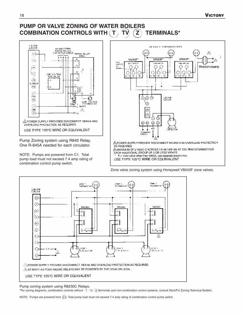
PUMP OR VALVE ZONING OF WATER BOILERSCOMBINATION CONTROLS WITH T TV Z TERMINALS*
Pump Zoning system using R845 Relay.One R-845A needed for each circulator.
NOTE: Pumps are powered from C1. Totalpump load must not exceed 7.4 amp rating ofcombination control pump switch.
Zone valve zoning system using Honeywell V8043F zone valves.
Pump zoning system using R8230C Relays.*For zoning diagrams, combination controls without T TV Z terminals and non-combination control systems, consult Slant/Fin Zoning Technical Bulletin.
NOTE: Pumps are powered from C1 . Total pump load must not exceed 7.4 amp rating of combination control pump switch.

VICTORY 19
BURNERS FAIL TO OPERATECAUSE1. Safety pilot out, or flame too low.2. Gas supply valve shut off.3. Electric switch open.4. Blown or defective line fuse.5. Operating or limit control contacts open or dirty.6. Defective gas valve or pressure regulator; or plugged bleed
line.7. Defective low voltage transformer of aquastat relay.8. Obstruction at main burner orifice.9. Break in wiring or loose contact at control terminals.
10. Improper wiring.11. Improper controls.12. Defective air flow pressure switch.13. Rollout switch open.
BURNERS WILL NOT SHUT OFFCAUSE1. Defective operating control, gas valve, or high limit control.2. Improper wiring or short circuit.
FLASH BACK - BURNING AT ORIFICESCAUSE1. Manifold gas pressure too low.2. Improper primary air adjustment.3. Gas regulator bleed too slow.4. Burrs on orifice.5. Improperly drilled orifice plugs.6. Leaking automatic gas valve.7. Adverse draft condition in boiler room.8. Low main gas pressure.9. Safety pilot improperly installed.
DELAYED IGNITIONCAUSE1. Pilot flame too low.2. Pilot burner ports or pilot orifice clogged.3. Burners or orifices out of alignment.4. Excessive primary air.5. Excessive burner input.6. Adverse draft condition in boiler room.
FUMES AND GAS ODORSCAUSE1. Leaks in gas piping or accessories.2. Gas leaks in service line or meter connections.3. Blocked chimney.4. Boiler flueways blocked with soot.5. Undersized breeching or too many turns in breeching.6. Adverse draft condition in boiler room.7. Overfiring.
CONDENSATION IN BOILER FLUES OR IN VENT SYSTEMCAUSE1. Underfiring.2. Boiler water maintained at too low a temperature level.
BURNER SHORT CYCLESCAUSE1. Thermostat heat anticipator set too high.2. Excessive pressure drop in venting system.3. Blockage or restriction in venting system.4. Faulty air flow proving mechanism.
REMEDY1. Check, clean, re-light. See instructions.2. Open gas valve(s).3. Close switch.4. Replace fuse.5. Check control. Clean contacts or replace control.6. Repair or replace.7. Replace aquastat.8. Check, clean and reinstall.9. Check with test-light and correct.
10. Check and correct in accordance with wiring diagramsincluded with appliance instructions.
11. Install proper controls.12. Check and replace if necessary.13. Replace rollout switch (inspect flue passages prior to
replacement).
REMEDY1. Check, repair or replace.2. Check wiring and controls.
REMEDY1. Adjust to proper manifold pressure.2. Adjust air to produce soft, clean flame.3. Adjust bleed opening.4. Remove burrs.5. Install orifice plugs with proper drilling.6. Repair or replace.7. Check air supply and venting system.8. Contact utility.9. Correct to manufacturer's recommendations.
REMEDY1. Increase gas supply to pilot.2. Clean ports or orifices.3. Realign burners or manifold.4. Adjust primary air shutters.5. Check and reduce to input shown on rating plate.6. Check air supply and venting system.
REMEDY1. Locate leaks and repair.2. Close service supply valve - shut down appliance and
notify utility.3. Check and repair chimney.4. Clean flueways and adjust burners as described in the
installation instructions.5. Check manufacturer's recommendations.6. Check air supply and venting system.7. Adjust gas input to that shown on boiler rating plate.
REMEDY1. Increase firing rate to that shown on rating plate.2. Set low limit controls to maintain a higher water tempera-
ture. If boiler is not equipped with low limit replace withone which has a combination low limit/high limit aquastat.
REMEDY1. Reset anticipator to *amps.2. Reroute and/or shorten venting system.3. Check for blockage or restriction.4. Consult factory.
GENERAL TROUBLESHOOTING GUIDE FOR SERVICEPEOPLE
*L8124=.20 amps, L8148=.20 amps, R845A=.40 amps

20 VICTORY
PIPING A HEATING - COOLING SYSTEM TO A WATERBOILER AND CHILLER
Figure below illustrates a method of piping a heating-coolingsystem to a water boiler and a chiller. Hand valves (shown) orautomatic valves must be installed to prevent circulation ofchilled water in the boiler or hot water in the chiller.
The air control system and pressure control system must
operate with chiller only, or the boiler only, being valved to thepiping system. Separate control devices on the boiler andchiller may be used, or a single set of air and pressure con-trols on the common piping may be preferred.
If the boiler is used to supply hot water to heating coils in airhandling units, flow control valves or other devices must beinstalled to prevent gravity circulation of water in the coils dur-ing the cooling cycle.
IF REPLACEMENT PARTS ARE NEEDED
When parts are needed, refer to boiler model and serial numbershown on the boiler name/rating plate. Refer to publication num-ber V-10PL Victory Replacement Parts for part numbers. When-ever possible refer to the original order by numberand date.
Control identification and replacement should not be attemptedby unskilled personnel. Only simple, easily-identified controls
and parts may be obtained locally. All other controls and partsshould be identified by and ordered from Slant/Fin. Relief/Safetyvalves must be ASME rated for the pressure and gross output ofthe boiler.
Replacement parts are available from:
Slant/Fin Corp.100 Forest DriveGreenvale, NY 11548
SLANT/FIN CORPORATION, Greenvale, N.Y. 11548 • Phone: (516) 484-2600FAX: (516) 484-5921 • Canada: Slant/Fin LTD/LTEE, Mississauga, Ontario
www.slantfin.com