Embed Size (px)
Citation preview

Vibration Characteristics of FGM Circular
Cylindrical Shells Containing Fluid
By
ZAFAR IQBAL
REGISTRATION NO: UOS/MATH/PhD/05/02
Department of Mathematics
University of Sargodha,
Sargodha, Pakistan
December, 2011

Vibration Characteristics of FGM Circular
Cylindrical Shells Containing Fluid
A Thesis Submitted to the Department of Mathematics, University of Sargodha in
candidature of the degree of
DOCTOR OF PHILOSOPHY
IN
Mathematics
Supervised By
Prof. Dr. Nazra Sultana
&
Dr. Muhammad Nawaz Naeem
Department of Mathematics, University of Sargodha,
Sargodha, Pakistan
December, 2011

CERTIFICATE
VIBRATIONS CHARACTERISTICS OF
FGM CIRCULAR CYLINDRICAL SHELLS
CONTAINING FLUID
A thesis submitted in the partial fulfillment of the requirements for the
degree of doctor of philosophy in Mathematics
By
ZAFAR IQBAL
We accept this thesis as confirming to the required standard.
1. 2.
Prof. Dr. Nazra Sultana Dr. Muhammad Nawaz Naeem
(Supervisor/Chairperson) (Supervisor)
3.___________________________
Prof. Dr. Muhammad Ozair Ahmed
(External)
Department of Mathematics
University of Sargodha, Sargodha, Pakistan
2011

DEDICATED TO
THE HOLY PROPHET (Peace be upon Him)
THE GREATEST SOCIAL REFORMER
TO
MY BELOVED
PARENTS
WHO TAUGHT ME
THE FIRST WORD TO SPEAK,
THE FIRST ALPHABET TO WRITE
AND FIRST STEP TO TAKE.
&
HONOURABLE TEACHERS

i
Acknowledgement
First of all I want to thank the Almighty ALLAH, the Most Merciful and the Most
Benevolent, who has given me ability to complete the requirements of this dissertation.
Special homage to the Holly Prophet Hazrat MUHAMMAD (Peace Be Upon Him),
who is the real source of knowledge, wisdom and guidance to the mankind. I am very
grateful to my worthy supervisors Professor Dr. Nazra Sultana and Dr. Muhammad
Nawaz Naeem for their untiring efforts, guidance, encouragement, intellectual
suggestions, cooperation and constructive criticism. Special thanks are extended to Dr.
Muhammad Nawaz Naeem for his constant guidance, encouraging discussions,
sharing new ideas, his insightful thoughts and patience over my ignorance. His
grasp of the subject, devotion and commitment toward his duties always inspired me
and provided me confidence to learn more and more and to try again and again for the
achievement of goal. I am also appreciative to my teacher Syed Gul Shah for his special
guidance and encouragement. I am highly obliged to the Higher Education Commission,
Islamabad, Pakistan, that made possible, the completion of this project by granting me
fellowship. I would never be able to finish this thesis without the prayers,
encouragement and help of my teachers, parents, my children, friends and colleagues to
whom I am very indebted. I am also thankful to all of my research fellows, especially
Shahid Hussain Arshad and Abdul Ghafar Shah and Sultan Mubariz for their company,
help and invaluable suggestions during my studies at the University of Sargodha. At
last but not the least I thank my all friends and well-wishers whose prayers are always
with me in accomplishing this project.
December, 2011 ZAFAR IQBAL

ii
Summary
The study of vibration characteristics of thin circular cylindrical shells is indeed a
very important area of research in the field of structural dynamics and the
applications of functionally graded materials (FGMs) are increasing day by day in
engineering, material science and sensitive modern technology. The vibration
characteristics of functionally graded material circular cylindrical shells containing
fluid are analyzed in this thesis.
Generally functionally graded materials are fabricated by metal and ceramic. In the
present study stainless steel, nickel and zirconia are utilized to structure the FGM
cylindrical shell. In this way three types of shells are obtained. Material properties of
the cylindrical shells vary continuously, smoothly and gradually from inner surface to
the outer surface of the FGM layer through the thickness of the shell. At the inner
surface of the FGM layer, one of the constituents is taken to be pure while the other
has zero concentration and a variation of the material properties of the FGM
constituents is carried out in the radial direction by applying a certain volume fraction
law till the first material get zero concentration and the second material acquire its
pure form for the fabrication of FGM cylindrical shell. Material distribution of the
FGM constituents is controlled by power law exponent of the volume fraction law.
Moreover natural frequencies of functionally graded material cylindrical shells
containing fluid are also studied and coupled frequencies and uncoupled frequencies
of shells are compared. Love's thin shell theory based on Kirchhoff's assumptions is
applied for strain-displacement and curvature-displacement relationships for deriving
governing dynamical equilibrium equations of cylindrical shells. To solve these
iii
equations, well-known numerical technique, the wave propagation approach, is
utilized by extremizing the Lagrangian energy functional to obtain the shell frequency
equation in the form of eigenvalue problem. This approach is very simple to apply
and give the accurate and precise results. Variations of the frequency spectra of
shells structured from functionally graded materials without fluid and containing fluid
are analyzed under different set of geometrical and material parameters and by the
variation of power law exponents for different boundary conditions such as simply
supported –simply supported, clamped-simply supported and clamped- clamped
boundary conditions. Similarly a comparison of the natural frequencies of the FGM
cylindrical shells is made with FGM cylindrical shells containing fluid.

iv
Layout of Thesis
Chapter 1 gives a brief introduction and preliminaries about vibration, shells. It also
presents short introduction about functionally graded materials (FGMs), their
existence in nature, history, scope, applications, their fabrication and classification.
In chapter 2 the introduction of the present method is given. Here the
importance and main feature of the present technique wave propagation are stated in
detail.
In chapter 3 the mathematical formulation of the FGM circular cylindrical shells
without fluid and containing fluid is given. The Hamilton’s principle is utilized to
derive the dynamic shell equations for the FGM circular cylindrical shells. The wave
propagaton approach is used to formulate the generalized eighenvalue problem which
then is solved by using MATLAB software.
In chapter 4 results obtained for the FGM circular cylindrical shells for six types
of shells for different boundary conditions are analyzed and are compared with those
results available in the literature. The effect of boundary condition is also discussed
here. The effect of geometrical parameter on frequency spectrum is also analyzed and
discussed for various boundary conditions.
In chapter 5 the Vibrational behavior of circular cylindrical shell made of FGMs
containing fluid for various boundary conditions are presented. The results obtained for
isotropic cylindrical shells are compared with those available in the literature. The
validity of present method wave propagation is proved by the results. The coupled and
uncoupled frequencies of FGMs circular cylindrical shells are compared and the

v
influence of the fluid on the frequency of the FG shells is studied here and results are
analyzed in detail. It also includes the concluding remarks.

vi
Notation
FGM Functionally Graded Materials
A11 , A12 , A22 Extensional stiffnesses
B11 , B12 , B22 Coupling stiffnesses
LC Sound speed of the shell
fC Speed of fluid respectively
D11 , D12 , D22 Bending stiffnesses
e11, e22 , e12 Mid-surface strain components
E Young’s modulus
F Lagrangian functional
h Shell thickness
( )n
J The Bessel function of order n
k11 , k22 , k12 Surface curvature components
K Kinetic energy
L Length of the shell
m Axial wave number
xM , Mθ ,
xM θ The moment resultants.
xN , Nθ ,
xN θ Force resultants
n Circumferential wave number
N Power law exponent
P Property of the constituent material

vii
Qi,j Reduced stiffnesses
R Shell mean radius
S Strain energy
t Time
TK Temperature in Kelvin
u, v, w Axial, circumferential and radial deformation
components of the shell mid surface
Vf Volume fraction of constituent material
x Axial coordinate
x, , z Components of orthogonal coordinate system
n Circumferential wave number
N Power law exponent
P Property of the constituent material
Qi,j Reduced stiffnesses
ρ Mass density
v Poisson’s Ratio

Table of Contents
Acknowledgment i
Abstract ii
Nomenclature iii
Lay out of thesis iv
Notation vi
1 INTRODUCTION 1
Literature review
1.1 Functionally Graded Material (Definition)…………………………………… 1
1.2 Functionally Graded Material in nature………………………………………… 4
1.3 Fabrication of Functionally Graded Material ………………………………….. 4
1.4 Thermal Protection ………………………………………………………….. 5
1.5 Advantages of Functionally Graded Materials………………………………… 6
1.6 Applications…………………………………………………………………… 6
1.7 Shell ………………………………………………………………………… 7
1.8 Vibration of cylindrical shell ………………………………………………… 8
1.9 Vibration of FGM circular cylindrical shells ………………………………… 9
1.10 Motivation and objective of the present work ……………………………….. 13
2. MATHEMATICAL FORMULATION 15
2.1 Functionally graded materials ………………………………………………… 15
2.2 Volume fraction ……………………………………………………………… 17
2.3 Theoretical Formulation ………………………………………………………. 18
2.4 Strain - Displacement and Curvature- Displacement Relations……………… 22
2.5 Derivation of shell dynamical equation……………………………………... 24

3 NUMERICAL METHODOLOGY 27
3.1 Solution Procedure ………………………………………………………… 30
3.2 The fluid filled in the FGM cylindrical shell……………………………….. 31
3.3 Bessel Functions…………………………………………………………… 32
4. Numerical Results for the Vibration of FGMs Circular Cylindrical Shell 35
4.1 Comparison of the results ………………………………………………….. 35
4.2 Isotropic circular cylindrical shells…………………………………………. 35
4.3 Comparison of results for FGMs circular cylindrical shells………………… 36
4.4 Conclusion about the present method ………………………………………. 37
4.5 Numerical result for FGM circular cylindrical shells …………………….. 37
4.6 Effect of Volume fraction ………………………………………………… 38
4.7 Frequency analysis for of FGM circular cylindrical shells ……………….. 39
4.8 The Effect of ratios on frequencies of FGM cylindrical shell……………….. 41
4.9 The variation of resultant material properties ………………………………. 42
5. Numerical Results for the Vibration of FGM Circular Cylindrical Shells Containing Fluid
5.1 Comparison of the results……………………………………………………. 43
5.2 Comparison of coupled and uncoupled frequencies of the FGMs shells ……. 44
5.3 CONCLUDING REMARKS ………………………………………………… 49
6. BIBLIOGRAPHY 51
7. Tables 60
8. Figures 93
9. Appendix A 112
10. Appendix B 113
10. Publish work 114

1
CHAPTER 1
Introduction
Literature review
1.1 Functionally Graded Material
Functionally graded materials (FGMs) are planned to achieve levels of higher
performance than that of homogeneous materials by combining the wanted properties
of each constituent segment. They are multi-functional materials in which the
composition or the microstructure is locally changed to obtain the certain variation of
local material properties. Functionally graded structures are new for scientists but not
for nature. FGMs are present in the nature in the form of tissues of animals, such as
bones and teeth, and also in plants e.g. Bamboo.
Functionally graded materials have ability to show excellent performance in a very high
temperature environment. Recent studies on these materials divulge that they are
appropriate for structures exposed to non-uniform service conditions and under high
thermal atmosphere. Ceramics and metals’ mixture is used to structure these
microscopically heterogeneous materials.
The concept of a new generation of composites of microscopically heterogeneity and
the ability to make them, emerges to be a modern wonder of engineering innovation in
the early 1980s [1, 2]. During the fabrication of functionally graded materials the
porosity, microstructure, volume fraction of the components materials are controlled
and resulted as a special class of materials at larger scale of structures related with
mechanical and heat properties. Consequently they are better than the conventional
composite laminates because of having lesser thermal stresses, intensity factors or
stress concentrations and decrease of stress waves. They keep their structures intact in a

2
high temperature environment as in heat exchanger tubes, spacecraft heat shields,
biomedical implants, flywheels, engine components, plasma facings for fusion reactors,
and high power electrical contacts or even magnets. With their extensive applications in
modern industries and the intrinsic nature of FGMs as thermal blockade materials,
many researchers mainly paid attention on their thermo-mechanical performance. From
the beginning of recent century [3-6] their thermo-mechanical behavior made them
such important that they have earned continuous and more massive attention.
Many scientists explained the pure elastic behavior of FGMs such as the bending
because of mechanical loads, buckling and free vibration stability etc., for engineering
design and manufacture it is very important to have a deep understanding about all
these properties and behavior.
Tanigawa [7] performed a complete analysis of analytical models of thermo-elastic
action of FGMs. Suresh and Mortensen [8] gave an overview of the fundamentals of
thermo-elastic/plastic deformation in metal–ceramic composites. They also gave the
review of the some existing approaches such as the regulation of mixture
approximations, crystal plasticity models, average field global theories, discrete
dislocation models and the formulation of the constitutive phases.
Change in composition, porosity, microstructure etc is produced due to the difference
of constituent volume fraction of functionally graded material and this consequences in
gradient in the thermal and mechanical properties and as a result to get overall
improved performance. Ceramics and metals’ mixture is used to structure these
materials. Being multifunctional materials they have ability to coalesce the desired high
temperature properties and thermal resistance of a ceramic with the metal having
fracture stiffness and strength. The stiffness of a metal can be combined with the
refractoriness of ceramic to utilize the properties of the both constituent materials. The

3
high temperature resistance is provided by the ceramic component while the fracture
caused by high stress is averted by metal of the functionally graded materials.
The idea of FGM is not new, although the concept of functionally graded materials, and
the ability to make them, emerges to be a modern wonder of engineering innovation.
The Japanese material scientist [1, 2] introduced the concept of functionally graded
materials in the form of planned thermal barrier material have capacity of bearing a
surface temperature of 2,000K and a temperature gradient of 1,000K across a cross
section less than 10mm while working on the space plane project in 1984. Since then
extensive research has been done on FGM thin film, making it a commercial reality.
The properties of material changes continuously from one surface to another surface in
a group of composite, the functionally graded material and the stress concentration is
reduced in laminated composites. Thermal stresses, residual stresses, and stress
concentrations is reduced by the gradation in the material properties. The volume
fractions of two or more materials change gradually as a function of position in the
particular direction of the structure in functionally graded material to obtain a desire
functional optimality. Variation in the properties throughout the dimension of material
FGM can provide designers with adapted material response and excellent performance
in thermal atmosphere. For example, the ceramic tiles are utilized in Space Shuttles for
protection from the heat produced at the time of re-entry into the Earth’s atmosphere.
The vehicle’s superstructures are laminated by these tiles having tendency to crake at
the superstructure/tile interface because of sudden transition between thermal
coefficients. The ceramic tiles have different rate of expansion as compared to the
substructure it is protecting. The phenomenon brings about the stress concentration at
the boundary of the tiles and superstructure which consequences in cracking.
4
1.2 Functionally Graded Materials in Nature
Although the idea of functionally graded materials, and the ability to fabricate them,
appears to be a modern wonder of engineering innovation, the concept is not new. They
have been in use by nature for eons. Natural fibers are available in large quantity in
tropical and subtropical regions of the world and due to low cost are capable for
engineering applications and can be utilized as a construction material. Among natural
fibers, use of bamboo is in vogue for the construction of houses in the majority of the
world areas. Bamboo reveals the concept of Functionally Graded Material in optimized
form. Like others Biological structures bamboo has complicated micro structural
shapes and material distribution. Bamboo is an exceptional representative, where the
microstructure consists of a spatially varying concentration of voids and pores in order
to maximize bending rigidity, and bending power, while minimizing mass. Bone has
similar functional grading; while even human skin is graded to offer certain roughness,
tactile and elastic qualities as a function of skin depth and location on the body.
1.3 Fabrication of Functionally Graded Material
Functionally graded materials have been getting popularity in engineering fields,
because of their application in a high temperature environment. They are utilized in
many engineering fields, especially in nuclear reactors, heat exchanger tubes, plasma
facings for fusion reactors, spacecraft heat shields, engine components, high power
electrical contacts and chemical plants. The mechanical properties change easily and
continuously in a functionally graded materials from one surface to the other.
Continuous variations in the volume fractions of constituent materials create change in
the composition of functionally graded materials. Superior oxidation and thermal shock
resistance is provided by functionally graded material and powder metallurgy technique

5
is used to structure them by mixture of two or more materials. In engineering
applications it has great importance that the material properties of constituent materials
and microstructure can be tailored so that it can protect against potential failure.
Functionally graded materials are used as a wear resistant layer in the parts of machine
and engine and help to reduce the residual and thermal stresses in bonded different
materials by improving the bonding strength of layered composites. They can be graded
uniformly to a transition from an inner metallic surface to outer ceramic surface. Inner
metallic surface provides stiffness and outer ceramic surface protect from heat. In
current years, functionally graded materials have created rooms for discussion and
research because of their practical application in engineering fields. Such types of
materials are fabricated by mixing ceramic and metals. At high level temperature, the
thermal resistance property of ceramic are combined with the fracture strength and
hardness of a metal in a FGM. To utilize the properties of the both constituent materials
the stiffness of a metal can be combined with the refractoriness of ceramic. The high
temperature resistance is provided by the ceramic constituent material while the metal
part averts the fracture caused by high stresses. They can be made by powder
metallurgy techniques and some others methods have been performed to find out the
material properties of FGMs.
1.4 Thermal Protection
Functionally graded materials are highly developed material and have special
mechanical and heat resistant material properties. Ceramic and metals are used to
manufacture them. The high temperature resistance is provided by the ceramic
component on outer surface while the fracture caused by high stress is averted by metal

6
on inner surface of the functionally graded materials. Material composition of FGMs
varies gradually through-the-thickness. They reduce the stress concentrations.
1.5 Advantages of Functionally Graded Materials
The best distribution of stresses
• Optimal division of crack initiation sites
• Delaying the onset of damage and yielding
• Improve the interfacial bond potency
• Minimizing or eliminating edge effects and singular fields at corners
• Deposit thick surface coatings (up to 2 mm)
• Improve the action at high temperature by reducing thermal stresses control of
surface smash up and cracking during groove, shock and penetration.
1.6 Applications
Functionally graded materials provide a solution for many highly developed
applications, where two or many kinds of materials with different properties are
required to be integrated together. Therefore, FGMs have got interest and have been
applied in a broad range of applications, such as navigation industry, nuclear power
source, electrical material, chemical industry. They are used in high temperature
surroundings because they maintain their integrity. During the last two decades, FGMs
have highly advance applications in electronics, nuclear, biomedical, optics, chemical,
aerospace, mechanical and civil engineering. Due to the intrinsic nature as a thermal
barrier and engineering application of FGM many researchers were attracted and their
research were mainly concentrated on thermo-mechanical performance. Therefore,

7
these materials are used where temperature is very high as in spacecraft heat shields,
heat exchanger tubes, biomedical implants, flywheels, plasma facings for fusion
reactors, engine components, and high power electrical contacts or even magnets. For
being continuous variation in material properties in macroscopic structure these
materials are preferable to conventional fiber-matrix materials in mechanical behavior,
particularly their uses in high temperature atmosphere. Now FGMs can also offer
designers with tailored material response and excellent performance in high
temperature situation. Ceramic tiles are utilized in a space shuttle as a heat barrier
against the heat created in the process of returning into the earth’s orbit. However the
superstructures of a space vehicle are laminated by these tiles and have a tendency to
cracking at the superstructure on account of sudden transition between thermal
expansions coefficients. The ceramic tiles have different rate of expansion as compared
to the substructure it is protecting. The phenomenon brings about the stress
concentration at the boundary of the tiles and superstructure which results in cracking.
1.7 Shells
The word shell is very common in many fields of engineering due to its application.
This word is derived from the Latin “scalus” which mean scales of fish. The word shell
is frequently used in our daily life to illustrate the covering of the eggs, tortoise etc.
There is a great difference of rough but flexible scaly covering of a fish and the tough
but rigid shell of turtle. The word shell is usually used in various fields of engineering.
Shell structures have always been an interesting area of research. Their unpredictable
performance and difficulties in their mathematical as well as numerical modeling make
these structures a challenge for researchers and engineers. Since shells are found
abundantly in nature, it is not surprising that they have been extensively used as

8
efficient load-carrying members in many engineering structures. Shells can uphold
large loads with remarkably little material. Examples of shell applications include
roofs, lenses, storage tanks and helmets; they are also seen in aircraft, automobile and
off-shore structures. The structure of Shells is three-dimensional. Circular cylindrical
shells are of great interest for researchers among all existing shells models for being
simple geometrical configurations and having a lot of applications in the fields of
engineering and technology. They are utilized in engineering structure such as chimney
design, pipe flow, submarines, silos, pressure vessels, core-barrels of pressurized water
and nuclear reactors, aircraft fuselages, offshore pipelines etc.
1.8 Vibration of Cylindrical Shells
Vibration of Shells is much important in daily life and mostly used in the nature and
has widely application in the different branches of engineering. Vibration of shells has
also got a tremendous interest of researchers. Sophie Germaine has studied the problem
of thin cylindrical shell first in 1821. In 1888, Love has developed the thin wall shell
theory known as Love’s shell theory [9]. All others theories have been derived from
Love’s shell theory. Arnold and Warburton [10, 11] used the energy variational
method to study the vibration of circular cylindrical shells. Sewall, and Naumann [12]
studied the experimental and analytical vibration of this cylindrical shells with and
without longtituinal stiffeners by employing the energy Rayleigh-Ritz variational
approch. Sharma and Johns [13] theoretically analyzed the vibration of clamped-free
and clamped-stiffened shells by employing Flügge shell theory for a variety of choice
of axial modal shapes. Sharma [14] calculated the natural frequencies of fixed – free
circular cylindrical shells and a detailed analysis is given for the case of the axial mode
being approximated by characteristics beam functions with suitable end conditions.

9
Sharma [15] used the first order Sanders’ thin shell theory and studied the vibration
characteristics of thin circular cylindrical shells for a number of boundary conditions.
Blevins [16] gave a summary of work done on the shell vibrations and gave various
simple formulas for vibration characteristics. Different researchers employ different
numerical techniques to study the vibration characteristics of cylindrical shells. Loy et
al. [17] used the generalized differential quadrature method to study the vibration
frequency spectrum of shell for simply supported – simply supported, clamped-
clamped and clamped- simply supported boundary conditions. Joseph Callahan and
Haim Barugh [18] presented a systematic procedure for obtaining the closed-form
eigensloution for this circular cylindrical shell vibrations. The mode shapes and natural
frequencies determined analytically for an extensive variety of boundary conditions,
including elastics and rigid ring stiffeners at the boundaries.
1.9 Vibrations of FGM Circular Cylindrical Shells
Study of vibrations of circular cylindrical shells fabricated by functionally graded
materials is of much importance due to a variety of its uses in the industries. They are
promising materials and have capability to keep up their existence in a very highly
produced temperature situation. The shells constructed from such type of materials are
the fundamental elements in many engineering devices. Analytical study of the above
mentioned mechanical aspect i.e., shell vibration is important area of research prior to
shell structure use in industry, flight objects and marine crafts. This helps to govern the
future fatigues produced due to vibrations. The main aspects are to study the natural
frequencies an mode shapes which are main means of information for understanding
and controlling the vibration of these structures. A huge amount of research work has
done on FGM cylindrical shells.

10
In 1999, Loy et al. [19] first investigated the free vibration of simply supported FGM
cylindrical shells by employing the Rayleigh-Ritz method to evaluate natural
frequencies for a simply supported cylindrical shell. The axial modal dependence was
approximated by trigonometric functions. They observed that the frequency spectra are
dependent on volume fraction law and the configuration of the constituent materials in
FGM. This work was later extended by Pradhan et al. [20] to cylindrical shells under
various boundary supporting conditions. They did work on the vibration characteristics
of FGM cylindrical shell made of stainless steel and zirconia for a number of boundary
conditions. Han et al.[21] analyzed the transient waves in plates of functionally graded
materials. Han et al. [22] studied the characteristic of waves in cylindrical shell
composed of functionally graded material. They found that the ratio of radius to
thickness has a great impact on the shell frequencies with regards to the circumferential
wave as compared to the axial wave. Gong et al. [23] analyzed elastic response
analysis of simply supported FGM cylindrical shells under low-velocity impact. Ng et
al.[24] analyzed dynamic instability of simply supported FGM cylindrical shells; a
normal-mode expansion and Bolotin method were applied to find out the boundaries of
the unstable regions. Yang [25] took the creep into account and analyzed the stresses in
a joined FGM cylinder. Naeem and Sharma [26] predicted the natural frequencies for
thin circular cylindrical shells by employing the Rayleigh- Ritz variational approach.
In 2002, Naeem [27] worked on vibration analysis of non-rotating and rotating FGM
circular cylindrical shells using Rayleigh-Ritz method and Galerkin technique,
respectively. The characteristic beam functions for rotating ones and Ritz polynomial
functions for non-rotating shells approximate axial modal dependence, respectively.
Najafizadeh and Isvandzibaei [28] studied the vibration of thin cylindrical shell with
ring supports made of functionally graded material composed of stainless steel and

11
nickel. Their analysis is based on higher order shear deformation plate theory. Arshad
et al. [29] gave a frequency analysis of functionally graded material cylindrical shells
with various volume fraction laws. They explore the behavior of shell frequencies for a
number of physical parameters. Z Iqbal et al. [30] studied the vibration characteristics
of FGM circular cylindrical shells by employing the wave propagation approach and an
axial modal dependence is approximated by exponential functions. The variation of
frequencies with regard to the volume fraction laws studied. Shah et al. [31]
investigated the vibration of FGM thin cylindrical shells with exponential volume
fraction law by employing the Raleigh- Ritz to analyze the effect of volume fraction on
the frequencies of the thin cylindrical shells. Shah et al. [32] studied the vibration of
functionally graded cylindrical shells based on elastic foundation.
Study of vibration characteristics of functionally graded cylindrical shells filled with
fluid is of great importance and well-established field of research in structural
dynamics. Shells with fluid are used in many types of engineering structures such as
pressure vessels, oil tanker, aero planes, ships and marine crafts etc. In 1952, Junger
[33] first studied the coupled vibration of fluid- filled cylindrical shells. Jain [34] did
work to study the free vibration of an orthotropic cylindrical shell that is filled partially
or completely with an incompressible, non-viscous fluid. Goncalves and Batista [35]
analyzed the frequency response of cylindrical shells partially submerged or filled with
liquid. Lee et al. [36] gave a theoretical analysis of free vibration of vertical simply
supported cylindrical shells filled with liquid with ideal liquid has been investigated.
Amabili et al. [37] obtained the analytically the exact solution to the free vibration of
simply supported partially filled horizontal cylindrical shells with fluid. Amabili [38]
used the Donnell’s non-linear shallow shell theory to study the non-linear free and
forced vibrations of a simply supported circular cylindrical shell in contact with an

12
incompressible and no viscous quiescent dense fluid. He studied the non linear
dynamics and stability of circular cylindrical shell containing flowing fluid and large
amplitude vibration without fluid flow. Chen et al.[39] studied the exact solution of
free vibration of a transversely isotropic cylindrical shell filled with the fluid. Zhang et
al. [40] employed the wave propagation approach to study the coupled vibration
analysis of fluid - filled cylindrical shells. Zhang [41] extended the wave propagation
approach to coupled frequency of finite cylindrical shells submerged in a dense
acoustics medium and investigated the effect of parameters and boundary conditions on
coupled frequency of shells. Chen et al. [42] studied the three dimensional free
vibration of simply supported, fluid filled cylindrically orthoropic FGM cylindrical
shells with arbitrary thickness.
Lukovskii [43] used the variationaly approach to solving dynamics problems for fluid
containing bodies. Goncalves et al. [44] derived an accurate low dimensional model
based on Donnell’s shallow shell equations and applied for the study of the nonlinear
vibrations of an axially loaded fluid-filled circular cylindrical shell in transient and
permanent states. Koval’chuk et al [45] have investigated the frequency spectrum of
cylindrical shells of finite length filled with fluid and having ends either simply
supported or clamped. They examined the influence of the geometry of the shell and
fluid. Natsuki et al. [46] have presented a Vibrational analysis of fluid filled double-
walled carbon nanotubes using the wave propagation approach. They used Flugge shell
equations governing the vibration of the carbon nanotubes.
Haddadpour et al. [47] analyzed the free vibration of simply supported FG cylindrical
shells under thermal effects using four sets of in-plane boundary conditions. Sheng et
al. [48] investigated the vibration of functionally graded cylindrical shells with flowing
fluid. They used the first order shear deformation theory in order to model the dynamics

13
characteristics of FG cylindrical shell containing flowing fluid. Z.Iqbal et al.[49]
studied the vibration characteristics of FGM circular cylindrical shells filled fluid by
employing the wave propagation approach and compared the coupled frequencies and
uncoupled frequencies of the shells and the effected of fluid on shell frequency is
examined here for various boundary conditions.
1.10 Motivation and Objective of the Present Work
Study of vibration characteristics of functionally graded cylindrical shells is of great
importance and well-established field of research in structural dynamics. Shells are
used in many types of engineering structures such as pressure vessels, oil tanker, aero
planes, ships and marine crafts etc. The study of vibrations characteristics of thin
circular cylindrical shells is a significant field of research as they are extensively used
in industry, flight structures and marine crafts. A lot of research material is available in
literature related to the vibration of thin circular cylindrical shells fabricated by
functionally graded material. Different methods are employed to study the vibration
characteristics of FGM cylindrical shells. The most commonly used Rayeigh-Ritz
method is adopted by many researchers to solve the problems. In the present research
work the wave propagation approach is employed to study the Vibration behaviour of
FG circular cylindrical shells. Here the uncoupled and coupled frequencies of the shells
are analyzed and the influence of the fluid on the frequencies of circular cylindrical
shells is examined. In the present research work three constituent materials viz;
Stainless steel, Nickel and zirconia are used for constructing the different types of
shells. Six types of shells obtained by changing the order of the constituent material
from one to the other through the shell thickness. The vibration characteristics of
circular cylindrical shells structured from the FGMs without fluid and containing fluid

14
are studied. Love’s shell theory adopted for the study of the problem. The influences of
the fluid on the frequencies of the shells made of FGMs are analyzed here in detail. The
eigenvalue problem is solved for the natural frequencies and mode shapes by using the
powerful software package namely, MATLAB. Only one MATLAB program provides
the shell frequencies by changing the values of the axial wave number for a boundary
condition. This is the main feature of wave propagation approach that has been adapted
here. The uncoupled frequencies and coupled frequencies of vibrating are calculated for
a cylindrical shell for different boundary conditions and the results are compared with
those available in the literature for a check on the validity and efficiency of the
procedure adapted here. A very good agreement is found to exist between various
results.
In chapter 2 the introduction of the present method is given. Here the
importance and main feature of the present technique wave propagation are stated in
detail.
In chapter 3 the mathematical formulation of the FGM circular cylindrical shells
without fluid and containing fluid is given. The Hamilton’s principle is utilized to
derive the dynamic shell equations for the FGM circular cylindrical shells. The wave
propagaton approach is used to formulate the generalized eighenvalue problem which
then is solved by using MATLAB software.
In chapter 4 results obtained for the FGM circular cylindrical shells for six types
of shells for different boundary conditions are analyzed and are compared with those
results available in the literature. The effect of boundary condition is also discussed
here. The effect of geometrical parameter on frequency spectrum is also analyzed and
discussed for various boundary conditions.

15
In chapter 5 the Vibrational behavior of circular cylindrical shell made of FGMs
containing fluid for various boundary conditions are presented. The results obtained for
isotropic cylindrical shells are compared with those available in the literature. The
coupled and uncoupled frequencies of FGMs circular cylindrical shells are compared
and the influence of the fluid on the frequency of the FG shells is studied here and
results are analyzed in detail.

16
Chapter 2
MATHEMATICAL FORMULATION
This chapter deals with the mathematical formulation to study the vibration problem of
circular cylindrical shells structured from isotropic as well as functionally graded
materials.
2.1 Functionally Graded Materials
The functionally graded materials are promising material and have properties to
maintain their structure intact at very high temperature environment. They are highly
developed material and have special mechanical and heat resistant material properties.
Functionally graded materials have been getting popularity in engineering fields,
because of their application in a high temperature environment. They are utilized in
many engineering fields, especially in nuclear reactors, heat exchanger tubes, plasma
facings for fusion reactors, spacecraft heat shields, engine components, high power
electrical contacts and chemical plants. The mechanical properties in functionally
graded materials vary smoothly and gradually from one surface to other. The
continuous changes in volume fraction produced the variation in the composition of the
functionally graded material. They are structured by the mixture of two or more
materials by using powder metallurgy technique to provide superior oxidation and
thermal shock resistance.
In engineering application it is of great importance that the material properties of
constituent materials and microstructure can be tailored so that it can protect against
potential failure. Functionally graded materials are used as a wear resistant layer in the
parts of machine and engine and help to reduce the residual and thermal stresses in
bonded different materials by improving the bonding strength of layered composites.
They can be graded uniformly to a transition from an inner metallic surface to outer

17
ceramic surface. Inner metallic surface provides stiffness and outer ceramic surface
protect from heat. In current years, functionally graded materials have created rooms
for discussion and research because of their practical application in engineering fields.
Usually ceramic and metals are used for the fabrication of functionally graded
materials. They are multi-functional materials that combine the desirable high
temperature properties and thermal resistance of a ceramic with the fracture toughness
and strength of a metal. The toughness of a metal and refractoriness of ceramic can be
fully utilized in functionally graded materials. The ceramic component of the material
endow with the high temperature resistance while the metal part averts the breakage
caused by high stresses. They can be prepared by powder metallurgy techniques [50-
52] and some methods to determine the material properties of FGMs have been
performed as well [53, 54]. The circular cylindrical shells can be prepared from FGMs
and their vibration characteristics can be studied. The thermal resistance and high
temperature property of ceramic and the fracture toughness and strength of metal are
combined in a functionally graded material. The properties of both constituent
materials are combined together and can be fully utilized. For example, the
refractoriness of a ceramic mated with the toughness of a metal. So FGMs are used for
the fabrication of cylindrical shells and their influence on vibrations of these shells is
investigated. The circular cylindrical shell under consideration is composed of two
materials M1 and M2 is considered here to study its vibration characteristics. The
material properties of a component material of the shell depend upon temperature and
are expressed by the formula
1 2 3
0 1 1 2 3( 1 )P P P T P T P T P T−
−= + + + + (2.1)
where 0 1 1 2, , ,P P P P−
and 3P are the coefficients of temperature T(K) expressed
in Kelvin and are unique to the constituent materials.

18
2.2 Volume Fraction
The resultant particular material property P of a functionally graded material fabricated
from the k constituent materials can be expressed as
1
l
k f k
k
P P V=
=∑ (2.2)
where Pk and Vf k are respectively, represent the material properties and volume
fraction of the constituent material k. The sum of volume fractions of all the constituent
materials equals to unity, i.e,
1
1l
f k
k
V=
=∑ (2.3)
the middle surface is taken as reference surface for a cylindrical shell with uniform
thickness h, the volume fraction is described as
= .
(2.4)
where p denotes the power law index and is taken to be 0 p≤ ≤ ∞ and z represents the
thickness parameter measured from the reference surface. For a FGM cylindrical shell
structured from two materials M1 and M2, the resultant material properties i.e. the
Young’s modulus E, Poisson’s ratio v and the mass density ρ are given by
= − ℎ+0.5
+ (2.5)
= − ℎ+0.5
+ (2.6)
= − ℎ+0.5
+ (2.7)

19
From these expressions when z =-h/2, E=E1, v = v1, 1ρ ρ= and when z=h/2 , E =
E, v = v2, 2ρ ρ= . This shows that the material properties at the inner surface of the
shell correspond to the constituent material M1 and they are associated with the
constituent material M2 at the outer surface of the shell. A material property in a FGM
varies in the thickness direction. Thus for the present cylindrical shell the material
properties change gradually from material M1 at the inner surface to the material M2 at
the outer surface of the shell. The classical shell theories are applicable for FGM shell if
the thickness-to-radius ratio is less than 1/20. The FGM cylindrical shells are fabricated
from three types of materials viz., stainless steel, nickel and zirconia. Six types of FGM
circular cylindrical shells are supposed to be structured by changing the order of the
materials constituting the shell. Each shell is composed of two materials.
2.3 Theoretical Formulation.
The circular cylindrical shell having length L, radius R, and thickness h under
consideration for vibration study is shown in Fig.1. Young’s modulus E, Poisson’s ratio
v, and mass density ρ are the shell material parameters. An orthogonal coordinate system
with cylindrical coordinates (x, θ, z) taken at the middle surface of the shell. The
displacement deformations in axial, circumferential and radial direction are represented
by u, v and w respectively.
The force and moments resultants are defined as
/2
/2
( , , ) ( , , )
h
x x x x
h
N N N dzθ θ θ θσ σ σ−
= ∫ (2.8)
/2
/2
( , , ) ( , , )
h
x x x x
h
M M M zdzθ θ θ θσ σ σ−
= ∫ (2.9)

20
where , ,x xθ θσ σ σ are the normal stresses for a thin cylindrical shell in the x-direction,
ɵ- direction and x ɵ - direction is the shear stress respectively. According to the
Hooke’s Law “the stress is proportional to the strain provided the strain is small”
The relationship between stresses , ,x xθ θσ σ σ and strains , ,x xe e eθ θ is given by the
Hooke’s law [55, 56]
Q eσ = (2.10)
where σ is the stress vector, e is the strain vector and Q is the reduced stiffness
matrix. The stress and strain vector for shell are defined as
, ,T
x xθ θσ σ σ σ= (2.11)
and
, ,x x
e e e eθ θ= (2.12)
The reduced stiffnesses matrix is defined as
11 12
12 22
66
0
0
0 0
Q Q
Q Q Q
Q
=
(2.13)
where i j
Q ’s are reduced stiffness for a thin circular cylindrical shell and are
defined as:
11 22 21
EQ Q
v= =
− (2.14)
12 21
vEQ
v=
− (2.15)
662(1 )
EQ
v=
+ (2.16)

21
For a thin cylindrical shell the strain components , ,x x
e e eθ θ have been defined as
linear functions of the thickness coordinate z by the following relations:
1 1xe e zk= + (2.17)
2 2e e zkθ = + (2.18)
2x
e zθ γ τ= + (2.19)
xe , eθ denotes the strains in the axial and circumferential directions respectively and
xe θ the shear strain at a distance z from the reference surface.
1 2,e e and γ are the
reference surface strains and 1 2,k k and τ are the reference surface curvatures.
The expression for strain energy, S of a vibrating cylindrical shell is described by
[ ] [ ][ ]2
0 0
1.
2
LT
S T R d dx
π
ε ε θ= ∫ ∫ (2.20)
where
11 22 12 11 22 12, , , , , 2T
e e e k k kε = (2.21)
1 1 12 11 1 2
12 2 2 12 22
66 66
1 1 12 11 12
12 2 2 12 22
66 66
0 0
0 0
0 0 0 0[ ]
0 0
0 0
0 0 0 0
A A B B
A A B B
A BT
B B D D
B B D D
B D
=
(2.22)

22
and Aij, Bij, and Dij (i, j =1, 2 and 6) are the extensional, coupling and bending stiffness
respectively. The stiffnesses Aij, Bij, and Dij are defined as :
2
2
2
, , 1, , .
h
ij ij ij ij
h
A B D Q z z dz−
= ∫ (2.23)
where the coupling stiffnesses Bij, become zero for isotropic cylindrical shells and are
non-zero for FGM shells. The sign of Bij, for FGM depends upon the order of the
constituent materials in the FGM. They are positive for a configuration of a FGM and
become negative if the order of constituent materials is reversed.
The kinetic energy K of the cylindrical shell is expressed as:
2 2 22
0 0
1
2
L
T
u v wK Rd dx
t t t
π
ρ θ ∂ ∂ ∂
= + + ∂ ∂ ∂
∫ ∫
(2.24)
at any time t and T
ρ represents the mass density per unit length and is defined as
follows:
/ 2
/ 2
h
T
h
d zρ ρ−
= ∫ (2.25)
where ρ is the mass density of the shell material.

23
2.4 Strain - Displacement and Curvature- Displacement
Relations
A number of shell theories have been developed for the study of vibration of circular
cylindrical shell. All these theories are based on the well known Kirchoff’s assumption:
“Normals to the undeformed middle surface of the shell remain normal to it and under
go no change in length during deformation”. First linear thin shell theory was proposed
by Love [9] based on Kirchhoff’s assumptions for plates. Several shell theories have
been developed from this theory by amending physical and geometrical parameters. A
lucid collation of these theories has been presented by Leissa [57] and Markûs [58].
Well-known shell theories are due to Donnell [59], Mushtari [60], Flügge [61],
Reissner [62,63], Timoshenko [64], Vlasov [65], Sanders [66] and Budiansky and
Sanders [67]. Expressions for strain and curvature deformations are adapted from
Love’s [9] theory and are given as below:
11
ue
x
∂=
∂ (2.26)
22
1 ve w
R θ
∂ = +
∂ (2.27)
12
1v ue
x R θ
∂ ∂= +
∂ ∂ (2.28)
24
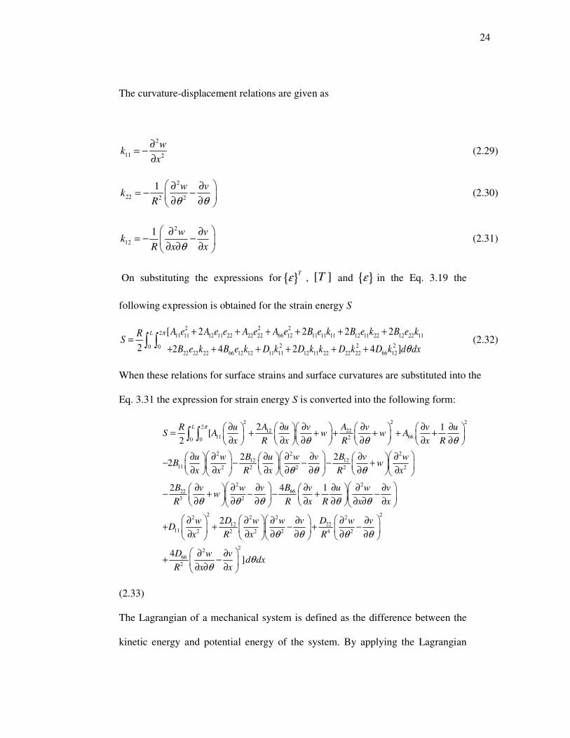
The curvature-displacement relations are given as
2
11 2
wk
x
∂= −
∂ (2.29)
2
22 2 2
1 w vk
R θ θ
∂ ∂= − −
∂ ∂ (2.30)
2
12
1 w vk
R x xθ
∂ ∂= − −
∂ ∂ ∂ (2.31)
On substituting the expressions for T
ε , [ ]T and ε in the Eq. 3.19 the
following expression is obtained for the strain energy S
2 2 22 11 11 12 11 22 22 22 66 12 11 11 11 12 11 22 12 22 11
2 2 20 022 22 22 66 12 12 11 11 12 11 22 22 22 66 12
[ 2 2 2 2
2 2 4 2 4 ]
L A e A e e A e A e B e k B e k B e kRS
B e k B e k D k D k k D k D k d dx
π
θ
+ + + + + +=
+ + + + + +∫ ∫ (2.32)
When these relations for surface strains and surface curvatures are substituted into the
Eq. 3.31 the expression for strain energy S is converted into the following form:
2 2 22
12 2211 6620 0
2 2 2
12 1211 2 2 2 2 2
22
3
2 1[
2
2 22
2
L A AR u u v v v uS A w w A
x R x R x R
B Bu w u w v v wB w
x x R x R x
B vw
R
π
θ θ θ
θ θ θ
θ
∂ ∂ ∂ ∂ ∂ ∂ = + + + + + +
∂ ∂ ∂ ∂ ∂ ∂
∂ ∂ ∂ ∂ ∂ ∂ ∂ − − − − +
∂ ∂ ∂ ∂ ∂ ∂ ∂
∂− +
∂
∫ ∫
2 2
66
2
2 22 2 2 2
12 2211 2 2 2 2 4 2
22
66
2
4 1
2
4]
Bw v v u w v
R x R x x
D Dw w w v w vD
x R x R
D w vd dx
R x x
θ θ θ θ
θ θ θ θ
θθ
∂ ∂ ∂ ∂ ∂ ∂ − − + −
∂ ∂ ∂ ∂ ∂ ∂ ∂
∂ ∂ ∂ ∂ ∂ ∂+ + − + −
∂ ∂ ∂ ∂ ∂ ∂
∂ ∂+ −
∂ ∂ ∂
(2.33)
The Lagrangian of a mechanical system is defined as the difference between the
kinetic energy and potential energy of the system. By applying the Lagrangian

25
principle and writing the Lagrangian energy functional F as the difference
between the two energies given by
the expressions (2.20) and (2.24) and given by
F K S= − (2.34)
2.5 Derivation of Shell Dynamical Equations
Dynamical equations that describe the motion of cylindrical shells are derived by
employing Hamiltonian’s principle on langrangian energy function in Equ.2.34.
Hamiltonian’s Principle was formulated by Sir William Rowan Hamilton (1805-1865),
an Irish Mathematician, in 1835. This principle is one of the significant and vital
achievements of analytical mechanics. It is used in deriving the equation of motion for
many systems with the additional advantage that proper and correct boundary equation
are automatically obtained as a part of the derivation. As any modeling assumption are
obvious and the effect of changing initial system properties become clear, this principle
allows viewing the manner that the system is modeled. Hamilton’s principle can be
applied as the basis for an approximate solution and simplification may also be made. It
describes that dynamics of a physical system is found by a variational problem for a
functional based on a single function, the Lagrangian, which has all physical
information associated with the system and the forces acting on it. The variational
problem is very useful in acquiring the differential equations of motion of the physical
system. Although Hamilton’s principal basically formulated for classical mechanics
and applies to classical fields such as electromagnetic, gravitational field and has even
been extended to quantum mechanics, quantum field theory and criticality theories.
One of the great accomplishments of analytical mechanics, Hamilton’s variational
principle has found use in many disciplines, including optics and quantum mechanics.
The development of the equations of mechanics via variational principle allows the use

26
of powerful approximation techniques for the solution of problems that may not be
otherwise solvable. For example, the Rayleigh-Ritz method has found many
applications in the solution of mechanics problems. For the sake of entirety and to set
up the notation, the principle is first derived in its classical form. Subsequent to this,
extensions and applications of the classical principle are presented.
Mathematically Hamiltonian’s Variational principle expresses as
Consider the integral
2
1
t
t
I F d t= ∫ (2.35)
where the function F is the Lagrangian of the mechanical system defined as the
difference between the kinetic, K, and potential, S , energies of the system, described in
Equ. (2.34) Hamilton’s variational principle states that the integral I taken along a
possible path of motion of a physical system is an extremum when evaluated along an
actual path of motion. In other words, out of the countless ways in which a system
could change its configuration during a time interval between t1 and t2, Nature chooses
the way that either maximizes or minimizes the integral I which is called the action for
the system at hand. Mathematically, this statement can be described as follows:
2
1
0
t
t
I F d tδ δ= =∫ (2.36)
where δ means a variation in the entire integral about its extremum value.
Substituting the expressions for strain and kinetic energies of the shell from the Eqs.
2.20 and 2.24 respectively into the expression (2.34) and then employing the

27
Hamilton’s variational principle [68], the governing equations for shell dynamical
behavior are obtained in the following partial differential equation forms:
2 2 2 3 3 2
12 66 11 66 12 661211 66 112 2 2 3 2 2 2
2 2T
A A B B B BAu u v w w w uA A B
x R R x R x x R x tρ
θ θ θ
+ + +∂ ∂ ∂ ∂ ∂ ∂ ∂ + + + + − − =
∂ ∂ ∂ ∂ ∂ ∂ ∂ ∂ ∂ (2.37)
2 2 2
12 66 11 66 66 66 6622 22662 2 3 4 2 2 2 2
3 3 2
12 66 6622 22 22 22 12
2 3 3 4 3 2 2 2 2
2 2 4 4
2 4T
A A B B B B DA Du v vA
R R x R R R R R x
B B DA B B D Dw w w v
R R R R R R R x t
θ θ
ρθ θ θ
+ + ∂ ∂ ∂ + + + + + + +
∂ ∂ ∂ ∂
+∂ ∂ ∂ ∂ + + − + − + + =
∂ ∂ ∂ ∂ ∂
(2.38)
3 3 3
11 6612 22 22 22 2211 3 2 2 2 3 3 4 3
3 2 2 4
12 66 6612 22 12 22 22
2 2 2 2 2 3 2 4 4
4
661211 4 2 2
2
2 4 2 2
42
B BA A B B Du u u v vB
R x x R x R R R R
B B DD A B B Dv w w ww
R R R x R R x R R
DDwD
x R R
θ θ θ
θ θ θ
+∂ ∂ ∂ ∂ ∂ − − + + − +
∂ ∂ ∂ ∂ ∂ ∂
+ ∂ ∂ ∂ ∂ − + + + − − +
∂ ∂ ∂ ∂ ∂
∂+ + +
∂
4 2
2 2 2T
w w
x tρ
θ
∂ ∂ = −
∂ ∂ ∂
(2.39)

28
Chapter 3
NUMERICAL METHODOLOGY
Various numerical methods are employed to solve the shell dynamical equations
for studying the free vibration characteristics of circular cylindrical shells associated
with fluid effect and without fluid. In literature, different analytical and numerical
methods are utilized to solve the shell problems for different boundary conditions. Del
Rosario and Smith [69] presented a spline-based method for approximating thin shell
dynamics. Accuracy, flexibility and efficiency are the basic requirement of this method
in a smart material application. The ascendancy of this method lies in the accuracy,
being flexible and efficient with regard to boundary condition and material non-
homogeneities. To study the vibration behavior of thin circular cylindrical shells,
Rayleigh – Ritz method, Galerkin Method, finite difference method, generalized
differential quadrature approach and finite element method are most popular methods
used by many researchers. Most commonly the energy variation methods i.e., Rayleigh-
Ritz and Galerkin methods are applied to study the shell Vibrations. Rayleigh –Ritz
variational approach has been most extensively used to study the vibration
characteristics of cylindrical shells. Sewall and Naumann [12], Sharma and Johns’[13]
Sharma[14,15] used Rayleigh –Ritz variational approach to study the shell problem.
These methods range from energy methods based on the Rayleigh-Ritz procedure to
analytical methods in which, respectively, closed-form solutions of the governing
equations and iterative solution approaches were used [70-73]. Naeem et al.[27] used
the Rayleigh – Ritz variational approach to predict the natural frequencies for the thin
circular cylindrical shells. Najafizadeh et al. [28] studied the vibration of functionally

29
graded cylindrical shells based on higher order shear deformation plate theory with ring
support using the Rayliegh- Ritz method. Arshad et al. [29] employed the Rayleigh-
Ritz method to analyze the frequency of functionally graded material cylindrical shell
with various volume fraction laws. Lam and Loy [73] used beam functions as the axial
modal functions in the Ritz procedure to study the effects of boundary conditions on the
free vibration characteristics for a multi-layered cylindrical shell with nine different
boundary conditions. Pradhan et al. [20] utilized the Rayleigh method to study the
vibration characteristics of FGM cylindrical shell made of stainless steel and zirconia
for a number of boundary conditions.
Differential quadrature method is numerical technique and many researchers employed
this technique to solve the variety of problems of engineering and physical sciences.
Bert and Malik [74] studied the free vibration analysis of thin cylindrical shells by the
application of differential quadrature method. Differential Quadrature method and
Generalized Differential Quadrature method which is the improved version of
Differential Quadrature method has been also used to study the shell problem. Loy et
al. [17] applied the generalized differential quadrature (GDQ) method for solving the
vibration of cylindrical shells.
Goncalves and Batista [35, 44] used the Galerkin approach to investigate the free
vibration of simply supported vertical cylindrical shell filled with or submerged in a
fluid. In case of application of the Galerkin technique the axial modal dependence is
approximated by characteristic beam functions for solving the shell equations.This
involve the integrals of these functions. The evaluation of the integrals requires a very
lengthy process of integration.
The expressions for the modal displacement deformations are supposed as the product
of functions of space and time variables. In the product each function is a function of a

30
single independent variable. The substitution of the functions separates the variables.
This leads to a system of ordinary differential equations of three unknown functions of
the axial space variable. Different types of functions are chosen to approximate the
axial modal dependence. These functions satisfy the boundary conditions. Well-known
functions are beam functions [66,67], Ritz polynomial functions [27,75,76], orthogonal
polynomials [77,78], Fourier series of trignometric functions[79]. Adaptation of these
functions implicates a large amount of algebraic manipulations.
To overcome these complexities, Zhang et al.[80] developed a very simply technique
known as “wave propagation approach” by taking the approximate eigenvalues of the
beam functions. This approach is very simple and easily applicable and gives accurate
and robust results. Many researcher investigated the wave propagation in cylindrical
shells. Harari [81] applied the wave propagation in shells with a wall joint. The
discontinuity consisted of a spring-type rubber insert and the results obtained showed
high-power reflection coefficients at the cut-on frequencies of various torsional waves.
Fuller [82] also applied the wave propagation for the investigation of the effects of
discontinuities on the wall of a cylindrical shell in vacuum on traveling flexural waves.
Wang et al. [83] employed this approach to predict natural frequencies of finite length
circular cylindrical shells. Zhang et al [80] analyzed the Vibration of thin cylindrical
shells by using wave propagation approach and found that this approach is very simple,
effective, convenient and accurate and easy to use. Li [84] studied the free vibrations
analysis of circular cylindrical shells using wave propagation approach. It is observed
that the wave propagation approach is more efficient and gives the more accurate
results than resulte calculated by others numerical techniques.
Zhang et al. [85] investigated the frequency analysis of submerged cylindrical shells
with the wave propagation approach. He found that with the wave propagation

31
approach one can calculate the coupled frequency of submerged cylindrical shells much
easily and quickly. This approach can handle various boundary conditions of the shell
easily. The result compared with the other methods like FEM/ BEM and find out that
the wave propagation is much quicker and easy to employ.
In [86] Zhang et al. investigated the coupled vibration analysis of fluid-filled cylindrical
shell using wave propagation approach and concluded that this approach is very simple
non – iterative and less computationally intensive method. Mumtaz and Naeem [87]
studied the vibration characteristics of rotating FGM circular cylindrical shells by
employing the wave propagation approach. Zhang [88] employed the wave propagation
approach to study the vibration analysis of cross – ply laminated composite cylindrical
shells. Gan et al. [89] used the wave propagation which is a simple, non-iterative
method and investigated the free vibration analysis of a ring-stiffened cylindrical shell
under hydraulic pressure.
Iqbal et al.[ 30] has studied the vibration characteristics of FGM circular cylindrical
shells by employing the wave propagation approach and an axial modal dependence is
approximated by exponential functions. Iqbal et al. [49] investigated vibration
characteristics of FGM shells containing fluid and compared the uncoupled and coupled
frequencies of the shells by employing the wave propagation approach.
3.1 Solution Procedure
In the present study of the vibration characteristics of functionally graded material
circular cylindrical shells, the wave propagation approach is used. This method is
convenient, effective and accurate. The expressions for modal displacement
deformations are assumed as:

32
( ) ( ), , s i n ( ) mi t i k x
mu x t A n e
ωθ θ −= (3.1)
( ) ( ), , c o s ( ) mi t i k x
mv x t B n e
ωθ θ −= (3.2)
( ) ( ), , s i n ( ) mi t i k x
mw x t C n e
ωθ θ −= (3.3)
in the axial, circumferential and radial directions respectively where the coefficients
, ,m m m
A B C denote wave-amplitudes respectively in the x, θ and z directions and n is
the number of circumferential waves, km is the axial wave numbers that have been
specified for different boundary conditions in the table 1 and ω is the natural circular
frequency for the cylindrical shell.
On substituting the expressions of u, v and w from Eq. 3.1-3.3 into Eq. 12, the
frequency equation is obtained in the form of the eigenvalue problem:
11 12 13
2
12 22 23
13 23 33
1 0 0
0 1 0
0 0 1
m m
m t m
m m
T T T A A
T T T B B
T T T C C
ω ρ
− = −
(3.4)
where the entries T11, T12, T13, T22, T23, T23, and T33 are given in Appendix 1.
The powerful software package MATLAB is used to solve the eigenvalue problem for
the natural frequencies and mode shapes. MATLAB software is very helpful in
calculation because only one program gives the shell frequencies by changing the
values of axial wave number for a boundary condition. The wave propagation approach
is adapted here in this study.
3.2 The Fluid Filled In the FGM Cylindrical Shell
The FGM shell is filled with incompressible, non viscous fluid. For incompressible fluid
filled, its density is assumed as constant while the changes in temperature produced

33
changes in the density of compressible fluid and it will complicate the analysis. Owing
to this, it is assumed that the fluid filled is incompressible. It is also suppose that the
fluid is non viscous.
The study of all mechanical waves in solid, liquids and gases is dealt by acoustics, an
interdisciplinary science. The acoustic wave equation expresses sound waves in a liquid
or gas. The fluid filled in the cylindrical shell satisfies the acoustic wave equation and
the equation of motion of the fluid can be expressed in the cylindrical co- ordinate
system ( , , )x rθ as
2 2 2
2 2 2 2 2
1 1 1( )r
r r r r x c t
ψ ψ ψ ψ
θ
∂ ∂ ∂ ∂ ∂+ + =
∂ ∂ ∂ ∂ ∂ (3.5)
Where t denotes the time, the acoustic pressure and the sound speed of the fluid are
represented by ψ and c respectively. The x and θ co-ordinates are the same as those
of the shell and r coordinate is obtained from the axis of the shell.
3.3 Bessel Functions
Bessel functions are extensively related with many problem of mathematical physics.
Bessel function theory is employed to problems of acoustics, radio physics,
hydrodynamics and atomic and nuclear physics. Bessel's equation arises when finding
separable solutions to Laplace's equation and the Helmholtz equation in cylindrical or
spherical coordinates. Bessel functions are vital for many problems of wave
propagation and static potentials. The Bessel functions of integer order (α = n) is
obtained in solving problems in cylindrical coordinate systems and in spherical
problems the Bessel functions are of half-integer orders (α = n + ½). For example:
• electromagnetic waves in a cylindrical waveguide
• heat conduction in a cylindrical object.

34
• modes of vibration of a thin circular artificial membrane
• diffusion problems on a lattice.
The related form of the acoustic pressure field in the contained fluid, which satisfies the
acoustic wave Eq. (3.5), can be expressed in the cylindrical coordinate system,
associated with an axial wave numberm
k , radial wave number r
k and circumferential
modal parameter n and given as
( )cos( ) ( ) miwt ik x
m n rn J k r eψ ψ θ −
= (3.6)
Where ( )n
J denotes the Bessel function of order n.
The radial wave number r
k is related to the axial wave number m
k by the usual vector
relation
2 2 2 2( ) ( / ) ( )r L f mk R C C k R= Ω − (3.7)
where Ω is the non-dimensional frequency parameter and L
C and f
C are the sound
speed of the shell and fluid respectively.
The fluid radial displace and the shell radial displacement must be equal at the interface
of the shell inner wall and the fluid to ensure that the fluid to remain in contact with the
wall of the shells.
This coupling condition becomes as
1/ ( ) ( / ) ( / )f r R r Ri r w tωρ ψ = =− ∂ ∂ = ∂ ∂ (3.8)
and 2 / ' ( )m f r n r mk J k R Wψ ω ρ = (3.9)
Wheref
ρ is the density of the contained fluid and the prime on the ( )n
J represents
differentiation with respect to the argument .r
k R

35
Equation for the motion of coupled system are obtained in the matrix form as
11 12 13
21 22 23
31 32 33
0
0
0
m
m
m
C C C U
C C C V
C C C FL W
= +
(3.10)
Where ( , 1, 2,3)ij
C i j = are the parameters obtained from the ij
L after they are operated
with the x andθ . FL denotes the fluid loading term because of the occurrence of the
fluid acoustic field and is given by
2 1 '( / )( / )( ) ( ) / ( )f s r n r n rFL R h k R J k R J k Rρ ρ − = Ω (3.11)
where andf s
ρ ρ are the fluid and shell density respectively.
The frequency equation is derived in the shape of the eigenvalue problem:
11 12 13
2
12 22 23
13 23 33
1 0 0
0 1 0
0 0 1
m m
m t m
m m
T T T A A
T T T B B
T T T C C
ω ρ
− = −
(3.12)
where the entries T11, T12, T13, T22, T23, T13, and T33 are given in the Appendix II.
If fluid loading terms are neglected then the expression of shell frequency equation is
obtained for the uncoupled system.

36
Chapter 4
NUMERICAL RESULTS AND DISCUSSION
In this chapter the vibration of functionally graded circular cylindrical shells are studied
and analyzed for various parameters.
4.1 Comparisons Of The Results
The natural frequencies for the isotropic cylindrical shells obtained by the present
method are compared with the corresponding results available in some previous studies.
The geometrical parameters for shells are listed in the relevant tables.
4.2 Isotropic Circular Cylindrical Shells
The natural frequencies of isotropic cylindrical shells are given in tabular form to check
the validity, efficiency and accuracy of the present method some comparisons of results
are made for various boundary conditions. In Table 4 the non-dimensional frequency
parameters 2(1 ) /R Eω υ ρΩ = − are given for an isotropic cylindrical shell with
simply supported edge conditions at both ends and are compared with those values
calculated by Loy et al. [17]. The values of frequency parameters are obtained for the
axial wave number m=1 and L/R=20, h/R=0.01 are taken as geometrical parameters. It
is observed that the agreement between the two sets of results is very good and the
present method is valid, efficient and accurate. In Table 5 frequency parameters for an
isotropic cylindrical shell are given for clamped-clamped boundary conditions and a
comparison is performed with those determined by Zhang et al. [80]. It is seen that the
two sets of frequencies agreed well with each other.

37
In Table 6 the values of the frequency parameter for a cylindrical shell with simply
supported boundary conditions for m=1, R/L=.05v=0.3 are listed and comparison are
made with those values calculated by Zhang et al.[ 80]. It is observed that the two sets
of values are very close to each other which prove the accuracy of the present method.
Table 7 represents the comparison of the frequency for isotropic circular cylindrical
shell for a cylindrical shell with clamped -clamped boundary conditions for m=1, 2,
h/R=.002, L/R=20, v=0.3 with those values calculated by the Zhang et al. [ 80]. Both
values are very close to each others.
In table 8 shows the comparison of the uncoupled frequency for a cylindrical shell for
simply supported –simply supported boundary conditions obtained by Goncalves et al.
[44] with those values calculated by the present method. It is observed that the values
are slightly less than those obtained by reference [44].
4.3 Comparison of Results for Functionally Graded Material Circular Cylindrical
Shell.
The natural frequencies of FGM circular cylindrical shell obtained by the present
method are compared with the result available in literature. In table 10 the natural
frequencies (Hz) for a simply supported functionally graded circular cylindrical shell
are listed for the half-axial wave number m=1 with geometrical parameters: L/R= 20
and h/R= 0.002 and are compared with those evaluated by Loy et al. [19]. The values of
volume fraction exponent N taken into consideration are N = 0.5, 1, 15. The shell is
composed of stainless steel at the inner surface and nickel at the outer surface of the
shell. The two sets of the natural frequencies are very close to each other.

38
From all these comparisons it is obvious that the present wave propagation approach is
efficient, accurate, and simple and can be easily employed to perform the vibration
analysis of cylindrical shells.
4.4 Conclusion about the Present Method
All the comparisons of the results obtained by the present method with those available
in literature provide the ample evidences of efficiency, accuracy and simplicity of the
present method “wave propagation approach”. This technique is most appropriate to
employ for the vibration analysis of FGM circular cylindrical shells. The present
method is most suitable to obtain the very accurate results.
4.5 Numerical Result for the FGM Circular Cylindrical Shells
The present work explores the vibration characteristics of FGM circular cylindrical
shells for a number of boundary conditions. The FGM cylindrical shells are fabricated
from three types of materials viz., stainless steel, nickel and zirconia. Six types of FGM
circular cylindrical shells are assumed to be constructed by changing the order of the
materials constituting the shell listed in table 1. Material properties for stainless steel,
nickel and zirconia are obtained at T=300K and are presented in table.3
In this study each shell is composed of two constituent materials M1 and M2 and its
material properties are distributed gradually in the thickness direction in accordance
with a volume fraction power law. The material M1 forms the inner surface and
material M2 forms outer surface of the shells. Thus the material properties of inner side
of the shells are those of the constituent material M1 while on the outer surface are
those of the constituent material M2.

39
4.6 Effect Of Volume Fraction On The Frequency Of The Shell
The effect of volume fraction on natural frequencies studied here.
The volume fractions V1 and V2 for the materials M1 and M2 respectively are defined by
1( 0.5)
NzV
h= + 4.1
21 ( 0.5) ,(0.5 0.5 )Nz
Vh
h z h= − + ≤ ≤ − 4.2
Where N is the power law exponent that governs the degree of material grading and
0 N≤ ≤ ∞ . In Fig. 2 variations of volume fractions 1 and 2 of materials M1 and
M2 respectively are drawn with thickness variable z/h in the radial direction. It is
observed that In the Fig.2 volume fraction V1 of material M1 decreases from 1 at z=-0.5h
to 0 at z=0.5h and volume fraction V2 of material M2 increases from 0 at z=-0.5h to 1 at
z=0.5h for any value of N. The total volume fractions of the materials M1 and M2 equal
unity. In Fig 2 the rate of decrease of V1 for N < 1 is high for z < 1 as it compared to N >
1 and for z > 0 the rate of decrease of V2 for N > 1 is much higher than for N < 1.
Similarly the rate of increase of V2 for N < 1 is higher than N >1 but for z > 0 the rate of
increase of V2 for N > 1 appears to be higher than for N < 1. Hence when V1 is low V2 is
higher and vice versa. It is observed that the variation of volume fractions of functionally
graded constituent materials has effect on the frequencies of cylindrical shells by
interchanging the material configuration in the shell.

40
4.7 Frequency Analysis For Of FGM Circular Cylindrical Shells
The natural frequencies (Hz) for FGM circular cylindrical shell for different types of
shells are calculated here. For Type I of the shells the inner material M1≡ Stainless steel
and outer material M2 ≡ Nickel, in type III inner material M1≡ Zirconia and outer
material M2 ≡ Stainless steel and for type V inner material M1≡ Zirconia and outer
material M2 ≡ Nickel. The frequencies of the functionally graded material circular
cylindrical shell are calculated for simply supported-simply supported (SS-SS);
clamped-simply supported ( C-SS)and clamped-clamped(C-C) boundary conditions. In
table 12-14 the frequencies of type I of the shells are listed for simply supported-simply
supported; clamped-simply supported and clamped-clamped boundary conditions. Table
18-20 represent the frequencies of shells of type III for simply supported-simply
supported; clamped-simply supported and clamped-clamped boundary conditions and in
table 24-26 the values of frequencies of the shells for type V are given for three
boundary conditions. The geometrical parameters are L/R=20, h/R=0.002 and the axial
wave number is m=1. The values of power law exponent are N=0.3, 0.7, 1, 3, 15, 25. It
is observed that the minimum frequency occurs in between n equals 2 and 3 for all
boundaries conditions and also the shell frequency is impressed minutely by increasing
the value of N. Moreover the influence of boundary conditions on the shell frequencies
gets more prominent by adding the more constraint. The frequencies for the shell with
clamped-clamped conditions are higher than those for the shells with clamped-simply
supported and simply supported-simply supported conditions. Also by varying the value
of power law exponent N, natural frequencies of the FGM circular cylindrical shell are
computed for boundary conditions. From these values of the frequencies, it is noted that
the value of frequency of the FGM circular cylindrical shell lies within the frequencies

41
of pure inner material and pure outer material. Frequency of the FGM shell is close to
that of pure inner material M1 for small value of N and frequency of the FGM shell is
close to the frequency of the pure outer material M2 for large value of N. It shows that
the value of frequency of FGM shell vary by changing the value of volume fraction
exponents.
The values for the natural frequencies (Hz) for FGM circular cylindrical shells for Type
II are listed in the table 15-17, for Type IV in tables 21-23 and for Type VI are listed in
table 27-29 for simply supported-simply supported, clamped-simply supported and
clamped-clamped boundary conditions. In type II inner material M1≡ Nickel and outer
material M2 ≡ Stainless steel, in type IV inner material M1≡ Stainless steel and outer
material M2 ≡ Zirconia and for type VI inner material M1≡ Nickel and outer material M2
≡ Zirconia. The frequencies are calculated for simply supported-simply supported,
clamped-simply supported and clamped-clamped boundary conditions. The geometrical
parameters are L/R=20, h/R=0.002 and the axial wave number is m=1. The value of
natural frequencies decrease with N for all boundary conditions. The trends found in
frequencies for Type II, IV Type VI are opposite to those found in Type I Type III and
Type V. The influence of N or the constituent volume fraction on the natural frequencies
is the opposite of Type I, Type III and Type V cylindrical shells. It is noted that the
frequency characteristics shown by circular cylindrical shells made of functionally
graded material is similar to the homogeneous isotropic cylindrical shells. A circular
cylindrical shell fabricated by functionally graded material shows very interesting
frequencies characteristics with the variation of constituent volume fraction due to
functionally graded material. It is possible only when the values of power law exponent
N varies.
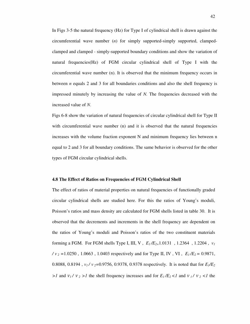
42
In Figs 3-5 the natural frequency (Hz) for Type I of cylindrical shell is drawn against the
circumferential wave number (n) for simply supported-simply supported, clamped-
clamped and clamped - simply-supported boundary conditions and show the variation of
natural frequencies(Hz) of FGM circular cylindrical shell of Type I with the
circumferential wave number (n). It is observed that the minimum frequency occurs in
between n equals 2 and 3 for all boundaries conditions and also the shell frequency is
impressed minutely by increasing the value of N. The frequencies decreased with the
increased value of N.
Figs 6-8 show the variation of natural frequencies of circular cylindrical shell for Type II
with circumferential wave number (n) and it is observed that the natural frequencies
increases with the volume fraction exponent N and minimum frequency lies between n
equal to 2 and 3 for all boundary conditions. The same behavior is observed for the other
types of FGM circular cylindrical shells.
4.8 The Effect of Ratios on Frequencies of FGM Cylindrical Shell
The effect of ratios of material properties on natural frequencies of functionally graded
circular cylindrical shells are studied here. For this the ratios of Young’s moduli,
Poisson’s ratios and mass density are calculated for FGM shells listed in table 30. It is
observed that the decrements and increments in the shell frequency are dependent on
the ratios of Young’s moduli and Poisson’s ratios of the two constituent materials
forming a FGM. For FGM shells Type I, III, V , E1 /E2=1.0131 , 1.2364 , 1.2204 , v1
/ v 2 =1.0250 , 1.0663 , 1.0403 respectively and for Type II, IV , VI , E1 /E2 = 0.9871,
0.8088, 0.8194 , v1 / v 2=0.9756, 0.9378, 0.9378 respectively. It is noted that for E1/E2
>1 and v1 / v 2 >1 the shell frequency increases and for E1 /E2 <1 and v 1 / v 2 <1 the

43
shell frequency decreases. But the ratio ρ1 / ρ 2 does not seem to affect the increase and
decrease with regard to volume fraction exponents N.
4.9 The Variation of Resultant Material Properties
The variation of the resultant material properties E, v, ρ of an FGM are sketched with
along the thickness variable (z/h) in the Fig. 9-11. When M1 ≡ stainless steel M2 ≡
nickel, the variation of the resultant E , v , ρ are similar to that of the variation of the
volume fraction V1, V2 depending upon the order of constituent materials in a FGM
cylindrical shell. Similarly Figs 12-14 show the variation of resultant material
properties E, v, ρ of an FGM with the thickness variable when M1 ≡ Nickel, M2 ≡
Stainless steel. It is seen that from figs the variation of the resultant E, v, ρ exhibit the
opposite behavior. It is observed that the behavior of the resultant material reversed if
the constituent materials are interchanged from inner to out side of the FGM shells.
Similar to that of the variation of these material properties for other is similar to that of
the variation of volume fraction with thickness variable. The part of this chapter has
been published in the form of paper [38]

44
Chapter 5
NUMERICAL RESULTS FOR THE VIBRATION OF FGM CYLINDRICAL
SHELLS CONTAINING FLUID
The vibration characteristics of functionally graded material circular cylindrical shell
containing fluid are examined by employing the wave propagation approach. The shell
is filled with a non-viscous and incompressible fluid. Study of vibration characteristics
of functionally graded cylindrical shells filled with fluid is of great importance and
well-established field of research in structural dynamics. Shells with fluid are used in
many types of engineering structures such as pressure vessels, oil tanker, aero planes,
ships and marine crafts etc. The results calculated by the present methods are compared
with those available in the literature.
5.1 Comparison of the Results
In Table 8 the uncoupled frequencies for a cylindrical shell with simply supported –
simply supported boundary conditions are compared with those calculated by
Goncalves et al[ 44]. It is seen from the table that both the results are very close to each
others the result obtained by the present method are slightly less than the result
calculated by Goncalves. Table 9 gives the comparison of the coupled frequency for a
cylindrical shell with simply supported –simply supported boundary conditions. The
results obtained by the present method are less than those calculated by Conclaves et al.
[44]. In Table 11 the uncoupled and coupled non-dimensional frequency parameters
2(1 ) /R Eω υ ρΩ = − are given for an isotropic cylindrical shell for clamped –
clamped edge conditions and are compared with those values determined by Zhang et
al. [40]. They solved the polynomial frequency equation numerically whereas in present

45
study MATLAB command has been used to solve the eigenfrequency equation. The
values of frequency parameters are obtained for the axial wave number m=1, 2, 3 and
L/R=20, h/R=0.01 are taken as geometrical parameters. It is observed that the present
results are very close and some bit lower to those obtained in the reference [40].
All the comparisons of the results obtained provide the ample evidences of efficiency,
accuracy and simplicity of the present method “wave propagation approach”. This
technique is most appropriate to employ for the vibration analysis of FGM circular
cylindrical shells.
5.2 Comparison of Couple and Uncouple Frequencies of the FGMs shells
In this study, vibration characteristics of functionally graded circular
cylindrical shells containing fluid are investigated for a number of boundary conditions.
The shells are assumed to be fabricated from stainless steel and nickel as FG constituent
materials. By changing the configuration of shell materials, they are classified into two
types. FG shell of Type I consists of stainless steel at the inner surface and the nickel at
the outer one whereas in Type II the order of constituent materials is reversed. In the
present work the functionally graded circular cylindrical shell is filled with water of
mass density 3ρ =1000 kg/m
3 and sound speed c=1500 m/s. Material properties for
stainless steel and nickel are calculated at T=300K and are presented in Table 3. Coupled
frequencies of the Type I and Type II cylindrical shells are evaluated for simply
supported-simply supported (SS-SS), clamped-simply supported (C-SS) and clamped-
clamped (C-C) end conditions.
In table 31 the comparison and variation of coupled and uncoupled natural frequencies
(Hz) of Type I cylindrical shell for simply supported-simply supported boundary
condition are listed. It is observed that the frequency increase with N for simply

46
supported-simply supported boundary condition. It is observed that the coupled
frequency of the shell increases with the circumferential wave number whereas it varies
for the uncoupled case like the isotropic shell without fluid. But for the axial wave
number it increases with m. The frequency increases as the boundary constraints are
added more. It is also seen from the tables that the coupled frequencies is less than the
uncoupled frequency of the FG cylindrical shells. The frequency is affected by the load
fluid. Variation in coupled frequency is similar as the variation in uncoupled frequency
of FG cylindrical shells. As Uncoupled frequency of FG shells increases with N,
similarly coupled frequency also increases with N. For type of FGM shells the ratio of
coupled and uncoupled frequency shows that there is increase in ratio of coupled
frequency to uncoupled frequency increases with the values N but the ratio decreases as
circumferential wave number increases for fixed value of N. The ratio of coupled to
uncoupled frequency decreases with increases value of N and also decreases with
circumferential wave number for fixed values of N.
In table 32 the comparison and variation of coupled and uncoupled natural frequencies
(Hz) of Type I cylindrical shell for clamped-clamped boundary condition are given. It is
observed that the frequency also increase with N for clamped – clamped boundary
condition. It also increases with the circumferential wave number for the coupled case
whereas it varies for the uncoupled case like the isotropic shell without fluid. But for the
axial wave number it increases with m. It is also seen from the tables that the coupled
frequencies is less than the uncoupled frequency of the FG cylindrical shells. The effect
of fluid on frequency is very clear and the coupled frequency is less as the fluid is added
in the cylindrical shells. Variation in coupled frequency is similar as the variation in
uncoupled frequency of FG cylindrical shells. As Uncoupled frequency of FG shells
increases with N, similarly coupled frequency is less than the uncoupled frequency but

47
increases with N. For type I of FGM shell the ratio of coupled and uncoupled frequency
shows that there is increase in ratio of coupled frequency to uncoupled frequency
increases with the values N but the ratio decreases as circumferential wave number
increases for fixed value of N. The ratio of coupled to uncoupled frequency decreases
with increases value of N and also decreases with circumferential wave number for fixed
values of N.
The comparison and variation of coupled and uncoupled natural frequencies (Hz) of
Type I cylindrical shell for simply supported-clamped boundary condition is shown in
Table 33. It is noticed that the frequency for simply supported-clamped boundary
condition increase with N. It observed that the coupled frequency increases with the
circumferential wave number whereas it varies for the uncoupled case like the isotropic
shell without fluid. But for the axial wave number it increases with m. The frequency
increases as the boundary constraints are added more. It is also seen from the tables that
the coupled frequencies is less than the uncoupled frequency of the FG cylindrical shells.
The fluid added in the cylindrical shell effect the frequency. Variation in coupled
frequency is similar as the variation in uncoupled frequency of FG cylindrical shells. As
Uncoupled frequency of FG shells increases with N, similarly coupled frequency also
increases with N. For type of FGM shells the ratio of coupled and uncoupled frequency
shows that there is increase in ratio of coupled frequency to uncoupled frequency
increases with the values N but the ratio decreases as circumferential wave number
increases for fixed value of N. The ratio of coupled to uncoupled frequency decreases
with increases value of N and also decreases with circumferential wave number for fixed
values of N.
In table 34-36 the coupled and uncoupled natural frequencies (Hz) of Type II cylindrical
shells for simply supported-simply supported, clamped-simply supported and clamped-

48
clamped boundary conditions are given. With the keen view of the results it is noticed
that the frequency for simply supported-clamped boundary condition decrease with N. It
is also observed that both coupled and uncoupled frequencies decrease with the
circumferential wave number whereas it varies for the uncoupled case like the isotropic
shell without fluid. It is also seen from the tables that the coupled frequencies is less than
the uncoupled frequency of the FG cylindrical shells. The fluid added in the cylindrical
shell effect the frequency. Variation in coupled frequency is similar as the variation in
uncoupled frequency of FG cylindrical shells. As Uncoupled frequency of FG shells
increases with N, similarly coupled frequency also increases with N. For type II of FGM
shells the ratio of coupled and uncoupled frequency shows that there is decrease in ratio
of coupled frequency to uncoupled frequency with the values N but the ratio decreases as
circumferential wave number increases for fixed value of N. The ratio of coupled to
uncoupled frequency decreases with increases value of N and also decreases with
circumferential wave number for fixed values of N. It is noticed from all the tables that
the coupled and uncoupled frequencies are highest for the clamped-clamped and lowest
for the simply supported boundary conditions. It is clearly seen from the results that the
behavior of variation of uncoupled and coupled frequency of FGM circular cylindrical
shells for Type 1 is opposite to that for Type I of the shells.
In Figures 15-17 the coupled natural frequency (Hz) for Type I of FGM circular
cylindrical shell is drawn against the circumferential wave number (n) for simply
supported-simply supported, clamped-clamped and clamped-simply supported
boundary conditions and it is observed that the variation in coupled frequency is similar
to the uncoupled frequency but is less than the uncoupled frequency for all the
boundary conditions. The same behavior is exhibited by the Type II of FGM cylindrical
shell for simply supported -simply supported, clamped-clamped and clamped-simply

49
supported boundary conditions. Fig.18 shows the variation of coupled frequency of
Type I FGM circular cylindrical shell with circumferential wave number (n) for fixed
value of N for three boundary conditions. It is observed that the natural frequency for
clamped-clamped boundary condition is greater and is lower for the simply supported-
simply supported condition. The same trends for the Type II of shells are observed. In
Fig.19 the variation of frequency with volume fraction N for type I and Type II are
drawn. It shows the frequency of FGM shell increases as the values of N increases and
for type II there is decrease in frequency with the values of N.
This work has been published in the form of paper [49]

50
5.3 CONCLUDING REMARKS
In this analysis the vibration frequencies of FGM circular cylindrical
shells without fluid and containing fluid are studied with regard to the volume fraction
laws. The wave propagation approach is employed to solve the shell governing
equation and is based on approximate eigenvalue of characteristic beam functions. This
approach is very simple and efficient and gives accurate and robust results. The natural
frequencies for the isotropic FGM circular cylindrical shells obtained by the present
method are compared with the corresponding results available in some previous studies
for different geometrical parameters to check the efficiency and validity of the present
approach. It is observed that the present method is very efficient and gives the quick
results. It is also observed that there is analogy between the results calculated by the
present technique with those available in the literature. This research analyzed the
vibration of cylindrical shells made of functionally graded material. Three types of
materials viz; stainless steel, nickel and zirconia are utilized to fabricate the cylindrical
shells. The FGM shell is composed of two material M1 and M2 and six different types
of shells are obtained. The frequencies of all six types of shells are calculated for
different boundary conditions. It os observed that the variation of FGM cylindrical
shells natural frequency with circumferential wave number is similar to the one for an
isotropic shell. The shell frequencies varied with power law exponent for three
boundary conditions i.e., simply supported-simply supported, clamped-simply
supported and clamped-clamped. The effect of volume fraction on natural frequencies
studied also studied here. The frequencies for the shell with clamped-clamped
conditions are higher than those for the shells with clamped-simply supported and
simply supported-simply supported conditions. Also by varying the value of power law

51
exponent N, natural frequencies of the FGM circular cylindrical shell are computed for
boundary conditions.
It shows that the value of frequency of FGM shell vary by changing the value of volume
fraction exponents. It is observed that the minimum frequency occurs in between n
equals 2 and 3 for all boundaries conditions and also the shell frequency is impressed
minutely by increasing the value of N. The frequencies decreased with the increased
value of N. The effect of ratios of material properties on natural frequencies of
functionally graded circular cylindrical shells is studied.
Next the vibration of FGM circular cylindrical shell filled with fluid is analyzed for
different boundary conditions. The coupled frequencies of circular cylindrical shells are
obtained and the results are compared with those available in the literature. The both
results are very close to each other which ensure the validity of the present technique the
wave propagation approach. The coupled frequencies of functionally graded material
circular cylindrical shells filled with fluid are analyzed here. The shell is fabricated from
stainless steel and nickel and two different types of shells are obtained. The frequencies
of two types of shells are calculated for different boundary conditions. It is observed that
the coupled frequencies (Hz) of the FGM shell are affected by the fluid. There is a
remarkable decreased in the coupled frequency (Hz) of the FGM shell as compared to
the uncoupled frequency of the FGM circular cylindrical shell. It is also noted that the
ratio of coupled to uncoupled frequency decreases with increases value of N and also
decreases with circumferential wave number for fixed values of N.
The present analysis can be extended to study other shell problems like vibration of
rotating shells containing fluid, vibration of shells containing fluid with elastic
foundation vibration of FGM shells with holes for different boundary conditions and for
laminated shells.

52
Bibliography
[1] Koizumi, M.: The concept of FGM. Ceramic Transactions, Functionally
Gradient Materials; 34(1):3–10 (1993).
[2] Koizumi, M.: FGM activities in Japan. Composites Part B Engineering;
28(1–2):1–4(1997).
[3] Wang, B.L., Han, J.C., Du, S.Y.: Crack problems for functionally graded
materials under transient thermal loading. Journal of Thermal Stresses;
23(2):143–68 (2000).
[4] Kim, K. S., Noda, N.: Green’s function approach to solution of transient
temperature for thermal stresses of functionally graded material. JSME
International Journal Series A – Solids Mechanics and Material Engineering;
44(1):31–6 (2001).
[5] Na, K.S., Kim, J.H.: Three-dimensional thermo-mechanical buckling analysis
for functionally graded composite plates. Composite Structures; 73(4):413–22
(2006).
[6] Ootao, Y., Tanigawa, Y.: Three-dimensional solution for transient thermal
stresses of an orthotropic functionally graded rectangular plate. Composite
Structures; 80(1):10–20 (2007).
[7] Tanigawa, Y.: Some basic thermoelastic problems for nonhomogeneous
structural materials. Applied Mechanics Reviews; 48(6):287–300 (1995).
[8] Suresh, S., Mortensen, A.: Functionally graded metals and metal–ceramic
composites Part 2. Thermomechanical behaviour. International Materials
Reviews; 42(3):85–116 (1997).

53
[9] Love, A.E.H.: A treatise on the mathematical theory of elasticity. 4th
Ed.
Cambridge University Press; (1952).
[10] Arnold, R.N., Warburton, G.B.: Flexural vibration of the walls of thin
cylindrical shell having freely supported ends. Proc. Roy. Soc. (London) series
A ; 197: 238-256 (1949).
[11] Arnold, R.N., Warburton, G.B.: Flexural vibration of thin cylinders. Proc. Inst.
Mech. Engrs; (London) (167) 63-80 (1953).
[12] Sewal, J., Naumann, I., E.C.: An experimental and analytical vibration study of
thin cylindrical shells with and without longitudinal stiffeners. NASA TN D-
4705 (1968).
[13] Sharma, C.B., Johns, D.J.: Vibration characteristics of a clamped free and
clamped ring stiffened circular cylindrical shells. Journal of Sound and
Vibration; 14: 459-474 (1971).
[14] Sharma, C. B.: Calculation of natural frequencies of fixed free circular
cylindrical shells. Journal of Sound and Vibration 63 (4) : 581-592 (1979).
[15] Sharma, C.B.: Vibration characteristics of thin circular cylinders. Journal of
Sound and Vibration. 63(4): 581-592 (1979).
[16] Blevins, A. W.: Formulas for natural frequency and mode shape. New York:
Van Nostrand Reinhold. (1979).
[17] Loy, C. T., Lam, K. Y., Shu, C.: Analysis of cylindrical shells using
generalized differential quadrature. Shock and Vibration; 4: 193-198 (1997).
[18] Callahan.J, Baruh, H. : A closed-form solution procedure for circular cylindrical
shell vibrations. International Journal of Solids and Structures; 36: 2973-3013
(1999).

54
[19] Loy, C. T., Lam, K. Y., Reddy, J. N.: Vibration of functionally graded
cylindrical shells. International Journal of Mechanical Sciences; 41: 309–324
(1999).
[20] Pradhan, S. C., Loy, C. T., Lam, K. Y., Reddy, J. N.: Vibration characteristics
of functionally graded cylindrical shells under various boundary conditions.
Applied Acoustics; 61: 119–129 (2000).
[21] Han, X., Liu, G.R., Lam, K. Y.: Transient waves in plated of functionally
graded materials. Int. J. Mech. Engng ; 52, 851-865 (2001).
[22] Han, X., Liu, G. R., Xi, Z. C., Lam, K. Y.: Characteristics of waves in a
functionally graded cylinder. International Journal of Mechanical Engineering;
53: 653-676 (2002).
[23] Gong, S. W., Lam, K. Y., Reddy, J. N.: The elastic response of functionally
graded cylindrical shells to low-velocity impact. International Journal of Impact
Engineering; 22: 397–417 (1999).
[24] Ng, T. Y., Lam, K. M., Liew, K. M., Reddy J. N.: Dynamic stability analysis of
functionally graded cylindrical shells under periodic axial loading. International
Journal of Solids and Structures; 38: 1295–1309 (2001).
[25] Yang, Y.Y.: Time-dependent stress analysis in functionally graded materials.
International Journal of Solids and Structures; 37: 7593–608 (2000).
[26] Naeem, M. N., Sharma, C. B.: Prediction of natural frequencies for thin circular
cylindrical shells. Proc Instn Mech Engrs Part C; 214: 1313 -128 (2000).
[27] Naeem, M.N.: Vibrational frequency analysis of non-rotating and rotating FGM
circular cylindrical shells. Ph.D. Thesis submitted to the University of
Manchester Institute of Science and Technology, Manchester (2002).

55
[28] Najafizadeh, M.M., Isvandzibaei, M.R.: Vibration of functionally graded
cylindrical shells based on higher order shear deformation plate theory with ring
support. Acta Mechanica.; 191: 75-91 (2007).
[29] Arshad, S.H., Naeem, M. N., Sultana, N.: Frequency analysis of functionally
graded material cylindrical shells with various volume fraction law. Journal of
Mechanical Engineering Science; 221: 1483-1495 (2007).
[30] Iqbal, Z., Naeem, M. N., Sultana, N.: Vibration characteristics of FGM circular
cylindrical shells using wave propagation approach. Acta Mechanica; 208 (3-
4): 237-248 (2009).
[31] Shah, A. G., Mahmmod, T., Naeem, M. N.: Vibration of FGM thin cylindrical
shells with exponential volume fraction law. Applied Mathematics and
Mechanics (English Edition); 30 (5) : 607-615 (2009).
[32] Shah, A. G., Mahmood, T., Naeem, M. N., Iqbal, Z., Arshad, S. H.:
Vibration of fucntioanally graded cylindrical shells based on elastic
foundations. Acta Mechanica; DOI 10.1007/s00707-009-0225-9 (2009).
[33] Junger, M.C., Mass, C.: Vibration of elastics shells in a fluid medium and the
associated radiation of sound. Journal of Applied Mechanics; 74: 439-45 (1952)
[34] Jain, R.K.: Vibration of fluid-filled, orthotropic shell cylindrical shells. Journal
of Sound and Vibration; 37: 379-88 (1974).
[35] Goncalves, P.B., Batista, R.C.: Frequency response of cylindrical shells
partially submerged or filled with liquid. Journal of Sound and Vibration; 113
(1): 59-70 (1987).
[36] Lee, L. T., Lu, J.C.: Free vibration of cylindrical shells filled with liquid.
Composite and Structures; 54 ( 5): 997-1001 (1995).

56
[37] Amabili, M., Pellicano, F., Paidoussis, M.P.: Non- Linear dynamics and
stability of circular cylindrical shells containing flowing fluid, Part II: large-
Amplitude vibrations without flow. Journal of Sound and Vibration; 228(5):
1103-1124(1999).
[38] Amabili. M.: Free vibration of partially filled, horizontal cylindrical shells.
Journal of Sound and Vibration; 191(5): 757-780 (1996).
[39] Chen, W.Q., Ding, H.J.: Natural frequency of fluid-filled transversely isotropic
cylindrical shells. International Journal of Mechanical Sciences; 41:677-84
(1999).
[40] Zhang, X.M., Liu, G.R., Lam, K.Y.: Coupled vibration analysis of fluid filled
cylindrical shells using the wave propagation approach. Journal of Applied
Acoustics; 62: 229-243 (2001).
[41] Zhang, X.M.: Frequency analysis of submerged cylindrical shells with the wave
propagation approach. Journal of Mechanical Sciences; 44: 1259-1273 (2002).
[42] Chen, W.Q., Bain, Z. G., Ding, H.J.: Three-dimensional vibration analysis of
fluid – filled orthotropic FGM cylindrical shells. International Journal of
Mechanical Science; 46: 159-171(2004).
[43] Lukovskii, I. A.: Variational methods of solving dynamic problems for fluid
containing bodies. International Applied Mechanics; 40 (10): 1092-1128 (2004).
[44] Goncalves, P. B., Frederico, M.A., Da, Silva., Zenon, J. G. N. del Prado:
Transient stability of empty and fluid filled cylindrical shells. J. of the Braz.
Soc. Of Mech. Sci. & Eng.; Volume XXVIII ( 3): 331-338 (2006).
[45] Koval’chuk, P. S., Kruk, L.A. : On the spectrum of natural frequencies of
circular cylindrical shells completely filled with a fluid. International Applied
Mechanics; 42( 5 ):529-535 (2006).

57
[46] Natsuki, T., NI, Q.-Q., Endo, M.: Vibration analysis of fluid-filled carbon
nanotubes using the wave propagation approach. Journal of Applied Physics A
Material Science and Processing; 90: 441-445(2008).
[47] Haddadpour, H., Mahmoudkhani, S., Navazi, H. M.: Free Vibration analysis of
functionally graded cylindrical shells including thermal effects. Journal of Thin-
Walled Structures; 45 (6): 591-599 (2007).
[48] Sheng, G.G., Wang, X. Thermo mechanical vibration analysis of a functionally
graded shell with flowing fluid. European Journal of Mechanics - A/Solids; 27
(6): 1075-1087 (2008).
[49] Iqbal, Z., Naeem, M. N., Sultana, N., Arshad, S. H., Shah, A. G.: Vibration
characteristics of FGM circular cylindrical filled with fluid using wave
propagation approach. Applied Mathematics and Mechanics (English Edition));
30 (11): 1393-1404 (2009).
[50] Gasik, M., Cherradi, N., Kawasaki, A.: FGM components: PM meets the
challenge. Metal Powder Report; 51: 28–32. (1996).
[51] Zhu, J.C., Lai, Z.H., Yin, Z.D., Jeon, J., Lee, S.: Fabrication of ZrO2–NiCr
functionally graded material by powder metallurgy. Materials Chemistry and
Physics; 68:130–5 ( 2001).
[52] Tomsia, A.P., Saiz, E., Ishibashi, H., Diaz, M., Requena, J., Moya, J.S.: Powder
processing of Mullite/Mo functionally graded material. Journal of the European
Ceramic Society; 18:1365–71 (1998).
[53] Grujicic, M., Zhang, Y.: Determination of effective elastic properties of
functionally graded materials using voronoi cell finite element method.
Materials Science and Engineering A; 251:64–76 (1998).

58
[54] Nakamura,T., Wang, T., Sampath, S.: Determination of properties of graded
materials by inverse analysis and instrumented indentation. Acta Materialia;
48:4293–306 (2000).
[55] Ugural, A., Fenster, S.: Advanced strength and applied elasticity - 3rd Edition,
Prentice Hall (New Jersey). (1995).
[56] Ugural, A.C.: Mechanics of Materials, McGraw-Hill; (New York). (1991)
[57] Leissa, A.W.: Vibration of Shells (NASA SP-288). Washington. D.C. U.S.
Government Printing Office; (1973).
[58] Markûs, S.: The mechanics of vibrations of cylindrical shells. Elsevier,
Amsterdam: (1988).
[59] Donnel, L. H.: A discussion of thin shell theory. Proceedings of the 5th
International Congress of Applied Mechanics. Wiley, New York ; 66-70.
(1938).
[60] Mushtari, K. M.: Izv. Fiz. Mat. Ob-va pri Kazanskom Universities 11, 8.
Certain generalization of the theory of thin shells. (1938).
[61] Flügge, W.: Statik and dynamic der schalen. Springer-Verlag, Berlin. (1962).
[62] Reissner, E.: Proceedings on the foundation of the theory of elastic shells.11th
International Congress of Applied Mechanics, Munich, 1964, 20-30 (1966).
[63] Reissner, E.: A new derivation of the equations for the deformation of elastic
shells. American Journal of Mathematics; 63: l77-184 (1941).
[64] Timoshenko, S.: Theory of plates and shells. New York: Mc Graw-Hill. (1940).
[65] Vlasov, V.Z.: General Theory of Shells and its Application in Engineering.
Washington. (1964).
[66] Sander, J.L.: NASA Technical Report R-24.An improved JR (1959).
[67] Budiansky B., Sanders, J.L.: Progress in Applied Mechanics, JR (1963).
[68] Soedel, W.: Vibration of Shells and Plates, Mechanical Engineering Series,
New York: Marcel Dekker (1981).
[69] Del Rosario, R. C. H., Smith,R. C.: Spline approximation of thin shell
dynamics. International Journal for Numerical Methods in Engineering;
40:2807-2840 (1997).
59
[70] Armenakas, A. E., Gazis, D., Herrmann, G.: Free vibration of circular
cylindrical shells. Oxford: Pergamon Press; (1969).
[71] Mirsky, I., Herrmann, G.: Nonaxially symmetric motions of cylindrical
shells.
Journal of the Acoustical Society of American; 19: 1116-1124 (1957).
[72] Khdeir, A. A., Reddy, J. N.: Influence of edge conditions on the modal
characteristics of cross-ply laminated shells. Computers and Structures; 34:
817-826 (1990).
[73]. Lam, K. Y., Loy, C. T.: Effects of boundary conditions on frequencies of a
multi-layered cylindrical shell. Journal of Sound and Vibration; 188: 363-384
(1995).
[74] Bert, C.B., Malik, M.: Free vibration analysis of thin cylindrical shells by the
differential quadrature method. Journal of Pressure Vessel Technology; 118:
1-12 (1996).
[75] Loy, C.T., Lam, K. Y.: Vibration of cylindrical shells with ring support.
International Journal of Mechanical Science; 39 (4): 455-471 (1997).
[76] Wang, C.M., Swaddiwudhipong, S., Tian, J.: Ritz method for vibration
analysis of cylindrical shells with ring-stiffeners. Journal of Engineering
Mechanics; 123 (2): 134-142 (1997).
[77] Soldatos, K.P., Messina, A.: Vibration studies of cross-ply laminated shear
deformable circular cylinders on the basis of orthogonal polynomials. Journal
of Sound and Vibration; 218 (2):219-243 (1998).
[78] Messina, A., Soldatos, K.P.: Ritz type dynamical analysis of cross-ply
laminated circular cylinders subject to different boundary conditions. Sound
and Vibration; 227 (4):749-768 (1999).
[79] Chung, H.: Free vibration analysis of circular cylindrical shells. Journal of
Sound and Vibration; 74 (3): 331-350 (1981).
[80] Zhang, X.M., Liu, G.R., Lam, K.Y.: Vibration analysis of thin cylindrical
shells using wave propagation approach. Journal of Sound and Vibration; 239
(3): 397–403(2001).
[81] Harari, A. : Wave propagation in a cylindrical shell with joint discontinuity.
Shock and Vibration Bulletin; 48: 53-61 (1978).

60
[82] Fuller, C. R.: The effect of wall discontinuities on the propagation of flexural
waves in cylindrical shells. Journal of Sound and Vibration; 75: 207-228
(1981)
[83] Wang, C., Lai, J.C.S.: Prediction of natural frequencies of finite length circular
cylindrical shells. Applied Acoustics; 59: 385–400 (2000).
[84] Li, X.: Study on free vibration analysis of circular cylindrical shells using
wave propagation. Journal of Sound and Vibration; 311: 667–682 (2008).
[85] Zhang, X.M.: Frequency analysis of submerged cylindrical shells with wave
propagation approach. International Journal of Mechanical Science; 44: 1259–
1273 (2004).
[86] Zhang, X.M., Liu, G.R., Lam, K.Y.: Coupled vibration analysis of fluid-filled
cylindrical shells using the wave propagation approach. Applied Acoustics; 62:
229–243 (2001).
[87] Ahmad, M., Naeem, M. N.: Vibration characteristics of rotating FGM circular
cylindrical shell using wave propagation Method; European Journal of
Scientific Research; 36 (2): 184-235 (2009).
[88] Zhang, X.M.: Vibration analysis of cross-ply laminated composite cylindrical
shells using wave propagation approach; Applied Acoustics; 62: 1221-1228
(2001).
[89] Gan, L., Li, X., Zhang, Z.: free vibration analysis of ring-stiffened cylindrical
shells using wave propagation approach; Journal of Sound and Vibration; 326:
633-646 (2009).

61
TABLES
Table 1
Types of FGM cylindrical shells
Shell Type Material -1 Material -2
Type I Stainless Steel Nickel
Type II Nickel Stainless Steel
Type III Stainless Steel Zirconia
Type IV Zirconia Stainless Steel
Type V Nickel Zirconia
Type VI Zirconia Nickel
Table 2 Axial wave numbers for different boundary conditions:
Boundary conditions Wave numbers
Free-free kmL=(2m+1)π/2
Clamped –free kmL=(2m-1) π/2
Free – simply supported kmL=(4m+1) π/4
Simply supported-simply supported kmL=m π
Clamped-simply supported kmL=(4m+1) π/4
Clamped-clamped kmL=(2m+1) π/2

62
Table 3 Properties of constituent materials
Material Coefficients P0 P-1 P1 P2 P3 P
Stainless-
steel
E (Nm-2
) 201.04E09 0 3.079E-04 -6.534E-07 0 2.07788E11
v 0.3262 0 -2.002E-04 3.797E-07 0 0.317756
ρ (Kg. m-3
) 8166 0 0 0 0 8166
Nickel E (Nm-2
) 223.95E9 0 -2.794E-4 -3.998E-9 0 2.05098E11
v 0.3100 0 0 0 0 0.3100
ρ (Kg. m-3
) 8900 0 0 0 0 8900
Zirconia E (Nm-2
) 244.27E09 0 -1.371E-03 1.133E-04 -3.681E-10 1.6806296E11
v 0.2882 0 1.133E-04 0 0 0.297996
ρ (Kg. m-3
) 5700 0 0 0 0 5700

63
Table 4 Comparison of result of Isotropic shell
Comparison of frequency parameter ( )2(1 ) /R v Eω ρΩ = − for simply
supported –simply supported (SS) isotropic shell (m=1, L/R=20, h/R=.01)
Table 5
Comparison of frequency parameter ( )2(1 ) /R v Eω ρΩ = − for simply supported –
simply supported (SS) isotropic shell (m=1, L/R=20, h/R=.002)
n Loy et al.[ 17] Present
1 0.016101 0.016101
2 0.009387 0.009377
3 0.022108 0.022102
4 0.042096 0.042093
5 0.068008 0.068006
6 0.099730 0.099728
7 0.137239 0.137238
8 0.180527 0.180527
9 0.229594 0.229593
10 0.284435 0.284435
Zhang et al. [80 ] Present
0 0.957995 0.958011
1 0.951993 0.952009
2 0.934462 0.934477
3 0.906735 0.906747
4 0.870765 0.870775

64
Table 6
Comparison of values of the frequency parameter ( )2(1 ) /R v Eω ρΩ = − for a
cylindrical shell with simply supported boundary conditions (m=1, R/L=.05v=0.3)
h/R n Zhang et al. [80 ] Present
.05 0 .0929586 0.09296827
1 .0161065 0.01610289
2 .0393038 0.03927101
3 .1098527 0.10981155
4 .2103446 0.21027725
.002 0 .0929296 0.09292962
1 .0161011 0.01610113
2 .0054532 0.00545297
3 .0050418 0.00504148
4 .0085340 0.00853382

65
Table 7
Comparison of values of the frequency parameter ( )2(1 ) /R v Eω ρΩ = − for a
cylindrical shell with clamped -clamped boundary conditions (h/R=.002, L/R=20,
v=0.3)
m n Zhang et al. [80 ] Present
1 1 .03487 0.03487
2 .01176 0.01176
3 .007083 0.007083
4 .009016 0.009016
5 .01377 0.01377
2 1 .08742 0.08742
2 .03155 0.03155
3 .01586 0.01586
4 .01224 0.01224
5 .01482 0.01482

66
Table 8
Comparison of the uncoupled frequency for a cylindrical shell with simply
supported –simply supported boundary conditions (h=.001m, L=0.4m, R=0.3015m,
v=0.3 ρ=7850kg/m3)
m n Goncalves et al. Present
1 7 303.35 301.92
8 280.94 278.99
9 288.71 286.37
10 318.40 315.83
11 363.33 360.64
12 419.19 416.43
13 483.51 480.74
14 554.97 552.21

67
Table 9 Comparison of the coupled frequency for a cylindrical shell with simply
supported –simply supported boundary conditions (m=1, h=.001 m, L=0.41 m,
R=0.3015 m, v=0.3 ρ=7850 kg/m3 ρf =1000 kg/m
3 )
n Goncalves et al. [ 44] Present
8 119.2 114.81
9 127.9 123.90
10 146.7 142.73
11 173.3 169.37
12 206.4 202.40
13 245.0 240.99
Table 10
Comparison of the natural frequencies (Hz) for a FGM cylindrical shell with
simply supported - simply supported end conditions (h/R=0.002, L/R=20)
Sr.No N = 0.5 N = 1 N = 15
Ref. [19] Present Ref. [19] Present Ref. [19] Present
1 13.321 13.321 13.211 13.211 12.933 12.933
2 4.516 4.5162 4.480 4.479 4.383 4.383
3 4.191 4.1903 4.1569 4.156 4.065 4.065
4 7.0972 7.0967 7.038 7.0379 6.885 6.885
5 11.336 11.335 11.241. 11.2407. 10.999 10.998
6 16.594 16.5935 16.455 16.4549 16.101 16.101
7 22.826 22.8258 22.635 22.6349 22.148 22.148
8 30.023 30.0225 29.771 29.771 29.132 29.132
9 38.181 38.1811 37.862 37.8615 37.048 37.048
10 47.301 47.3005 46.905 46.9046 45.897 45.897
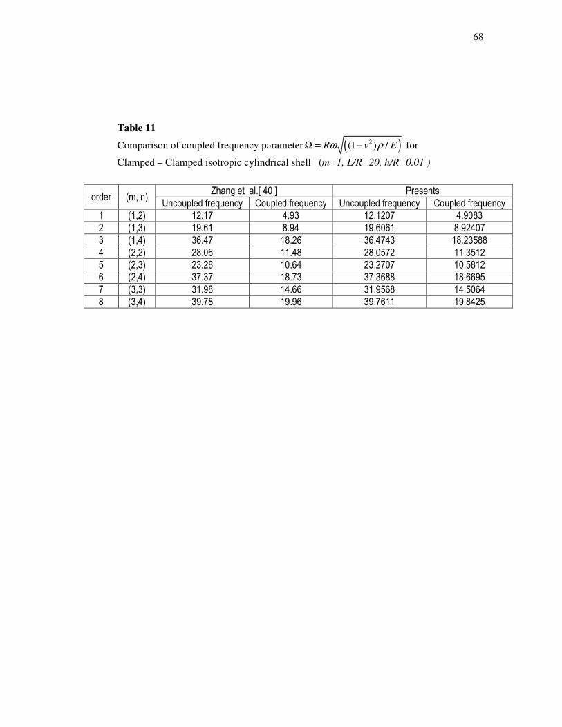
68
Table 11
Comparison of coupled frequency parameter ( )2(1 ) /R v Eω ρΩ = − for
Clamped – Clamped isotropic cylindrical shell (m=1, L/R=20, h/R=0.01 )
order (m, n) Zhang et al.[ 40 ] Presents
Uncoupled frequency Coupled frequency Uncoupled frequency Coupled frequency
1 (1,2) 12.17 4.93 12.1207 4.9083
2 (1,3) 19.61 8.94 19.6061 8.92407
3 (1,4) 36.47 18.26 36.4743 18.23588
4 (2,2) 28.06 11.48 28.0572 11.3512
5 (2,3) 23.28 10.64 23.2707 10.5812
6 (2,4) 37.37 18.73 37.3688 18.6695
7 (3,3) 31.98 14.66 31.9568 14.5064
8 (3,4) 39.78 19.96 39.7611 19.8425

69
Table 12 Variation of natural frequencies (Hz) with the circumferential wave number for
type I FGM cylindrical shell for simply supported-simply supported boundary
condition (m=1; L=20; R=1; h=0.002)
n N=0.3 N=0.7 N=1 N=3 N=15 N=25
1 13.0380 13.1537 13.2110 13.3768 13.5046 13.5212
2 4.4159 4.4544 4.4736 4.5301 4.57536 4.58145
3 4.0940 4.1301 4.14783 4.1996 4.24432 4.2509
4 6.9390 7.0020 7.03249 7.1195 7.19373 7.2049
5 11.0868 11.1884 11.2372 11.3759 11.4932 11.5109
6 16.2317 16.3809 16.4525 16.6554 16.8264 16.8522
7 22.3293 22.5347 22.6332 22.9124 23.1471 23.1825
8 29.3702 29.6406 29.7702 30.1373 30.4457 30.4922
9 37.3520 37.6959 37.8608 38.3276 38.7197 38.7788
10 46.2737 46.6999 46.9042 47.4825 47.9681 48.0412

70
Table 13 Variation of natural frequencies (Hz) with the circumferential wave number for
type I FGM cylindrical shell for simply Clamped-simply supported boundary condition
( m=1; L=20; R=1; h=0.002 )
n N=0.3 N=0.7 N=1 N=3 N=15 N=25
1 20.08594 20.1944 20.2823 20.5366 20.7327 20.7582
2 6.73355 6.7650 6.79432 6.8799 6.94768 6.9566
3 4.772763 4.7888 4.80927 4.8696 4.92129 4.92883
4 7.11455 7.1439 7.17485 7.2638 7.3401 7.35173
5 11.17814 11.2298 11.2787 11.4181 11.5363 11.5542
6 16.31987 16.3986 16.4702 16.6734 16.8449 16.8708
7 22.43519 22.5453 22.6438 22.9231 23.1583 23.1937
8 29.50262 29.6487 29.7783 30.1455 30.5433 30.5008
9 37.51646 37.7031 37.8679 38.3349 38.7272 38.7863
10 46.47487 46.7066 46.9109 47.4893 47.9751 48.0483

71
Table 14 Variation of natural frequencies (Hz) with the circumferential wave number for
type I FGM cylindrical shell for simply Clamped-Clamped boundary condition
(m=1; L=20; R=1; h=0.002)
n N=0.3 N=0.7 N=1 N=3 N=15 N=25
1 28.2391 28.4875 28.6131 28.9654 29.1110 292838
2 9.5232 9.60700 9.64867 9.7702 9.8525 9.87809
3 5.7421 5.7918 5.81661 5.8898 5.9493 5.96039
4 7.3264 7.3918 7.42369 7.5160 7.59526 76.0757
5 11.1999 11.3018 11.3509 11.4913 11.6108 11.6290
6 16.2783 16.4274 16.4990 16.7027 16.8750 16.9010
7 22.3558 22.5611 22.6596 22.9392 23.1749 23.2104
8 29.389 29.6599 29.7895 30.1569 30.4661 30.5127
9 37.36 37.7124 37.8773 38.3444 38.7370 38.7962
10 46.28 46.7152 46.9195 47.4980 47.9841 48.0572

72
Table15 Variation of natural frequencies (Hz) with the circumferential wave number for
type II FGM cylindrical shell for simply supported-simply supported boundary
condition(m=1; L=20; R=1; h=0.002 )
n N=0.3 N=0.7 N=1 N=3 N=15 N=25
1 13.3898 13.2690 13.2110 13.0502 12.9327 12.9184
2 4.53913 4.4989 4.47947 4.4246 4.3829 4.37743
3 4.21197 4.1741 4.15623 4.1059 4.06462 4.06059
4 7.13463 7.0687 7.0379 6.9535 6.8851 6.88038
5 11.3962 11.2901 11.2407. 11.1062 10.9982 10.9915
6 16.6831 16.5272 16.4549 16.2581 16.1008 16.0914
7 22.9492 22.7345 22.6349 22.3644 22.1483 22.1357
8 30.1850 29.9024 29.7713 29.4156 29.1317 29.1152
9 38.3877 38.0283 37.8615 37.4092 37.0483 37.0275
10 47.5566 47.1112 46.9046 46.3442 45.8973 45.8715

73
Table 16 Variation of natural frequencies (Hz) with the circumferential wave number for
type II FGM cylindrical shell for Clamped-simply supported boundary condition
(m=1; L=20; R=1; h=0.002 )
n N=0.3 N=0.7 N=1 N=3 N=15 N=25
1 20.5566 20.3712 20.2824 20.0357 19.8554 19.8334
2 6.8913 6.8299 6.80031 6.71718 6.6547 6.64671
3 4.8846 4.84132 4.82059 4.76194 4.71417 4.70878
4 7.2812 7.21453 7.18325 7.09692 7.02647 7.02106
5 11.4400 11.3338 11.2843 11.1492 11.0403 11.0332
6 16.7023 16.5464 16.4740 16.2770 16.1191 16.1094
7 22.9609 22.7462 22.6466 22.3759 22.1594 22.1466
8 30.1939 29.9114 29.7803 29.4244 29.1402 29.1236
9 38.3956 38.0361 37.8694 37.4169 37.0558 37.0348
10 47.5639 47.1185 46.9119 46.3514 45.9043 45.8784

74
Table 17
Variation of natural frequencies (Hz) with the circumferential wave number for
type II FGM cylindrical shell for Clamped-Clamped boundary condition
(m=1; L=20; R=1; h=0.002 )
n N=0.3 N=0.7 N=1 N=3 N=15 N=25
1 28.9996 28.7384 28.6132 28.2655 28.0114 27.9803
2 9.7843 9.6968 9.65474 9.53680 9.4490 9.37800
3 5.9072 5.8551 5.83010 5.75893 5.7018 5.69481
4 7.5361 7.46765 7.4354 7.34579 7.27231 7.26605
5 11.5152 11.4086 11.3589 11.2228 11.1126 11.1050
6 16.7330 16.5771 16.5046 16.3072 16.1485 16.1386
7 22.9780 22.7634 22.6637 22.3928 22.1758 22.1628
8 30.2061 29.9237 29.7926 29.4365 29.1519 29.1351
9 38.4058 38.0464 37.8796 37.4269 37.0655 37.0444
10 47.5732 47.1278 46.9212 46.3605 45.9132 45.8872

75
Table18 Variation of natural frequencies (Hz) with the circumferential wave number for
type III FGM cylindrical shell for simply supported-simply supported boundary
condition (m=1; L=20; R=1; h=0.002 )
n N=0.3 N=0.7 N=1 N=3 N=15 N=25
1 13.7339 13.898 13.9852 14.2602 14.4996 14.5327
2 4.65703 4.71527 4.74622 4.8429 4.91833 4.9271
3 4.30696 4.36119 4.39547 4.5160 4.58090 4.57929
4 7.28095 7.36777 7.42720 7.6483 7.76480 7.75899
5 11.6247 11.7606 11.8552 12.2117 12.4020 12.3929
6 17.0149 17.2126 17.3507 17.8734 18.1544 18.1414
7 23.4041 23.6751 23.8649 24.5842 24.9721 24.9546
8 30.7822 31.1381 31.3876 32.3339 32.8449 32.8220
9 39.1465 39.5987 39.9159 41.1193 41.7698 41.7408
10 48.4959 49.0559 49.4488 50.9397 51.7459 51.7101

76
Table19
Variation of natural frequencies (Hz) with the circumferential wave number for
type III FGM cylindrical shell for simply Clamped-simply supported boundary
condition
(m=1; L=20; R=1; h=0.002 )
n N=0.3 N=0.7 N=1 N=3 N=15 N=25
1 21.0851 21.3379 21.4716 21.8944 22.2624 22.3133
2 7.07044 7.15762 7.2036 7.34711 7.46450 7.47950
3 5.0014 5.06559 5.1039 5.2333 5.3080 5.30889
4 7.43450 7.52465 7.5852 7.8078 7.92448 7.9188
5 11.6717 11.8092 11.9044 12.2614 12.4507 12.4415
6 17.0362 17.2348 17.3733 17.8963 18.1764 18.1632
7 23.4175 23.6892 23.8792 24.5988 24.9860 24.9683
8 30.7926 31.1491 31.3988 32.3453 32.8558 32.8327
9 39.1556 39.6084 39.9257 41.1294 41.7795 41.7504
10 48.5045 49.0649 49.4579 50.9490 51.7550 51.7191

77
Table 20 Variation of natural frequencies (Hz) with the circumferential wave number for
type III FGM cylindrical shell for simply Clamped-Clamped boundary condition
(m=1; L=20; R=1; h=0.002 )
n N=0.3 N=0.7 N=1 N=3 N=15 N=25
1 29.7457 30.1030 30.2920 30.8894 31.4094 31.4813
2 10.0382 10.1608 10.2255 10.4275 10.5965 10.6189
3 6.05462 6.13252 6.1769 6.3221 6.41355 6.41801
4 7.69987 7.79488 7.85727 8.0826 8.20105 8.19611
5 11.7514 11.8911 11.9871 12.3448 12.5335 12.5242
6 17.0697 17.2696 17.4086 17.9320 18.2112 18.1978
7 23.4368 23.7094 23.8997 24.6196 25.0061 24.9881
8 30.8067 31.1639 31.4138 32.3606 32.8705 32.8473
9 39.1675 39.6208 39.9384 41.1423 41.7920 41.7627
10 48.5153 49.0762 49.4694 50.960 51.7665 51.7304

78
Table 21 Variation of natural frequencies (Hz) with the circumferential wave number for
type IV FGM cylindrical shell for simply supported-simply supported boundary
condition (m=1; L=20; R=1; h=0.002 )
n N=0.3 N=0.7 N=1 N=3 N=15 N=25
1 14.2825 14.0761 13.9842 13.7499 13.5957 13.5772
2 4.8349 4.7625 4.73008 4.64866 4.60180 4.59728
3 4.4828 4.4092 4.37160 4.27168 4.24295 4.24740
4 7.6033 7.4787 7.41173 7.22771 7.18038 7.1912
5 12.1512 11.9533 11.8460 11.5488 11.4711 11.4887
6 17.7919 17.5030 17.3460 16.9099 16.7947 16.8202
7 24.4768 24.0798 23.8639 23.2636 23.1041 23.1390
8 32.1958 31.6739 31.3900 30.6002 30.3898 30.4356
9 40.9462 40.2827 39.9216 38.9170 38.6490 38.7072
10 50.7271 49.9052 49.4579 48.2133 47.8810 47.9529

79
Table 22 Variation of natural frequencies (Hz) with the circumferential wave number for type IV
FGM cylindrical shell for Clamped-simply supported boundary condition
(m=1; L=20; R=1; h=0.002)
n N=0.3 N=0.7 N=1 N=3 N=15 N=25
1 21.9286 21.6114 21.4701 21.1097 20.8727 20.8441
2 7.34350 7.23516 7.1869 7.06554 6.9911 6.98304
3 5.19670 5.11265 5.0713 4.96398 4.92739 4.92999
4 7.7558 7.62828 7.56041 7.37549 7.32775 7.3384
5 12.1949 11.9957 11.8881 11.5908 11.5138 11.5314
6 17.8099 17.5202 17.3630 16.9270 16.8124 16.8380
7 24.4871 24.0896 23.8736 23.2733 23.1144 23.1494
8 32.2035 31.6812 31.3972 30.6074 30.3975 30.4434
9 40.9528 40.2891 39.9279 38.9233 38.6557 38.7139
10 50.7333 49.9111 49.4638 48.2191 47.8871 47.9592

80
Table 23 Variation of natural frequencies (Hz) with the circumferential wave number for
type IV FGM cylindrical shell for Clamped-Clamped boundary condition
(m=1; L=20; R=1; h=0.002 )
n N=0.3 N=0.7 N=1 N=3 N=15 N=25
1 30.9378 30.4895 30.2898 29.7805 29.4454 29.4050
2 10.4291 10.2763 10.2085 10.0372 9.92931 9.91697
3 6.28470 6.1851 6.13785 6.0172 5.96809 5.96816
4 8.02325 7.8911 7.8218 7.63498 7.58543 7.59550
5 12.2713 12.0704 11.9622 11.6646 11.5880 11.6057
6 17.8396 17.5490 17.3915 16.9554 16.8416 16.8673
7 24.5028 24.1047 23.8885 23.2882 23.1300 23.1651
8 32.2142 31.6915 31.4073 30.6175 30.408 30.4542
9 40.9616 40.2975 39.9362 38.9316 38.6644 38.72280
10 50.7412 49.9189 49.4714 48.2267 47.8950 47.9672

81
Table 24
Variation of natural frequencies (Hz) with the circumferential wave number for
type V FGM cylindrical shell for simply supported-simply supported boundary
condition
(m=1; L=20; R=1; h=0.002 )
n N=0.3 N=0.7 N=1 N=3 N=15 N=25
1 13.1819 13.4414 13.5807 14.0310 14.4360 14.4930
2 4.46704 4.5565 4.60490 4.7610 4.89494 4.91247
3 4.12572 4.2095 4.25978 4.4338 4.5552 45.6287
4 6.9751 7.1145 7.20150 7.51207 7.7216 7.7313
5 11.1377 11.3589 11.4977 11.9967 12.3340 12.3493
6 16.3030 16.6260 16.8291 17.5602 18.0554 18.0780
7 22.4254 22.8692 23.1484 24.1544 24.8364 24.8676
8 29.4953 30.0787 30.4459 31.7690 32.6666 32.7077
9 37.5101 38.2518 38.7187 40.4015 41.5432 41.5956
10 46.4689 47.3876 47.9660 50.0506 51.4653 51.5303

82
Table 25
Variation of natural frequencies (Hz) with the circumferential wave number for
type V FGM cylindrical shell for Clamped-simply supported boundary condition
(m=1; L=20; R=1; h=0.002 )
n N=0.3 N=0.7 N=1 N=3 N=15 N=25
1 20.2384 20.6371 20.8510 21.5428 22.1649 22.2524
2 6.78349 6.9185 6.99116 7.22505 7.43004 7.4579
3 4.7919 4.8897 4.94641 5.13855 5.27893 52.9036
4 7.12170 7.26487 7.35337 7.6675 7.8800 7.8903
5 11.1822 11.4049 11.5443 12.0444 12.3821 12.3974
6 16.3230 16.6468 16.8502 17.5819 18.0770 18.0995
7 22.4379 22.8822 23.1617 24.1680 24.8499 24.8810
8 29.5050 30.0889 30.4562 31.7798 32.6772 32.7183
9 37.5187 38.2608 38.7278 40.4109 41.5527 41.6050
10 46.4770 47.3960 47.9745 5.00595 51.4742 51.5392

83
Table 26 Variation of natural frequencies (Hz) with the circumferential wave number for
type V FGM cylindrical shell for simply supported-simply supported boundary
condition
(m=1; L=20; R=1; h=0.002 )
n N=0.3 N=0.7 N=1 N=3 N=15 N=25
1 28.5523 29.1151 29.4172 30.3937 31.2718 31.3954
2 9.63197 9.8230 9.92562 10.2559 10.5484 10.5888
3 5.80274 5.9209 5.9876 6.20922 6.37960 6.39648
4 7.3756 7.5246 07.6157 7.9361 8.15485 8.1665
5 11.2580 11.4829 11.6232 12.1252 12.4639 12.4795
6 16.3546 16.6795 16.8834 17.6160 18.1112 18.1337
7 22.4559 22.9010 23.1808 24.1878 24.8695 24.9006
8 29.5182 30.1026 30.4702 31.7942 32.6916 32.7326
9 37.5298 38.2724 38.7396 40.4232 41.5649 41.6172
10 46.4871 47.4066 47.9853 50.0707 51.4855 51.5504

84
Table 27 Variation of natural frequencies (Hz) with the circumferential wave number for
type VI FGM cylindrical shell for simply supported-simply supported boundary
condition (m=1; L=20; R=1; h=0.002 )
n N=0.3 N=0.7 N=1 N=3 N=15 N=25
1 14.0689 13.7287 13.5798 13.2074 12.9677 12.9390
2 4.76371 4.64667 4.59513 4.4666 4.3889 4.38058
3 4.41482 4.29981 4.24489 4.1027 4.04206 4.04165
4 7.48413 7.2878 7.19146 6.9371 6.83664 6.83911
5 11.9590 11.6459 11.4914 11.0825 10.9209 10.9251
6 17.5097 17.0517 16.8256 16.2260 15.9886 15.9948
7 24.0881 23.4582 23.1472 22.3222 21.9950 22.0034
8 31.6842 30.8559 30.4468 29.3615 28.9307 28.9417
9 40.2953 39.2421 38.7219 37.3414 36.7933 36.8073
10 49.9205 48.6158 47.9713 46.2611 45.5819 45.5991

85
Table 28
Variation of natural frequencies (Hz) with the circumferential wave number for type VI
FGM cylindrical shell for Clamped-simply supported boundary condition
(m=1; L=20; R=1; h=0.002 )
n N=0.3 N=0.7 N=1 N=3 N=15 N=25
1 21.6009 21.0783 20.8496 20.2775 19.9092 19.8652
2 7.23491 7.05840 6.9810 6.7882 6.6680 6.65434
3 5.1192 4.98750 4.9260 4.76913 4.6959 4.69323
4 7.63528 7.4350 7.3372 7.0803 6.9778 6.9798
5 12.0026 11.6881 11.5332 11.1236 10.9619 10.9661
6 17.5278 17.0691 16.8427 16.2429 16.0057 16.0119
7 24.0985 23.4683 23.1571 22.3319 22.0049 22.0134
8 31.6920 30.8634 30.4542 29.3687 28.9382 28.9492
9 40.3020 39.2486 38.7282 37.3476 36.7997 36.8137
10 49.9268 48.6219 47.9773 46.2669 45.5879 45.6051

86
Table 29 Variation of natural frequencies (Hz) with the circumferential wave number for
type VI FGM cylindrical shell for simply supported-simply supported boundary
condition (m=1; L=20; R=1; h=0.002 )
n N=0.3 N=0.7 N=1 N=3 N=15 N=25
1 30.4758 29.7380 29.4152 28.6075 28.0875 28.0254
2 10.2744 10.0246 9.9152 9.6426 9.4704 9.4503
3 6.19196 6.03489 5.96319 5.7819 5.68962 5.6836
4 7.89979 7.69296 7.5927 7.3309 7.2243 7.22556
5 12.0787 11.7620 11.6063 11.1954 11.0331 11.0372
6 17.5576 17.0979 16.8712 16.2709 16.0338 16.0400
7 24.1144 23.4835 23.1721 22.3467 22.0199 22.0285
8 31.7029 30.8739 30.4645 29.3788 28.9485 28.9596
9 40.3109 39.2571 38.7367 37.3559 36.8082 36.8222
10 49.9349 48.6296 47.9849 46.2743 45.5955 45.6128

87
Table 30
M1 M2 E1/E2 V1/ V2 P1/ P1
Type I Stainless steel Nickel 1.0131 >1 1.0250 >1 0.9175 <1
TypeII Nickel Stainless steel 0.9871 <1 0.9756 <1 1.0899 >1
TypeIII Stainless steel Zirconia 1.2364 >1 1.0663 >1 1.4326 >1
TypeIV Zirconia Stainless steel 0.8088 <1 0.9378 <1 0.6980 <1
TypeV Nickel Zirconia 1.2204 >1 1.0403 >1 1.5614 >1
TypeVI Zirconia Nickel 0.8194 <1 0.9613 <1 0.6404 <1

88
Table 31 Coupled and uncoupled frequency of FGM circular cylindrical shell of Type I for
simply supported- simply supported boundary condition
N=0.3 N=1 N=5 N=10
m N Un coupled
Coupled Ratio Un coupled
Coupled Ratio Un coupled
Coupled Ratio Un coupled
Coupled Ratio
1 2 4.4160 0.9031 4.8898 4.4737 0.9049 4.9439 4.5498 0.9076 5.0130 4.5683 0.9083 5.0295
3 4.0940 0.9599 4.2650 4.1478 0.9620 4.3116 4.2183 0.9650 4.3713 4.2368 0.9661 4.3855
4 6.9391 1.8234 3.8056 7.0325 1.8284 3.8463 7.1505 1.8340 3.8989 7.1812 1.8361 3.9111
5 11.0868 3.1982 3.4666 11.2372 3.2077 3.5032 11.4249 3.2179 3.5504 11.4734 3.2216 3.5614
2 2 16.6282 3.3988 4.8924 16.8480 3.4062 4.9463 17.1326 3.4158 5.0157 17.1995 3.4181 5.0319
3 8.7166 2.0419 4.2689 8.8299 2.0462 4.3153 8.9807 2.0527 4.3751 9.0179 2.0546 4.3891
4 8.2623 2.1697 3.8080 8.3704 2.1748 3.8488 8.5130 2.1820 3.9015 8.5503 2.1847 3.9137
5 11.4831 3.3109 3.4683 11.6366 3.3201 3.5049 11.8327 3.3312 3.5521 11.8839 3.3352 3.5632
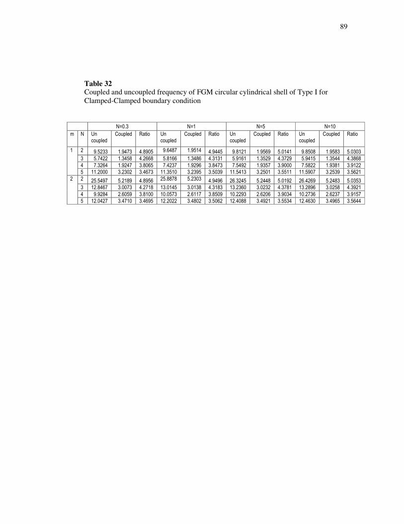
89
Table 32 Coupled and uncoupled frequency of FGM circular cylindrical shell of Type I for
Clamped-Clamped boundary condition
N=0.3 N=1 N=5 N=10
m N Un coupled
Coupled Ratio Un coupled
Coupled Ratio Un coupled
Coupled Ratio Un coupled
Coupled Ratio
1 2 9.5233 1.9473 4.8905 9.6487 1.9514 4.9445 9.8121 1.9569 5.0141 9.8508 1.9583 5.0303
3 5.7422 1.3458 4.2668 5.8166 1.3486 4.3131 5.9161 1.3529 4.3729 5.9415 1.3544 4.3868
4 7.3264 1.9247 3.8065 7.4237 1.9296 3.8473 7.5492 1.9357 3.9000 7.5822 1.9381 3.9122
5 11.2000 3.2302 3.4673 11.3510 3.2395 3.5039 11.5413 3.2501 3.5511 11.5907 3.2539 3.5621
2 2 25.5497 5.2189 4.8956 25.8878 5.2303 4.9496 26.3245 5.2448 5.0192 26.4269 5.2483 5.0353
3 12.8467 3.0073 4.2718 13.0145 3.0138 4.3183 13.2360 3.0232 4.3781 13.2896 3.0258 4.3921
4 9.9284 2.6059 3.8100 10.0573 2.6117 3.8509 10.2293 2.6206 3.9034 10.2736 2.6237 3.9157
5 12.0427 3.4710 3.4695 12.2022 3.4802 3.5062 12.4088 3.4921 3.5534 12.4630 3.4965 3.5644

90
Table 33
Coupled and uncoupled frequency of FGM circular cylindrical shell of Type I for
simply supported-Clamped boundary condition
N=0.3 N=1 N=5 N=10
m N Un coupled
Coupled Ratio Un coupled
Coupled Ratio Un coupled
Coupled Ratio Un coupled
Coupled Ratio
1 2 6.7063 1.3714 4.8901 6.7943 1.3742 4.9442 6.9096 1.3782 5.0135 6.9372 1.3792 5.0299
3 4.7475 1.1129 4.2659 4.8093 1.1153 4.3121 4.8914 1.1188 4.3720 4.9127 1.1201 4.3859
4 7.0802 1.8603 3.8059 7.1749 1.8652 3.8467 7.2957 1.8710 3.8994 7.3273 1.8732 3.9116
5 11.1283 3.2099 3.4669 11.2788 3.2193 3.5035 11.4675 3.2296 3.5507 11.5164 3.2334 3.5617
2 2 20.8725 4.2651 4.8938 21.1485 4.2744 4.9477 21.5055 4.2864 5.0171 21.5893 4.2892 5.0334
3 10.6479 2.4935 4.2703 10.7867 2.4988 4.3168 10.9705 2.5067 4.3765 11.0155 2.5089 4.3906
4 8.9985 2.3625 3.8089 9.1157 2.3679 3.8497 9.2714 2.3758 3.9024 9.3118 2.3787 3.9147
5 11.7215 3.3791 3.4688 11.8775 3.3882 3.5055 12.0781 3.3997 3.5527 12.1307 3.4039 3.5638

91
Table 34 Coupled and uncoupled frequency of FGM circular cylindrical shell of Type II for
simply supported-simply supported boundary condition
N=0.3 N=1 N=5 N=10
m n Un coupled
Coupled Ratio Un coupled
Coupled Ratio Un coupled
Coupled Ratio Un coupled
Coupled Ratio
1 2 4.5391 0.9079 4.9996 4.4795 0.9061 4.9437 4.4063 0.9034 4.8775 4.3893 0.9027 4.8624
3 4.2120 0.9661 4.3598 4.1562 0.9640 4.3114 4.0885 0.9610 4.2544 4.0715 0.9599 4.2416
4 7.1346 1.8348 3.8885 7.0380 1.8298 3.8463 6.9247 1.8242 3.7960 6.8966 1.8222 3.7848
5 11.3963 3.2183 3.5411 11.2407 3.2087 3.5032 11.0607 3.1985 3.4581 11.0163 3.1949 3.4481
2 2 17.0812 3.4148 5.0021 16.8541 3.4075 4.9462 16.5808 3.3979 4.8797 16.5195 3.3956 4.8650
3 8.9629 2.0541 4.3634 8.8457 2.0499 4.3152 8.7007 2.0434 4.2580 8.6665 2.0414 4.2454
4 8.5010 2.1847 3.8912 8.3890 2.1796 3.8489 8.2519 2.1724 3.7985 8.2176 2.1697 3.7874
5 11.8096 3.3334 3.5428 11.6507 3.3241 3.5049 11.4625 3.3131 3.4598 11.4154 3.3091 3.4497

92
Table 35
Coupled and uncoupled frequency of FGM circular cylindrical shell of Type II for
Clamped-Clamped boundary condition
N=0.3 N=1 N=5 N=10
m N Un coupled
Coupled
Ratio Un coupled
Coupled Ratio Un coupled
Coupled Ratio Un coupled
Coupled Ratio
1 2 9.7844 1.9567 5.0005 9.6547 1.9526 4.9445 9.4978 1.9471 4.8779 9.4623 1.9457 4.8632
3 5.9072 1.3545 4.3612 5.8301 1.3517 4.3132 5.7344 1.3474 4.2559 5.7110 1.3459 4.2433
4 7.5361 1.9375 3.8896 7.4354 1.9326 3.8474 7.3148 1.9265 3.7969 7.2846 1.9241 3.7860
5 11.5152 3.2512 3.5418 11.3590 3.2418 3.5039 11.1764 3.2313 3.4588 11.1310 3.2275 3.4488
2 2 26.2435 5.2429 5.0055 25.8941 5.2315 4.9497 25.4747 5.2169 4.8831 25.3811 5.2135 4.8683
3 13.2048 3.0242 4.3664 13.0312 3.0177 4.3183 12.8183 3.0083 4.2610 12.7691 3.0057 4.2483
4 10.2149 2.6238 3.8932 10.0814 2.6180 3.8508 9.9160 2.6092 3.8004 9.8752 2.6061 3.7893
5 12.3883 3.4954 3.5442 12.2231 3.4862 3.5061 12.0246 3.4743 3.4610 11.9748 3.4699 3.4511

93
Table 36
Coupled and uncoupled frequency of FGM circular cylindrical shell of Type II for
simply supported- Clamped boundary condition
N=0.3 N=1 N=5 N=10
m N Un coupled
Coupled Ratio Un coupled
Coupled Ratio Un coupled
Coupled Ratio Un coupled
Coupled Ratio
1 2 6.8913 1.3783 4.9999 6.8003 1.3755 4.9439 6.6895 1.3715 4.8775 6.6643 1.3705 4.8627
3 4.8846 1.1202 4.3605 4.8206 1.1179 4.3122 4.7416 1.1144 4.2548 4.722 1.1131 4.2422
4 7.2813 1.8723 3.8890 7.1833 1.8674 3.8467 7.0672 1.8616 3.7963 7.0382 1.8594 3.7852
5 11.4401 3.2303 3.5415 11.2844 3.2209 3.5035 11.1033 3.2106 3.4583 11.0585 3.2069 3.4483
2 2 21.44 4.2849 5.0036 21.1547 4.2757 4.9477 20.8119 4.2637 4.8812 20.7352 4.2609 4.8664
3 10.9466 2.5079 4.3648 10.8031 2.5026 4.3168 10.6263 2.4948 4.2594 10.585 2.4925 4.2467
4 9.2586 2.3788 3.8921 9.1372 2.3735 3.8497 8.9875 2.3655 3.7994 8.9503 2.3627 3.7882
5 12.0564 3.4024 3.5435 11.8949 3.3932 3.5055 11.7023 3.3818 3.4604 11.654 3.3776 3.4504

94
Figures
Fig.1 Geometry of a cylindrical shell
z ,w
x, u
θ ,v
L
h
R
θ

95
V1………..
V2______
0
0.2
0.4
0.6
0.8
1
1.2
-0.5 -0.4 -0.3 -0.2 -0.1 0 0.1 0.2 0.3 0.4 0.5
z/h
Fig.2
Variation of volume fraction of resultant volume fraction of FGM with thickness
(z/h)
N= 0.3
N=0.5
N=0.8
N=1
N=2
N=3
N=5
N=0.3
N=0.5
N=o.8
N=1
N=2
N=3
N=5

96
Fig.3
Variation of the natural frequencies (Hz) against circumferential wave number (n)
For Type I for simply supported – simply supported boundary condition
N=0.3
N=0.7
N=1
N=3
N=15
N=25

97
Fig.4
Variation of the natural frequencies (Hz) against circumferential wave number (n)
For Type I for clamped – clamped boundary condition
Fig 3.2
CC
0
10
20
30
40
50
60
1 2 3 4 5 6 7 8 9 10
Circumferential wave number (n )
Nat
ura
l fr
equ
ency
(H
z)
N=0.3N=0.7N=1N=3N=15 N=25

98
Fig.5
Variation of the natural frequencies (Hz) against circumferential wave number (n)
For Type I for clamped – simply supported boundary condition
Fig 3.3
CS
0
10
20
30
40
50
60
1 2 3 4 5 6 7 8 9 10
Circumferential wave number (n)
Nat
ura
l fr
equen
cy (
Hz)
N=0.3
N=0.7
N=1
N=3
N=15
N=25

99
Fig.6
Variation of the natural frequencies (Hz) against circumferential wave number (n)
For Type II for simply supported – simply supported boundary condition
N=0.3
N=0.7
N=1
N=3
N=15
N=25

100
Fig 7
Variation of the natural frequencies (Hz) against circumferential wave number (n)
For Type II for clamped – clamped boundary condition
Fig 4.2
CC
0
10
20
30
40
50
60
1 2 3 4 5 6 7 8 9 10
Circumferential wave number ( n )
Nat
ura
l fr
equ
ency
(H
z)
N=0.3
N=0.7
N=1N=3N=15N=25
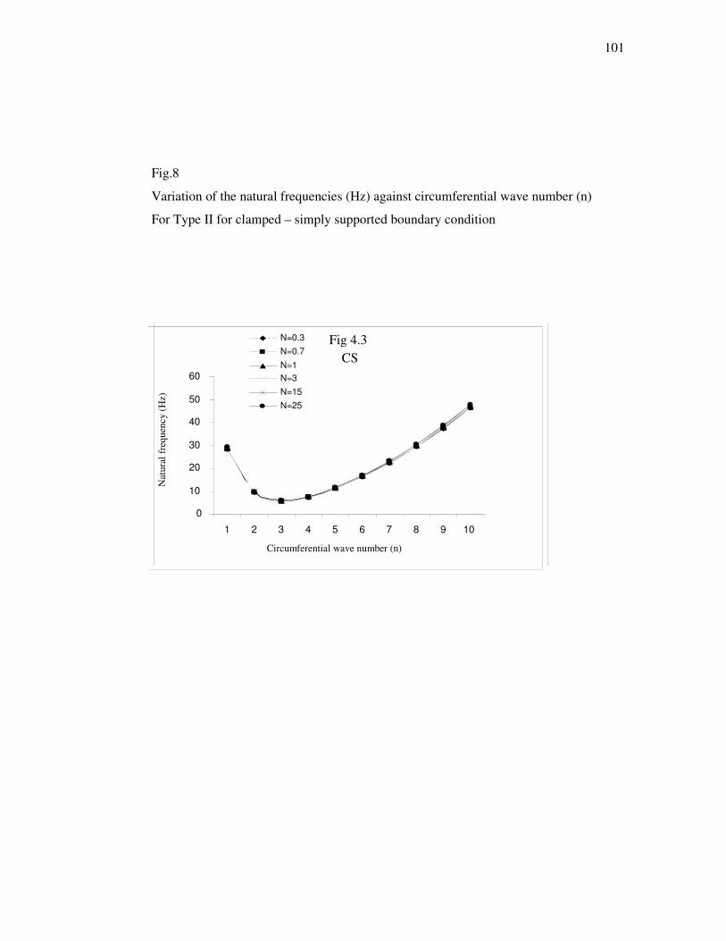
101
Fig.8
Variation of the natural frequencies (Hz) against circumferential wave number (n)
For Type II for clamped – simply supported boundary condition
Fig 4.3
CS
0
10
20
30
40
50
60
1 2 3 4 5 6 7 8 9 10
Circumferential wave number (n)
Natu
ral
freq
uen
cy (
Hz)
N=0.3
N=0.7
N=1 N=3 N=15
N=25

102
Fig.9
Variation of resultant material properties: Young’s Modulus (E) with thickness variable
(z/h) : M1 ≡ Stainless steel M2 ≡ Nickel
N=0.3
N=0.7
N=1
N=3
N=15
N=25

103
Fig 10
Variation of resultant material properties: Poisson's ratio (v) with thickness variable
(z/h) : M1 ≡ Stainless steel M2 ≡ Nickel
Fig. 5.2
3.0600E-01
3.0800E-01
3.1000E-01
3.1200E-01
3.1400E-01
3.1600E-01
3.1800E-01
3.2000E-01
-0.5 -0.3 -0.1 0.1 0.3 0.5
Thickness variable (z/h)
Pois
son's
rat
io (
v )
N=0.3 N=0.5 N=0.8 N=1 N=2 N=3 N=5

104
Fig 11
Variation of resultant material properties: Mass density (ρ ) with thickness variable
(z/h) : M1 ≡ Stainless steel M2 ≡ Nickel
Fig.5.3
7.6000E+03
7.8000E+03
8.0000E+03
8.2000E+03
8.4000E+03
8.6000E+03
8.8000E+03
9.0000E+03
-0.5 -0.3 -0.1 1 3 5
Thickness variable ( z/h)
Mass
den
sity
( ρ
) N=0.3N=0.5N=0.8N=1 N=2 N=3 N=5

105
Fig.12
Variation of resultant material properties Young’s Modulus (E) with thickness variable
(z/h) : M2 ≡ Stainless steel M1 ≡ Nickel
N=0.3
N=0.7
N=1
N=3
N=15
N=25

106
Fig.13
Variation of resultant material properties: Poisson's ratio (v) with thickness variable
(z/h): M2 ≡ Stainless steel M1 ≡ Nickel
3.0500E-01
3.1000E-01
3.1500E-01
3.2000E-01
-0.5 -0.3 -0.1 1 3 5
Normalized radial distance (z/h)
Pois
son’s
rat
io (
v)
N=0.3 N=0.5 N=0.8 N=1 N=2 N=3 N=5

107
Fig.14
Variation of resultant material properties Mass density (ρ ) with thickness variable
(z/h) M2 ≡ Stainless steel M1 ≡ Nickel
7.6000E+03
7.8000E+03 8.0000E+03
8.2000E+03
8.4000E+03
8.6000E+03 8.8000E+03
9.0000E+03
-0.5 -0.3 -0.1 1 3 5
Normalized radial distance (z/h)
N=0.3N=0.5N=0.8N=1N=2N=3N=5
Mass
den
sity
(ρ)

108
Fig 15 Variation of Coupled frequency (Hz) with circumferential number (n) of FGM
circular cylindrical shell of Type I for simply supported-simply supported boundary
condition
SS-SS
0
0.5
1
1.5
2
2.5
3
3.5
1 2 3 4
Circumferential wave number (n)
Co
up
led
Fre
qu
en
cy (
Hz)
N=0.3
N=0.7
N=1
N=5
N=10

109
C-C
0
0.5
1
1.5
2
2.5
3
3.5
1 2 3 4
Circumferential wave number (n)
Co
up
led
Fre
qu
en
cy
(H
z)
N=0.3
N=0.7
N=1
N=5
N=10
Fig 16 Variation of Coupled frequency (Hz) with circumferential number (n) of FGM
circular cylindrical shell Type I for Clamped-Clamped boundary condition.

110
Fig. 17 Variation of Coupled frequency (Hz) with circumferential number (n) of FGM
circular cylindrical shell Type I for simply supported -clamped boundary
condition.
SS-C
0
0.5
1
1.5
2
2.5
3
3.5
1 2 3 4
Circumferential wave number (n)
Co
up
led
Fre
qu
en
cy (
Hz)
N=0.3
N=0.7
N=1
N=5
N=10
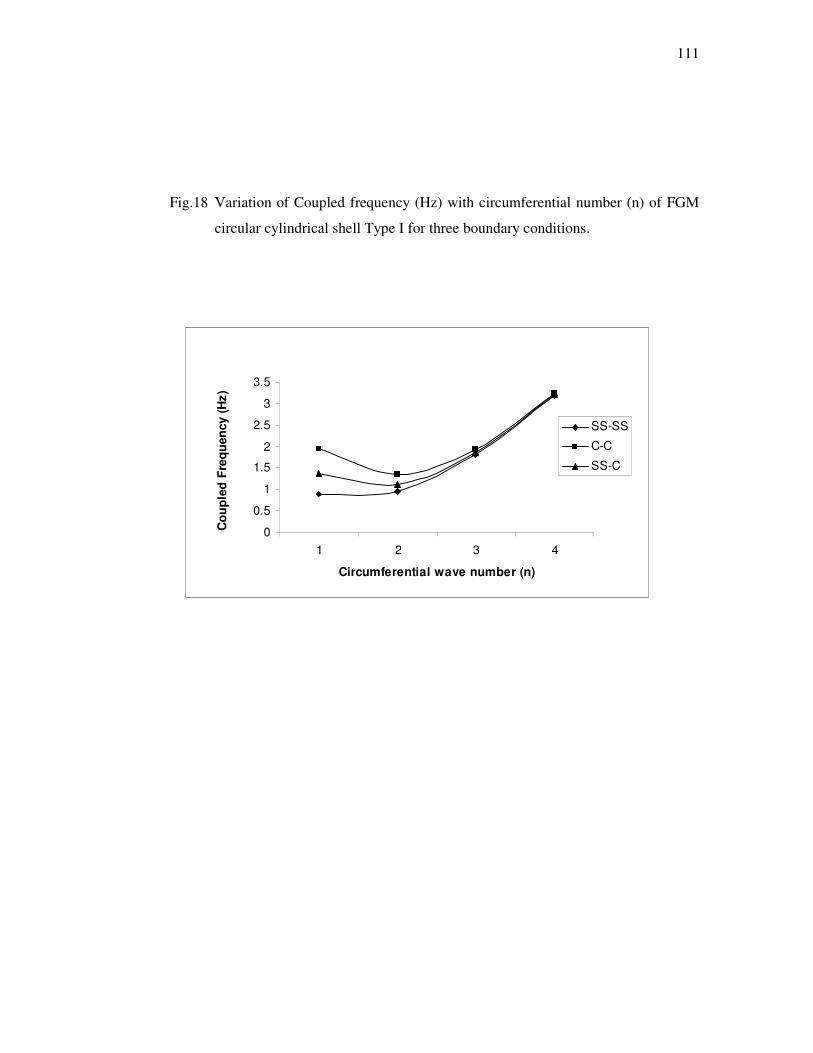
111
Fig.18 Variation of Coupled frequency (Hz) with circumferential number (n) of FGM
circular cylindrical shell Type I for three boundary conditions.
0
0.5
1
1.5
2
2.5
3
3.5
1 2 3 4
Circumferential wave number (n)
Co
up
led
Fre
qu
en
cy (
Hz)
SS-SS
C-C
SS-C

112
Fig .19 Variation of Coupled frequency (Hz) with Volume fraction exponents (N)
of FGM circular cylindrical shell of Type I and Type II for simply supported-
simply supported boundary condition
.
0.898
0.9
0.902
0.904
0.906
0.908
0.91
1 2 3 4 5 6
Volume fraction exponents (N)
Co
up
led
Fre
qu
en
cy (
Hz)
Type I
Type II

113
Appendix A
2 3 22
11 11 662 2
m R L nT A A B
L R
π πω= + −
[ ]2
661212 12 66
2
2
BBm n RT A A
R R
π= − + + +
[ ]22 2 22
6612 1113 12 2
2
2
B nn B m R BmT A
R R L
ππ= − + + +
2 3 2266 66 22 22 22
22 66 2
22
2 2 2
A R D A B Dm n LT B B
L R R R R
π πω
= − + + + + + −
2 3 3
6612 12 22 2223 66 22 2222 2 2 2
DB D B Dm n n L n LT B A B
L R R R R R R
π π π = + + + + + + +
[ ]2 2 22 2 3 2 2 3
222 11 2233 12 66 22 122 2
22 2 2
n D m R D L Am n n L mT D D B B B
LR R R L L R
π ππ π πω
= + + + + + + −

114
Appendix B
22 2
11 11 662( )
m T
nT K A A h
Rω ρ= + −
[ ]661212 12 66
2( )mi K n BB
T A AR R R
= − + + +
]2
21213 11 66 122
( ) (2 )m m
A nT i K K B B B
R R
= + + +
22 266 66 22 22
22 66 222 2 2
4 4 2( )m T
B D B DnT K A A h
R R R R Rω ρ
= + + + + + −
32 12 66 12 66 22 22
23 22 222 2 3
4( )m
B B D D B Dn nT n K A B
R R R R R R
+ + = + + + + +
[ ]2 2 22
2 2 222 12 2233 12 66 22 112 3 2
( ) 22 2 ( ) ( )m
m m T
K n n D B AnT D D B K K D h FL
R R R R Rω ρ
= + + + + + + − +