Embed Size (px)
Citation preview

1
Small Turbine Engine Testing: Evaluate New Design Technologies
Replicate Failure in Fielded Components
Laboratory Group
http://Gas-Turbine-Testing.com

2
Presentation Outline
Current Conditions of Engine Testing
Technology Need – Filling the Gap Between Engine Design and Full Scale Testing
Small Turbine Testing Method & Characterization
Failure Mechanisms Replicated Using Small Turbine Testing
Developing Acceptance Test for Corrosion Induced Cracking
Capabilities & Benefits of Small Turbine Testing

3
Current Conditions of Engine Testing
Full scale gas turbine engine testing is expensive & time consuming
Testing to failure is seldom performed on full scale engines
Testing to failure is needed to fully assess the fatigue durability of components
Other conventional testing methods used early in design process do not replicate the actual environmental conditions produced in operational engines
Today’s conditions leave a gap between conventional testing methods used during the design process and expensive full
scale testing

4
Filling the Gap Between Engine Design and Full Scale Testing
Need for a cost effective testing method that allows:
Testing components to failure; multiple times
Assess the durability of components in realistic
operating environment
Timely test turn around & acquisition of data
Small engine tests produces component failures in realistic operating conditions and tests them to failure multiple times
quickly and inexpensively

5
Small Turbine Engine Testing
Monitor & acquire data from operating turbine
Reproduce realistic environmental conditions
Successfully test multiple failure mechanisms
Compare & validate scaled turbine test data with full scale engine testing results
Reproduce & effectively measure realistic turbine engine environmental conditions

6
Example Small Turbine Engine Specifications
• Burner temperature 1700F
• Uses 12 gallons per hour of fuel
• 5.1” diameter
• 112,000 RPM at max
• Axial flow, integrally bladed,
INCO-713 turbine rotor
Realistic environment, fast turn around & cost efficient

7
Full Characterization of Small Turbine Engine
Rotating thermocouples
Strain gages
Static thermocouples
Pressure probes
Small turbine testing is fully instrumented
8
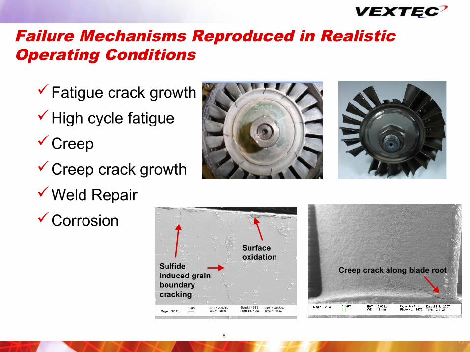
Failure Mechanisms Reproduced in Realistic Operating Conditions
Fatigue crack growth
High cycle fatigue
Creep
Creep crack growth
Weld Repair
Corrosion
Creep crack along blade rootSulfide induced grain boundary cracking
Surface oxidation

9
Developing an Acceptance Test for Corrosion Damage

10
Issue Identification
Air Force field issues with corrosion lead to HCF failures in steel compressor blades
HCF failure results from crack initiation in corrosion pit
Multiple compressor stages exhibit corrosion
Prior efforts to reproduce corrosion in lab environment were unsuccessful
Objective is to replicate field corrosion under realistic operation conditions utilizing small turbine

11
Testing Approach Experience demonstrates that the free turbine application
best meets the testing objectives
Starting point - USAF provided full scale engine performance
Test stand consist of four major sub systems– Gas generator
– Rotor with full size blades
– Drive system
– Air handling/ contaminate system
Gas Generator
Variable pressure bleed
Forced cooling Air
Contaminate System
Rotor Blade assembly
Motor
Drive system

12
Rotor/blade attachment
• Two piece split rim design for easy assembly
• Blades spacer application allows for multiple blade spacer combination.
• Rotor designed for robust operation in adverse environment
13
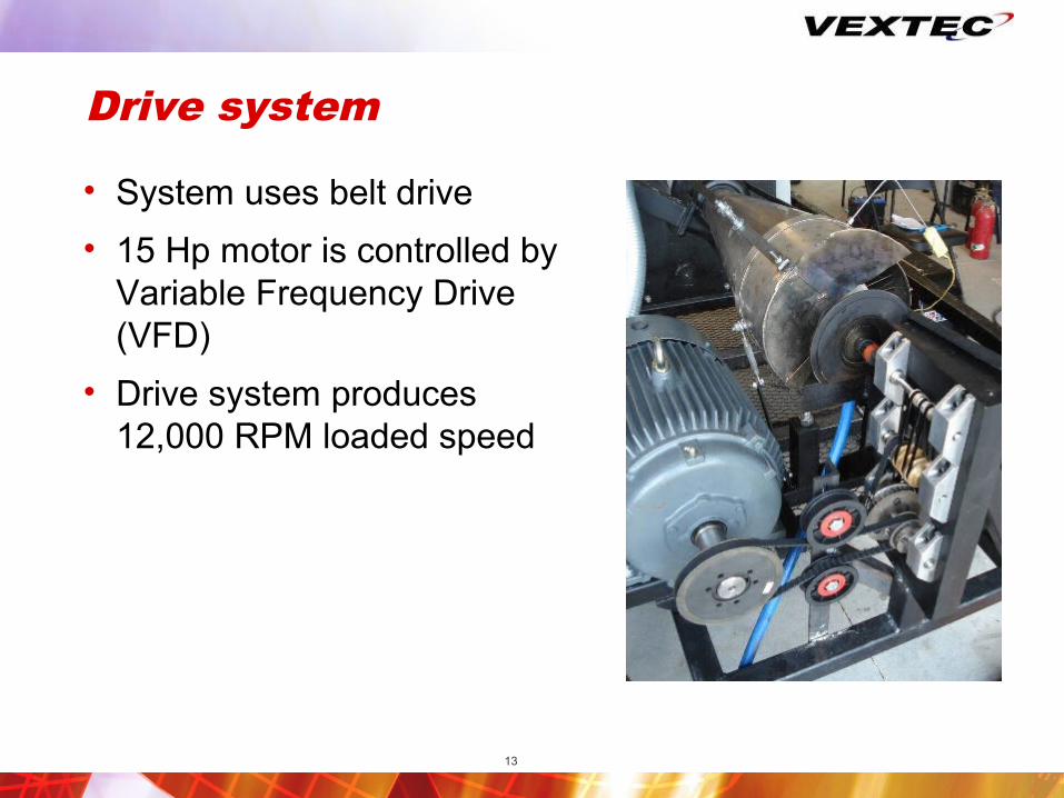
Drive system
• System uses belt drive
• 15 Hp motor is controlled by Variable Frequency Drive (VFD)
• Drive system produces 12,000 RPM loaded speed

14
Instrumentation
Compact DAQ system
Signals from instrumentation
National Instruments Modules• Two NI9239 general purpose• One NI9233 accelerometer• One NI9211 thermocouple
Gas Generator Instrumentation• K-type thermocouple - EGT• Magnetic pickup – turbine speed• PCB accelerometers – vibratory load
Test stand Instrumentation• Vane flow meter – contaminate dosing• PCB accelerometers – belt/pulley imbalance•K-type thermocouple – rotor inlet gas temperature•VFD statistics
oMotor speedoMotor load oDrive frequency

15
Small Turbine Testing for Corrosion
Blades tested - 10
Detailed blade examination – 20 hrs of operation Photo documentation
Replicas created
Total Test time – 75 hrs - Corrosion Reproduced

16
Comparison of USAF Fielded and Small Engine Tested Blades
Damage of fielded blade after 583 hours
42 µm
Damage on tested blade after 51 hours
60 µm
Test damage mechanism is same as field damage mechanism

17
Small Turbine Testing Results of USAF Corrosion Test
Reproduced blade corrosion in just 60-90 days
Crack initiates in Large
damage sites
CorrosionCorrosion HCF failureHCF failure
Sulfur drives Corrosion
Corrosion at grain
boundary
Pit size is not indicative of
damage
Confirmed corrosion is the cause of initial damage
Confirmed sulfur was primary corrosion driver
Test replicated the corrosion observed in the fielded blades

18
Capabilities & Benefits of Small Turbine Testing

19
Small Turbine Engine Capability
Accurate, realistic testing capability designed for early identification of failure issues
Reducing the amount of small scale specimen testing
Improving the validity of full scale engine testing
Accelerating design certification
Ability to bridge the gap between specimen & full scale testing for turbine engines

20
TIMELY RESULTSUseable Information in Weeks,
Not Months
COST EFFECTIVEA Fraction of the Cost of
Traditional Methods
ENGINE RELEVANTComplex Capabilities Provide
Real World Results
PRE-EMPTIVEIdentify Issues During Design
Phases, Prevent Fielded Failures
Benefits of Small Turbine Engine
21
VEXTEC Laboratory Group Contact Info
• http://Gas-Turbine-Testing.com
• Ed Pope– 317-750-3414 / [email protected]