Embed Size (px)
Citation preview

Vertical Deflection Limit of Buried Profile-Wall HDPE Drain Pipes (abstract No. 118)
Vertical Deflection Limit of Buried Profile-Wall HDPE Drain Pipes (abstract No. 118)
PI: Dr. Teruhisa (Terry) Masada, Faculty Advisor
Co-PI: Xiao Han, Ph.D. Student
Civil Engineering DepartmentRuss College of Engineering & TechnologyOhio University, Athens, OH
10:30-12:00 October 28 (Wed.), 2015
Presentation at OTEC
Session 72Buried ConduitMechanics

2
Introduction Introduction
• Thermoplastic pipelines have been utilized extensively below the ground surface to:
• 1) Provide utility service (water, natural gas, electricity, …) to customers;
• 2) Serve as alternatives to more conventional concrete and metal culverts; and
• 3) Serve as cheaper alternatives to short-span bridges.

3
IntroductionIntroduction
• In transportation related projects, HDPE pipe culverts are becoming more common than PVC pipe culverts.
• Structural health of the underground plastic pipes is vital to the overall infrastructure asset management.
• Structural conditions of buried HDPE pipes must be evaluated during and after construction. HDPE pipes are soft and flexible. They can deform much more easily than pipes made from other materials.

4
IntroductionIntroduction
• HDPE pipes come with profiled wall sections.
(a) Straight Wall
(b) Corrugated Wall
(c) Profile Wall
(a) Straight Wall
(b) Corrugated Wall
(c) Profile Wall
Straight wall Profile wall
Corrugated Wall + Liner

5
IntroductionIntroduction
• Because they are flexible, HDPE pipes interact with surrounding soil to resist dead and live loads. Soil-Pipe Interaction
• Plastic pipes require high-quality structural soil fill (backfill) to be able to perform well.
Ohio University - Ohio Research Institute for Transportation and the Environment

6
IntroductionIntroduction
Springline
Crown
Invert
Bedding
Foundation Soil
SoilEnvelope
SoilEnvelope
Cover
Special Terms Used

7
IntroductionIntroduction
• Potentially Critical Regions Located in Pipe Cross-Section:
CrownCompressive Strain (outside wall);Tensile Strain (inside wall)
SpringlineCompressive Strain (inside wall);Tensile Strain (outside wall)Cracking; Buckling
InvertStresses/Strains are significant when pipe sits directly on rigid media (ex. bedrock.).

8
IntroductionIntroduction
• Limiting the maximum vertical deflection usually takes care of all concerns about the HDPE pipe’s structural performance.
• What will be the largest vertical deflection which can assure sound structural performance in varied field installation/service conditions for HDPE pipe culverts?
Ohio University - Ohio Research Institute for Transportation and the Environment

9
ObjectiveObjective
• The main goal of the OU study was to establishthe threshold vertical deflection values forthermoplastic pipes installed in a variety ofinstallation conditions
Ohio University - Ohio Research Institute for Transportation and the Environment

10
MethodologyMethodology
• Task 1: Literature Review• Summarize documented field performance cases for buried HDPE pipes
• Task 2: ASSHTO LRFD Design Calculations• Apply AASHTO LRFD method calculations to correlate vertical deflections to
performance limiting conditions for HDPE pipes
• Task 3: Computer Simulations• Use industry standard computer software CANDE to also correlate vertical
deflections to performance limit conditions for HDPE pipes
• Task 4: Development of Charts• Combine the results from all three tasks to draw conclusions and develop
charts concerning threshold vertical deflections for HDPE pipes
Ohio University - Ohio Research Institute for Transportation and the Environment

11
Task 1: Literature ReviewTask 1: Literature Review
• Hurd, J. O. (1985). "Field Performance of Corrugated Polyethylene Pipe Culverts in Ohio."
• Flattening occurs at vertical deflections exceeding15%.
• Wall buckling occurs at vertical deflections exceeding 25%.
• The vertical deflections of HDPE pipes without apparent flattening, buckling, and dent are less than 10%.
• The vertical deflections at the pipe joints are general slightly larger than those throughout the rest of the culvert.
Ohio University - Ohio Research Institute for Transportation and the Environment
12
Task 1: Literature ReviewTask 1: Literature Review
• There is no increase in vertical deflection after 2 to 4 years within pipes less than 10% deflection.
• Shallow cover and heavy truck traffic do not appear to be detrimental to the structural performance of pipes. Deflection appears to be built into the culverts instead of caused by highway loading.
Ohio University - Ohio Research Institute for Transportation and the Environment

13
Task 1: Literature ReviewTask 1: Literature Review
• Hashash, N., Selig, E. T. (1989). "Results of Field Measurements on Polyethylene Pipe Taken in August 1988."
• A 24-in profile-wall HDPE pipe was buried in the embankment and only loaded by soil dead load. The deflection, stress and strain are recorded with the rise of cover thickness. The maximum soil cover height was 100 ft.
• 24-in corrugated and profile HDPE pipes are installed in a trench with 5-ft depth and 6-ft width. The backfill is well-graded crushed limestone under 100% compaction. The load is soil dead load only.
Ohio University - Ohio Research Institute for Transportation and the Environment

14
Task 1: Literature ReviewTask 1: Literature Review
Height of Fill (ft)
Avg. Vertical Stress (psi)
Avg. Horizontal
Stress (psi)
Avg. Strain at Crest
(%)
Avg. Strain at Centroid
(%)
Avg. Circumferential Strain
(%)
Avg. Vertical
Deflection (%)
Avg. Horizontal Deflection
(%)2.5 2.87 2.17 0.000 0.000 0.21 0.00 0.00
15.0 6.27 6.00 0.228 0.115 0.32 N/A N/A
17.0 6.63 7.53 0.287 0.118 0.32 0.67 0.46
20.0 6.83 8.37 0.153 0.020 0.32 N/A N/A
36.0 9.23 16.17 0.218 0.097 0.38 0.97 0.40
55.0 11.27 26.83 0.271 0.264 0.47 1.58 0.51
63.0 12.67 30.23 0.442 0.292 1.06 2.27 0.68
76.0 15.93 40.47 0.775 0.718 1.15 3.22 0.59
95.0 17.67 N/A 1.455 1.149 1.26 4.02 0.64
99.0 16.83 N/A 1.662 1.333 1.30 4.04 0.61
Ohio University - Ohio Research Institute for Transportation and the Environment

15
Task 1: Literature ReviewTask 1: Literature Review
• At 95-ft soil cover, the average deflection of corrugated pipe is 3.4%, and the average deflection of profile pipe is 4.4%.
• The max. vertical deflection is 7.2%, and no local distress or structural damage observed.
Ohio University - Ohio Research Institute for Transportation and the Environment

16
Task 1: Literature ReviewTask 1: Literature Review
• Hsuan, Y.G., McGrath, T. J. (1999). NCHRP Report 429: HDPE Pipe: Recommended Material Specifications and Design Requirements. National Academy Press, Washington, D.C.
• Field performances of buried HDPE pipes in various regions of the U.S. are surveyed and presented in this report.
Ohio University - Ohio Research Institute for Transportation and the Environment

17
Task 1: Literature ReviewTask 1: Literature Review
Year Installed
Pipe Type and
Diameter
Backfill Type and Depth
Pavement Type and Thickness
Daily Traffic
Vertical Deflection
Conditions
<1985Corrugated
15 in
granular and native soil
3 ft
asphalt/
light 13.3%circumferential crack appears slip at outlet
1981Corrugated
24 in
gravel bank run ODOT 304
1 ft
asphalt15 in
light 14.6%
circumferential and longitudinal crack due to
vehicle impact and mower damage at pipe ends
1983Corrugated
24 inODOT 304
2 ftasphalt
/mediu
mmax 8.3% all good
1984Corrugated
12 in
ODOT 411 limestone
5 ft
asphalt/
light 8.3% all good
1982Corrugated
15 ingravel
4.5 ~ 6 ftasphalt15 in
light 10% all good
Ohio University - Ohio Research Institute for Transportation and the Environment

18
Task 1: Literature ReviewTask 1: Literature Review
Year Installed
Pipe Type and
Diameter
Backfill Type and Depth
Pavement Type and Thickness
Daily Traffic
Vertical Deflection
Conditions
1983Corrugated
15 inmixed
1 ftasphalt
/light 13.3% all good
1995Profile30 in
sand8 ft
unpaved/
none 10%circumferential crack;
deflection at joints
1994Profile42 in
unknown3 ft
asphalt6 in
medium
average 9.5%
circumferential crack growth from 1 to 4.5 in in
one year
Ohio University - Ohio Research Institute for Transportation and the Environment

19
Task 1: Literature ReviewTask 1: Literature Review
• Moser A. P. (2000). "Structural Performance of 42-inch (1050mm) Corrugated Smooth Interior HDPE Pipe."
• Dr. Moser conducted three tests on 42-inch diameter profile-wall HDPE pipes. The pipes were buried in the embankment constructed using a silty-sand (SM) backfill material. The compaction level was different among the three tests. The load was applied using hydraulic cylinders to simulate dead load.
Ohio University - Ohio Research Institute for Transportation and the Environment

20
Task 1: Literature ReviewTask 1: Literature Review
• Test 1. The relative compaction level on backfill was 75%.
• At 40 ft, deflection 10% and a dimpling pattern started at 3 and 9 o'clock. The center distance between dimples was about the same as the rib spacing. At 55 ft, 14.5% vertical deflection, hinging was noted at 3 and 9 o'clock. At 60 ft, 16.5% deflection, hinging was very apparent and become more pronounced at 3 and 9 o'clock. Test ended at 69 ft, 20% deflection.
Ohio University - Ohio Research Institute for Transportation and the Environment

21
Task 1: Literature ReviewTask 1: Literature Review
• Test 2. The relative compaction level on backfill was 85%.
• At 70-ft soil cover, 8.7% deflection, small dimples began to form near 3 and 9 o'clock. At 82 ft, 11% deflection, waffling pattern formed. At 110 ft, 16.5% deflection, hinging started at 4 and 9 o'clock. Test ended at 110 ft.
Ohio University - Ohio Research Institute for Transportation and the Environment

22
Task 1: Literature ReviewTask 1: Literature Review
• Test 3. The relative compaction level on backfill was 95%.
• At 110 ft, 3.5% deflection, dimpling pattern began at 3 and 9 o'clock and spread toward the top of the pipe as load increased. This pattern was like a wavy checkerboard in appearance and the beginning of localized instability. The dimpling was extremely small and would not affect the structural performance of the pipe. At 140 ft, 5.2% deflection, dimples became pronounced but were not judged to be a performance limit of the pipe. At 170 ft, 6.7% deflection, first signs of wall crushing were noted at 10 o'clock. At 225 ft, 9.4% deflection, waffling and wall crushing became more pronounced but the pipe did not fail. Test ends at 225 ft.
Ohio University - Ohio Research Institute for Transportation and the Environment

23
Task 1: Literature ReviewTask 1: Literature Review
• Sargand, S. M. and Masada, T. (2011). “Field Service Conditions of the Oldest Corrugated HDPE Pipe Culvert Under Ohio's Roadway."
• In this ASCE journal paper, the ORITE researchers reported the field conditions of a 24" diameter corrugated HDPE pipe culvert that had served under SR 145 (Noble County) under a shallow soil cover and low pH (4-5) drainage flow. The pipe was installed in 1981 under a cover of 1.0 to 1.3 ft.
Ohio University - Ohio Research Institute for Transportation and the Environment

24
Task 1: Literature ReviewTask 1: Literature Review
• Vertical Deflection Data
Ohio University - Ohio Research Institute for Transportation and the Environment
Location Along Pipeline Data Collected in 1982 Data Collected in 2004
Outlet End 0.0 0.0
Middle of Section 1 -1.5% -1.0%
End of Section 1 -5.2% -5.2%
Joint -7.3% -8.3%
Middle of Section 2 0.5% 1.0%
Inlet End 0.0 0.0
AVERAGE -2.3% -2.3%
The pipe was observed to be functioning well, with no signs ofstructural distress (wall crushing, wall buckling, cracking, …).

25
Task 2: AASHTO CalculationsTask 2: AASHTO Calculations
• The AASHTO LRFD Bridge Design Specifications (2013 Interim Revisions to the Six Edition 2012).
• The vertical deflection, combined tensile strain, combined compressive strain, and buckling strain are computed through the formulas presented in Section 12: Buried Structures and Tunnel Liners.
• The live load and load combination are set up according to Section 3: Loads and Load Factors.
• The complete assumptions of parameters and formulas are listed in "AASHTO Equations".
Ohio University - Ohio Research Institute for Transportation and the Environment

26
Task 2: AASHTO CalculationsTask 2: AASHTO Calculations
Ohio University - Ohio Research Institute for Transportation and the Environment
Scanned Wall Profile of Each HDPE Pipe Diameter

27
Task 2: AASHTO CalculationsTask 2: AASHTO Calculations
Nominal Diameter
(in)
Inside Diameter
(in)
Outside Diameter
(in)
Inner Liner Thickness
(in)
Wall Area (in2/in)
Moment of Inertia I(in4/in)
Dist. toCentroid c
(in)
12 12.15 14.45 0.035 0.217 0.035 0.43
24 24.08 27.80 0.059 0.324 0.137 0.74
30 30.00 35.10 0.059 0.378 0.277 0.86
36 36.00 41.70 0.067 0.401 0.400 1.00
42 41.40 47.70 0.070 0.458 0.572 1.21
48 47.60 53.60 0.070 0.495 0.570 1.17
60 59.50 66.30 0.070 0.578 0.860 1.32
Ohio University - Ohio Research Institute for Transportation and the Environment
General Dimensions of Each HDPE Pipe Diameter
[Comment] Above dimensions based on ADS Product Note 3.107.

28
Task 2: AASHTO CalculationsTask 2: AASHTO Calculations
Nominal Diameter
S (in)
w-crest (in)
w-liner (in)
w-valley (in)
w-web (in)
t-crest (in)
t-liner (in)
t-valley (in)
t-web (in)
12 0.787 1.181 0.591 0.984 0.079 0.039 0.098 0.098
24 1.378 2.165 0.787 1.575 0.098 0.079 0.118 0.118
30 1.575 2.559 1.181 1.969 0.118 0.079 0.197 0.177
36 2.165 2.953 0.984 1.772 0.197 0.157 0.236 0.197
42 2.362 3.543 0.984 2.362 0.157 0.118 0.197 0.197
48 2.362 3.543 1.181 2.362 0.197 0.118 0.236 0.217
60 2.756 4.134 1.378 2.756 0.236 0.157 0.256 0.256
Ohio University - Ohio Research Institute for Transportation and the Environment
Detailed Dimensions of Each HDPE Pipe Diameter
[Note] “w” = width; and “t” = thickness.
29
Task 2: AASHTO CalculationsTask 2: AASHTO Calculations
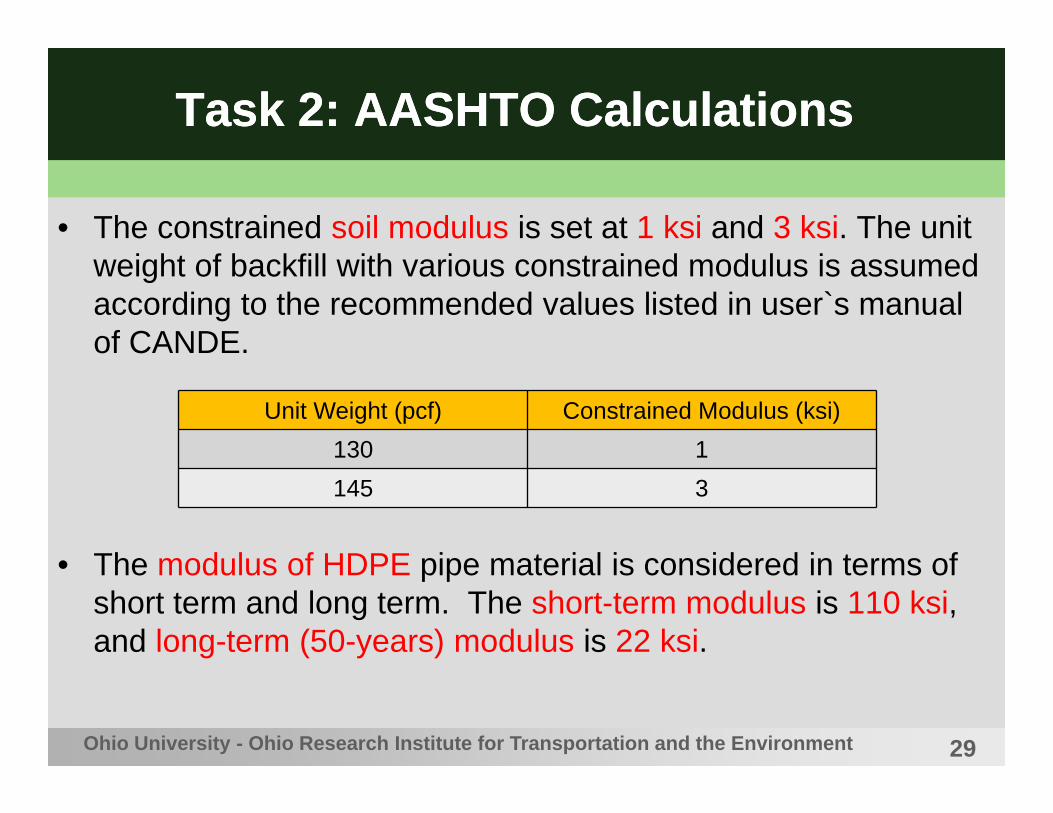
• The constrained soil modulus is set at 1 ksi and 3 ksi. The unit weight of backfill with various constrained modulus is assumed according to the recommended values listed in user`s manual of CANDE.
• The modulus of HDPE pipe material is considered in terms of short term and long term. The short-term modulus is 110 ksi, and long-term (50-years) modulus is 22 ksi.
Ohio University - Ohio Research Institute for Transportation and the Environment
Unit Weight (pcf) Constrained Modulus (ksi)130 1145 3

30
Task 2: AASHTO CalculationsTask 2: AASHTO Calculations
• AASHTO calculations are based on pipe wall strains, not on pipe wall stresses.
• The critical strains for HDPE pipe wall are 5% (tensile) and 6.15% (compressive). Calculations show that compressive strains in the pipe wall tend to reach the compressive strain limit well before tensile strains reach the tensile strain limit. Thus, a focus is placed on compressive strains in pipe wall.
• The dead load on the pipe is continuously increased to the failure of the pipe.
• The loading cases have "dead load only" as well as "dead and live loads".
Ohio University - Ohio Research Institute for Transportation and the Environment

31
Task 2: AASHTO CalculationsTask 2: AASHTO Calculations
Ohio University - Ohio Research Institute for Transportation and the Environment
Short-Term & Long-Term Strain vs. Ver. Def., Ms = 1 & 3 ksi, Dead Load Only

32
Task 2: AASHTO CalculationsTask 2: AASHTO Calculations
Ohio University - Ohio Research Institute for Transportation and the Environment
Short-Term Buckling Ratio vs. Ver. Def., Ms = 1 & 3 ksi, Dead Load Only

33
Task 2: AASHTO CalculationsTask 2: AASHTO Calculations
• When the vertical deflection is held constant, higher constrained modulus induce higher strains in the pipe wall.
• The critical vertical deflection in the long-term service condition is less than the critical vertical deflection in the short-term service condition, especially for the HDPE pipes buried in the lower modulus backfill.
• If the vertical deflections are smaller than 7.5%, the combined compressive strain will not surpass 6.15% limit in most cases, except when the pipes are buried in the 3-ksi modulus backfill material and under the long-term service condition.
• Wall buckling failure is not a concern when vertical deflections are held below 12%.
Ohio University - Ohio Research Institute for Transportation and the Environment

34
Task 2: AASHTO CalculationsTask 2: AASHTO Calculations
Ohio University - Ohio Research Institute for Transportation and the Environment
Short-Term Strain and Buckling Ratio vs. Ver. Def., Ms = 1 & 3 ksi, Dead and Live Load

35
Task 2: AASHTO CalculationsTask 2: AASHTO Calculations
• Combined compressive strain in the pipe wall never reach the strain limit even when the cover thickness is as low as 1 ft.
• When the soil cover thickness is held constant, the combined compressive strain decreases as the soil modulus increases.
• The portion of combined compressive strains caused by the live load diminishes with the soil cover. At the cover thickness of 15 ft, combined compressive strains occurred under the dead and live loads become the same to those under the dead load only.
• Under the dead and live loads, wall buckling failure mode is not a concern even at a cover thickness of 1 ft.
Ohio University - Ohio Research Institute for Transportation and the Environment

36
Task 2: ValidationsTask 2: Validations
Ohio University - Ohio Research Institute for Transportation and the Environment
Sargand, S. M. and Masada, T. (2011). “Field Service Conditions of the Oldest Corrugated HDPE Pipe Culvert Under Ohio's Roadway."
A 24-in diameter corrugated HDPE pipe had served State Route 145 (Noble County) from 1981. The pipe was installed under a cover of 1 to 1.3 ft, and the constrained modulus of soil is estimated to be around 1 ksi. The pipe was subjected to the dead and live loads. The vertical deflection was 8.3% in 2004. No overstraining/no buckling was observed.
Based on AASHTO calculation`s results, the vertical deflection of 24-in diameter HDPE pipe under live load is 8.16%, and max. combined compressive strain is 3.48% (<6.15%), and buckling ratio is 0.62 (<1.0).

37
Task 3: CANDE SimulationsTask 3: CANDE Simulations
• Culvert Analysis & Design (CANDE) computer software
• Originally developed by Dr. Michael Katona & his team
• Latest version is CANDE 2007
• Pipe represented by a series of column/beam elements
• Soils represented by a number of quadratic elements
• Requires a detailed mesh with material properties, boundary condition statements, construction sequences, and loading instructions
Ohio University - Ohio Research Institute for Transportation and the Environment

38
Task 3: CANDE SimulationsTask 3: CANDE Simulations
Ohio University - Ohio Research Institute for Transportation and the Environment
Model Half-Mesh

39
Task 3: CANDE SimulationsTask 3: CANDE Simulations
• The computer simulations were made for 12-in, 24-in, 36-in, 48-in, and 60-in diameter HDPE pipes.
• The installation modes included embankment (positive projection) mode, trench mode, and negative projection mode.
• The increments of soil cover thickness were the same as those applied in the AASHTO calculations. For the dead and live loads analysis, the cover thickness was increased from 1 to 15 ft.
• The analysis also addressed both short-term and long-term service conditions.
Ohio University - Ohio Research Institute for Transportation and the Environment

40
Task 3: CANDE SimulationsTask 3: CANDE Simulations
Ohio University - Ohio Research Institute for Transportation and the Environment
Pipe Type Pipe ID Installation Mode Backfill Soil Cover & Loading
Corrugated HDPE
Short-termLong-term
12”24”36”48”60”
Embankment(or Positive
Projection Mode)
A-1 @ 90, 95% Compaction
Shallow; (D + L)Intermediate; (D + L)Deep; (D only)
A-2 @ 90, 95% Compaction
Shallow; (D + L)Intermediate; (D + L)Deep; (D only)
A-3 @ 85, 90, 95% Compaction
Shallow; (D + L)Intermediate; (D + L)Deep; (D only)
[Note] * There are 42 different cases illustrated above for each pipe size.* Shallow (< 7 ft), Intermediate (7-15 ft), Deep (> 15 ft).

41
Task 3: CANDE SimulationsTask 3: CANDE Simulations
Ohio University - Ohio Research Institute for Transportation and the Environment
Pipe Type Pipe ID Installation Mode
Backfill Soil Cover & Loading
Corrugated HDPE
Short-termLong-term
12”24”36”48”60”
Trench(Trench Width is OD + 1 ft at each side of pipe. This
value is much greater than
AASHTO Min.12" Cover above
pipe top)
A-1 @ 90, 95% Compaction
Shallow; (D + L)Intermediate; (D + L)Deep; (D only)
A-2 @ 90, 95% Compaction
Shallow; (D + L)Intermediate; (D + L)Deep; (D only)
A-3 @ 85, 90, 95% Compaction
Shallow; (D + L)Intermediate; (D + L)Deep; (D only)
[Notes] * There are 42 different cases illustrated above per pipe size.* Shallow (< 7 ft), Intermediate (7-15 ft), Deep (> 15 ft).

42
Task 3: CANDE SimulationsTask 3: CANDE Simulations
• The in-situ soil in the embankment mode and trench mode were both specified as SW-100.
• The backfill and bedding materials were the same during each analysis. In accordance with AASHTO M145 and ASTM 2487, CA-90 and CA-95 corresponded to A-1, SM-85 and SM-90 correspond to A-2, and SW-85, SW-90 and SW95 correspond to A-3.
• CA-90, CA-95, SM-85 and SM-90 were only applicable to Duncan formation. SW-85, SW-90 and SW95 were applicable to Duncan/Selig formulation
Ohio University - Ohio Research Institute for Transportation and the Environment

43
Task 3: CANDE SimulationsTask 3: CANDE Simulations
• Pipe wall strain limits were set at 6.15% (compressive).
• Pipe wall buckling strain limits were calculated for each pipe diameter size.
Ohio University - Ohio Research Institute for Transportation and the Environment

44
Task 3: CANDE SimulationsTask 3: CANDE Simulations
Ohio University - Ohio Research Institute for Transportation and the Environment
Combined Compressive Strain vs. Ver. Def., Dead Load, Embankment Mode & Trench Mode

45
Task 3: CANDE SimulationsTask 3: CANDE Simulations
Ohio University - Ohio Research Institute for Transportation and the Environment
Short-Term Buckling Ratio vs. Ver. Def., Dead Load, Embankment Mode & Trench Mode
46
Task 3: CANDE SimulationsTask 3: CANDE Simulations
• If the vertical deflections are smaller than 7.5%, the combined compressive strain will not surpass 6.15% limit in most cases, except when the pipes are buried in the SW-95 backfill material and/or under the long-term service condition.
• Wall buckling failure is not a concern as long as the vertical deflection is kept below 7.5% (only exception occurs with the SW-95 backfill).
• Compared to the pipes in the embankment mode, trench mode can help the pipes raise critical vertical deflection.
• The higher modulus backfill can cause higher strains in the pipe wall when the vertical deflection is constant.
Ohio University - Ohio Research Institute for Transportation and the Environment

47
Task 3: CANDE SimulationsTask 3: CANDE Simulations
Ohio University - Ohio Research Institute for Transportation and the Environment
Short-Term Strain vs. Ver. Def., Dead & Live Load, Embankment Mode & Trench Mode

48
Task 3: CANDE SimulationsTask 3: CANDE Simulations
• As shallow as 1-ft soil cover thickness, the combined compressive strain in 24-in diameter HDPE pipe wall is greater than 6.15% stain limit when backfill is SM-85 and CA-90 in embankment mode and CA-90 in trench mode. Combined compressive strain of other diameter pipes buried in any backfill types are all smaller than the strain limit, even when the soil cover thickness is only 1 ft.
• Under 2-ft cover thickness, 24-in diameter HDPE pipe wall never buckles regardless of which when backfill material is surrounding the pipe.
• The effect of live load on combined compressive strain disappeared when soil cover thickness approaches 15 ft.
Ohio University - Ohio Research Institute for Transportation and the Environment

49
Task 3: ValidationTask 3: Validation
Ohio University - Ohio Research Institute for Transportation and the Environment
Height of Fill
(ft)
Field Test Data CANDE Simulation
Dia. (in) Backfill Ver. Def. (%) Backfill Height of
Fill (ft) Ver. Def. (%)
99 24 CA-100 4.04
CA-90 99 8.72CA-95 99 6.98
CA-100 99 5.24(estimated)
Hashash, N., Selig, E. T. (1989). "Results of Field Measurements on Polyethylene Pipe Taken in August 1988."
Vertical Deflections of HDPE Pipes after the installations
The estimated vertical deflection of 24-in dia. HDPE diameter pipe is higher than the measured value. In CANDE simulation, combined compressive strain and buckling ratio are respectively smaller than their limits when the backfill is CA-95. Since the strains and buckling ratio will decrease with the rise of compaction level, the 24-in dia. HDPE pipe has no failure under 99-ft cover thickness, and the actual pipe in the field test exhibited no signs of failure.

50
Task 4: ComparisonsTask 4: Comparisons
Dia. (in)Ms = 1 ksi Ms = 3 ksi
ST LT ST LT12 15.0 8.2 10.9 6.624 13.2 7.3 9.4 6.130 13.7 7.5 9.7 6.236 13.0 7.2 9.2 6.142 12.3 6.9 8.8 5.948 12.6 7.0 8.8 5.960 12.4 6.9 8.7 5.8
Average 13.2 7.3 9.4 6.1
Ohio University - Ohio Research Institute for Transportation and the Environment
Maximum Vertical Deflections (%), AASHTO Calculations
[Note]: Dia. = diameter of the pipe; Ms = constrained modulus of the backfill; ST = short-term service condition; LT = long-term service condition.

51
Task 4: ComparisonsTask 4: Comparisons
BackfillType
12-in 24-in 36-in 48-in 60-in
ST LT ST LT ST LT ST LT ST LT
CA-90 7.8 8.2 7.4 7.9 7.9 8.3 6.3 8.1 5.9 8.2CA-95 7.7 7.7 7.2 7.4 7.4 7.7 6.1 7.5 5.8 7.7SM-85 6.5 6.7 6.0 6.3 6.1 6.5 4.9 6.2 4.5 6.3SM-90 7.2 6.4 6.6 6.0 6.5 6.2 5.3 6.0 4.8 6.0SW-85 8.4 8.9 9.5 9.1 9.5 9.2 9.4 8.8 9.6 8.8SW-90 8.2 7.4 8.6 7.4 8.3 7.5 8.2 7.4 8.2 7.5SW-95 5.6 6.0 6.0 6.2 6.1 6.6 5.9 6.5 5.6 6.6
Ohio University - Ohio Research Institute for Transportation and the Environment
Maximum Vertical Deflections (%), CANDE Simulation
[Note]: ST = short-term service condition; LT = long-term service condition.

52
ConclusionConclusion
• Although conservative, the AASHTO LRFD method largely pointed out that 7.5% vertical deflection limit can protect HDPE pipes from developing structural failures/major distress.
• CANDE is even more conservative than the AASHTO method, as its stiffness based formulation makes the pipe stiffer and also it suffers from convergence problems in some cases.
• Performing two separate analyses using the short-term and long-term pipe material moduli does not really make sense for HDPE pipes servicing in the field.
Ohio University - Ohio Research Institute for Transportation and the Environment

53
ConclusionConclusion
* Actual pipe-soil system in the field acts as a viscoelastic system.
Ohio University - Ohio Research Institute for Transportation and the Environment
Time
Short-Term
Long-Term
Actual
Vert
ical
Def
lect
ion

54
ConclusionConclusion
• Documented field performance data uncovered during the literature review are littered with cases where the HDPE pipes have performed fine at vertical deflections larger than 7.5% (less than 10%).
• Also, a limited volume of strain gage readings available from OU’s Thermoplastic Pipe Deep Burial project indicate the strains in the HDPE pipe walls are less than half of what are estimated by the AASHTO method.
• [Main Conclusion] For the HDPE pipes buried in 1-ksi and 3-ksi backfill materials, a 7.5% vertical deflection limit is sufficient for both short-term and long-term service conditions.
Ohio University - Ohio Research Institute for Transportation and the Environment

55
ConclusionConclusion
• [Additional Note] The HDPE pipe’s vertical deflection window can be extended if the pipe is allowed to peak during the initial backfilling stage.
Ohio University - Ohio Research Institute for Transportation and the Environment
Peaking
7.5%DeflectionLimit
8.5 to 9.5%DeflectionLimit
1 to 2%

56
AcknowledgementAcknowledgement
• We would like to thank ODOT for supporting this research study.
Ohio University - Ohio Research Institute for Transportation and the Environment

www.ohio.edu/engineering
Thank you!
PI: Xiao Han, Graduate StudentCo-PI: Teruhisa (Terry) Masada, Faculty Advisor
Civil Engineering DepartmentRuss College of Engineering & TechnologyOhio University, Athens, OHTel: (740) 593-2474Fax: (740) 593-0625E-Mails: [email protected]