Embed Size (px)
Citation preview
1 STRUCTURE UNDER INVESTIGATION AND CONCRETE PROPERTIES
Nowadays in Cracow there is realized the greatest
sewage-treatment plant in Poland. Ten cylindrical re-inforced concrete tanks in monolithic technology were constructed in 2004. The authors of this paper have had possibility to observe the methods of execu-tion these tanks as well as to check up the develop-ment of mechanical concrete properties at early age.
The concrete class C25 has been used to construc-tion the floor slab, the cylindrical footing and the wall all of the cylindrical tanks. The metallurgical cement CEM III/A-32,5N type and the Portland rapid-hardening cement with slag addition CEM II/B-S-32,5R type have been applied as equivalent.
The wall of the cylindrical tank no 4 under inves-tigation, has been constructed of concrete based on cement CEM II/B-S-32,5R type. Development of concrete strength is presented in Table 1. Table 1. Development of concrete strength. _________________________________________________ Age of Compressive Tensile strength [MPa] concrete strength [MPa] by splitting in direct tension _______________ _________ __________ [days] 15x15x15 15x30 15x15x15 15x30 _________________________________________________ 1 5.27 - 0.59 - 2 13.60 - 1.31 - 3 17.11 14.87 1.54 1.40 7 25.22 20.71 1.99 1.70 14 29.78 - 2.25 - 28 35.88 30.41 2.64 2.01 90 50.44 43.92 4.02 2.60 _________________________________________________ The cylindrical wall has been concreted in segmental system of the height equal to 5.5 m. Whole circum-ference has been divided in 10 segments. All con-
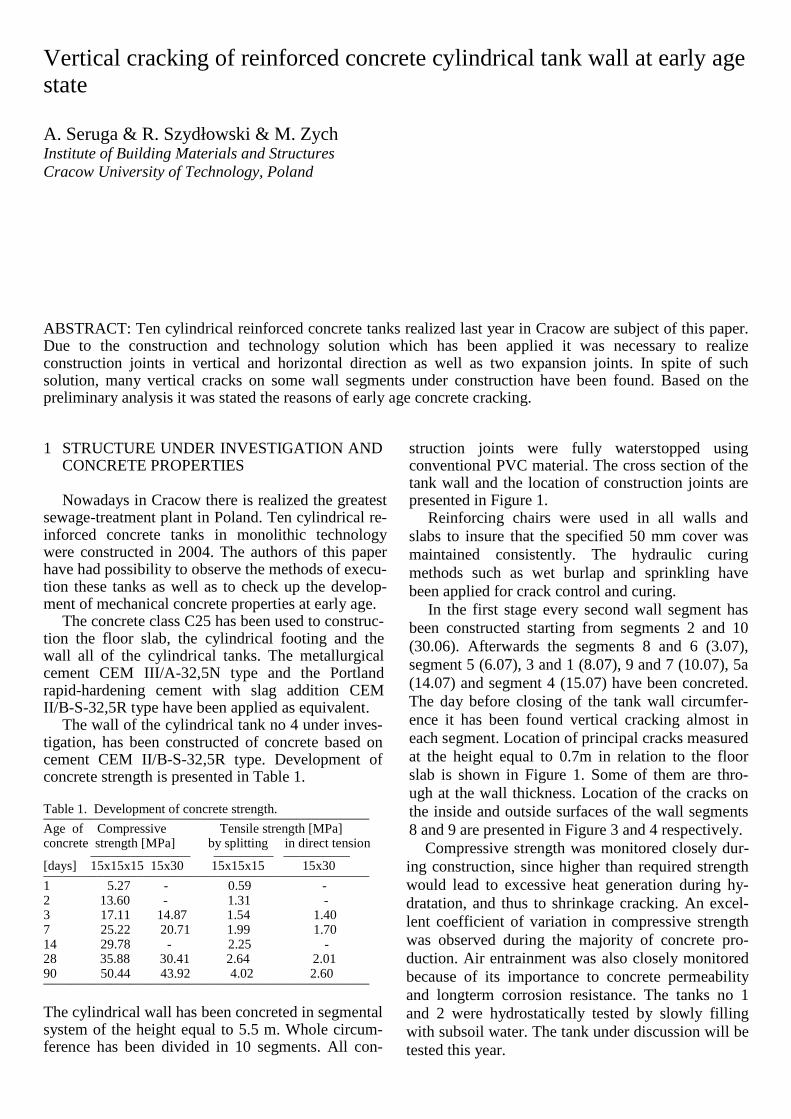
struction joints were fully waterstopped using conventional PVC material. The cross section of the tank wall and the location of construction joints are presented in Figure 1.
Reinforcing chairs were used in all walls and slabs to insure that the specified 50 mm cover was maintained consistently. The hydraulic curing methods such as wet burlap and sprinkling have been applied for crack control and curing.
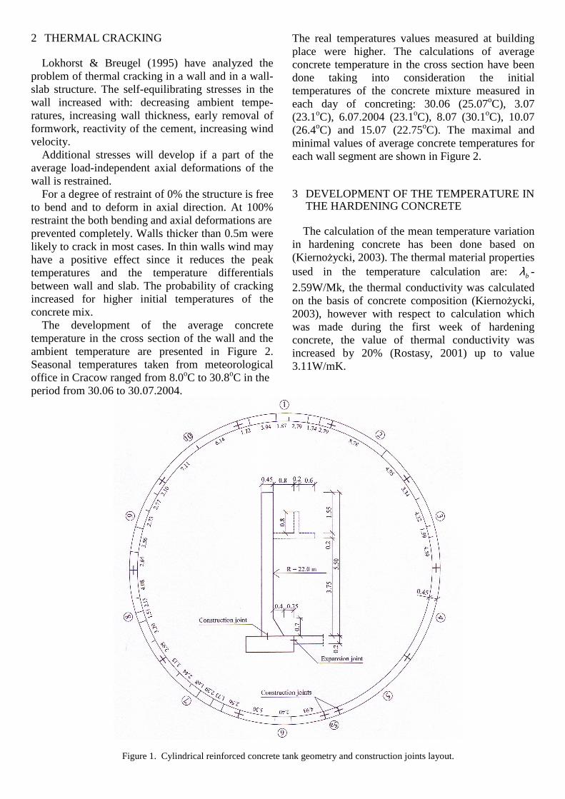
In the first stage every second wall segment has been constructed starting from segments 2 and 10 (30.06). Afterwards the segments 8 and 6 (3.07), segment 5 (6.07), 3 and 1 (8.07), 9 and 7 (10.07), 5a (14.07) and segment 4 (15.07) have been concreted. The day before closing of the tank wall circumfer-ence it has been found vertical cracking almost in each segment. Location of principal cracks measured at the height equal to 0.7m in relation to the floor slab is shown in Figure 1. Some of them are thro-ugh at the wall thickness. Location of the cracks on the inside and outside surfaces of the wall segments 8 and 9 are presented in Figure 3 and 4 respectively.
Compressive strength was monitored closely dur-ing construction, since higher than required strength would lead to excessive heat generation during hy-dratation, and thus to shrinkage cracking. An excel-lent coefficient of variation in compressive strength was observed during the majority of concrete pro-duction. Air entrainment was also closely monitored because of its importance to concrete permeability and longterm corrosion resistance. The tanks no 1 and 2 were hydrostatically tested by slowly filling with subsoil water. The tank under discussion will be tested this year.
Vertical cracking of reinforced concrete cylindrical tank wall at early age state
A. Seruga & R. Szydłowski & M. Zych Institute of Building Materials and Structures Cracow University of Technology, Poland
ABSTRACT: Ten cylindrical reinforced concrete tanks realized last year in Cracow are subject of this paper. Due to the construction and technology solution which has been applied it was necessary to realize construction joints in vertical and horizontal direction as well as two expansion joints. In spite of such solution, many vertical cracks on some wall segments under construction have been found. Based on the preliminary analysis it was stated the reasons of early age concrete cracking.
2 THERMAL CRACKING
Lokhorst & Breugel (1995) have analyzed the problem of thermal cracking in a wall and in a wall-slab structure. The self-equilibrating stresses in the wall increased with: decreasing ambient tempe-ratures, increasing wall thickness, early removal of formwork, reactivity of the cement, increasing wind velocity.
Additional stresses will develop if a part of the average load-independent axial deformations of the wall is restrained.
For a degree of restraint of 0% the structure is free to bend and to deform in axial direction. At 100% restraint the both bending and axial deformations are prevented completely. Walls thicker than 0.5m were likely to crack in most cases. In thin walls wind may have a positive effect since it reduces the peak temperatures and the temperature differentials between wall and slab. The probability of cracking increased for higher initial temperatures of the concrete mix.
The development of the average concrete temperature in the cross section of the wall and the ambient temperature are presented in Figure 2. Seasonal temperatures taken from meteorological office in Cracow ranged from 8.0oC to 30.8oC in the period from 30.06 to 30.07.2004.
The real temperatures values measured at building place were higher. The calculations of average concrete temperature in the cross section have been done taking into consideration the initial temperatures of the concrete mixture measured in each day of concreting: 30.06 (25.07oC), 3.07 (23.1oC), 6.07.2004 (23.1oC), 8.07 (30.1oC), 10.07 (26.4oC) and 15.07 (22.75oC). The maximal and minimal values of average concrete temperatures for each wall segment are shown in Figure 2.
3 DEVELOPMENT OF THE TEMPERATURE IN THE HARDENING CONCRETE
The calculation of the mean temperature variation
in hardening concrete has been done based on (Kiernożycki, 2003). The thermal material properties used in the temperature calculation are: bλ -
2.59W/Mk, the thermal conductivity was calculated on the basis of concrete composition (Kiernożycki, 2003), however with respect to calculation which was made during the first week of hardening concrete, the value of thermal conductivity was increased by 20% (Rostasy, 2001) up to value 3.11W/mK.
Figure 1. Cylindrical reinforced concrete tank geometry and construction joints layout.

cb – 0.772kJ/kgK, the coefficient of heat capacity also was calculated based on the concrete composi-tion .
α - 5.8W/m2K, the convection coefficient was as-sumed according to Townsend (1959) under the as-sumption that the value of wind speed is equal to zero. In case of the wall in the formwork it has been assumed the substitute convection coefficient wα ex-pressed as follows:
1+=
ααα
Rw and λd
R =
where: d = the thickness of the formwork, λ = the thermal conductivity of the formwork.
The solution of the heat transport equation (2) in case of one-way heat transport with the assumption that a function Q is described by (3), is given by K. Hirschfeld (1948). Based on the assumption that the heat transfer on the both surfaces of concrete wall is the same, the mean temperature in a cross section of the wall can be written as follows:
( ) ( ) ...exp2
12)( +−⋅
−+−
= tKc
qC
Kdck
KdcktT Tp
bbTpbb
Tpbb
γγαγα
...2
⋅
−−−
bbTpno
Tpop cdK
qCdKTT
γα
( ) obb
o Ttdc
f +
−
γαϕ exp1 (1)
bbb c
QTa
T
γττ ⋅⋅
∂∂+∇⋅=
∂∂ 12 (2)
( ) ( )[ ]tKqCQ Tp ⋅−−⋅⋅= exp1τ (3)
where: 1ϕ = is the solution of: iBd
tg ==λ
αϕϕ211 ,
b
Tp
a
KdP
4
2
= - Predwoditielew`s number,
( )
+
=
1
121
12
1
2
2sin1
sin2
ϕϕϕ
ϕϕf , d
no
212λϕα = .
PPctgk ⋅= , To – temperature of atmospheric air, Tp – initial temperature of concrete.
The influence of the ambient temperature on the mean temperature in the wall has been taken into account by calculating changes in time of relative difference temperatures value (mean on the whole cross section) depending on Fourier`s number (Bogosłowski 1975).
The solution of the temperature development in hardening concrete presented above, is only an ap-proximation of the real temperature in the cross
section, because it has not been taken into account the effect of the solar radiation and the distribution of the temperature in the cross section. Moreover, in the calculation it has not been taken into account the influence of the moisture on the temperature. In the further works these phenomena will be taken into the analysis.
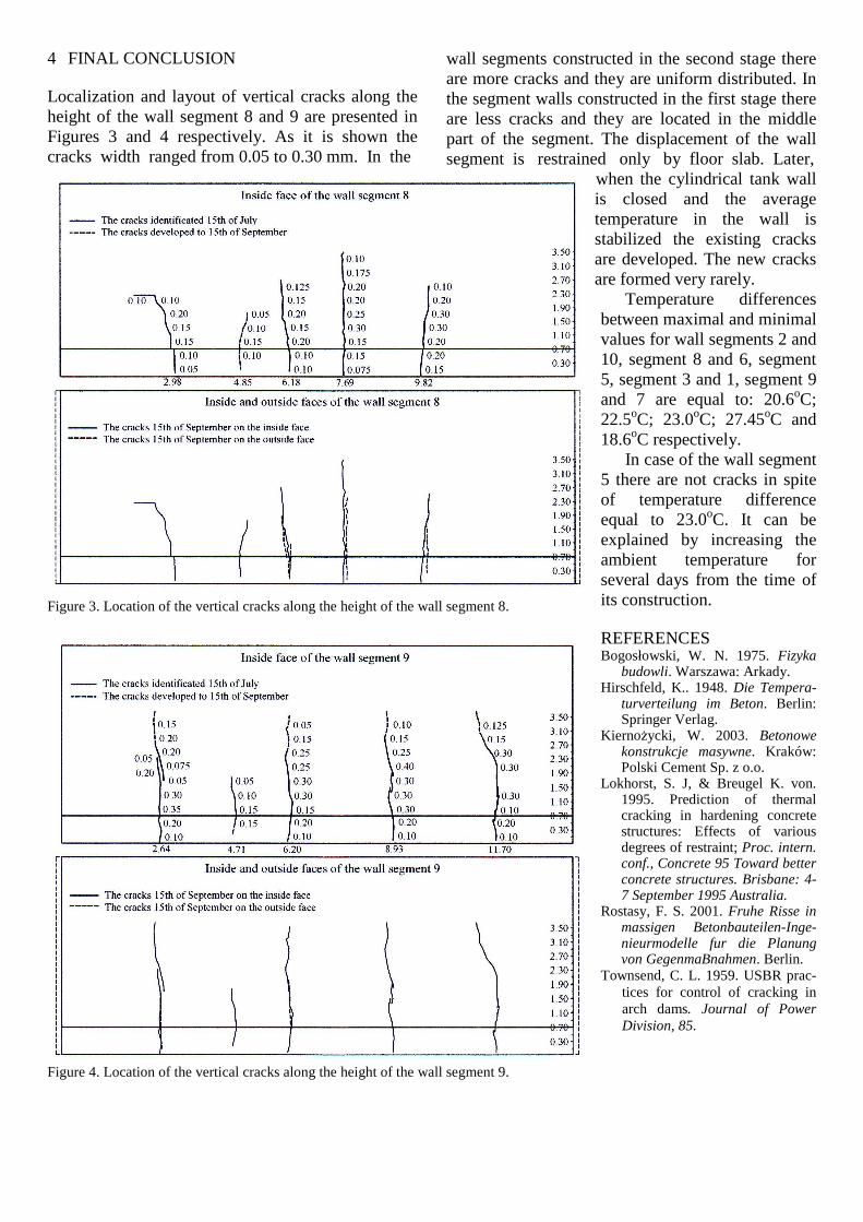
4 FINAL CONCLUSION Localization and layout of vertical cracks along the height of the wall segment 8 and 9 are presented in Figures 3 and 4 respectively. As it is shown the cracks width ranged from 0.05 to 0.30 mm. In the
wall segments constructed in the second stage there are more cracks and they are uniform distributed. In the segment walls constructed in the first stage there are less cracks and they are located in the middle part of the segment. The displacement of the wall segment is restrained only by floor slab. Later,
Figure 3. Location of the vertical cracks along the height of the wall segment 8.
Figure 4. Location of the vertical cracks along the height of the wall segment 9.
when the cylindrical tank wall is closed and the average temperature in the wall is stabilized the existing cracks are developed. The new cracks are formed very rarely.
Temperature differences between maximal and minimal values for wall segments 2 and 10, segment 8 and 6, segment 5, segment 3 and 1, segment 9 and 7 are equal to: 20.6oC; 22.5oC; 23.0oC; 27.45oC and 18.6oC respectively.
In case of the wall segment 5 there are not cracks in spite of temperature difference equal to 23.0oC. It can be explained by increasing the ambient temperature for several days from the time of its construction.
REFERENCES Bogosłowski, W. N. 1975. Fizyka
budowli. Warszawa: Arkady. Hirschfeld, K.. 1948. Die Tempera-
turverteilung im Beton. Berlin: Springer Verlag.
Kiernożycki, W. 2003. Betonowe konstrukcje masywne. Kraków: Polski Cement Sp. z o.o.
Lokhorst, S. J, & Breugel K. von. 1995. Prediction of thermal cracking in hardening concrete structures: Effects of various degrees of restraint; Proc. intern. conf., Concrete 95 Toward better concrete structures. Brisbane: 4-7 September 1995 Australia.
Rostasy, F. S. 2001. Fruhe Risse in massigen Betonbauteilen-Inge-nieurmodelle fur die Planung von GegenmaBnahmen. Berlin.
Townsend, C. L. 1959. USBR prac-tices for control of cracking in arch dams. Journal of Power Division, 85.