Embed Size (px)
Citation preview

Welcome
To The
Presentation
1

PresentationOn
Cracking in Reinforced Concrete Flexural Members
InstructorProf. Dr. Engr. Md. Monirul Islam
Chair & course coordinatorof
Civil engineering department2

Group Number
3
Group MembersSl. Name ID#
1.
2.
3.
4.
5.
6.
7.
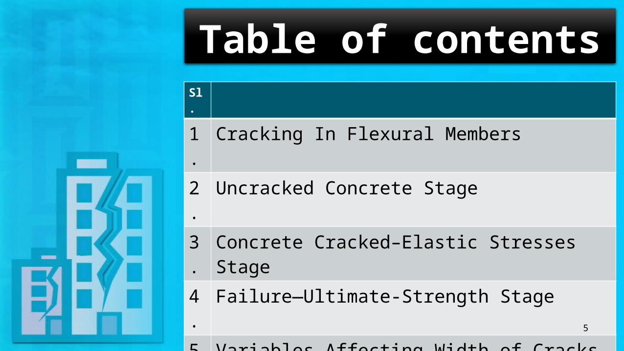
Table of contentsSl.
1. Cracking In Flexural Members2. Uncracked Concrete Stage3. Concrete Cracked–Elastic Stresses Stage4. Failure—Ultimate-Strength Stage 5. Variables Affecting Width of Cracks6. Equations for Crack Width7. ACI Code Provisions for Crack Control8. Example
5

Cracking In Flexural MembersAll reinforced concrete beams crack, generally starting at loads well below service level, and possibly even prior to loading due to restrained shrinkage. Flexural cracking due to loads is not only inevitable, but actually necessary for the reinforcement to be used effectively. Prior to the formation of flexural cracks, the steel stress is no more than n times the stress in the adjacent concrete, where n is the modular ratio E5/Ec. For materials common in current practice, n is approximately 8.

Cracking In Flexural Members Cont’dIn a well-designed beam, flexural cracks are fine, so-called hairline cracks, almost invisible to the casual observer, and they permit little if any corrosion of the reinforcement. As loads are gradually increased above the cracking load, both the number and the width of cracks increase, and at service load level a maximum width of crack of about 0.016 in. is typical. If loads are further increased, crack widths increase further.
Fig: hairline cracks
Uncracked Concrete StageAt small loads when the tensile stresses are less than the modulus of rupture (the bending tensile stress at which the concrete begins to crack), the entire cross section of the beam resists bending, with compression on one side and tension on the other. Figure shows the variation of stresses and strains for these small loads.
:

Concrete Cracked–Elastic Stresses StageAs the load is increased after the modulus of rupture of the concrete is exceeded, cracks begin to develop in the bottom of the beam. The moment at which these cracks begin to form—that is, when the tensile stress in the bottom of the beam equals the modulus of rupture—is referred to as the cracking moment, Mcr. As the load is further increased, these cracks quickly spread up to the vicinity of the neutral axis, and then the neutral axis begins to move upward. The cracks occur at those places along the beam where the actual moment is greater than the cracking moment, as shown in Figure next slide.

Concrete Cracked–Elastic Stresses Stage Cont’d

Failure—Ultimate-Strength Stage

Failure—Ultimate-Strength Stage Cont’d

Variables Affecting Width of CracksCrack width is proportional to fn
s, where fs is the steel stress and n is an exponent that varies in the range from about 1.0 to 1.4. For steel stresses in the range of practical interest, say from 20 to 36 ksi, n may be taken equal to 1.0. The steel stress is easily computed based on elastic cracked-section analysis. Alternatively, fs,may be taken equal to ~J. Generally, to control cracking, it is better to use a larger number of smaller-diameter bars to provide the required As than to use the minimum number of larger bars, and the bars should be well distributed over the tensile zone of the concrete. For deep flexural members, this includes additional reinforcement on the sides of the web to prevent excessive surface crack widths above or below the level of the main flexural reinforcement.

Variables Affecting Width of Cracks Cont’d

Equations for Crack WidthFor the maximum crack width at the tension face of a beam. They are, respectively,

Equations for Crack Width Cont’d

ACI Code Provisions for Crack Control

ACI Code Provisions for Crack Control Cont’d

ACI Code Provisions for Crack Control Cont’d
For beams with relatively deep webs, some reinforcement should be placed near the vertical faces of the web to control the width of cracks in the concrete tension zone above the level of the main reinforcement. Without such steel, crack widths in the web wider than those at the level of the main bars have been observed. According to ACI Code 10.6.7, if the total depth of the beam h exceeds 36 in., longitudinal "skin“ reinforcement must be uniformly distributed along both side faces of the member for a distance h/2 nearest the flexural tension steel.

ACI Code Provisions for Crack Control Cont’d

Example

Example Cont’d Here, fs = Steel Stress
Ms = Service load moment
As = Steel Area
hf = Flange Thickness d = Depth
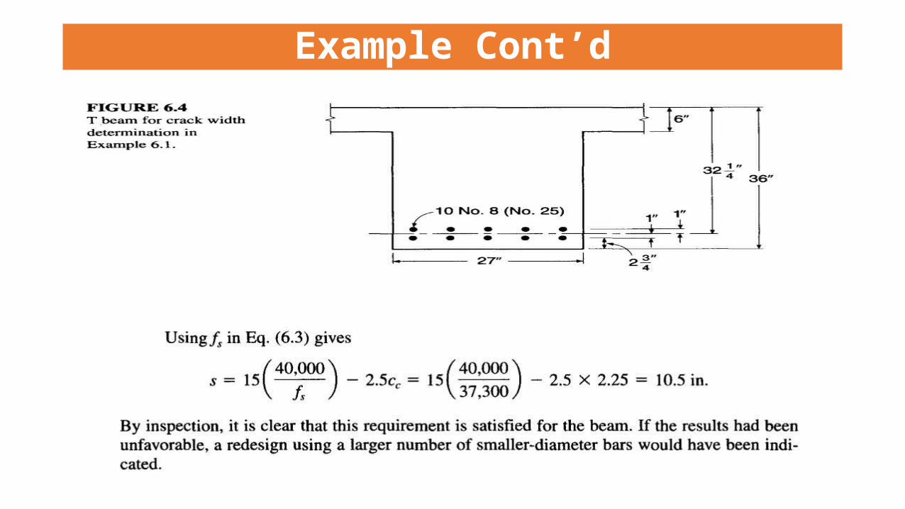
Example Cont’d

24

Any Enquiry?
25