Embed Size (px)
Citation preview

Pro ToolsDigiRack Plug-Ins Guide
Version 6.1 for TDM or LE Systems on Windows or MacintoshVersion 5.1.1 to 5.3x for TDM or LE Systems on Macintosh
Digidesign
2001 Junipero Serra Boulevard
Daly City, CA 94014-3886 USA
tel: 650·731·6300
fax: 650·731·6399
Technical Support (USA)
tel: 650·731·6100
fax: 650·731·6384
Product Information (USA)
tel: 650·731·6102
tel: 800·333·2137
International Offices
Visit the Digidesign Web site
for contact information
Web Site
www.digidesign.com

Copyright
This guide is copyrighted ©2003 by Digidesign, a division of Avid Technology, Inc. (hereafter “Digidesign”), with all rights reserved. Under copyright laws, this guide may not be duplicated in whole or in part without the written consent of Digidesign.
DIGIDESIGN, AVID and PRO TOOLS are trademarks or registered trademarks of Digidesign and/or Avid Technology, Inc. All other trademarks are the property of their respective owners.
All features and specifications subject to change without notice.
PN 910611590-00 REV A 6/03

contents
Chapter 1. Introduction . . . . . . . . . . . . . . . . . . . . . . . . . . . . . . . . . . . . . . . . . . . . . . . . . . . . . . 1
Plug-In Formats. . . . . . . . . . . . . . . . . . . . . . . . . . . . . . . . . . . . . . . . . . . . . . . . . . . . . . . . . . 1
System Requirements . . . . . . . . . . . . . . . . . . . . . . . . . . . . . . . . . . . . . . . . . . . . . . . . . . . . . 2
Conventions Used in This Guide . . . . . . . . . . . . . . . . . . . . . . . . . . . . . . . . . . . . . . . . . . . . . . 2
Chapter 2. Installation . . . . . . . . . . . . . . . . . . . . . . . . . . . . . . . . . . . . . . . . . . . . . . . . . . . . . . . 3
Installing Plug-Ins . . . . . . . . . . . . . . . . . . . . . . . . . . . . . . . . . . . . . . . . . . . . . . . . . . . . . . . . 3
Allocating Additional Memory to Pro Tools . . . . . . . . . . . . . . . . . . . . . . . . . . . . . . . . . . . . . . . 3
Chapter 3. Working with Real-Time Plug-Ins . . . . . . . . . . . . . . . . . . . . . . . . . . . . . . . . . . . . 5
Processing Power Requirements of TDM and RTAS Plug-Ins . . . . . . . . . . . . . . . . . . . . . . . . . . 5
Delay in Digital Signal Processing . . . . . . . . . . . . . . . . . . . . . . . . . . . . . . . . . . . . . . . . . . . . . 7
Plug-Ins as Inserts . . . . . . . . . . . . . . . . . . . . . . . . . . . . . . . . . . . . . . . . . . . . . . . . . . . . . . . . 8
Inserting Plug-Ins on Tracks . . . . . . . . . . . . . . . . . . . . . . . . . . . . . . . . . . . . . . . . . . . . . . . . . 9
The Plug-In Window. . . . . . . . . . . . . . . . . . . . . . . . . . . . . . . . . . . . . . . . . . . . . . . . . . . . . . 11
Editing Plug-In Controls . . . . . . . . . . . . . . . . . . . . . . . . . . . . . . . . . . . . . . . . . . . . . . . . . . . 14
Using a Key Input for Side-Chain Processing . . . . . . . . . . . . . . . . . . . . . . . . . . . . . . . . . . . . 15
Automating Plug-Ins . . . . . . . . . . . . . . . . . . . . . . . . . . . . . . . . . . . . . . . . . . . . . . . . . . . . . 16
Using the Librarian . . . . . . . . . . . . . . . . . . . . . . . . . . . . . . . . . . . . . . . . . . . . . . . . . . . . . . 17
Chapter 4. Working with AudioSuite Plug-Ins . . . . . . . . . . . . . . . . . . . . . . . . . . . . . . . . . . 21
The AudioSuite Window . . . . . . . . . . . . . . . . . . . . . . . . . . . . . . . . . . . . . . . . . . . . . . . . . . . 22
The AudioSuite Processing Preferences Dialog . . . . . . . . . . . . . . . . . . . . . . . . . . . . . . . . . . . 27
Using AudioSuite Plug-Ins. . . . . . . . . . . . . . . . . . . . . . . . . . . . . . . . . . . . . . . . . . . . . . . . . . 28
Contents iii

iv
Chapter 5. DigiRack Real-Time TDM and RTAS Plug-Ins. . . . . . . . . . . . . . . . . . . . . . . . 31
EQ II . . . . . . . . . . . . . . . . . . . . . . . . . . . . . . . . . . . . . . . . . . . . . . . . . . . . . . . . . . . . . . . . 31
Click . . . . . . . . . . . . . . . . . . . . . . . . . . . . . . . . . . . . . . . . . . . . . . . . . . . . . . . . . . . . . . . . 33
Dither . . . . . . . . . . . . . . . . . . . . . . . . . . . . . . . . . . . . . . . . . . . . . . . . . . . . . . . . . . . . . . . 34
POW-r Dither . . . . . . . . . . . . . . . . . . . . . . . . . . . . . . . . . . . . . . . . . . . . . . . . . . . . . . . . . . 35
D-Verb . . . . . . . . . . . . . . . . . . . . . . . . . . . . . . . . . . . . . . . . . . . . . . . . . . . . . . . . . . . . . . . 37
Dynamics II . . . . . . . . . . . . . . . . . . . . . . . . . . . . . . . . . . . . . . . . . . . . . . . . . . . . . . . . . . . 39
Mod Delay and Mod Delay II . . . . . . . . . . . . . . . . . . . . . . . . . . . . . . . . . . . . . . . . . . . . . . . 46
Signal Generator . . . . . . . . . . . . . . . . . . . . . . . . . . . . . . . . . . . . . . . . . . . . . . . . . . . . . . . 50
Pitch . . . . . . . . . . . . . . . . . . . . . . . . . . . . . . . . . . . . . . . . . . . . . . . . . . . . . . . . . . . . . . . . 50
TimeAdjuster . . . . . . . . . . . . . . . . . . . . . . . . . . . . . . . . . . . . . . . . . . . . . . . . . . . . . . . . . . 53
Trim . . . . . . . . . . . . . . . . . . . . . . . . . . . . . . . . . . . . . . . . . . . . . . . . . . . . . . . . . . . . . . . . 56
Chapter 6. DigiRack AudioSuite Plug-Ins . . . . . . . . . . . . . . . . . . . . . . . . . . . . . . . . . . . . . 57
EQ II . . . . . . . . . . . . . . . . . . . . . . . . . . . . . . . . . . . . . . . . . . . . . . . . . . . . . . . . . . . . . . . . 57
Dynamics II . . . . . . . . . . . . . . . . . . . . . . . . . . . . . . . . . . . . . . . . . . . . . . . . . . . . . . . . . . . 58
Chorus . . . . . . . . . . . . . . . . . . . . . . . . . . . . . . . . . . . . . . . . . . . . . . . . . . . . . . . . . . . . . . 59
Flanger . . . . . . . . . . . . . . . . . . . . . . . . . . . . . . . . . . . . . . . . . . . . . . . . . . . . . . . . . . . . . . 60
Multi-Tap Delay . . . . . . . . . . . . . . . . . . . . . . . . . . . . . . . . . . . . . . . . . . . . . . . . . . . . . . . . 61
Ping-Pong Delay . . . . . . . . . . . . . . . . . . . . . . . . . . . . . . . . . . . . . . . . . . . . . . . . . . . . . . . . 62
Invert . . . . . . . . . . . . . . . . . . . . . . . . . . . . . . . . . . . . . . . . . . . . . . . . . . . . . . . . . . . . . . . 63
Duplicate. . . . . . . . . . . . . . . . . . . . . . . . . . . . . . . . . . . . . . . . . . . . . . . . . . . . . . . . . . . . . 64
Delay . . . . . . . . . . . . . . . . . . . . . . . . . . . . . . . . . . . . . . . . . . . . . . . . . . . . . . . . . . . . . . . 64
Normalize . . . . . . . . . . . . . . . . . . . . . . . . . . . . . . . . . . . . . . . . . . . . . . . . . . . . . . . . . . . . 65
Gain . . . . . . . . . . . . . . . . . . . . . . . . . . . . . . . . . . . . . . . . . . . . . . . . . . . . . . . . . . . . . . . . 65
Reverse . . . . . . . . . . . . . . . . . . . . . . . . . . . . . . . . . . . . . . . . . . . . . . . . . . . . . . . . . . . . . . 66
Signal Generator . . . . . . . . . . . . . . . . . . . . . . . . . . . . . . . . . . . . . . . . . . . . . . . . . . . . . . . 66
DC Offset Removal . . . . . . . . . . . . . . . . . . . . . . . . . . . . . . . . . . . . . . . . . . . . . . . . . . . . . . 67
Time Compression/ Expansion. . . . . . . . . . . . . . . . . . . . . . . . . . . . . . . . . . . . . . . . . . . . . . 67
Pitch Shift . . . . . . . . . . . . . . . . . . . . . . . . . . . . . . . . . . . . . . . . . . . . . . . . . . . . . . . . . . . . 69
DigiRack Plug-Ins Guide

Chapter 7. Using Digi ReWire (Pro Tools 6.1 Only) . . . . . . . . . . . . . . . . . . . . . . . . . . . . . 71
ReWire Requirements . . . . . . . . . . . . . . . . . . . . . . . . . . . . . . . . . . . . . . . . . . . . . . . . . . . . 72
Using ReWire . . . . . . . . . . . . . . . . . . . . . . . . . . . . . . . . . . . . . . . . . . . . . . . . . . . . . . . . . . 72
Tempo and Meter Changes . . . . . . . . . . . . . . . . . . . . . . . . . . . . . . . . . . . . . . . . . . . . . . . . 73
Looping Playback . . . . . . . . . . . . . . . . . . . . . . . . . . . . . . . . . . . . . . . . . . . . . . . . . . . . . . . 74
Automating ReWire . . . . . . . . . . . . . . . . . . . . . . . . . . . . . . . . . . . . . . . . . . . . . . . . . . . . . . 74
Chapter 8. Using DirectConnect (Mac OS 9 Only). . . . . . . . . . . . . . . . . . . . . . . . . . . . . . 75
DirectConnect Requirements . . . . . . . . . . . . . . . . . . . . . . . . . . . . . . . . . . . . . . . . . . . . . . . 75
DirectConnect and Other DAE Applications . . . . . . . . . . . . . . . . . . . . . . . . . . . . . . . . . . . . . 77
Installing DirectConnect . . . . . . . . . . . . . . . . . . . . . . . . . . . . . . . . . . . . . . . . . . . . . . . . . . . 77
Using DirectConnect . . . . . . . . . . . . . . . . . . . . . . . . . . . . . . . . . . . . . . . . . . . . . . . . . . . . . 77
Automating DirectConnect . . . . . . . . . . . . . . . . . . . . . . . . . . . . . . . . . . . . . . . . . . . . . . . . . 79
Recalling DirectConnect States. . . . . . . . . . . . . . . . . . . . . . . . . . . . . . . . . . . . . . . . . . . . . . 80
Appendix A. DSP Requirements for TDM Plug-Ins . . . . . . . . . . . . . . . . . . . . . . . . . . . . . . 81
Appendix B. DSP Delays Incurred by TDM Plug-Ins . . . . . . . . . . . . . . . . . . . . . . . . . . . . . 89
Index . . . . . . . . . . . . . . . . . . . . . . . . . . . . . . . . . . . . . . . . . . . . . . . . . . . . . . . . . . . . . . . . . . . . . 91
Contents v

vi
DigiRack Plug-Ins Guide
chapter 1
Introduction
Plug-ins are special-purpose software compo-nents that provide additional signal processing functionality to Pro Tools.
The DigiRack plug-ins included with Pro Tools provide a comprehensive set of digital signal processing effects that include EQ, dynamics, delay, and other essential functions.
Plug-In FormatsThere are three formats of plug-ins:
• TDM plug-ins (real-time, DSP-based)
• RTAS plug-ins (real-time, host-based)
• AudioSuite plug-ins (non-real-time, file-based processing)
TDM Plug-Ins(TDM Systems Only)
TDM plug-ins function as track inserts, are ap-plied to audio during playback, and process au-dio non-destructively in real time. TDM plug-ins are designed for use on TDM-based Pro Tools systems, and rely on the processing power of Digidesign DSP cards.
The number and variety of TDM plug-ins that you can use simultaneously in a session are lim-ited only by the amount of DSP available. You can increase available DSP by installing addi-
tional DSP cards in your computer. On HD-se-ries systems, use HD Core or HD Process cards; on MIX-series systems, use MIX Core, MIX Farm, or DSP Farm cards. This power-on-demand aspect is a significant advantage of TDM-based systems.
RTAS Plug-Ins
RTAS (Real-Time AudioSuite) plug-ins provide features and functionality similar to their TDM counterparts, but unlike TDM plug-ins, they rely on and are limited by the processing power of your computer. The more powerful your com-puter, the greater the number and variety of RTAS plug-ins that you can use simultaneously.
Because of this dependence on the CPU or host processing, the more RTAS plug-ins you use con-currently in a session, the greater the impact it will have on other aspects of your system’s per-formance, such as maximum track count, the density of edits possible, and latency in automa-tion and recording.
RTAS plug-ins can be used on both Pro Tools TDM and LE systems.
MIX Farm and DSP Farm cards are not supported on HD-series systems.
Chapter 1: Introduction 1

2
AudioSuite Plug-Ins
Non-real-time AudioSuite plug-ins are not used during playback, but are instead used to process audio files on disk, creating new, rewritten audio files with the effect permanently applied. Audio-Suite plug-ins can be used on all Pro Tools sys-tems.
System RequirementsTo use DigiRack plug-ins you need:
◆ A Digidesign-approved Pro Tools system
– or –
◆ A third-party software application that sup-ports the Digidesign TDM or AudioSuite plug-in standard
Digidesign can only assure compatibility and provide support for hardware and software it has tested and approved. For a list of Digidesign-qualified computers, operating systems, hard drives, and third-party devices, refer to the latest compatibility information on the Digidesign Web site (www.digidesign.com/compato).
DigiRack Plug-Ins Guide
Conventions Used in This GuideAll Digidesign guides use the following conven-tions to indicate menu choices and key com-mands::
The following symbols are used to highlight im-portant information:
Convention Action
File > Save Session Choose Save Session from the File menu
Control+N Hold down the Control key and press the N key
Control-click Hold down the Control key and click the mouse button
Right-click (Windows) Click with the right mouse button
User Tips are helpful hints for getting the most from your Pro Tools system.
Important Notices include information that could affect your Pro Tools session data or the performance of your Pro Tools system.
Shortcuts show you useful keyboard or mouse shortcuts.
Cross References point to related sections in the Pro Tools Guides.

chapter 2
Installation
Installing Plug-InsThe Digidesign DigiRack Plug-Ins are installed when you install Pro Tools. For more informa-tion about installing Pro Tools, see the Getting Started Guide that came with your system.
Allocating Additional Memory to Pro Tools(Mac OS 9 Only)
If you plan to use a large number of TDM plug-ins in addition to the DigiRack TDM plug-ins in-cluded with Pro Tools, allocating additional memory to Pro Tools will help ensure reliable system performance.
If enough RAM is available in your computer, al-locate 1–2 megabytes of additional RAM to Pro Tools for each non-DigiRack plug-in in-stalled on your system.
DigiRack plug-ins versions 5.3.x and earlier are not supported in Pro Tools 6.x.
To allocate additional memory to Pro Tools:
1 Start Pro Tools so that it can calculate its basic memory allocation.
2 Go to the Finder and choose About This Com-puter from the Apple menu.
3 If you have 3 MB or more of memory available (as indicated in the Largest Unused Block por-tion of this window), go to step 4. If you have less than 3 MB of free memory, stop here: Do not allocate additional memory to Pro Tools un-less you install additional RAM in your com-puter.
4 Quit Pro Tools.
5 Open the Pro Tools folder, select the Pro Tools application, and choose Get Info from the Finder’s File menu.
6 Choose Memory from the Show menu.
7 Enter the desired amount of memory above the minimum requirement in the Preferred Size field. For example, if the Preferred Size field currently says “30410”k and you want to allocate an addi-tional 3 MB of memory (1 megabyte equals 1,024 kilobytes), enter “33482”k into the Pre-ferred Size field.
8 Close the Get Info dialog.
The next time you start Pro Tools, it will use this new memory allocation.
Chapter 2: Installation 3

4
DigiRack Plug-Ins Guide
chapter 3
Working with Real-Time Plug-Ins
Real-time plug-ins process audio nondestruc-tively in real time. They do not alter the original source audio, but only apply their effect during playback.
There are two formats of real-time plug-ins:
TDM Plug-Ins Rely on the processing power of Digidesign DSP cards. TDM plug-ins run only on Pro Tools TDM systems.
RTAS Plug-Ins Rely on the processing power of your computer. RTAS plug-ins run on Pro Tools TDM and LE systems.
Processing Power Requirements of TDM and RTAS Plug-InsTDM and RTAS plug-ins differ in their process-ing power requirements.
TDM Plug-Ins
Each real-time TDM plug-in in a Pro Tools ses-sion uses a portion of your system’s total avail-able DSP resources. Since these DSP resources re-side on the cards that make up your particular Pro Tools hardware configuration, the amount of DSP available depends entirely on the num-ber and type of DSP cards in your system.
You can add more mixing and processing power to your system by installing additional DSP cards, provided you have unused PCI expansion slots in your computer or use a Digidesign-ap-proved Expansion Chassis.
The System Usage window (Windows > Show System Usage) shows how much DSP is available on your system and how it is currently being used.
For more information on the System Usage window, see the Pro Tools Reference Guide.
System Usage window
Chapter 3: Working with Real-Time Plug-Ins 5

6
DSP Sharing Between TDM Plug-Ins
With Digidesign’s MultiShell II technology, dif-ferent types of TDM plug-ins can share the same DSP chip at the same time. This lets you simul-taneously use a greater variety of plug-ins by ef-ficiently managing the DSP available on each chip in your system.
To take advantage of this capability, plug-ins must be MultiShell II compatible. All DigiRack TDM plug-ins with the exception of Direct Connect and Pitch are MultiShell II com-patible.
Some third-party plug-ins may not be Multi-Shell II compatible. To check compatibility, contact the developer.
RTAS Plug-Ins
RTAS plug-ins rely on and are limited by the pro-cessing power of your computer’s CPU. The more RTAS plug-ins you use concurrently in a session, the greater the impact it will have on other aspects of your system’s performance, such as maximum track count, the density of edits possible, and latency in automation and recording.
The CPU meter in the System Usage window (Windows > Show System Usage) shows how much of your computer’s processing power is currently being used by Pro Tools, and how much is still available.
See Appendix A, “DSP Requirements for TDM Plug-Ins” for the number of instances of each DigiRack TDM plug-in that can be powered by a single DSP chip. DSP usage differs according to card type.
For more information on the System Usage window, see the Pro Tools Reference Guide.
DigiRack Plug-Ins Guide
Improving RTAS Plug-In Performance
You can increase the number of RTAS plug-ins your system can use concurrently by increasing the Hardware Buffer Size and CPU Usage Limit.
Hardware Buffer Size
The Hardware Buffer Size (H/W Buffer Size) con-trols the size of the hardware cache used to han-dle host processing tasks such as Real-Time Au-dioSuite (RTAS) plug-ins.
◆ Lower Hardware Buffer Size settings reduce monitoring latency, and are useful when you are recording live input.
◆ Higher Hardware Buffer Size settings allow more audio processing and effects, and are use-ful when mixing and using more RTAS plug-ins.
To change the Hardware Buffer Size:
1 Choose Setups > Playback Engine.
2 From the H/W Buffer Size pop-up menu, select the audio buffer size, in samples.
3 Click OK.
In addition to causing slower screen re-sponse and monitoring latency, higher Hardware Buffer Size settings can affect the accuracy of plug-in automation, mute data, and timing for MIDI tracks.

CPU Usage Limit
The CPU Usage Limit controls the percentage of CPU resources allocated to Pro Tools host pro-cessing tasks.
◆ Lower CPU Usage Limit settings limit the ef-fect of Pro Tools processing on other CPU-inten-sive tasks, such as screen redraws, and are useful when you are experiencing slow system re-sponse, or when running other applications at the same time as Pro Tools.
◆ Higher CPU Usage Limit settings allocate more processing power to Pro Tools, and are useful for playing back large sessions or using more real-time plug-ins.
To change the CPU Usage Limit:
1 Choose Setups > Playback Engine.
2 From the CPU Usage Limit pop-up menu, se-lect the percentage of CPU processing you want to allocate to Pro Tools.
3 Click OK.
Increasing the CPU Usage Limit may slow down screen response on slower computers.
Playback Engine dialog
For more information on the Hardware Buffer Size and CPU Usage Limit, refer to the Pro Tools Reference Guide.
Delay in Digital Signal ProcessingDSP processing in digital audio systems incurs signal delay of varying amounts. Such delays can vary from as short as few samples to as long as several hundred samples, depending on the type of processing applied.
If you have recorded an instrument on multiple tracks using multiple microphones (a drum kit for example) and process the different tracks with different plug-ins, the tracks may go out of phase. You will then need to compensate for these delays to avoid phase cancellation prob-lems.
Compensating for Delay with TimeAdjuster(TDM Systems Only)
You can compensate for TDM plug-in-induced delays by using the TimeAdjuster plug-in. With this plug-in you can apply a specific number of samples of delay to the signal path of a Pro Tools track. TimeAdjuster provides settings files that apply the correct compensation time in samples for delay introduced by one or more plug-ins. See “TimeAdjuster” on page 53.
See Appendix B, “DSP Delays Incurred by TDM Plug-Ins” for information on delays inherent in specific DigiRack TDM plug-ins. See the Pro Tools Reference Guide for a guide to calculating DSP-induced delays.
Chapter 3: Working with Real-Time Plug-Ins 7

8
Plug-Ins as InsertsReal-time plug-ins are available as in-line inserts on audio tracks, Auxiliary Inputs, and Master Faders. A maximum of 5 real-time plug-ins can be used per track.
When more than one insert is used on a track, they process the audio in series, each effect be-ing added to the previous one, from top to bot-tom in the Mix window.
Inserts can be used in two ways:
On Single Tracks An insert can be applied to an individual audio track or Auxiliary Input using the Insert Selector on that track.
With in-line inserts, you control the level of ef-fect by adjusting the controls of the plug-in.
As Shared Resources An insert can be used as a shared resource in a send-and-return arrange-ment by bussing signals from several tracks to an Auxiliary Input, and applying the insert to the Auxiliary Input track. With such an arrange-ment, you can control the send level for each track and the overall level of the effect can be controlled from the Auxiliary Input track.
Shared arrangements let you make more effi-cient use of your system’s processing power.
If you are using both TDM and RTAS plug-ins on the same track, RTAS plug-ins must occur first in the signal chain, followed by TDM plug-ins. You cannot place TDM plug-ins before RTAS plug-ins.
On TDM systems, RTAS plug-ins can be in-serted on audio tracks only. For Auxiliary Inputs or Master Faders, use TDM plug-ins.
DigiRack Plug-Ins Guide
Pre-Fader Operation
Real-time plug-ins function as pre-fader inserts (except on Master Fader tracks, where inserts are post-fader), meaning that their input levels are not affected by a track’s volume fader.
Real-time plug-ins are pre-fader, but post-disk. This means that if you record to disk with a plug-in inserted on the record track, you will hear the effect of the plug-in, but the effect will not be recorded to disk.
To record with a plug-in effect, create an Auxil-iary Input, insert the desired effect on the Aux-iliary Input track, then route the Auxiliary Input to the audio track to which you want to record. Alternatively, bounce the audio track with the plug-in after recording in order to write the ef-fected audio to disk.
Mono, Multi-Mono, and Multichannel Plug-Ins
Plug-ins can be used in mono, multi-mono, or multichannel formats, depending on the type of plug-in and whether the destination is a mono or multichannel track.
In general, when working with stereo and greater-than-stereo tracks, use multichannel plug-ins. If a multichannel version of a plug-in is not available, use a multi-mono version.
Plug-in formats

Mono Plug-Ins Used on mono tracks. Some mono plug-ins (such as Mod Delay) can gener-ate stereo or greater-than-stereo output from a mono channel. Plug-ins that occur on a track af-ter a stereo plug-in are used in stereo as well.
Multi-Mono Plug-Ins Used on stereo or greater-than-stereo multichannel tracks when a multi-channel version of the plug-in is not available. Multi-mono plug-ins will analyze and process each channel independently without regard to each other. Controls for all channels are linked by default so that you can adjust them in tan-dem. You can unlink controls for independent adjustment using the Master Link button. See “Linking and Unlinking Controls on Multi-Mono Plug-ins” on page 14.
Multichannel Plug-Ins Used on stereo and greater-than-stereo multichannel tracks. On greater-than-stereo multichannel tracks, the controls for all channels are always linked to-gether.
Multi-mono plug-ins, such as dynamics-based or reverb plug-ins, may not function as you expect. Use the multichannel version of a multi-mono plug-in when available.
Inserting Plug-Ins on TracksTo use a real-time plug-in in a Pro Tools session, insert it on a track. Before doing so, make sure the Inserts View is shown in the Mix window.
To show inserts in the Mix window:
■ Choose Display > Mix Window Shows > In-serts View.
To insert a plug-in on a track:
■ Click the Insert Selector on the track and se-lect the plug-in that you want to use.
To remove an insert from a track:
■ Click the Insert Selector and select No Insert.
Inserting a plug-in
Removing a plug-in
click here
Chapter 3: Working with Real-Time Plug-Ins 9
10
Inserting Plug-Ins During Playback
On Pro Tools|HD (Pro Tools 6.x only) and Pro Tools LE systems, plug-ins can be inserted or removed during playback, with the following re-strictions:
◆ Plug-ins cannot be inserted or removed dur-ing recording (Pro Tools 6.x only).
◆ A plug-in cannot be dragged to a different in-sert location during playback or recording. Stop playback to do this.
◆ Plug-ins that change a track's format (a mono-to-stereo plug-in, for example) cannot be in-serted or removed during playback. Stop play-back to do this.
◆ Plug-ins that contain automation cannot be removed during playback. Stop playback to do this.
◆ Playback must be stopped when enabling plug-in controls for automation.
◆ Side-chain inputs cannot be created during playback. Stop playback to do this.
Moving and Duplicating Inserts
You can move or duplicate an insert by dragging it to a different position on the same track or a different track. Inserts that are moved or dupli-cated retain their original settings and automa-tion.
DigiRack Plug-Ins Guide
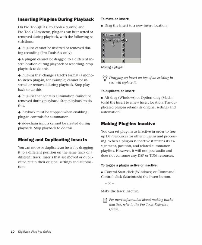
To move an insert:
■ Drag the insert to a new insert location.
To duplicate an insert:
■ Alt-drag (Windows) or Option-drag (Macin-tosh) the insert to a new insert location. The du-plicated plug-in retains its original settings and automation.
Making Plug-Ins Inactive
You can set plug-ins as inactive in order to free up DSP resources for other plug-ins and process-ing. When a plug-in is inactive it retains its as-signment, position, and related automation playlists. However, it will not pass audio and does not consume any DSP or TDM resources.
To toggle a plug-in active or inactive:
■ Control-Start-click (Windows) or Command-Control-click (Macintosh) the Insert button.
– or –
Make the track inactive.
Moving a plug-in
Dragging an insert on top of an existing in-sert will replace it.
For more information about making tracks inactive, refer to the Pro Tools Reference Guide.

To toggle plug-ins in the same insert position on all tracks active or inactive:
■ Control-Start-Alt click (Windows) or Com-mand-Control-Option click (Macintosh) an In-sert button in the position you want to toggle.
To toggle plug-ins in the same insert position on all selected tracks active or inactive:
■ Control-Start-Alt-Shift-click (Windows) or Command-Control-Option-Shift-click (Macin-tosh) an Insert button in the position you want to toggle.
The Plug-In WindowThe Plug-In window appears whenever you click a plug-in Insert button on a track. This floating window lets you set the controls of any real-time plug-in insert in use on a track.
Plug-In window (mono 1-Band EQ shown)
InsertSelector
Settings menu
Track Selector
Librarian menu
Insert PositionSelector
Plug-In Selector
Effect bypass
Compare
Auto button
Insert button Automation Safe
Convert plug-In
Target button
Settings Menu lets you copy, paste, save, and import plug-in settings.
Track Selector Accesses any non-MIDI track in a session.
Librarian Menu Recalls settings files saved in the plug-in’s root settings folder or in the current session’s Settings folder. See “Using the Librar-ian” on page 17.
Insert Position Selector Accesses any insert on the current track.
Plug-In window (multi-mono 1-Band EQ shown)
Plug-In window (multichannel Compressor shown)
Channel Selector
Link Enable buttons
Master Link button
Phase Invert
LFE Enable
Phase Invert buttons
Chapter 3:
W orking with Real-Time Plug-Ins 11
12
Key Input Selector lets you select audio on a par-ticular input or bus and route it to trigger the plug-in. This menu only appears on plug-ins that feature side-chain processing. Key inputs are monophonic.
Plug-In Selector lets you select any real-time plug-in installed in the Plug-Ins folder.
Compare Toggles between the original saved plug-in setting and any changes you have made to it so you can compare them.
Effect Bypass Disables the currently displayed plug-in. This lets you compare the track with and without the effect.
Auto lets you enable individual plug-in controls for automation recording. See “Automating Plug-Ins” on page 16.
Safe When enabled, prevents existing plug-in automation from being overwritten.
Convert Plug-In lets you convert the insert from a TDM plug-in to an RTAS plug-in of the same type (or vice-versa). This feature can only be used on plug-ins that are available in both TDM and RTAS formats.
Target Button When multiple Plug-In windows are open, clicking this button selects that plug-in as the target for any computer keyboard com-mands.
Phase Invert Button Inverts the phase polarity of the input signal on some plug-ins.
Channel Selector Accesses a specific channel within a multichannel track for plug-in control editing. This menu appears only on multi-mono plug-ins inserted on tracks with more than one channel. Shift-clicking this selector opens a sep-arate Plug-In window for each channel of the multichannel track on which the plug-in is in-serted.
DigiRack Plug-Ins Guide
Master Link Button When enabled, links the controls on all channels of a multi-mono plug-in so that they can be adjusted in tandem.
Link Enable Buttons Let you selectively link the controls of specific channels of a multi-mono plug-in. Each square represents a speaker chan-nel. The Master Link button must be disabled to use the Link Enable buttons. See “Linking and Unlinking Controls on Multi-Mono Plug-ins” on page 14.
LFE Enable Enables plug-in processing of the LFE (low frequency effects) channel on a multi-channel track formatted for 5.1, 6.1, or 7.1 sur-round formats on some plug-ins. To disable LFE processing, deselect this button. For more infor-mation on the LFE channel, refer to the Pro Tools Reference Guide.
Opening Plug-In Windows
To open a Plug-In window:
■ Click the plug-in button in the Mix or Edit window channel strip.
By default, each plug-in you open will appear in the same location as a currently open plug-in, replacing it in the same window location.
Opening Multiple Plug-In Windows
Pro Tools normally displays a single Plug-In window from which you can adjust the controls of any plug-in in a session. You can also open additional Plug-In windows for specific plug-ins.
Once you begin working with multiple Plug-In windows, you will need to click the Target but-ton on the plug-in whose controls you want to adjust using keyboard commands.

To open an additional Plug-In window:
■ In the Mix window, Shift-click the Insert but-ton for the additional plug-in.
To open Plug-In windows for each channel of a multi-mono plug-in:
■ Alt-click (Windows) or Option-click (Macin-tosh) the Channel Selector in the Plug-In win-dow of the multi-mono plug-in.
To close all currently open Plug-In windows:
■ Alt-click (Windows) or Option-click (Macin-tosh) the close box of any currently open Plug-In window.
Plug-In Window Controls
All plug-ins provide standard Pro Tools controls for track and insert selection, bypass, and other controls, in addition to plug-in-specific con-trols.
To select a different plug-in on the same track:
■ Click the Insert Selector and select a plug-in from the pop-up menu.
Choosing a plug-in from the Plug-In window
To choose a different track:
■ Click the Track Selector and choose a track from the pop-up menu.
Bypassing Plug-Ins
To bypass a plug-in:
■ Click the Plug-In window’s Bypass button.
– or –
■ Control-click (Windows) or Command-click (Macintosh) the plug-in’s Insert button in the Mix or Edit window.
Choosing a track from the Plug-In window
When a plug-in insert is bypassed, the In-sert Selector in the Mix window changes its color to blue for easy visual reference. If some, but not all channels of an unlinked multi-mono plug-in are bypassed, the Insert Selector appears purple (Pro Tools 6.x) or half blue and half black (Pro Tools 5.x).
Bypass states indicated by color (Pro Tools 6.x)
bypassed (blue)
some channels bypassed (purple)
unbypassed (gray)
Chapter 3: Wo
rking with Real-Time Plug-Ins 13
14
Linking and Unlinking Controls on Multi-Mono Plug-ins
When a multi-mono plug-in is used on a multi-channel track, the controls are normally linked. Adjusting the Gain control on one channel, for example, will adjust it for all channels.
If necessary, you can unlink plug-in controls on specific channels of a track and edit them inde-pendently. You can also selectively link the con-trols of specific channels.
To unlink controls on a multi-mono plug-in:
■ Deselect the Master Link button.
To access controls for a specific channel:
■ Select the channel from the Channel Selector.
To link the controls of specific channels:
1 Deselect the Master Link button if it is not al-ready deselected.
2 Click the Link Enable buttons for the chan-nels whose controls you want to link.
Bypass states indicated by color (Pro Tools 5.3.x)
Channel Selector and Link controls
bypassed (blue)
some channels bypassed (half blue)
unbypassed (black)
Link Enable buttons
Master Link button
Channel Selector
DigiRack Plug-Ins Guide
Editing Plug-In ControlsYou can adjust plug-in controls by dragging the control’s slider or knob, or by typing a value into the control’s text box.
To adjust a plug-in control:
1 Begin audio playback so that you can hear the control changes in real time.
2 Adjust the controls of the plug-in for the effect you want.
3 Closing the plug-in will save the most recent changes.
Keyboard Shortcuts
◆ For finer adjustments, Control-drag (Win-dows) or Command-drag (Macintosh) the con-trol.
◆ To return a control to its default value, Alt-click (Windows) or Option-click (Macintosh) the control.
Keyboard Input for Plug-In Controls
You can use your computer keyboard to edit plug-in controls.
If multiple Plug-In windows are open, Tab and keyboard entry remain focused on the plug-in that is the target window.
To adjust controls from a computer keyboard:
• Click in the control text field that you want to edit to activate the field. Type an appropriate value.
• In fields that support values in kilohertz, typ-ing “k” after a number value will multiply the value by 1,000. For example, type “8k” to en-ter a value of 8,000.

• To increase a value, press the Up Arrow on your keyboard. To decrease a value, press the Down Arrow on your keyboard.
• Press Enter on the numeric keyboard after typ-ing a value to input the value (without leaving the selected control field).
• Press Enter on the alpha keyboard (Windows) or Return (Macintosh) to enter the value and leave keyboard editing mode.
• To move forward through the different con-trol fields, press the Tab key. To move back-ward, press Shift+Tab.
Using a Key Input for Side-Chain ProcessingSome plug-ins, such as the Compressor, Limiter, Gate, and Expander/Gate, feature side-chain processing capabilities. With side-chain process-ing you can trigger a plug-in from a separate ref-erence track or external audio source. The source used for triggering is referred to as the Key Input. Key inputs are monophonic.
A typical use for this feature is to control the dy-namics of one audio signal using the dynamics of another signal (the Key Input). For example, a kick drum track could be used to trigger gating of a bass track to tighten it up, or a rhythm gui-tar track could be used to gate a keyboard pad.
RTAS plug-ins do not provide side-chain processing when used on TDM-based sys-tems. If you want to use side-chain process-ing, use the TDM versions of plug-ins on TDM-based systems.
Key Input Filters
Some plug-ins feature key high-pass and low-pass filters. These controls let you define a spe-cific frequency range in the Key Input signal with which to trigger the plug-in effect. A com-mon production technique is to use these con-trols to filter a drum track so that only specific high frequencies (a hi-hat, for example) or low frequencies (a tom or a kick, for example) trigger the effect.
To use a Key Input for side-chain processing:
1 From the Key Input menu, choose the input or bus carrying the audio you want to use to trig-ger the plug-in.
2 Click External Key to activate side-chain pro-cessing.
3 To hear the audio source you have selected to control side-chain input, click Key Listen.
4 To filter the Key Input so that only specific fre-quencies trigger the plug-in, use the Key HPF and Key LPF controls (if available) to select the desired frequency range.
5 Begin playback. The plug-in uses the input or bus that you chose as a Key Input to trigger its effect.
6 Adjust the plug-in’s Threshold control (if available) to fine-tune Key Input triggering.
7 Adjust other controls to achieve the desired ef-fect.
Choosing a Key Input
Chapter 3: Working with Real-Time Plug-Ins 15

16
Automating Plug-InsYou can automate changes to plug-in controls. Because Pro Tools creates a separate playlist for each plug-in control that you automate, you can later edit and modify each automated control individually. This lets you to build up complex automation in stages.
To enable plug-in controls for automation:
1 Open the Plug-In window for the plug-in you want to automate.
2 Click the Automation Enable button in the Plug-In window.
– or –
Control-Alt-Start-click (Windows) or Com-mand-Option-Control-click the Track View Se-lector in the Edit window.
To create automation for a stereo plug-in with separate controls for each channel, (such as Mod Delay), record the automation for one channel, then copy and paste it to the other channel.
Accessing the Plug-In Automation dialog
You can also use this keyboard shortcut to open the Plug-In Automation dialog. Control-Alt-Start-Right-click (Windows) or Command-Option-Control-click (Macin-tosh) any plug-in control in the Plug-In win-dow, then choose Open Automation Dialog from the pop-up menu.
Plug-In Automation
DigiRack Plug-Ins Guide
3 Choose the controls to automate and click Add. If there are multiple plug-ins on the same track, you can select from among these by click-ing their buttons in the Inserts section of this di-alog.
4 Click OK to close the Plug-In Automation di-alog.
Plug-In automation dialog
As an alternative to using the Plug-In Auto-mation dialog, you can enable individual plug-in controls directly from the Plug-In window by Control-Alt-Start-clicking (Win-dows) or Command-Option-Control-click-ing (Macintosh) the control.
Shortcut for enabling plug-in automation

To automate a plug-in:
1 In the Automation Enable window, make sure plug-in automation is enabled.
2 Select an Automation mode for each track containing plug-ins you want to automate. For the initial automation pass, choose Auto Write.
3 Click Play to begin writing automation, and move the controls you want to automate.
4 When you have finished, click Stop.
After the initial automation pass, you can write additional automation to the track without completely erasing the previous pass by choos-ing Auto Touch mode or Auto Latch mode. These modes add new automation only when you actually move the control.
Record Safing Plug-In Automation
You can protect plug-in automation from being overwritten by using Automation Safe mode.
To enable plug-in safe mode:
1 Open a plug-in.
Automation Enable window
Plug--In Automation Enable button
2 Click the Safe button so that it is highlighted.
To disable plug-in safe mode:
■ In the Plug-In window, click the Safe button so that it is unhighlighted.
Using the LibrarianThe Settings Librarian makes it easy to create your own library of plug-in settings. Using the Librarian and Settings pop-up menus, you can copy, paste, save, and import these settings from plug-in to plug-in, or from session to session.
Once you create and save settings files to disk (and tell Pro Tools where to find them by assign-ing their root folder) they will appear in the Li-brarian menu.
Automation Safe enabled plug-in
For more information on creating and edit-ing automation, refer to the Pro Tools Refer-ence Guide.
Librarian menu
Safe enabled
Chapter 3: Wor
king with Real-Time Plug-Ins 17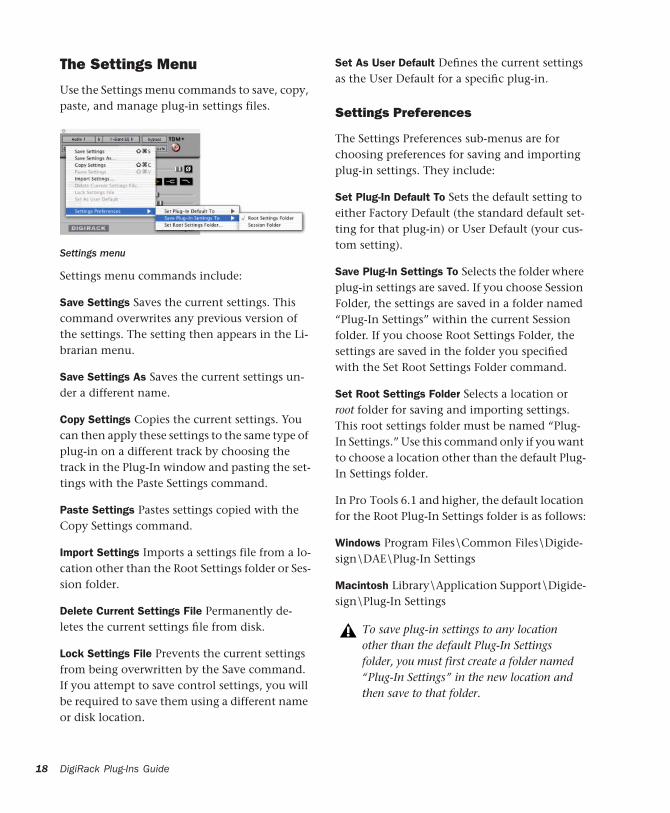
18
The Settings Menu
Use the Settings menu commands to save, copy, paste, and manage plug-in settings files.
Settings menu commands include:
Save Settings Saves the current settings. This command overwrites any previous version of the settings. The setting then appears in the Li-brarian menu.
Save Settings As Saves the current settings un-der a different name.
Copy Settings Copies the current settings. You can then apply these settings to the same type of plug-in on a different track by choosing the track in the Plug-In window and pasting the set-tings with the Paste Settings command.
Paste Settings Pastes settings copied with the Copy Settings command.
Import Settings Imports a settings file from a lo-cation other than the Root Settings folder or Ses-sion folder.
Delete Current Settings File Permanently de-letes the current settings file from disk.
Lock Settings File Prevents the current settings from being overwritten by the Save command. If you attempt to save control settings, you will be required to save them using a different name or disk location.
Settings menu
DigiRack Plug-Ins Guide
Set As User Default Defines the current settings as the User Default for a specific plug-in.
Settings Preferences
The Settings Preferences sub-menus are for choosing preferences for saving and importing plug-in settings. They include:
Set Plug-In Default To Sets the default setting to either Factory Default (the standard default set-ting for that plug-in) or User Default (your cus-tom setting).
Save Plug-In Settings To Selects the folder where plug-in settings are saved. If you choose Session Folder, the settings are saved in a folder named “Plug-In Settings” within the current Session folder. If you choose Root Settings Folder, the settings are saved in the folder you specified with the Set Root Settings Folder command.
Set Root Settings Folder Selects a location or root folder for saving and importing settings. This root settings folder must be named “Plug-In Settings.” Use this command only if you want to choose a location other than the default Plug-In Settings folder.
In Pro Tools 6.1 and higher, the default location for the Root Plug-In Settings folder is as follows:
Windows Program Files\Common Files\Digide-sign\DAE\Plug-In Settings
Macintosh Library\Application Support\Digide-sign\Plug-In Settings
To save plug-in settings to any location other than the default Plug-In Settings folder, you must first create a folder named “Plug-In Settings” in the new location and then save to that folder.
Choosing a Destination for Settings
Before you save plug-in settings, select their des-tination folder.
To select a destination folder:
■ From the Settings pop-up menu, choose Set-tings Preferences > Save Plug-In Settings To, and choose Session Folder or Root Settings Folder.
If you choose Root Settings folder, Pro Tools saves to the default Root Plug-In Settings folder unless you have specified a different location for the Root Settings folder.
To select a different Root Settings folder:
1 From the Settings pop-up menu, choose Set-tings Preferences > Set Root Settings Folder.
2 Select the folder you want to use as your Root folder and click Select.
Managing Settings
Use the Settings pop-up menu to manage set-tings.
To save a setting:
1 Choose Save Settings from the Settings pop-up menu.
2 Type a name and click OK. The setting appears in the Librarian menu.
Unlinked multi-mono plug-ins have specific rules for settings. See “Editing Settings on Unlinked Multi-Mono Plug-ins” on page 20.
Press Control+Shift+S (Windows) or Com-mand+Shift+S (Macintosh) to save plug-in settings.
To load a previously saved setting:
■ Choose the setting from the Librarian pop-up menu.
To import a setting:
1 Choose Import Settings from the Settings pop-up menu.
2 Locate the settings file you want to import and click Open. Pro Tools loads the setting and copies it to the root destination folder.
To copy a setting:
■ Choose Copy Settings from the Settings pop-up menu.
To paste a setting:
1 Open the destination plug-in.
2 Choose Paste Settings from the Settings pop-up menu.
To create a custom User Default setting:
1 Create and save a setting.
2 Choose Set As User Default from the Settings pop-up menu.
To make a plug-in default to your custom setting:
■ From the Settings pop-up menu, choose Set Plug-In Default To > User Setting.
Press Control+Shift+C (Windows) or Com-mand+Shift+C (Macintosh) to copy plug-in settings.
Press Control+Shift+V (Windows) or Com-mand+Shift+V (Macintosh) to paste plug-in settings.
Chapter 3: Working with Real-Time Plug-Ins 19

20
Editing Settings on Unlinked Multi-Mono Plug-ins
When a multi-mono plug-in is unlinked, im-porting, copying, pasting, or bypassing settings affects only the currently selected channel.
To apply an operation to all channels of an unlinked plug-in:
■ Hold down the Alt key (Windows) or Option key (Macintosh) while performing the com-mand.
Creating Subfolders for Settings
To make it easier to find specific types of set-tings, you can subdivide settings files by creat-ing subfolders for them.
To create a settings subfolder:
1 From the Settings pop-up menu, choose Save Settings.
2 Click the New Folder button and type a name for the subfolder.
3 Name the setting and click Save. The setting is saved within the subfolder.
Librarian menu with subfolders for settings
DigiRack Plug-Ins Guide

chapter 4
Working with AudioSuite Plug-Ins
AudioSuite plug-ins differ from TDM and RTAS plug-ins in that they are used to process and modify audio files on disk rather than nonde-structively in real time. Depending on how you configure a non-real-time AudioSuite plug-in, it will either alter the original source audio file or create an entirely new audio source file.
AudioSuite plug-ins are accessed through the AudioSuite menu.
AudioSuite menu
AudioSuite Plug-Ins
1-Band EQ II Processes audio with high-pass, low-shelf, high-shelf, low-pass or peak EQ filters, in a 1-band module.
4-Band EQ II Processes audio with high-pass, low-shelf, high-shelf, low-pass or peak EQ filters, in a 4-band module.
Click Creates an audio click as a tempo reference for performing and recording.
Compressor Processes audio with compression.
Chorus Processes audio with chorusing.
Flanger Processes audio with flanging.
LImiter Processes audio with limiting.
Gate Processes audio with gating.
Expander Gate Processes audio with expander-gating.
De-esser Processes audio with de-essing to re-move sibilance.
Duplicate Creates a new, continuous source au-dio file (and region) from the selection.
Delay Adds up to 10.9 seconds of delay.
Multi-tap Delay Adds up to four independently-controllable delays to the original audio signal.
Chapter 4: Working with AudioSuite Plug-Ins 21

22
Normalize Uniformly adjusts all levels in a re-gion or regions to a user-definable level, using the loudest peak in the audio file as the refer-ence.
Ping-Pong Delay Adds a stereo, ping-pong delay to the audio signal by feeding back the original signal to its opposite channel.
Gain Adjusts gain (volume) change, in decibels or percentage before clip.
Invert Inverts phase (polarity).
Pitch Shift Changes an audio file’s pitch with or without changing its duration.
Reverse Rewrites selected audio in reverse.
DC Offset Removal Recognizes and removes DC offset from audio files.
Signal Generator Generates audio tones for equipment calibration purposes.
Time Compression/Expansion Changes an audio file’s duration with or without changing its pitch.
DigiRack Plug-Ins Guide
The AudioSuite WindowWhen you choose a plug-in from the AudioSuite menu, the AudioSuite window ap-pears. From this floating window you can access and edit the controls for any non-real-time Au-dioSuite plug-in.
Plug-In Selector
From this menu you can select any AudioSuite plug-in installed in your Plug-Ins folder.
AudioSuite window
Plug-In Selector menu
File ModeSelector
Plug-InSelector
Bypass
Processmode
Selectionreference
Processbutton
Previewbutton
Use In Playlist button
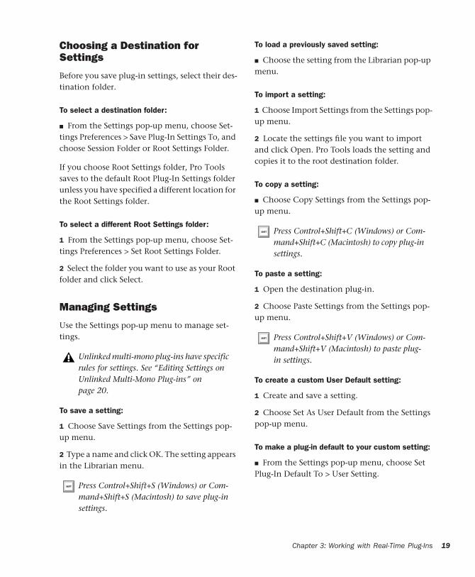
Selection Reference
This menu aims the selected process at either re-gions selected in an audio track or playlist, or at regions selected in the Audio Regions List.
When you select a region on-screen (in either a track/playlist or the Region List) Pro Tools nor-mally selects both occurrences of the region. Since you may not want to process both, this menu provides a convenient means of limiting the AudioSuite process to regions selected in one or the other.
Playlist Applies AudioSuite processing only to regions currently selected in tracks/playlists in the Edit window. Processing will not be applied to regions in the Audio Regions List.
Region List Applies AudioSuite processing only to regions currently selected in the Audio Re-gions List. Processing will not be applied to re-gions located in tracks and playlists in the Edit window.
Selection Reference pop-up menu
If the Use In Playlist option is enabled in addition to Region List being selected in the Selection Reference pop-up menu, the pro-cessing will be applied to the selected region in both the playlist and the Regions List.
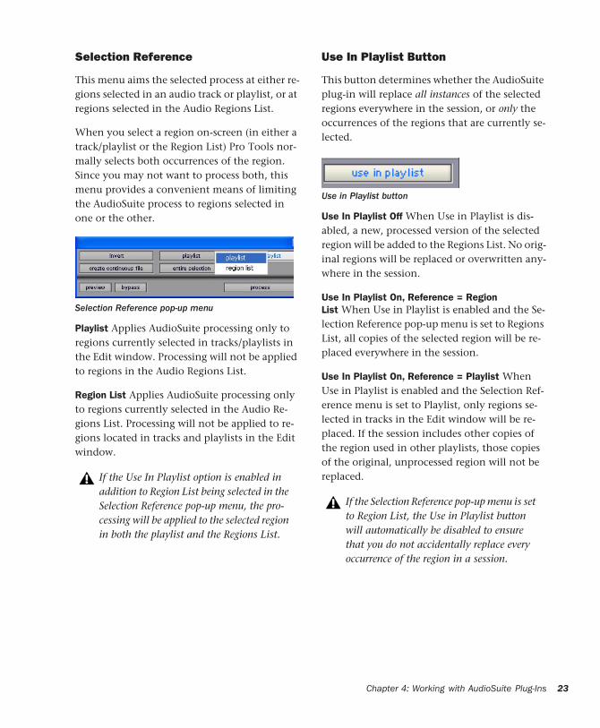
Use In Playlist Button
This button determines whether the AudioSuite plug-in will replace all instances of the selected regions everywhere in the session, or only the occurrences of the regions that are currently se-lected.
Use In Playlist Off When Use in Playlist is dis-abled, a new, processed version of the selected region will be added to the Regions List. No orig-inal regions will be replaced or overwritten any-where in the session.
Use In Playlist On, Reference = Region List When Use in Playlist is enabled and the Se-lection Reference pop-up menu is set to Regions List, all copies of the selected region will be re-placed everywhere in the session.
Use In Playlist On, Reference = Playlist When Use in Playlist is enabled and the Selection Ref-erence menu is set to Playlist, only regions se-lected in tracks in the Edit window will be re-placed. If the session includes other copies of the region used in other playlists, those copies of the original, unprocessed region will not be replaced.
Use in Playlist button
If the Selection Reference pop-up menu is set to Region List, the Use in Playlist button will automatically be disabled to ensure that you do not accidentally replace every occurrence of the region in a session.
Chapter 4: Working with AudioSuite Plug-Ins 23

24
File Mode Selector
From this menu you can select whether or not the AudioSuite plug-in will process the selected audio destructively or non-destructively, and how the original files will be modified.
There are three options:
Overwrite Files Processes the selected regions de-structively, overwriting the original audio. Not all AudioSuite plug-ins can be used destruc-tively.
Create Individual Files Processes the selected re-gions nondestructively, creating a new audio file for each region. The new audio files are added to the session, leaving the original source audio files in the Regions List unchanged. (Whether the processed audio is added to the current playlist or only to the Regions List, is de-termined by the Selection Reference setting, as explained earlier.)
Create Continuous File Processes the selected re-gions nondestructively and creates a new audio file consisting of the selected regions consoli-dated into a single, unbroken region. This mode is particularly useful if you are assembling a composite track from multiple takes. This mode is not available when the Selection Reference is set to Region List.
File Mode pop-up menu
The Create Continuous File option is not available with some time domain plug-ins. To achieve a similar result, use the Dupli-cate plug-in to consolidate regions processed with these plug-ins.
DigiRack Plug-Ins Guide
Process Mode Selector
If you have made a selection that includes mul-tiple regions, this pop-up menu lets you specify whether AudioSuite processing is performed on a region-by-region, or entire-selection basis.
Region by Region Analyzes each region in a se-lection individually, rather than over the entire multi-region selection as a whole.
Entire Selection Uses the entire selection for analysis. All regions will be analyzed and pro-cessed relative to the entire selection.
Chan/Track Process Mode Selector
If you have made a selection that includes re-gions from multiple tracks, the Normalize AudioSuite plug-in (as well as some third-party AudioSuite plug-ins) lets you choose whether you want to perform processing on a channel-by-channel/track-by-track, or an all-chan-nel/all-tracks basis using the Chan/Track Process Mode Selector.
Process Mode Selector
Chan/Track Process Mode Selector pop-up menu

Peak On Each Chan/Track Analyzes and pro-cesses each selected track individually. If you ap-ply the Normalize plug-in to multiple tracks or a multichannel track in Peak On Each Chan/Track mode, each channel or track will be normalized independently, without regard to the other se-lected tracks.
Peak On All Chans/Tracks Uses all currently se-lected channels and tracks for analysis. If you apply the Normalize plug-in to a multichannel track or multiple tracks in Peak On All Chans/Tracks mode, the tracks will be analyzed as a single entity and regions will be normalized relative to the averaged peak level within all se-lected channels and tracks.
Preview
The Preview button lets you audition the effect of a plug-in before you process the audio. By ad-justing the plug-in controls while you listen to this audio preview, you can fine-tune the effect. Not all AudioSuite plug-ins support this feature.
The Preview function routes audio to the spe-cific outputs you have chosen with the Audition pop-up menu in the Outputs page of the I/O Setup dialog. Make sure you have config-ured this option correctly for your system or you may not be able to hear previewed audio.
For more information on using the I/O Setup dialog to configure your system’s au-dio outputs, refer to the Pro Tools Reference Guide.
Before you use Preview, be aware that:
◆ The performance of the Preview function de-pends on the speed of your CPU. Faster comput-ers preview AudioSuite effects better than slower computers.
◆ Regardless of how many tracks and regions are currently selected, the Preview button will audition only the first selected stereo track or the first selected pair of mono tracks.
◆ If you are using Region-by-Region processing mode, the Preview function will preview only the first region within a multi-region selection. To hear all selected regions, temporarily select Create Continuous File from the File Mode menu before previewing.
◆ The Preview function is affected by the AudioSuite Buffer Size option (on the Processing page of the Pro Tools Preferences dialog). See “The AudioSuite Processing Preferences Dialog” on page 27.
Bypass
When Bypass is enabled, the selected audio is auditioned without AudioSuite processing. The Bypass button applies only to previewing. It does not affect actual AudioSuite processing.
Process
Clicking this button begins AudioSuite process-ing of the selected audio. Processing can occur during playback (though it may take slightly longer). Processed files are auto-named with the region or audio file’s name plus an acronym for the chosen AudioSuite process.
New files are written to the hard disk specified for that track in the Disk Allocation dialog, or to the same drive as the original file if the region is not currently on a track. See “Auto-File Naming of AudioSuite-Processed Audio” on page 26.
Chapter 4: Working with AudioSuite Plug-Ins 25

26
Multichannel Processing
Most DigiRack AudioSuite plug-ins can process up to 48 channels of audio simultaneously.
Undoing AudioSuite Processing
If you have processed an audio selection nonde-structively, the Undo and Redo commands let you undo the selected AudioSuite process. You can undo or redo an AudioSuite process during audio playback.
Auto-File Naming of AudioSuite-Processed Audio
When new audio files are created as a result of AudioSuite processing, Pro Tools will auto-name these files according to the type of plug-in used. The name of the region determines the prefix, while the type of AudioSuite plug-in determines the suffix.
When processing multiple regions of differ-ent formats (mono and multichannel sur-round, for example), all channels will be processed according to the channel format of the AudioSuite plug-in. Mono AudioSuite plug-ins can process stereo regions and ste-reo AudioSuite plug-ins can process mono regions.
Undo is not available when a plug-in is con-figured for destructive editing since the pro-cess has already overwritten the source au-dio file.
DigiRack Plug-Ins Guide
Auto file-naming follows these rules:
◆ New regions are named beginning with the region name, followed by an abbreviation of the current AudioSuite process, followed by stan-dard Pro Tools file and region numbering.
◆ If a plug-in’s File Mode pop-up is set to Over-write, the original region’s name will not be changed.
◆ If a plug-in’s File Mode pop-up is set to Create Individual Files, the resulting regions will have an abbreviated version of the plug-in name ap-pended to them.
Other AudioSuite Controls
In addition to the standard AudioSuite controls, there are a number of special-purpose controls found on certain plug-ins:
Plug-In Librarian and Settings Menus The Set-tings and Librarian pop-up menus that appear in some AudioSuite plug-ins provide a means of saving, loading, copying, pasting and organiz-ing custom plug-in settings files. See “Using the Librarian” on page 17.
Analyze Button Analyzes a selection without ac-tually processing it. On the DigiRack Gain plug-in, you can use the Analyze feature to determine the maximum peak level on a track at a specific gain value before you process the audio.
Side-chain Input Selector Selects a track/bus to be used to trigger processing. In order to use this feature, the key input source audio must occur at the same time as the target audio. Side-chain input is monophonic. See “Using a Key Input for Side-Chain Processing” on page 15.
Side-chain inputs for plug-ins have no effect on AudioSuite processes when the Selection Reference is set to Region List.
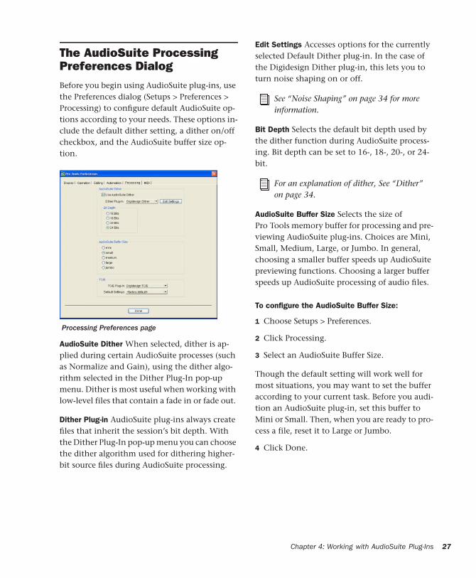
The AudioSuite Processing Preferences DialogBefore you begin using AudioSuite plug-ins, use the Preferences dialog (Setups > Preferences > Processing) to configure default AudioSuite op-tions according to your needs. These options in-clude the default dither setting, a dither on/off checkbox, and the AudioSuite buffer size op-tion.
AudioSuite Dither When selected, dither is ap-plied during certain AudioSuite processes (such as Normalize and Gain), using the dither algo-rithm selected in the Dither Plug-In pop-up menu. Dither is most useful when working with low-level files that contain a fade in or fade out.
Dither Plug-in AudioSuite plug-ins always create files that inherit the session’s bit depth. With the Dither Plug-In pop-up menu you can choose the dither algorithm used for dithering higher-bit source files during AudioSuite processing.
Processing Preferences page
Edit Settings Accesses options for the currently selected Default Dither plug-in. In the case of the Digidesign Dither plug-in, this lets you to turn noise shaping on or off.
Bit Depth Selects the default bit depth used by the dither function during AudioSuite process-ing. Bit depth can be set to 16-, 18-, 20-, or 24-bit.
AudioSuite Buffer Size Selects the size of Pro Tools memory buffer for processing and pre-viewing AudioSuite plug-ins. Choices are Mini, Small, Medium, Large, or Jumbo. In general, choosing a smaller buffer speeds up AudioSuite previewing functions. Choosing a larger buffer speeds up AudioSuite processing of audio files.
To configure the AudioSuite Buffer Size:
1 Choose Setups > Preferences.
2 Click Processing.
3 Select an AudioSuite Buffer Size.
Though the default setting will work well for most situations, you may want to set the buffer according to your current task. Before you audi-tion an AudioSuite plug-in, set this buffer to Mini or Small. Then, when you are ready to pro-cess a file, reset it to Large or Jumbo.
4 Click Done.
See “Noise Shaping” on page 34 for more information.
For an explanation of dither, See “Dither” on page 34.
Chapter 4: Working with AudioSuite Plug-Ins 27

28
TC/E Selects the Time Compression & Expan-sion plug-in and default settings used when ed-iting with the Time Trimmer tool. If you own a compatible third-party time compression and expansion plug-in, you have the option of using it for Pro Tools time compression and expan-sion processes by selecting it here.
Using AudioSuite Plug-InsAudioSuite plug-ins can be applied to whole re-gions, partial regions, or selections that are made up of whole and partial regions across one or more tracks.
When audio selected in the Edit window in-cludes partial regions, the regions will automat-ically be split into two or more regions when they are processed. Processing will occur only on the selection, leaving other regions un-changed.
Only audio files on locally connected hard drives can be processed with AudioSuite plug-ins. You cannot process audio files on remote hard drives over a network (unless it is a Unity network).
Refer to the Pro Tools Reference Guide for more information about the Time Trimmer tool.
Processing a locked region will cause the re-gion to become unlocked, and processing a muted region will cause it to become un-muted. For more information on locked and muted regions, refer to the Pro Tools Refer-ence Guide.
DigiRack Plug-Ins Guide
Selecting Tracks for AudioSuite Processing
Because AudioSuite processes are performed on the specific regions that you select, it is impor-tant that you select only those regions, or parts of regions, you actually want to process.
Selecting a region in the Audio Regions List will automatically select it in a track (if it currently resides on one). This is the default behavior for Pro Tools. However, you can change this using the Region Selection Follows Track Selection, or Track Selection Follows Regions List Selection options in the Editing page of the Preferences di-alog. Refer to the Pro Tools Reference Guide for an explanation of these Preferences.
Selecting Tracks for Delay or Reverb Processing
Because some AudioSuite effects such as delay and reverb add additional material to the end of the selected audio (a reverb tail or a delay tap), it is very important that you make a selection that is longer than the original source material so that the plug-in can write it into the audio file.
If you select only the original material, without leaving additional space at the end, a reverb de-cay or delay that occurs after the end of the re-gion will be cut off.
To compensate for this, place the region in a track and select the desired audio plus an amount of blank space at the end of the region equal to the amount of delay or reverb decay that you have added in the plug-in. The plug-in will then have space at the end of the region in which to write the final delay or decay.
When processing a single audio channel with an AudioSuite plug-in, make sure that the plug-in is set to Mono mode (if avail-able).

If you select more blank space than you need, you can remove it using the Trim tool after ap-plying AudioSuite processing.
To process audio with an AudioSuite plug-in:
1 Select regions to process in one or more target tracks and/or in the Audio Regions List. Shift-click to select multiple regions. Only regions that are selected will be processed.
2 Choose the desired AudioSuite plug-in from the AudioSuite menu.
3 Click the Preview button to begin playback of the selected material.
4 Adjust the plug-in controls to achieve the ef-fect that you want. These settings will determine how the file is processed and what effect the processing will have on the original regions. Fol-low these guidelines:
• To process the selected region only in the track in which it appears, select Playlist from the Selection Reference pop-up. Alter-natively, if you want to process the selected region in the Audio Regions list only, choose Region List from this pop-up.
• If you want to process and update every oc-currence of the selected region throughout your session, enable the Use In Playlist but-ton (and also select Region List from the Se-lection Reference pop-up). Alternatively, if you do not want to update every occur-rence of the selected region, deselect the Use In Playlist button.
• To configure the plug-in for destructive processing, select Overwrite Files from the File Mode pop-up menu. This will over-write and permanently modify the original source audio files.
• Alternatively, to configure the plug-in for nondestructive processing, select Create Individual Files from the File Mode pop-up menu. This will create new audio files that have been processed with the AudioSuite Plug-in and leave the original source audio files untouched.
• If you have selected multiple regions for processing and want to create a new file that connects and consolidates all of these regions together, select Create Continuous File from the File Mode pop-up menu.
5 Finally, when you are ready, click the Process button.
The selected audio is processed according to the settings you have specified. Pro Tools appends an acronym to the region’s name indicating the AudioSuite process that has been applied. The new audio files then appear in your session.
Using AudioSuite Plug-Ins in Stereo
Some AudioSuite plug-ins can be used in either mono or stereo. If you plan to use them in ste-reo, be aware of the following:
◆ To process a mono track and obtain a stereo result, select the desired track or region plus an empty track or region. Then set the plug-in to Stereo mode and select the Sum Inputs button (if present) to center the dry signal. When you process the audio, the result will be two tracks or regions that represent the right and left chan-nels of the processed audio. You should then pan these tracks hard right and hard left in your mix.
◆ If you set a plug-in to Stereo mode, then select an odd number of Pro Tools tracks for process-ing (as opposed to an even number), the plug-in will process the selected tracks in pairs, in stereo. However, the last odd, unpaired track will be
Chapter 4: Working with AudioSuite Plug-Ins 29

30
processed as mono, using the left channel set-tings of the stereo plug-in. If you want the last track to be processed in stereo, you must select an additional track to pair it with—an empty one if necessary.
DigiRack Plug-Ins Guide

chapter 5
DigiRack Real-Time TDM and RTAS Plug-Ins
EQ IIThe EQ II plug-in provides a 1-Band or 4-Band EQ for adjusting the frequency spectrum of an audio selection. You can configure the 1-Band EQ as a high-pass, low-shelf, high-shelf, low-pass, or peak EQ. The 4-Band EQ provides one high-shelf, one low-shelf, and two peak EQs.
1-Band EQ plug-in
Phase Invert
High-Pass
Low-Shelf
Peak
High-Shelf
Low-Pass
4-Band EQ plug-in
Phase Invert
Low-Shelf High-ShelfPeak
Chapter 5: DigiRack Real-Time TDM and RTAS Plug-Ins 31

32
Adjusting EQ
A useful way to audition an EQ is to increase or decrease its gain several dB then sweep the fre-quency up or down until you hear its effect. You can then make more precise adjustments to the settings.
EQ II Controls
Input Controls the input gain of the EQ, letting you prevent clipping. Since Pro Tools inserts are pre-fader, plug-ins used as inserts can cause clip-ping if their levels are boosted excessively.
Phase Invert Inverts the phase (polarity) of the input signal to change frequency response char-acteristics between multi-miked sources or to correct for miswired microphone cables.
Type Selects an EQ type (high-pass, low-shelf, peak, high-shelf or low-pass).
Freq Designates the center of the frequency re-gion to be cut or boosted.
Gain Controls the amount that the selected fre-quencies are cut or boosted.
Q Sets the bandwidth of the Peak filter. Higher values represent narrower bandwidths. Lower numbers represent wider bandwidths. This con-trol is only available on the Peak EQ.
Phase Invert
DigiRack Plug-Ins Guide
Bypass Bypasses the EQ. The 4-Band EQ has in-dividual Bypass buttons for each band (the black buttons with appropriate EQ curve icons), as well as the standard all-band Bypass button at the top of the Inserts/Sends Editor window.
High-Pass Filter Attenuates all frequencies below the selected cutoff frequency setting at a rate of 12 dB per octave while letting all others above pass through. For this reason, no gain control is available for this filter. High-Pass filters can be useful for removing low frequency rumble or thinning out the lower end of a sound for spe-cial effects such as simulating a telephone effect.
Low-Shelf EQ Produces a lift or a cut at and be-low the specified frequency.
Peak EQ Boosts or cuts only those frequencies centered around the selected center frequency. The Q button sets the bandwidth of the Peak fil-ter. This determines the width of the filter’s overall slope—from a broad bell shape to a nar-row notch. Broad curves tend to be most useful for musical applications. Narrow curves are use-ful for special purpose processing such as hum removal. Higher values represent narrower bandwidths. Lower numbers represent wider bandwidths.
High-Shelf EQ Produces a lift or a cut at and above the specified frequency.
Low-Pass filter Attenuates all frequencies above the selected cutoff frequency setting at a rate of 12 dB per octave while letting all others below pass through. For this reason, no gain control is available for this filter.
Bypass EQ band button on the 4-band EQ
Click(Pro Tools 6.x)
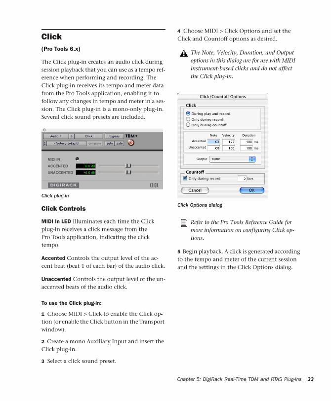
The Click plug-in creates an audio click during session playback that you can use as a tempo ref-erence when performing and recording. The Click plug-in receives its tempo and meter data from the Pro Tools application, enabling it to follow any changes in tempo and meter in a ses-sion. The Click plug-in is a mono-only plug-in. Several click sound presets are included.
Click Controls
MIDI In LED Illuminates each time the Click plug-in receives a click message from the Pro Tools application, indicating the click tempo.
Accented Controls the output level of the ac-cent beat (beat 1 of each bar) of the audio click.
Unaccented Controls the output level of the un-accented beats of the audio click.
To use the Click plug-in:
1 Choose MIDI > Click to enable the Click op-tion (or enable the Click button in the Transport window).
2 Create a mono Auxiliary Input and insert the Click plug-in.
3 Select a click sound preset.
Click plug-in
4 Choose MIDI > Click Options and set the Click and Countoff options as desired.
5 Begin playback. A click is generated according to the tempo and meter of the current session and the settings in the Click Options dialog.
The Note, Velocity, Duration, and Output options in this dialog are for use with MIDI instrument-based clicks and do not affect the Click plug-in.
Click Options dialog
Refer to the Pro Tools Reference Guide for more information on configuring Click op-tions.
Chapter 5: DigiRack Real-Time TDM and RTAS Plug-Ins 33

34
DitherThe Dither plug-in is designed for reducing quantization noise when mixing or fading low-level audio signals during word size reduction to 16-, 18-, or 20-bits.
Dither is a form of randomized noise used to minimize quantization artifacts in digital audio systems. Quantization artifacts are most audible when the audio signal is near the low end of its dynamic range, such as during a quiet passage or fade-out.
The introduction of dithering can reduce these quantization artifacts with very low-level noise, minimizing artifacts as audio reaches low level. With dithering there is a trade-off between sig-nal-to-noise performance and less-apparent arti-facts. Proper use of dithering squeezes better subjective performance out of 16-bits (or what-ever the destination bit-depth).
The most common application of dithering is to use it on a master output mix as the last proces-sor in the signal path when preparing a 24-bit session for CD mastering. In this case, you
For more advanced dithering, use the Digi-Rack POW-r Dither plug-in. See “POW-r Dither” on page 35.
Dither plug-in
DigiRack Plug-Ins Guide
would insert the Dither plug-in on a Master Fader to reduce session bit-depth from 24-bits to 16-bits. The inserts on a Master Fader track are always post-fader.
The Dither plug-in has user-selectable bit resolu-tion and a noise shaping on/off option.
Noise Shaping
The Dither plug-in features a technique known as noise shaping to further improve audio per-formance and reduce perceived noise in low-level signals. Noise shaping utilizes filtering to reduce noise that falls in the middle of the audio spectrum (specifically, around 4 kHz). This is the range where human hearing is most sensitive.
In reality, since the noise plays an important role in reducing quantization artifacts, the noise is not reduced, rather it is shifted into a fre-quency range where it is harder to hear. Essen-tially, noise shaping lessens our perception of the noise inherent in dithering schemes by shifting audible noise components into a less audible range.
Insert the Dither plug-in (or any dithering plug-in, such as Dither, POW-r Dither, or Maxim) on a Master Fader track when us-ing Bounce to Disk to create a 16-bit file (or any bit depth lower than 24-bit) from a 24-bit session; otherwise the resulting 16-bit file will be “truncated” at the destination bit depth. For more information on Bounce to Disk, refer to the Pro Tools Reference Guide.
If outputting 24-bit audio to an analog des-tination with a 96 I/O, or 192 I/O, you do not need to use Dither. This allows maxi-mum output fidelity from the high-perfor-mance 24-bit digital-to-analog convertors of the interfaces.

Dither and Output Bit Resolution
Dither has two user-selectable settings for opti-mizing its operation:
Bit Resolution
Use this pop-up menu to choose one of three possible resolutions for the Dither processing. As a general rule, set this control to the maxi-mum bit resolution of your destination.
16-bit Recommended for output to digital de-vices such as DAT recorders and CD recorders, since they have a maximum resolution of 16-bits.
18-bit Recommended for output to analog de-vices if you are using an 18-bit audio interface, such as the 888 I/O or 882 I/O audio interface; this is the maximum resolution available from the 18-bit digital-to-analog convertors of these devices.
20-bit Recommended for output to digital de-vices that support a full 20-bit recording data path, such the Sony PCM-9000 optical master-ing recorder, or the Alesis ADAT XT 20. Use this setting for output to analog devices if you are us-ing a 20-bit audio interface, such as the 882|20 I/O audio interface. The 20-bit setting can also be used for output to digital effects de-vices that support 20-bit input and output, since it provides for a lower noise floor and greater dy-namic range when mixing 20-bit signals directly into the TDM environment.
If you want, you can choose not to use the Dither plug-in and instead utilize the full 24-bit resolution of Pro Tools’ digital output, depend-ing on your destination device. As noted previ-ously, if you are using a 24-bit audio interface (such as the 192 I/O, 96 I/O, or 888|24 I/O) and are outputting audio to an analog destination, we recommend that you do not use dither.
Noise Shape
This button engages or disengages Noise Shap-ing. Noise shaping is on when the button is highlighted in blue. See “Noise Shaping” on page 34 for more information.
POW-r DitherThe POW-r Dither plug-in is an advanced type of dither that provides optimized word length reduction. It is designed for final-stage critical mixdown and mastering tasks where the highest possible fidelity is desired when reducing bit depth. For more information on dithering, see “Dither” on page 34.
The DigiRack Dither plug-in only provides eight channels of uncorrelated dithering noise. If DigiRack Dither is used on more than eight tracks, the dithering noise begins to repeat and dither performance is im-paired. For example, if two Quad DigiRack Dithers are used, both Quad instances of Dither will have all of their dither noise un-correlated. However, any additional in-stances of the Dither plug-in will begin to repeat the dithering noise.
Refer to the Pro Tools Reference Guide for details on using the Dither plug-in during mixdown.
POW-r Dither plug-in
Chapter 5: DigiRack Real-Time TDM and RTAS Plug-Ins 35

36
POW-r Dither Controls
Bit Resolution
Use this pop-up menu to choose either 16- or 20-bit resolutions for POW-r Dither processing. Set this control to the maximum bit resolution of your destination.
16-bit Recommended for output to devices with a maximum resolution of 16-bits, such as DAT and CD recorders.
20-bit Recommended for output to devices that support a full 20-bit recording data path.
Noise Shaping
Noise shaping improves audio performance and lessens our perception of the noise inherent in dithering schemes by shifting audible noise components into a less audible range.
The POW-r Dither plug-in provides three types of noise shaping, each with its own characteris-tics.
The POW-r Dither plug-in does not run on third party software applications that use DAE.
The multichannel TDM version of the POW-r Dither plug-in is not supported at 192 kHz, use the multi-mono TDM or RTAS version instead.
The POW-r Dither plug-in is not appropri-ate for truncation stages that are likely to be further processed. It is recommended that POW-r Dither be used only as the last insert in the signal chain (especially when using Type 1 Noise Shaping).
DigiRack Plug-Ins Guide
It is recommended that you try each noise shap-ing type and choose the one that adds the least amount of coloration to the audio being pro-cessed.
Type 1 Has the flattest frequency spectrum in the audible range of frequencies, modulating and accumulating the dither noise just below the Nyquist frequency. Recommended for less stereophonically complex material such as solo instrument recordings.
Type 2 Has a psychoacoustically optimized low order noise shaping curve. Recommended for material of greater stereophonic complexity.
Type 3 Has a psychoacoustically optimized high order noise shaping curve. Recommended for full-spectrum, wide-stereo field material.
Refer to the Pro Tools Reference Guide for details on using the Dither plug-in during mixdown.
On DSP Farm-equipped MIX-series sys-tems, POW-r Dither requires more than one DSP chip when used on LCR and beyond multichannel tracks. On MIX Farm equipped MIX-series systems, POW-r Dither requires more than one DSP chip when used on 7.0-format and beyond mul-tichannel tracks.
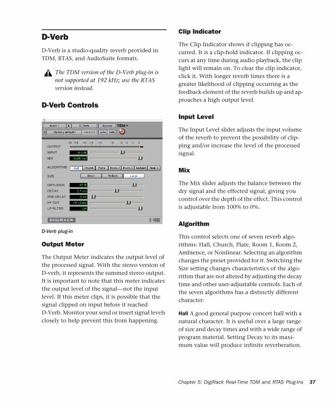
D-VerbD-Verb is a studio-quality reverb provided in TDM, RTAS, and AudioSuite formats.
D-Verb Controls
Output Meter
The Output Meter indicates the output level of the processed signal. With the stereo version of D-verb, it represents the summed stereo output. It is important to note that this meter indicates the output level of the signal—not the input level. If this meter clips, it is possible that the signal clipped on input before it reached D-Verb. Monitor your send or insert signal levels closely to help prevent this from happening.
The TDM version of the D-Verb plug-in is not supported at 192 kHz; use the RTAS version instead.
D-Verb plug-in
Clip Indicator
The Clip Indicator shows if clipping has oc-curred. It is a clip-hold indicator. If clipping oc-curs at any time during audio playback, the clip light will remain on. To clear the clip indicator, click it. With longer reverb times there is a greater likelihood of clipping occurring as the feedback element of the reverb builds up and ap-proaches a high output level.
Input Level
The Input Level slider adjusts the input volume of the reverb to prevent the possibility of clip-ping and/or increase the level of the processed signal.
Mix
The Mix slider adjusts the balance between the dry signal and the effected signal, giving you control over the depth of the effect. This control is adjustable from 100% to 0%.
Algorithm
This control selects one of seven reverb algo-rithms: Hall, Church, Plate, Room 1, Room 2, Ambience, or Nonlinear. Selecting an algorithm changes the preset provided for it. Switching the Size setting changes characteristics of the algo-rithm that are not altered by adjusting the decay time and other user-adjustable controls. Each of the seven algorithms has a distinctly different character:
Hall A good general purpose concert hall with a natural character. It is useful over a large range of size and decay times and with a wide range of program material. Setting Decay to its maxi-mum value will produce infinite reverberation.
Chapter 5: DigiRack Real-Time TDM and RTAS Plug-Ins 37

38
Church A dense, diffuse space simulating a church or cathedral with a long decay time, high diffusion, and some pre-delay.
Plate Simulates the acoustic character of a metal plate-based reverb. This type of reverb typically has high initial diffusion and a rela-tively bright sound, making it particularly good for certain percussive signals and vocal process-ing. Plate reverb has the general effect of thick-ening the initial sound itself.
Room 1 A medium-sized, natural, rich-sounding room that can be effectively varied in size be-tween very small and large, with good results.
Room 2 A smaller, brighter reverberant charac-teristic than Room 1, with a useful adjustment range that extends to “very small.”
Ambient A transparent response that is useful for adding a sense of space without adding a lot of depth or density. Extreme settings can create in-teresting results.
Nonlinear Produces a reverberation with a natu-ral buildup and an abrupt cutoff similar to a gate. This unnatural decay characteristic is par-ticularly useful on percussion, since it can add an aggressive characteristic to sounds with strong attacks.
Size
The Size control, in conjunction with the Algo-rithm control, adjusts the overall size of the re-verberant space. There are three sizes: Small, Medium, and Large. The character of the rever-beration changes with each of these settings (as does the relative value of the Decay setting). The Size buttons can be used to vary the range of a reverb from large to small. Generally, you should select an algorithm first, and then choose the size that approximates the size of the acoustic space that you are trying to create.
DigiRack Plug-Ins Guide
Diffusion
Diffusion sets the degree to which initial echo density increases over time. High settings result in high initial build-up of echo density. Low set-tings cause low initial buildup. This control in-teracts with the Size and Decay controls to affect the overall reverb density. High settings of diffu-sion can be used to enhance percussion. Use low or moderate settings for clearer and more natu-ral-sounding vocals and mixes.
Decay
Decay controls the rate at which the reverb de-cays after the original direct signal stops. The value of the Decay setting is affected by the Size and Algorithm controls. This control can be set to infinity on most algorithms for infinite re-verb times.
Pre-Delay
Determines the amount of time that elapses be-tween the original audio event and the onset of reverberation. Under natural conditions, the amount of Pre-Delay depends on the size and construction of the acoustic space, and the rela-tive position of the sound source and the lis-tener. Pre-Delay attempts to duplicate this phe-nomenon and is used to create a sense of distance and volume within an acoustic space. Long Pre-Delay settings place the reverberant field behind rather than on top of the original audio signal.
Hi Frequency Cut
Hi Frequency Cut controls the decay character-istic of the high frequency components of the reverb. It acts in conjunction with the Low-Pass Filter control to create the overall high fre-quency contour of the reverb. When set rela-

tively low, high frequencies decay more quickly than low frequencies, simulating the effect of air absorption in a hall. The maximum value of this control is Off (which effectively means bypass).
Low-Pass Filter
Low-Pass Filter controls the overall high fre-quency content of the reverb by setting the fre-quency above which a 6 dB per octave filter at-tenuates the processed signal. The maximum value of this control is Off (which effectively means bypass).
Dynamics IIThere are five types of DigiRack Dynamics pro-cessors: Compressor, Limiter, Gate, Ex-pander/Gate and DeEsser.
Compressor II
The Compressor reduces the dynamic range of signals that exceed a selected threshold by a spe-cific amount. The increase of input signal needed to cause a 1 dB increase in the output
Compressor II plug-in
signal of the compressor is called the compres-sion ratio. For example, with a ratio of 4:1, an 8 dB increase of input produces a 2 dB increase in the output.
Audio material often varies in loudness, and can be above the threshold at one moment and be-low it the next. The Attack slider sets the com-pressor’s response time, or attack. The Release slider sets the amount of time that it takes for the compressor’s gain to return to its original level.
Using Compression Effectively
To use compression most effectively, the attack time should be set so that signals exceed the threshold level long enough to cause an increase in the average level. This helps ensure that gain reduction doesn’t decrease the overall volume.
Release times should be set long enough that if signal levels repeatedly rise above the threshold, they cause gain reduction only once. If the re-lease time is too long, a loud section of the audio material could cause gain reduction that persists through a soft section. Of course, compression has many creative uses that break these rules.
The Compressor has built-in metering that shows the amount of gain reduction taking place. The gain reduction meter usually remains at 0 level when the input signal is below the threshold and falls to the left to show the amount of gain reduction in decibels when the input signal exceeds the threshold.
Compressor settings created in version 5.x and later of Pro Tools are not compatible with earlier versions. Saving a session in a pre- 5.x format will cause Compressor set-tings to be lost.
Chapter 5: DigiRack Real-Time TDM and RTAS Plug-Ins 39

40
Compressor Controls
Phase Invert Inverts the phase (polarity) of the input signal to change frequency response char-acteristics between multi-miked sources or to correct for miswired microphone cables.
Gain Provides overall output gain adjustment for compensating for heavily compressed sig-nals.
Input Meter Indicates the level of the unproc-essed input signal to the Compressor.
Output Meter Indicates the output level of the Compressor, including any gain compensation added with the Gain control.
Reduction Indicates the amount of gain reduc-tion in dB.
Threshold Sets the threshold level. Signals that exceed this level will be compressed. Signals that are below it will be unaffected. A level set-ting of 0 dB is equivalent to no compression.
Unlike scales on analog compressors, metering scales on a digital device reflect a 0 dB value that indicates full scale (fs)—the full-code signal level. There is no headroom above 0 dB.
Ratio Sets the compression ratio. The range is based on decibels above the threshold. For ex-ample, if this is set to 2:1, it will compress changes in signals above the threshold by one half.
Attack Sets the Compressor’s attack time. The smaller the value, the faster the attack. The faster the attack, the more rapidly the Compres-sor applies attenuation to the signal. If you use
Phase Invert
DigiRack Plug-Ins Guide
fast attack times and heavy limiting, you should generally use a proportionally longer release time, particularly with material that contains many peaks in close proximity.
Release Controls how long it takes for the Com-pressor to be fully deactivated after the input signal drops below the threshold level. In gen-eral, if you use heavy compression, you should use proportionally longer release times in order to avoid pumping that may occur when the Compressor is forced to jump back and forth be-tween compressed and uncompressed signal levels. Lengthening the release time will help smooth these changes in level by introducing a lag in the ramp-up/down time of attenuation. Use shorter release times on material with fewer peaks that do not occur in close proximity to each other.
Knee Sets the rate at which the compressor reaches full compression once the threshold has been exceeded. This control ranges from 0 (hardest response) to 200 (softest response).
Graph Displays the response curve set by the Compressor’s Threshold, Ratio, and Knee set-tings. As you adjust these controls, refer to the graph to see how the shape of this curve change.
LFE Enable Enables plug-in processing of the LFE (low frequency effects) channel on a multi-channel track formatted for 5.1, 6.1, or 7.1 sur-round formats on some plug-ins. To disable LFE processing, deselect this button. For more infor-mation on the LFE channel, refer to the Pro Tools Reference Guide.
External Key Enables and disables side-chain processing. Side-chain processing uses the vary-ing amplitude of a separate reference track to trigger compression. See “Using a Key Input for Side-Chain Processing” on page 15.
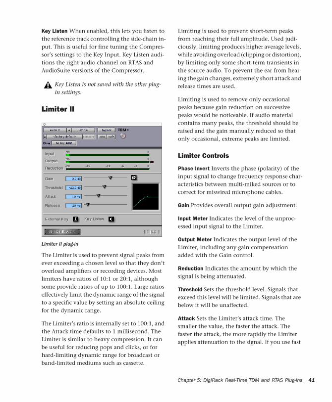
Key Listen When enabled, this lets you listen to the reference track controlling the side-chain in-put. This is useful for fine tuning the Compres-sor’s settings to the Key Input. Key Listen audi-tions the right audio channel on RTAS and AudioSuite versions of the Compressor.
Limiter II
The Limiter is used to prevent signal peaks from ever exceeding a chosen level so that they don’t overload amplifiers or recording devices. Most limiters have ratios of 10:1 or 20:1, although some provide ratios of up to 100:1. Large ratios effectively limit the dynamic range of the signal to a specific value by setting an absolute ceiling for the dynamic range.
The Limiter’s ratio is internally set to 100:1, and the Attack time defaults to 1 millisecond. The Limiter is similar to heavy compression. It can be useful for reducing pops and clicks, or for hard-limiting dynamic range for broadcast or band-limited mediums such as cassette.
Key Listen is not saved with the other plug-in settings.
Limiter II plug-in
Limiting is used to prevent short-term peaks from reaching their full amplitude. Used judi-ciously, limiting produces higher average levels, while avoiding overload (clipping or distortion), by limiting only some short-term transients in the source audio. To prevent the ear from hear-ing the gain changes, extremely short attack and release times are used.
Limiting is used to remove only occasional peaks because gain reduction on successive peaks would be noticeable. If audio material contains many peaks, the threshold should be raised and the gain manually reduced so that only occasional, extreme peaks are limited.
Limiter Controls
Phase Invert Inverts the phase (polarity) of the input signal to change frequency response char-acteristics between multi-miked sources or to correct for miswired microphone cables.
Gain Provides overall output gain adjustment.
Input Meter Indicates the level of the unproc-essed input signal to the Limiter.
Output Meter Indicates the output level of the Limiter, including any gain compensation added with the Gain control.
Reduction Indicates the amount by which the signal is being attenuated.
Threshold Sets the threshold level. Signals that exceed this level will be limited. Signals that are below it will be unaffected.
Attack Sets the Limiter’s attack time. The smaller the value, the faster the attack. The faster the attack, the more rapidly the Limiter applies attenuation to the signal. If you use fast
Chapter 5: DigiRack Real-Time TDM and RTAS Plug-Ins 41

42
attack times and heavy limiting, you should generally use a proportionally longer release time, particularly with material that contains many peaks in close proximity.
Release Controls how long it takes for the Lim-iter to be fully deactivated after the input signal drops below the threshold level. In general, if you use heavy limiting, you should use propor-tionally longer release times in order to avoid pumping that may occur when the Limiter is forced to jump back and forth between limited and unlimited signal levels. Lengthening the re-lease time will help smooth these changes in level by introducing a lag in the ramp-up/down time of attenuation. Use shorter release times on material with fewer peaks that do not occur in close proximity to each other.
Graph Displays the response curve set by the Limiter’s Threshold setting. As you adjust these controls, refer to the graph to see how the shape of this curve changes.
LFE Enable Enables plug-in processing of the LFE (low frequency effects) channel on a multi-channel track formatted for 5.1, 6.1, or 7.1 sur-round formats on some plug-ins. To disable LFE processing, deselect this button. For more infor-mation on the LFE channel, refer to the Pro Tools Reference Guide.
External Key Enables and disables side-chain processing. Side-chain processing uses the vary-ing amplitude of a separate reference track to trigger limiting. See “Using a Key Input for Side-Chain Processing” on page 15.
DigiRack Plug-Ins Guide
Key Listen When enabled, this lets you listen to the reference track controlling the side-chain in-put. This is often useful for fine tuning the Lim-iter’s settings to the Key Input. Key Listen audi-tions the right audio channel on RTAS and AudioSuite versions of the Limiter.
Gate II
The Gate (also known as a noise gate) lets a sig-nal above the selected threshold pass through to the output at unity gain, without dynamic pro-cessing. Once the input signal falls below the threshold level, the gating shuts down the sig-nal by fully or partially attenuating the output. In this way, the desired signal is allowed to pass, but unwanted signal is not. The Gate is useful for noise removal on individual tracks, and can be used for special effects such as cutting off a re-verb tail.
Key Listen settings are not saved with other plug-in settings.
Gate II plug-in

Gate Controls
Phase Invert Inverts the phase (polarity) of the input signal to change the frequency response characteristics between multi-miked sources or to correct for miswired microphone cables.
Gating Indicates the amount of reduction in dB.
Threshold Sets the threshold level. Signals that exceed this level will pass through. Signals that are below it will be gated, depending on the set-tings of the Attack, Hold, Decay, and Range con-trols (explained below).
Attack Sets the attack time of the Gate.
Hold Specifies a duration (in seconds or millisec-onds) that the Gate will stay open after the ini-tial attack cycle. This can be used as a one-shot function to keep the Gate open for longer peri-ods of time with a single crossing of the thresh-old. It can also be used to prevent gate chatter that may occur if varying input levels near the threshold cause the Gate to open and close very rapidly.
Decay Controls how long it takes for the Gate to close after the signal falls below the threshold level.
Range Sets the depth of the Gate when closed. It has a maximum depth of –80 dB. Setting the gate to higher range levels allows more of the gated audio that falls below the threshold to peek through the gate at all times. This is useful for things such as drum leakage, where you may want to suppress the overall drum kit sound by a specific amount, while emphasizing the gated instrument such as a snare.
Graph Displays the response curve set by the Gate’s Threshold and Range settings. As you ad-just these controls, refer to the graph to see how the shape of this curve changes.
External Key Enables and disables side-chain processing. Side-chain processing uses the vary-ing amplitude of a separate reference track to trigger limiting. See “Using a Key Input for Side-Chain Processing” on page 15.
Key Listen When enabled, this lets you listen to the reference track controlling the side-chain in-put. This is often useful for fine tuning the Gate’s settings to the Key Input.
Expander/Gate II
The Expander/Gate reduces noise by decreasing the gain of signals that fall below a user-select-able threshold. Expanders are particularly useful for reducing noise or signal leakage that creeps into recorded material as its level falls, as often occurs in the case of headphone leakage.
Key Listen is not saved with the other plug-in settings.
Expander/Gate II plug-in
Chapter 5: DigiRack Real-Time TDM and RTAS Plug-Ins 43

44
Expanders can be thought of as soft noise gates since they provide a gentler way of cutting off noisy low-level signals than the typically abrupt cutoff of a gate. If you want, however, you can actually use this plug-in as a gate, simply by set-ting the Ratio to its maximum value and using short attack, decay, and release settings.
Expander/Gate Controls
Phase Invert Inverts the phase (polarity) of the input signal to change the frequency response characteristics between multi-miked sources or to correct for miswired microphone cables.
Reduction Meter Indicates the amount of signal reduction in dB.
Threshold Sets the threshold level. Signals that fall below the threshold will be reduced in gain. Signals that are above it will be unaffected. (When adjusting the Threshold slider be sure that audio material is playing through the Ex-pander/Gate to see changes reflected in the Re-duction meter.)
Ratio Sets the amount of expansion. For exam-ple, if this is set to 2:1, it will lower signals below the threshold by one half. At higher ratio levels (such as 30:1 or 40:1) the Expander/Gate func-tions like a gate by reducing lower level signals much more dramatically. As you adjust the ratio control, refer to the built-in graph to see how the shape of the expansion curve changes.
Attack Sets the Expander’s attack time. This de-termines how quickly a signal’s level is reduced once it falls below the threshold. Use this along with the Ratio setting to control how soft the Expander’s gain reduction curve is.
Hold Specifies a duration (in seconds or millisec-onds) that the Expander/Gate will stay open af-ter the initial attack cycle. This can be used as a one-shot function to keep the Expander/Gate
DigiRack Plug-Ins Guide
open for longer periods of time with a single crossing of the threshold. It can also be used to prevent gate chatter that may occur if varying input levels near the threshold cause the gate to open and close very rapidly.
Decay Controls how long it takes for the gate to close after the input signal falls below the threshold level and the hold time has passed.
Range Sets the depth of the gate when closed. It has a maximum depth of –80 dB. Setting the gate to higher range levels allows more and more of the gated audio that falls below the threshold to peek through the gate at all times.
Key HPF This is a high-pass filter that removes low frequencies in the Key Input signal. Use this to define a specific frequency range of the Key Input to trigger the Expander/Gate. A typical use for this feature is to filter a drum track used as a Key Input so that only specific high fre-quencies (such as a snare drum) will open the Gate.
Key LPF This is a low-pass filter that removes high frequencies in the Key Input signal. Use this to define a specific frequency range of the Key Input to trigger the Expander/Gate. A typi-cal use for this feature is to filter a drum track used as a Key Input so that only specific low fre-quencies (such as a kick drum or tom) trigger the Expander/Gate. The maximum value for Key LPF is Off. This lets the Key Input to pass through without limiting its high-frequency bandwidth.
Graph Displays the response curve set by the Ex-pander/Gate’s Threshold, Ratio, and Range set-tings. As you adjust these controls, refer to the graph to see how the shape of this curve changes.
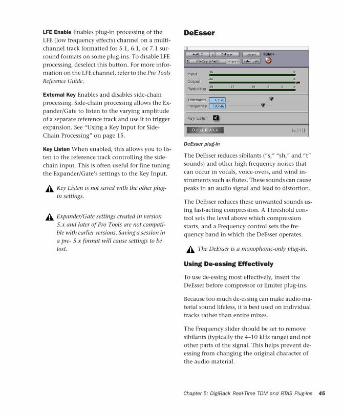
LFE Enable Enables plug-in processing of the LFE (low frequency effects) channel on a multi-channel track formatted for 5.1, 6.1, or 7.1 sur-round formats on some plug-ins. To disable LFE processing, deselect this button. For more infor-mation on the LFE channel, refer to the Pro Tools Reference Guide.
External Key Enables and disables side-chain processing. Side-chain processing allows the Ex-pander/Gate to listen to the varying amplitude of a separate reference track and use it to trigger expansion. See “Using a Key Input for Side-Chain Processing” on page 15.
Key Listen When enabled, this allows you to lis-ten to the reference track controlling the side-chain input. This is often useful for fine tuning the Expander/Gate’s settings to the Key Input.
Key Listen is not saved with the other plug-in settings.
Expander/Gate settings created in version 5.x and later of Pro Tools are not compati-ble with earlier versions. Saving a session in a pre- 5.x format will cause settings to be lost.
DeEsser
The DeEsser reduces sibilants (“s,” “sh,” and “t” sounds) and other high frequency noises that can occur in vocals, voice-overs, and wind in-struments such as flutes. These sounds can cause peaks in an audio signal and lead to distortion.
The DeEsser reduces these unwanted sounds us-ing fast-acting compression. A Threshold con-trol sets the level above which compression starts, and a Frequency control sets the fre-quency band in which the DeEsser operates.
Using De-essing Effectively
To use de-essing most effectively, insert the DeEsser before compressor or limiter plug-ins.
Because too much de-essing can make audio ma-terial sound lifeless, it is best used on individual tracks rather than entire mixes.
The Frequency slider should be set to remove sibilants (typically the 4–10 kHz range) and not other parts of the signal. This helps prevent de-essing from changing the original character of the audio material.
DeEsser plug-in
The DeEsser is a monophonic-only plug-in.
Chapter 5: DigiRack Real-Time TDM and RTAS Plug-Ins 45
46
Similarly, Threshold should be set high enough that de-essing is triggered only by sibilants. If the Threshold is set too low, a loud, non-sibilant section of audio material could cause unwanted gain reduction or cause sibilants to be over at-tenuated.
To improve de-essing of material that has both very loud and very soft passages, automate the Threshold control so that it is lower on soft sec-tions.
DeEsser Controls
Input Meter Indicates the level of the unproc-essed input signal to the DeEsser.
Output Meter Indicates the output level of the DeEsser.
Reduction Indicates the amount of gain reduc-tion in dB. It remains at 0 dB level when the in-put signal is below the threshold.
Threshold Sets the threshold level. Signals that exceed this level will be compressed. Signals that are below it will be unaffected. A setting of 0 dB is equivalent to no de-essing.
Frequency Sets the frequency band in which the DeEsser operates. Frequencies in the specified range will be gain reduced. To find the optimum Frequency setting, sweep this control back and forth during audio playback.
Key Listen Monitors the sibilant peaks used by the DeEsser as a Key Input to trigger compres-sion. This is useful for listening only to the sibi-lance and fine tuning settings to remove them.
DigiRack Plug-Ins Guide
Mod Delay and Mod Delay IIThe DigiRack Mod Delay and Mod Delay II plug-ins provide time delay-based effects such as echo, slap echo, doubling, chorusing, and flang-ing. Mod Delay II improves on Mod Delay by supporting tempo controls and sample rates up to 192 kHz.
Mod Delay(Pro Tools 5.3 and Earlier Only)
There are four different Mod Delays, each of which is capable of a different maximum delay time:
• The Short Delay provides 1024 samples of de-lay (23.2 milliseconds at 44.1 kHz or 21.3 ms at 48 kHz).
• The Slap Delay provides 7186 samples of de-lay (162 ms at 44.1 kHz or 149 ms at 48 kHz).
• The Medium Delay provides 16384 samples of delay (371 ms at 44.1 kHz kHz or 341 ms at 48 kHz).
It is recommended that you only use Mod Delay II for all new sessions. Use Mod De-lay only for compatibility with existing ses-sions. If you do not need to use Mod Delay, move it from the Plug-Ins folder into the Plug-Ins (Unused) folder. Mod Delay set-tings can be imported into Mod Delay II.

• The Long Delay provides 162474 samples of delay (3.68 seconds at 44.1 kHz or 3.38 sec-onds at 48 kHz).
Multiple Mod Delay plug-ins can be cascaded on inserts one into another to achieve even longer delay times. For each delay, set the Feedback to 0% and the Mix to 100% to get a single long de-lay (the sum of all the delay times). Adjust the various controls of each of the delays indepen-dently to create complex delay patterns.
The Mod Delays provide a Mono In/Stereo Out option. Choosing a delay in the Mono In/Stereo Out format “stereoizes” the output of a mono track. A track created in this way will then have stereo pan faders for controlling each channel of the stereo signal. As explained previously, any inserts that occur on a track after a mono-to-ste-reo insert will automatically become stereo as well.
The Long Delay TDM plug-in is only avail-able on systems equipped with HD-series or MIX-series systems.
Mod Delay plug-in (Pro Tools 5.3)
Mod Delay is not supported in sessions at sample rates greater than 48 kHz.
Mod Delay Controls
Input Controls the input volume of the delay to prevent clipping.
Mix Controls the balance between the delayed signal (wet) and the original signal (dry). If you are using a delay for flanging or chorusing, you can control the depth of the effect somewhat with the Mix setting.
LPF (Low-Pass Filter) Controls the cutoff fre-quency of the low-pass filter. Use this to attenu-ate the high frequency content of the feedback signal. The lower the setting, the more high fre-quencies are attenuated.
Delay Sets the delay time between the original signal and the delayed signal.
Depth Controls the depth of the modulation ap-plied to the delayed signal.
Rate Controls the rate of modulation of the de-layed signal.
Feedback Controls the amount of feedback ap-plied from the output of the delay back into its input. It also controls the number of repetitions of the delayed signal. Negative feedback settings give a more intense “tunnel-like” sound to flanging effects.
Automation
Mod Delay cannot have automation data copied and pasted to the adjacent left or right audio channel. This occurs even when the automation data is to or from the same control. For example, Feedback Left automation data cannot be cop-ied to Feedback Right.
The Mix control is fixed at 100% in the TDM version of the mono-to-stereo and stereo Mod Delay Long Delay on Pro Tools|HD-series systems.
Chapter 5: DigiRack Real-Time TDM and RTAS Plug-Ins 47
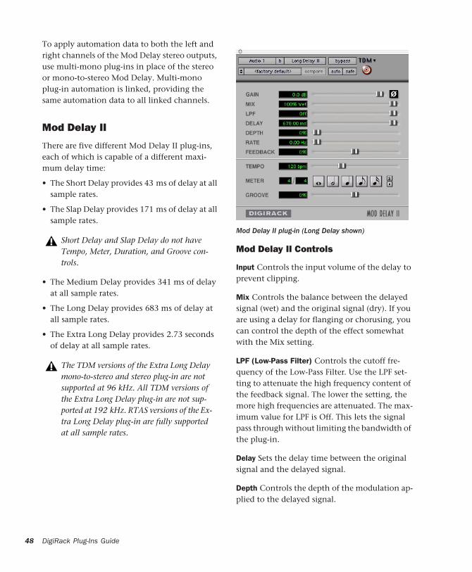
48
To apply automation data to both the left and right channels of the Mod Delay stereo outputs, use multi-mono plug-ins in place of the stereo or mono-to-stereo Mod Delay. Multi-mono plug-in automation is linked, providing the same automation data to all linked channels.
Mod Delay II
There are five different Mod Delay II plug-ins, each of which is capable of a different maxi-mum delay time:
• The Short Delay provides 43 ms of delay at all sample rates.
• The Slap Delay provides 171 ms of delay at all sample rates.
• The Medium Delay provides 341 ms of delay at all sample rates.
• The Long Delay provides 683 ms of delay at all sample rates.
• The Extra Long Delay provides 2.73 seconds of delay at all sample rates.
Short Delay and Slap Delay do not have Tempo, Meter, Duration, and Groove con-trols.
The TDM versions of the Extra Long Delay mono-to-stereo and stereo plug-in are not supported at 96 kHz. All TDM versions of the Extra Long Delay plug-in are not sup-ported at 192 kHz. RTAS versions of the Ex-tra Long Delay plug-in are fully supported at all sample rates.
DigiRack Plug-Ins Guide
Mod Delay II Controls
Input Controls the input volume of the delay to prevent clipping.
Mix Controls the balance between the delayed signal (wet) and the original signal (dry). If you are using a delay for flanging or chorusing, you can control the depth of the effect somewhat with the Mix setting.
LPF (Low-Pass Filter) Controls the cutoff fre-quency of the Low-Pass Filter. Use the LPF set-ting to attenuate the high frequency content of the feedback signal. The lower the setting, the more high frequencies are attenuated. The max-imum value for LPF is Off. This lets the signal pass through without limiting the bandwidth of the plug-in.
Delay Sets the delay time between the original signal and the delayed signal.
Depth Controls the depth of the modulation ap-plied to the delayed signal.
Mod Delay II plug-in (Long Delay shown)

Rate Controls the rate of modulation of the de-layed signal.
Feedback Controls the amount of feedback ap-plied from the output of the delay back into its input. It also controls the number of repetitions of the delayed signal. Negative feedback settings give a more intense “tunnel-like” sound to flanging effects.
Tempo Selects the desired tempo in beats per minute (bpm). This setting is independent of Pro Tools’ tempo. When a specific Duration is selected (see “Duration” below), moving this control will affect the Delay setting. Likewise, the range of both controls will be limited to the maximum available delay with the currently se-lected Duration. To enter very short or long de-lays it may be necessary to deselect all Duration buttons.
Meter Use this to enter either simple or com-pound time signatures. The Meter control de-faults to a 4/4 time signature.
Duration Specifies a desired delay from a musical perspective. Enter the desired delay by selecting appropriate note value (whole note, half note, quarter note, eight note, or sixteenth note). Se-lect the Dot or Triplet modifier buttons to dot the selected note value or make it a triplet. For
Use Edit > Identify Beat or Beat Detective to determine the tempo. For more information about Identify Beat and Beat Detective refer to the Pro Tools Reference Guide.
example, selecting a quarter note and then se-lecting the dot indicates a dotted quarter note, and selecting an eighth note and then selecting the triplet indicates a triplet eight note.
Groove Provides fine adjustment of the delay in percentages of a 1:4 subdivision of the beat. It can be used to add “swing” by slightly offsetting the delay from the precise beat of the track.
Multichannel Mod Delay II
The Tempo and Meter controls are linked on multichannel versions of Mod Delay II. Each channel has its own Duration and Groove con-trols, but the Tempo and Meter controls are glo-bal.
Tempo, Meter, Duration, and Groove controls
It is not possible to exceed the maximum delay length for a particular version of Mod Delay II. Consequently, when adjusting any of the tempo controls (Tempo, Meter, Dura-tion, and Groove) you may not be able to adjust the control across it full value range. If you encounter this behavior, switch to a version of Mod Delay II that has a longer delay time (for example, switch from Me-dium Delay to Long Delay).
Tempo, Meter, Duration, and Groove controls for a stereo instance of Mod Delay II
Dot modifierTriplet modifierDuration
Chapter 5: DigiRack Real-Time TDM and RTAS Plug-Ins 49

50
Signal GeneratorThe Signal Generator plug-in produces audio test tones in a variety of frequencies, waveforms, and amplitudes. It is particularly useful for gen-erating reference signals with which to calibrate the 96 I/O or 192 I/O and other elements of your studio. Refer to the Getting Started Guide for instructions on using Signal Generator to cali-brate the 96 I/O, or 192 I/O audio interfaces, as well as older audio interfaces.
Signal Generator Controls
Frequency Sets the frequency of the signal in hertz. Values range from a low of 20 Hz to a high of 20 kHz in a 44.1 kHz session. The upper limit of the frequency range for this setting will increase to match the Nyquist frequency (half the sample rate) in 96 kHz and 192 kHz sessions (HD-series systems only).
Level Sets the amplitude of the signal in deci-bels. Values range from a low of –95 dB to a high of 0.0 dB.
Signal Generator plug-in
The signal generator produces a tone as soon as it is inserted on a track. To mute the Signal Generator, use the Bypass button.
The pink noise generator in the Signal Gen-erator plug-in is calibrated at RMS level, rather than peak level.
DigiRack Plug-Ins Guide
Signal These buttons select the waveform. Choices are sine, square, sawtooth, triangle, white noise, and pink noise.
Pitch(TDM Systems Only)
The Pitch plug-in is designed for a variety of au-dio production applications ranging from pitch correction of musical material to sound design.
Pitch processing uses the technique of varying sample playback rate to achieve pitch transposi-tion. Because changing audio sample playback rate results in the digital equivalent of vari-speeding with tape, this is an unsatisfactory method since it changes the overall duration of the material.
The Signal Generator plug-in is not in-tended for rigorous test purposes; it is a sim-ple level calibration tool.
Pitch plug-in

Pitch transposition with the Pitch plug-in in-volves a much more complex technique: digi-tally adding or subtracting portions of the audio waveform itself, while using de-glitching cross-fades to minimize undesirable artifacts. The re-sult is a processed signal that is transposed in pitch, but still retains the same overall length as the original, unprocessed signal.
Pitch Controls
Input Level Attenuates the input level of the Pitch plug-in to help prevent internal clipping.
Signal Present Indicator LED Indicates the pres-ence of an input signal.
Clip Indicator Indicates whether clipping has oc-curred on output. It is a Clip-Hold Indicator. If clipping occurs at any time, the clip light will re-main on. To clear the Clip Indicator, click it. Long delay times and high feedback times in-crease the likelihood of clipping.
Mix Adjusts the ratio of dry signal to effected sig-nal in the output. In general, this control should be set to 100% wet, unless you are using the Pitch plug-in in-line on an Insert for an individ-ual track or element in a mix. This control can be adjusted over its entire range with little or no change in output level.
Delay Sets the delay time between the original signal and the pitch-shifted signal. It has a max-imum setting of 125 milliseconds. You can use the Delay control in conjunction with the Feed-back control to generate a single pitch-shifted echo, or a series of echoes that climb in pitch.
The Pitch plug-in was formerly called DPP-1. It is fully compatible with all set-tings and presets created for DPP-1.
Feedback Controls the amount and type of feed-back (positive or negative) applied from the out-put of the delay portion of the Pitch plug-in back into its input. It also controls the number of repetitions of the delayed signal. You can use it to produce effects that spiral up or down in pitch, with each successive echo shifted in pitch.
Coarse Adjusts the pitch of a signal in semitones over a two octave range. Pitch changes are indi-cated both in the Semitones field and in the Mu-sical Staff Relative section below this slider. Us-ing the –8va and +8va buttons in conjunction with the Coarse slider provides a full 4-octave range of adjustment.
–8va and +8va Buttons Clicking the –8va button adjusts pitch down one octave from the current setting of the coarse and fine pitch controls. Clicking the +8va button adjusts pitch up one octave from the current setting of the coarse and fine pitch controls.
Relative Pitch Entry (Musical Staff)
Clicking on any note on this musical staff se-lects a relative pitch transposition value that will be applied to an audio signal. If Middle C is illuminated, it indicates that no pitch transposi-tion has been selected. If a pitch transposition is selected, the note interval corresponding to the selected transposition value is indicated in yel-low. Alt-clicking (Windows) or Option-clicking (Macintosh) on the staff will set the coarse pitch change value to zero.
Relative pitch entry
Chapter 5: DigiRack Real-Time TDM and RTAS Plug-Ins 51

52
Fine Controls the pitch of a signal in cents (hun-dredths of a semitone) over a 100 cent range. The range of this slider is –49 to +50 cents. Pre-cise Pitch change values are indicated in the Cents field. The flat, natural, and sharp signs be-low this slider indicate deviation from the near-est semitone.
Ratio Indicates the ratio of transposition be-tween the original pitch and the selected trans-position value.
Crossfade Adjusts crossfade length in millisec-onds to optimize performance of the Pitch plug-in according to the type of audio material you are processing. The Pitch plug-in performs pitch transposition by replicating or subtracting por-tions of audio material and very quickly cross-fading between these alterations in the wave-form of the audio material.
Crossfade length affects the amount of smooth-ing performed on audio material to prevent au-dio artifacts such as clicks from occurring as the audio is looped to generate the pitch shift.
In general, small, narrow-range pitch shifts re-quire longer crossfades and large shifts require smaller ones. The disadvantage of a long cross-fade time is that it will smooth the signal, in-cluding any transients. While this is sometimes desirable for audio material such as vocals, it is not appropriate for material with sharp tran-sients such as drums or percussion.
The default setting for this control is Auto. At this setting, crossfade times are set automati-cally, according to the settings of the Coarse and Fine pitch controls. The Auto setting is appro-priate for most applications. However, you can manually adjust and optimize crossfade times using the Crossfade slider if necessary. For audio
DigiRack Plug-Ins Guide
material with sharper attack transients, use shorter crossfade times. For audio material with softer attack transients, use longer crossfade times.
Minimum Pitch Sets the minimum fundamental pitch that the Pitch plug-in will recognize when performing pitch transposition. Use this to opti-mize the Pitch plug-in’s performance by adjust-ing this control based on the lowest fundamen-tal pitch of the audio material that you want to process.
On audio material with a low fundamental pitch frequency content (such as an electric bass guitar) setting this control to a lower frequency such as 30 Hz will improve the Pitch plug-in’s performance. The most important thing to re-member when using this control is that the fun-damental frequency of audio material you want to process must be above the frequency you set here.
The range of this slider is from 15 Hz to 1000 Hz. The default setting is 60 Hz. Adjustment is tied to the current setting of the Maximum Pitch control so that the minimum range is never less than one octave, and the maximum range never more than five octaves.
Maximum Pitch Adjusts the maximum funda-mental pitch that the Pitch plug-in will recog-nize when performing pitch transposition. To optimize the Pitch plug-in’s performance, adjust this setting (and the Minimum Pitch setting) based on the highest fundamental pitch of the audio material that you want to process. The range of this slider is from 30 Hz to 4000 Hz. The default setting is 240 Hz.

TimeAdjuster(TDM Systems Only)
The TimeAdjuster plug-in provides three func-tions:
• Compensation for delays due to TDM-based routing
• Gain compensation (+/– 24 dB)
• Phase inversion for correcting out-of-phase signals
The TimeAdjuster plug-in is the most efficient way to compensate for DSP processing delays in your Pro Tools system. There are three versions of the TimeAdjuster plug-in, each of which sup-ports different sample delay ranges:
Short Supports a maximum delay of 256 sam-ples at all sample rates.
Medium Supports a maximum delay of 2048 samples at all sample rates.
Long Supports a maximum delay of 8192 sam-ples at all sample rates.
TimeAdjuster Controls
Phase Invert Inverts the phase (polarity) of the input signal. While most Digidesign plug-ins supply a phase invert button of their own, some third-party plug-ins may not. Phase inversion is
TimeAdjuster plug-in
also useful for performing delay compensation by tuning unknown delay factors by ear (see “Using TimeAdjuster for Delay Compensation” on page 54).
Gain Provides up to 24 dB of positive or negative gain adjustment. This control is useful for alter-ing the gain of a signal by a large amount in real time. For example, when you are working with audio signals that are extremely low level, you may want to adjust the channel gain to a rea-sonable working range so that a fader is posi-tioned at its optimum travel position. Use the Gain control to make a wide range of gain ad-justment in real time without having to perma-nently process the audio files, as you would with an AudioSuite plug-in.
Delay Provides up to 8192 samples of delay com-pensation adjustment, or general adjustment of phase relationships of audio recorded with mul-tiple microphones, depending on which version of TimeAdjuster is used. It defaults to a mini-mum delay of four samples, which is the delay created by use of the TimeAdjuster plug-in itself.
While phase inversion controls have been used for many years by engineers as creative tools for adjustment of frequency response between mul-tiple microphones, sample-level delay adjust-ments provide far more control. Creative use of this control can provide a powerful tool for ad-justing frequency response and timing relation-ships between audio signals recorded with mul-tiple microphones.
Chapter 5: DigiRack Real-Time TDM and RTAS Plug-Ins 53

54
Using TimeAdjuster for Delay Compensation
DSP processing in all digital systems incurs de-lay of varying amounts. You can use the Time-Adjuster TDM plug-in to apply an exact number of samples of delay to the signal path of a Pro Tools track to compensate for delay incurred by specific plug-ins. TimeAdjuster provides pre-sets for common delay-compensation scenarios.
To compensate for several plug-ins in-line, use the delay times from each settings file as refer-ences, and add them together to derive the total delay time.
Alternatively, look up the delay in samples for the plug-ins you want to compensate for, then apply the appropriate amount of delay.
To compensate for DSP-induced delays, try one of the following methods:
Phase Inversion
If you are working with phase-coherent track pairs, or tracks recorded with multiple micro-phones, you can invert the phase to negate the delay. If you don’t hear any audio when you in-vert a signal’s phase, you have precisely adjusted and compensated for the delay. This is because when you monitor duplicate signals and invert
Some plug-ins (such as Digidesign’s Maxim and DINR BNR) have different delays at different sample rates. Refer to the Digide-sign Plug-Ins Guide for more information about these plug-ins.
A delay table for DigiRack plug-ins appears in Appendix B, “DSP Delays Incurred by TDM Plug-Ins.”
DigiRack Plug-Ins Guide
the polarity (phase) of one of them, the signals will be of opposite polarity and cancel each other out. This technique is convenient for find-ing the exact delay setting for any plug-in.
To determine the delay of a plug-in by inverting its signal phase:
1 Place duplicate audio regions on two different audio tracks and pan them to the center (mono).
2 Apply the plug-in whose delay you want to calculate to the first track, and a Time Adjuster plug-in to the second track.
3 With TimeAdjuster, invert the phase.
4 Control-drag (Windows) or Command-drag (Macintosh) to fine-tune delay in one sample in-crements, or use the up/down arrow keys to change the delay one sample at a time until the audio signal disappears.
5 Change the polarity back to normal.
6 Save the TimeAdjuster setting for later use.
Comb-Filter Effect Cancellation
Adjust the delay with the signal in phase until any comb-filter effects cancel out.
Viewing Channel Delay
Because TDM plug-ins display their delay values in the Mix window’s channel delay indicators, this can be used as another method for deter-mining delay compensation.
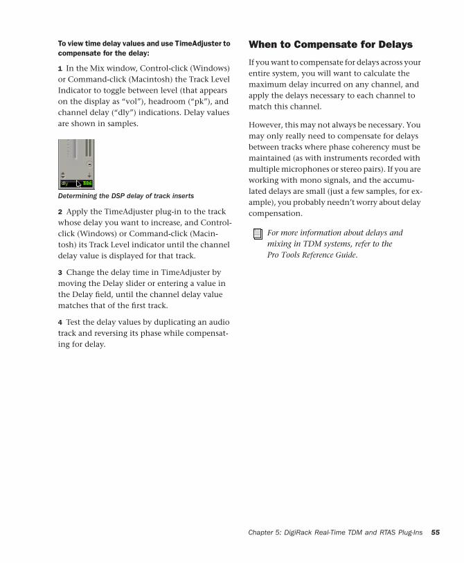
To view time delay values and use TimeAdjuster to compensate for the delay:
1 In the Mix window, Control-click (Windows) or Command-click (Macintosh) the Track Level Indicator to toggle between level (that appears on the display as “vol”), headroom (“pk”), and channel delay (“dly”) indications. Delay values are shown in samples.
2 Apply the TimeAdjuster plug-in to the track whose delay you want to increase, and Control-click (Windows) or Command-click (Macin-tosh) its Track Level indicator until the channel delay value is displayed for that track.
3 Change the delay time in TimeAdjuster by moving the Delay slider or entering a value in the Delay field, until the channel delay value matches that of the first track.
4 Test the delay values by duplicating an audio track and reversing its phase while compensat-ing for delay.
Determining the DSP delay of track inserts
When to Compensate for Delays
If you want to compensate for delays across your entire system, you will want to calculate the maximum delay incurred on any channel, and apply the delays necessary to each channel to match this channel.
However, this may not always be necessary. You may only really need to compensate for delays between tracks where phase coherency must be maintained (as with instruments recorded with multiple microphones or stereo pairs). If you are working with mono signals, and the accumu-lated delays are small (just a few samples, for ex-ample), you probably needn’t worry about delay compensation.
For more information about delays and mixing in TDM systems, refer to the Pro Tools Reference Guide.
Chapter 5: DigiRack Real-Time TDM and RTAS Plug-Ins 55
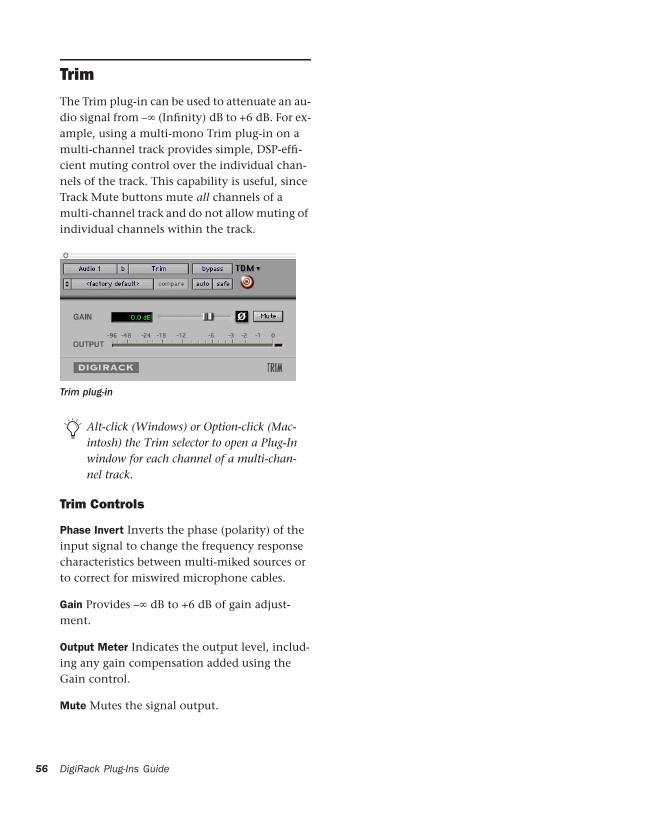
56
TrimThe Trim plug-in can be used to attenuate an au-dio signal from –∞ (Infinity) dB to +6 dB. For ex-ample, using a multi-mono Trim plug-in on a multi-channel track provides simple, DSP-effi-cient muting control over the individual chan-nels of the track. This capability is useful, since Track Mute buttons mute all channels of a multi-channel track and do not allow muting of individual channels within the track.
Trim Controls
Phase Invert Inverts the phase (polarity) of the input signal to change the frequency response characteristics between multi-miked sources or to correct for miswired microphone cables.
Gain Provides –∞ dB to +6 dB of gain adjust-ment.
Output Meter Indicates the output level, includ-ing any gain compensation added using the Gain control.
Mute Mutes the signal output.
Trim plug-in
Alt-click (Windows) or Option-click (Mac-intosh) the Trim selector to open a Plug-In window for each channel of a multi-chan-nel track.
DigiRack Plug-Ins Guide

chapter 6
DigiRack AudioSuite Plug-Ins
EQ IIThe EQ II plug-in provides a 1-Band or 4-Band EQ for adjusting the frequency spectrum of au-dio material. You can configure the 1-Band EQ as a high-pass, low-shelf, high-shelf, low-pass, or peak EQ. The 4-Band EQ provides one high-shelf, one low-shelf, and two peak EQs.
1-Band EQ II AudioSuite plug-in
The features of these plug-ins are non-real-time, but otherwise identical to their real-time coun-terparts.
4-Band EQ II AudioSuite plug-in
For information on the individual controls for these plug-ins, see “EQ II” on page 31.
Chapter 6: DigiRack AudioSuite Plug-Ins 57
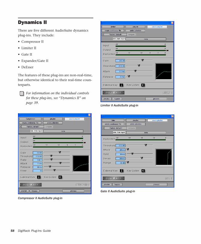
58
Dynamics IIThere are five different AudioSuite dynamics plug-ins. They include:
• Compressor II
• Limiter II
• Gate II
• Expander/Gate II
• DeEsser
The features of these plug-ins are non-real-time, but otherwise identical to their real-time coun-terparts.
For information on the individual controls for these plug-ins, see “Dynamics II” on page 39.
Compressor II AudioSuite plug-in
DigiRack Plug-Ins Guide
Limiter II AudioSuite plug-in
Gate II AudioSuite plug-in

Expander/Gate II AudioSuite plug-in
DeEsser AudioSuite plug-in
ChorusChorus adds a shimmering quality to audio ma-terial by combining a time-delayed, pitch-shifted copy of an audio signal with itself.
Gain Adjusts the input volume of the chorus to prevent clipping or increase the level of the pro-cessed signal. This slider is set to a default of +3 dB. If your source audio has been recorded very close to peak level, this +3 dB default set-ting could cause clipping. Use this control to re-duce the input level.
Selecting the Sum Input button sums the dry in-put signals (mono or stereo) before processing them. The dry signal then appears in the center of the stereo field and the wet, effected signal will be output in stereo.
When the Sum Inputs button is selected, the LFO waveform on the right channel is automat-ically phase inverted to enhance the mono-ste-reo effect.
The Chorus plug-in was formerly called D-fx Chorus. It is fully compatible with all settings and presets created for D-fx Chorus.
Chorus plug-in
Sum Inputs button
Chapter 6: DigiRack AudioSuite Plug-Ins 59

60
Mix Adjusts the balance between the effected signal and the original signal and controls the depth of the effect. Mix is adjustable from 0% to 100%.
Low-Pass Filter Controls the cutoff frequency of the Low-Pass Filter. Use this to attenuate the high frequency content of the feedback signal. The lower the setting, the more high frequen-cies are removed from the feedback signal.
The range of the Low-Pass Filter is 20 Hz to 19.86 kHz, with a maximum value of Off (which effectively means bypass).
Delay Sets the delay time between the original signal and the chorused signal. The higher the setting, the longer the delay and the wider the chorusing effect. Delay is adjustable from 0–20 milliseconds.
LFO Rate Adjusts the rate of the LFO (low fre-quency oscillator) applied to the delayed signal as modulation. The higher the setting, the more rapid the modulation. You can select either a sine wave or a triangle wave as a modulation source, using the LFO Waveform selector.
LFO Width Adjusts the intensity of the LFO ap-plied to the delayed signal as modulation. The higher the setting, the more intense the modu-lation. Use the LFO Waveform selector to select a sine or a triangle wave as a modulation source.
Feedback Controls the amount of feedback ap-plied from the output of the delayed signal back into its input. Negative settings provide a more intense effect.
LFO Waveform Selects a sine wave or triangle wave for the LFO. This affects the character of the modulation. The sine wave has a gentler ramp and peak than the triangle wave.
DigiRack Plug-Ins Guide
FlangerThe Flanger animates and adds a swirling, mov-ing quality to audio material by combing a time-delayed copy of an audio signal with itself.
The Flanger uses a through-zero flanging algo-rithm that results in a tape-like flanging effect. This technique delays the original dry signal by 256 samples, then modulates the delayed signal back and forth in time in relation to the dry sig-nal, passing through its zero point on the way.
Gain Adjusts the input volume of the flanger to prevent clipping or increase the level of the pro-cessed signal. This slider is set to a default of +3 dB. If your source audio has been recorded very close to peak level, this +3 dB default set-ting could cause clipping. Use this control to re-duce the input level.
Selecting the Sum Input button sums the dry in-put signals (mono and stereo) before processing them. The dry signal then appears in the center of the stereo field and the wet, effected signal will be output in stereo.
When the Sum Inputs button is selected, the LFO waveform on the right channel is phase in-verted to enhance the mono-stereo effect.
The Flanger plug-in was formerly called D-fx Flanger. It is fully compatible with all settings and presets created for D-fx Flanger.
Flanger plug-in

Mix Adjusts the balance between the effected signal and the original signal and controls the depth of the effect. Mix is adjustable from 0% to 100%.
High-Pass Filter Controls the cutoff frequency of the High-Pass Filter. Use this to attenuate the frequency content of the feedback signal and the frequency response of the flanging. The higher the setting, the more low frequencies are removed from the feedback signal.
LFO Rate Adjusts the rate of the LFO (low fre-quency oscillator) applied to the delayed signal as modulation. The higher the setting, the more rapid the modulation. You can select either a sine wave or a triangle wave as a modulation source, using the LFO Waveform selector.
LFO Width Adjusts the intensity of the LFO ap-plied to the delayed signal as modulation. The higher the setting, the more intense the modu-lation.
Feedback Controls the amount of feedback ap-plied from the output of the delayed signal back into its input. Negative settings provide a more intense effect.
LFO Waveform Selects a sine wave or triangle wave for the LFO. This affects the character of the modulation. The sine wave has a gentler ramp and peak than the triangle wave.
Multi-Tap DelayThe Multi-Tap Delay adds up to four indepen-dently-controllable delays or taps to the original audio signal. Use the Multi-tap delay to add spa-tialization or complex rhythmic echo effects to audio material. You can individually control the delay time and number of repetitions of each of the four taps.
Gain The Gain slider for each of the Multi-Tap delay’s four delay lines controls the input level of that individual delay tap. Adjust Gain to pre-vent clipping or increase the level of the pro-cessed signal.
The Multi-Tap Delay plug-in was formerly called D-fx Multi-Tap Delay. It is fully compatible with all settings and presets cre-ated for D-fx Multi-Tap Delay.
Multi-Tap Delay plug-in
Chapter 6: DigiRack AudioSuite Plug-Ins 61

62
Selecting the Sum Input button sums the dry in-put signals (mono or stereo) before processing them. The dry signal then appears in the center of the stereo field and the wet, effected signal will be output in stereo.
Feedback Controls the amount of feedback ap-plied from the output of the delay into its input. It also controls the number of repetitions of the delayed signal. For the feedback feature to func-tion, the Gain slider must be raised above its lowest setting.
Pan The pan sliders for each of the four taps con-trol their apparent location in the stereo field.
Delay Sets the delay time between the original signal and the delayed signal. The higher the setting, the longer the delay. This control is ad-justable from 0–1500 milliseconds (1.5 sec-onds).
Mix Adjusts the balance between the effected signal and the original signal and controls the depth of the effect. Mix is adjustable from 0% to 100%.
Selecting Audio for Processing with AudioSuite Delay
Because Multi-Tap Delay adds additional mate-rial to the end of selected audio (a delay tap), make a selection that is longer than the original source material so AudioSuite Delay can write it into the audio file.
Select only the original material, without leav-ing additional space at the end, will produce a delay that occurs after the end of the region will be cut off.
DigiRack Plug-Ins Guide
To accommodate for this, place the region in a track, and select the desired audio plus an amount of blank space at the end of the region equal to the amount of delay that you have added in the plug-in. The plug-in will then have space at the end of the region in which to write the final delay.
Ping-Pong DelayThe Ping-Pong Delay plug-in adds a controllable delay to the original audio signal. Use the Ping-Pong delay to add spatialization, and panned echo to audio material. This plug-in feeds back delayed signals to their opposite channels, cre-ating a characteristic ping-pong echo effect.
Gain Adjusts the input volume of the Ping-Pong Delay to prevent clipping or increase the level of the processed signal.
Mix Adjusts the balance between the effected signal and the original signal and controls the depth of the effect. Mix is adjustable from 0% to 100%.
The Ping-Pong Delay plug-in was formerly called D-fx Ping-Pong Delay. It is fully compatible with all settings and presets cre-ated for D-fx Ping-Pong Delay.
Ping-Pong Delay plug-in

Delay Sets the delay time between the original signal and the delayed signal. The higher the setting, the longer the delay. This control is ad-justable from 0–1500 milliseconds (1.5 sec-onds).
Low-Pass Filter Controls the cutoff frequency of the Low-Pass Filter. Use this to attenuate the high frequency content of the feedback signal. The lower the setting, the more high frequen-cies are removed from the feedback signal.
The range of the Low-Pass Filter is 20 Hz to 19.86 kHz, with a maximum value of Off (which effectively means bypass).
Feedback Controls the amount of feedback ap-plied from the output of the delay into its input. It also controls the number of repetitions of the delayed signal.
Cross-Feedback Cross-Feedback feeds the de-layed signals to their opposite channel: The left channel delay is fed to the right channel input and vice-versa. The result is a stereo echo that ping-pongs back and forth between the right and left channels.
Selecting Audio for Delay Processing
Because Ping-Pong Delay adds additional mate-rial (a delay tap) to the end of selected audio, make a selection that is longer than the original source material to allow the delay tap to be writ-ten into the end of the audio file.
Selecting only the original material, without leaving additional space at the end, will cause delay taps that occur after the end of the region to be cut off.
InvertThe Invert plug-in reverses the polarity of se-lected audio. Positive sample amplitude values are made negative, and all negative amplitudes are made positive.
This process is useful for altering the phase or polarity relationship of tracks. The Invert plug-in is useful during mixing for modifying frequency response between source tracks recorded with multiple microphones. You can also use it to correct audio recorded out of phase with an in-correctly wired cable.
Invert plug-in
Chapter 6: DigiRack AudioSuite Plug-Ins 63

64
DuplicateThe Duplicate plug-in duplicates the selected audio in place. Depending on how its controls are configured, the new region will appear in ei-ther the Regions List or playlist. You can use this to flatten or consolidate an entire track consist-ing of multiple regions into one continuous au-dio file that resides in the same place as the orig-inal individual regions.
The audio is unaffected by Pro Tools volume or pan automation, or by any real-time plug-ins that may be in use on the track as inserts. The original audio file regions are merely rewritten in place to a single duplicate file.
The Duplicate plug-in works nondestructively. You cannot choose to overwrite files.
Duplicate plug-in
DigiRack Plug-Ins Guide
DelayThe Delay plug-in provides time delay-based ef-fects, with up to 10.9 seconds of delay, at any session sample rate. You can also use it to pro-duce multiple delay-based effects, including slap echo, doubling, chorusing, and flanging.
The controls of the AudioSuite Delay plug-in op-erate in non-real-time, but are otherwise identi-cal to the real-time Mod Delay II plug-in.
If you have the Mod Delay Plug-In installed, Short Delay, Slap Delay, Medium Delay, and Long Delay will be available in the AudioSuite menu in addition to Delay (Mod Delay II). The features of these plug-ins are identical to their real-time counterparts. The only difference is that the AudioSuite versions operate in non-real time.
Delay AudioSuite plug-in
For information on the individual controls for the AudioSuite Delay plug-in, see “Mod Delay II” on page 48.
For information on the individual controls for the AudioSuite Short Delay, Slap Delay, Medium Delay, and Long Delay plug-ins, see “Mod Delay” on page 46.

Selecting Audio Delay Processing
Because AudioSuite Delay adds additional mate-rial (a delay tap) to the end of selected audio, make a selection that is longer than the original source material to allow the delay tap to be writ-ten into the end of the audio file.
Selecting only the original material, without leaving additional space at the end, will cause delay taps that occur after the end of the region to be cut off.
NormalizeThe Normalize plug-in optimizes the volume level of an audio selection. Use it on material re-corded with too little amplitude, or on material whose volume levels are inconsistent (as in a poorly recorded narration).
Unlike compression and limiting, which modify the dynamics of audio material, normalization preserves dynamics by uniformly increasing (or decreasing) amplitude.
To prevent clipping during sample rate con-version, Normalize to no greater than the range between –2 dB to –0.5 dB. Optimum settings will vary with your program mate-rial and your Conversion Quality setting (in the Editing tab of the Preferences dialog).
Normalize plug-in
Max Peak At Specifies how close to maximum level (clipping threshold) the peak level of a se-lection is boosted. Set this value by adjusting the Max Peak At slider, by entering a numeric deci-bel value below the clipping threshold, or by en-tering a percentage of the clipping threshold.
You can normalize stereo pairs together so that two sides of a stereo signal are processed relative to each other.
When multiple regions are selected across mul-tiple tracks, the Normalize plug-in can search for peaks in two different modes:
Peak On Each Chan/Track Searches for the peak level on a channel-by-channel or track-by-track basis.
Peak On All Chans/Tracks Searches for the peak level of the entire selection. If ten tracks are se-lected, for example, the Normalize function will find the peak value from all ten.
GainThe Gain plug-in boosts or lowers a selected re-gion’s amplitude by a specific amount. Use it to smooth out undesired peaks and other dynamic inconsistencies in audio material.
Gain Specifies the desired gain level. Set this value by manually adjusting the Gain slider, or by entering a numeric decibel value, or by enter-ing a percentage.
Gain plug-in
Chapter 6: DigiRack AudioSuite Plug-Ins 65

66
Find Peak When clicked, displays the peak am-plitude value of the current selection.
ReverseThe Reverse plug-in replaces the audio with a re-versed version of the selection.
Signal GeneratorThe Signal Generator plug-in produces audio test tones in a variety of frequencies, waveforms, and amplitudes.
Reverse plug-in
Signal Generator plug-in
DigiRack Plug-Ins Guide
The features of this plug-in are non-real-time, but otherwise identical to its real-time counter-part.
To create an audio region using the Signal Generator plug-in:
1 Make a selection in the Tracks window.
2 Choose AudioSuite > Signal Generator.
3 Enter values for the Frequency, Level, and Sig-nal controls.
4 Click Process in the Signal Generator plug-in.
You can use the AudioSuite Signal Genera-tor plug-in for musical purposes as well as for testing purposes. For example, you might want to add a little color to a kick drum track by doubling it with a 50 Hz tone, us-ing the kick track as the key input signal gating the tone track.
Select the Create Continuous File option for greater flexibility in making audio selec-tions for use with the Signal Generator plug-in.
For information on the individual controls for the Signal Generator plug-in, see “” on page 49.

DC Offset RemovalThe DC Offset Removal plug-in removes DC off-set from audio files. DC offset is a type of audio artifact (typically caused by miscalibrated ana-log-to-digital convertors) that can cause pops and clicks in edited material.
To check for DC offset, find a silent section in the audio material. If DC offset is present, a near-vertical fade-in with a constant or steady-state offset from zero will appear in the wave-form. Use the DC Offset Removal plug-in to re-move it.
DC Offset Removal plug-in
Time Compression/ ExpansionThe Time Compression/Expansion plug-in ad-justs the duration of selected regions, increasing or decreasing their length without changing pitch.
It is especially useful in audio post-production for adjusting audio to specific time or SMPTE durations for synchronization purposes. Time Compression/Expansion is nondestructive.
Source and Destination The Source fields display the length of the current selection before pro-cessing in each of the listed formats. All fields are always active; a change made to one value is immediately reflected in the others.
The Destination fields both display and control the final length of the selection after processing. Enter the length of the Destination file by dou-ble-clicking the appropriate field in the Destina-tion column.
Time Compression/Expansion plug-in
Normalizing a selection before using Time Compressing/Expansion may produce better results.
Chapter 6: DigiRack AudioSuite Plug-Ins 67
68
Use the Ratio, Crossfade, Min Pitch, and Accu-racy controls to fine-tune the Time Compres-sion/Expansion process.
Ratio Sets the destination length in relation to the source length. Moving the slider to the right increases the length of the destination file, while moving the slider to the left decreases its length.
Crossfade Adjusts the crossfade length in milli-seconds, optimizing performance of the Time Compression/Expansion according to the type of audio material being processed. (This plug-in achieves length modification by replicating or subtracting very small portions of audio mate-rial and very quickly crossfading between these alterations in the waveform of the audio mate-rial.)
Crossfade length affects the amount of smooth-ing performed on audio material. This prevents audio artifacts such as clicks from occurring. Long crossfade times may over-smooth a signal and its transients. This may not be desirable on drums and other material with sharp transients.
Use the Crossfade slider to manually adjust and optimize crossfade times if necessary. For audio material with sharper attack transients, use smaller crossfade times. For audio material with softer attack transients, use longer crossfade times.
Min Pitch Sets the minimum, or lowest, pitch that will be used in the plug-in’s calculations during the Time Compression/Expansion pro-cess. The control has a range of 40 Hz to 1000 Hz.
This control should be set lower when process-ing bass guitar or audio material with a low fre-quency range. Set this control higher when pro-cessing higher frequency range audio material.
DigiRack Plug-Ins Guide
Accuracy Prioritizes the processing resources al-located to audio quality (Sound) or timing (Rhythm). Moving the slider towards “Sound” generally results in better sonic quality and fewer audio artifacts. Moving the slider towards “Rhythm” puts the emphasis on keeping the tempo consistent.
When you are working with audio loops, listen carefully and adjust the Accuracy slider until you find a setting that keeps timing solid within the region. If you don’t, start and end times may be precise, but the beats in rhythmic material may appear to be shuffled if too little priority is given to Rhythm.
Time Compression & Expansion settings created in version 4.x and later of Pro Tools for Windows are not compatible with later versions.

Pitch ShiftThe Pitch Shift plug-in adjusts the pitch of any source audio file with or without a change in its duration. This is a very powerful function that transposes audio a full octave up or down in pitch with or without altering playback speed.
Gain Adjusts input level, in 10ths of a dB. Drag-ging the slider to the right increases gain, drag-ging to the left decreases gain.
Coarse and Fine Adjusts amount of pitch shift. The Coarse slider transposes in semitones (half steps). The Fine slider transposes in cents (hun-dredths of a semitone).
Time Correction Disabling this option has the ef-fect of “permanently varispeeding” your audio file. The file’s duration will be compressed or ex-tended according to the settings of the Coarse and Fine pitch controls. When Time Correction is enabled, fidelity can be affected. For example, time expansion as a result of Time Correction when lowering pitch can cause the audio to sound granulated.
Pitch Shift plug-in
Ratio Adjusts the amount of transposition (pitch change). Moving the slider to the right raises the pitch of the processed file, while mov-ing the slider to the left decreases its pitch.
Crossfade Use this to manually adjust crossfade length in milliseconds to optimize performance of the Pitch Shift plug-in according to the type of audio material you are processing. This plug-in achieves pitch transposition by processing very small portions of the selected audio mate-rial and very quickly crossfading between these alterations in the waveform of the audio mate-rial.
Crossfade length affects the amount of smooth-ing performed on audio material. This prevents audio artifacts such as clicks from occurring. In general, smaller pitch transpositions require longer crossfades; wider pitch transpositions re-quire smaller crossfades. Long crossfade times may over-smooth a signal and its transients. This is may not be desirable on drums and other material with sharp transients.
Use the Crossfade slider to adjust and optimize crossfade times. For audio material with sharper attack transients, use smaller crossfade times. For audio material with softer attack transients, use longer crossfade times.
Min Pitch Sets the lowest pitch used in the plug-in’s Pitch Shift processing. The control has a range of 40 Hz to 1000 Hz. Use it to focus the Pitch Shift process according to the audio’s spec-tral shape.
Use lower values when processing bass guitar or audio material with a low frequency range. Use higher values when processing higher frequency audio material.
Chapter 6: DigiRack AudioSuite Plug-Ins 69

70
Accuracy Prioritizes the processing resources al-located to audio quality (Sound) or timing (Rhythm). Set the slider toward Sound for better audio quality and fewer audio artifacts. Set the slider toward Rhythm for a more consistent tempo.
Reference Pitch Activates a sine wave-based pitch generator that you can use as an audible reference when pitch-shifting audio material. This feature has the following controls:
Note Adjusts the frequency of the reference tone in semitones (half steps).
Detune Provides finer adjustment of the fre-quency of the reference tone in cents (100ths of a semitone).
Gain Adjusts the volume of the reference tone in dB.
To use the Reference Pitch:
1 Select the audio material you want to use as a pitch reference. Click the preview button to be-gin playback of the selected audio.
2 Click the Reference Pitch button to activate the reference sine wave tone.
3 Adjust the Note and Detune settings to match the reference tone to the pitch of the audio play-back. Adjust the Gain setting to change the rel-ative volume of the reference tone. It may also be helpful to toggle the Reference Pitch on and off to compare pitch.
4 Select the audio material to be pitch shifted.
5 Adjust the Coarse and Fine Pitch Shift con-trols to match the pitch of the audio playback to the reference pitch.
6 Click Process to apply pitch shift to the selec-tion.
DigiRack Plug-Ins Guide

chapter 7
Using Digi ReWire (Pro Tools 6.1 Only)
Pro Tools supports ReWire version 2.0 technol-ogy developed by Propellerheads Software. Re-Wire is available as a DigiRack RTAS plug-in for Pro Tools TDM and LE systems on Windows XP and Mac OS X.
ReWire provides real-time audio and MIDI streaming between applications, with sample-accurate synchronization and common trans-port functionality.
Using ReWire, Pro Tools can send MIDI to a Re-Wire client application, such as software synthe-sizer and receive audio back from the ReWire cli-ent.
Compatible ReWire client applications are auto-matically detected by Pro Tools and are avail-able in the RTAS Plug-Ins Insert menus in Pro Tools. Selecting a ReWire client application
ReWire RTAS plug-in
Pro Tools does not support receiving MIDI from ReWire client applications.
within Pro Tools will automatically launch that application (if the client application supports this feature). Any corresponding MIDI nodes for that application will be available in the MIDI Track Output selector.
Once the outputs of your software synthesizers and samplers are routed to Pro Tools, you can:
• Process incoming audio signals with plug-ins
• Automate volume, pan, and plug-in controls
• Bounce To Disk
• Take advantage of the audio outputs of your Digidesign audio interfaces
Exchange of additional metadata such as controller and note names between Pro Tools and ReWire clients is not sup-ported.
Chapter 7: Using Digi ReWire (Pro Tools 6.1 Only) 71

72
ReWire RequirementsTo use the ReWire plug-in, you will need:
• A Digidesign-qualified Windows or Macin-tosh computer running Pro Tools TDM or Pro Tools LE software version 6.1 or higher.
• ReWire-compatible client software, such as:
• Reason from Propellerheads Software
• Live from Ableton
ReWire support is also under development for other third-party companies. For availability, check with the manufacturer or the Digidesign Web site (www.digidesign.com).
ReWire and Track Count on TDM Systems
On TDM systems, the ReWire RTAS plug-in must be inserted on an audio track. Each chan-nel of audio transmitted through ReWire then uses the same amount of resources as the audio track on which it is inserted.
Consequently, you can only use a total combi-nation of audio tracks and ReWire audio streams that does not exceed the maximum number of possible voices for your system. For example, if you are playing 40 audio tracks in a 48 kHz/24-bit session on a 128-voice Pro Tools|HD 2 core system, that will leave 88 channels of audio (88 mono, or 44 stereo) that can be used with Re-Wire. (ReWire supports a maximum of 64 audio streams per application.)
Client software must support the same sample rate as the session using ReWire. For example, third-party client software that does not support sample rates beyond 48 kHz cannot be used in 96 kHz Pro Tools sessions.
DigiRack Plug-Ins Guide
Using ReWire at higher sample rates will in-crease the load on the CPU. For example, CPU load at 96 kHz is double the load at 48 kHz. You can monitor Pro Tools CPU usage in the System Usage window, making sure to not overtax your system.
ReWire and Track Count on Pro Tools LE Systems
On Pro Tools LE-based systems, performance is determined by several factors, including host CPU speed, available memory, and buffer set-tings. Digidesign cannot guarantee 64 simulta-neous audio channel outputs with ReWire on all computer configurations.
For the latest information on recommended CPUs and system configurations, check the Digidesign Web site (www.digidesign.com/com-pato).
Using ReWireThe ReWire plug-in is installed when you install Pro Tools. All inter-application communica-tions between Pro Tools and ReWire client soft-ware is handled automatically.
To use a ReWire client application with Pro Tools:
1 Make sure that the ReWire client application is installed properly and that you have restarted your computer.
2 In Pro Tools, choose File > New Track and specify one audio track (TDM systems) or one Auxiliary Input track (LE systems), then click Create.
The standard Hardware Buffer size of 512 samples is strongly recommended for using ReWire in sessions with sample rates above 48 kHz on Pro Tools|HD systems.

3 Choose File > New Track and specify one MIDI track, then click Create.
4 In the Mix window, click the Insert Selector on the audio or Auxiliary Input track and assign the ReWire RTAS client plug-in to the track insert.
The ReWire client application will launch auto-matically in the background (if the client appli-cations supports auto-launch). If the client ap-plication does not support auto-launch, launch it manually.
5 Configure the ReWire client application to play the sounds you want.
6 In Pro Tools, set the output of the client appli-cation in the ReWire plug-in window.
7 In the Mix window, click the MIDI track’s De-vice/Channel Selector and select the ReWire cli-ent application. Some ReWire clients (such as Reason) may list multiple devices. If so, choose the device that you want.
8 Select MIDI > Thru and record enable the MIDI track. Play some notes on your MIDI con-troller to trigger the client application.
On TDM systems, the ReWire RTAS plug-in can only be inserted on an audio track. On LE systems, the ReWire plug-in can be in-serted on an audio track or an Auxiliary In-put.
Some ReWire client applications, such as Reason, support a single stereo output path (Reason’s remaining 62 outputs are mono only). If you want to use multiple stereo outputs with Reason you will need to insert multiple multi-mono ReWire plug-ins, then unlink and assign left and right outputs separately using the Link Enable and Chan-nel Selector buttons in the Plug-In window.
9 If your ReWire client application is a se-quencer and you want to begin synchronized playback with Pro Tools, press the Spacebar or click the Play button on the Pro Tools Transport.
Quitting ReWire Client Applications
When quitting Pro Tools sessions that integrate ReWire client applications, quit the client appli-cation first, then quit Pro Tools.
Tempo and Meter ChangesPro Tools transmits both Tempo and Meter data to ReWire client applications, allowing ReWire-compatible sequencers to follow any tempo and meter changes in a Pro Tools session.
With the Pro Tools Conductor button selected, Pro Tools always acts as the Tempo master, us-ing the tempo map defined in its Tempo Ruler.
If you experience system performance prob-lems while using Pro Tools with ReWire cli-ent applications, you may need to increase the Pro Tools CPU Usage Limit. See “CPU Usage Limit” on page 7 for instructions.
If you quit Pro Tools before quitting ReWire client applications, a warning dialog box may appear stating that “one or more Re-Wire applications did not terminate.” To avoid this, quit all ReWire client applica-tions before quitting Pro Tools.
Chapter 7: Using Digi ReWire (Pro Tools 6.1 Only) 73

74
With the Pro Tools Conductor button dese-lected, the ReWire client acts as the Tempo mas-ter. In both cases, playback can be started or stopped in either application.
Looping PlaybackBecause Pro Tools does not offer separate loop markers as found in other third party applica-tions such as Reason, if you want to loop play-back, do one of the following:
To loop playback in Pro Tools:
1 In the Pro Tools Time Line, select the time range that you want to loop.
2 Begin playback by pressing the Spacebar or clicking the Transport’s Play button.
Pro Tools supports tempo values from 30–300 bpm. When slaved to a ReWire cli-ent application, Pro Tools playback will be restricted to this range even if the client ap-plication’s tempo is outside this range. Ad-ditionally, some ReWire client applications (such as Reason) may misinterpret Pro Tools meter changes, resulting in mis-matched locate points and other unexpected behavior. To prevent this, avoid using meter changes in Pro Tools when using Reason as a ReWire client.
DigiRack Plug-Ins Guide
To loop playback within a ReWire client sequencer
■ With playback stopped, specify the loop within the ReWire client application and begin playback.
Automating ReWireReWire supports automation for switching in-puts during playback.
To automate switching inputs during playback:
1 Set the track’s automation to write.
2 Change the input link pop-up menu manu-ally.
– or –
Draw the automation in the Edit window.
If you create a playback loop by making a selection in the Pro Tools Time Line, once playback is started, any changes made to loop or playback markers within the Re-Wire client application will deselect the Pro Tools Time Line selection and remove the loop.
For more information on drawing automa-tion, see the Pro Tools Reference Guide.
chapter 8
Using DirectConnect (Mac OS 9 Only)
DirectConnect is a Macintosh-only Pro Tools plug-in that allows up to 32 separate audio channel outputs from compatible host-based applications, such as software-based synthesiz-ers or samplers, to be independently routed, re-corded, processed and mixed within the Pro Tools environment.
Once the outputs of your software synths and samplers are routed to Pro Tools, you can:
• Assign them to busses for plug-in processing
• Automate volume, pan, and plug-in controls
• Bounce To Disk
• Take advantage of the audio outputs of your Digidesign audio interfaces
DirectConnect is only supported on Mac OS 9. It is not supported by Pro Tools 6.x on Mac OS X. For informa-tion on using host-based applications such as software synthesizers or samplers with Pro Tools 6.x on Windows XP or Mac OS X, see Chapter 7, “Using Digi Re-Wire (Pro Tools 6.1 Only).”
If you have downloaded DirectConnect from the Digidesign Web site, see “Install-ing DirectConnect” on page 77 for installa-tion instructions.
DirectConnect RequirementsTo use DirectConnect, you will need:
• A Pro Tools HD-series or MIX-series system, or Pro Tools LE software running on a Digide-sign-approved Pro Tools configuration
• Digidesign Soft SampleCell or Third-party cli-ent software compatible with DirectConnect, such as:
• Studio9000 from Koblo
• Retro AS-1, Unity DS-1, Voodoo, or Phrazer from Bitheadz
• Absynth, B-4, Battery, Dynamo, FM7, or Reaktor from Native Instruments
• Spark XL from TC|Works
• Alkali from Audio Genetics
DirectConnect support is also under develop-ment for other third-party companies. For avail-ability, check with the manufacturer or the Digidesign Web site (www.digidesign.com).
Third-party client software must support and be configured for the same sample rate as the session to use with DirectConnect. For example, third-party client software that does not support sample rates beyond 48 kHz cannot be used in 96 kHz Pro Tools sessions.
Chapter 8: Using DirectConnect (Mac OS 9 Only) 75
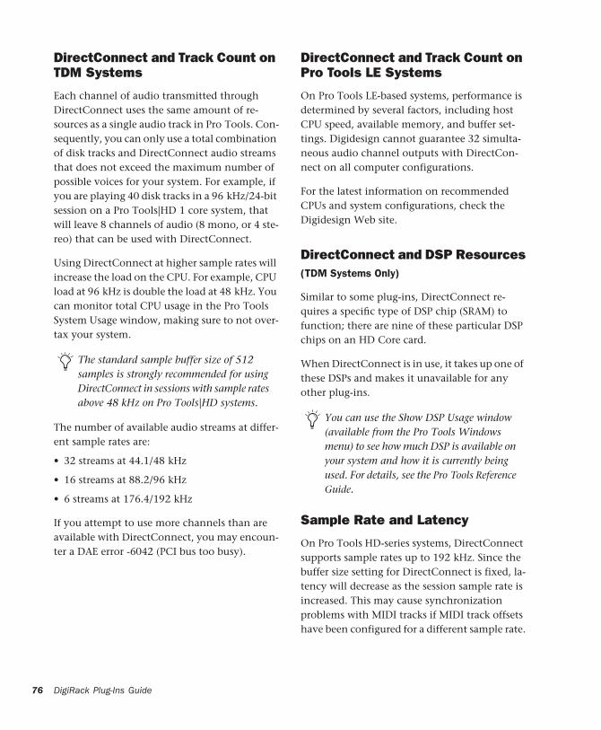
76
DirectConnect and Track Count on TDM Systems
Each channel of audio transmitted through DirectConnect uses the same amount of re-sources as a single audio track in Pro Tools. Con-sequently, you can only use a total combination of disk tracks and DirectConnect audio streams that does not exceed the maximum number of possible voices for your system. For example, if you are playing 40 disk tracks in a 96 kHz/24-bit session on a Pro Tools|HD 1 core system, that will leave 8 channels of audio (8 mono, or 4 ste-reo) that can be used with DirectConnect.
Using DirectConnect at higher sample rates will increase the load on the CPU. For example, CPU load at 96 kHz is double the load at 48 kHz. You can monitor total CPU usage in the Pro Tools System Usage window, making sure to not over-tax your system.
The number of available audio streams at differ-ent sample rates are:
• 32 streams at 44.1/48 kHz
• 16 streams at 88.2/96 kHz
• 6 streams at 176.4/192 kHz
If you attempt to use more channels than are available with DirectConnect, you may encoun-ter a DAE error -6042 (PCI bus too busy).
The standard sample buffer size of 512 samples is strongly recommended for using DirectConnect in sessions with sample rates above 48 kHz on Pro Tools|HD systems.
DigiRack Plug-Ins Guide
DirectConnect and Track Count on Pro Tools LE Systems
On Pro Tools LE-based systems, performance is determined by several factors, including host CPU speed, available memory, and buffer set-tings. Digidesign cannot guarantee 32 simulta-neous audio channel outputs with DirectCon-nect on all computer configurations.
For the latest information on recommended CPUs and system configurations, check the Digidesign Web site.
DirectConnect and DSP Resources(TDM Systems Only)
Similar to some plug-ins, DirectConnect re-quires a specific type of DSP chip (SRAM) to function; there are nine of these particular DSP chips on an HD Core card.
When DirectConnect is in use, it takes up one of these DSPs and makes it unavailable for any other plug-ins.
Sample Rate and Latency
On Pro Tools HD-series systems, DirectConnect supports sample rates up to 192 kHz. Since the buffer size setting for DirectConnect is fixed, la-tency will decrease as the session sample rate is increased. This may cause synchronization problems with MIDI tracks if MIDI track offsets have been configured for a different sample rate.
You can use the Show DSP Usage window (available from the Pro Tools Windows menu) to see how much DSP is available on your system and how it is currently being used. For details, see the Pro Tools Reference Guide.

DirectConnect and Other DAE ApplicationsDirectConnect will work with DAE-compatible applications other than Pro Tools, including se-quencers from other third-party software com-panies.
Installing DirectConnectTo use DirectConnect, you must install the plug-in description file for your software synth or sam-pler. This file must reside in the Plug-Ins folder inside the DAE Folder. Some DirectConnect cli-ent applications will do this for you during in-stallation, such as Soft SampleCell.
DirectConnect also requires the following files, that are installed automatically with the Pro Tools software:
DirectConnect This plug-in file resides in the Plug-Ins folder inside the DAE Folder (that is in the System Folder).
Digidesign StreamManager This file resides in the Extensions folder inside the System Folder.
You must have completed a full install of Pro Tools before you can use DirectConnect with third-party sequencer software.
Contact your sequencer manufacturer for information on compatibility with Direct-Connect, and DAE and DigiSystem INIT 5.3 or later.
Contact the manufacturer to obtain the plug-in description file for your DirectCon-nect-compatible software if it is not in-stalled when you install the DirectConnect client application.
Using DirectConnectSeveral DirectConnect client applications have OMS drivers, such as Soft SampleCell. Once you have installed a DirectConnect client applica-tion, be sure to create a new OMS Setup that in-cludes the DirectConnect client application’s OMS driver, or update your existing OMS Setup to include the OMS driver of the DirectConnect client application.
To update your OMS Current Studio Setup:
1 Launch the OMS Setup application.
2 Verify that your Current Studio Setup is open.
3 Choose Studio > MIDI Cards & Interfaces and follow the on-screen instructions.
4 Your DirectConnect client application’s OMS driver should appear in your Studio Setup. If not, you will need to use the OMS IAC driver (see “Configuring the IAC Driver” on page 77).
5 Choose File > Save.
6 Quit OMS Setup.
DirectConnect, OMS, and IAC
DirectConnect client applications that do not have an OMS driver, such as Studio9000 by Koblo, will require the OMS IAC Driver. Pro Tools will be able to send MIDI data to the software synth or sampler using the OMS IAC bus.
Configuring the IAC Driver
To control a software synth that does not have its own OMS driver in Pro Tools, you will need to first configure the OMS IAC driver.
Chapter 8: Using DirectConnect (Mac OS 9 Only) 77

78
To configure the OMS IAC driver:
1 If it is not already installed, install the OMS IAC driver. To do this, perform a Custom Install from the OMS Installer.
2 Once the IAC driver is installed and you have restarted your computer, you will need to up-date your OMS Studio setup. In the OMS Setup application, choose Studio > MIDI Cards and In-terfaces.
3 Once the IAC driver appears in your Studio Setup, double-click its icon and rename one of the busses as desired.
For example, if you are connecting to the Tokyo software from Koblo, rename the bus “Tokyo.”
4 Click OK.
5 Choose File > Save and then close OMS Setup.
Renaming an IAC bus
DigiRack Plug-Ins Guide
Configuring the Software Synth
Next you’ll need to route the software synthe-sizer’s audio output to DirectConnect, and as-sign its MIDI control to the IAC bus. Following is an example for configuring the Tokyo soft-ware for Koblo synths.
To configure the Tokyo application for DirectConnect:
1 Launch the Tokyo application and select the desired synth from the Synths menu.
2 Choose File > Select Drivers. Set the Audio Driver to DirectConnect and the MIDI Driver to OMS.
3 Click OK.
4 Choose Options > MIDI Setup. Set the Doc Bus to Tokyo and the Channel to 1.
5 Click OK.
The Koblo Tokyo software synth is now ready for use with Pro Tools and DirectConnect.
Drivers dialog in Tokyo application
MIDI Setup dialog in Tokyo application

Configuring Pro Tools
Configure Pro Tools to connect to your software synth through DirectConnect and OMS.
To configure Pro Tools for DirectConnect:
1 Launch Pro Tools and open a new or previ-ously saved session.
2 Choose File > New Track and specify one Aux-iliary Input (stereo) track, then click Create.
3 Choose File > New Track and specify one MIDI Track, then click Create.
4 In the Mix window, click on the new MIDI track’s Device/Channel Selector and select the DirectConnect client application (for example, Soft SampleCell) on channel 1.
5 In the Mix window, assign the DirectConnect plug-in to the Auxiliary Input track. Some Di-rectConnect client applications will launch au-tomatically in the background (such as Soft SampleCell). If your DirectConnect client appli-cation does not support this auto-launch fea-ture, open it manually.
6 Configure your DirectConnect client applica-tion to play the sounds you want. For example, if you are using Soft SampleCell, load the sam-ples, instrument, or bank you want to use.
Some third-party products provide both mono and stereo outputs, while others use mono or stereo outputs exclusively. If you cannot instance a DirectConnect plug-in on a mono track, it is likely that it can only be used on stereo tracks. Conversely, if you cannot instance a DirectConnect plug-in on a stereo track, it is likely that it can only be used on a mono track.
7 In the DirectConnect plug-in window in Pro Tools, set the output to SSC Stereo Out 1-2.
8 Select MIDI > Thru and record-enable the MIDI track. Play some notes on your MIDI con-troller to trigger Soft SampleCell.
9 Assign additional plug-ins as desired for the Auxiliary Input track.
Automating DirectConnectDirectConnect supports automation for switch-ing inputs during playback.
To automate switching inputs during playback:
1 Set the track’s automation to write.
2 Change the input link pop-up menu manu-ally.
– or –
Draw the automation in the Edit window.
DirectConnect plug-in window (Pro Tools 5.3)
For more information on drawing automa-tion, see the Pro Tools Reference Guide.
Chapter 8: Using DirectConnect (Mac OS 9 Only) 79

80
Recalling DirectConnect StatesProvided your client software supports it, Di-rectConnect lets you recall the patch settings for your software synth or sampler. Once you save and re-open your Pro Tools session, DirectCon-nect will automatically recall the settings previ-ously used. Pro Tools will even launch, if neces-sary, your client software when opening a session that uses DirectConnect.
If your client software is not running and you open a DirectConnect session, you may need to wait while Pro Tools locates and launches your client software.
DigiRack Plug-Ins Guide

appendix a
DSP Requirements for TDM Plug-Ins
The tables on the following pages show the total number of instances of each DigiRack TDM plug-in that can be powered by a single DSP chip on Pro Tools|HD-series and MIX-series cards. DSP usage differs according to card type.
There are a total of 9 DSP chips on a Pro Tools|HD card. Though there are a total of 6 DSP chips on a Pro Tools|24 MIX card, certain plug-ins, such as the Mod Delays, require a spe-cific type of DSP chip to function. The tables in-dicate the number of compatible chips per card for each plug-in.
Plug-ins used in multi-mono format on greater-than-stereo tracks require one mono instance per channel of the multi-channel audio format. A multi-mono EQ used on a 5.1 format track, for example, requires six mono instances since there are six audio channels in the 5.1 format.
Because multi-channel versions of the Compres-sor II, Limiter II, and Expander/Gate II plug-ins are available for use on greater-than-stereo tracks, separate instance counts are given for those configurations.
The tables that follow show theoretical maximum performance when no other plug-ins are sharing available DSP re-sources. You will typically use more than one type of plug-in simultaneously.
Appendix A: DSP Requirements for TDM Plug-Ins 81

82
Table 2. Maximum instances of real-time TDM plug-ins per
DigiRack Plug-Ins Guide
DSP chip for a Pro Tools HD card at different sample rates
(mono and stereo).Sample Rate: 44.1/48 kHz 88.2/96 kHz 174.6/192 kHz
Plug-In Mono Stereo Mono Stereo Mono Stereo
EQ II (1-band) 119 59 54 27 20 10
EQ II (4-band) 36 18 16 8 6 3
Compressor II 26 17 11 8 4 3
Click 3 n/a 3 n/a 1 n/a
De-esser 20 10* 9 4* 3 1*
DigiRack Pitch 1 1 1 1 1 n/a
Limiter II 26 17 11 8 4 3
Gate II 59 41 27 18 11 7
Expander/Gate II 23 20 10 9 4 3
Mod Delay I (short) 43 21 n/a n/a n/a n/a
Mod Delay I (slap) 32 16 n/a n/a n/a n/a
Mod Delay I (medium) 16 8 n/a n/a n/a n/a
Mod Delay I (long) 8 4 n/a n/a n/a n/a
Mod Delay II (short) 43 21 19 9 7 3
Mod Delay II (slap) 32 16 16 8 7 3
Mod Delay II (medium) 16 8 8 4 4 2
Mod Delay II (long) 8 4 4 2 2 1
Mod Delay II (extra long) 2 1 1 n/a n/a n/a
Dither 37 18 17 8 7 3
POW-r Dither 9 4 4 2 1 n/a
Time Adjuster (short) 91 45 41 20 15 7

* Instance counts are provided for multi-mono versions of plug-ins that have no available multichannel ver-sion.
Time Adjuster (medium) 91 45 41 20 15 7
Time Adjuster (long) 32 16 32 16 15 7
Trim 113 59* 54 27* 20 10*
Signal Generator 27 12* 11 5* 4 2*
Table 2. (Continued) Maximum instances of real-time TDM plug-ins per DSP chip for a Pro Tools HD card at different sample rates (mono and stereo).
Sample Rate: 44.1/48 kHz 88.2/96 kHz 174.6/192 kHz
Plug-In Mono Stereo Mono Stereo Mono Stereo
Appendix A: DSP Requirements for TDM Plug-Ins 83

84
Table 3. Maximum instances of real-time TDM plug-ins pe
DigiRack Plug-Ins Guide
r DSP chip for a Pro Tools HD card at 48 kHz**
Plug-In LCRQuad
& LCRS
5.0 5.1 & 6.0
6.1 & 7.0
7.1DSP chips per
HD card
EQ II (1-band) 39 29 28 19 17 14 9
EQ II (4-band) 12 9 7 6 5 4 9
Compressor II 11 9 8 6 6 6 9
De-esser* 6 5 4 3 2 2 9
DigiRack Pitch partial partial partial partial partial partial 9
Limiter II 11 9 8 6 6 6 9
Gate II 19 14 11 9 8 7 9
Expander/Gate II 15 13 12 11 11 10 9
Mod Delay I (short) 14 11 8 7 6 5 9
Mod Delay I (slap) 10 8 6 5 4 4 9
Mod Delay I (medium) 5 4 3 2 2 2 9
Mod Delay I (long) partial partial partial partial partial partial 9
Mod Delay II (short) 14 11 8 7 6 5 9
Mod Delay II (slap) 10 8 6 5 4 4 9
Mod Delay II (medium) 5 4 3 2 2 2 9
Mod Delay II (long) 2 2 1 1 1 1 9
Mod Delay II (extra long)
partial partial partial partial partial partial 9
Dither 12 9 7 6 5 4 9
POW-r Dither 3 2 1 1 2 1 9
Time Adjuster (short) 30 22 18 15 13 11 9
Time Adjuster (medium)
30 22 18 15 13 11 9

“Partial” indicates that a single instance of the multi-mono plug-in is sharing more than 1 DSP chip.
* Instance counts are provided for multi-mono versions of plug-ins that have no available multichannel ver-sion.
** Instances are roughly half at 96 kHz and a quarter at 192 kHz.
Time Adjuster (long) 10 8 6 5 4 4 9
Trim* 39 29 23 19 16 14 9
Signal Generator* 8 6 5 4 3 3 9
Table 3. (Continued) Maximum instances of real-time TDM plug-ins per DSP chip for a Pro Tools HD card at 48 kHz**
Plug-In LCRQuad
& LCRS
5.0 5.1 & 6.0
6.1 & 7.0
7.1DSP chips per
HD card
Appendix A: DSP Requirements for TDM Plug-Ins 85

86
Table 4. Maximum instances of real-time TDM plug-ins pe
DigiRack Plug-Ins Guide
r DSP chip for a Pro Tools|24 MIX card
Plug-In Mono Stereo LCRQuad
&LCRS
5.05.1&
6.0
6.1&
7.07.1
DSP chips
per Mix card
EQ II (1-band) 63 31 21 15 12 10 9 7 6
EQ II (4-band) 28 14 9 7 5 4 4 3 6
Compressor II 20 13 8 7 6 5 4 4 6
De-esser 16 8 5 4 3 2 2 2 6
DigiRack Pitch 1 1 partial partial partial partial partial partial 3
Limiter II 20 13 8 7 6 5 4 4 6
Gate II 31 21 10 7 6 5 4 3 6
Expander/Gate II
19 15 11 10 9 8 7 7 6
Mod Delay (short)
33 16 3 2 2 1 1 1 5
Mod Delay(slap)
16 8 3 2 2 1 1 1 5
Mod Delay (medium)
8 4 3 2 2 1 1 1 5
Mod Delay (long)
4 2 1 1 – – – – 5
Mod Delay (extra long)
n/a n/a n/a n/a n/a n/a n/a n/a n/a
Dither 28 14 9 7 6 4 4 3 6
POW-r Dither 8 4 2 2 1 1 1 1 6
Time Adjuster 63 31 21 15 12 10 9 7 3
Trim 63 31 21 15 12 10 9 7 6
Signal Generator 32 16 10 8 6 5 4 4 6

Table 5. Maximum instances of real-time TDM plug-ins pe
r DSP chip for a DSP Farm card“Partial” indicates that a single instance of the multi-mono plug-in is sharing more than 1 DSP chip.
Plug-In Mono Stereo LCRQuad
&LCRS
5.05.1&
6.0
6.1&
7.07.1
DSP chips per DSP
Farm card
EQ II (1-band) 25 12 8 6 5 4 3 3 4
EQ II (4-band) 10 4 3 2 1 1 1 1 4
Compressor II 8 5 3 2 2 2 1 1 4
De-esser 6 2 1 1 – – – – 4
DigiRack Pitch 1 1 partial partial partial partial partial partial 1
Limiter II 8 5 3 2 2 2 1 1 4
Gate II 16 10 5 4 3 2 2 2 4
Expander/Gate II
8 6 3 3 2 2 2 2 4
Mod Delay (short)
10 5 3 3 2 2 2 2 4
Mod Delay(slap)
5 2 1 1 1 – – – 4
Mod Delay (medium)
2 1 – – – – – – 4
Mod Delay (long)
– – – – – – – – –
Mod Delay (extra long)
n/a n/a n/a n/a n/a n/a n/a n/a n/a
Dither 12 6 4 3 2 2 1 1 4
POW-r Dither 3 1 1 0 0 0 0 0 4
Time Adjuster 23 11 9 7 5 5 4 3 4
Trim 29 15 10 7 6 5 4 3 4
Signal Generator 12 6 4 3 2 2 1 1 4
Appendix A: DSP Requirements for TDM Plug-Ins 87

88
DigiRack Plug-Ins Guide
appendix b
DSP Delays Incurred by TDM Plug-Ins
This table shows the delays inherent in each type of DigiRack TDM plug-in. Delays matter only if you use a real-time TDM plug-in on one channel of a stereo or multichannel signal but not the others. This can cause the channels to be out of phase.
Use the TimeAdjuster plug-in to compensate for these delays. See “TimeAdjuster” on page 53.
Table 3. Samples of delay incurred by each real-time DigiR
ack TDM plug-in on HD, MIX, and DSP Farm cardsPlug-InSamples of delay on HD cards
Samples of delay on MIX cards
Samples of delay on DSP Farm cards
EQ II (1-band) 4 4 4
EQ II (4-band) 4 4 4
Compressor II 4 4 4
De-esser 4 4 4
DigiRack Pitch 3 3 3
Limiter II 4 4 4
Gate II 4 4 4
Expander/Gate II 4 4 4
Mod Delay I/II (short)
4 4 4
Mod Delay I/II (slap) 4 4 4
Mod Delay I/II (medium)
4 4 4
Mod Delay I/II (long) 4 4 n/a
Appendix B: DSP Delays Incurred by TDM Plug-Ins 89

90
Mod Delay II (extra long)
4 4 n/a
Dither 4 4 4
POW-r Dither 4 4 4
Time Adjuster 4 4 4
Signal Generator 4 4 4
Table 3. (Continued)Samples of delay incurred by each real-time DigiRack TDM plug-in on HD, MIX, and DSP Farm
Plug-InSamples of delay on HD cards
Samples of delay on MIX cards
Samples of delay on DSP Farm cards
DigiRack Plug-Ins Guide

AAccuracy control 68, 70adjusting EQ 32Algorithm control 37Attack control 40, 41AudioSuite
buffer size 27EQ II 57Invert 63menu 21multichannel processing 26plug-ins 2processing 29processing preferences 27
AudioSuite plug-in selector 22AudioSuite plug-ins
Chorus 59DC Offset Removal 67Delay 64Duplicate 64Dynamics II 58EQ II 57Flanger 60Gain 65Invert 63Multi-Tap Delay 61Normalize 65Ping-Pong Delay 62Pitch Shift 69Reverse 66Signal Generator 66Time Compression/Expansion 67using 28
AudioSuite processing on networked hard drives 28
AudioSuite window 22Audition pop-up menu 25auditioning an EQ 32Auto button 12
automationAuto Latch mode 17Auto Touch mode 17creating 17plug-in 16Safe button 12
Automation Safe button 12
Bbit resolution for Dither plug-in 35, 36buffer size for AudioSuite processing 27Bypass button 25
for EQ band 32for real-time plug-ins 12
CCents control 52Chan/Track Process Mode 24Channel selector 12Chorus plug-in 59Church algorithm 38Click plug-in 33
Accented control 33Unaccented control 33
Client software 80Clip Indicator
DigiRack Pitch 51D-Verb 37
closing multiple plug-in windows 13Coarse & Fine controls 69Compare button 12Compressor II 39configuring AudioSuite Buffer 27Convert Plug-In pop-up 12Copy Settings command 18copying a plug-in setting 19CPU meter 6
index
Index 91
92
CPU power requirements for RTAS plug-ins 6CPU Usage Limit 6Create Continuous File command 24Create Individual Files command 24creating a settings subfolder 20Crossfade control 52, 68, 69Cross-Feedback control 63
DDAE error -6042 76DC Offset Removal plug-in 67Decay control 38, 43, 44DeEsser plug-in 45delay
DSP induced 7, 54, 55Delay control 51, 60, 62Delete Current Settings File command 18destination fields 67destination folder for plug-in settings 19Diffusion control 38Digidesign StreamManager file 77DirectConnect
client software 80DSP resources 76installing 77plug-in description file 77recalling states 80requirements 75track count 76
Dither bit depth for AudioSuite 27Dither plug-in 34, 35
pop-up menu 27DSP delay compensation 7, 54, 55Duplicate plug-in 64duplicating inserts 10D-Verb 37Dynamics II 58Dynamics II plug-ins 39, 58
Compressor II 39DeEsser 45Expander/Gate II 43Gate II 42Limiter II 41
DigiRack Plug-Ins Guide
EEdit Settings option 27effects
recording with 8Entire Selection mode 24EQ
adjusting 31auditioning 32high-pass 32high-shelf 31, 57low-pass 32low-shelf 31, 57peak 32
EQ II 57EQ II plug-ins 31, 57Expander/Gate II 43External Key control 40, 42Extra Long Delay plug-in 48
FFeedback control 51, 60, 61, 62File Mode Selector 24Fine control 52Flanger plug-in 60flattening a track 64Frequency control 50
GGain control 61Gain plug-in 65Gate II 42Gating control 43Graph control 42, 43
HHall algorithm 37Hardware Buffer Size 6Hi 38High-Pass Filter control 61High-Pass Filter EQ 32High-Shelf EQ 31, 32, 57Hold control 43, 44host processing 1

IIAC Driver 77Import Settings command 18importing plug-in settings 19Input Level control 62Insert Position Selector 11inserting plug-ins during playback 10inserts 8
post-disk 8pre-fader 8pre-fader operation 8
Invert plug-in 63
KKey Input
filters 15HPF control 44Key Input Selector 12LPF control 44
Key Listen control 41, 42keyboard Input for plug-in controls 14keyboard shortcuts 14Knee control 40
LLevel control 50LFE Enable button 12, 40, 42, 45LFO Rate control 60, 61LFO Waveform control 60, 61LFO Width control 60, 61Librarian menu 11Limiter II 41Link Enable buttons 12linking plug-in controls 14Lock Settings File command 18locked regions and AudioSuite processing 28Long Delay plug-in 47, 48Low Shelf EQ 32Low-Pass Filter control 39, 60Low-Pass Filter EQ 32Low-Shelf EQ 31, 57
MMaster Link button 12Max Peak At control 65
Maximum Pitch control 52Medium Delay 46, 48Minimum Pitch control 52, 68, 69Mix control 60, 62Mod Delay II plug-ins 48Mod Delay plug-ins 46
mono in/stereo out 47mono plug-ins 9moving inserts 10multi-channel plug-ins 9multi-mono plug-ins 9MultiShell II compatible plug-ins 6Multi-Tap Delay plug-in 61muted regions and AudioSuite processing 28
NNoise Shaping 34, 35, 36non-real-time plug-ins 21Normalize plug-in 65Note control 70
OOMS IAC driver 77OMS Setup application 78opening multiple plug-in windows 12output bit resolution for Dither plug-in 35Output Meter 37Overwrite File command 24
PPan control 62Paste Settings command 18pasting plug-in settings 19Peak EQ 32Peak On All Chans/Tracks mode 25Peak On All Tracks mode 65Peak On Each Chan/Track mode 25Peak On Each Track mode 65phase cancellation 54Phase Invert button 12, 32, 40, 53Ping-Pong Delay plug-in 62pink noise 50Pitch plug-in 50Pitch Shift plug-in 69
Index 93
94
Pitch transposition 51Playlist command 23plug-in controls
adjusting 14linking 14
plug-in description file 77Plug-In Selector
for AudioSuite plug-ins 22for real-time plug-ins 12
plug-in settings librarian 17, 26Plug-In window 11
closing multiple windows 13opening multiple windows 12
plug-in-induced delays 7plug-ins
as Inserts 8automating 16creating a default setting 19inserting 9inserting during playback 10mono 9moving and duplicating 10multichannel 9multi-mono 9removing 9
post-disk inserts 8POW-r Dither plug-in 35Pre-delay control 38pre-fader inserts 8previewing AudioSuite effects 25Pro Tools memory allocation 3Process Mode Selector 24processing
AudioSuite 25multichannel for AudioSuite 26preferences 27requirements of real-time plug-ins 5
QQ control 32
RRAM and Pro Tools memory 3Range control 43, 44Ratio control 40, 52, 68, 69real-time plug-ins 5recording with plug-in effects 8
DigiRack Plug-Ins Guide
Reduction meter 40, 44Reference Pitch control 70Region by Region mode 24Region List command 23Relative Pitch Entry 51Release control 40, 42Reverse plug-in 66ReWire
plug-in description file 72track count 72
Root Settings folder 18specifying 19
RTAS plug-ins 1improving performance 6
Ssaving plug-in settings 19
Save Plug-In Settings To command 18Save Settings As command 18Save Settings command 18
selecting tracks for AudioSuite processing 28Selection Reference selector 23Set As User Default command 18Set Plug-In Default To command 18Set Root Settings Folder command 18settings 11, 26
choosing a destination for 19copying 19creating subfolders 20creating User Default 19importing 19pasting 19saving 19Settings Preferences command 18
Settings menu 11Short Delay plug-in 46, 48shortcuts for keyboard input 14sibilants 45Side-Chain Input Selector 26side-chain processing 12, 15Signal control 50Signal Generator plug-in 49, 66Signal Present Indicator 51Size control 38Slap Delay plug-in 46, 48software synthesizers 78

Source and Destination controls 67subfolders, creating for settings 20System Usage window 6
TTarget button 12TC/E control 28TDM plug-ins 1, 5
DSP delay chart 89DSP requirements 81inserting on tracks 9moving and duplicating 10removing from tracks 9
Threshold control 40through-zero flanging 60Time Compression/Expansion plug-in 67Time Correction control 69Time Trimmer 28TimeAdjuster plug-in 53
using for delay compensation 7Track Selector 11Trim plug-in 56
Uunlinking plug-in controls 14Use in Playlist button 23User Default setting, creating 19
Wwhite noise 50
Index 95