Embed Size (px)
Citation preview

© Decawave 2015 This document is confidential and contains information which is proprietary to Decawave Limited. No reproduction is permitted without prior express written permission of the author
APPLICATION NOTE: APS013
APS013 APPLICATION NOTE The implementation of two-way ranging with the DW1000 Version 2.2 This document is subject to change without notice

APS013: DW1000 and two-way ranging
© Decawave 2015 This document is confidential and contains information which is proprietary to Decawave Limited. No reproduction is permitted without prior express written permission of the author
Page 2 of 15
TABLE OF CONTENTS
LIST OF TABLES ................................................................................................................................................ 2
LIST OF FIGURES ............................................................................................................................................... 2
1 INTRODUCTION ........................................................................................................................................ 3
1.1 DW1000 BASED TWR ................................................................................................................................ 3
2 IMPLEMENTATION OF RANGING .............................................................................................................. 5
2.1 DISCOVERY PHASE ........................................................................................................................................ 5 2.2 RANGING PHASE .......................................................................................................................................... 5 2.3 MESSAGES USED IN RANGING ......................................................................................................................... 6
2.3.1 General ranging frame format ........................................................................................................ 6 2.3.2 Blink frame format .......................................................................................................................... 8 2.3.3 Poll message ................................................................................................................................... 8 2.3.4 Response message .......................................................................................................................... 8 2.3.5 Final message ................................................................................................................................. 8 2.3.6 Ranging Initiation message ............................................................................................................ 9
2.4 TWR OPTIMISATION FOR POWER CONSUMPTION ............................................................................................... 9 2.4.1 Discovery phase .............................................................................................................................. 9 2.4.2 Ranging phase .............................................................................................................................. 11
3 CONCLUSION .......................................................................................................................................... 13
4 REFERENCES ........................................................................................................................................... 13
5 DOCUMENT HISTORY ............................................................................................................................. 13
6 MAJOR CHANGES ................................................................................................................................... 13
7 ABOUT DECAWAVE ................................................................................................................................ 15
LIST OF TABLES
TABLE 1: FIELDS WITHIN THE RESPONSE MESSAGE .............................................................................................................. 8 TABLE 2: FIELDS WITHIN THE FINAL MESSAGE .................................................................................................................... 9 TABLE 3: FIELDS WITHIN THE RANGING INITIATION MESSAGE ............................................................................................... 9 TABLE 4: TABLE OF REFERENCES .................................................................................................................................. 13 TABLE 5: DOCUMENT HISTORY ..................................................................................................................................... 13
LIST OF FIGURES
FIGURE 1: TWO-WAY RANGING CONCEPT ......................................................................................................................... 3 FIGURE 2: ASYMMETRIC TWR TOF FORMULA .................................................................................................................. 4 FIGURE 3: DISCOVERY AND RANGING PHASE MESSAGE EXCHANGES ....................................................................................... 5 FIGURE 4: GENERAL RANGING FRAME FORMAT .................................................................................................................. 7 FIGURE 5: RANGING MESSAGE ENCODINGS ....................................................................................................................... 8 FIGURE 6: TWR DISCOVERY PHASE TIMING PROFILE ......................................................................................................... 10 FIGURE 7: TWR RANGING PHASE TIMING PROFILE ............................................................................................................ 12
APS013: DW1000 and two-way ranging
© Decawave 2015 This document is confidential and contains information which is proprietary to Decawave Limited. No reproduction is permitted without prior express written permission of the author
Page 3 of 15
1 INTRODUCTION
In this application note two-way ranging (TWR) scheme as used by Decawave’s example application (DecaRanging) is described. TWR is a basic concept to calculate the distance between two objects by determining the time of flight (TOF) of signals travelling between them. The distance between the objects may be calculated using the formula,
𝐷𝑖𝑠𝑡𝑎𝑛𝑐𝑒 = 𝑆𝑝𝑒𝑒𝑑 𝑜𝑓 𝑟𝑎𝑑𝑖𝑜 𝑤𝑎𝑣𝑒𝑠 × 𝑇𝑂𝐹 The DW1000 uses mathematical and electronic techniques to implement a very precise clock. By recording the state of this clock when certain events occur during DW1000 transmission and reception of the radio wave signals, the DW1000 has the ability to ‘timestamp’ those events. TWR has advantages over other distance measurement and locating systems in that it can be used by stand-alone devices which only have relative distances to measure. There is no requirement for an infrastructure of fixed communicating devices to determine separation distances.
1.1 DW1000 based TWR
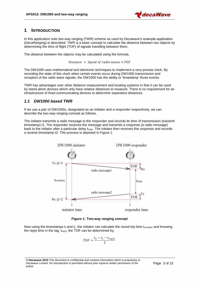
If we use a pair of DW1000s, designated as an initiator and a responder respectively, we can describe the two-way ranging concept as follows. The initiator transmits a radio message to the responder and records its time of transmission (transmit timestamp) t1. The responder receives the message and transmits a response (a radio message) back to the initiator after a particular delay treply. The initiator then receives this response and records a receive timestamp t2. This process is depicted in Figure 1.
Figure 1: Two-way ranging concept
Now using the timestamps t1 and t2, the initiator can calculate the round trip time troundtrip and knowing the reply time in the tag, treply, the TOF can be determined by,
𝑇𝑂𝐹 =𝑡2 − 𝑡1 − 𝑡𝑟𝑒𝑝𝑙𝑦
2

APS013: DW1000 and two-way ranging
© Decawave 2015 This document is confidential and contains information which is proprietary to Decawave Limited. No reproduction is permitted without prior express written permission of the author
Page 4 of 15
If we assume the speed of radio waves through air is the same as the speed of light c, then the distance between the initiator and responder can be calculated by,
𝐷𝑖𝑠𝑡𝑎𝑛𝑐𝑒 = 𝑐 ×𝑡2 − 𝑡1 − 𝑡𝑟𝑒𝑝𝑙𝑦
2
In the case of tag-to-anchor two-way ranging, there are a number of sources of error due to clock drift and frequency drift [4]. Asymmetric double sided TWR method is used in Decawave’s implementation. It reduces the error due to clock and frequency drift. Figure 2 shows a Poll-Response-Final method of doing TWR and it also shows the formula used for calculation of TOF.
Figure 2: Asymmetric TWR TOF formula
Initiator
Responder
TX
Tprop Tprop
RX
RX TXTreply1
Tround1
time
RX
TX
Treply2
Tprop
RMARKER
Tround2
Poll
Poll Resp
Resp Final
Final
The Final message communicates the initiator’s Tround and Treply times to the responder, which calculates the range to the
initiator as follows:
Tround1 × Tround2 ̶ Treply1 × Treply2
Tround1 + Tround2 + Treply1 + Treply2
Tprop =

APS013: DW1000 and two-way ranging
© Decawave 2015 This document is confidential and contains information which is proprietary to Decawave Limited. No reproduction is permitted without prior express written permission of the author
Page 5 of 15
2 IMPLEMENTATION OF RANGING
In Decawave’s two-way ranging demo, two units operate as a pair. One unit acts as a “Tag” initiating the ranging exchange and the other unit acts as an “Anchor” listening for the tag messages and performing two-way ranging exchanges with it. This is shown in Figure 3 below.
Figure 3: Discovery and Ranging phase message exchanges
2.1 Discovery phase
Initially the tag is in a discovery phase where it periodically sends a Blink message that contains its own address, and listens for a Ranging Init response from an anchor. If the tag does not get this response it sleeps for a period (default of 1 second) before blinking again. The anchor will initially listen for blinks, and when it receives a Blink message, the anchor will send a Ranging Init message to the tag, which will complete the Discovery Phase and enter the Ranging Phase.
2.2 Ranging phase
In the Ranging Phase the tag periodically performs two-way ranging exchanges with the anchor. Each two-way ranging exchange consists of the tag sending the Poll message, receiving the Response message and then sending the Final message. In the case where it is necessary for the tag to be aware of the range, the anchor may optionally send an immediate message to the tag with the calculated TOF or may wait until the next Response message to send a previous TOF. In either case, the tag can use the TOF to calculate the range. For clarity, this optional message is not shown in the remainder of this document.
Tag idles before
sending another Poll
Anchor listens
for next Poll
Unpaired Tag sends
periodic blinks, listens for a
response and sleeps
Tag sees the Ranging Init
response to pair with the
Anchor
Idle
Idle
Ranging Phase
Discovery Phase
Anchor calculates the range and
(optionally) sends a ranging report
back to the Tag either immediately
or in the next Response message
Anchor decides to pair with this Tag
for ranging and sends Ranging Init
message
Unpaired Anchor is in
listener mode listening
for Tags’ blink messages

APS013: DW1000 and two-way ranging
© Decawave 2015 This document is confidential and contains information which is proprietary to Decawave Limited. No reproduction is permitted without prior express written permission of the author
Page 6 of 15
2.3 Messages used in ranging
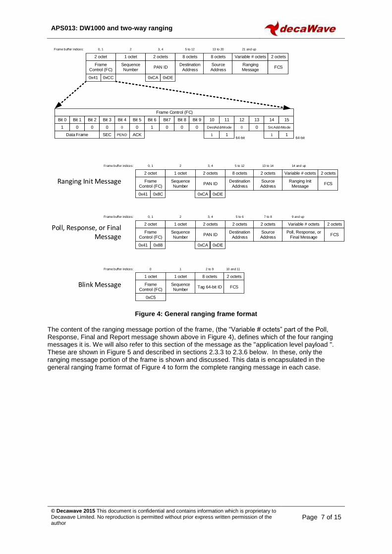
Five messages are employed: two in the Discovery Phase (the Blink and Ranging Init) and three in the Ranging Phase (the Poll, the Response, and the Final), as shown in Figure 4. Although these follow IEEE message conventions, these are not standard RTLS messages, the reader is referred to ISO/IEC 24730-62 for details of standardised message formats for use in RTLS systems based on IEEE 802.15.4-2011 UWB. The formats of the messages used in the Decawave implementation are given in the following sections.
2.3.1 General ranging frame format
The general message format, shown at the top of Figure 4, is the IEEE 802.15.4 standard encoding for a data frame. The two byte Frame Control octets vary between the messages as some use 8-octet (64-bit) addresses and others 2-octet (16-bit) addresses. A single 16-bit PAN ID (value 0xDECA) is used for all the messages. The only exception is the Blink message which is described in 2.3.2 below. In a real deployment, the PAN ID might be negotiated as part of associating with the network or it might be an installation configured constant. The blink message follows the format defined in clause 5.2.2.7 Multipurpose blink frame of the IEEE Std 802.15.4e™-2012 (Amendment to IEEE Std 802.15.4™-2011). The sequence number octet is incremented modulo-256 for every frame sent, as per IEEE rules. The source and destination addresses are either 64-bit numbers programmed uniquely into each unit (during manufacture) or 16-bit addresses temporarily assigned. The 2-octet FCS is a CRC frame check sequence following the IEEE standard, (this can be generated automatically by the DW1000 IC and appended to the transmitted message).
APS013: DW1000 and two-way ranging
© Decawave 2015 This document is confidential and contains information which is proprietary to Decawave Limited. No reproduction is permitted without prior express written permission of the author
Page 7 of 15
Figure 4: General ranging frame format
The content of the ranging message portion of the frame, (the “Variable # octets” part of the Poll, Response, Final and Report message shown above in Figure 4), defines which of the four ranging messages it is. We will also refer to this section of the message as the "application level payload ". These are shown in Figure 5 and described in sections 2.3.3 to 2.3.6 below. In these, only the ranging message portion of the frame is shown and discussed. This data is encapsulated in the general ranging frame format of Figure 4 to form the complete ranging message in each case.
Bit 0 Bit 1 Bit 2 Bit 3 Bit 4 Bit 5 Bit 6 Bit7
Frame Control (FC)
1 0 0
SEC PEND
0 1 0
Frame Control (FC)
Sequence Number
PAN ID
2 octet 1 octet 2 octets
Destination Address
8 octets
Ranging Message
Variable # octets
FCS
2 octets
Bit 8 Bit 9 10 11 12 13 14 15
0 0 0 0 SrcAddrMode
Source Address
8 octets
1 164-bit
Data Frame
0 0 DestAddrMode
1 164-bit
ACK
0x41 0xCC 0xCA 0xDE
0, 1 2 3, 4 5 to 12 13 to 20 21 and upFrame buffer indices:
Ranging Init Message Frame Control (FC)
Sequence Number
PAN ID
2 octet 1 octet 2 octets
Destination Address
8 octets
Ranging Init Message
Variable # octets
FCS
2 octets
Source Address
2 octets
0x41 0x8C 0xCA 0xDE
0, 1 2 3, 4 5 to 12 13 to 14 14 and upFrame buffer indices:
Poll, Response, or Final Message
Frame Control (FC)
Sequence Number
PAN ID
2 octet 1 octet 2 octets
Destination Address
2 octets
Poll, Response, or Final Message
Variable # octets
FCS
2 octets
Source Address
2 octets
0x41 0x88 0xCA 0xDE
0, 1 2 3, 4 5 to 6 7 to 8 9 and upFrame buffer indices:
Blink Message Frame Control (FC)
Sequence Number
1 octet 1 octet
FCS
2 octets
Tag 64-bit ID
8 octets
0xC5
0 1 2 to 9 10 and 11Frame buffer indices:

APS013: DW1000 and two-way ranging
© Decawave 2015 This document is confidential and contains information which is proprietary to Decawave Limited. No reproduction is permitted without prior express written permission of the author
Page 8 of 15
Figure 5: Ranging message encodings
2.3.2 Blink frame format
The Blink message frame format is used for sending of the tag Blink messages. The Blink frame is sent without any additional application level payload, i.e. the application data field of the blink frame is zero length. The result is a 12-octet blink frame. The encoding of this minimal blink is as shown in Figure 4.
2.3.3 Poll message
The Poll message is sent by the tag to initiate a single range measurement. For the poll message, the ranging message portion of the frame is a single octet, with the value: 0x61.
2.3.4 Response message
The Response message is sent by the anchor in response to a poll message from the tag. The Response message is 5 octets in length. Table 1 lists and describes the individual fields within the Response message.
Table 1: Fields within the Response message
Octet #’s Value Description
1 0x50 This octet value of 0x50 identifies the message as a Response
2 to 5 - This four octet field is the anchor calculated time-of-flight, representing the estimated distance between the tag and the anchor. The time units are as defined in note 1 in 2.3.5 below.
2.3.5 Final message
The Final message is sent by the tag after receiving the anchor’s response message. The Final message is 9 octets in length. Table 2 lists and describes the individual fields within the Final message.
Final Message Function
code
1 octet
Resp RX time – Poll TX
time
4 octets
Final TX time – Resp RX
time
4 octets
9Frame buffer indices: 10 to 13 14 to 17
10 to 13
Calculated
Time-of-Flight
4 octets
0x69 - -
-
Response Message Function
code
1 octet
9Frame buffer indices:
0x50
Poll Message Function
code
1 octet
9Frame buffer indices:
0x61
Ranging Init Message
Function
code
1 octet
9Frame buffer indices: 10 to 11
Tag short
address
2 octets
0x20 -
12 to 13
Response
delay
2 octets
-
APS013: DW1000 and two-way ranging
© Decawave 2015 This document is confidential and contains information which is proprietary to Decawave Limited. No reproduction is permitted without prior express written permission of the author
Page 9 of 15
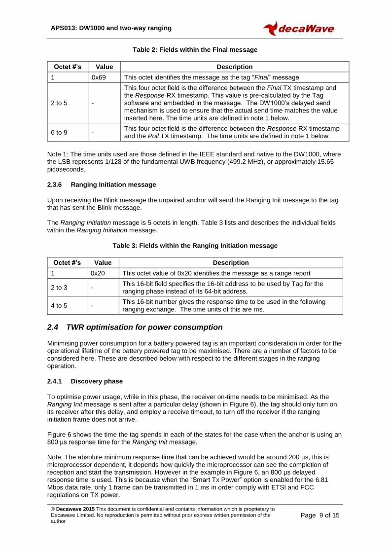
Table 2: Fields within the Final message
Octet #’s Value Description
1 0x69 This octet identifies the message as the tag “Final” message
2 to 5 -
This four octet field is the difference between the Final TX timestamp and the Response RX timestamp. This value is pre-calculated by the Tag software and embedded in the message. The DW1000’s delayed send mechanism is used to ensure that the actual send time matches the value inserted here. The time units are defined in note 1 below.
6 to 9 - This four octet field is the difference between the Response RX timestamp and the Poll TX timestamp. The time units are defined in note 1 below.
Note 1: The time units used are those defined in the IEEE standard and native to the DW1000, where the LSB represents 1/128 of the fundamental UWB frequency (499.2 MHz), or approximately 15.65 picoseconds.
2.3.6 Ranging Initiation message
Upon receiving the Blink message the unpaired anchor will send the Ranging Init message to the tag that has sent the Blink message. The Ranging Initiation message is 5 octets in length. Table 3 lists and describes the individual fields within the Ranging Initiation message.
Table 3: Fields within the Ranging Initiation message
Octet #’s Value Description
1 0x20 This octet value of 0x20 identifies the message as a range report
2 to 3 - This 16-bit field specifies the 16-bit address to be used by Tag for the ranging phase instead of its 64-bit address.
4 to 5 - This 16-bit number gives the response time to be used in the following ranging exchange. The time units of this are ms.
2.4 TWR optimisation for power consumption
Minimising power consumption for a battery powered tag is an important consideration in order for the operational lifetime of the battery powered tag to be maximised. There are a number of factors to be considered here. These are described below with respect to the different stages in the ranging operation.
2.4.1 Discovery phase
To optimise power usage, while in this phase, the receiver on-time needs to be minimised. As the Ranging Init message is sent after a particular delay (shown in Figure 6), the tag should only turn on its receiver after this delay, and employ a receive timeout, to turn off the receiver if the ranging initiation frame does not arrive. Figure 6 shows the time the tag spends in each of the states for the case when the anchor is using an 800 µs response time for the Ranging Init message. Note: The absolute minimum response time that can be achieved would be around 200 µs, this is microprocessor dependent, it depends how quickly the microprocessor can see the completion of reception and start the transmission. However in the example in Figure 6, an 800 µs delayed response time is used. This is because when the “Smart Tx Power” option is enabled for the 6.81 Mbps data rate, only 1 frame can be transmitted in 1 ms in order comply with ETSI and FCC regulations on TX power.

APS013: DW1000 and two-way ranging
© Decawave 2015 This document is confidential and contains information which is proprietary to Decawave Limited. No reproduction is permitted without prior express written permission of the author
Page 10 of 15
All times shown in Figure 6 are in microseconds (µs).
Tag
Anchor
state
TWR DISCOVERY-PHASE TIMING PROFILE
Turn on Rx
Process rx “Range init”
135
IDLE FRAME TX
600 200
IDLE RX ON
-
IDLERX ON FRAME TX
Listen for “Blink”
620
Rx preamble
135 45
Rx data
Tx preambleTx
data
Tx preambleTx
data
state
Process received “Blink”
Prepare and start “Blink” transmission
Tx preambleTx
data
-
RX ON IDLE
120
Process received
“Poll”
Rx data
16
FRAME TX
only one transmission is allowed in 1 ms when using smart tx power setting
Prepare & schedule delayed
“Range Init” frame
transmission
Blink
Range Init
Poll
135 45
45
135 45
135 45
Turn on Rx and
listen for “Poll”
START TWR EXCHANGE
Prepare & start “Poll”
transmission
6,000
DISCOVERY PHASE
Receiver timeout
TIMEOUT AND SLEEP
1201 s
DEEP SLEEP
Wake-
up
IDLE
1 s
DEEP SLEEP
OUTCOME 1
OUTCOME 2
Figure 6: TWR discovery phase timing profile
APS013: DW1000 and two-way ranging
© Decawave 2015 This document is confidential and contains information which is proprietary to Decawave Limited. No reproduction is permitted without prior express written permission of the author
Page 11 of 15
2.4.2 Ranging phase
To save power, in this phase, the tag needs to complete these operations as quickly as possible, and then return to low power mode (Sleep state). In this example, to reduce the transmission, and reception times, a preamble length of 128 is used together with shortened ranging messages (section 2.3 describes the message formats), and the highest data rate of 6.81 Mbps. As a result of using this configuration the total frame transmission time is about 180 µs, and the reception time is about 215 µs. The reception time is longer because of a 16 µs receiver start-up delay, and due to the execution time of the leading edge detection search that is part of our receive time-stamping and takes up to 60 µs after SFD detection. To reduce the time spent in the idle state, the duration of SPI transactions also need to be minimised. This is limited by the microcontroller’s SPI peripheral abilities. As DW1000 supports SPI speeds of up to 20 MHz the microcontroller should be configured to run at 20 MHz if possible (We have used an STM32 device which is limited to 18 MHz). Measures should be taken to send all the bytes of an individual SPI transaction back-to-back without any dead time between them (e.g. by employing DMA on the host processor if possible). As well as the physical speed of SPI operations the application also needs to make sure that the number of SPI read and write operations are minimised (i.e. only read / write the necessary registers for the required operation). The short response times mean that 32-bit timestamp arithmetic can be used, i.e. since 232 divided by the LSB of timestamps (128 x 499.2 MHz) is 67.2 ms. This further minimises the processor execution time and saves power. Note: The absolute minimum response time that can be achieved would be around 200 µs, this is microprocessor dependent, it depends how quickly the microprocessor can see the completion of reception and start the transmission. The anchor will respond immediately, but the tag will only send the Final 1 ms after the transmission of the Poll. This is because when the smart tx power option is enabled for a 6.81 Mbps data rate, only 1 frame can be transmitted in 1 ms to meet the ETSI / FCC regulations on transmitted power.

APS013: DW1000 and two-way ranging
© Decawave 2015 This document is confidential and contains information which is proprietary to Decawave Limited. No reproduction is permitted without prior express written permission of the author
Page 12 of 15
All times shown in Figure 7 are in microseconds (µs) unless otherwise stated.
Figure 7: TWR ranging phase timing profile
Tag
Anchor
state
TWR RANGING-PHASE TIMING PROFILE
Turn on Rx
135
IDLE FRAME TX
205 200
IDLE RX ON
-
IDLERX ON FRAME TX
Turn on Rx and
listen for “Poll”
215
Rx preamble
135 45
Rx data
Tx preambleTx
data
delayed response time = 395 us
Tx preambleTx
data
state
Process received
“Poll”
Prepare and start “Poll”
transmission
-
RX ON
Process received “Final” and
calculate ToF
IDLE
16
Prepare & schedule delayed
“Response” frame
transmission
Poll
Response
Final
135 45
Process received
“Poll”
135 45
45
135 45
Turn on Rx and
listen for “Final”
ONE TWR EXCHANGE NEXT TWR EXCHANGE
135
Tx preambleTx
data
45
Timeout and go
to sleep
IDLE SLEEP
400
Tx preambleTx
data
500,000
Wake-
up
IDLE
6,000
FRAME TX
Prepare and start “Poll”
transmission
135 45
Prepare & schedule
delayed “Final” frame
transmission
FRAME TX
Process rx “Response”
Rx data
delayed response time = 580 us
IDLE RX ON
-120

APS013: DW1000 and two-way ranging
© Decawave 2015 This document is confidential and contains information which is proprietary to Decawave Limited. No reproduction is permitted without prior express written permission of the author
Page 13 of 15
3 CONCLUSION
This application note has given an overview of two way ranging as it is implemented by Decawave in its DecaRanging application. We have also outlined optimisations that can be applied to minimise power consumption for a battery powered device.
4 REFERENCES
Reference is made to the following documents in the course of this application note: -
Table 4: Table of References
Ref Author Version Title
[1] Decawave Current DW1000 Data Sheet
[2] Decawave Current DW1000 User Manual
[3] Decawave Current APS003 Real Time Location Systems
[4] Decawave Current APS011 Sources of Error in DW1000 Based two-way ranging (TWR) Schemes
5 DOCUMENT HISTORY
Table 5: Document History
Revision Date Description
1.0 15th December 2014 Initial release
1.1 31st March 2015 Scheduled update
2.0 31st December 2015 Scheduled update
2.1 30th June 2016 Scheduled update
2.2 31st March 2017 Scheduled update
6 MAJOR CHANGES
Revision 1.0
Page Change Description
All Initial release
Revision 1.1
Page Change Description
All Change Copyright notice to 2015
1 Change revision number to 1.1
11 Fix incorrect reference
13 Add 1.1 to revision table
Add this table
14 Add new page

APS013: DW1000 and two-way ranging
© Decawave 2015 This document is confidential and contains information which is proprietary to Decawave Limited. No reproduction is permitted without prior express written permission of the author
Page 14 of 15
Revision 2.0
Page Change Description
All Updated references and page numbers
1 Change revision number to 2.0
All
Updated the text to refer to the asymmetric TWR method and related message formats and timings
Update all diagrams to use the asymmetric TWR method.
Revision 2.1
Page Change Description
All Updated references and page numbers
All Typographical corrections
1 Change revision number to 2.1
7 Repaired “Reference not found” error
Revision 2.2
Page Change Description
All Updated references and page numbers
All Typographical corrections
1 Change revision number to 2.2
5 Modification to figure 3 to show optional response
5 Modification to explanatory text
13 Addition of v2.2 to revision history table
14 Addition of this table
APS013: DW1000 and two-way ranging
© Decawave 2015 This document is confidential and contains information which is proprietary to Decawave Limited. No reproduction is permitted without prior express written permission of the author
Page 15 of 15
7 ABOUT DECAWAVE
Decawave is a pioneering fabless semiconductor company whose flagship product, the DW1000, is a complete, single chip CMOS Ultra-Wideband IC based on the IEEE 802.15.4-2011 UWB standard. This device is the first in a family of parts that will operate at data rates of 110 kbps, 850 kbps and 6.8 Mbps.
The resulting silicon has a wide range of standards-based applications for both Real Time Location Systems (RTLS) and Ultra Low Power Wireless Transceivers in areas as diverse as manufacturing, healthcare, lighting, security, transport, inventory & supply chain management.
For further information on this or any other Decawave product contact a sales representative as follows: -
Decawave Ltd Adelaide Chambers Peter Street Dublin D08 T6YA Ireland t: +353 1 6975030 e: [email protected] w: www.decawave.com