Embed Size (px)
Citation preview

Order code: LEDJ321
VersiLED 4 DMX Controller User Manual
0
100
80
60
40
20
R
R
1-10 11-20 21-30 31-40
1 2 3 4 AUTO
CHANNELMODE
SOUND
RUN MODE BLACKOUT
POWERDC INPUTDMX OUTPUT
1 = Ground2 = Data -3 = Data +
DC 9V-12V300mA min
STROBE
G
G
B
B
DIMMER/STROBESPEED
SPEEDMACROMIX
SOUNDSENSITIVITY
W/D
W
R G B W
M1: RGBM2: RGBDM3: RGBWM4: RGBWDM5: DRGBM6: DRGBW
0
100
80
60
40
20
0
100
80
60
40
20
0
100
80
60
40
20
30SEC
0.1SEC
1
8
7
6
5
4
3
2
VersiLED 4www.prolight.co.uk
1
2
3
VersiLED 4
ON
I O
OFF
M1 M4
M2 M5
M3 M6

www.prolight.co.uk VersiLED 4 DMX Controller User Manual 2
Safety advice
WARNINGFOR YOUR OWN SAFETY, PLEASE READ THIS USER MANUAL CAREFULLY BEFORE YOUR INITIAL START-UP!• Beforeyourinitialstart-up,pleasemakesurethatthereisnodamagecausedduringtransportation.
• Shouldtherebeanydamage,consultyourdealeranddonotusetheequipment.
• Tomaintaintheequipmentingoodworkingconditionandtoensuresafeoperation,itisnecessaryfortheusertofollowthesafetyinstructionsandwarningnoteswritteninthismanual.
• Pleasenotethatdamagescausedbyusermodificationstothisequipmentarenotsubjecttowarranty.
IMPORTANT:The manufacturer will not accept liability for any resulting damages caused by the non-observance of this manual or any unauthorised modification to the equipment.
OPERATING DETERMINATIONSIfthisequipmentisoperatedinanyotherway,thanthosedescribedinthismanual,theproductmaysufferdamageandthewarrantybecomesvoid.Incorrectoperationmayleadtodangere.g:short-circuit,burnsandelectricshocksetc.
Donotendangeryourownsafetyandthesafetyofothers!
Incorrectinstallationorusecancauseseriousdamagetopeopleand/orproperty.
CAUTION!KEEP THIS EQUIPMENT AWAY FROM RAIN, MOISTURE AND LIQUIDS
CAUTION! TAKE CARE USING THIS EQUIPMENT!HIGH VOLTAGE-RISK OF ELECTRIC SHOCK!!
• Neverletthepowercablecomeintocontactwithothercables.Handlethepowercableandallmainsvoltageconnectionswithparticularcaution!
• Neverremovewarningorinformativelabelsfromtheunit.
• Donotopentheequipmentanddonotmodifytheunit.
• Donotconnectthisequipmenttoadimmerpack.
• Donotswitchtheequipmentonandoffinshortintervals,asthiswillreducethesystem’slife.
• Onlyusetheequipmentindoors.
• Donotexposetoflammablesources,liquidsorgases.
• Alwaysdisconnectthepowerfromthemainswhenequipmentisnotinuseorbeforecleaning!Onlyhandlethepower-cablebytheplug.Neverpullouttheplugbypullingthepower-cable.
• Makesurethattheavailablemainssupplyvoltageisbetween100~240VAC,50/60Hz.
• Makesurethatthepowercableisnevercrimpedordamaged.Checktheequipmentandthepowercableperiodically.
• Iftheequipmentisdroppedordamaged,disconnectthemainspowersupplyimmediatelyandhaveaqualifiedengineerinspecttheequipmentbeforeoperatingagain.
• Iftheequipmenthasbeenexposedtodrastictemperaturefluctuation(e.g.aftertransportation),donotconnectpowerorswitchitonimmediately.Thearisingcondensationmightdamagetheequipment.Leavetheequipmentswitchedoffuntilithasreachedroomtemperature.
• Ifyourproductfailstofunctioncorrectly,stopuseimmediately.Packtheunitsecurely(preferablyintheoriginalpackingmaterial),andreturnittoyourProlightdealerforservice.
• Onlyusefusesofsametypeandrating.
• Repairs,servicingandpowerconnectionmustonlybecarriedoutbyaqualifiedtechnician.THISUNITCONTAINSNOUSERSERVICEABLEPARTS.
• Thisfixtureisforprofessionaluseonly-itisnotdesignedfororsuitableforhouseholduse.Theproductmustbeinstalledbyaqualifiedtechnicianinaccordancewithlocalterritoryregulations.Thesafetyoftheinstallationistheresponsibilityoftheinstaller.Thefixturepresentsrisksofsevereinjuryordeathduetofirehazards,electricshockandfalls.
• WARRANTY:Oneyearfromdateofpurchase.

www.prolight.co.uk VersiLED 4 DMX Controller User Manual 3
Product overview & technical specifications
TheVersiLED4fromLEDJisauniversalDMXcontrollerdesignedforcontrollingmulti-colourLEDfixtures.SuitableforusewithRGBorRGBWproductswithorwithoutdimmerchannels,thecontrollermaybeusedforLEDparcans,panelsorevenLEDstriplights.
VersiLED 4 DMX Controller
• Cancontroluptofourfixtures/groupsfromRGBthroughtoRGBW+Dimmer,eachfixturemaybesetindividually
• Masterdimmerfunction,evenforRGBWproducts
• RGBWcolourmixonfadercontrol
• LTPcontrolsystemforintuitiveoperation
• Strobefunctionwithadjustablespeed(1-20Hz)
Specifications VersiLED 4
Powersupply DC9V-12V,300mAmin(byadaptorincluded)
Dimensions 60x202x110mm
Weight 0.8kg
Ordercode LEDJ321
0
100
80
60
40
20
R
R
1-10 11-20 21-30 31-40
1 2 3 4 AUTO
CHANNELMODE
SOUND
RUN MODE BLACKOUT
POWERDC INPUTDMX OUTPUT
1 = Ground2 = Data -3 = Data +
DC 9V-12V300mA min
STROBE
G
G
B
B
DIMMER/STROBESPEED
SPEEDMACROMIX
SOUNDSENSITIVITY
W/D
W
R G B W
M1: RGBM2: RGBDM3: RGBWM4: RGBWDM5: DRGBM6: DRGBW
0
100
80
60
40
20
0
100
80
60
40
20
0
100
80
60
40
20
30SEC
0.1SEC
1
8
7
6
5
4
3
2
VersiLED 4www.prolight.co.uk
1
2
3
VersiLED 4
ON
I O
OFF
M1 M4
M2 M5
M3 M6
01-RGBW/Dchannelfaders
02-Fixture/groupbuttons&LEDindicators
03-Channelmodeselection&LEDindicators
04-Runmodeselect(autoorsound)
05-Blackoutbutton
06-Strobebutton
07-RGBWcolourmix
08-Colourmacrofader
09-Speedcontrol
10-Strobespeed/soundsensitivity/masterdimmer
11-3-PinDMXoutput
12-DCpowerinput(centre+ve)
13-Poweron/offswitch
Inthebox:1 x controller, 1 x power adaptor & 1 x user manual
01
11 12 13
02
04 05 06
03 07 08 09 10

www.prolight.co.uk VersiLED 4 DMX Controller User Manual 4
Initial setup:
ConnectthesuppliedmainspoweradaptortotheDCpowerinputonthecontrollerandthentoasuitablemainsvoltagesupply(100-240VAC~50/60Hz).
Thecontrollercanbeusedtocontrol3or4colourLEDproductseachwithorwithoutadimmerchannel.
ThecontrollerisbasedaroundLTP(LastTakesPrecedence)acrossitscontrolsurface,thismeansthelastcommandexecutedonthecontrollerwilloverridethepreviouscommand.Becauseofthis,thecontrolleriseasytouseforthosewhocarrylittleknowledgeofDMXcontrollers.
DMX channel assignment:
ThecontrollerhaspresetDMXstartaddressesforeachofthefourfixtures.PleasesetyourfixturetothefollowingDMXaddresses.Pleasenote:IftwoormorefixturesaresettothesameDMXaddresstheywillreceivethesameDMXcommands.
Master dimmer:
ThecontrolleralsohasanadditionalMasterDimmerfunction.WhileholdingdowntheBlackoutbutton,usethestrobe/dimmerfadertoadjusttheoverallmasterintensity.Thisfunctionwilloperateforallfixturesregardlessoffixtureselection.Themasterdimmerfunctionwilloverridealloutputsincludingsoundandautomodes.Ifyouhaveusedthemasterdimmertodimyourfixture(s)tozeroyouwillhavetodimthembackupinordertousemanualdimming/colourmixingagain.
01) RGBW/D channel faders:
TheRGBW/Dfadersareusedtocreateamanualcolourmix.Firstselectthefixturegroupsasrequiredfromthefourfixturegroupsandthenusethefaderstoadjustthecolourandintensityasrequired.
02) Fixture/group buttons and LED indicators:
Thefixture/groupbuttonsareusedtoselectordeselectfixtures.NexttoeachbuttonisanLEDindicator,thiswillilluminatewhenthefixturesareselected.
03) Channel mode selection and LED indicators:
Thecontrollercanbeusedtocontroluptofourfixtures/groupsfromRGBorRGBW,eachfixturemaybesetindividuallytosuittheDMXchannelsofyourLEDfixtures.Selectthedesiredfixture/groupusingthefixture/groupbuttons,thenselectthechannelmode.Unselectthefixture/groupandthenrepeattheprocessforeachofthefourfixture/groupsuntilset.Pleasenote:WhenusingMode4andMode6,thedimmerchanneloutputvaluewillbe255,thisenablesyoutocolourmixandthenusethemasterdimmerdetailedabove.
Operating instructions
Fixture Number Group DMX Start Address
1 001
2 011
3 021
4 031

www.prolight.co.uk VersiLED 4 DMX Controller User Manual 5
Fader allocation VS Mode chart:
04) Run mode select (auto or sound):
Thebuilt-incolourmacro’smaybetriggeredbyeithersoundcontrolorautowithspeedcontrol.PresstheRunModebuttontochangebetweensoundorautocontrol.TheLEDindicatorwillilluminatetoshowtheRunMode.Usethespeedandsoundsensitivityfaderstoadjusttheautospeedorsoundsensitivity.
05) Blackout button:
Theblackoutcontrolcanbeusedforinstantblackout(off)commandsofthefixturescontrolledbytheVersiLED4controller.Theblackoutbuttonisaglobalcommandandwillcontrolthefixturesregardlessofanyfixture/groupselection.
PressandholdtheblackoutbuttontoenabletheMasterDimmerfunctionandatthesametimeusethestrobespeed/dimmerfadertocontroloverallintensityofthedimmerchannels.Thiswillalsofunctionasaglobalcommandandwillcontrolthefixturesregardlessofanyfixture/groupselection.
06) Strobe button:
PressandholdtheStrobebuttontoactivateawhitestrobeacrossthefixturesselectedonthefixture/group.Whileholdingthebutton,thestrobespeedcanbeadjustedusingthestrobespeed/soundsensitivity/dimmerfader.Thestrobespeedisadjustable1Hz-20Hz.Pleasenote:Ifthemasterdimmerfunctionhasbeensettozerothenthestrobewillnotoperate.Pleasesetthemasterdimmerbackupforthestrobetofunctionagain.
07) RGBW colour mix:
TheRGBWcolourmixfadercanbeusedforrapidselectionofstaticcolours.PushthefadertofadefromRed,throughGreenandBlueuptofullonattheupperlimitofthefader.
08) Colour macro fader:
TheVersiLED4controllerhasbuiltinRGBcolourmacro’sthatcanbetriggeredbysoundwithadjustablesensitivityorautowithspeedcontrol.Selectthedesiredfixture/groupsandthenusethemacrofadertoselectfromoneoftheeightinternalcolourmacros.Theautospeedcanbesetusingthespeedfader,whilethesoundsensitivitycanbesetusingthestrobespeed/soundsensitivity/masterdimmerfader.
Operating instructions
Mode Fader 1 Fader 2 Fader 3 Fader 4 DMX Allocation
M1 RGB Red Green Blue - RGB
M2 RGBD Red Green Blue Dimmer RGB+CH4MasterDimmer
M3 RGBW Red Green Blue White RGBW
M4 RGBWD Red Green Blue White RGBW+CH5(fixedat255)
M5 DRGB Red Green Blue Dimmer Dimmer+RGB
M6 DRGBW Red Green Blue White RGBW+CH1(fixedat255)

www.prolight.co.uk VersiLED 4 DMX Controller User Manual 6
Operating instructions
09) Speed control:
Thespeedcontrolfaderisusedtoadjustthespeedofthebuiltincolourmacros.
10) Strobe speed/sound sensitivity/master dimmer:
Thestrobespeed/soundsensitivity/masterdimmerfaderprovidescontrolformultiplefunctionsonthecontroller.
11) 3-Pin DMX output:
DMXoutputconnection.3-pinXLRoutputsocket.Pin1=Ground,Pin2=data–ve,Pin3=data+ve
12) DC power input (centre +ve):
Centrepositivetypeconnection.9-12VDC,300mAminimumregulatedtype.
13) Power on/off switch:
Usethisswitchtopowerthecontrolleron/off.
Macro Channel Value Description
N/A 000-007 Blackout
1 008-038 Red/GreenFade
2 039-069 Red/BlueFade
3 070-100 Green/BlueFade
4 101-131 Red/Green/BlueFade
5 132-162 Red/GreenChange
6 163-193 Red/BlueChange
7 194-224 Green/BlueChange
8 225-255 Red/Green/BlueChange
www.prolight.co.uk VersiLED 4 DMX Controller User Manual 7
Setting the DMX address:
TheDMXmodeenablestheuseofauniversalDMXcontroller.Eachfixturerequiresa“startaddress”from1-511.Afixturerequiringoneormorechannelsforcontrolbeginstoreadthedataonthechannelindicatedbythestartaddress.Forexample,afixturethatoccupiesoruses7channelsofDMXandwasaddressedtostartonDMXchannel100,wouldreaddatafromchannels:100,101,102,103,104,105and106.Chooseastartaddresssothatthechannelsuseddonotoverlap.E.g.thenextunitinthechainstartsat107.
DMX 512:
DMX(DigitalMultiplex)isauniversalprotocolusedasaformofcommunicationbetweenintelligentfixturesandcontrollers.ADMXcontrollersendsDMXdatainstructionsformthecontrollertothefixture.DMXdataissentasserialdatathattravelsfromfixturetofixtureviatheDATA“IN”andDATA“OUT”XLRterminalslocatedonallDMXfixtures(mostcontrollersonlyhaveadata“out”terminal).
DMX linking:
DMXisalanguageallowingallmakesandmodelsofdifferentmanufacturestobelinkedtogetherandoperatefromasinglecontroller,aslongasallfixturesandthecontrollerareDMXcompliant.ToensureproperDMXdatatransmission,whenusingseveralDMXfixturestrytousetheshortestcablepathpossible.TheorderinwhichfixturesareconnectedinaDMXlinedoesnotinfluencetheDMXaddressing.Forexample;afixtureassignedtoaDMXaddressof1maybeplacedanywhereinaDMXline,atthebeginning,attheend,oranywhereinthemiddle.WhenafixtureisassignedaDMXaddressof1,theDMXcontrollerknowstosendDATAassignedtoaddress1tothatunit,nomatterwhereitislocatedintheDMXchain.
DATA cable (DMX cable) requirements (for DMX operation):
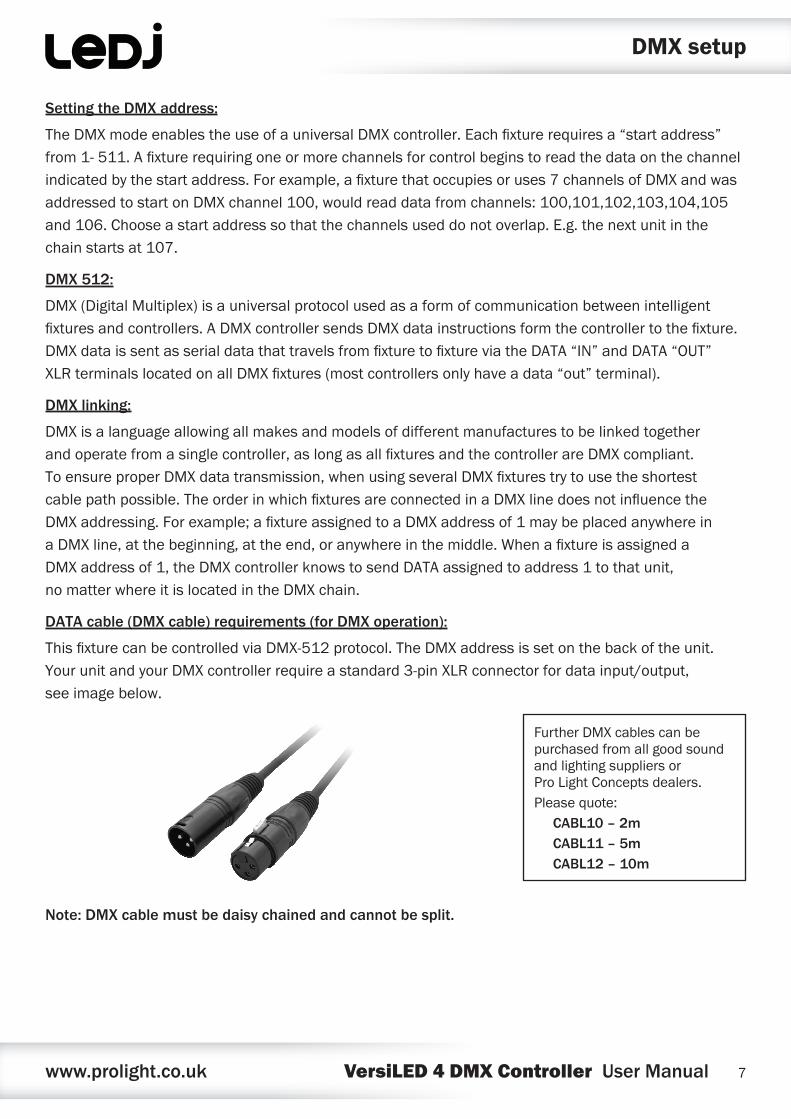
ThisfixturecanbecontrolledviaDMX-512protocol.TheDMXaddressissetonthebackoftheunit.YourunitandyourDMXcontrollerrequireastandard3-pinXLRconnectorfordatainput/output,seeimagebelow.
Note: DMX cable must be daisy chained and cannot be split.
DMX setup
FurtherDMXcablescanbepurchasedfromallgoodsoundandlightingsuppliersorProLightConceptsdealers.Pleasequote:
CABL10 – 2mCABL11 – 5mCABL12 – 10m
www.prolight.co.uk VersiLED 4 DMX Controller User Manual 8
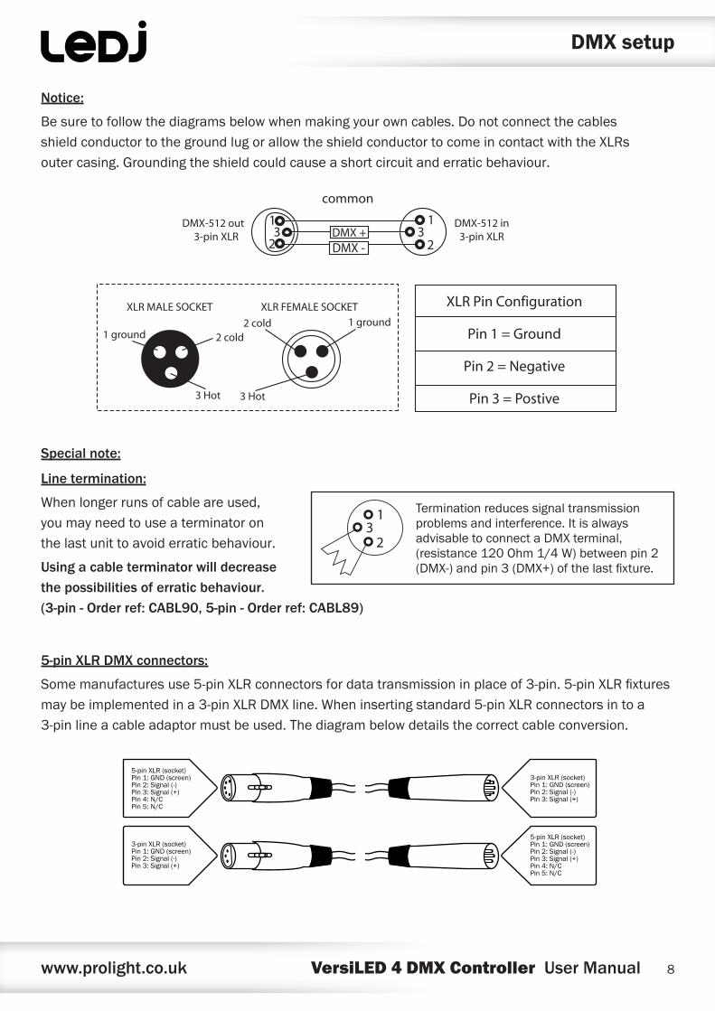
Notice:
Besuretofollowthediagramsbelowwhenmakingyourowncables.DonotconnectthecablesshieldconductortothegroundlugorallowtheshieldconductortocomeincontactwiththeXLRsoutercasing.Groundingtheshieldcouldcauseashortcircuitanderraticbehaviour.
Special note:
Line termination:
Whenlongerrunsofcableareused,youmayneedtouseaterminatoronthelastunittoavoiderraticbehaviour.
Using a cable terminator will decrease the possibilities of erratic behaviour. (3-pin - Order ref: CABL90, 5-pin - Order ref: CABL89)
5-pin XLR DMX connectors:
Somemanufacturesuse5-pinXLRconnectorsfordatatransmissioninplaceof3-pin.5-pinXLRfixturesmaybeimplementedina3-pinXLRDMXline.Wheninsertingstandard5-pinXLRconnectorsintoa3-pinlineacableadaptormustbeused.Thediagrambelowdetailsthecorrectcableconversion.
Terminationreducessignaltransmissionproblemsandinterference.ItisalwaysadvisabletoconnectaDMXterminal,(resistance120Ohm1/4W)betweenpin2(DMX-)andpin3(DMX+)ofthelastfixture.
5-pin XLR (socket)Pin 1: GND (screen)Pin 2: Signal (-)Pin 3: Signal (+)Pin 4: N/CPin 5: N/C
3-pin XLR (socket)Pin 1: GND (screen)Pin 2: Signal (-)Pin 3: Signal (+)
3-pin XLR (socket)Pin 1: GND (screen)Pin 2: Signal (-)Pin 3: Signal (+)
5-pin XLR (socket)Pin 1: GND (screen)Pin 2: Signal (-)Pin 3: Signal (+)Pin 4: N/CPin 5: N/C
DMX setup

www.prolight.co.uk VersiLED 4 DMX Controller User Manual 9
WEEE notice
Correct Disposal of this Product (Waste Electrical & Electronic Equipment)
(Applicable in the European Union and other European countries with separate collection systems)
Thismarkingshownontheproductoritsliterature,indicatesthatitshouldnotbedisposedwithotherhouseholdwastesattheendofitsworkinglife.Topreventpossibleharmtotheenvironmentorhumanhealthfromuncontrolledwastedisposal,pleaseseparatethisfromothertypesofwastesandrecycleitresponsiblytopromotethesustainablereuseofmaterialresources.
Householdusersshouldcontacteithertheretailerwheretheypurchasedthisproduct,ortheirlocalgovernmentoffice,fordetailsofwhereandhowtheycantakethisitemforenvironmentallysaferecycling.
Businessusersshouldcontacttheirsupplierandcheckthetermsandconditionsofthepurchasecontract.Thisproductshouldnotbemixedwithothercommercialwastesfordisposal.

www.prolight.co.uk VersiLED 4 DMX Controller User Manual 10

www.prolight.co.uk VersiLED 4 DMX Controller User Manual 11

www.prolight.co.uk VersiLED 4 DMX Controller User Manual 12


![DMX-Master MK II ENC DMX-Master I, DMX-controller · DMX-Master I, DMX-Master MK II ENC 21. 5 [FOG MACHINE] Aktiviert die Nebelmaschine. Die Kontroll-LEDs zeigen den aktuellen Betriebszustand](https://img.dokumen.tips/doc/110x75/5b87f1487f8b9a46538cafd4/dmx-master-mk-ii-enc-dmx-master-i-dmx-controller-dmx-master-i-dmx-master-mk.jpg)