Embed Size (px)
Citation preview

REV. 12/18 1 ZINST-FB-ECOM
UNIVERSAL ASSEMBLY INSTRUCTIONS FOR VERSATUBE FRONTIER GARAGE BUILDINGS
PLEASE VISIT - YouTube FOR VIDEO TUTORIAL OF A FRONTIER BUILDING ASSEMBLY
Our unique assembly process quickly transforms the individual pieces into a finished structure that will give you a lifetime of service. Great care has been taken to ensure complete satisfaction with your purchase. In the unlikely event that there are any missing or damaged parts, or if you simply need technical assistance, please call our Toll Free Hotline at 1-800-900-7222 and your questions will be addressed promptly. Thank you for choosing the VersaTube Building System.
PLEASE SEE E-MAILED CARE PACKAGE FOR STRUCTURAL DRAWINGS, HAT CHANNEL SPACING, BUILDING MA-TERIAL LISTS (BOM), AND SHEET METAL TAKE-OFF FOR YOUR SPECIFIC BUILDING DETAILS AND ASSEMBLY.

REV. 12/18 2 ZINST-FB-ECOM
ABOUT OUR BUILDINGS: • Buildings come in four widths: 12’, 20’, 24’, and 30’.
• Buildings come in three side or eave heights: 8’, 10’, or 12’. Height extensions are required — 1’ for 8’, 3’ height extensions for 10’ and 5’ height extensions for 12’.
• Buildings are supplied with 5’ or 6’ on center post spacing depending on the requirements for wind and snow load in your area of the country. It is the customer’s sole responsibility to determine the specific code requirements applicable in city and state in which the product will be erected.
• The building length will be determined by the number of extension base rails you use. All buildings have starter base rails which are either 5’ or 6’ with 2 vertical pins. These are installed first on either side at the front of the building. After the starter base rails are in place extension base rails are inserted down the length of the building. These extension base rails will be 5’ for 5’ O/C buildings and 6’ for 6’ O/C buildings. NOTE: The length of the frame is 2” longer than the advertised length. (example: a 20’ long building is actually 20’-2” long).
• All buildings will have hat channel purlins for application of vertical roof sheet metal.
• The frame layout for the back and front of the building will be different for each building width and height.
• A side access or walk door opening is provided with each building. (Door not included)
• Window frame kits and windows are optional.
• We recommend that your building be anchored to a concrete slab with built-in footings and a sheeting ledge. A foundation drawing is provid-ed for the proper slab construction. The building can also be anchored to a larger, pre-existing slab.
IMPORTANT Read the following safety warnings and all instructions in their entirety prior to installation. If you have questions or are missing any parts, contact Ver-saTube Building Systems Customer Service at 1-800-900-7222 before proceeding. WARNING: This structure and its manufactured components are engineered per the instructions and engineering plans provided by VersaTube Building Systems. The use of any framing components or materials in the erection of this structure that are not produced or provided by VersaTube could negatively affect the structural integrity and will negate any warranty provisions. VersaTube Building Systems and its authorized dealers are not responsible for any structural collapse or failure to perform resulting from additions, add-ons, or manipulation of non-VersaTube components and/or failure to follow approved instruc-tions. WARNING: Metal parts may get hot when exposed to high heat or direct sunlight. Avoid contact with skin and wear protective gloves and clothing to prevent the possi-bility of burns. WARNING: Avoid installation on windy days as wind may create hazards during the installation process. Wind may blow material or cause partially installed compo-nents to collapse prior to being secured or fully installed. The weight of the components or structure may cause serious injury if it should collapse. Replacement cost will be the sole responsibility of the customer. WARNING: Metal conducts electricity and electrical shock hazards exist since the structure is made of metal. During installation or storage, keep the structure and all components away from electrical sources. Make sure that your selected location is away from power lines, underground cables, and any other source of electrical power. Serious injury or even death may occur if contact is made with electrical current. WARNING: If the structure is moved once it has been installed, be certain to inspect all components and conditions and follow each and every step of these instructions to make certain that the structure is securely anchored, properly installed, and aligned. Failure to follow these steps could lead to collapse of the structure and may result in serious risk of injury. WARNING: In the event that your structure is enclosed, be sure to provide proper and adequate ventilation and egress and ingress. Hazardous, poisonous or noxious substances should not be stored in the structure absent proper ventilation and all warnings and instructions of the manufacturer of the substance. Also, proper ingress and egress should be provided to prevent adults or children from becoming trapped inside the structure. WARNING: If metal panels are selected to cover all or a portion of your structure, be careful of the sharp edges which may cause cuts or lacerations. Wear protective work gloves and suitable clothing for protection and always take care when handling metal parts. Always wear safety goggles or glasses when cutting metal or driving/drilling screws. NOTE: The VersaTube Building System is an all domestically produced galvanized tubular steel framing system. Maintenance is required twice annually on partic-ular areas of the framing system i.e. ‘’weld seams” and “cut or raw ends”. This maintenance is performed by applying any “Zinc coated” silver spray paint found at local mass merchant or paint store to these areas twice annually or every six (6) months. NOTE: All sheet metal cladding applied to the VersaTube frame are attached with self drilling screws with a rubber washer. These screws produce small shavings when drilling through the cladding. If the shavings are allowed to sit on the sheet metal for an extended period, rust spots will form and promote deteriora-tion. Metal shavings must be brushed after installation of the sheet metal. Claims reported against rust spots will not be honored by VersaTube Building Systems.
SAFETY, HAZARD, AND MAINTENANCE INSTRUCTIONS

REV. 12/18 3 ZINST-FB-ECOM
ATTENTION:
IT IS IMPORTANT THAT YOU READ THE FOLLOWING NOTE BEFORE STARTING THE ASSEMBLY OF YOUR BUILDING
NOTE: If during the installation process you have difficulty fitting frame components together, use an adjustable wrench to open end of receiving tube as shown below, left. Close wrench down around bent portion of tube and bend wall outward. It may also be helpful to hit the center of the swaged at the end of the tube to create more of a lead.
What you’ll need:
Work Gloves
Hammer
Chalk Line and Mason Line or Nylon String
STRIKE WITH HAMMER
Pencil/Marker and Felt Marker
Cordless (14 or 18 volt) Or Electric Screw Gun With 5/16" Socket Drive
Torque Setting
One must be able to comfortably reach the peak of the building 10’ to 16' high Depending on building width and height. An Extension ladder can also be helpful when installing sheet metal.
2 Step Ladders
Level
Utility Knife
Wrench, 3/4” & 1/2”
Motor Cycle or Ratchet Straps
(May be required to pull frame plumb.)
Vise grip or other quick clamp
Adjustable wrench
Tin Snips
Aviation Snips
Hammer Drill
Masonry Drill Bit 1/2” x 8” Drill depth
Tape Measure
Safety Goggles Or glasses
Circular saw with Abrasive disk for cutting metal
For Anchoring into Concrete
Straw for Blowing dust out of drilled holes

REV. 12/18 4 ZINST-FB-ECOM
BASIC PARTS LIST: SIZES AND QUANTITIES WILL VARY BY BUILDING WIDTH AND LENGTH SEE THE PACKING SLIP WITH YOU BUILDING FOR PART NUMBERS AND QUANTITIES.
5’ or 6’ STARTER BASE RAIL Used on buildings with 5’ or 6’ on center post spacing.
PEAK
SIDE POST
RAFTER
HEIGHT EXTENSION
T-CONNECTOR
L-CONNECTOR
COLLAR TIE BRACKET LEFT AND RIGHT
2X2 BACK/FRONT BASE RAIL
2X2 VERTICAL EXTENSION
2X2 VERTICAL HEADER BRACE
GARAGE DOOR HEADER, 2X3, SWAGED END. ANGLE BRACKET
FLAT BRACKET
TRUSS BRACE END TIE 2” X 2”
BUTYL SEALING TAPE
OUTSIDE CLOSURE
#12 SELF-DRILLING
#10 PAN HEAD, SELF– DRILLING SCREW
1” SELF-DRILLING SCREW WITH WASHER, PAINTED
PARTS NOT SHOWN ARE 2X3 OR 2X2 STRAIGHT LENGTH PARTS. SHEET METAL AND TRIM ARE SHOWN IN THAT SECTION.
BACK VERTICAL 2X2X81 3/4” SWAGED ONE END
HAT CHANNEL (ROOF AND SIDES) 5’ or 6’ LENGTH.
1/2” x 7” CONCRETE WEDGE ANCHOR
TRUSS BRACE CENTER TIE 2” X 2” SWAGED BOTH ENDS
5’ or 6’ STARTER BASE RAIL Used on buildings with 5’ or 6’ on center post spacing.

REV. 12/18 5 ZINST-FB-ECOM
STEP 1: FOUNDATION CHECK WITH YOUR LOCAL BUILDING OFFICIAL BEFORE YOU POUR A SLAB OR ANCHOR YOUR BUILDING.
We recommend that you have a concrete slab poured as a foundation for your building. A foundation drawing is included with the assembly instructions. If you choose to mount the building to an existing slab, the slab should be larger than the out-side building dimensions by at least 3” front to back and side to side. NOTE: The length of the frame is 2” longer than the advertised length. (example: a 20’ long building is actually 20’-2” long). See the last page for a concrete slab drawing.
STEP 2: BASE RAIL ASSEMBLY Place the starter base rails in the front corners of the building flush with the sheeting ledge on the sides of the slab. (See FRONT DETAIL below) The outside dimension of the base rails should be your building width (12’, 20’, 24’, or 30’) The start-er base rails are either 5’-2” or 6’-2” long with 2 welded vertical pins. The 5’-2” rails are for 5’ on center buildings or 6’-2” rails for 6’ on center buildings. Insert 5’ or 6’ length extension base rails into the starter base rails as shown until you get to the desired building length. The vertical pins should be on 5’ or 6’ centers. Measure the distance from the end pin on each base rail to the first pin on the next inserted base rail and adjust the joint so that all the pins are on 5’ or 6’ centers. (58” or 70” be-tween pins) *It may be helpful to cut a spacer board 58” or 70” to use as a guide for pin spacing*. When you are sure that you have all the base rails in the proper location, fasten each joint with two #12 self-drilling screws on the top of the base rail.
ANCHORING THE BASE RAILS: Check with your local building official to see if concrete expan-sion bolts are acceptable in your area. Some regions may require adhesive anchors. We recommend 1/2” x 7” expansion anchors with a 1/2” flat washer. INSTALLATION: Blow dust residue out of holes before applying your anchor. Use a 1/2” concrete bit in a hammer drill to drill a 5” deep hole in the slab. Use the anchor hole in the tube as a guide. Place the washer and nut on the top of the bolt with about 2 threads showing. Tap the bolt into the hole with a hammer and tighten the nut until it is good and snug. Do not crush the base rail tube.
PIN
STARTER BASE RAIL 5’-2” or 6’-2” (2) PIN.
PLACE THE END OF THE STARTER RAIL WITH 2 ANCHOR HOLES IN THE CORNER OF THE BUILDING
EXTENSION BASE RAIL 5’-2” or 6’-2” (1) PIN. (AS MANY AS NEEDED TO GET TO YOUR BUILDING LENGTH)
EXTENSION BASE RAIL 5’ ACTUAL SIZE: 64 3/4”, (1) SWAGE, (1) PIN. 6’ ACTUAL SIZE: 76 3/4”, (1) SWAGE, (1) PIN.
FRONT VIEW
1 1/2”
1 1/2”
SIDE VIEW
#12 SELF-DRILLING SCREW
JOINT DETAIL
7”
DIAGONAL DIMENSIONS SHOULD BE EQUAL

REV. 12/18 6 ZINST-FB-ECOM
STEP 3: ROOF/WALL FRAME ASSEMBLY On the ground, assemble (1) peak, (2) rafters (4 rafters pieces if 24’W or 30’W), (2) side posts, and (2) height extensions if required. (10’ or 12’ side height buildings require 2’ or 4’ height extensions.) Before you fasten the joints with screws take a measurement across the top and bottom of the assembly as shown. This outside measurement is the outside size of your building. (12’, 20’, 24’, or 30’) Try to keep the joint spacing on both sides of the assembly equal. It is very helpful to drive stakes into the ground at the width of the building and use them to set the dimension at the bottom of the assem-bly. You should set the bottom dimension before you adjust and set the top dimension. Now, fasten the joints with #12 self-drilling screws. 4 screws in the peak to rafter and side post to rafter joints and 2 screws in the height extension joints. See details below. NOTE: You can use the first assembly as a template to assemble the remaining Roof/Wall Frames.
12’, 20’, 24’, OR 30’
12’, 20’, 24’, OR 30’
SIDE POST
HEIGHT EXTENSION JOINT
SIDE POST TO RAFTER JOINT
PEAK TO RAFTER JOINT
PEAK
RAFTER
HEIGHT EXTENSION (1’) 16 3/4”, 1 SWAGE ON 8’ HIGH BUILDING. (3’) 40 3/4”, 1 SWAGE ON 10’ HIGH BUILDING (5’) 64 3/4”, 1 SWAGE ON 12’ HIGH BUILDING
1’, 3’ OR 5’
#12 SELF-DRILLING SCREW
DRIVE STAKES INTO THE GROUND TO CREATE A FIX-TURE FOR SETTING THE BOTTOM DIMENSION AT YOUR BUILDING WIDTH.
INSTALLATION OF CORNER BRACKETS Corner brackets must be installed on all side post corners (eave corners). The corner brackets will come in the kit in the straight form and must be folded to fit the eave corner. Fold the bracket, place it on the side post corner, make sure that it is flush with both surfaces and fasten the bracket on both sides of the assembly with 4 screws per side. #12 x 3/4” self-drilling screws.
INSTALL CORNER BRACKETS (SEE BELOW) BOTH CORNERS
CORNER BRACKET NOT FOLDED
CORNER BRACKET FOLDED
FLUSH
FLUSH

REV. 12/18 7 ZINST-FB-ECOM
BRACING: TYPE (1) COLLAR TIE, TYPE (2) COLLAR TIE WITH VERTICAL, TYPE (3) COLLAR TIE WITH WEB BRACES Bracing on buildings is determined by the width of the building and the wind and snow load in your county. 12’ wide buildings do not normally require a truss brace. 20’ wide buildings may or may not require a brace. 24’ and 30’ wide buildings always require a truss brace.
COLLAR TIE ASSEMBLY: VISIT YouTube FOR COLLAR TIE VIDEO FOR 2”x3” FRAMING Collar Ties are made up of 3 parts: (1) Center Tie 2” x 2” x 86 1/2” long swaged (reduced) on both ends (part #74-8650) and (2) end ties. End Ties are 2” square tube. On 20’ wide carports 62 3/4” long (part #7400-6275). On 24’ wide carports 86 3/4” long (part #7400-8675). For 30’ wide carports, the collar ties will be made of 5 parts: (1) Center Tie, (2) Extensions 2” x 2” x 52 3/4” long swaged on one end and (2) end ties. End ties on 30’ wide carports are 74 3/4” long (part #7400-7475). Assembly: Place an End Tie on both ends of the Center Tie and fasten each joint with (6) #12 hex head, self-drilling screws. Place screws on one side of the assembly as shown. Note: Make sure the assembly is straight when you install screws. Install a left and right Collar Tie Bracket on both ends as shown. For 30’W structures, Collar Tie Brackets will be provided for the front and back of each collar tie assembly.
ASSEMBLY OF COLLAR TIE TO ROOF/WALL FRAME: The collar tie must be centered in the frame. Take a measurement from the end of the side post to the edge of the collar tie bracket on both ends of the collar tie. Adjust the collar tie side to side until the measurements are equal. Fasten with (6) self-drilling screws on each side of the assembly.
SCREW PATTERN (BOTH SIDES)
CENTER TIE
END TIE
END TIE
COLLAR TIE BRACKET LEFT & RIGHT
LEFT COLLAR TIE BRACKET. THE RIGHT BRACKET IS A MIRROR OF THE LEFT.
#12 SELF-DRILLING SCREW
TYPE 1 TYPE 2 TYPE 3
COLLAR TIE COLLAR TIE WITH VERTICAL BRACE
COLLAR TIE WITH WEB BRACING
EQUAL MEASUREMENT ON BOTH ENDS OF COLLAR TIE
CENTER TIE
END TIE EXTENSION
REV. 12/18 8 ZINST-FB-ECOM
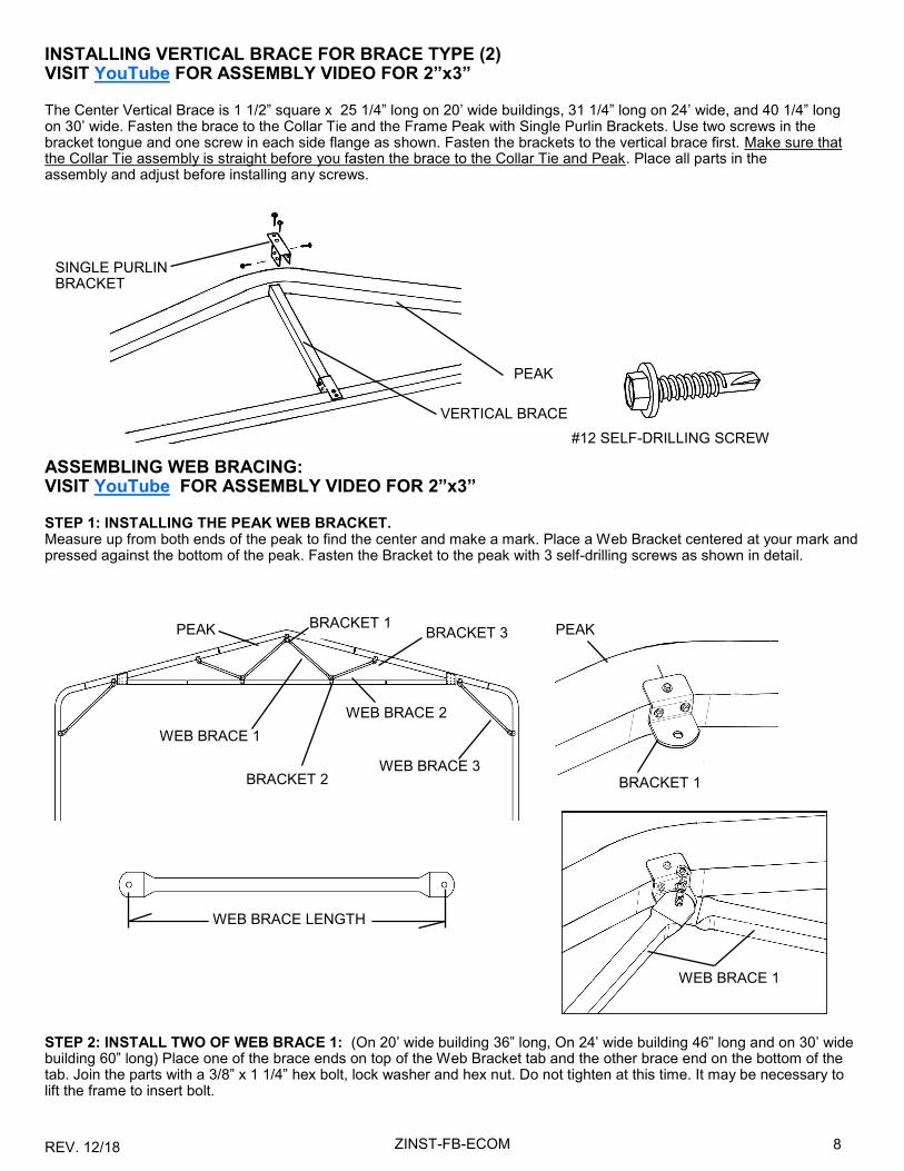
INSTALLING VERTICAL BRACE FOR BRACE TYPE (2) VISIT YouTube FOR ASSEMBLY VIDEO FOR 2”x3” The Center Vertical Brace is 1 1/2” square x 25 1/4” long on 20’ wide buildings, 31 1/4” long on 24’ wide, and 40 1/4” long on 30’ wide. Fasten the brace to the Collar Tie and the Frame Peak with Single Purlin Brackets. Use two screws in the bracket tongue and one screw in each side flange as shown. Fasten the brackets to the vertical brace first. Make sure that the Collar Tie assembly is straight before you fasten the brace to the Collar Tie and Peak. Place all parts in the assembly and adjust before installing any screws.
#12 SELF-DRILLING SCREW
ASSEMBLING WEB BRACING: VISIT YouTube FOR ASSEMBLY VIDEO FOR 2”x3” STEP 1: INSTALLING THE PEAK WEB BRACKET. Measure up from both ends of the peak to find the center and make a mark. Place a Web Bracket centered at your mark and pressed against the bottom of the peak. Fasten the Bracket to the peak with 3 self-drilling screws as shown in detail.
PEAK
WEB BRACE 1
WEB BRACE 2
WEB BRACE 3
BRACKET 1
BRACKET 1
PEAK PEAK
BRACKET 2
BRACKET 3
STEP 2: INSTALL TWO OF WEB BRACE 1: (On 20’ wide building 36” long, On 24’ wide building 46” long and on 30’ wide building 60” long) Place one of the brace ends on top of the Web Bracket tab and the other brace end on the bottom of the tab. Join the parts with a 3/8” x 1 1/4” hex bolt, lock washer and hex nut. Do not tighten at this time. It may be necessary to lift the frame to insert bolt.
WEB BRACE LENGTH
WEB BRACE 1
VERTICAL BRACE
SINGLE PURLIN BRACKET

REV. 12/18 9 ZINST-FB-ECOM
PEAK WEB BRACKET
WEB BRACE 1
WEB BRACE 2
WEB BRACKET 2
WEB BRACKET 3
LOCATE BRACKET ON COLLAR TIE. INSERT ONE SCREW HERE. UNDO ASSEMBLY AND INSTALL BRACE 3. REINSTALL HARDWARE
STEP 3: INSTALL WEB BRACE 2: (On 20’ buildings 24”) (On 24’ buildings 30”) (On 30’ wide buildings 36”) Loosely attach Web Bracket 2 to the other end of Web Brace 1. Place the Web Bracket on the Collar Tie (make sure the collar tie is straight and fasten the face of the bracket to the collar tie with a self-drilling screw. Remove the hex nut and attach one end of Web Brace 2 to the Web Bracket 2 assembly. ( like the first assembly, one brace end should be on one side of the web bracket tab and one on the other.) Now, Loosely attach Web Bracket 3 to the other end of Web Brace 2 and fasten the bracket to the under side of the rafter. Repeat assembly for remaining Web Brace 2.
STEP 4: ASSEMBLING WEB BRACE 3: WEB BRACE 3 IS 24” LONG ON ALL BUILDINGS. Locate the edge of the web bracket at the end of the side post as shown. Attach the upper Web Bracket with 3 self-drilling screws. Now, fasten Web Brace 3 to the upper Web Bracket with a hex bolt, lock washer and hex nut. (Do not tighten at this time) Loosely attach a Web Bracket to the lower end of Web Brace 3 and place it against the side post. Re-check the build-ing dimension across the bottom of the frame 20’, 24’, or 30’ before attaching lower bracket to side post. Now, attach the face to the side post with a screw, remove the hex nut, let the bolt drop down and install the two screws in the side of the Web Bracket. Now, reinstall the bolt, lock washer and nut. Repeat assembly for remaining Web Brace 3 on the other side of the frame. When all bracing is in place, tighten hardware. The nut size is 9/16”. You may also need to hold the bolt head with pliers.
WEB BRACE 3
UPPER WEB BRACKET
LOWER WEB BRACKET
INSTALL THIS SCREW FIRST IN FACE
INSTALL THIS SCREW FIRST IN FACE
SIDE POST
WEB BRACKET 3
1"

REV. 12/18 10 ZINST-FB-ECOM
HAT CHANNEL USED FOR MARKING
STAKES
STEP 5: MARKING THE HAT CHANNEL PLACEMENT ON THE FRAMES AHEAD OF TIME Once you have the trusses assembled take time to stack them on top of each other, ensuring that the top of all of the frames are squared up and all joints lined up. Utilizing stakes to hold them secure. Now refer to your Care Package for the on-center spacing of your hat channel. Use one of the pieces of hat channel to mark the location on the roof frame surface. Do not cut any hat channel. Mark the outside locations at the eave corner. Next, mark the on-center spacing according to your Care Package, use the on-center marks and center the hat channel vertically as shown in the illustration. Then mark a line across the trusses locating both edges of the hat channel. You can measure and locate each hat channel as you go or mark the locations of all the channels as previously mentioned. *In the event that the previous step was missed you are still able to mark the hat channel locations on the front and back frame sections and snap a chalk line the length of the building to mark the hat channel locations on all of the interior frame sections, this is more challenging though, and you must ensure the trusses are level and plum. Hat cannel installation will be addressed later. These steps are meant to save you time and cre-ate a better building experience.
STEP 6: INSTALLING ROOF/WALL FRAMES SECTIONS TO BASE RAILS NOTE: This assembly will require at least two people. 24’ and 30’ frames may require more. When raising a larger frame, the third person can walk the center of the frame up a ladder placed inside the carport. Start at one end of the building and place a Roof/Wall frame assembly (one with no truss brace) on the first base rail vertical pins. Fasten joints with two screws each. Keep the screw heads away from the outside of the building where sheet metal may be installed. Check the bottom ends of the side posts or height extensions for dimples that might interfere with assembly to base rail pins. Dimples must be removed. (See page 2.) Repeat this assembly until all Roof/Wall frame assemblies are installed.

REV. 12/18 11 ZINST-FB-ECOM
#12 SELF-DRILLING SCREW
Before you install sheet metal, you may want to check the Roof/Wall assemblies to make sure they are plumb and square and that the side post heights are equal. To do this, first check the front and back Roof/Wall sections to make sure that they are plum side to side. Check the outside of the side post. If adjustments must be made, you can drive a wooden or metal stake into the ground about 8’ from the building and use a Motor Cycle strap or Ratchet strap to pull the side post into plumb. Place a clamp on the side post as shown and attach the strap above the clamp. When the front and back sections are plumb (side to side), tie two strings from the front side post to the back side post at the bottom and top of the bend radius as shown. These strings will let you see which sections are high, low or out of plumb. If the side posts are high or low, remove the joint screws and raise the low posts and hammer down the higher posts as much as possible. Reinstall the screws in a new location. Check the height of the side posts on both sides of the building. The straps should remain in place until several runs of roof metal have been installed. Note: This is not a critical step, but it may improve the appear-ance of your building. If side posts are out of plane with the other side posts more than 1/4”, it may be visible.
SQUARING UP YOUR FRAME
CLAMP
MOTOR CYCLE STRAP
HAMMER
STRING
SIDE POST
STEP 6: (continued) Place bottom of side posts on base rail pins at an angle. Raise frame section and drop it onto pins at the same time on both sides of the carport. Tap lightly on the side post with a hammer if parts do not drop into place.
BASE RAIL PIN
NOTE THAT THE END FRAME SECTIONS DO NOT HAVE TRUSS BRACES.

REV. 12/18 12 ZINST-FB-ECOM
STEP 7: INSTALLING BACK BASE RAILS Layout the Base Rail components as shown in the illustration of your building size. Note that all back frame components are 2” x 2” square tubing. See illustration below for length dimensions of base rail tubes. The base rail assembly is made up of straight length 2” square tubes and T-Connectors. When you have all of the base rail assembly together place the assembly between the back side base rails of the building. Fasten the end base rails to the pins of the side base rails with Angle rack-ets. The spaces between the vertical pins should be equal. (12’ wide building 68” space, 20’ wide building 57”, 24’ wide building 69” and 30’ wide building 69 1/4”.) Fasten joints with two 1” self-drilling screws on top of the base rail. Anchor the T-Connectors to the concrete slab or footing as you did the side base rails with 1/2” x 7” wedge anchors.
STEP 8: INSTALLING BACK VERTICALS The Back Vertical is a 2” x 2” x 81 3/4” tube with one swaged (reduced) end. The Vertical Extensions are 2” square tubes. The length is shown in the illustration below. Join the Back Verticals and the appropriate Vertical Extensions. (do not install screws at this time) Place the assemblies on the base rail pins, plumb the assembly, slide the extension tube up to touch the rafter or peak and attach it with a Flat Bracket on the inside of the building. It may help to attach the flat bracket to the verti-cal extension before you install the assembly. Let 2” of the bracket extend beyond the end of the extension.
T-CONNECTOR
T-CONNECTOR 3 PLACES
T-CONNECTOR 3 PLACES
T-CONNECTOR 5 PLACES
BACK VERTICAL
BACK VERTICAL 3 PLACES
BACK VERTICAL 5 PLACES (2) ON CENTER VERTICAL IF 12’H, (6) TOTAL
EXTENSION ON: 8’ HIGH—25 1/2” 10’ HIGH—49 1/2”
BACK VERTICAL 3 PLACES
EXTENSION ON: 8’ HIGH—23” 10’ HIGH—47”
37” LONG 2 PLACES
47” LONG 2 PLACES
EXTENSION ON: 8’ HIGH—37 1/2” 10’ HIGH—61 1/2”
57 3/4” 2 PLACES
49” LONG 2 PLACES
59” LONG 2 PLACES
EXTENSION ON: 8’ HIGH—43 1/2” 10’ HIGH—67 1/2”
EXTENSION ON: 8’ HIGH—26” 10’ HIGH—50”
47 1/4” LONG 2 PLACES
37 1/4” LONG 3 PLACES
EXTENSION ON: 10’ HIGH—46 3/4” 12’ HIGH—71”
EXTENSION ON: 10’ HIGH—61 3/4” 12’ HIGH—85 3/4”
FLAT BRACKET TYPICAL ON ALL BUILDINGS (ON INSIDE OF BUILDING)
30’ WIDE
24’ WIDE
12’ WIDE 20’ WIDE
#12 SELF-DRILLING SCREW
TYPICAL
EXTENSION ON: 10’ HIGH—76 1/2” 12’ HIGH—23 3/4”

REV. 12/18 13 ZINST-FB-ECOM
STEP 9: INSTALLING FRONT BASE RAILS AND VERTICALS GARAGE DOORS: THE BASIC GARAGE BUILDING COMES WITH 1 GARAGE (OR OVERHEAD) DOOR OPENING. 30’ WIDE BUILDINGS HAVE A DOUBLE DOOR OPENING. DOOR SIZES: 12’ Wide-9’ Door, 20’ Wide-16’ Door, 24’ Wide-16’ Door, 30 Wide-16’ Door. The care package for the specific building you bought will also have end wall designs with part call outs. Find the illustration that matches your building size and door style. Join the Base Rail tubes and (L) or (U) connectors as shown. The Base Rails are all 2” square tubes. See illustration for tube length. Measure and mark the location for the base rails and anchor the L & U connectors with expansion bolts as you did the side base rails. NOTE: Leave the nuts slightly loose so you can install the vertical tubes. Attach the end base rails to the side base rail pins with Angle brackets as you did on the back base rail ends after the vertical tubes are installed. The door openings should be 9’ wide or 16’ wide. Assemble the Door Vertical Tubes (see drawing for parts and location). Attach a Flat Bracket at the top as shown and stack the vertical Door Jamb tubes on the L-Connectors or U-Connectors as shown. Plumb the Door Jambs and attach the top portion of the assembly to the rafter or peak. Note that the Flat Bracket should be on the inside of the building. Be sure to leave a space between the Door Jambs of 9’ or 16’ to install the door header. Assemble the Door Header components as listed in the illustration and fasten them to the Door Jambs with Angle Brackets on the top of the header. The basic garage door header height is 7’ you may have chosen to install a taller door. Set the height at the bottom of your door header at 7’ or the height of your chosen door. Now, install the vertical Header Brace in the center above the Door Header with 2 Angle Brackets at the bottom and a Flat Bracket at the top on the inside of the building. The brace should be plumb. You may find it easier to attach the brackets to the header brace on the ground (see detail). (NOTE: If you are installing a taller door than 7’ you will need to cut the Vertical Header Brace to fit your door height.
7’ or 8’
9’
VERTICAL (DOOR JAMB) 2” X 3” X 78 3/4” (2 PLACES)
FLAT BRACKET (3 PLACES)
L-CONNECTOR (2 PLACES)
BASE RAIL 2” X 2” X 6” (2 PLACES)
ANGLE BRACKET (6 PLACES)
HEADER TUBE WITH SWAGE 2” X 3” X 64 3/4”
VERTICAL HEADER BRACE 8’ HIGH 2” X 2” X 23 1/2” 10’ HIGH 2” X 2” X 47 1/2”
DOOR HEADER 2” X 3” X 48”
BASE RAIL 2” X 2” X 12” (2 PLACES)
VERTICAL HEADER BRACE 8’ HIGH 2” X 2” X 35 1/2” 10’ HIGH 2” X 2” X 59 1/2”
FLAT BRACKET (3 PLACES)
DOOR HEADER 2” X 3” X 37”
TUBE WITH SWAGE 2” X 3” X 81 3/4” (4 PLACES)
ANGLE BRACKET (6 PLACES)
L-CONNECTOR (2 PLACES)
7’ or
16’
20’ WIDE GARAGE
12’ WIDE GARAGE
HEADER BRACE TO PEAK
BASE RAIL TO SIDE BASE RAIL PIN
ON INSIDE OF BUILDING
HEIGHT EXTENSION 2’ FOR 10’ HIGH GARAGE 2” X 3” X 28 3/4” (1) SWAGE 4’ NONE ON 8’ HIGH GAR-AGE (2 PLACES)
FOR 10’H 2” X 3” X 27 3/4” (1) SWAGE 4’ NONE ON 8’ HIGH GARAGE (2 PLACES)
LEAVE NUT LOOSE UNTIL VERTICALS ARE INSTALLED
DOOR VERTICAL ASSEMBLY
2”
SEE BUILDING DRAWING FOR VERTICAL PART LOCATION
L-CONNECTOR & BASE RAIL DETAIL. MOUNT U- CONNECTORS THE SAME
FOR 8’H 2” X 3” X 80” FOR 10’H TUBE WITH SWAGE 2” X 3” X 81 3/4” (4 PLACES)

REV. 12/18 14 ZINST-FB-ECOM
INSTALLING FRONT ENCLOSURE CONTINUED
VERTICAL (DOOR JAMB) 2” X 3” X 86 1/4” (2 PLACES)
FLAT BRACKET (3 PLACES)
VERTICAL HEADER BRACE 8’ HIGH 2” X 2” X 41 1/2” 10’ EIGH 2” X 2” X 65 1/2”
BASE RAIL 2” X 2” X 36” (2 PLACES)
L-CONNECTOR (2 PLACES)
7’ or 8’
16’
DOOR HEADER 2” X 3” X 37”
ANGLE BRACKET (6 PLACES)
HEADER BRACE TO PEAK
BASE RAIL TO SIDE BASE RAIL PIN ON INSIDE OF
BUILDING
ANGLE BRACKET (10 PLACES)
L-CONNECTOR (2 PLACES)
BASE RAIL 2” X 2” X 11 3/4” (2 PLACES)
U-CONNECTOR
VERTICAL (DOOR JAMB) 2” X 3” X 80” (2 PLACES)
VERTICAL (DOOR JAMB) 2” X 3” X 81 3/4” WITH SWAGED (REDUCED) END (2 PLACES)
VERTICAL (DOOR JAMB) EXTENSION 8’ GARAGE 2” X 3” X 30 3/4” 10’ GARAGE 2” X 3” X 54 3/4” (2 PLACES)
VERTICAL HEADER BRACE 8’ HIGH 2” X 2” X 25” 10’ HIGH 2” X 2” X 49” (2 PLACES)
7’ or 8’
9’
DOOR HEADER 2” X 3” X 48” 1 ON EACH DOOR
FLAT BRACKET (3 PLACES)
24’ WIDE GARAGE DOUBLE DOOR
24’ WIDE GARAGE SINGLE DOOR
HEIGHT EXTENSION 2’ FOR 10’ HIGH GARAGE 2” X 3” X 28 3/4” (1) SWAGE 4’ NONE ON 8’ HIGH GARAGE (2 PLACES)
HEIGHT EXTENSION 2’ FOR 10’ HIGH GARAGE 2” X 3” X 28 3/4” (1) SWAGE 4’ NONE ON 8’ HIGH GARAGE (2 PLACES)
HEADER TUBE WITH ONE END SWAGED 2” X 3” X 81 3/4”
HEADER TUBE WITH ONE END SWAGED 2” X 3” X 64 3/4” (1 ON EACH DOOR)

REV. 12/18 15 ZINST-FB-ECOM
INSTALLING FRONT ENCLOSURE CONTINUED
VERTICAL (DOOR JAMB) 2” X 3” X 95” (2 PLACES)
HEIGHT EXTENSION 2’ FOR 10’ HIGH GARAGE 2” X 3” X 28 3/4” (1) SWAGE 4’ FOR 12’ HIGH GARAGE 2” X 3” X 52 3/4” (1) SWAGE NONE ON 8’ HIGH GARAGE
FLAT BRACKET (3 PLACES)
VERTICAL HEADER BRACE 8’ HIGH 2” X 2” X 50 1/2” 10’ HIGH 2” X 2” X 74 1/2” 12’ HIGH 2” X 2” X 98 1/2”
HEADER TUBE WITH ONE END SWAGED 2” X 3” X 81 3/4”
BASE RAIL 2” X 2” X 72” (2 PLACES)
L-CONNECTOR (2 PLACES)
7’ or
16’
DOOR HEADER 2” X 3” X 37”
ANGLE BRACKET (6 PLACES)
HEADER BRACE TO PEAK
BASE RAIL TO SIDE BASE RAIL PIN ON INSIDE OF
BUILDING
ANGLE BRACKET (10 PLACES)
L-CONNECTOR (2 PLACES)
BASE RAIL 2” X 2” X 35 3/4” (2 PLACES)
BASE RAIL 2” X 2” X 29 3/4
VERTICAL (DOOR JAMB) 2” X 3” X 86 1/4” (2 PLACES)
VERTICAL (DOOR JAMB) 2” X 3” X 81 3/4” WITH SWAGED (REDUCED) END (2 PLACES)
VERTICAL (DOOR JAMB) EXTENSION 8’ GARAGE 2” X 3” X 36 5/8” 10’ GARAGE 2” X 3” X 60 5/8” 12’ GARAGE 2” X 3” X 84 5/8” (2 PLACES)
VERTICAL HEADER BRACE 8’ HIGH 2” X 2” X 31 1/4” 10’ HIGH 2” X 2” X 55 1/4” 12’ HIGH 2” X 2” X 79 1/4” (2 PLACES)
7’ or
9’
HEADER TUBE WITH ONE END SWAGED 2” X 3” X 64 3/4” (1 ON EACH DOOR)
DOOR HEADER 2” X 3” X 48” 1 ON EACH DOOR
FLAT BRACKET (3 PLACES)
30’ WIDE GARAGE DOUBLE DOOR
30’ WIDE GARAGE SINGLE DOOR
HEIGHT EXTENSION 2’ FOR 10’ HIGH GARAGE 2” X 3” X 28 3/4” (1) SWAGE 4’ FOR 12’ HIGH GARAGE 2” X 3” X 52 3/4” (1) SWAGE NONE ON 8’ HIGH GARAGE

REV. 12/18 16 ZINST-FB-ECOM
STEP 10: ASSEMBLE SIDE WALK DOOR FRAME (CUT OUT BASE RAIL) VISIT YouTube FOR WALK DOOR TRIM APPLICATION VIDEO The Door Frame consists of a Header Tube 2” x 3” x 57 3/4” long (69 3/4” for 6’ OC) and a Door Jamb 2” x 3” x 81 3/4”. These combine with the side post to create the frame for your door. The following assembly instructions will be for the flange mounted door that is available from VersaTube. The door will open to the outside of the building. The first step is to choose the frame bay (opening) where you want to install the door. The door will be located in the frame to the side away from the anchor bolt. Do not chose an opening with two anchor bolts. We recommend that the base rail be cut out where the door will be located. This will allow the threshold portion of the door frame to sit down on the slab and not cause a trip issue. To cut out the base rail, use a metal cutting blade in a reciprocating saw. Mark a line on the base rail 37 3/8” from the side post. Place the line on the top and the side of the base rail. Now, with the reciprocating saw, cut the base rail 3/16” from the side post (as close as you can to the weld) then cut the base rail at your marked line. Remove the section of base rail and you are ready to install the door. Place the door in the opening to check the fit. The door will open to the outside. Cut the 2” x 3” x 81 3/4” door jamb tube down to 79 3/4”. (If you are not cutting out the base rail, do not cut down the jamb post) You can use a metal cutting blade or an abrasive disk in your saw to cut the tube. Pre-attach a flat bracket to one end of the door jamb tube on the 2” side of the tube. Allow 2” of the bracket to hang over the end of the tube. The bracket will be attached on the inside of the building to the base rail. Attach a angle bracket to the top of the tube flush with the end and centered in the 3” side of the tube. Before you attach the angle bracket, set the tube in place and make sure that the flat bracket is on the in-side of the building and the angle bracket is facing away from the door opening. Attach the brackets with #12 x 3/4” self-drilling screws. Attach an angle bracket to both ends of the header tube. Let the brackets extend 1/8” past the ends of the tube. The outside to outside dimension on the brackets should be 58” for 70” on center frames.
DOOR HEADER TUBE 2X3X45 3/4” OR 57 3/4” ANGLE BRACKET
1/8” Both ends 58” OR 70”
37 3/8”
37 3/16”
DOOR JAMB POST 81 3/4” OR CUT DOWN TO 79 3/4” FOR DOORS WITH CUT AWAY BASE RAIL.
FLAT BRACKET TO INSIDE OF BUILDING
FIRST CUT CLOSE TO WELD
CENTER ANGLE BRACKET ON 3” SIDE OF TUBE
2” OVERHANG
ANGLE BRACKET
#12 SELF-DRILLING SCREW

REV. 12/18 17 ZINST-FB-ECOM
DOOR INSTALLATION STEPS IMPORTANT: The door is designed to allow a left hand or right hand opening. You can flip the door upside down to change the direction that the door opens. A snap in cover plate is provided to snap into the end at the top of the door. Place the door with frame into the opening. Clamp the door to the building side post to hold it in place. Place the door jamb post on the other side of the door against the door frame. Attach the flat bracket at the bottom of the post to the base rail. The post will sit on the base rail. Place the header tube on top of the door frame. Check the door for plumb, flush the ends of the header with the building side posts and attach the angle brackets at the ends to the building side posts. Check the door again for plumb and attach the angle bracket at the top of the door jamb post to the bottom of the door header.
ATTACHING THE DOOR TO THE FRAME Recheck the door for plumb and attach the door side flanges to the frame with #10 x 7/8” pan head, square drive screws. (Use a #2 square drive bit to install the screws) Install the screws in the pattern shown below in the illustration.
HOLES ARE PRE-PUNCHED IN DOOR FLANGES. THE LARGER CIRCLES ARE THE SCREW LOCATIONS
#10 X 7/8” PAN HEAD, SELF-DRILLING SCREW SQUARE DRIVE

REV. 12/18 18 ZINST-FB-ECOM
STEP 12: INSTALLING HAT CHANNEL PURLINS ON ROOF OF BUILDING Please See your Care Package that was e-mailed to you, for the location dimensions for the Hat Channel on the roof of the building.
See the chart below for the location dimensions for the Hat Channel on the roof of the building. You can measure and locate each hat channel as you go or mark the locations of all the channels on the front and back frame sections and snap a chalk line the length of the building to mark the hat channel locations on all of the interior frame sections. Before you start the installation of hat channel purlins on the roof we recommend that you brace the one end wall of the building. Make sure that the end wall is plumb and attach angle braces from the end wall side posts to the lower portion of the next frame section side posts. You can use wood or metal for this job. Place a brace on both sides of the building. You can clamp the braces in place or use self-drilling screws. If you use screws you may want to mount the braces to the outside of the frame. Braces could also be attached to a wood stake driven into the ground 5’ or 6’ away from the back of the building. With the back wall supported, you can measure and note the distances from one frame to the next at the base rail and use that dimension to position the frames at the top of the building as you install the hat channel purlins. The frames should be on 4’ or 5’ centers. Attach the hat channel to the frame with #12 x 3/4” self-drilling screws. See the illustrations on the next page for purlin location and joint details.
ALTERNATIVE BRACE TO THE OUTSIDE OF THE STRUCTURE.
CLAMP OR SCREW BRACES TO FRAME
12’ WIDE 20’ WIDE 24’ WIDE 30’ WIDE
BUTT JOINT Where two pur-lins come togeth-er.
1”
FLUSH
ATTACH HAT CHANNEL TO FRAME WITH #12 X 3/4” SELF-DRILLING SCREWS
START HAT CHANNEL 1” FROM END OF FRAME

REV. 12/18 19 ZINST-FB-ECOM
STEP 13: INSTALLING SIDE METAL PANELS The sheet metal panels provided by VersaTube will be 12’2” long if your building is on 6’ centers. If you building is on 5’ frame centers the side panels will be 10’-2” long. Start your first run of sheet metal panels at the eave corner of the building. Start at the back of the building. The sheet metal panels have an under lap and an overlap edge. The under lap edge is a complete rib with a small flange. The overlap edge is a partial rib. The under lap edge will always be place to the top and the overlap edge to the bottom. Use #12 x 1” painted, self-drilling screws to install sheet metal panels.
OVERLAP EDGE
UNDER LAP EDGE
UNDER LAP EDGE FLUSH WITH COR-NER BRACKET
Place screws about 1” from the major ribs as shown. Do not install screws above the bottom rib until the next course of sheet metal is installed.
No screws above bottom rib until next lower panel is installed.
#12 x 1” PAINTED, SELF-DRILLING SCREW
Do not install screws at the end of the panel until the next panel is in place. Lap panel two 2” over panel one.

REV. 12/18 20 ZINST-FB-ECOM
INSTALLING ADDITIONAL COURSES OF SIDE METAL PANELS
When you have completed the installation of the first course of side wall panels at the eave of the building, start the second course at the same end of the building. Insert the under lap edge of the panels under the overlap edge of the panels in the first course. Attach the panels with screws as you did the first course of panels. Once again, leave the screws out of the low-er edge so you can insert the lower course of panels. Continue installing panels until you get to the last course at the bottom of the side wall. You will probably have to cut the last course of panels to fit. Take a measurement from the center of the lower edge to the bottom of the base rail. Subtract about 1/8” from that measurement. Now, mark the lower panel on the un-der side of the panel. Cut the length of the panel with a circular saw with a metal cutting blade. (The good side of the panel should be facing down when you make the cut. Make sure you are wearing eye and ear protection when you cut these pan-els. Repeat the installation of side panels on the other side of the building.
LOWER PANEL
UNDER LAP EDGE
Measurement –1/8”
Measure lower panels from center of under lap edge rib. Mark on the under side of the panel and cut the panel with the good side down.

REV. 12/18 21 ZINST-FB-ECOM
STEP 14: INSTALLING BACK WALL SHEET METAL PANELS The length of the sheet metal panels for the back end wall will vary depending on the building width, Panels will be sized to overlap at one of the vertical frame members, typically the center frame member. In order to get the ribs on the end wall to line up with the side wall panels we recommend that you start your first run (course) of sheet metal panels at the eave corner of the building with the ribs on the back of the building matching up with the ribs on the side wall. You may want to measure up from the bottom of the building or snap a chalk line from one side to the other to make sure that the first course of panels is straight and level. Remember to place the under-lap edge to the top. Panels installed above the first course will have to be market on the back and trimmed to be flush with the top of the hat channel roof purlins. The under lap edge of lower panels will slid under the overlap edge of the course above so do not install screws above the lower rib on the higher course of panels until the lower course has been installed. Trim the bottom course to fit just above the bottom of the base rail.
SIDE WALL SHEET METAL TOP RIB
MATCH END WALL PANEL RIB TO SIDE WALL RIB AT BOTH EAVE CORNERS
SCRAP SCRAP
TRIM TO FIT AT BOTTOM
INSTALL THIS PANEL OR PANEL COURSE FIRST
SET THIS TOP PANEL IN PLACE. MARK ON THE BACK AT THE TOP OF THE HAT CHANNEL. REMOVE THE PANEL AND CUT. SCREW PANEL IN PLACE BACK WALL PANEL LAYOUT
REV. 12/18 22 ZINST-FB-ECOM
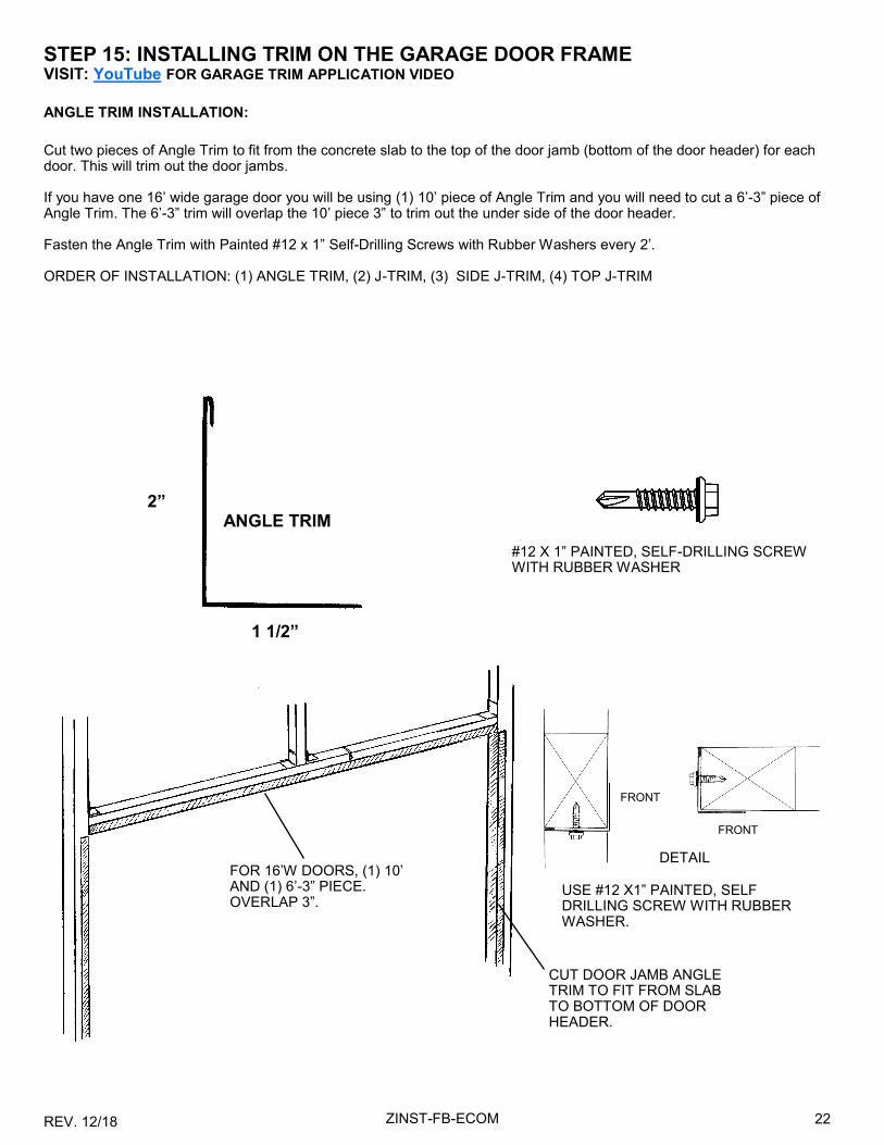
STEP 15: INSTALLING TRIM ON THE GARAGE DOOR FRAME VISIT: YouTube FOR GARAGE TRIM APPLICATION VIDEO
ANGLE TRIM INSTALLATION:
Cut two pieces of Angle Trim to fit from the concrete slab to the top of the door jamb (bottom of the door header) for each door. This will trim out the door jambs. If you have one 16’ wide garage door you will be using (1) 10’ piece of Angle Trim and you will need to cut a 6’-3” piece of Angle Trim. The 6’-3” trim will overlap the 10’ piece 3” to trim out the under side of the door header. Fasten the Angle Trim with Painted #12 x 1” Self-Drilling Screws with Rubber Washers every 2’. ORDER OF INSTALLATION: (1) ANGLE TRIM, (2) J-TRIM, (3) SIDE J-TRIM, (4) TOP J-TRIM
2”
1 1/2”
ANGLE TRIM
FOR 16’W DOORS, (1) 10’ AND (1) 6’-3” PIECE. OVERLAP 3”.
CUT DOOR JAMB ANGLE TRIM TO FIT FROM SLAB TO BOTTOM OF DOOR HEADER.
DETAIL
USE #12 X1” PAINTED, SELF DRILLING SCREW WITH RUBBER WASHER.
FRONT
FRONT
#12 X 1” PAINTED, SELF-DRILLING SCREW WITH RUBBER WASHER
REV. 12/18 23 ZINST-FB-ECOM
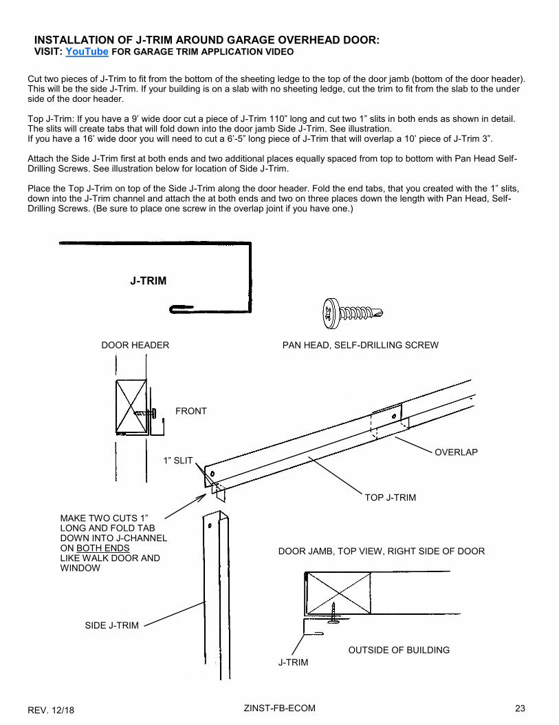
INSTALLATION OF J-TRIM AROUND GARAGE OVERHEAD DOOR: VISIT: YouTube FOR GARAGE TRIM APPLICATION VIDEO
Cut two pieces of J-Trim to fit from the bottom of the sheeting ledge to the top of the door jamb (bottom of the door header). This will be the side J-Trim. If your building is on a slab with no sheeting ledge, cut the trim to fit from the slab to the under side of the door header. Top J-Trim: If you have a 9’ wide door cut a piece of J-Trim 110” long and cut two 1” slits in both ends as shown in detail. The slits will create tabs that will fold down into the door jamb Side J-Trim. See illustration. If you have a 16’ wide door you will need to cut a 6’-5” long piece of J-Trim that will overlap a 10’ piece of J-Trim 3”. Attach the Side J-Trim first at both ends and two additional places equally spaced from top to bottom with Pan Head Self-Drilling Screws. See illustration below for location of Side J-Trim. Place the Top J-Trim on top of the Side J-Trim along the door header. Fold the end tabs, that you created with the 1” slits, down into the J-Trim channel and attach the at both ends and two on three places down the length with Pan Head, Self-Drilling Screws. (Be sure to place one screw in the overlap joint if you have one.)
J-TRIM
OUTSIDE OF BUILDING
FRONT
DOOR HEADER
MAKE TWO CUTS 1” LONG AND FOLD TAB DOWN INTO J-CHANNEL ON BOTH ENDS LIKE WALK DOOR AND WINDOW
1” SLIT
PAN HEAD, SELF-DRILLING SCREW
DOOR JAMB, TOP VIEW, RIGHT SIDE OF DOOR
TOP J-TRIM
OVERLAP
J-TRIM
SIDE J-TRIM

REV. 12/18 24 ZINST-FB-ECOM
STEP 16: INSTALLING FRONT WALL SHEET METAL PANELS The length of the sheet metal panels for the front end wall will vary depending on the building width. Panels will typically be half the width of the building plus 1”. This will allow the panels to overlap 2” at the center frame member. In order to get the ribs on the end wall panels to line up with the side wall panels we recommend that you start your first run (course) of sheet metal panels at the eave corner of the building with the ribs on the front of the building matching up with the ribs on the side wall. You may want to measure up from the bottom of the building or snap a chalk line from one side to the other to make sure that the first course of panels is straight and level. Remember to place the under-lap edge to the top. The first panel that you install will have to be trimmed to fit the top of the door opening. Set the panel in place with both ends matched up with the top ribs on the side panels if you have full length sheet metal panels or with the chalk line if you have two or more panels. Mark the door opening on the inside of the panel. Subtract about 1/4” from the line that you mark and cut the panel with your tin snips and your circular saw with a metal cutting blade. Install the panel with screws above each major rib. Do not install screws above the bottom rib until the next lower panel is installed. Set the top course of panels in place, mark and cut them as you did the top panel/panels on the back of the building. Install the panel/panels. Now measure the distance from the edge of the building frame to the door opening, subtract 1/4”. This will be the length of the lower panels on the sides of the garage door opening. Insert and attach the lower panels on both sides of the door opening. These panels will slide into the J-Trim around the door. You will have to trim the bottom panels to fit before they are installed.
INSTALL THIS PANEL FIRST
SCRAP SCRAP
SCRAP
SCRAP SCRAP
4’ PANELS

REV. 12/18 25 ZINST-FB-ECOM
STEP 17: CORNER TRIM Before you install the corner trim you must install Outside Foam Closures. The foam closured are grey foam strips with Notches cut out to match the contour of the sheet metal panel ribs. The closures have an adhesive strip on one surface. Peal off the protective paper and install the strips to the sheet metal panels in the corners of the building as shown. The corner trim for your building is angle trim 3” x 3” x 10’ long. If your building is 10’ at the eave you will not have to cut the corner trim. If your building is under 10’ at the eave cut the trim to fit. If your building is over 10’ you will have to cut 4 extension pieces of trim and overlap them as shown below. Cut the extension to allow about 5” of overlap. Place the ex-tension pieces on all 4 corners of the building at the bottom. Screw the trim to the building with #12 x 1” self-drilling screws painted the color of the trim. Place the screws in the trim to hit the center of every other major rib in the sheet metal panels. Do not install screws at the top of the angle until a longer 10’ piece is installed. Now place a 10’ piece of trim on each corner of the building with the top of the trim 1” above the top of the side sheet metal. The trim should over-lap the 30” piece of trim at the bottom about 5”. Attach with screws in the center of every other rib as shown.
3”
3”
30” LONG PIECE OF ANGLE TRIM
10’ PIECE OF ANGLE TRIM WILL OVERLAP 30” TRIM ABOUT 5”
TRIM AT TOP WILL EXTEND ABOUT 1” ABOVE THE SIDE METAL
3” X 3” ANGLE TRIM
TOP VIEW
OUTSIDE CLOSURE ON ALL 4 CORNERS OF THE BUILDING

REV. 12/18 26 ZINST-FB-ECOM
STEP 18: EAVE TRIM The eave trim for your building is 3” x 3 1/2” x 10’ long. See the drawing below left for the trim shape. Start the application of eave trim at the back of the building. Place a 10’ pieces of trim at the eave of the building as shown below, square the trim to the building and attach it to the top of the hat channel with #10 x 7/8” pan head, self-drilling, square drive screws. Place the first screw 10” from the end of the trim and additional screws every 36”. Check as you go to keep the trim square and flush with the sheet metal side panels. You will need additional trim to get to the front of the building. Place additional trim pieces over the first piece. Allow about 3” of overlap. You will have to cut the last piece to length. The end of the trim should be flush with the corner trim as shown below. Repeat on the other side of the building.
36”
10”
3 1/2”
3”
#10 PAN HEAD SCREW
END WALL VIEW
PAN SCREWS INTO TOP OF HAT CHANNEL
EAVE TRIM
CORNER TRIM
SIDE WALL
EAVE TRIM OVERLAP
3”
REV. 12/18 27 ZINST-FB-ECOM
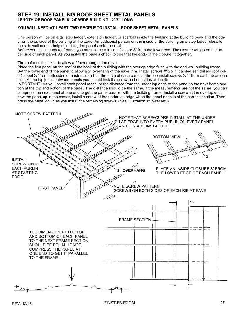
STEP 19: INSTALLING ROOF SHEET METAL PANELS LENGTH OF ROOF PANELS: 24’ WIDE BUILDING 12’-7” LONG
YOU WILL NEED AT LEAST TWO PEOPLE TO INSTALL ROOF SHEET METAL PANELS
One person will be on a tall step ladder, extension ladder, or scaffold inside the building at the building peak and the oth-er on the outside of the building at the eave. An additional person on the inside of the building on a step ladder close to the side wall can be helpful in lifting the panels onto the roof. Before you install each roof panel you must place a Inside Closure 3” from the lower end. The closure will go on the un-der side of each panel. As you install the panels check to see that the ends of the closure fit together. The roof metal is sized to allow a 2” overhang at the eave. Place the first panel on the roof at the back of the building with the overlap edge flush with the end wall building frame. Set the lower end of the panel to allow a 2” overhang of the eave trim. Install screws #12 x 1’ painted self drillers roof col-or) about 3/4” on both sides of each major rib at the eave of each panel at the top install screws 3/4” from each rib on one side. At the lap joints between panels you should install a screw on both sides of the rib. IMPORTANT: As you install each panel measure the distance from the under lap edge of the panel to the next frame sec-tion at the top and bottom of the panel. The distance should be the same. If the measurements are not the same, you can compress the next panel at one end to get the panel parallel with the building frame. Install a screw at the overlap end, bow the panel up in the center, install a screw at the under lap edge when the panel edge is at the correct location. Then press the panel down as you install the remaining screws. (See illustration at lower left.)
2” OVERHANG
FIRST PANEL NOTE SCREW PATTERN SCREWS ON BOTH SIDES OF EACH RIB AT EAVE
NOTE SCREW PATTERN
THE DIMENSION AT THE TOP AND BOTTOM OF EACH PANEL TO THE NEXT FRAME SECTION SHOULD BE EQUAL. IF NOT, COMPRESS THE PANEL AT ONE END TO GET IT PARALLEL TO THE FRAME.
FRAME SECTION
NOTE THAT SCREWS ARE INSTALL AT THE UNDER LAP EDGE INTO EVERY PURLIN ON EVERY PANEL AS THEY ARE INSTALLED.
INSTALL SCREWS INTO EACH PURLIN AT STARTING EDGE
PLACE AN INSIDE CLOSURE 3” FROM THE LOWER EDGE OF EACH PANEL
3”
BOTTOM VIEW

REV. 12/18 28 ZINST-FB-ECOM
INSTALLING THE REMAINING PANELS Place the overlap edge of the next roof panel over the under lap edge of the previous panel. Line the panel up at the bot-tom with the previous panel and attach that edge at the top and bottom of the panel. Now, take the same measurements that you did on the first panel from the panel edge to the next frame section. If the panel is not parallel to the frame sec-tion make the correction and fasten the panel as you did the previous panel to the purlins. Repeat this installation method down the length of the building. When you install the panels on the other side of the roof, you will have to work the top side of the panels from one side or from the roof on the other side. When all roof panels have been installed you must get up onto the roof and use the installed screws as a guide for locat-ing the purlins. A straight edge or a speed square can help locate the purlins and make the installation of the remaining screws easier. When walking on the roof step on the flats only (not on major ribs) . Step on or very near the pur-lins or frame members. The screws should be a guide to purlin and frame locations.
SPEED SQUARE
STRAIGHT EDGE
USE EXISTING ROOF SCREWS AS A GUIDE. MARK LOCATIONS FOR ADDITIONAL SCREWS WITH A PENCIL.

REV. 12/18 29 ZINST-FB-ECOM
STEP 20: INSTALLING GABLE TRIM GABLE TRIM WILL COME IN 10’ LENGTHS. Before you install the gable trim to the roof of the building run a bead of Butyl Sealant down the under side of the back flange. Start the installation of gable trim with two pieces of trim 10’ long. Place one on one side of the roof and one on the other. The trim should be flush with the lower end of the roof panels. Before you peel off the protective paper on the Butyl Seal-ant place the trim on the gable edge of the building, square the trim with the building and mark the location of the back flange on the roof at several points with a pencil. Now remove the protective paper on the Butyl Sealant and reposition the gable trim on the roof/gable edge. Make sure that the trim is flush with the lower end of the roof sheet metal panels. Screw the trim to the roof with #12 x 1” painted self-drilling screws (roof Color) through the back flange and into the roof at purlin locations. Install the trim on both sides of the roof. Now get another 10’ piece of gable trim and clip the gable trim in the front center and the back flange as shown. Fold the trim so the front flanges overlap. This will go at the peak of the building and the ends of the trim will overlap the 10’ pieces that you just installed. Place a bead of butyl Sealant on the back flange of the peak trim as you did the other trim. Set the trim in place, square it to the building and mark the location with a pencil. Remove the protective paper and install the trim. When all three pieces of trim have been installed screw the trim to the front of the building with screws into the top of each major rib. You will have to place a screw in the peak of the trim where the fold is overlapped. Repeat this assembly on the other gable end.
BUTYL SEALANT
GABLE TRIM
ROOF PANEL
OVERLAP
SCREWS AT EVERY MAJOR RIB
OVERLAP
CUT IN CENTER OF TRIM
CLIP BACK FLANGE TO TOP FLAT
PLACE 1 SCREW IN CENTER OF OVERLAP
FOLD AT PEAK
1” PAINTED, SELF-DRILLING SCREW, WITH RUBBER WASHER
INSTALL THIS 10’ PIECE OF TRIM FIRST ON BOTH SIDE OF THE ROOF
REV. 12/18 30 ZINST-FB-ECOM
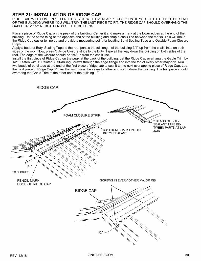
STEP 21: INSTALLATION OF RIDGE CAP RIDGE CAP WILL COME IN 10’ LENGTHS. YOU WILL OVERLAP PIECES 6” UNTIL YOU GET TO THE OTHER END OF THE BUILDING WHERE YOU WILL TRIM THE LAST PIECE TO FIT. THE RIDGE CAP SHOULD OVERHANG THE GABLE TRIM 1/2” AT BOTH ENDS OF THE BUILDING. Place a piece of Ridge Cap on the peak of the building. Center it and make a mark at the lower edges at the end of the building. Do the same thing at the opposite end of the building and snap a chalk line between the marks. This will make the Ridge Cap easier to line up and provide a measuring point for locating Butyl Sealing Tape and Outside Foam Closure Strips. Apply a bead of Butyl Sealing Tape to the roof panels the full length of the building 3/4” up from the chalk lines on both sides of the roof. Now, press Outside Closure strips to the Butyl Tape all the way down the building on both sides of the roof. The edge of the Closure should be 1/4” up from the chalk line. Install the first piece of Ridge Cap on the peak at the back of the building. Let the Ridge Cap overhang the Gable Trim by 1/2”. Fasten with 1” Painted, Self-drilling Screws through the edge flange and into the top of every other major rib. Run two beads of butyl tape at the end of the first piece of ridge cap to seal it to the next overlapping piece of Ridge Cap. Lap the next piece of Ridge Cap 6” over the first, press the seam together and so on down the building. The last piece should overhang the Gable Trim at the other end of the building 1/2”.
PENCIL MARK EDGE OF RIDGE CAP
1/4”
FOAM CLOSURE STRIP
3/4” FROM CHALK LINE TO BUTYL SEALANT
TO CLOSURE
1/2”
SCREWS IN EVERY OTHER MAJOR RIB
RIDGE CAP
RIDGE CAP
2 BEADS OF BUTYL SEALANT TAPE BE-TWEEN PARTS AT LAP JOINT

REV. 12/18 31 ZINST-FB-ECOM
INSTALLING YOUR GARAGE DOOR IN A VERSATUBE FRAME
Note that the Versatube frame is all steel with no overhead ceiling joist. You must deviate from the door manufacturer’s instructions to install the garage door in the Versatube frame. The following is a list of the installation steps that will be different from the door manufacturer’s assembly instructions: 1. It is not necessary for you to frame out your door opening with 2 x 6 lumber. Track brackets will be attached directly
to the steel door frame. 2. If you have a door with torsion springs instead of a extension springs you will need to attach a center vertical over the
door header. 3. You will fasten all brackets an channels to the Versatube frame with #12 self-drilling screws instead of the lag screws
provided with your door. 4. The garage door manufacturer’s instructions call for assembling all of the door sections one at a time and using 3”
nails bent over to hold the sections in place. With the Versatube frame you will assemble only the first or bottom door section and use it as a guide to locate and attach the vertical tracks to the door opening.
TIP: You should have two people to install the garage door. Step 1 Track and Flag Brackets to Vertical Track Install mounting brackets and flag bracket to the vertical rails according to the manufacturer’s instructions. Step 2 Assemble Door Section 1 Assemble door section #1 according to the manufacturer’s instructions including the bottom weather strip, the bottom wheel brackets and the correct hinges. Insert 4 rollers into bottom brackets and hinges and place the first door section in the door opening with the front of the door flush with the back of the door frame. Center the door side to side. One person must hold the door in place or brace it up with something on both sides. Step 3 Installing Vertical Door Tracks Slide the left vertical door track onto the wheels. Use your level to plumb the track and fasten the bottom track bracket to the door frame with a #12 self-drilling screw ( the same screws used to assemble your frame). Plumb the track and attach the next higher bracket to the door frame. Continue to plumb and attach all brackets and flag bracket to the frame with self–drilling screws. When all brackets are installed go back and install one additional screw in each bracket. Repeat this assembly for the right door track.
DOOR OPENING FRAME (JAMB)
GARAGE DOOR CENTERED IN OPENING
BOTTOM BRACKET
ROLLER TRACK
TRACK BRACKET
SELF-DRILLING SCREW

REV. 12/18 32 ZINST-FB-ECOM
Step 4 Installing Additional Door Sections Follow the door manufacturer’s instructions and assemble door section 2. Note that each door section uses a different height hinge at the ends of the door and the same size hinge in the center of the door. When the second door section is assembled, install the rollers and install the door section into the vertical door tracks sliding it down from the top of the tracks. With the section in place attach the door hinges connecting section one to sec-tion two. Repeat this assembly for door section three. If your door is taller than 7’ install all but the top section. The top section will be installed after the horizontal track (and low headroom kit if required) is installed. If the Versatube building that you have has 4’ on center frame spacing you will tie the back of the horizontal tracks up to the rafter above at the end of the tracks. If the your building has the frame sections on 5’ centers you will have to add an extension piece of perforated angle (1 1/2” x 1 1/2” x 16 GA.) to your tracks. This extension will allow you to connect the vertical perforated angle to the rafter above. (See illustration on next page) Perforated angle is not provided. For 5’ on center frames cut the angle lengths to 28”. Measure from the back of the horizontal tracks 8 3/4” and make a mark on the outside of the track. Place the extension angle piece on the track as shown with the end of the angle exten-sion lined up with your mark. Clamp the track and extension angle together and drill two 5/16” hole through the door track using the two of the holes in the perforated angle as a guide. (See illustration) Attach the extension angles to the door tracks with two 5/16” x 3/4” hex head bolts with split lock washers and nuts as shown. Nuts and bolts are not provided.
8 3/4”
19 1/4” for 5’ ON CENTER FRAME
PERFORATED EXTENSION ANGLE
HORIZONTAL DOOR TRACK
5/16” X 3/4” HEX BOLT
NUT
SPLIT LOCK WASHER
DRILL HOLES IN DOOR TRACK
Step 5 Attach the Horizontal Tracks to the Vertical Tracks following the manufacturer’s instructions. If you are attaching a low headroom kit you will also refer to the instructions included with that kit. To temporally support the back of the tracks use a string tied to the back of the perforated angle extensions. You should be able to find a place to lace the string through the sheet metal and over the rafter. If you prefer, you can drive a self-drilling screw into the side of the rafter part way and tie the string to the screw. The back of the perforated angle extension (that you attached to the horizontal tracks) will be fastened vertically to the rafter above with a piece of perforated angle and a brace piece placed at an angle. Use 5/16” x 3/4” hex bolts with lock washers and nuts (not provided) to attach the angle pieces together and #12 x 1” painted self-drilling screws with rubber washer (the same screws you used to attach the sheet metal on the building) to attach the perforated angles to the rafter above. Note: The perforated angle and 5/16” x 3/4” hex bolts, lock washers and nuts are not provided with the garage door or conversion kit. They must be purchased separately. See illustration on next page.

REV. 12/18 33 ZINST-FB-ECOM
ATTACHMENT OF DOOR TRACK WITH & WITHOUT EXTENSION ANGLE TO RAFTER IN BUILDING WITHOUT A LOW HEADROOM KIT INSTALLED.
Before you start, make sure that the tracks are level and square to the front of the building. Use your level to set the track level and measure the diagonals from the back of one track to the front of the other. The diagonals must be equal. See illustration in door manufacturer’s instructions.
Cut a piece of perforated angle to fit vertically as shown and fasten it to the back of the track, or the extension angle, with a 5/16” x 3/4” hex bolt, lock washer and nut. Fasten the top portion to the rafter with two Painted self-drilling screws with rubber washers (the same screws you used to attach the sheet metal to your building). Now, cut a piece of perforated angle to create an angle brace as shown and attach it to the track extension just above the extension with a 5/16” x 3/4” hex bolt, lock washer and nut. Attach the brace to the rafter with a painted self-drilling screw.
IF YOUR BUILDING HAS FRAME SECTIONS ON 4’ CENTERS, YOU WILL NOT NEED A PERFORATED TRACK EXTENSION. YOU WILL ATTACH THE END OF THE DOOR TRACK TO THE RAFTER WITH A VERTICAL BRACE AND AN ANGLE BRACE AS SHOWN ABOVE RIGHT. THE VERTICAL BRACE WILL ATTACH TO THE LARGE HOLE AT THE BACK OF THE DOOR TRACK.
ATTACHING THE SPRING HOOK (EYE BOLT) The spring hook should be attached to the vertical brace about 12” above the track extension. Place a flanged, locking hex nut on the eye bolt the full extension of the threads with the flange to the rear. Insert the bolt through the vertical brace and install another flanged hex nut as shown. Tighten the nuts.
#12 x 1” PAINTED SELF-DRILLING SCREW WITH RUBBER WASHER
5/16” X 3/4” HEX BOLT, LOCK WASHER & NUT
RAFTER
DOOR TRACK WITH EXTENSION ANGLE
EYE HOOK WITH 2 LOCKING NUTS PROVIDED WITH GARAGE DOOR (HOOK FOR SPRING) ATTACHMENT TO TRACK
WITHOUT EXTENSION. 4’ ON CENTER BUILDING

REV. 12/18 34 ZINST-FB-ECOM
INSTALLING THE TOP DOOR SECTION With the door tracks installed it is now time to install the last or top door section. Place the last door section on top of the section before. Center it side to side and clamp the bottom of the top section to the lower section or have a helper hold the bottom of the section in place while you attach the hinges connecting the sec-tions at the center and both ends. Take a roller, lace it into the track or low headroom track, place the top roller bracket onto the roller shaft, position the bracket on the top door section and attach it to the door with sheet metal screw. Repeat on other end of top door section.
TOP BRACKET THAT COMES WITH GARAGE DOOR. LOCATE 3 1/4” DOWN FROM TOP OF DOOR
PLACE ROLLER IN TRACK. PLACE BRACKET ON ROLLER SHAFT. MOUNT TO DOOR
CLAMP OR HOLD DOOR SECTIONS TOGETHER WHILE INSTALLING HINGES.
INSTALLING DOOR SEALS Door weather seal strips are available at most building sup-ply stores. You will need to purchase enough to fit around the sides and top of your garage door. Weather seal strips go on the door frame (outside the door) both sides and top of the door to seal out wind and rain. Cut one seal to fit your door header and fasten it to the Ver-satube frame with painted #12 x 1” self-drilling screws with rubber washers. Place the screws about 12” apart. Locate the weather seal strip so that the flexible seal portion presses lightly against the front of the door. Now cut to side pieces of trim to go from the bottom side of the top trim to the concrete slab. Fasten the side pieces as you did the top seal.
Make all necessary adjustments to the track brackets to allow the door operate smoothly. See the door manu-facturer’s instructions for all adjustments. Refer to the door manufacturer’s instructions for spring installation. If you have a torsion spring door, Mount the center bearing plate with #12 x 1” painted, self-drilling screws with rubber washers instead of 5/16” x 1 1/2” lag screws. Pre drill one additional 1/4” hole in the plate between the existing holes prior to mounting. Use 3 screws.
GARAGE DOOR
WEATHER SEAL
#12 X 1” SELF-DRILLING SCREW
DOOR FRAME
SIDE VIEW

REV. 12/18 35 ZINST-FB-ECOM