Embed Size (px)
Citation preview


i
������������ �� �����
���������� �
�������� ��������
Aristides Dasso, Universidad Nacional de San Luis, Argentina
Ana Funes, Universidad Nacional de San Luis, Argentina
Hershey • London • Melbourne • Singapore����� ������ �������� �

ii
Acquisitions Editor: Michelle PotterDevelopment Editor: Kristin RothSenior Managing Editor: Jennifer NeidigManaging Editor: Sara ReedCopy Editor: Chuck PizarTypesetter: Sharon BergerCover Design: Lisa TosheffPrinted at: Integrated Book Technology
Published in the United States of America byIdea Group Publishing (an imprint of Idea Group Inc.)701 E. Chocolate AvenueHershey PA 17033Tel: 717-533-8845Fax: 717-533-8661E-mail: [email protected] site: http://www.idea-group.com
and in the United Kingdom byIdea Group Publishing (an imprint of Idea Group Inc.)3 Henrietta StreetCovent GardenLondon WC2E 8LUTel: 44 20 7240 0856Fax: 44 20 7379 0609Web site: http://www.eurospanonline.com
Copyright © 2007 by Idea Group Inc. All rights reserved. No part of this book may be reproduced,stored or distributed in any form or by any means, electronic or mechanical, including photocopying,without written permission from the publisher.
Product or company names used in this book are for identification purposes only. Inclusion of thenames of the products or companies does not indicate a claim of ownership by IGI of the trademarkor registered trademark.
Library of Congress Cataloging-in-Publication Data
Verification, validation and testing in software engineering / Aristides Dasso and Ana Funes, editors. p. cm. Summary: "This book explores different applications in V&V that spawn many areas of softwaredevelopment -including real time applications- where V&V techniques are required, providing in all casesexamples of the applications"--Provided by publisher. ISBN 1-59140-851-2 (hardcover) -- ISBN 1-59140-852-0 (softcover) -- ISBN 1-59140-853-9(ebook) 1. Computer software--Validation. 2. Computer software--Verification. 3. Computer software--Testing. I. Dasso, Aristides, 1943- II. Funes, Ana, 1964- QA76.76.V47V488 2006 005.14--dc22 2006013530
British Cataloguing in Publication DataA Cataloguing in Publication record for this book is available from the British Library.
All work contributed to this book is new, previously-unpublished material. The views expressed in thisbook are those of the authors, but not necessarily of the publisher.
iii
�������������� ����������������
����������������
��! ����"����
Preface .......................................................................................................................... vi
Chapter IFault-Based Testing .......................................................................................................1
Marisa Analía Sánchez, Universidad Nacional del Sur, Argentina
Chapter IIValidation and Verification of Software Systems Using Virtual Reality andColoured Petri Nets .................................................................................................... 24
Hyggo Oliveira de Almeida, Federal University of Campina Grande, BrazilLeandro Silva, Federal University of Campina Grande, BrazilGlauber Ferreira, Federal University of Campina Grande, BrazilEmerson Loureiro, Federal University of Campina Grande, BrazilAngelo Perkusich, Federal University of Campina Grande, Brazil
Chapter IIIIntegrating Usability, Semiotic, and Software Engineering into a Method forEvaluating User Interfaces .......................................................................................... 47
Kenia Sousa, University of Fortaleza, BrazilAlbert Schilling, University of Fortaleza, BrazilElizabeth Furtado, University of Fortaleza, Brazil
Chapter IVAutomated Software Testing ....................................................................................... 71
Paula Donegan, Instituto Atlântico, BrazilLiane Bandeira, Instituto Atlântico, BrazilCristina Matos, Instituto Atlântico, BrazilPaula Luciana da Cunha, Instituto Atlântico, BrazilCamila Maia, Instituto Atlântico, Brazil

iv
Chapter VA Formal Verification and Validation Approach for Real-Time Databases ............... 96
Pedro Fernandes Ribeiro Neto, Universidade do Estado do Rio Grande do Norte, BrazilMaria Lígia Barbosa Perkusich, Católica de Pernambuco, BrazilHyggo Oliveira de Almeida, Federal University of Campina Grande, BrazilAngelo Perkusich, Federal University of Campina Grande, Brazil
Chapter VIRequirements for the Testable Specifications and Test Case Derivation inConformance Testing ................................................................................................ 118
Tanja Toroi, University of Kuopio, FinlandAnne Eerola, University of Kuopio, Finland
Chapter VIITest-Case Mutation ................................................................................................... 136
Macario Polo, University of Castilla - La Mancha, SpainMario Piattini, University of Castilla - La Mancha, Spain
Chapter VIIIDiscrete Event Simulation Process Validation, Verification,and Testing ................................................................................................................ 154
Evon M. O. Abu-Taieh, The Arab Academy for Banking and Financial Sciences, JordanAsim Abdel Rahman El Sheikh, The Arab Academy for Banking and Financial Sciences, Jordan
Chapter IXThe STECC Framework: An Architecture for Self-Testable Components ............. 185
Sami Beydeda, Federal Finance Office, Germany
Chapter XCertifying Properties of Programs Using Theorem Provers .................................. 220
J. Santiago Jorge, University of A Coruña, SpainVíctor M. Gulías, University of A Coruña, SpainDavid Cabrero, University of A Coruña, Spain
Chapter XIStatic Type Systems: From Specification to Implementation ................................... 268
Pablo E. Martínez López, LIFIA, Facultad de Informática, UNLP, Argentina
Chapter XIIGeneric Model of the Business Model and Its Formalization in Object-Z ............... 317
Marcela Daniele, Universidad Nacional de Río Cuarto, ArgentinaPaola Martellotto, Universidad Nacional de Río Cuarto, ArgentinaGabriel Baum, Universidad Nacional de Río Cuarto, Argentina
v
Chapter XIIIEfficient Software Quality Assurance Approaches Oriented toUML Models in Real Life .......................................................................................... 341
Luis Fernández, Universidad Europea de Madrid, SpainPedro J. Lara, Universidad Europea de Madrid, SpainJuan José Cuadrado, Universidad de Alcalá, Spain
Chapter XIVSafecharts Model Checking for the Verification of Safety-Critical Systems ......... 378
Pao-Ann Hsiung, National Chung Cheng University, TaiwanYen-Hung Lin, National Chung Cheng University, TaiwanYean-Ru Chen, National Chung Cheng University, Taiwan
About the Authors ..................................................................................................... 413
Index ........................................................................................................................ 421

vi
�������
Introduction
Validation and verification (V&V) — especially testing, probably one of its more well-known areas — is a sector of software engineering that has been around since the earlydays of program development.We do V&V to assure that a software system meets the user’s needs without defects.Bohem (1981) put it in a nutshell: You are doing validation when you are answering thequestion: “Are we building the right product?” You are doing verification when you areanswering the question: “Are we building the product right?”V&V both have static and dynamic techniques, and both are necessary to meet thenormal quality requirements of every software project.Validation is closely related to requirements specification. You can validate the user’srequirements; this is where ambiguity reigns most of the time and where formal meth-ods (Dasso & Funes, 2005) — through the use of specification languages — has madethe biggest strides. There is still a wide gap between what the user wants and what thedeveloper understands that the user wants. Very often this is where one of the causesof initial system failure can be found.In most cases of system development, validation is left till nearly the end of the projectwhen the user meets the system to give her or his final approval. Although, this is notalways the case since there are development methodologies that require the involve-ment of the user thoughout the development process, for example, agile methods (Beck,1999; Cockburn, 2001). However, validation could also come at the early stages ofdevelopment if the user’s requirements could be precisely defined and from them therest of the development derived. This is where formal methods and their correspondingspecification languages become involved. Then, it could be argued that validationwould be a question of making sure that the formal specification is consistent with theuser’s requirements.

vii
As mentioned, V&V included both dynamic and static techniques. One of the bestknown dynamic verification techniques is testing, and lately the use of formal tech-niques have revived this time-honoured technique. It is not only used to help developautomatic test-case generation but is also used in the area of fault tolerance and modelchecking (Holzmann, 1997). Although it can be argued as to whether or not modelchecking is really just a variation of a formal static technique.In static verification, we recognize both semiformal and formal techniques. Awalkthrough, or program inspection, is a more traditional form of semiformal staticverification. This is a technical examination of the software code with the intention offinding and eventually removing defects as early as possible in the lifecycle of theproduct.There are a number of techniques associated with program inspection. NASA has usedthis technique and has a manual for it called the “Software Formal Inspections Guide-book” (NASA, 1993). The word “formal” used in the manual’s title might be misleading.We believe that the term formal should be reserved for those methods that use math-ematics — and especially logics — as their foundation while techniques such as thosedescribed in the guidebook can be more appropriately called semiformal. However, themethodology of program inspections is a very effective technique and gives excellentresults when properly applied.Formal methods that use specification languages and automatic or semiautomatic prov-ers are examples of the formal side of static verification. This implies reasoning with therequirements — written in some formal language — even before they are translated intoexecutable code.Probably the best-known and the more-used dynamic verification technique is testing.This technique has been used since the beginning of programming, but lately system-development techniques such as test-driven (Astels, 2003; Beck, 2002) methodologyand the search for automatic derivation and production of test-cases has given testinga new impulse. In this book are chapters that deal with new testing techniques andways of obtaining test cases.This book also explores different applications in V&V that spawn many areas of soft-ware development — including real time applications — where V&V techniques arerequired. In all cases, examples of the applications are provided. So, the reader will findsome useful techniques of V&V that can be used in different areas of software develop-ment.There are many valuable formal and semiformal techniques of V&V that are not onlyillustrated with examples — some of them real-life examples — but also with thoroughdescriptions and a theoretical in-depth coverage.
Organization of This Book
This book has 14 chapters. The reader interested in further reading can find an abstractat the beginning of each chapter.

viii
Chapter I, “Fault-Based Testing,” reviews the art of fault-based testing — a techniquewhere testers anticipate errors in a system in order to assess or generate test cases. Theauthor also proposes and presents a new approach for fault-based testing. The ap-proach consists of a set of steps, which are based on the application of (1) fault-treeanalysis, (2) elaboration of the testing model using statecharts, (3) model reduction byslicing, and (4) test-sequence definition. The chapter presents an example of the ap-proach for a Web application and finally a prototype of a tool that gives support to theproposed approach.Chapter II, “Validation and Verification of Software Systems Using Virtual Reality andColoured Petri Nets,” presents a method for the V&V of software systems through theintegration of coloured Petri nets and virtual reality. Coloured Petri nets are used tomodel and verify the correctness of software systems, while virtual reality modelinglanguage (VRML) validates the software behavior while considering user acceptance.The authors also describe a software tool associated with the proposed method alongwith a case study for an embedded system.Chapter III, “Integrating Usability, Semiotic, and Software Engineering into a Methodfor Evaluating User Interfaces,” presents a lightweight development process — calledUPi — for interactive systems. UPi is composed of activities that aim at designing userinterfaces. These activities are based on rational unified process (RUP ) activities, butthey take into consideration usability aspects as well. The authors also describe anevaluation strategy that is based on UPi — called UPi-Test — for evaluating interactivesystems. Finally, a case study using UPi-Test for the evaluation of the user interfacesfor the electronic portal, insertion of texts application, and help of the Brazilian systemfor the digital television project is presented.Chapter IV, “Automated Software Testing,” provides the reader with the main aspectsof test automation and gives relevant guidelines to assist him or her in its implementa-tion. Some of the topics covered in this chapter include: different test stages whereautomation can be applied, analysis of benefits and risks of automated testing, a clas-sification of automated test tools, and implantation of test automation into an organiza-tion.Chapter V, “A Formal Verification and Validation Approach for Real-Time Databases,”presents a formal V&V approach for real-time databases — databases where both dataand transactions have timing restrictions. The approach comprises five steps wheredifferent models must be built, including an object model, a process model, an occur-rence graph, message sequence charts, and a timing diagram. It uses hierarchicalcoloured Petri nets as formalism to describe the models. Also the design/CPN toolpackage is used to generate the models, verify the properties the models must satisfy,and generate graphs for user validation. The authors also present a case study forsensor networks.Chapter VI, “Requirements for the Testable Specifications and Test Case Derivation inConformance Testing,” deals with how to produce specifications and test cases in thecontext of conformance testing, which is testing to determine if a software piece con-forms to standards and specifications. The chapter is oriented to an area where con-formance testing is particularly important and critical, namely the healthcare domain.The reader will find a testing environment described by the authors where test casescan be expressed in extensible markup language (XML ) or clinical document architec-ture (CDA).
ix
Chapter VII, “Test-Case Mutation,” presents a technique to test test cases. Codemutation is a known testing technique that consists of producing changes in the pro-gram code to test test cases; however, as the authors of the chapter point out, it is anexpensive technique. In this chapter, mutation operators are applied to test cases in-stead of code. The technique is illustrated and a tool built by the authors is described.Chapter VIII, “Discrete Event Simulation Process Validation, Verification, and Test-ing,” provides the reader with a good survey of how to apply different V&V techniquesto simulation systems. The authors explore the different reasons why simulation pro-cess fails, analysing it in detail and then explaining the different V&V techniques usedin simulation process.Chapter IX, “The STECC Framework: An Architecture for Self-Testable Components,”presents a strategy for improving testability of software components, particularly com-mercial off-the-shelf (COTS) components. The proposed strategy for self-testing COTScomponents — STECC — is based on the underlying idea of augmenting a componentwith the capabilities of testing tools to support testing tasks carried out by the compo-nent user. Specially, a STECC self-testable component is capable of generating testcases for program-based testing. Source code as the main input for this kind of testingthereby does not need to be disclosed to the tester. The chapter also explains in detailthe STECC framework, which implements the necessary technical architecture to aug-ment Java components with self-testability.Chapter X, “Certifying Properties of Programs Using Theorem Provers,” gives a de-tailed account of the use of formal methods — in this case, COQ and PVS — to assertthe properties of programs. This chapter covers the area of static verification, and theauthors give first a simple example so as to introduce the reader to the technique andthen follow it with a more interesting and real-life problem. Recommended for thosereaders who want to have a hands-on experience with formal verification.Chapter XI, “Static Type Systems: From Specification to Implementation,” addressesthe use of type systems in verification and discusses the effect that design decisionsabout type systems can have in relation to program verification. As the author remarks,it is not often that type systems are associated with V&V, although type systems haveplayed and are playing a fundamental role in automatic and semiautomatic programverification. The chapter provides an informed discussion on type systems and theirimplementation that can help programmers to better understand this tool that is nowbuilt into most programming languages.Chapter XII, “Generic Model of the Business Model and Its Formalization in Object-Z,”presents a formalization in Object-Z of the unified software development process busi-ness model. Such formalization is obtained from an UML class diagram and is com-pleted with the formalization of the business model rules in Object-Z. The chapter givesan introduction to the subject; discusses briefly different formalism to give formalsemantics to UML; and then, after showing the generic model as a class diagram inUML, goes on to give its formalization. Finally, the authors apply the generic model toa credit card information service.Chapter XIII, “Efficient Software Quality Assurance Approaches Oriented to UMLModels in Real Life,” deals with improving software quality assurance (SQA), strikinga balance between quality and budget supported by risk analysis. The proposed pro-cess is described in detail and placed in context and also supported by a description of
x
an algorithm as well as an ad hoc tool based on the Eclipse environment and a plug-inspecially developed.Chapter XIV, “Safecharts Model Checking for the Verification of Safety-Critical Sys-tems,” provides the reader with a lucid exposition of the use of model checking forsafety-critical systems. The authors propose a formal technique that allows the use ofsafecharts — an extension of UML’s statecharts — to bridge the gap between modelchecking and traditional testing and hazard analysis methods by mapping safechartsinto timed automata. The reader will find an introduction to the subject and relatedwork, as well as the formal definitions for safecharts, timed automata, and related tech-niques and languages. There are also some real-life application examples of the pro-posed method.
References
Astels, D. (2003). Test driven development: A practical guide. Prentice Hall PTR.Beck, K. (1999). Extreme programming explained: Embrace change. Addison-Wesley.Beck, K. (2002). Test driven development: By example. Addison Wesley Professional.Boehm, B. (1981). Software engineering economics. Prentice Hall.Cockburn, A. (2001). Agile software development. Addison-Wesley.Dasso, A., & Funes, A. (2005). Formal methods in software engineering. In M. Khosrow-
Pour (Ed.), Encyclopedia of information science and technology (pp. 1205-1211).Hershey, PA: Idea Group Reference.
Holzmann, G. J. (1997, May). The model checker SPIN. IEEE transactions on softwareengineering, 23(5).
NASA. (1993, August). Software formal inspections guidebook (NASA-GB-A302).Washington, DC.

xi
��#� ���$���
In every project, there are a lot of people involved. We would like to thankeverybody that has helped bring this book about, including the staff at IdeaGroup Inc., especially Kristin Roth, Jan Travers, and Mehdi Khosrow-Pour.Their guidance and enthusiasm have been a source of inspiration and agreat support.
Of course, the book would not have come to life were it not for the authors,who also refereed chapters written by others. So, our heartfelt thanks totheir inestimable collaboration that provided thorough, comprehensive, andconstructive reviews.
We also thank the Departamento de Informática of the Universidad Nacionalde San Luis, Argentina, for its support.
Aristides Dasso and Ana FunesEditors

xii

Fault-Based Testing 1
Copyright © 2007, Idea Group Inc. Copying or distributing in print or electronic forms without writtenpermission of Idea Group Inc. is prohibited.
Chapter I
Fault-BasedTesting
Marisa Analía Sánchez, Universidad Nacional del Sur, Argentina
Abstract
In this chapter, we review the state of the art and practice in fault-based testing. Basedon the analysis and the reviews, we propose a comprehensive method for testing andpresent its main elements. Traditional fault-based testing is concerned with syntacticerrors. These errors represent only a small portion of possible errors. Our testingapproach is not restricted to these errors. We propose to use fault-tree analysis todetermine how certain undesirable states can occur in a system. The results of theanalysis expressed in terms of duration calculus formulas are integrated with statechart-based specifications. As a result, we obtain a testing model that provides a representationof the way the system behavior can be compromised by failures or abnormal conditionsor interactions. In this way, we can automatically derive fault-based test cases. Theexample presented in this work illustrates the kinds of problems that arise in Webapplications.

2 Sánchez
Copyright © 2007, Idea Group Inc. Copying or distributing in print or electronic forms without writtenpermission of Idea Group Inc. is prohibited.
Introduction
Software-based systems incrementally provide critical services to users, includingsafety-critical software (e.g., avionics, medical, and industrial control), infrastructure-critical software (e.g., telephony and networks), and electronic commerce. Because oftheir complexity, software systems are prone to failure in many ways. However, systemsare normally built considering the normal and expected pattern of behavior. Thus, fault-based testing approaches that consider the way the system behavior can be compromisedby failures or abnormal conditions or interactions are desirable. Testing is fault-basedwhen its motivation is to demonstrate the absence of pre-specified faults.Furthermore, results of reliability theory show that partition testing is better thanrandom testing, and this superiority is visible when the definition of partitions considerspotential difficulties in design and implementation. This means that specification-basedtesting is inferior with respect to testing in which the refinement of partitions is morerelated with fault rates (Hamlet, 1992, 1994; Hamlet & Taylor, 1990). In particular, fault-based testing is more effective in finding errors.To this date, no significant scientific advances have been made on fault-based testing.Previous works (Chen,Tse, & Zhou, 2003; Foster, 1980; Morell, 1990; Richardson &Thompson, 1993; Weyuker & Ostrand, 1980; White & Cohen, 1980) are intended for unittesting and are concerned with syntactic errors: errors in the use of relational or arithmeticoperators, and incorrect variable references. These types of errors represent only a smallportion of possible errors. In real applications, faults depend on a multiplicity of causalfactors including technical, human, and institutional aspects. In this chapter, we proposea fault-based testing approach that is not restricted to syntactic errors. We generate testcases based on the system specification and fault-tree analysis results, thus overcomingthe limitations of specification-based approaches that derive from the intrinsic incom-pleteness of the specification, and from the focus of specifications on correct behaviors,rather than potential faults. Hence, the objectives of this review are two fold: (1) reviewingthe fault-based testing techniques, and (2) concluding on a method for testing thatovercomes existing limitations.The chapter is further structured as follows: The next section discusses related work andhighlights the original aspects of our research. Then we give details of our approach tofault-based testing. Finally, we summarize the contribution of the chapter.
Background
Fault-Based Testing
Traditional testing has the objective of convincing that a program is correct with respectto a given function. Howden (1976) defines a reliable test set as the set that successimplies program correctness. Suppose p is a program computing function f on domain D.A test set T⊂D is reliable for p if (∀t∈T, p(t) = f(t)) ⇒ (∀t∈D, p(t) = f(t)). But there are some

Fault-Based Testing 3
Copyright © 2007, Idea Group Inc. Copying or distributing in print or electronic forms without writtenpermission of Idea Group Inc. is prohibited.
theoretical results that indicate that the general problem of defining a reliable test set isundecidible (Goodenough & Gerhart, 1975). Since reliable test sets of finite sizes are notattainable in general, testers need practical means of determining whether a test set isrelatively sufficient.Fault-based testing arises as an answer to the decidability problems derived from theobjective of traditional testing to prove program correctness. Testing is fault-basedwhen its motivation is to demonstrate the absence of pre-specified faults. From atraditional point of view, a test that does not reveal an error is not useful. Fault-basedtesting treats successful executions of a program as indications of the absence of sometypes of faults.Budd and Angluin (1982) introduce the notion of correctness related with mutationtesting that provides a formal model to fault-based testing. Mutation analysis inducesfaults into software by creating many versions of the software, each containing one fault.Test cases are used to execute these faulty programs with the goal of distinguishing thefaulty programs from the original program. Faulty programs are mutants of the original,and a mutant is killed by distinguishing the output of the mutant from that of the originalprogram. A test set that kills all the mutants is said to be adequate relative to the mutants.Mutation testing is a way to measure the quality of the test cases and the actual testingof the software is a side effect.Mutation testing is computationally expensive, and hence has not become widely used.However, recent advances in reducing the cost of generating and running mutants couldlead to a practical mutation testing (Chen et al., 2003; Offutt & Untch, 2000).
Fault-Based Testing Techniques
In this section, we describe some fault-based testing techniques. The following worksconsider syntactic errors. They assume the competent programmer hypothesis thatrestricts the set of potential faults to those that result from small modifications in programsentences. However, as we mentioned in the Introduction, faults depend on a multiplicityof causal factors. In the section entitled “A Fault-Based Testing Approach” we shallintroduce our approach that emphasizes the semantic of the problem and considerscombinations of faults.Foster’s work (1980) on error-sensitive test cases is an attempt to apply classical logic-hardware-testing techniques to the detection of software errors. In hardware testing itis possible to define test patterns that together would detect faults in any logic gate.Similarly, Foster proposes a set of heuristic rules to generate test data sensible to a typeof error (e.g., reference to wrong variables, or incorrect relational or arithmetic operators).The limitation of the approach is that a complete set of rules that guarantee the detectionof all code errors might be too complex to be useful. However, the work introduces thenotion that an error has an effect over the final result only if it has been propagated. Aset of data “sensitive to a type of error” allows propagation.White and Cohen (1980) present a strategy that concentrates on the detection of domainerrors. The input domain of a program is partitioned into subdomains based on the controlflow. A domain error occurs when an input follows an incorrect path because of a control

4 Sánchez
Copyright © 2007, Idea Group Inc. Copying or distributing in print or electronic forms without writtenpermission of Idea Group Inc. is prohibited.
flow error. Domain errors are related with errors in predicates in the program. Thus theapplication of the strategy is limited by the difficulties caused by the rapid increase inthe number of paths as the size of the program grows.Weyuker and Ostrand (1980) introduce the concept of revealing subdomains. The inputdomain is partitioned into path domains. A path domain consists of a set of inputs whereeach follow the same path, or one of a family of related paths, through the program’s flowgraph. A second partition, the problem partition, is formed on the basis of commonproperties of the specification. These two partitions are then intersected to form classesthat are the basis for test selection. The partition induced by the path domains separatesthe domain into classes of inputs which are treated the same way by the program, whilethe problem partition separates the domain into classes which should be treated the sameby the program. The differences that result from the intersection are places where weshould look for errors. The difficulty with their approach is that it does not provide amethod to follow.Richardson and Thompson (1993) present the RELAY model that describes criteria toselect test data that guarantee the detection of certain classes of errors. The modeldescribes in detail the necessary conditions to guarantee fault detection: origination ofa potential fault, transfer of the fault through an assignment or a branch that evaluatesan incorrect condition, until an oracle reveals the fault. For example, they defineconditions for errors in the use of relational and arithmetic operators. They assume thecompetent programmer hypothesis, and that there is a single fault in the program or thatmultiple faults do not interact to mask each other.Morell (1990) proposes a model of fault-based symbolic testing. In symbolic testing, hereplaces program expressions with symbolic alternatives that represent classes ofalternative expressions. The result is an expression in terms of the input and the symbolicalternative. Equating this with the output from the original program yields a propagationequation whose solutions determine those alternatives that are not differentiated by thistest. Then, Morell proves the absence of infinitely many faults based on finitely manyexecutions. Although the technique is applicable to demonstrating the absence ofcombinations of faults, combinatorial explosion quickly overtakes the process (Morell,1990). Note that the oracle for symbolic output is required because testing involvessymbolic execution and symbolic output. However, this work includes a description ofthe theoretical limitations of fault-based testing, and some of the results show theundecidable nature of the problem.Chen et al. (2003) propose to enhance Morell’s fault-based testing to alleviate the oracleproblem. By integrating metamorphic testing (Chen et al.) with fault-based testing, alternateprograms can be eliminated even if there is no oracle. When compared with other fault-based testing approaches, the approach requires additional effort in identifying metamor-phic relations and running the program more than once (Chen, Feng, & Tse, 2002).
Fault Injection
Hamlet analyzes fault-based testing in relation with reliability theory (Hamlet, 1992,1993). Reliability is the statistical study of failures, which occur because of some defect
Fault-Based Testing 5
Copyright © 2007, Idea Group Inc. Copying or distributing in print or electronic forms without writtenpermission of Idea Group Inc. is prohibited.
in the program. Reliability models indicate what confidence we can have in program’scorrectness. Hamlet argues that traditional Reliability theory is not satisfactory forsoftware for the following reasons:
• It is based on an operational distribution that may not exist.
• Hypotheses about sample independence are not valid.
• Sampling over the input domain of the program is not appropriate to predict thedirect relationship between defects and program size.
• The testing effort required to establish a certain mean time to failure (MTTF) with90% confidence is at least twice that MTTF.
Hamlet observes that sampling over the state space of a program allows one to predictmore precisely the failure rate with respect to program size. The base of this observationis that a failure is not more probable for one state than another. The problem is that, ingeneral, the state space is larger than the input domain.On the other hand, Voas, Morell, and Miller (1991) argue that points of the state spaceare themselves correlated. A set of inputs apparently independent can converge to thesame state, and then they are not independent. Propagation of an incorrect state occurswhen an error has an effect over the result. Then, correlated states are grouped intoprogram computation and it is not necessary to sample the value of variables in a stateif the final result does not depend on them.In order to group correlated states, we need to determine control and data flowdependencies. Although there are some works that address this problem (Podgurski &Clarke, 1990), the general problem of determining such dependencies is unsolvable. Voasconsiders this problem in a different fashion: He directly perturbs a state (injecting afault), and then monitors if the perturbation affects the results. In this way, he does notneed to consider the input domain (he uses the state space), and he does not determinehow to reach the perturbed states (i.e., there is no need for a dependency analysis). Theworks of Voas begin with the objective of providing a theory for why programs cannotfail (Voas & Miller, 1995; Voas et al., 1991).Voas models the failure process of a fault localized to one program location, and identifiesthree necessary steps for an error to produce a software failure: The code location withan error should be executed; execution should affect the data state; and the incorrect datastate should propagate (to affect the output). Then, Voas (1992) presents a technique,called propagation, infection, and execution analysis (PIE) that allows one to predict theprobability that a program will fail if it contains an error. To summarize, the techniquemeasures software testability, that is, the probability that software will not fail, even ifit has defects. Related research has been conducted by Denaro, Morasca, and Pezzè(2002) who used logistic regression and cross-validation for deriving the correlationbetween software metrics and software fault-proneness.

6 Sánchez
Copyright © 2007, Idea Group Inc. Copying or distributing in print or electronic forms without writtenpermission of Idea Group Inc. is prohibited.
Duration Calculus
The original duration calculus (DC) was introduced by Zhou, Hoare, and Ravn (1991)to formalize and reason about real-time requirements. The DC uses the integratedduration of states within a given interval of time to describe such requirements. A systemis modeled by a number of functions from a temporal structure isomorphic to R+ to a setof Boolean values. These functions are called the state variables of the system. Theproperty that a state variable (or a Boolean combination of state variables) P holdsthroughout a nonpoint interval is defined by 0P = ∧ =∫ � � abbreviated P , where �stands for the length of an interval. Subinterval properties are expressed by the binary“chop” operator (written “;”) of interval logic.Let for instance ServerUnavailable denote an undesirable but unavoidable state ofsome system, perhaps because it is busy. A system requirement may be that the servershould not be unavailable for more than 10 seconds. To formalize this statement thefollowing Boolean valued state is used:
ServerUnavailable:Time → {0,1}
which expresses the unavailability of the server as a function of time. It is assumed thatBoolean values are represented by 0 (false) and 1 (true). When a bounded time interval[b,e] is considered, the duration of ServerUnavailable within the interval can be
measured by e
b
ServerUnavailable dt∫ . The requirement “The server should not be unavail-
able for more than 10 seconds” is thus written as: 10ServerUnavailable <∫ .
In the following, we present the syntax and the semantics of propositional durationcalculus based on the presentations given in Hansen and Zhou (1992).
Syntax
We assume a countable infinite set of logical variables V and a countable infinite set ofstate variables SV. Furthermore, like classical logic, we assume a finite set of functionsymbols and a finite set of predicate symbols.
• State expressions: The set of state expressions is defined by the following rules:
1. 0, 1, and each v∈SV are state expressions;2. if P and Q are state expressions, then P¬ and P∨Q are state expressions, where
¬ and ∨ are propositional connectives on state expressions and semanticallydifferent from the connectives on formulas.
Fault-Based Testing 7
Copyright © 2007, Idea Group Inc. Copying or distributing in print or electronic forms without writtenpermission of Idea Group Inc. is prohibited.
• Terms: The set of terms is defined by the following rules:
1. if P is a state expression, then P∫ is a term;
2. the special symbol � , which stands for the length of an interval, is a term;
3. if r1,...,rn are terms and nif is an n-ary function symbol, then n
if (r1,...,rn) is a term.
The term P∫ is called the duration of P.
• Formulas: The set of formulas is defined by the following rules:
1. if niA is an n-ary predicate symbol and r1,...,rn are n terms then n
iA (r1,...,rn) is aformula;
2. true is a formula;3. if δ is a formula, then ¬δ is a formula;4. if δ, σ are formulas, then δ∨σ and δ;σ are formulas.
Semantics
In the following, we provide a brief introduction of DC semantics. The reader is referredto Hansen and Zhou (1992) for a complete description. The semantics of DC is based onan interpretation I that assigns a fixed meaning to each state name, type, and operatorsymbol of the language, and a time interval [b,e]. For a given I and [b,e] the semanticsdefines what domain values, duration terms, and what truth values duration formulas
denote. For example, P∫ denotes the ( )e
bP t dt∫ .
A duration formula D holds in I and [b,e], abbreviated I,[b,e] � D, if it denotes the truthvalue true for I and [b,e]. D is true in I, abbreviated I � D if I,[a,b] � D for every interval[a,b]. A model of D is satisfiable if there exists an interpretation I with I � D.
Fault-Tree Analysis
Fault-tree analysis (FTA) is a widely used technique in industrial developments, andallows one to describe how individual component failures or subsystems can combineto effect the system behavior (Leveson, 1995). The construction of a fault-tree providesa systematic method for analyzing and documenting the potential causes of a systemfailure.The analyst begins with the failure scenario of interest and decomposes the failuresymptom into its possible causes. Each possible cause is then further refined until thebasic causes of the failure are understood.A fault-tree consists of the undesired top state linked to more basic events by logic gates.Here we only consider And, Or gates, as fault-trees containing other gates may beexpressed in terms of these. In general, fault-trees do not use the Not gate, because the

8 Sánchez
Copyright © 2007, Idea Group Inc. Copying or distributing in print or electronic forms without writtenpermission of Idea Group Inc. is prohibited.
inclusion of inversion may lead to noncoherent fault-trees, which complicate analysis(Dugan & Doyle, 1996). Once the tree is constructed, it can be written as a Booleanexpression and simplified to show the specific combinations of identified basic eventssufficient to cause the undesired top state. The sets of basic events that will cause theroot event are regarded as Minimal Cut Sets. The Minimal Cut Set representation of a treecorresponds to an Or gate with all the minimal cut sets as descendants.Figure 1 is an example of a fault-tree that relates to a simplified automobile cruise controlsystem. It states that if the cruise control remains active even though the lever is off theneither the lever is off, or there is a failure in the lever transmission line, or the nominalacceleration remains defined even though the lever is off. Further the fault-tree states thatif the mode control is cruising, and the mode control fails, and the lever is off, then thereis a failure in the mode control. Also, if the speed control is active and fails, and the leveris off, then there is a failure in the speed control. There are five cut sets: {E0}, {E1, E2},{E3, E4 E5}, {E6, E7 E8}, and {E9}.
Fault-Tree Semantics
In Hansen, Ravn, and Stavridou (1998), fault-trees have been given a formal semanticsbased on a real-time interval logic, the duration calculus.The semantics of a fault-tree are determined by the semantics of the leaves, the edges,and the gates, such that the semantics of intermediate nodes are given by the semantics
Figure 1. Fault-tree for the lever failure
T h e C ru i se C o n t ro l re m a i n sa c t i v e e v e n th o u g h th e l e v e r i s
o f f
L e v e r f a i l sF a i l u re i n l e v e r
t ra n sm i ssi o n l i n eN o m i n a l a c c e l e ra t i o n re m a i n s
d e f i n e d e v e n t h o u g h t h e l e v e r i s o f f
Lever trans.line fails L e v e r O f f
Failure in modecontrol
Failure in Speedcontrol
Mode Controlgets wrong
value from lever
Mode Controlcruising
ModeControl
fails
L e v e rO f f
SpeedControlactive
L e v e ro f f
SpeedControl
fails
E0
E1 E2
E3 E4 E5 E6 E7 E8
E 9

Fault-Based Testing 9
Copyright © 2007, Idea Group Inc. Copying or distributing in print or electronic forms without writtenpermission of Idea Group Inc. is prohibited.
of the leaves, edges, and gates in the subtrees in which the intermediate nodes are roots.A leaf node is interpreted as a formula that may be the occurrence of a state P, that is, P ; or the occurrence of a transition to state P, that is, ;P P¬ . The authors note thatin safety-analysis terminology, the leaves in a fault-tree are called events, often meaningthe occurrence of a specific system state, but also used in the software engineering sense,meaning a transition between two states (Hansen et al.). In particular, they define theoccurrence of an event (i.e., a transition to state P), as ;P P¬ .To formalize the first statement in Figure 1, that the lever fails, we use the followingBoolean valued state:
LeverFails:Time → {0,1}
which express the presence of a failure as a function of time. The property that a state,LeverFails, holds throughout a nonpoint interval is defined by 0LeverFails = ∧ >∫ � � ,abbreviated LeverFails . Finally, we define the occurrence of a transition to stateLeverFails, as ;LeverFails LeverFails¬ .
Slicing
Program slicing is a technique for decomposing programs by analyzing their data flowand control flow. Starting from a subset of a program’s behavior, slicing reduces thatprogram to a minimal form that still produces that behavior. The original definition ofslicing comes from Weiser (1984). Figure 2 illustrates the idea behind traditional slicingusing the first example from Weiser’s paper. The code in (b) is obtained from the codein (a) by including only those statements that could affect the value of the variable Totalat line 12. The pair (Total,12) is called a slicing criterion for this slice. A slicing criterionof a program P is a tuple (i,V) where i is a statement in P and V is a subset of the variablesin P. A slicing criterion determines a projection which throws out of the trace of theprogram’s execution all ordered pairs except those starting with i, and from the remainingpairs throws out everything except values of variables in V.The traditional definition of slicing is concerned with slicing programs written inimperative programming languages. Therefore, it is assumed that programs containvariables and statements, and slices consist solely of statements. Sloane and Holdsworth(1996) extended the concept of slicing to a generalized marking of a program’s abstracttree (Sloane, 1996). This generalization allows slicing based on criteria other than the useof a variable at a given statement. Based on this generalization, Heimdahl and Whalen(1997) proposed a reduction and slicing of hierarchical state machines, and exemplifiedtheir approach using requirements state machine language (RSML) specifications. Forthe best of our knowledge, Heimdahl and Whalen propose a slice based on data-flow andcontrol-flow information to extract the parts of the specification effecting selectedvariables and transitions (The algorithm was not available for the authors). We also baseour approach to slicing on a marking of the abstract syntax tree. In the following section,we describe our approach.

10 Sánchez
Copyright © 2007, Idea Group Inc. Copying or distributing in print or electronic forms without writtenpermission of Idea Group Inc. is prohibited.
Slicing of Statecharts
The slicing algorithm for statecharts is based on a marking of an abstract syntax tree,and thus we need to define a formal grammar to describe correct syntax for statecharts.In the work in Sánchez and Felder (2001) we introduce a context-free grammar to specifysyntax for statecharts. Given a statechart, an abstract syntax tree can be contructedaccording to the proposed grammar. A syntax tree is a graphical representation forderivations. This tree will serve as an input for the slicing algorithm.A parser is an algorithm that determines whether a given input string is in a language and,as a side effect, usually produces a parse tree (or syntax tree) for the input. Recursive-descent parsing (Aho, Sethi, & Ullman, 1986) is one of the simplest parsing techniquesthat is used in practice. The basic idea of recursive-descent parsing is to associate eachnonterminal with a procedure. The goal of each such procedure is to read a sequence ofinput characters that can be generated by the corresponding nonterminal, and return apointer to the root of the parse tree for the nonterminal. The structure of the procedureis dictated by the productions for the corresponding nonterminal.The procedure attempts to “match” the right hand side of some production for anonterminal. To match a terminal symbol, the procedure compares the terminal symbolto the input; if they agree, then the procedure is successful, and it consumes the terminalsymbol in the input. In our work we assume that the statechart is well formed. To matcha nonterminal symbol, the procedure simply calls the corresponding procedure for thatnon-terminal symbol.In order to implement a recursive-descent parser for a grammar, for each nonterminal inthe grammar, it must be possible to determine which production to apply for thatnonterminal by looking only at the current input symbol. We use a predictive parser toimplement a recursive-descent parsing. In a predictive syntax analysis, the lexic compo-nent that is being analyzed determines unambiguously the production for each
Figure 2. An example of traditional slicing: (a) original program, (b) a slice usingcriterion (Total, 12)
1 begin 2 Read(X,Y); 3 Total := 0.0; 4 Sum := 0.0; 5 if X <= 1 6 then Sum := Y 7 else begin 8 Read(Z); 9 Total := X*Y; 10 end; 11 Write(Total, Sum); 12 end
1 begin 2 Read(X,Y); 3 Total := 0.0; 4 5 if X <= 1 6 then Sum := Y 7 else begin 8 9 Total := X*Y; 10 end; 11 12 end
(a) (b)
Fault-Based Testing 11
Copyright © 2007, Idea Group Inc. Copying or distributing in print or electronic forms without writtenpermission of Idea Group Inc. is prohibited.
nonterminal. We include the algorithm for the parser in a previous work (Sánchez &Felder, 2001).As mentioned previously, the slicing algorithm is based on a marking of the abstractsyntax tree. A slicing criterion of a statechart is defined by a state. The criteriondetermines a projection on the sequences of the statechart that throws out all states andtransitions that do not contribute to reach the state of interest.The slicing algorithm traverses the syntax tree. The cost is lineal with respect to the depthof the tree, which is bounded by O((p+q)*n) where n is the length of the largest sequenceof the statechart (without cycles), and (p+q) represent the number of levels that we addfor each state and transition of the sequence. The variable p depends on the number ofproductions used to derive terminal symbols.
A Fault-Based Testing Approach
In this section, we introduce our approach to fault-based testing. We propose to generatetest cases based on the specification and fault-tree analysis results. Fault-tree analysisresults give insight into relevant combinations of faults.However, we have to overcome the following issues:
1. For the case of specification-based testing, the number of possible behaviors isbounded by what is described in the specification. If we also consider theinformation outside the specification, the number of possible behaviors isincremented. Given the diversity of information that we have to consider tounderstand a system, it is not obvious how to define behaviors relevant to testing.
2. In general, information outside the specification is provided using differenttechniques and models. Then, we have to deal with specifications provided indifferent languages, with different levels of granularity and abstraction, and thatthey consider different views of the system.
To address the first point, we characterize possible behaviors and rank them by somecriteria. Fault-tree analysis is used to determine how an undesirable state (failure state)can occur in the system. We propose to integrate Fault-tree analysis results with thespecification statecharts of the desired behavior for the system. As a result, we obtaina statechart that provides a representation of the way the system behavior can becompromised by failures or abnormal conditions or interactions. Thus, we can automati-cally derive fault-based test cases from the model. Regarding the second point, we haveto deal with information provided by fault-tree analysis and the system specificationusing statecharts. The integration is possible since the results of the analysis areexpressed in terms of duration calculus formulas and we apply some conversion rules ofa formula to a statechart.The process of building a testing model has four basic steps:

12 Sánchez
Copyright © 2007, Idea Group Inc. Copying or distributing in print or electronic forms without writtenpermission of Idea Group Inc. is prohibited.
1. Fault-tree analysis2. Elaboration of the testing model (using statecharts)3. Model reduction (slicing)4. Test sequence definition
We now describe an example. Then, we discuss the problems and our approach to solvingthem for each of the above steps of the testing process.
Running Example
A Web application is a program that runs in whole or in part on one or more Web serversand can be run by users through a Web site. Because of their complexity, Webapplications are prone to failure in many ways. For example, a request that is satisfiedunder normal conditions can be unexpectedly rejected. That can be experienced in dailylife when a Web server is not available because it is busy, when we cannot properly fillin an order form because we are not able to view information on a low resolution screen,or when we abandon a page because it makes heavy use of cookies and we have turnedon alerts every time a cookie is activated. However, systems are normally built consid-ering the normal and expected pattern of behavior. Thus, a fault-based testing approachthat considers the way the system behavior can be compromised by failures or abnormalconditions or interactions is desirable.As an example consider a typical Web application. We only include the views of themodel necessary for our purpose. Order is one of the key concepts, and the behavior ofthe order is modeled in Figure 3 using a statechart diagram. An order has five states:ReadingForm, AuthorizingCreditCardSale, Authorizing InvoiceSale, Placed, andRejected. If an invoice sale is not authorized because a customer has not enough credit,then he is asked to pay using a credit card.Additionally, it is interesting to investigate if this normal pattern of behavior specifiedfor the Order, can be corrupted by unexpected conditions. For example, it is typical that
Figure 3. Statechart of order
t2:RqVerif[CreditCardSale]
t7:RqVerif[credit < totalSale]
ReadingForm Rejected
AuthorizingInvoice
Sale
AuthorizingCredit Card
Sale
Placed
t5:[InvoiceSale] t3:[saleRejected]
t4:[SaleAuthorized]
t6:[credit >= totalSale]

Fault-Based Testing 13
Copyright © 2007, Idea Group Inc. Copying or distributing in print or electronic forms without writtenpermission of Idea Group Inc. is prohibited.
when a Web application is subject to unusual levels of activity, it may be unavailable forsome time; and the applications that depend on it do not properly handle the error. Inparticular, consider the scenario in which an order is being processed and the credit cardverification system is not available. It is necessary to test how the sales system behavesunder this condition.
Steps of the Testing Approach
The process of building a testing model has four basic steps: (1) fault-tree analysis, (2)elaboration of the testing model (using statecharts), (3) model reduction, and (4) testsequence definition. Basically, these steps involve the tracing of duration calculusformulas describing cut sets to states or events of the specification statechart. In somecases, new states and transitions may be added to the initial statechart. This allows oneto find out which states and transitions are relevant to the cut set, and then one has towork far enough back along paths to generate test sequences. Only relevant states andtransitions are included in the testing model.
Step 1: Fault-Tree Analysis
A fault-tree describes the events that contribute to an undesirable system behavior, andalso what components participate and which responsibilities they have. As an illustra-tion of the use of fault-tree analysis, consider the running example and a fault-tree forthe hazard Order Rejected in Figure 4. For reasons of space, we do not include a fulldescription of nodes C8, C9, and C10. There are nine cut sets: {C8}, {C9}, {C10}, {C1}, {C2},{C3, C4}, {C3, C5}, {C3, C6}, and {C3, C7}.
Step 2: Elaboration of the Testing Model
A thorough understanding of the system and its interrelationships is essential for thisstep. It is assumed that the system’s intended behavior is specified using unifiedmodeling language (UML) statecharts (Booch, Rumbauch, & Jacobson, 1998; Harel,1987). Based on the cut sets expressed in terms of duration calculus formulas we builda testing model using statecharts. Given a cut set that contains n basic events Ei, 1 ≤ i ≤ n,we define a state variable (or a combination of state variables) Pi to denote each Ei. Since eachEi refers to a state or transition of a system component, we should trace Ei to the respectivestatechart.The integration is performed using conversion rules of a formula to a statechart. Therationale behind the rules is as follows. Given a duration calculus formula C ≡ C1;...;Cn,the analysis depends on the number of subintervals. Formula C ≡ C1 may be theoccurrence of a state. If C1 ≡ P , and the state variable P denotes a state present in thespecification statechart, then we “mark” the state to denote that it must be included inthe final testing model. For any state variable that does not have a counterpart in thestatechart, the analyst must decide upon the system state to be added in the testing

14 Sánchez
Copyright © 2007, Idea Group Inc. Copying or distributing in print or electronic forms without writtenpermission of Idea Group Inc. is prohibited.
model. Most often, a new state is orthogonal to existing ones because it introduces adifferent view of the system behavior. We provide rules for formulas composed of oneto four subintervals. These rules are the base cases. We also include a rule that considersformulas composed of n subintervals and whose definition is founded on the base cases.For a complete description of the conversion rules the reader is referred to Sánchez andFelder (2003). As an example, consider the following rules:
• Rule I1: Given a DC formula 1D (interval composed of a single subinterval):
1. If D1 denotes a state present in the statechart, do nothing.
2. If D1 denotes a state that does not exist in the statechart, add a new statelabelled S. Human intervention is necessary to determine if the new state isorthogonal or not with respect to the states in the statechart. If the new state
Figure 4. Fault-tree for order rejected
Order Rejec ted
Incorrect calculationof credit limit Reject valid order
R e je c t v a l i d d a ta A u th o ri z a t i o n fa i l
Tw o s c rip tv a l i d a ti o n
fu n c t io n s w i thth e s a m e n a m e
C i ty o r s ta ten a m e s n o tre g i s te re d
R e q u e s t fo rc re d i t c a rdv e ri fi c a t i o n
E n c o d i n gb e fo re
l o c a t io nta g c re a te d
W e ba p p l .
m o d i fi e dE n c o d i n g
e rro r
C8
C1 C3
In s u ffi c i e n tc re d i t l im i t
C9
R e je c t i n v a l i do rd e r
C10
C2
V e ri fi c a ti o n ti m e o u t
U n a v a i l a b i l i ty o fc re d i t c a rd
v e ri fi c a t i o n s y s te m
N o a c ti v e l i n k
C4
C5 C6 C7

Fault-Based Testing 15
Copyright © 2007, Idea Group Inc. Copying or distributing in print or electronic forms without writtenpermission of Idea Group Inc. is prohibited.
is not orthogonal, add transitions from the existing states to this new state.The definitions of these transitions depend absolutely on the problem. If thenew state represents an initial state, designate it as such.
• Rule I2: Given a DC formula 1D ; 2D (interval composed of two subintervals):
1. If D1 and D2 denote states (not orthogonal), there is a state transition:a. and none of the states are present in the statechart, create a new state
S, include two substates D1 and D2, and add a transition from D1 to D2.Label this transition with the appropriate trigger event or a conditiontrue to mean that the transition is always taken. If D1 also represents aninitial state, then designate it as such. Human intervention is necessaryto determine if the new state S is orthogonal or not with respect to thestates present in the statechart;
b. and at least one of the states is present in the statechart, then, add theabsent state, and a transition from the substate represented in the firstsubinterval, to the substate represented by the second subinterval.This transition is labeled with the appropriate trigger event or a condi-tion true to mean that the transition is always taken.
2. If D1 and D2 denote orthogonal states:a. and none of these states are present in the statechart, create a new state
S, include two orthogonal substates S1 and S2. In S1 include twosubstates D1 and D1
', add a transition from D1 to D1'. Label this transition
with action exitD1 = true. In S2 include two substates D2' and D2, add a
transition from D1' to D2. Label this transition with condition exitD1 =
true. Therefore, we synchronize the end of the duration of state D1 withthe start of D2. Human intervention is necessary to determine if the newstate S is orthogonal or not with respect to the states present in thestatechart (see Figure 5);
b. and D1 does not exist in the statechart, then, include an orthogonal stateS, with two substates D1 and D1
', add a transition from D1 to D1'. Label
this transition with action exitD1 = true. For all transitions whose targetstate is D2, add condition exitD1 = true. Therefore, we synchronize the
Figure 5. Conversion of 1 2;D D (Rule I2 (2a))
D1 D1'
D2' D2
/exitD1=true
[exitD1]
S1
S
S2

16 Sánchez
Copyright © 2007, Idea Group Inc. Copying or distributing in print or electronic forms without writtenpermission of Idea Group Inc. is prohibited.
end of the duration of state D1 with the beginning of state D2;c. and D2 is not present in the statechart, then, for all transitions whose
source state is D1, add action exitD1 = true in the label. Add anorthogonal state S2 with two substates D2
' and D2, and add a transitionfrom D2
' to D2 labeled with condition exitD1 = true.
3. If D1 denotes a subinterval duration — for example, it is of the form � op n,where op∈{<,>,=}and n is a real number — add D1 as a precondition of D2 andapply Rule I1. This means that the occurrence of the state denoted by D2should satisfy the relation indicated by D1.
In statecharts, external events are included as triggers of transitions. In durationcalculus, we define the occurrence of an event as ;P P¬ . This implies that given aformula D ≡ D1;D2, both D1 and D2 may be related to a single statechart event.Subinterval formulas may also denote a sequence of (statechart) events. In this case, weshould preserve the sequence order during conversion, and this can be solved usingconditions that guard a transition from being taken unless it is true (see the followingexample).The following example illustrates the result of the application of some of these rules.Consider the fault-tree in Figure 4. For the cut set {C3, C4} (“Request for credit cardverification” and “Unavailability of credit card verification system”) we provide thefollowing duration calculus formula:
; ; ;RqVerif RqVerif SystemUnavailable SystemUnavailable¬ ¬
The formula denotes the event of requesting credit card verification, and the unavailabil-ity of the credit card verification system. If there is not a statechart for the credit cardverification system, we create a new one composed of two substates that are the sourceand target states of a new transition t8 whose trigger event is encoded asSystemUnavailable. Multiple statecharts are treated as orthogonal components at thehighest level of a single statechart.
If the subinterval ;RqVerif RqVerif¬ is related with the statechart event RqVerif, thenwe only “mark” transitions t2 and t7 to remember that it should be included in the testingmodel. To preserve the sequence order during conversion, we add action preRqVerif=Truein transition t2 and t7; and [preRqVerif==True] as a condition for transition t8 (see Figure6).
Step 3: Model Reduction
During testing we may be interested in generating test sequences that reach someundesirable states. In Step 2 we explained that when we trace formulas to states ortransitions, we should mark these states or transitions. We need a testing model thatincludes at least those states and transitions that have been marked. The slicing

Fault-Based Testing 17
Copyright © 2007, Idea Group Inc. Copying or distributing in print or electronic forms without writtenpermission of Idea Group Inc. is prohibited.
algorithm is performed by a traversal of the syntax tree, which begins at the node ofinterest, and then traverses and marks the branches that represent sequences that shouldbe included in the slice. For the previous example, based on a marking for cut set {C3, C4},we discard states Rejected and Placed; and transitions t3, t4, and t6. Note that these statesand transitions are not initially marked and do not contribute to reach the ones that havebeen marked.
Step 4: Test Sequence Definition
In Kim, Hong, Bae, and Cha (1999), the authors describe how to generate test cases basedon UML state diagrams. These diagrams are based on statecharts. We consider theirapproach to generate test sequences from statecharts. The basic idea is to transform thestate diagrams in extended finite state machines (EFSM). The hierarchical and concurrent
Figure 6. Result of integration
Reading Form
AuthorizingCredit Card
Sale
Rejected
PlacedAuthorizing
InvoiceSale
t2:RqVerif[CreditCardSale] /preRqVerif=True
t7:RqVerif[Credit < totalSale] /preRqVerif=True
t6:[credit >= totalSale]
t3:[saleRejected]
t4:[SaleAuthorized]
Order
t5:[InvoiceSale]
Credit Card Verification System
t8:[preRqVerif==True]SystemUnavailable
S1
S2

18 Sánchez
Copyright © 2007, Idea Group Inc. Copying or distributing in print or electronic forms without writtenpermission of Idea Group Inc. is prohibited.
structure of states is flattened by (1) using the configurations of a statechart Z as thestates of an EFSM M; and (2) using the possible steps of Z as the transitions of M. Controlflow is identified in terms of the paths in the EFSMs. A configuration is a maximal set ofstates that a system can be in simultaneously. A step is a maximal set of enabledtransitions that are triggered by an input and are mutually nonconflicting. The step is thecentral notion in the Statemate semantics (Harel, 1996).Figure 7 depicts the EFSM obtained from the slice-based on cut set {C3, C4}. Using atransition-coverage criterion, we obtain test sequences (for example, (t0, t21, t82), (t0, t81,t22), (t0, t51, t71, t82), (t0, t51, t83, t72)). Note that some of them are unfeasible.The events that can contribute to a failure state may be hardware faults, software faults,or any other condition. In order to reproduce possible execution sequences based on thismodel, we need to generate or simulate each of these events. If the event refers to asoftware component, we can test the component to gain confidence on its quality. Also,we can use this information to inject software faults and quantify the effect of probablehidden errors.
Tool Support
We are developing a prototype tool, called FBTT, which supports our testing approach.From a user’s perspective, the tool is very helpful in guiding the test-design phase. FBTT
Figure 7. EFSM of the testing model
ReadingForm, S2
ReadingForm, S1
t81:SystemUnavailable[preRqVerif==True]t0
t51:[InvoiceSale]
t83:SystemUnavailable[preRqVerif==True]
AuthorizingCredit Card
Sale, S2
AuthorizingCredit Card
Sale, S1Authorizing
InvoiceSale, S1
AuthorizingCredit Card
Sale, S2
t22:RqVerif[CreditCardSale]/preRqVerif==True
t82:SystemUnavailable[preRqVerif==True]
t71:RqVerif[CreditCardSale]/preRqVerif=True
t72:RqVerif[credit<totalSale]/preRqVerif=True

Fault-Based Testing 19
Copyright © 2007, Idea Group Inc. Copying or distributing in print or electronic forms without writtenpermission of Idea Group Inc. is prohibited.
allows creating statecharts, describing the results of FTA expressed in terms of durationcalculus formulas, integrating statecharts and formulas, and slicing statecharts.The tool was implemented in Delphi 5.0 and runs under Windows XP and Windows 2000.We have concentrated on FBTT usability and scalability, as it is required for technologytransfer. All the information related to a project is stored in Microsoft Access databases;this will allow users to produce customized reports. However, the tool is coded in a waythat it can easily switch to another database engine. We have adopted a layeredapplication architecture. The logical architecture provides separation between graphicaluser interface (GUI) and process algorithms and database management. The domainprocesses are organized using a pipe and filters architecture. The layered architectureis shown in Figure 8 with each of the three layers — GUI, process, and database —consisting of one or more function blocks.The FBTT tool has been used successfully on a number of small case studies. Thealgorithms used for integration are based on a data structure enabling the optimizationof operations like searching.FBTT supports the elaboration of fault-based testing models. However, when humanassistance is needed during integration, it is sometimes difficult to see why. In the futurewe plan to extend the tool with a graphical interface that would allow the user to visualizethe step-by-step results of the integration.
Conclusion
A review of the state of the art and practice in fault-based testing has been made. Thecapabilities and limitations of various strategies used have been presented and dis-
Figure 8. FBTT architecture
GUI Layer
I_Statechart
I_CutSets
I_Syntax Tree
I_Sl ic ing
Process Layer DataBase Layer
Statechart
CutSets
Syntax Tree
S l i c i ng
IntegrationFBTT DataBase

20 Sánchez
Copyright © 2007, Idea Group Inc. Copying or distributing in print or electronic forms without writtenpermission of Idea Group Inc. is prohibited.
cussed. As a conclusion, we can say that the existing fault-based testing techniques arequite limited and our testing approach extends previous results on fault-based test casegeneration by including semantic errors and considering combinations of faults. If thefault-tree analysis is complete, then our testing approach assures that all conditions thatenable a fault situation will show up as test cases.Our approach can also be related to the concept of software testability. In our testingmodel, events that can contribute to a failure state may be hardware faults, softwarefaults, or any other condition. An event representing a software fault indicates whichfaults can be injected to quantify the effects of probable hidden errors. Since injectedfaults arise from fault-tree analysis, we can focus on the faults related with our testingobjective; and we do not assume single fault hypothesis, on the contrary, we considercombinations of faults.It may be argued that a thorough understanding of the system is essential for theintegration step. However, the analyst has to think about the system in great detail duringtree construction. The most useful fault-trees require detailed knowledge of the design,construction and operation of the systems (Leveson, 1995).The combination of fault-tree analysis and statecharts, poses another problem, such asthe integration of heterogeneous specifications. We directed our efforts towardsdeveloping an approach that requires as little human intervention as possible. Most ofthe tasks involved — that is, the conversion of duration calculus formulas to statechartsand the slicing and generation of test sequences — can be automated.One of the main problems of testing is the definition of an oracle. An oracle is a mechanismthat specifies the expected outcome. In most testing proposals, the existence of an oracleis assumed. This is rather difficult to satisfy in practice since its creation is expensive andsometimes provides incorrect results. In our approach, since we do not aim to provecorrectness, we do not need an oracle. Our objective is to demonstrate the absence ofprespecified faults, and this is determined by observation if an undesirable state (givenby the root node of a fault-tree) has been reached.An assumption made in fault-based testing is the coupling-effect hypothesis. Researchinto the fault coupling effect demonstrated that test data sets that detect simple typesof faults are sensitive enough to detect more complex types of faults (Offutt, 1992). Theempirical investigations presented in Offutt consider mutation operators that describesyntactic changes on the programming language. Hence, the results cannot be inter-preted in the context of our work in which we consider semantic information.The testing method has been demonstrated by an example on a simple Web application.Most of the literature and tools on testing Web applications test nonfunctional aspectsof the software (e.g., HTML validators, capture/playback tools, security-test tools, andload and stress tools). However, the different ways that pieces are connected in a Webapplication give rise to other problems. Andrews, Offutt, and Alexander (2005) categorizetesting Web applications in terms of the type of connection: static links, dynamic links,user/time specific GUIs, operational transitions that the user introduces into the systemoutside of the control of the software, software connections among back-end softwarecomponents, off-site software connections, and dynamic connections when Webcomponents are installed during execution. The work of Andrews, et al. considersfunctional testing. They propose a system-level testing technique (regarded as FSMWeb)

Fault-Based Testing 21
Copyright © 2007, Idea Group Inc. Copying or distributing in print or electronic forms without writtenpermission of Idea Group Inc. is prohibited.
that combines test generation based on finite state machines (FSMs) with constraints.The approach builds hierarchies of FSMs that model subsystems of the Web applicationsand then generates sequences of actions labeled with parameters and constraints onparameters. The constraints are used to select a reduced set of inputs. The authorsindicate that one limitation of the technique is that Web applications have low observability.Some of the output is sent back to the user as HTML documents, but Web applicationsalso change state on the server and the database and send messages to other Webapplications and services. In our approach, we alleviate this problem by avoiding the useof an oracle.Another limitation in the FSMWeb technique is that it has limited support for unantici-pated usercontrolled transitions (e.g., a user going directly to an internal Web page witha bookmark or use of the back button). The authors suggest modeling those transitions.However, this significantly increases the number of transitions. This problem is ad-dressed in our approach by only generating test sequences that reach some prespecifiedundesirable states.
References
Aho, A., Sethi, R., & Ullman, J. (1986). Compilers: Principles, techniques and tools.Reading, MA: Addison Wesley.
Andrews, A., Offutt, J., & Alexander, R. (2005). Testing Web applications by modelingwith FSMs. Software Systems and Modeling, 4(2), 326-345.
Booch, G., Rumbauch, J., & Jacobson, I. (1998). The unified modeling language: Userguide. Reading, MA: Addison Wesley Longman.
Budd, T., & Angluin, D. (1982). Two notions of correctness and their relation to testing.Acta Informatica, 18(1), 31-45.
Chen, T. Y., Feng, J., & Tse, T. H. (2002). Metamorphic testing of programs on partialdifferential equations: A case study. In I. Sommersville (Ed.), Proceedings of the26th Annual International Computer Software and Applications Conference (pp.327-333). Los Alamitos, CA: IEEE Computer Society Press.
Chen, T. Y., Tse, T. H., & Zhou, Z. (2003). Fault-based testing without the need of oracles.Information and Software Technology, 45(1), 1-9.
Denaro, G., Morasca, S., & Pezzè, M. (2002). Deriving models of software fault-prone-ness. In G. Tórtora & S. Chang (Eds.), Proceedings of the SEKE. Ischia, Italy.
Dugan, J., & Doyle, S. (1996). Incorporating imperfect coverage into a BDD solution ofa combinatorial model. Journal of Automatic Control Production Systems, specialissue on Binary Decision Diagrams for Reliability Analysis, 30(8), 1073-1086.
Foster, K. (1980). Error sensitive test cases analysis (ESTCA). IEEE Trans. on SoftwareEng., 6(3), 258-264.
Goodenough, J., &. Gerhart, S. (1975). Toward a theory of test data selection. IEEE Trans.on Software Eng., 1(2), 156-173.

22 Sánchez
Copyright © 2007, Idea Group Inc. Copying or distributing in print or electronic forms without writtenpermission of Idea Group Inc. is prohibited.
Hamlet, R. (1992). Are we testing for true reliability? IEEE Software, 9(4), 21-27.Hamlet, R. (1994). Foundations of software testing: Dependability theory. In T. Ostrand
(Ed.), The 2nd ACM SIGSOFT Symposium on Foundations of Software Engineering(pp. 128-139).
Hamlet, R., & Taylor, R. (1990). Partition testing does not inspire confidence. IEEE Trans.on Software Eng., 16(12), 1402-1411.
Hamlet, R., & Voas, J. (1993). Faults on its sleeve: Amplifying software reliability testing.In T. Ostrand & E. Weyuker (Eds.), Proceedings of the International Symposiumon Software Testing and Analysis (pp. 89-98). USA: ACM Press.
Hansen, K. M., Ravn, A. P., & Stavridou, V. (1998). From safety analysis to softwarerequirements. IEEE Trans. on Software Eng., 24(7), 573-584.
Hansen, M., & Zhou, C. (1992). Semantics and completeness of duration calculus. In J.W. de Bakker, C. Hizing, W. de Roever, & G. Rozenberg (Eds.), Real-time: Theoryin practice, REX Workshop (LNCS 600, pp. 209-225). The Netherlands: Springer-Verlag.
Harel, D. (1987). Statecharts: A visual formalism for complex systems. Science ofComputer Programming, 8, 231-274.
Harel, D. (1996). The statemate semantics of statecharts. ACM Transactions on SoftwareEngineering and Methodologies, 5(4), 293-333.
Heimdahl, M., & Whalen, M. (1997). Reduction and slicing of hierarchical state machines.In R. Conradi (Eds.), Proceedings of the Internationall Conference on Founda-tions of Software Engineering (pp. 450-467). New York: Springer-Verlag, Inc.
Howden, W. (1976). Reliability of the path analysis testing strategy. IEEE Transactionson Software Engineering, 2(3), 208-214.
Kim, Y., Hong, H., Bae, D., & Cha, S. (1999). Test cases generation from UML statediagrams. IEE Proceedings: Software, 146(4), 187-192.
Leveson, N. G. (1995). Safeware: System safety and computers. Addison Wesley.Morell, L. J. (1990). A theory of fault-based testing. IEEE Transacions on Software
Engineering, 16(8), 844-857.Offutt, J. (1992). Investigations of the software testing coupling effect. ACM Trans. on
Software Engineering and Methodology, 1(1), 3-18.Offutt, J., & Untch, R. (2000). Mutation 2000: Uniting the orthogonal. In Proceedings of
Mutation 2000: Mutation Testing in the Twentieth and the Twenty First Centu-ries, San Jose, CA (pp. 45-55).
Podgurski, A., & Clarke, L. (1990). A formal model of program dependencies and itsimplications for software testing, debugging, and maintenance. IEEE Transactionson Software Engineering, 16(9), 965-979.
Richardson, D., & Thompson, M. (1993). An analysis of test data selection criteria usingthe RELAY model of fault detection. IEEE Trans. on Software Eng., 19(6), 533-553.
Sánchez, M., Augusto, J., & Felder, M. (2004). Fault-based testing of e-commerceapplications. In J. Augusto & U. Ultes-Nitsche (Eds.), ICEIS2004 (pp. 12-16).Porto, Portugal: INSTICC Press.

Fault-Based Testing 23
Copyright © 2007, Idea Group Inc. Copying or distributing in print or electronic forms without writtenpermission of Idea Group Inc. is prohibited.
Sánchez, M., & Felder, M. (2001). Slicing of statecharts. In G. Fernandez & C. Pons (Eds.),ASSE2001 (pp.177-190). SADIO.
Sánchez, M., & Felder, M. (2003). A systematic approach to generate test cases basedon faults. In V. Braberman & A. Mendarouzqueta (Eds.), Proceedings ASSE2003,Buenos Aires, Argentina.
Sloane, A., & Holdsworth, J. (1996). Beyond traditional program slicing. In Proceedingsof the International Symposium on Software Testing and Analysis (pp. 180-186).San Diego, CA: ACM Press.
Voas, J. (1992). PIE: A dynamic failure-based technique. IEEE Transactions on SoftwareEngineering, 18(8), 717-727.
Voas, J., & Miller, K. (1995). Software testability: The new verification. IEEE Software,12(3), 17-28.
Voas, J., Morell, L., & Miller, K. (1991). Predicting where faults can hide from testing. IEEESoftware, 8(2), 41-48.
Weiser, M. (1984). Program slicing. IEEE Transactions on Software Engineering, 10(4),352-357.
Weyuker, E.,& Ostrand, T. (1980). Theories of program testing and the application ofrevealing subdomains. IEEE Transactions on Software Engineering, 6(3), 236-246.
White, L., & Cohen, E. (1980). A domain strategy for computer program testing. IEEETrans. on Software Eng., 6(3), 247-257.
Zhou, C., Hoare, C., & Ravn, A. (1991). A calculus of durations. Information Proc. Letters,40(5), 269-276.

24 Almeida, Silva, Ferreira, Loureiro, & Perkusich
Copyright © 2007, Idea Group Inc. Copying or distributing in print or electronic forms without writtenpermission of Idea Group Inc. is prohibited.
Chapter II
Validation andVerification of
Software SystemsUsing Virtual Reality
and Coloured Petri NetsHyggo Oliveira de Almeida, Federal University of Campina Grande, Brazil
Leandro Silva, Federal University of Campina Grande, Brazil
Glauber Ferreira, Federal University of Campina Grande, Brazil
Emerson Loureiro, Federal University of Campina Grande, Brazil
Angelo Perkusich, Federal University of Campina Grande, Brazil
Abstract
Validation and verification techniques have been identified as suitable mechanismsto determine if the software meets the needs of the user and to verify if the software workscorrectly. However, the existing verification techniques do not support friendlyvisualization. Also, validation techniques with friendly visualization mechanisms donot allow the verification of the system’s correctness. In this chapter, we present amethod for the validation and verification of software systems through the integrationof formal methods and virtual reality. Furthermore, a software tool associated withsuch a method is also described along with an embedded system case study.

Validation and Verification of Software Systems 25
Copyright © 2007, Idea Group Inc. Copying or distributing in print or electronic forms without writtenpermission of Idea Group Inc. is prohibited.
Introduction
The complexity of software systems is increasing and, consequently, making it moredifficult and necessary to determine if they work correctly. In the context of the currentlyapplied development techniques and processes, tests are commonly used for validatingsoftware, but they cannot ensure that the software is in accordance with importantbehavioral properties, such as robustness or safety requirements.Verification techniques aim to detect and aid the designer to correct mistakes during thesoftware development, being useful when defining whether the software satisfies itsrequirements and specifications. Through formal modeling and verification methods, itis possible to determine if the system works correctly while considering all possiblebehaviors.On the other hand, validation techniques determine if the software meets the needs ofthe user (Fuhrman, Djlive, & Palza, 2003). Thus, a graphical and friendly visualization ofthe system model is very useful in validating software in different domains. However,even though most of the formal modeling techniques have their own graphical represen-tations, such as automata and Petri nets, they do not allow a friendly visualization and,subsequently, validation of the system’s behavior. Without such friendly visualization,the final user needs to understand formal modeling concepts, which are not easilyunderstood by nonengineers.Coloured Petri nets (CPN) (Jensen, 1992) are used to model and verify the correctnessof software systems, and virtual reality modeling language (VRML) (InternationalOrganization for Standardization, 1998) is applied to validate the software behaviorconsidering the user acceptance.We will present a software platform for managing the integration of CPN and VRML,easing the application of the proposed method. In order to illustrate the use of the methodand the platform, an embedded software case study is presented. Finally, relatedapproaches and concluding remarks are discussed.Using the proposed method, it is possible to separate the formal verification and thevalidation activities of the system, allowing the verification of its correctness while stillgiving a friendly visualization for the final user. Moreover, the proposed tool aids thedevelopers in integrating the CPN formal and the friendly VRML models, hiding theintegration complexity.
Background
As we have said in the preceding section, the verification and validation phases of theapproach we present here are based on coloured Petri nets and the VRML language.Therefore, in order to provide a better understanding of the next sections, it is desirableto present some background information.

26 Almeida, Silva, Ferreira, Loureiro, & Perkusich
Copyright © 2007, Idea Group Inc. Copying or distributing in print or electronic forms without writtenpermission of Idea Group Inc. is prohibited.
Coloured Petri Nets
Petri nets are a formal method with a graphical representation used to model concurrentsystems. With Petri nets, it is possible to specify and verify properties like precedencerelation and deadlocks, among others. The graphical representation of a Petri net is abipartite graph composed of places and transitions. Arcs connect places to transitionsand transitions to places but never places to places or transitions to transitions. Eachplace can have zero or several tokens at a given moment. This is called the marking ofthe place. Therefore, the marking of a Petri net model is the set of markings of all placesat a given moment. The transitions represent the actions that can take place.Different extensions to the Petri nets formalism exist, such as timed Petri nets (Wang,1998) and coloured Petri nets. In the context of this chapter, the hierarchical coloured Petrinets (HCPN), an extension of the coloured Petri nets, is the formalism we have used inour approach. The HCPN formalism has been used in the verification of many kinds ofsystems. Analysis of mobile distributed protocols (Zaslavsky, Yeo, Lai, & Mitelman,1995), verification of multiagent plans (Almeida, Silva, Perkusich, & Costa, 2005) andembedded systems (Silva & Perkusich, 2005), and simulation of network managementsystems (Christensen & Jepsen, 1991) are some of the practical uses of HCPN.Hierarchical coloured Petri nets incorporate data types and hierarchy concepts to easethe modeling task. In HCPN, a system is represented by a set of nonhierarchical CPNmodels, and each of these models is called a CPN page. Hierarchical characteristics areachieved due to the inclusion of two mechanisms: substitution transition and fusionplaces. The former is a transition that is replaced by a CPN page. The page to which thesubstitution transition belongs is called a superpage. The page represented by such atransition is called a subpage. Subpages and superpages are associated by means ofsockets and ports. Fusion places are places that are graphically distinct but logically thesame. Two or more fusion places form a fusion set and all the places in a fusion set alwayshave the same marking.Indeed, these two additional mechanisms, substitution transition and fusion places, areonly graphical, helping in the organization and visualization of a CPN model. They favorthe modeling of larger and more complex systems by giving the designer the ability tomodel by abstraction, specialization, or both. Moreover, the modeling activities in CPNsare supported by a set of computational tools named Design/CPN1 (Christensen &Mortensen, 1996). These tools provide a graphical environment for the editing and syntaxchecking, as well as analysis methods like simulation and verification of CPN models.
Virtual Reality Modeling Technologies
Different virtual modeling technologies exist. In this section, we outline some of thesetechnologies by exposing their main characteristics.VRML2 is a platform-independent language for modeling three-dimensional (3D) worlds.The intent of its creators was to allow 3D scenes to be visualized through the World WideWeb even over low-bandwidth connections. It became the de facto approach forproviding 3D content on the web. Furthermore, as 3D modeling tools were able to export
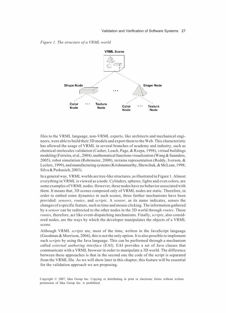
Validation and Verification of Software Systems 27
Copyright © 2007, Idea Group Inc. Copying or distributing in print or electronic forms without writtenpermission of Idea Group Inc. is prohibited.
files to the VRML language, non-VRML experts, like architects and mechanical engi-neers, were able to build their 3D models and export them to the Web. This characteristichas allowed the usage of VRML in several branches of academy and industry, such aschemical-molecules validation (Casher, Leach, Page, & Rzepa, 1998), virtual buildingsmodeling (Ferreira, et al., 2004), mathematical functions visualization (Wang & Saunders,2005), robot simulation (Rohrmeier, 2000), terrains representation (Reddy, Iverson, &Leclerc, 1999), and manufacturing systems (Krishnamurthy, Shewchuk, & McLean, 1998;Silva & Perkusich, 2003).In a general way, VRML worlds are tree-like structures, as illustrated in Figure 1. Almosteverything in VRML is viewed as a node. Cylinders, spheres, lights and even colors, aresome examples of VRML nodes. However, these nodes have no behavior associated withthem. It means that, 3D scenes composed only of VRML nodes are static. Therefore, inorder to embed some dynamics in such scenes, three further mechanisms have beenprovided: sensors, routes, and scripts. A sensor, as its name indicates, senses thechanges of a specific feature, such as time and mouse clicking. The information gatheredby a sensor can be redirected to the other nodes in the 3D world through routes. Theseroutes, therefore, act like event-dispatching mechanisms. Finally, scripts, also consid-ered nodes, are the ways by which the developer manipulates the objects of a VRMLscene.Although VRML scripts are, most of the time, written in the JavaScript language(Goodman & Morrison, 2004), this is not the only option. It is also possible to implementsuch scripts by using the Java language. This can be performed through a mechanismcalled external authoring interface (EAI). EAI provides a set of Java classes thatcommunicate with a VRML browser in order to manipulate a 3D world. The differencebetween these approaches is that in the second one the code of the script is separatedfrom the VRML file. As we will show later in this chapter, this feature will be essentialfor the validation approach we are proposing.
Figure 1. The structure of a VRML world

28 Almeida, Silva, Ferreira, Loureiro, & Perkusich
Copyright © 2007, Idea Group Inc. Copying or distributing in print or electronic forms without writtenpermission of Idea Group Inc. is prohibited.
The Java 3D3 (Selman, 2002) API is part of Sun’s JavaMedia suite and is devoted to theconstruction of Java applications and applets filled with 3D graphics. Like in VRML, Java3D scenes are structured in a tree-like way. Therefore, each object in a scene is viewedas node of the tree. Through Java 3D, it is possible to control the shape, color, andtransparency of objects. Furthermore, it allows the developer to define how such objectsmove, rotate, shrink, stretch, and morph as time goes by. Environmental manipulationsare also possible, by defining background images, lighting modes, and even fog effects.Internally, Java 3D uses the system native libraries, such as Direct3D and Open GL, tospeed up performance. It provides applications with three different rendering modes:immediate, retained, and compiled-retained. The basic difference between these modesis concerned with performance, where the immediate mode is the slowest one and thecompiled-retained is the fastest. Each of these modes has its own advantages, andtherefore, the choice of which mode to use will depend on the application.Extensible 3D graphics (X3D)4 is both a language, based on extensible markup language(XML), and a format for creating and interchanging 3D content. As the X3D is compatiblewith the VRML specification, X3D files can be modeled using either X3D or VRML syntax.Different from the previously presented technologies, X3D is embedded with the notionof profiles, each one providing a specific set of characteristics. The profiles are basedon a componentized architecture, allowing the insertion of new components to supportfeatures not provided by the profile. This allows the definition of profiles targeted tospecific fields, for example, medical and automobile visualizations.The structure of a virtual world in X3D is similar to that of Java 3D and VRML, that is,a tree-like model. From the functional perspective, X3D provides many of the functionalitiesof VRML and Java 3D, such as scripts, lighting, materials, and animations. However, aninteresting feature of X3D is the possibility of building virtual worlds by composingobjects entirely from other scenes or locations on the Web.
Validation and Verification Method
In the context of our method for software verification and validation, we have definedthree roles: CPN Developer, VRML Developer, and Final User. Based on these roles,some steps for verifying and validating the software have been defined. Figure 2illustrates such separation of roles in a macro view of our method.The CPN Developer knows how to model and verify the system according to itsrequirements using coloured Petri nets. The CPN Developer aims at proving that thespecification is correct. In case of modeling, he or she must identify the global systembehavior and model it using arcs, places, and transitions. In general, each transitionrepresents an occurrence of a system execution (e.g., an event, a process, etc.).Therefore, firing a transition or a set of transitions simulates a system behavior. Forexample, the firing of a transition named “input” may simulate the fact that the user inputsdata on the system. When verifying the system, the specification modeling is provedcorrect for all possible behaviors.

Validation and Verification of Software Systems 29
Copyright © 2007, Idea Group Inc. Copying or distributing in print or electronic forms without writtenpermission of Idea Group Inc. is prohibited.
The VRML Developer knows how to model and validate the system. However, unlike theCPN Developer, the VRML Developer aims at final user validation. For that, he or shemust model the system as simply as possible, yet still in accordance with the specifica-tion. The VRML modeling must be performed based on the events defined as transitionsby the CPN Developer. Thus, the VRML Developer is responsible for correlating CPNand VRML events.The Final User knows how the system works. He or she is responsible for specifyingthe system and validating if the system modeled is the one specified previously. For that,the Final User must describe the system requirements and visualize the VRML model indetermining if it covers the requirements.In what follows, we describe a set of steps for validating and verifying systems usingCPNs and VRML. Each step is related to a specific role. In Figure 3, the phases of themethod are depicted. A simple manufacturing system is used for illustrating the appli-cation of each phase (Silva & Perkusich, 2003).
System Specification (Final User)
The specification of the system is the first and main phase. Functional and nonfunctionalrequirements are described and, based on them, the modeling can be performed. Amanufacturing system is a system organized into cells. Each cell has one or more relatedmachines and a transport system. Two kinds of transport systems are considered: thoseinside cells and those outside cells. For simplicity, in this example the focus is onproduction and transport issues. In Figure 4, the architecture of the manufacturingsystem is illustrated.
Figure 2. Separation of roles
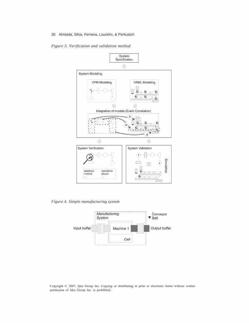
30 Almeida, Silva, Ferreira, Loureiro, & Perkusich
Copyright © 2007, Idea Group Inc. Copying or distributing in print or electronic forms without writtenpermission of Idea Group Inc. is prohibited.
Figure 3. Verification and validation method
Figure 4. Simple manufacturing system

Validation and Verification of Software Systems 31
Copyright © 2007, Idea Group Inc. Copying or distributing in print or electronic forms without writtenpermission of Idea Group Inc. is prohibited.
CPN Modeling (CPN Developer)
The system is modeled using hierarchical coloured Petri nets. The Design/CPN tools setshould be used in this phase. The result of this activity is a set of CPN models that canbe simulated and later verified. Figure 5 illustrates the CPN modeling for the manufactur-ing system, presenting the places and transitions that are used to model the systemspecification.
VRML Modeling (VRML Developer)
In the third phase, the system is modeled using VRML. Any VRML modeling tool canbe used to perform this activity. This modeling is usually simpler and friendlier than theCPN modeling, since the objective is to validate the system according to the user needs.Figure 6 illustrates the VRML modeling for the manufacturing system.
Integration of Models (VRML Developer)
The fourth step involves the correlation between the CPN and VRML events. The resultof this activity is a map structure that represents the integration of the CPN and VRMLmodels. For example, the event of firing a transition in the CPN model could represent aVRML event, such as a sphere moving. Figure 7 illustrates the correlation of events forthe manufacturing systems. The correlated events are named CO, IV, OCB, and OV.
Figure 5. CPN modeling for the manufacturing system

32 Almeida, Silva, Ferreira, Loureiro, & Perkusich
Copyright © 2007, Idea Group Inc. Copying or distributing in print or electronic forms without writtenpermission of Idea Group Inc. is prohibited.
Figure 6. VRML modeling for the manufacturing system
Figure 7. Correlating events for the manufacturing system models
After the system-modeling phases, the system can be verified and validated. Thegenerated models are used in the system-verification and the system-validation activi-ties. Such activities are described below.
System Verification (CPN Developer)
In the fifth phase, the system is verified through the CPN models created during the CPN-modeling phase. Such models are passed to Design/CPN tools, in order to verify thecorrectness of the system according to behavioral properties using verification tech-niques such as model checking. Modeling and verification guidelines for CPNs using theDesign/CPN tools and model checking can be found in Almeida et al. (2005).
InputBuffer
ManufacturingSystem
ConveyorBelt
OutputBuffer
Machine 1
Validation and Verification of Software Systems 33
Copyright © 2007, Idea Group Inc. Copying or distributing in print or electronic forms without writtenpermission of Idea Group Inc. is prohibited.
System Validation (Final User)
In the last step, the system is validated through both the CPN and VRML models. Asimulation of the system through the VRML models is performed based on the eventsgenerated by the simulation of the CPN models. Each event generated by the CPN modeland defined as a “mapped event” in the integration-of-models activity can change thestate of the VRML world. Thus, it is possible to visualize the behavior of the CPN-modelsimulation through the friendly VRML graphical animations.
A Software Platform forIntegrating VRML and CPN
In order to make the application of the steps for the validation and verification of softwaresystems easier, a software platform is described here.The CPN/VRML Software Platform manages the integration of VRML and CPN models.For that, the Design/CPN tool is used for CPN modeling and simulation, and a Java-compliant VRML browser is used for the model visualization. The architecture of thesoftware platform is presented in Figure 8, and the integration steps are described below,considering the event correlation performed in the integration-of-models phase.
1. The CPN Module is responsible for receiving event notifications from the Design/CPN simulation tools. During the simulation, each event is announced for the CPNModule. The communication is performed via sockets.
2. The CPN Module extracts the CPN model information using the Comms/CPN library(Gallasch & Kristensen, 2001) and forwards the event notifications to the mappingmodule.
3. The Mapping Module retrieves from the XML mapping files the VRML events thatare related to the CPN event.
4. The Mapping Module forwards the identification of the VRML events that shouldbe announced through a VRML-Java package.
5. Finally, the VRML Module updates the virtual world according to the CPNsimulation events, allowing a friendly visualization of the CPN model. The ExternalAuthoring Interface mechanism, described in the “Background” section, is usedto manipulate the VRML view.

34 Almeida, Silva, Ferreira, Loureiro, & Perkusich
Copyright © 2007, Idea Group Inc. Copying or distributing in print or electronic forms without writtenpermission of Idea Group Inc. is prohibited.
Case Study:A Component-Based EmbeddedAutomation and Control System
In this section the application of the proposed method and software platform forvalidating and verifying a component-based embedded automation and control systemis described.
System Specification
In Figure 9, the architecture of the embedded system, which is based on the frameworkstructure introduced in Perkusich, Almeida, and Araújo (2003) is illustrated.
Figure 8. Software-platform architecture
Figure 9. Architecture of the real-time embedded automation and control application
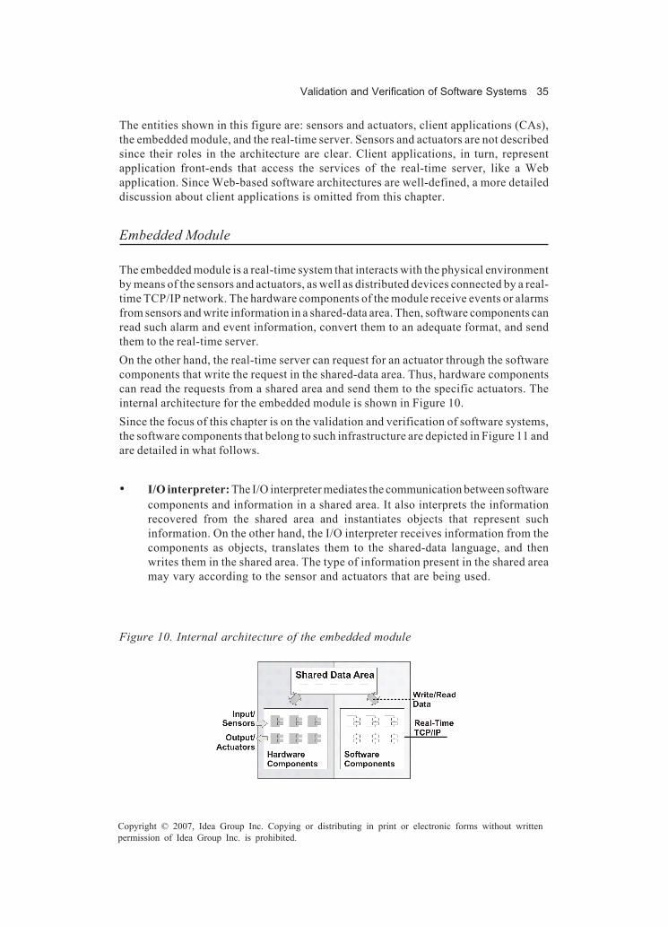
Validation and Verification of Software Systems 35
Copyright © 2007, Idea Group Inc. Copying or distributing in print or electronic forms without writtenpermission of Idea Group Inc. is prohibited.
The entities shown in this figure are: sensors and actuators, client applications (CAs),the embedded module, and the real-time server. Sensors and actuators are not describedsince their roles in the architecture are clear. Client applications, in turn, representapplication front-ends that access the services of the real-time server, like a Webapplication. Since Web-based software architectures are well-defined, a more detaileddiscussion about client applications is omitted from this chapter.
Embedded Module
The embedded module is a real-time system that interacts with the physical environmentby means of the sensors and actuators, as well as distributed devices connected by a real-time TCP/IP network. The hardware components of the module receive events or alarmsfrom sensors and write information in a shared-data area. Then, software components canread such alarm and event information, convert them to an adequate format, and sendthem to the real-time server.On the other hand, the real-time server can request for an actuator through the softwarecomponents that write the request in the shared-data area. Thus, hardware componentscan read the requests from a shared area and send them to the specific actuators. Theinternal architecture for the embedded module is shown in Figure 10.Since the focus of this chapter is on the validation and verification of software systems,the software components that belong to such infrastructure are depicted in Figure 11 andare detailed in what follows.
• I/O interpreter: The I/O interpreter mediates the communication between softwarecomponents and information in a shared area. It also interprets the informationrecovered from the shared area and instantiates objects that represent suchinformation. On the other hand, the I/O interpreter receives information from thecomponents as objects, translates them to the shared-data language, and thenwrites them in the shared area. The type of information present in the shared areamay vary according to the sensor and actuators that are being used.
Figure 10. Internal architecture of the embedded module

36 Almeida, Silva, Ferreira, Loureiro, & Perkusich
Copyright © 2007, Idea Group Inc. Copying or distributing in print or electronic forms without writtenpermission of Idea Group Inc. is prohibited.
• Data converter: The data converter implements data conversion specific algo-rithms defined by the application. The data are converted from the I/O interpreterlanguage to the specific application language. For example, when the I/O interpreterreturns an object with a binary content, the data converter may transform it into anobject with a decimal content, if this is the application format. The data conversionalso depends on the type of information.
• Synchronizer: The synchronizer implements the synchronous communicationamong the software components of the embedded module and the softwarecomponents of the real-time server. As said before, a real-time TCP/IP network isused. This component acts as a bridge between the two sides of the distributedapplication, and all the requests, or the response for the requests, issued betweenthe real-time server and the embedded module occur through this component.
• Device controller: The device controller implements the initialization, tests, andliberation of devices connected to the interfaces of the embedded module. Suchservices are executed based on the requests submitted by the Device Controllerto the shared area through the interpreter.
Real-Time Server
The real-time server can be a personal or industrial computer that manages the network.It runs the Linux/RT real-time operating system (Abbott, 2003). The internal architectureof the real-time server is shown in Figure 12. The software components that belong tothe real-time-server infrastructure are briefly described as follows.
• Synchronizer: The synchronizer implements the communication on the real-time-server side. The implementation is similar to the embedded-module synchronizer.
• Data controller: The data controller provides data-flow control for the system (i.e.,read, write, and parameter forwarding) based on the implementation of the servicesthat are made available by the UI Module.
Figure 11. Software components infrastructure for the embedded module

Validation and Verification of Software Systems 37
Copyright © 2007, Idea Group Inc. Copying or distributing in print or electronic forms without writtenpermission of Idea Group Inc. is prohibited.
• UI module: The user-interface module provides an interface for the servicesimplemented by the software components, so that they can be used by theapplication connected to the Internet.
CPN Modeling
In Figure 13, the CPN model for the embedded module is shown. The places, arcs, andtransitions that model the I/O-interpreter, Data-converter, Synchronizer, and Device-controller modules are depicted in this figure. The complete description of the CPNmodeling for this case study is presented in Silva and Perkusich (2005).
VRML Modeling
Figure 14 illustrates the VRML modeling of the real-time embedded automation andcontrol application. The software components detailed earlier and the communicationamong them have been modeled using VRML nodes. Box nodes, with their namesmodeled with Text nodes, represent the software components; whereas Cylinder nodesrepresent the communication among the components.The “System Validation” section will detail how the dynamic features (i.e., data exchangeamong the components and data processing) of the system are simulated in VRML.
Integration of Models
Some VRML events have been created in order to allow the integration between the CPNand VRML models. Such events are implemented in JavaScript and they are grouped into
Figure 12. Software components infrastructure for the real-time server

38 Almeida, Silva, Ferreira, Loureiro, & Perkusich
Copyright © 2007, Idea Group Inc. Copying or distributing in print or electronic forms without writtenpermission of Idea Group Inc. is prohibited.
Figure 13. CPN modeling for the embedded module
a Script node through VRML input events. In Listing 1, the JavaScript function thatimplements the VRML-event behavior correlated to the CPN transition UIModule ispresented. Such an event simulates the data exchange between the Data Controller andthe UI Module of the Real-time Server.The rtsDataControllerToUIModule function forwards the received event value to theinput event communicateForward of the Cylinder situated between the Data Control-ler and the UI Module. Besides, this function also forwards the value true to the inputevent showDataExchange of the UI Module.
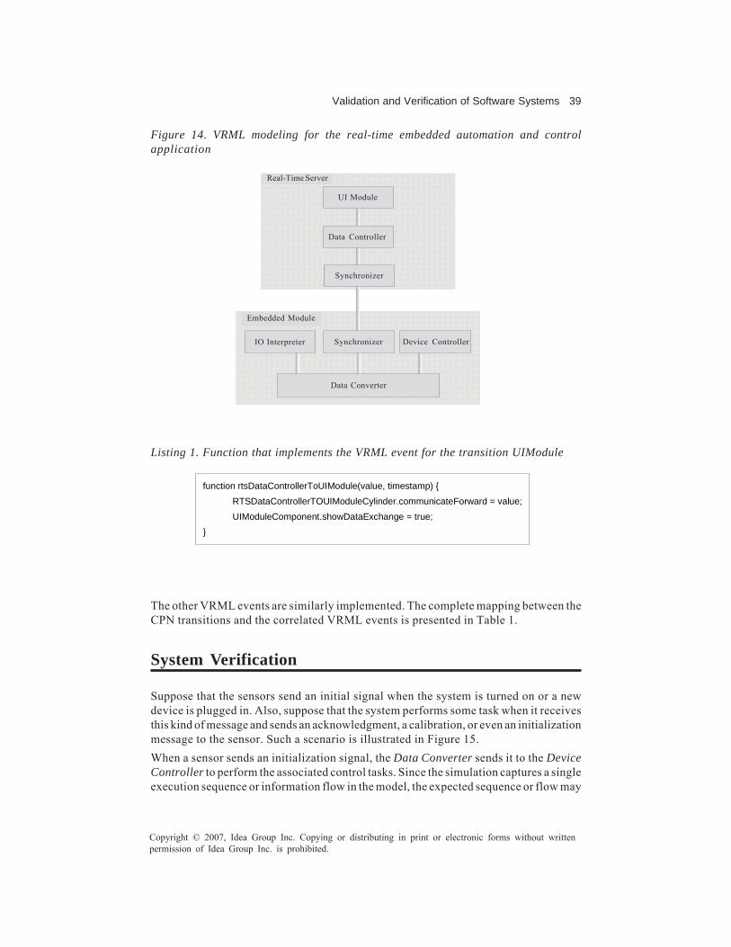
Validation and Verification of Software Systems 39
Copyright © 2007, Idea Group Inc. Copying or distributing in print or electronic forms without writtenpermission of Idea Group Inc. is prohibited.
The other VRML events are similarly implemented. The complete mapping between theCPN transitions and the correlated VRML events is presented in Table 1.
System Verification
Suppose that the sensors send an initial signal when the system is turned on or a newdevice is plugged in. Also, suppose that the system performs some task when it receivesthis kind of message and sends an acknowledgment, a calibration, or even an initializationmessage to the sensor. Such a scenario is illustrated in Figure 15.When a sensor sends an initialization signal, the Data Converter sends it to the DeviceController to perform the associated control tasks. Since the simulation captures a singleexecution sequence or information flow in the model, the expected sequence or flow may
Figure 14. VRML modeling for the real-time embedded automation and controlapplication
Listing 1. Function that implements the VRML event for the transition UIModule
function rtsDataControllerToUIModule(value, timestamp) { RTSDataControllerTOUIModuleCylinder.communicateForward = value; UIModuleComponent.showDataExchange = true;
}
Data Converter
IO Interpreter Synchronizer Device Controller
Embedded Module
UI Module
Data Controller
Synchronizer
Real-Time Server

40 Almeida, Silva, Ferreira, Loureiro, & Perkusich
Copyright © 2007, Idea Group Inc. Copying or distributing in print or electronic forms without writtenpermission of Idea Group Inc. is prohibited.
Table 1. Mapping between the CPN transitions and the correlated VRML events
CPN transition VRML event ToUiMod rtsDataControllerToUIModule UIModule rtsUIModuleProcessing BackToDCon rtsUIModuleToDataController DataControl rtsDataControlProcessing TORTSyncB rtsDataControllerToSynchronizer SyncOutRT rtsSynchronizerProcessing DConToIOInt emDataConverterToIOInterpreter IOIntToDCon emIOInterpreterToDataConverter DataConvert emDataConverterProcessing DConToDevC emDataConverterToDeviceController DevCToDCon emDeviceControllerToDataConverter DevController emDeviceControllerProcessing SyncToDConv emSynchronizerToDataConverter DConvToSync emDataConverterToSynchronizer IOInterpreter emIOInterpreterProcessing
have been violated. Thus, we must verify the scenario for all possible situations basedon model checking (Clarke, Emerson, & Sistla, 1986) to guarantee that the expected flowhas always been satisfied. For that, the desired system properties should be describedin a propositional temporal logic such as computation tree logic (CTL) (Clarke et al.). Itssemantic is defined with respect to paths in a Kripke structure. A path on such a structureis an infinite sequence of states (s0; s1; …) such that si+1 is reached from si for all i ≥ 0.The CTL formula AGϕ means that for all paths starting from s0, ϕ holds at every state alongthose paths. In other words, ϕ holds globally. The CTL formula AFϕ means that for allpaths starting from s0, ϕ holds at some state along the path. In other words, ϕ is inevitable.Considering the scenario shown in Figure 15, we must prove that when some devicesends an initialization message, the flow will be through the device controller. To provethis scenario, two atomic propositions PA and PB are used. The proposition PA is trueif there is a token in place IODConIn, illustrated in Figure 13. The proposition PB is trueif there is a token in place DConOutDevC, also illustrated in Figure 13. The CTL formulato prove this scenario is shown below:
AG ( PA → AF ( PB ) )
Therefore, the formula is true if PA is true and PB is true in the future. It means that if thereis a token in the data converter input, this token is sent to device controller input, whichis the component that implements control tasks such as initialization, calibration, and
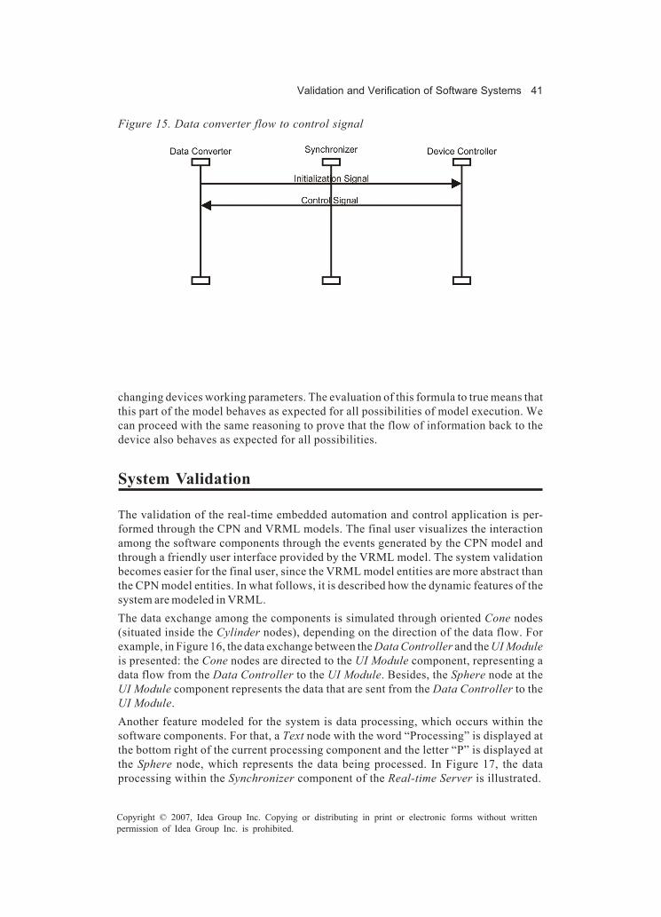
Validation and Verification of Software Systems 41
Copyright © 2007, Idea Group Inc. Copying or distributing in print or electronic forms without writtenpermission of Idea Group Inc. is prohibited.
changing devices working parameters. The evaluation of this formula to true means thatthis part of the model behaves as expected for all possibilities of model execution. Wecan proceed with the same reasoning to prove that the flow of information back to thedevice also behaves as expected for all possibilities.
System Validation
The validation of the real-time embedded automation and control application is per-formed through the CPN and VRML models. The final user visualizes the interactionamong the software components through the events generated by the CPN model andthrough a friendly user interface provided by the VRML model. The system validationbecomes easier for the final user, since the VRML model entities are more abstract thanthe CPN model entities. In what follows, it is described how the dynamic features of thesystem are modeled in VRML.The data exchange among the components is simulated through oriented Cone nodes(situated inside the Cylinder nodes), depending on the direction of the data flow. Forexample, in Figure 16, the data exchange between the Data Controller and the UI Moduleis presented: the Cone nodes are directed to the UI Module component, representing adata flow from the Data Controller to the UI Module. Besides, the Sphere node at theUI Module component represents the data that are sent from the Data Controller to theUI Module.Another feature modeled for the system is data processing, which occurs within thesoftware components. For that, a Text node with the word “Processing” is displayed atthe bottom right of the current processing component and the letter “P” is displayed atthe Sphere node, which represents the data being processed. In Figure 17, the dataprocessing within the Synchronizer component of the Real-time Server is illustrated.
Figure 15. Data converter flow to control signal
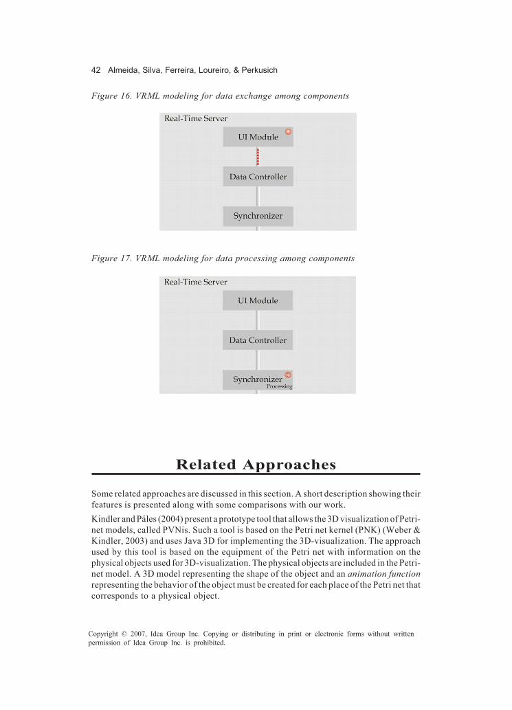
42 Almeida, Silva, Ferreira, Loureiro, & Perkusich
Copyright © 2007, Idea Group Inc. Copying or distributing in print or electronic forms without writtenpermission of Idea Group Inc. is prohibited.
Related Approaches
Some related approaches are discussed in this section. A short description showing theirfeatures is presented along with some comparisons with our work.Kindler and Páles (2004) present a prototype tool that allows the 3D visualization of Petri-net models, called PVNis. Such a tool is based on the Petri net kernel (PNK) (Weber &Kindler, 2003) and uses Java 3D for implementing the 3D-visualization. The approachused by this tool is based on the equipment of the Petri net with information on thephysical objects used for 3D-visualization. The physical objects are included in the Petri-net model. A 3D model representing the shape of the object and an animation functionrepresenting the behavior of the object must be created for each place of the Petri net thatcorresponds to a physical object.
Figure 16. VRML modeling for data exchange among components
Figure 17. VRML modeling for data processing among components

Validation and Verification of Software Systems 43
Copyright © 2007, Idea Group Inc. Copying or distributing in print or electronic forms without writtenpermission of Idea Group Inc. is prohibited.
There is no method for validation and verification associated with this tool. Its purposeis only to provide the visualization of Petri net models in a 3D way. Therefore, there isalso no effort to integrate the validation process through the 3D-visualization, with theverification process, or through the Petri net model. Such activities are realized sepa-rately.Bardohl, Ermel, and Ribeiro (2000) introduce ideas towards visual specification andanimation of Petri net-based models. In this work, the animation of algebraic high-level(AHL) nets (Padberg, Ehrig, & Ribeiro, 1995), which are a combination of place-transitionnets and algebraic specifications (Ehrig & Mahr, 1985), is described. For that theanimation, transformation rules are applied to the behavior rules (semantically equivalentto the transitions of the net) of an AHL net model, generating an animation view from themodel. Such a view allows the visualization of the behavior of the system in a domain-specific layout.In a Petri net Editor,the user defines the transformation rules from the Petri-net view tothe animation view. In this way, there is no separation of the roles concerned with theuse of this approach. Either the user that knows Petri nets must know the visual-modelinglanguage or the visual modeler must know Petri nets. Finally, it seems the visual-modelinglanguage is not as full-featured as VRML.
Conclusion and Future Trends
This chapter describes a method for the verification and validation of software systemsusing coloured Petri nets (CPN) and VRML. The method is defined over three separatedroles: the CPN Developer, responsible for CPN issues; the VRML Developer, respon-sible for VRML issues; and the Final User, responsible for specifying and validating thesystem.According to the proposed method, the system is modeled using CPN and VRML basedon its requirements. Next, the CPN and VRML events are correlated in order to allow theCPN model simulation to control the VRML model simulation. For that, we propose asoftware tool that is used to correlate CPN and VRML events.We describe the method as a set of phases for modeling and verification. The applicationof each phase is illustrated using a flexible manufacturing-system example. This makesit easier to understand the implementation of our method. As a real case study, wedescribed the validation and verification of an embedded software system using theproposed method and platform.The main future trend in the context of software verification and validation related to ourwork is to provide mechanisms for reducing the gap between validation and verificationtechniques. In this chapter, we propose a method and a tool that reduce such a gap,promoting the integration between VRML and CPN developers, still obtaining softwareverification and friendly software validation.However, for some domains, the integration can be improved. For example, a VRML-component library for a specific domain may be created. Thus, when verifying and

44 Almeida, Silva, Ferreira, Loureiro, & Perkusich
Copyright © 2007, Idea Group Inc. Copying or distributing in print or electronic forms without writtenpermission of Idea Group Inc. is prohibited.
validating software for such domain, the integration tool could generate the VRML modelbased on the name of the component events. This automatic approach would reduce theeffort on mapping CPN events to VRML ones.On the other hand, verification tools could be improved in order to provide friendlymechanisms for visualizing what is being verified. It will be very important to the large-scale use of verification techniques in the context of industrial software engineering.In this future, we plan to apply our method for validating and verifying software in otherdomains, focusing on complex interaction-centric ones (e.g., multiagent systems, as inWeiss, 2000, and workflow management systems, as in van der Aalst & van Hee, 2002).The validation of these systems through VRML may be primordial.
References
Abbott, D. (2003). Linux for embedded and real-time applications. Oxford, UK: Newnes.Almeida, H., Silva, L., Perkusich, A., & Costa, E. (2005). A formal approach for the
modelling and verification of multiagent plans based on model checking and Petrinets. In R. Choren, A. Garcia, C. Lucena, & A. Romanovsky (Eds.), Softwareengineering for multi-agent systems III: Research issues and practical applica-tions (Vol. 3390, pp. 162-179). Berlin, Germany: Springer-Verlag.
Bardohl, R., Ermel, C., & Ribeiro, L. (2000). Towards visual specification and animationof Petri net based models. In Proceedings of the Workshop on Graph Transforma-tion Systems (GRATRA ’00) (pp. 22-31). Berlin, Germany.
Casher, O., Leach, C., Page, C. S., & Rzepa, H. S. (1998). Virtual reality modelling language(VRML) in chemistry. Chemistry in Britain, 34(9), 26.
Christensen, S., & Jepsen, L. O. (1991, June 17-19). Modelling and simulation of a networkmanagement system using hierarchical coloured Petri nets. In E. Moseklide (Ed.),Modelling and Simulation, 1991: Proceedings of the 1991 European SimulationMulticonference, the Panum Institute Copenhagen, Denmark. San Diego, CA:Society for Computer Simulation International.
Christensen, S., & Mortensen, K. H. (1996). Design/CPN ASK-CTL manual. Denmark:University of Aarhus.
Clarke, E. M., Emerson, E. A., & Sistla, A. P. (1986). Automatic verification of finite-stateconcurrent systems using temporal logic specifications. ACM Transactions onProgramming Languages and Systems, 2(8), 244-263.
Ehrig, H., & Mahr, B. (1985). Fundamentals of algebraic specification 1: Equations andinitial semantics. Berlin, Germany: Springer-Verlag.
Ferreira, G. V., Loureiro, E. C., Nogueira, W. A., Gomes, A. A., Almeida, H. O., & Frery,A. (2004). Uma abordagem baseada em componentes para a construção de edifíciosvirtuais (in Portuguese). In Proceedings of VII Symposium on Virtual Reality-SVR2004 (Vol. 7, pp. 279-290). Porto Alegre, Brazil: Sociedade Brasileira de Computação.
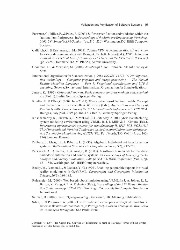
Validation and Verification of Software Systems 45
Copyright © 2007, Idea Group Inc. Copying or distributing in print or electronic forms without writtenpermission of Idea Group Inc. is prohibited.
Fuhrman, C., Djlive, F., & Palza, E. (2003). Software verification and validation within the(rational) unified process. In Proceedings of the Software Engineering Workshop,2003, 28th Annual NASA Goddard (pp. 216 - 220). Washington, DC: IEEE ComputerSociety.
Gallasch, G., & Kristensen, L. M. (2001). Comms/CPN: A communication infrastructurefor external communication with Design/CPN. In K. Jensen (Ed.), 3rd Workshop andTutorial on Practical Use of Coloured Petri Nets and the CPN Tools (CPN’01)(pp. 75-90). Denmark: DAIMI PB-554, Aarhus University.
Goodman, D., & Morrison, M. (2004). JavaScript bible. Hoboken, NJ: John Wiley &Sons.
International Organization for Standardization. (1998). ISO/IEC 14772-1:1998: Informa-tion technology — Computer graphics and image processing — The VirtualReality Modeling Language — Part 1: Functional specification and UTF-8encoding. Geneva, Switzerland: International Organization for Standardization.
Jensen, K. (1992). Coloured Petri nets. Basic concepts, analysis methods and practicaluse (Vol. 1). Berlin, Germany: Springer-Verlag.
Kindler, E., & Páles, C. (2004, June 21-25). 3D-visualization of Petri net models: Conceptand realization. In J. Cortadella & W. Reisig (Eds.), Applications and Theory ofPetri Nets 2004: Proceedings of the 25th International Conference, ICATPN 2004,Bologna, Italy (Vol. 3099, pp. 464-473). Berlin, Germany: Springer-Verlag.
Krishnamurthy, K., Shewchuk, J., & McLean, C. (1998, May 18-20). Hybrid manufacturingsystem modeling environment using VRML. In J. J. Mills & F. Kimura (Eds.),Information infrastructure systems for manufacturing II, IFIP TC5 WG5.3/5.7Third International Working Conference on the Design of Information Infrastruc-ture Systems for Manufacturing (DIISM ’98), Fort Worth, TX (Vol. 144, pp. 163-174). London: Kluwer.
Padberg, J., Ehrig, H., & Ribeiro, L. (1995). Algebraic high-level net transformationsystems. Mathematical Structures in Computer Science, 5(2), 217-256.
Perkusich, A., Almeida, H., & Araújo, D. (2003). A software framework for real-timeembedded automation and control systems. In Proceedings of Emerging Tech-nologies and Factory Automation, 2003 (ETFA ’03) IEEE Conference (Vol. 2, pp.181-184). Washington, DC: IEEE Computer Society.
Reddy, M., Iverson, L., & Leclerc, Y. G. (1999). Enabling geographic support in virtualreality modeling with GeoVRML. Cartography and Geographic InformationScience, 26(3), 180-182.
Rohrmeier, M. (2000). Web based robot simulation using VRML. In J. A. Joines, R. R.Barton, K. Kang, & P. A. Fishwick (Eds.), Proceedings of the 32nd Winter Simula-tion Conference (pp. 1525-1528). San Diego, CA: Society for Computer SimulationInternational.
Selman, D. (2002). Java 3D programming. Greenwich, UK: Manning Publications.Silva, L., & Perkusich, A. (2003). Uso de realidade virtual para validação de modelos de
sistemas flexíveis de manufatura (in Portuguese). Anais do VI Simpósio Brasileirode Automação Inteligente. São Paulo, Brazil.

46 Almeida, Silva, Ferreira, Loureiro, & Perkusich
Copyright © 2007, Idea Group Inc. Copying or distributing in print or electronic forms without writtenpermission of Idea Group Inc. is prohibited.
Silva, L., & Perkusich, A. (2005). A model-based approach to formal specification andverification of embedded systems using coloured Petri nets. In C. Atkinson,C. Bunse, H. G. Gross, & C. Peper (Eds.), Component-based software developmentfor embedded systems (vol. 3778, pp. 35-58). Berlin, Germany: Springer-Verlag.
van der Aalst, W., & van Hee, K. (2002). Workflow management: Models, methods, andsystems: Cooperative information systems. Cambridge, MA: MIT Press.
Wang, J. (1998). Timed Petri nets: Theory and applications. London: Kluwer Academic.Wang, Q., & Saunders, B. (2005). Web-based 3D visualization in a digital library of
mathematical functions. In Proceedings of the Tenth International Conference on3D Web Technology (pp. 151-157). New York: ACM Press.
Weber, M., & Kindler, E. (2003). The Petri net kernel. In H. Ehrig, W. Reisig, G. Rozenberg,& H. Weber (Eds.), Petri net technology for communication-based systems:Advances in Petri nets (Vol. 2472, pp. 109-124). Berlin, Germany: Springer-Verlag.
Weiss, G. (Ed.). (2000). Multiagent systems — A modern approach to distributedartificial intelligence. Cambridge, MA: MIT Press.
Zaslavsky, A., Yeo, L., Lai, S., & Mitelman, B. (1995). Petri nets analysis of transactionand submitter management protocols in mobile distributed computing environ-ment. In Proceedings of the 4th International Conference on Computer Commu-nications and Networks (ICCCN ’95) (pp. 292-299). Washington, DC: IEEEComputer Society.
Endnotes
1 Design/CPN can be downloaded at http://www.daimi.au.dk/designCPN/2 VRML resources such as editors and browsers are available at http://
www.vrmlsite.com/3 The official site of Java 3D is available at https://java3d.dev.java.net4 The official site of X3D is available at http://www.web3d.org

Method for Evaluating User Interfaces 47
Copyright © 2007, Idea Group Inc. Copying or distributing in print or electronic forms without writtenpermission of Idea Group Inc. is prohibited.
Chapter III
Integrating Usability,Semiotic, and Software
Engineering into aMethod for Evaluating
User InterfacesKenia Sousa, University of Fortaleza, Brazil
Albert Schilling, University of Fortaleza, Brazil
Elizabeth Furtado, University of Fortaleza, Brazil
Abstract
We present artifacts and techniques used for user interface (UI) design and evaluation,performed by professionals from the human-computer interaction (HCI) area of study,covering usability engineering and semiotic engineering, which can assist softwareengineering (SE) to perform usability tests starting earlier in the process. Tests ofvarious interaction alternatives, produced from these artifacts, are useful to verify ifthese alternatives are in accordance with users’ preferences and constraints, andusability patterns, and can enhance the probability of achieving a more usable andreliable product.

48 Sousa, Schilling, & Furtado
Copyright © 2007, Idea Group Inc. Copying or distributing in print or electronic forms without writtenpermission of Idea Group Inc. is prohibited.
Introduction
In a software development process (SDP), it is crucial for developers, customers, andusers to interact in order to specify, generate, and evaluate the software. From softwarespecification to its delivery, various kinds of tests must be performed, involving aspectssuch as: functionality, portability, performance, and usability. This work focuses on thecontext of usability, communicability, and functionality tests (e.g., appropriateness ofa chosen interface design alternative to user preferences, consistency to a visual pattern,efficient execution of interactive tasks on interface objects, etc.).Through our researches on tests in HCI and SE, and through our experiments on theirintegration in a SDP, we verified that HCI concepts facilitate the UI evaluation workperformed by the test team of an interactive system under development. More specifi-cally, by means of UI generation based on HCI models (e.g., task model), it is possibleto evaluate the UI earlier (e.g., its functionality), independent of having the entirenoninteractive specification ready. Prototypes, for instance, can represent UI designalternatives that may be tested early by HCI experts to verify if they are in accordancewith user preferences, usability patterns, and so on.This work presents a SDP to design and evaluate UIs, based on the integration ofconcepts, models, and activities of usability, semiotic, and software engineering.This chapter is structured as follows: The “User-Interface Evaluation” section shows thecontribution of each engineering area to UI evaluation; “The Process” section describesthe UI design process; “The Evaluation Strategy” section describes the UI evaluationprocess, showing which concepts are used to perform tests and when they are performed;the “Case Study” section describes the case study in which we designed and evaluatedUIs for the Brazilian System for the Digital Television (SBTVD); and, finally, the“Findings and Future Works” section describes findings and future works, and the“Conclusion” section concludes this work.
User-Interface Evaluation
In this section, we present concepts and evaluation techniques from usability engineer-ing, software engineering, and semiotic engineering.
Usability Engineering
Usability engineering is a set of activities that ideally take place throughout the lifecycleof the product, with significant activity at the early stages even before the UI has beendesigned. The need to have multiple usability engineering stages supplementing eachother was recognized early in the field, though not always followed in developmentprojects (Gould & Lewis, 1985).

Method for Evaluating User Interfaces 49
Copyright © 2007, Idea Group Inc. Copying or distributing in print or electronic forms without writtenpermission of Idea Group Inc. is prohibited.
In usability engineering, techniques and methods are defined aiming to assure a highusability level of the interactive UIs. Among them, we emphasize the application ofergonomic criteria in the UI design. Verification of these criteria in designed UIs is calledheuristic evaluation, performed by usability experts without user participation. Evalua-tors examine the IS searching for problems that violate general principles of good UIdesign, diagnosing problems, obstacles or barriers that users will probably encounterduring their interaction. In addition, methods to capture usability requirements attendto user preferences, restrictions, and use-context. A usability requirement can be derivedfrom an interaction restriction; such as if part of the system needs to be implemented forpalm-top devices.The evaluation approaches from usability engineering suggests a structured sequenceof evaluations based on “usability inspections methods” and on “usability tests”.Some inspection methods are: (1) heuristic evaluation, verification of usability heuristics(Nielsen, 1993); (2) review of guidelines, verification if the UI is according to a list ofusability guidelines (Baranauskas & Rocha, 2003); (3) consistency inspection, verifica-tion of the consistency among the UIs related to terminology, color, layout, input andoutput format, and so on; and (4) cognitive walkthrough, simulation of the user “walking”through the UI to execute typical tasks.Some usability test methods are: (1) thinking out loud, we request the user to verbalizeeverything he or she thinks while using the system, and we expect that their thoughtsdemonstrate how the user interprets each UI item (Lewis, 1982); and (2) performancemeasures, quantification of some evaluated items to make future comparisons.
Software Engineering
Software engineering is composed of technologies and practices that are used in thedevelopment of software products, enhancing software productivity and quality, byproviding a more systematic and controlled SDP (Sommerville, 2001).In software engineering, there are various types of tests to be performed in each teststage, such as: usability tests to ensure that access and navigation through functionalitiesare appropriate for users; UI tests, to ensure a good functionality of the UI componentsand verify conformity to corporate patterns; and functionality tests, which are respon-sible for verifying if the generated software achieves all the proposed functionalitiesaccording to the customer’s requests. Test cases (Myers, 2004) are normally generatedand comprise procedures to be followed in test activities in order to deal with all possiblesituations when using the software, including basic flows, as well as error treatment andinvalid data verification.According to Pressman (1995), the main goal of test cases is to derive a set of tests thatwill probably reveal errors in the software. To achieve this goal, software engineeringbasically proposes two test categories: white-box and black-box tests.For Pressman (1995), the white=box test must verify the internal part of the product, testscan be performed to guarantee that the components are integrated, and the internaloperation achieves the performance level as specified in the requirements.
50 Sousa, Schilling, & Furtado
Copyright © 2007, Idea Group Inc. Copying or distributing in print or electronic forms without writtenpermission of Idea Group Inc. is prohibited.
Functional tests, or black box tests, represent a test approach in which tests are derivedfrom specifications of the system. In this kind of test, the evaluator is concerned with thefunctionality, not with the software implementation (Sommerville, 2001).In these two test categories, software engineering defines four main types of tests: unittests that are generally white-box tests; acceptance and regression tests that are usuallyblack-box tests, and integration tests that blend this two categories.
Semiotic Engineering
Semiotic engineering is an HCI theory that emphasizes aspects related to themetacommunication designer user(s) via user-system communication, which passesthrough the UIs of interactive applications. The system is considered to be the “deputy”or a representative of the system designer (Souza, Barbosa, & Silva, 2001). The contentof messages is the application usability model. Its expression is formed by the set of allinteraction messages sent through the UI during the interaction process. The user playsa double role: interacting with the system and interpreting messages sent by the designer.Semiotic engineering is essentially involved in test procedures with final users (empiricevaluation), aiming at system communicability analysis — based on qualitative evalu-ation, in which there are four phases: test preparation; labeling; interpretation, andformatting — and elaboration of the semiotic profile of the application to be evaluated.The techniques used in theses phases are: system-user observations, questionnaires,(somative-evaluation) inspections, interviews, filming,and so on.Semiotic engineering is essentially present in tests with final users (e.g., empiricevaluation), aiming at analyzing the system communicability. A UI has a good level ofcommunicability when it is able to successfully transmit the designer message to the user,allowing him or her to understand the system goal, the advantages of using it, how itworks, and the basic UI interaction principles.
Evaluation
After studying about evaluation techniques, artifacts and approaches from software,usability, and semiotic engineering we are able to conclude that an evaluation processcan be seen under various perspectives.Concerning software engineering, we noticed the importance of software quality con-cerning functionality, performance, portability, and other nonfunctional requirements.Its artifacts and techniques include the evaluation of these aspects in an objectivemanner.Usability engineering focuses in providing more ease of use, ease of learning, andefficiency to interactive systems.Semiotic engineering includes procedures that allow the evaluation of the quality of theinteractivity of systems by observing the communication through messages of the userto the system.
Method for Evaluating User Interfaces 51
Copyright © 2007, Idea Group Inc. Copying or distributing in print or electronic forms without writtenpermission of Idea Group Inc. is prohibited.
Based on these perspectives, we believe that an approach for UI evaluation of interactivesystems that integrates these approaches is able to guarantee a system with qualityconcerning functionality, usability, and interactivity, derived from software, usability,and semiotic engineering, respectively.Next, we will describe a lightweight development process for interactive systems, calledUPi (Sousa & Furtado, 2004), which integrates HCI and SE activities, artifacts, andprofessionals.
The Process
UPi can serve as a guide, providing useful steps and artifacts that can be tailored andcustomized when organizations intend to develop usable interactive systems. One of thebest advantages of UPi is the idea to focus on activities, artifacts and guidelines that addvalue to the UI generation. With this approach, it can be integrated with any other processand inherit activities that are vital to the entire process, but that are better defined andsolidified in other processes. For instance, project management, configuration andchange management, implementation, and deployment activities are very well detailedin the RUP (Kruchten, Ahlqvist, & Bylund, 2001). Besides the RUP, UPi can also beapplied in conjunction with ISO 13407 (ISO 13407, 1999), which already has otheractivities defined and validated, such as project planning, testing, and so on.UPi is composed of activities that aim at designing UIs. These activities are based on RUPactivities, but they follow different guidelines that take into consideration usabilityaspects.In this work, we are integrating UPi with UPi-Test (to be presented in the next section)in order to guide professionals that are developing interactive systems to evaluate themthroughout the entire development process.
Phase I: Inception
The main goal in this phase is to elicit requirements from users in order to develop aninteractive system that best suits their needs through the execution of some activities(presented as follows). These requirements are documented through certain artifacts:use-case models, task models, usability requirements, and paper sketches.Use-case models represent a well-established manner to define the system functionality,while task models can be used to detail use cases by breaking them down into tasks.Usability requirements represent users’ preferences or constraints that can be part ofa usable interactive system. Paper sketches focus on the interaction, UI components, andon the overall system structure, keeping the style guide secondary, without being tooabstract.The purpose of the Elicit Stakeholder Needs activity is to understand users, theirpersonal characteristics, and information on the environment where they are located that
52 Sousa, Schilling, & Furtado
Copyright © 2007, Idea Group Inc. Copying or distributing in print or electronic forms without writtenpermission of Idea Group Inc. is prohibited.
have a direct influence on the system definition, and to collect special nonfunctionalrequirements that the system must fulfill, such as performance, cost, and device requests.The purpose of the Find Actors and Use Cases and Structure the Use-case Modelactivities is to define the actors (users or other systems) that will interact with the systemand the functionality of the system that directly attend to users’ needs and support theexecution of their work productively.The purpose of the Detail a Use Case activity is to describe the use case’s tasks usingthe task model, to describe any usability requirements related to the use case, to definethe system navigation based on the task model hierarchical structure, and to create papersketches.The purpose of the Review Requirements activity is to verify, with usability experts, ifthe paper sketches are in accordance to the task model and validate, with users, if therequirements are in conformance with their needs by showing them the elaborated papersketches.
Phase II: Elaboration
The main goal in this phase is to transform the requirements in a representation that canbe understood by UI designers and programmers. These representations are providedby the following artifacts: system architecture, UI Definition Plan, and drawing proto-types.System Architecture is composed of smaller components that represent the mainfunctionality of the entire system. The UI Definition Plan is a new artifact that aims todefine which visual objects should be part of the UI. Drawing prototypes produce anaccurate image of the system and they are useful to demonstrate patterns and styleguides.The purpose of the Define and Refine the Architecture activity is to (re)design theclasses that represent the data that are handled by users while performing certain tasks.The purpose of the Define UI Plan activity is to define which visual objects and whichusability patterns can be part of the UI according to the nonfunctional requirementsdefined in the Elicit Stakeholder Needs activity.The purpose of the UI Prototyping activity is to design a UI prototype in drawingsfollowing the description specified in the task models, in the UI definition plan and in thesystem architecture.The purpose of the Evaluate Prototype activity is to verify if the UI prototypes are inaccordance to usability principles and to validate with users if the UI prototypes are inconformance with their needs.
Phase III: Construction
The main goal of this phase is to implement and verify the accuracy of the componentsimplemented and of the UI designed.

Method for Evaluating User Interfaces 53
Copyright © 2007, Idea Group Inc. Copying or distributing in print or electronic forms without writtenpermission of Idea Group Inc. is prohibited.
The purpose of the Implement Components activity is to develop the classes previouslydesigned and implement the UI prototyped.The purpose of the Evaluate the Version of the System activity is to verify if thefunctionality of the interactive system is in accordance with users’ requirements.
Phase IV: Transition
The main goal of this phase is to deliver to the customer a system with high level of qualityand usability.The purpose of the Deploy the System activity is to make the system available for thecustomer.The purpose of the Evaluate the System activity is to validate with users (by using thesystem in the deployment site) if the system conforms with their view of the system.All of these phases are supported by processes concerning configuration and changemanagement and project management, such as the RUP. This support is provided for theManage Change Requests activity, which aims at evaluating the impact of changerequests, deciding if they are to be included in the current iteration, and, if they areaccepted, manage the changes in the appropriate artifacts.Concerning the evaluation activities performed in each phase, they will be more thor-oughly explained in the next section.
The Evaluation Strategy
The unified process for evaluating interactive systems “UPi-Test” (Schilling et al., 2005)has the same phases as the RUP (inception, elaboration, construction, and transition)(Kruchten, Ahlqvist, & Bylund, 2001). This process is based on the Unified Process forInteractive Systems, called UPi (Sousa & Furtado, 2004) and follows the approach todesign UI prototypes dependent on the device (Coyette, Faulkner, Kolp, Limbourg, &Vanderdonckt, 2004).Each phase is directly related to a specific area. This way, usability engineering supportsthe verification and validation in the inception and elaboration phases, softwareengineering supports verification in the construction phase, and semiotic engineeringsupports validation in the transition phase.Figure 1 illustrates these four phases in the UPi-Test, each one with its flow of activities,artifacts, and techniques.UPi-Test includes the verification and validation of usability and functionality ofinteractive systems UIs. Nonfunctional requirements are not in the scope of this work,such as aspects related to database (e.g., connection, integrity, etc.), security, andarchitecture. These aspects can be supported in future versions of this process.
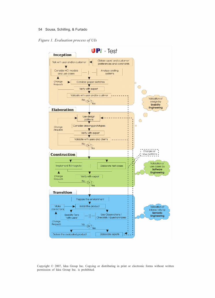
54 Sousa, Schilling, & Furtado
Copyright © 2007, Idea Group Inc. Copying or distributing in print or electronic forms without writtenpermission of Idea Group Inc. is prohibited.
Figure 1. Evaluation process of UIs
Method for Evaluating User Interfaces 55
Copyright © 2007, Idea Group Inc. Copying or distributing in print or electronic forms without writtenpermission of Idea Group Inc. is prohibited.
Phase I: Inception
The inception phase is important in guaranteeing that the following phases achieveresults to attend to users’ and customers’ usability goals. This phase has the constantparticipation of users in order to understand their requests, which are verified andvalidated according to usability engineering to allow the development of these requests.The description of the activities and artifacts in this phase is presented as follows.
Talk with Users and/or Customers
This activity consists of the first contact with users or customers, in which systemanalysts understand their profiles, objectives, and the scenario where they are included.In this activity, it is necessary to use a technique to elicit requirements.We propose an initial informal talk in order to better understand users’ environment.Then, we suggest the performance of interviews, with the use of a questionnaire that aidsin the identification of users and/or customers and their intended goals, preferences, andpossible constraints.
Obtain Users’ and Customers’ Preferences and Constraints
In this activity, system analysts aim at eliciting users’ and customers’ preferences andconstraints in order to design UIs that attend their needs and also to help usability expertsduring evaluation and to help UI designers during prototyping. Some examples ofpreferences are: design colors, font styles, navigation schemes. Some examples ofconstraints are: technology constraints, such as platform, device, and so on.
Consider HCI Models and Use Cases
Use cases represent an artifact from software engineering that identifies the functionalityof interactive systems; users’ interactions, expressed through users’ tasks; and thesystem’s responses to perform these interactions (system’s tasks).Task models detail a use case or a group of related use cases by specifying users’ tasksand system’s tasks. It is useful to support UI designers in the elaboration of prototypesbecause it is easy to identify the necessary views and objects in the prototype from thetask model hierarchical structure.
Analyze Existing Systems
In this moment, it is important to analyze existing systems. This involves a comparativestudy of similar systems. These systems can be used as a reference in order for system
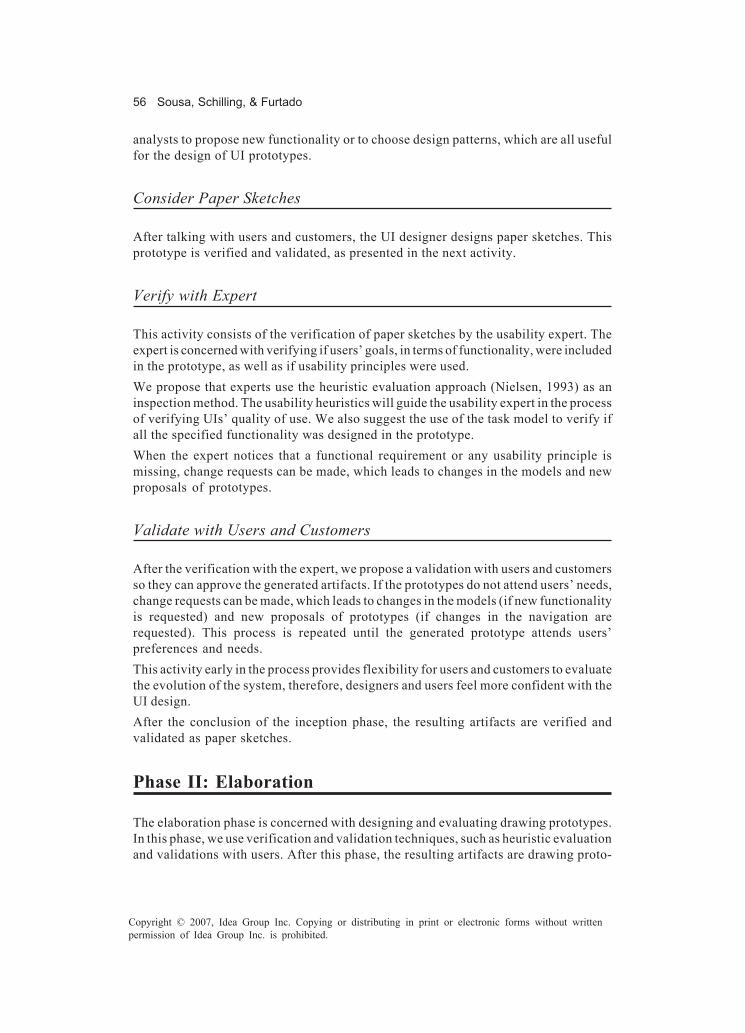
56 Sousa, Schilling, & Furtado
Copyright © 2007, Idea Group Inc. Copying or distributing in print or electronic forms without writtenpermission of Idea Group Inc. is prohibited.
analysts to propose new functionality or to choose design patterns, which are all usefulfor the design of UI prototypes.
Consider Paper Sketches
After talking with users and customers, the UI designer designs paper sketches. Thisprototype is verified and validated, as presented in the next activity.
Verify with Expert
This activity consists of the verification of paper sketches by the usability expert. Theexpert is concerned with verifying if users’ goals, in terms of functionality, were includedin the prototype, as well as if usability principles were used.We propose that experts use the heuristic evaluation approach (Nielsen, 1993) as aninspection method. The usability heuristics will guide the usability expert in the processof verifying UIs’ quality of use. We also suggest the use of the task model to verify ifall the specified functionality was designed in the prototype.When the expert notices that a functional requirement or any usability principle ismissing, change requests can be made, which leads to changes in the models and newproposals of prototypes.
Validate with Users and Customers
After the verification with the expert, we propose a validation with users and customersso they can approve the generated artifacts. If the prototypes do not attend users’ needs,change requests can be made, which leads to changes in the models (if new functionalityis requested) and new proposals of prototypes (if changes in the navigation arerequested). This process is repeated until the generated prototype attends users’preferences and needs.This activity early in the process provides flexibility for users and customers to evaluatethe evolution of the system, therefore, designers and users feel more confident with theUI design.After the conclusion of the inception phase, the resulting artifacts are verified andvalidated as paper sketches.
Phase II: Elaboration
The elaboration phase is concerned with designing and evaluating drawing prototypes.In this phase, we use verification and validation techniques, such as heuristic evaluationand validations with users. After this phase, the resulting artifacts are drawing proto-

Method for Evaluating User Interfaces 57
Copyright © 2007, Idea Group Inc. Copying or distributing in print or electronic forms without writtenpermission of Idea Group Inc. is prohibited.
types validated according to usability requirements and patterns. The description of theactivities and artifacts in this phase is presented as follows.
Use Design Patterns
In order to guarantee the quality of the product and efficiency of the project, we suggestthe use of design patterns for graphical UIs. These patterns will guarantee that weelaborate and develop UIs following already verified and validated parameters, which canbe incremented by the reports generated in the end of the transition phase.
Consider Drawing Prototypes
UI designers are responsible for designing drawing prototypes based on paper sketchespreviously validated, and on usability patterns. These prototypes are verified andvalidated by the following two activities.
Verify with Expert
This activity consists of verifying the usability of drawing prototypes by experts. Wepropose that experts use the heuristic evaluation approach (Nielsen, 1993) as aninspection method to verify whether or not certain usability principles are present in theprototype.When the expert notices that any usability principle is missing, change requests can bemade, which leads to new proposals of prototypes. At this moment, it is not necessaryto make changes in the models because this approach evaluates the quality of use, notfunctionality aspects, which were evaluated in the previous phase.
Validate with Users and Customers
After verification with the expert, a validation is proposed to users and customers so theycan approve the generated prototypes. At this moment, users and customers evaluatethe used usability patterns and the style guide. This process is repeated until thegenerated prototype attends users’ preferences and constraints. If the prototypes do notattend users’ needs, change requests can be made, which leads to new proposals ofprototypes.After the conclusion of the elaboration phase, the resulting artifacts are verified andvalidated drawing prototypes, which support development, tests, and deploymentactivities.

58 Sousa, Schilling, & Furtado
Copyright © 2007, Idea Group Inc. Copying or distributing in print or electronic forms without writtenpermission of Idea Group Inc. is prohibited.
Phase III: Construction
In this phase, the UI is developed and the application is integrated with it. Consideringsoftware engineering, we propose functionality tests of an executable prototype (i.e., aproduct with some functionality) or the final product (i.e., a product with all thefunctionality), using functional test cases.The activities and artifacts in this phase are presented as follows.
Implement and Integrate
These activities consist of developing the UI and integrating it with the application. Theintegrated product, either a prototype or the final system, can be useful for evaluatingthe navigation, interactivity, and functionality aspects.
Elaborate Test Cases
Test cases can be elaborated starting in the inception phase, using paper sketches, theycan then be updated in the elaboration phase, using drawing prototypes, and finishedin this activity. This artifact focuses on the system functionality, not on nonfunctionalaspects.The technique used to define test cases includes the following topics: association to ause case, specification of the item to be tested, preconditions to execute before testing,identification of valid and invalid inputs, and the expected outputs. The actual outputsare compared with the expected outputs described in the test cases and this comparisonis used as validation of the use case.
Verify with Expert
This activity consists of the verification of the functionality of the product by usabilityexperts and developers. Examples of aspects that are verified are: consistency of theoutputs, navigation, existence of error messages, results after clicking on objects, as wellas other aspects identified in the test cases.After this verification, developers and experts can generate change requests to correctthe errors; which leads to the repetition of the implementation and integration activities.After the conclusion of the construction phase, the resulting artifact is the integratedproduct, which is tested with consideration to usability aspects in the transition phase.

Method for Evaluating User Interfaces 59
Copyright © 2007, Idea Group Inc. Copying or distributing in print or electronic forms without writtenpermission of Idea Group Inc. is prohibited.
Phase IV: Transition
This phase comprehends, in general terms, the preparation of the test environment, whichcan be a test laboratory or the environment where the system is used. With considerationto semiotic engineering, we use some validation techniques and artifacts. The descrip-tion of the activities and artifacts in this phase is presented as follows.
Prepare the Environment
To prepare the environment, we suggest the installation of the system, software forcapturing the system’s use, and equipment, such as video cameras and necessaryhardware devices. We also suggest the creation of questionnaires and checklists.The test laboratory must be similar to the real user environment — with considerationto physical structure, climate, sound aspects, and equipment — in order to allow usersto live the same conditions of the real environment. There should be a room where thetest takes place and another one for observation.
Install the Product
In this activity, the product is installed, either a partial version or the final version of thesystem, in order to allow users to use the system in their real environment. Thisinstallation allows the tests to be performed.
Usability Tests “with Users”
This evaluation is performed with users. In it, evaluation techniques, proposed bysemiotic engineering, are used, such as: recording, observation, questionnaires, and soon.Before starting the tests, the usability expert talks with the user in order to: clarify thatthe system is under evaluation, not him/her; present the scenario used for the test; andmake the user feel comfortable; which are aspects that influence the final results.Observers that are in the observation room should fill out the questionnaires andchecklists.This activity can be divided in two moments, the first one, when the user interacts withthe system to perform a task of his/her own interest; the second one, when the expertrequires the user to perform a specific task.In this activity, navigability, interactivity, and acceptability will be evaluated.

60 Sousa, Schilling, & Furtado
Copyright © 2007, Idea Group Inc. Copying or distributing in print or electronic forms without writtenpermission of Idea Group Inc. is prohibited.
Use Observations/Checklist/Questionnaires
Observations, questionnaires, and checklists are artifacts and techniques proposed bythe semiotic engineering in order to verify the user-system interactivity and communi-cability. Experts and observers will use these artifacts during the tests, which result inthe definition of the quality of the interactive system. These results can lead to changerequests for developers to correct the detected mistakes.Users’ comments and the actual execution of the tests will be recorded to help in theanalysis of the results of the questionnaires and of users’ observations.
Make Corrections
In this activity, developers make corrections proposed by experts after the tests. Afterthe changes are made, users validate the product.
Deliver the Evaluated Product
As a result of the process, we have the results of evaluations, which are useful for futureversions; and we also have a verified and evaluated product according to a set oftechniques proposed by usability, software, and semiotic engineering.If the product is a final version of the system, it is ready to be delivered for use. If it isa partial version (e.g., executable prototype), the professionals need to perform theactivities in the construction phase, then in the transition phase, until the productreaches its final version.
Elaborate Reports
The results obtained will be used as a basis for the elaboration of evaluation reports,which propose adaptations in the used patterns and in the creation of new patterns thatcan be used in future iterations.
Case Study
In this chapter, we describe the case study of this research work, which is concerned withthe evaluation of UIs for the SBTVD project, focusing on the applications: electronicportal, insertion of texts, and help.

Method for Evaluating User Interfaces 61
Copyright © 2007, Idea Group Inc. Copying or distributing in print or electronic forms without writtenpermission of Idea Group Inc. is prohibited.
Introduction
The digital TV represents digital and social inclusion for a great part of the Brazilianpopulation, especially for people less privileged, who do not have access to computers,and therefore, cannot access the Internet.The SBTVD must be adapted to the socioeconomic conditions of the country, as well asallow the use of conventional TV sets already in large use in the country in order todecrease risks and costs for the society.The digital TV creates various possibilities of interaction between the TV and the user,such as: exchange of text or voice messages, virtual chats, searches for a favorite show,access to information about the government, and so on. These possibilities are differentfrom the characteristics of the conventional TV, in which the user plays a passive role.In the following section, we describe the performance of the activities proposed by UPiand UPi-Test. It is important to point out that the SBTVD is still under development. Thatis the reason why we cannot demonstrate all the activities of the process.
Phase I: Inception
Talk with Users and/or Customers
This activity was difficult to perform in this project because there is an almost unlimitednumber of users and/or customers. Fortunately, there were specific and clear specifica-tions, established by the Brazilian government. Such specifications were used asrequests from users and customers.To define the scope of the application under our responsibility (access portal), we hadmeetings with representatives of the government and with other institutions that areparticipating in the project. These meetings were supported with brainstorming and theresulting decisions were analyzed and were shared with all the institutions through e-mailsand discussion lists.After these meetings, we decided that the portal will consist of a main application that allowsthe access to all other applications in the SBTVD, which can be: electronic mail, electroniccommerce, EPG, help, electronic government, and so on.
Obtain Users’ and Customers’ Preferences and Constraints
The SBTVD project is concerned with various users’ profiles, including the ones whoare and those who are not used to technology, but not including the ones with any kindof disabilities.In order to identify their possible preferences and constraints, we studied existingsystems; we had many meetings and workshops. The opinions of all the participants inthe project were taken into consideration because we can also be considered to bepotential users.
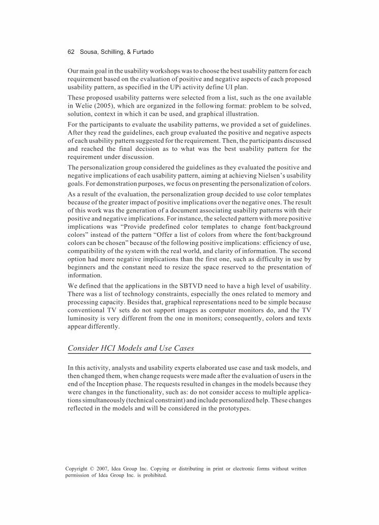
62 Sousa, Schilling, & Furtado
Copyright © 2007, Idea Group Inc. Copying or distributing in print or electronic forms without writtenpermission of Idea Group Inc. is prohibited.
Our main goal in the usability workshops was to choose the best usability pattern for eachrequirement based on the evaluation of positive and negative aspects of each proposedusability pattern, as specified in the UPi activity define UI plan.These proposed usability patterns were selected from a list, such as the one availablein Welie (2005), which are organized in the following format: problem to be solved,solution, context in which it can be used, and graphical illustration.For the participants to evaluate the usability patterns, we provided a set of guidelines.After they read the guidelines, each group evaluated the positive and negative aspectsof each usability pattern suggested for the requirement. Then, the participants discussedand reached the final decision as to what was the best usability pattern for therequirement under discussion.The personalization group considered the guidelines as they evaluated the positive andnegative implications of each usability pattern, aiming at achieving Nielsen’s usabilitygoals. For demonstration purposes, we focus on presenting the personalization of colors.As a result of the evaluation, the personalization group decided to use color templatesbecause of the greater impact of positive implications over the negative ones. The resultof this work was the generation of a document associating usability patterns with theirpositive and negative implications. For instance, the selected pattern with more positiveimplications was “Provide predefined color templates to change font/backgroundcolors” instead of the pattern “Offer a list of colors from where the font/backgroundcolors can be chosen” because of the following positive implications: efficiency of use,compatibility of the system with the real world, and clarity of information. The secondoption had more negative implications than the first one, such as difficulty in use bybeginners and the constant need to resize the space reserved to the presentation ofinformation.We defined that the applications in the SBTVD need to have a high level of usability.There was a list of technology constraints, especially the ones related to memory andprocessing capacity. Besides that, graphical representations need to be simple becauseconventional TV sets do not support images as computer monitors do, and the TVluminosity is very different from the one in monitors; consequently, colors and textsappear differently.
Consider HCI Models and Use Cases
In this activity, analysts and usability experts elaborated use case and task models, andthen changed them, when change requests were made after the evaluation of users in theend of the Inception phase. The requests resulted in changes in the models because theywere changes in the functionality, such as: do not consider access to multiple applica-tions simultaneously (technical constraint) and include personalized help. These changesreflected in the models and will be considered in the prototypes.

Method for Evaluating User Interfaces 63
Copyright © 2007, Idea Group Inc. Copying or distributing in print or electronic forms without writtenpermission of Idea Group Inc. is prohibited.
Analyze Existing Systems
In this activity, we researched on the Internet in order to find digital TV systems alreadyin use. It was very difficult to find them because there are few systems available for accessin the Internet.This analysis was used to identify some UI design patterns for the digital TV, such as:upper and bottom options bar, menu on the left, navigation icons, interaction buttons,and so on.
Consider Paper Sketches
After the analysis of existing systems, UI designers elaborated paper sketches (Figure2). However, they needed to be redesigned after the evaluation of users in the end of theinception phase, which resulted in change requests.Some change requests resulted in the following changes in the prototypes: transfer thebar from the top to the bottom of the screen, include the “TV” button in the bar whenaccessing an application or in the portal; include the “Portal” button in the bar whenaccessing an application, take off activated icons (because of technical restrictions), andgive a preview of the requested options of personalization. However, other requestsresulted in changes in the models as well as in the prototypes, such as the ones mentionedin the activity “Consider HCI models and use cases.”
Figure 2. Paper sketch: Personalization
Portal Watch TV Color Font Help
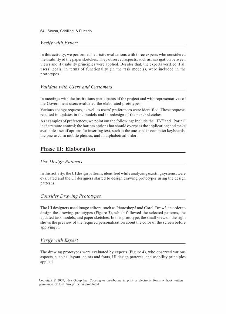
64 Sousa, Schilling, & Furtado
Copyright © 2007, Idea Group Inc. Copying or distributing in print or electronic forms without writtenpermission of Idea Group Inc. is prohibited.
Verify with Expert
In this activity, we performed heuristic evaluations with three experts who consideredthe usability of the paper sketches. They observed aspects, such as: navigation betweenviews and if usability principles were applied. Besides that, the experts verified if allusers’ goals, in terms of functionality (in the task models), were included in theprototypes.
Validate with Users and Customers
In meetings with the institutions participants of the project and with representatives ofthe Government users evaluated the elaborated prototypes.Various change requests, as well as users’ preferences were identified. These requestsresulted in updates in the models and in redesign of the paper sketches.As examples of preferences, we point out the following: Include the “TV” and “Portal”in the remote control; the bottom options bar should overpass the application; and makeavailable a set of options for inserting text, such as the one used in computer keyboards,the one used in mobile phones, and in alphabetical order.
Phase II: Elaboration
Use Design Patterns
In this activity, the UI design patterns, identified while analyzing existing systems, wereevaluated and the UI designers started to design drawing prototypes using the designpatterns.
Consider Drawing Prototypes
The UI designers used image editors, such as Photoshopâ and Corel Drawâ, in order todesign the drawing prototypes (Figure 3), which followed the selected patterns, theupdated task models, and paper sketches. In this prototype, the small view on the rightshows the preview of the required personalization about the color of the screen beforeapplying it.
Verify with Expert
The drawing prototypes were evaluated by experts (Figure 4), who observed variousaspects, such as: layout, colors and fonts, UI design patterns, and usability principlesapplied.
Method for Evaluating User Interfaces 65
Copyright © 2007, Idea Group Inc. Copying or distributing in print or electronic forms without writtenpermission of Idea Group Inc. is prohibited.
Validate with Users and Customers
This activity is yet to be fully performed in this project, currently; we have finished thedocument that specifies the SBTVD graphical UI, which is going to be evaluated byrepresentatives of the Brazilian Government.We scheduled a workshop with the other institutions participants of the project toevaluate the drawing prototypes (Figure 5). They requested us to elaborate otheralternatives of UIs (including association of options in the UI with options on the remotecontrol), increase the size of the options and fonts in the upper bar, and change the wayto differentiate the selected option.
Figure 3. Drawing prototype: Personalization
Figure 4. Verification with expert

66 Sousa, Schilling, & Furtado
Copyright © 2007, Idea Group Inc. Copying or distributing in print or electronic forms without writtenpermission of Idea Group Inc. is prohibited.
Phase III: Construction
Implement and Integrate
The implementation of the portal has not started yet. However, the developers have beenstudying and implementing simple applications for the digital TV, such as three possi-bilities of insertion of text (the one used in computer keyboards (‘qwert’), the one usedin mobile phones, and in alphabetical order).
Figure 5. Validation with users
Test case Personalization
Test items Changes in font and background color Changes in font size
Pre-conditions The user must be accessing the portal
Inputs The user must select a type of personalization: Font color The user selects green
Expected results The portal must present the personalized content with a green background color
Table 1. Test case: Personalization
Method for Evaluating User Interfaces 67
Copyright © 2007, Idea Group Inc. Copying or distributing in print or electronic forms without writtenpermission of Idea Group Inc. is prohibited.
Elaborate Test Cases
The elaboration of functional test cases has started since the inception phase, when usecases and paper sketches were elaborated. Functional requirements were selected andthe associated test cases were elaborated: structure applications, access applications,access help and personalization (Table 1).
Verify with Expert
In this activity, the programmers and the experts verify the applications using the testcases for guidance. Some of these evaluations were done in the small applicationsdeveloped for insertion of text.
Phase IV: Transition
The usability experts and the developers have prepared the test environment. For that,they have: prepared the physical structure (e.g., TV, video camera, couch, computer tosimulate the set-top box, etc.) and installed the necessary software (i.e., software tocapture the user interaction with the TV, Linux Operating System, Java Virtual Machine,and applications to be tested).A group of three usability experts were responsible for performing the following activitiesbefore the tests started: First, they defined a questionnaire to apply with users in orderto understand their characteristics and familiarity to the DTV technology. Second, theyselected appropriate metrics (e.g., number of errors, number of access to the help, etc).Third, they created a checklist based on Nielsen’s usability goals and on the metrics fromthe previous step. Fourth, they prepared the environment with a DTV, a couch, and acenter table in order to make users feel at home. Fifth, they selected ten users withdifferent profiles between the ages of 18 and 26.When the users arrived, each one at a time was taken to the DTV room, where a usabilityexpert explained the goals of the test; applied the questionnaire; and defined a specificgoal to be achieved while interacting with the DTV. While the user interacted with theapplication, usability experts filled out the checklist in the visualization room, where wemonitored the environment and the user with a camera and captured the interaction withthe DTV using specific software.
Findings and Future Works
After the tests, we evaluated the checklists and generated reports with solutions to theproblems encountered during the tests. These reports contain comments about theicons, the navigation, and the help module of the portal application.

68 Sousa, Schilling, & Furtado
Copyright © 2007, Idea Group Inc. Copying or distributing in print or electronic forms without writtenpermission of Idea Group Inc. is prohibited.
• No user realized the possibility of navigation through the numbers associated toeach icon, which represents an interactive application (see Figure 6).
• When they were told about this, they used it and said it was very practical.• For them, the icons were not a natural representation, but they did not want to give
any opinion about possible solutions.• Some users did not notice the application that was selected. They said it was better
to have a big square around the icon instead of the current selection.• When the users were confused and wanted some help, they did not look for it in
the portal (the blue option in the bottom bar that activates the help module). Someusers activated the menu button of the remote control and others waited for theevaluator to tell them what was necessary to do to obtain the help.
• As the bottom bar is used as a design pattern to put the navigation options, andas each option is different depending on the situation (the application beingexecuted), the users got very confused. We realized they looked at this bar onlyonce, and then they did not look at it any more. After memorizing the options, theywanted to use them all the time, but the color was different, so they made manynavigation errors.
From the execution of these tests, we were able to quantify the results: 85% of the usersfound the system easy to use, easy to read, and easy to navigate, but on the other hand,50% had difficulties in identifying that an option was selected and in getting out of anunexpected situation.Our next step is to make the necessary changes that are related to improving the layout,color contrast, and icon selection. In addition, the next tests will be done with the elderlyin order to investigate people who are not used to interaction devices.
Figure 6. The portal application

Method for Evaluating User Interfaces 69
Copyright © 2007, Idea Group Inc. Copying or distributing in print or electronic forms without writtenpermission of Idea Group Inc. is prohibited.
Conclusion
In this chapter, we present a new method, which focuses on integrating differenttechniques of usability, semiotic and software engineering. The aims are to design usableUIs following a model-based UI design process and to facilitate the test process by usingthe evaluated HCI models. In this manner, we hope to contribute to the development ofinteractive systems that are easy for users to learn and use, and to help testers inperforming their usability tests in an efficient manner.As main contributions, we focus on evaluating the usability of UIs with the constantparticipation of users and customers. Besides that, the integration of various approachesresults in positive outcomes for the prototypes, as well as for multidisciplinary teammembers, who are better integrated and can have their knowledge enhanced, since theyare continuously exchanging information and experiences.
References
Baranauskas, M. C. C., & Rocha, H. V. da. (2003). Design e Avaliação de InterfacesHumano-Computador, NIED–Núcleo de Informática Aplicada à Educação,UNICAMP–Universidade Estadual de Campinas.
Coyette, A., Faulkner, S., Kolp, M., Limbourg, Q., & Vanderdonckt, J. (2004). SketchiXML:Towards a multi-agent design tool for sketching user interfaces based on UsiXML.In P. Palanque, P. Slavik, & M. Winckler (Eds.), 3rd Int. Workshop on Task Modelsand Diagrams for User Interface Design (pp. 75-82). New York: ACM Press.
Gould, J. D., & Lewis, C. (1985). Designing for usability: Key principles and whatdesigners think. Communications of the ACM, 28(3), 300-311.
ISO 13407. (1999). Human-centred design processes for interactive system teams.Kruchten, P., Ahlqvist, S., & Bylund, S. (2001). User interface design in the rational
unified process. In M. Van Harmelen (Ed.), Object modeling and user interfacedesign (pp. 45-56). New York: Addison-Wesley.
Lewis, C. (1982). Using the “thinking-aloud” method in cognitive interface design (IBMResearch Rep. No. RC9265, #40713). Yorktown Heights, NY: IBM Thomas J.Watson Research Center.
Myers, G. J. (2004). The art of software testing. New York: John Wiley & Sons.Nielsen, J. (1993). Usability engineering. Boston: Academic Press.Pressman, R. S. (1995). Engenharia de Software. São Paulo: Makron Books.Schilling, A., Madeira, K., Donegan, P., Sousa, K., Furtado, E., & Furtado, V. (2005). An
integrated method for designing user interfaces based on tests. In Proceedings ofthe ICSE 2005 Workshop on Advances in Model-Based Software Testing, (pp. 27-31). St. Louis, MO: ACM.

70 Sousa, Schilling, & Furtado
Copyright © 2007, Idea Group Inc. Copying or distributing in print or electronic forms without writtenpermission of Idea Group Inc. is prohibited.
Sommerville, I. (2001). Software engineering. New York: Addison-Wesley.Souza, C. S. de, Barbosa, S. D. J., & Silva, S. R. P da. (2001). Semiotic engineering principles
for evaluating end-users programming environments. Interacting with Comput-ers, 13(4), 467-495.
Sousa, K. S., & Furtado, E. (2004). UPi — A unified process for designing multiple UIs.In IEEE Computer Society, Proceedings of the International Conference onSoftware Engineering, Edinburgh, Scotland (pp. 46-53). Edinburgh, Scotland:ACM.
Welie, M. van (2005). Retrieved September, 15, 2005, from http://www.welie.com

Automated Software Testing 71
Copyright © 2007, Idea Group Inc. Copying or distributing in print or electronic forms without writtenpermission of Idea Group Inc. is prohibited.
Chapter IV
AutomatedSoftware Testing
Paula Donegan, Instituto Atlântico, Brazil
Liane Bandeira, Instituto Atlântico, Brazil
Cristina Matos, Instituto Atlântico, Brazil
Paula Luciana da Cunha, Instituto Atlântico, Brazil
Camila Maia, Instituto Atlântico, Brazil
Abstract
This chapter approaches paramount aspects related to test automation, introducingthe importance of implementation in the software market and essential bases, such asadjustment to the organizational reality and establishment of an efficient strategy.Types of tools and directives for a successful implantation are presented. Test automationhas been considered the main measure taken to enhance test efficiency — fundamentalin the software-development process. Responsible for verifying and/or validating thequality of the executable product compared to performed documentation and clientrequirements. Therefore, with the chapter content here provided, we aim to provide thereader with an understanding of test automation and grant relevant orientations toassist implementing it.

72 Donegan, Bandeira, Matos, da Cunha, & Maia
Copyright © 2007, Idea Group Inc. Copying or distributing in print or electronic forms without writtenpermission of Idea Group Inc. is prohibited.
Introduction
Given the growing complexity of applications and new technologies, such as the adventof the client/server environment (in particular Web applications), the effort necessaryfor application testing has increased.To assure that software conforms to requirements, various test stages may be identified:unit, integration, system, and acceptance. Bugs’ impact increases with the evolution ofthe test stage in which they are found, in other words, the cost of detecting errors duringunit test is less than integration and system tests.Each use case has test objects that may need to be retested several times during theproject, demanding resources. These retests normally are required when a new function-ality is added or when a bug is corrected, because there is no guarantee that the changesmade will impact negatively on other parts already constructed. Therefore, the assistanceof a tool capable of repeating a test already executed in the past is quite interesting.Besides, multiple execution paths and diversity of possible inputs and outputs of anapplication complicate the execution of manual tests, which may be simplified byautomation. In addition, performance, load and volume tests are examples of tests thatare difficult to be accomplished without the help of automated testing tools. There arealso some types of tests that are almost impossible to be executed manually, for example,a test to verify a system’s performance with thousands or millions of simultaneousaccesses or having to use an enormous amount of data.Automating software tests speeds development and reduces retesting effort spent ineach stage, thus reducing time and cost. However, this reduction is normally noticed onlyafter a while, because there are high investments in the implantation stage, such asorganizational needs, training, and tools acquisition. Automation allows increase ofamplitude and depth of developed tests.Testing automation might or might not be helpful. It allows one to take advantage of idlemachine time (i.e., the period in which the developer is not working) to execute tests.Therefore, test execution can be more effective and waste less resources.
Background
Automated software testing is an activity that seems to have obvious benefits: tests maybe executed swiftly, are more consistent, and may be repeated various times withoutincreasing cost. However, it is not a trivial activity and requires effective planning andelaborate test-case definition, as well as other characteristics, which will be explained inmore detail later in this chapter. Benefits and risks, possible tools, an implantationmethodology and directives for script generation are also described.An automated test between different phases of the development process has the purposeof verifying if what was constructed from that stage backwards is correct and is adequateas an input for the next stage. An example would be a programmer testing a softwarecomponent before doing the integration of components.
Automated Software Testing 73
Copyright © 2007, Idea Group Inc. Copying or distributing in print or electronic forms without writtenpermission of Idea Group Inc. is prohibited.
The generated test process is automated and capable of ensuring that the systemlogically operates according to the code by executing the functions through a series oftest cases.With a tool, you can expect the test script to conduct the verification processes andreturn results that verify whether the product under test meets code logic.A test engineer usually follows a procedure to decide whether a problem found is a defect.However, an automated test tool makes decisions based on methods invocation, duringwhich it detects errors and defects. Thus, the tool makes an effort to remind thedevelopers of the importance of adopting a good error-handling technique.But, can a tool verify that all test tasks have been performed? The answer is based onthe requirements of your organization and on the architecture of the software project (Li& Wu, 2004).Tests to validate a product against specified client requirements are more subjective andcannot always be automated. An example is a test executed by a user in a beta-program.
Manual Testing vs. Automated Testing
Software testing is necessary to guarantee the quality of a software product, may beperformed during the whole software development process, in a manual, automated orhybrid manner, using different types of tests and tools.Automated software testing simulates system behavior using tools. The test actionsperformed on the application are specified in code (scripts and test classes). In a contextwhere required tests are not possible or viable to be executed manually, automatedsoftware testing is very important. As examples in which automated tests are indicated,one has Automated tests are used in regression, load, performance, and endurance testsand tests involving a vast amount of data.Regression tests require testing all constructed functionalities after one of them ischanged or a new one is inserted. Automation helps in this process, providing repetitionof tasks already executed. Thus, functionality tests already recorded may be executedagain, decreasing retest efforts.For load tests, a high amount of users simultaneously accessing the application isnecessary (e.g., in the order of 100; 1,000; and 10,000). How can such a test be performed?Automation is a resource that can easily simulate this scenario.When using test performance, an automation test tool is used to capture time measure-ments each time they are executed. Performance degradations can be detected bycollecting these measurements and reviewing them as time series (Karner, 1993).Endurance testing requires automation. In this type of test, a specific applicationbehavior is observed with the execution of its functionalities for a certain amount of time— weeks or months. This way, it is possible to detect problems like memory leaks, stackcorruption and wild pointers.

74 Donegan, Bandeira, Matos, da Cunha, & Maia
Copyright © 2007, Idea Group Inc. Copying or distributing in print or electronic forms without writtenpermission of Idea Group Inc. is prohibited.
Some specific tests — such as installation, configuration, and usability tests and specifichardware operations tests — require a strong human intervention, as well as a specifichuman evaluation and validation. Manual tests are recommended for these kinds of tests,being executed by at least one person, following a test procedure with application inputand output data.Test automation has a high cost. Training and scripts maintenance are necessary and,in case the tools used are not free, licenses are needed according to the number of users.However, automation has become essential given to systems’ high complexity, need ofperformance and stress testing, resulting in increase of testing time and cost, reductionof software quality and, after the recognition of importance of software tests, pressureover project development teams has increased.Test execution may also be performed with hybrid methods, characterized by applyingjointly manual and automated techniques in the same project. The choice will depend ona thorough analysis of time and resources available and test complexity. The degree ofmaintenance and human intervention must be taken into consideration given to appli-cation modifications.Many tests are not executed many times during a project life cycle. In these cases it ismore advantageous to execute the tests manually, because efforts employed in theirautomation do not provide large returns. Therefore, it is not recommended to automate100% of the tests.Manual and automated tests should not be compared only in terms of time, effort, andcost, because the value of a test is especially in the information it provides. In the sameway, manual and automated tests are not allowed to be compared in many cases, becausethey provide distinctive information, as seen before, for every type of test, one of themis normally indicated.However, in certain situations it might be a reasonable goal to create the most extensiveautomated test suite, such as contractual or regulatory reasons, when it is necessary toprove that the final version passed a strong battery of tests; when tests will be deliveredwith the product so that customers can also run the tests themselves; when the producthas stringent requirements for backwards compatibility, remaining for many versions, orwhen the only way to test some products is by writing programs to exercise them (Kaner,Bach, & Pettichord, 2002).
Overview of Automated Testing
Nowadays automated testing is considered the main resource to improve the efficiencyof a test process (Rios & Moreira, 2003), using tools so that the computer is responsiblefor assistance, design achievement, execution or tests control. Information collectionand their quick dissemination are assisted by automated tests to provide a fasterfeedback to the development team (Kaner, 2002).Tools to execute automated tests normally simulate the use of an application by severalusers simultaneously, a high load of data processing, as well as repetition of taskspreviously executed. Besides, automating regression tests is of great relevance for the

Automated Software Testing 75
Copyright © 2007, Idea Group Inc. Copying or distributing in print or electronic forms without writtenpermission of Idea Group Inc. is prohibited.
maintenance phase, since tests executed during development may be repeated in newtests, when the system is already in production.When the automation does not apply to the entire test process, it can be used to executepunctual tests. This occurs normally with some types of tests — such as load andperformance tests — because they are truly difficult to be performed without the help ofa tool, requiring big effort and many computational resources.The preparation of automated tests takes more time than manual tests. This is mainly aconsequence of high effort and cost necessary to generate and maintain automationcode. Therefore, so that the investment may bring satisfactory return on investment,automation must help to achieve the specific tests mission (Kaner, 2002), providing asupply of functional and nonfunctional tests.Automation must be introduced in a context where the test process is well performed, withwell-defined activities and with a mature and experienced test team. Otherwise, automa-tion will not assist the achievement of test objectives. For this reason, test processesmust be fixed before automating them.Specific management treatment is required, in other words, planning, execution, andcontrol, because normally automation is characterized by its innovation and highinvestments, complexity, and risks. Without this management, the expected benefits maynot be achieved, besides consuming resources and dispersing the team from their testobjectives, consequently interfering on the quality of tested products. Moreover,previous strategies and planning definitions are necessary, so that risks are controlled,possibility of scripts reuse is increased and automation optimized.Automated testing tools do not replace testers, nor will their work be simpler. Actuallytheir effort will be redirected to essential activities of the test automation process. Forthis reason, it is of great relevance to prepare the group, because the success ofautomated testing depends predominantly on their skills.
Test-Stages Automation
Test automation may be applied to diverse stages: unit, integration, and systemic. Eachone has peculiar characteristics and is implemented in a different way. Next, these aspectswill be shown for each test stage.
Automated Unit Testing
Unit tests consist of testing components individually. The tester verifies the inputdomain only for the unit in question, ignoring the rest of the system. These tests requirecode construction executed during depuration mode.The developer has the responsibility to ascertain that units are correctly constructed,analyzing code, comparing it with the system’s specification and checking if anyfunctionality is missing or was not completely developed.

76 Donegan, Bandeira, Matos, da Cunha, & Maia
Copyright © 2007, Idea Group Inc. Copying or distributing in print or electronic forms without writtenpermission of Idea Group Inc. is prohibited.
Tests and error corrections may be made at any stage of the development cycle.Nevertheless, some authors like Boehm (1981), have shown that the cost of searchingand finding errors increases while the development advances. It is cheaper to fix defectsduring the codification stage.Procedure to implement unit testing:
1. Prepare test environment.2. Define input domain based on requirements and use cases.3. Define, for every input, expected output based on requirements and use cases.4. Implement components to be tested.5. Group unit tests in collections of components.6. Implement unit tests.7. Execute unit testing.8. Fix component tested, if there is an error.9. Execute step 8 while any error remains.
Unit testing consists basically of:
1. Variables initiation, including database population.2. Business rules or input functions are applied.3. Destruction of variables, including the cleaning up of data input to data base.4. Comparison between results of applied function with expected results, failing in
case they differ.
Grouping unit tests forms a tree, where the leaves consist of the unit tests and in the othernodes are the groupings of unit tests. This technique allows automating and executingall tests, a subset of them, or each one individually.Unit test automation enables dynamic problem detection, generating automated reports,and facilitates execution of regression tests, which are necessary for every meaningfulcode update.
Automated Integrated Testing
Integrated tests are performed to test various parts of the system (components, modules,applications, etc.) that were separately developed in a set. Integration tests are executedafter each of the system’s parts has been tested individually, using unit tests or systemictests, in case of applications that communicate (with each other).

Automated Software Testing 77
Copyright © 2007, Idea Group Inc. Copying or distributing in print or electronic forms without writtenpermission of Idea Group Inc. is prohibited.
Analyzing the time line, you can notice that integrated tests are mainly performed aftera unit test and before systemic tests, normally are executed by developers that create theirown builds and test integrates units or by a specialized testing team.Procedure to implement integrated tests:
1. Prepare test environment, using test data and test server, which are configured tosimulate the production environment.
2. Identify test cases based on requirements and architecture.3. Detail procedures for each test case.4. Implement integrated tests.5. Execute integrated tests.6. Analyze results. If errors are found, they must be registered in the problem reports
tool and associated to responsibles for the corresponding corrections. If none arefound codification may stop.
7. Fix problems encountered.8. Execute tests again. After ending it, return to step 6.
Automated System Testing
System testing is the most misunderstood and most difficult testing process. Systemtesting is not a process of testing the functions of the complete system or program,because this would be redundant with the process of function testing (Myers, 2004).System testing compares the system or program with its original objectives (require-ments).In this stage a test environment, compatible with the one in which the system or programwill be used, is necessary.Various test types are performed during this stage: usability, functionality, performance,stress, and so on. Some of these may be automated to make execution more agile,especially in case of regression tests.Systemic tests may be automated in several ways, but a list follows with their basicactivities:
1. Prepare test environment, installing and configuring necessary hardware andsoftware.
2. Design test cases.3. Define automation strategy.4. Select project scope for automation.5. Implement systemic test scripts for each test case.

78 Donegan, Bandeira, Matos, da Cunha, & Maia
Copyright © 2007, Idea Group Inc. Copying or distributing in print or electronic forms without writtenpermission of Idea Group Inc. is prohibited.
6. Execute systemic test.7. Analyze results. If errors are found, they must be registered in the problems report
tool and associated to responsibles for the corresponding corrections.8. Fix problems found.9. Generate reports with tests status.10. Execute tests again, returning to step 6 after finishing them.
Automation Techniques
Automated functional test tools make use of some techniques that differentiate them-selves basically because of the contents of the generated scripts: record & playback,scripts programming, data-driven and keyword-driven. These techniques will be ex-plained as follows:
• Record and playback: Technique that consists of recording a test execution madeon the application’s interface and playing back this execution later. The generatedscripts contain unalterable data, test procedures, and expected results. Theadvantage of this technique is the simplicity of generating scripts. However, thereis a high sensibility to changes, which restricts a script’s lifetime. For example, asimple change of an interface may lead to the necessity of recording again all thescripts, implying a high script maintenance cost.
• Scripts programming: Considering the components of the generated scripts, thistechnique is similar to the one above. However, this one allows updating generatedscripts. With this resource, script programming has a higher rate of reuse, longerlifetime, and less difficulties to be maintained, compared to the technique of Record& Playback. Nevertheless, there is still a big volume of scripts and high-mainte-nance cost (Fantinato, Cunha, Dias, Mizuno, & Cunha, 2004).
• Data-driven: This is a technique that approaches test-data extraction throughscripts, storing them in separate files. Therefore, scripts will only contain testprocedures and actions for the application. This technique is useful for tests usingdifferent inputs and combinations of scripts with common test procedures (Kaner,2002). This way, maintenance requires a reduced effort when it is necessary toinclude, update, or delete any test data. However, this technique depends on thetest-execution logic, in other words, if any step is added to the procedure (orremoved) the script needs to be generated again.Nevertheless, it allows automating in parallel: test data can be created while testprocedures are being generated. The extraction of test data from scripts providestests that are easy to understand and revise. Many test tools include direct supportfor the technique data-driven (Kaner, 2002).
• Keyword-driven: Based on retrieving test procedures from scripts, remaining onlytest data and specific test actions, which are identified by keywords. This resource’soperation, being invoked by keywords and even receiving parameters, is similar to

Automated Software Testing 79
Copyright © 2007, Idea Group Inc. Copying or distributing in print or electronic forms without writtenpermission of Idea Group Inc. is prohibited.
that of structured-program functions. An important enhancement of this techniqueis the reduction of script-maintenance effort if there is incorporation, removal, ormodification of any step of a test-procedure execution (Fantinato et al., 2004).In spite of tools existent in the market recommending a specific testing technique,the organization needs to establish the most adequate technique according to theirown test context after analyzing all possibilities.
Good Practices for Automation
A list of relevant practices to improve systemic test-script implementation and reusefollows, which may be used according to the adopted technique:
• When recording a script for a test case, some necessary initialization may benecessary — such as database connection, variables, and functions — which canbe shared between test cases of the same use case or even between many use cases.
• Each script may be recorded independently from the others, having its ownvariables, initialization, and so on, although it would be better to share commonobjects for test scripts, in other words, use the concept of modularity. For example,if it is necessary to clean up a database for a specific use case before executing anytest script, or if there are common script steps, a text file to store these steps maybe used and later on can be included at scripts execution time. If these steps change,only one place will have to be modified.
• Another practice is to define functions executing a common activity for manyscripts, and only call it from those scripts.
• A clean and robust code must be implemented. Comments should be made forimportant lines or code blocks. While implementing, possible maintenance may notbe discarded.
• When a flow alteration or verification point in a script is recorded again, there mustbe some care to update only script sections where there really must be a change.
• To delete any garbage shown in a form, before inserting any data, a combinationof keys should be used (“HOME”, “SHIFT+END” and “DELETE”) when recordingan action of data input.
• If test scripts are recorded initially from a prototype (in case the application is stillnot available), it is necessary to certify that names of fields and IDs of clickableicons on screen will not be altered. If they are changed, the script will need an updatelater.
• Dynamic data for test scripts should be used (test data separate of scripts). Theimmediate benefit is that, if additional data is needed, more records can simply beadded; there is no need to modify the test script (Mosley & Posey, 2003).

80 Donegan, Bandeira, Matos, da Cunha, & Maia
Copyright © 2007, Idea Group Inc. Copying or distributing in print or electronic forms without writtenpermission of Idea Group Inc. is prohibited.
Benefits and Risks
The benefits of automated tests are innumerable. Some of them will be described here,as well as risks that were considered most important.A growing number of software versions to be tested exhausts the capacity of manual testsin terms of time, patience, input variation, attributes combination and, as consequence,cost. With advent of increasingly complex, integrated, and critical software, automatedtests have become a necessity.Benefits of test automation may be observed in any test stage, such as unit tests,integrated tests, and systemic tests.Unit testing is a way of efficiently granting an applications quality. In this stage, a bigquantity of errors can be detected and easier corrected. The manual execution of unit testsis a difficult process that consumes time and resources, being practically unviable sincealmost all system units must be tested, depending on the context, such as functions,subroutines, components, or classes.Benefits of automated unit tests are easily noticed. During the project’s life cycle unittests, automation can decrease the costs of rewriting code, because more errors are foundstill in the codification stage. This test stage also grants more security when doingupdates, since the entire set of tests are executed automatically. It is easier for program-mers to write test routines that retain their value in time and assure the correct functioningof units. Besides, automated unit testing provides test results immediately after theirexecution.In integrated tests, where the focus is on systems architecture and integration betweendifferent units developed, it is also indispensable to execute them automatically. Theintegration between system units may occur daily during the development process andit is important to always test the relationships between those components usingautomatic mechanisms, like continuous integration.Automation of systemic tests requires attention and planning, because in this stage thefunctionalities’ behavior is verified according to specified requirements. System testingis conducted at a higher level. During systemic tests, an examination is made ofintegration of parts that make up the entire system (Dustin, Rashka, & Paul, 1999).For each test stage, automation must take into consideration possible software changes.However, systemic test scripts have their execution recorded in an application interface,therefore, there must be a special care avoiding costs of rework. Flexible scripts(dependencies with interface are minimized) can assist scripts maintenance.In general, test automation in any stage allows:
• Test effort reduction: Introduction of automated test tools will not immediatelyreduce the test effort. Experience has shown that a learning curve is associated withattempts to apply automated testing to a new project and to achieve effective useof automated testing.

Automated Software Testing 81
Copyright © 2007, Idea Group Inc. Copying or distributing in print or electronic forms without writtenpermission of Idea Group Inc. is prohibited.
While the testing effort will likely increase at first, a playback on test toolinvestment will appear after the first iteration of the tools’ implementation, due toimproved productivity of the test team.Manual tests must still be performed on the project, while a learning curve may existdue to effort with familiarization and efficiency in the use of the tool (Dustin et al.,1999).
• Schedule reduction: As the testing effort may actually increase, the testingschedule will not experience an initial decrease but may instead become extended.Therefore, permission to increase the schedule is required when initially introduc-ing an automated test tool. Once an automatic testing process is established andeffectively implemented, the project can expect to experience gains in productivityand turnaround time, having a positive effect on schedule and cost (Dustin etal.,1999).
• Improved regression testing: An automated test tool provides simplified regres-sion testing. Automated regression testing can verify in an expedient manner thatno new bugs were introduced into a new build (Dustin et al., 1999).
• Improved focus on advanced test issues: Automated testing allows simple repeat-able tests. A significant amount of tests are conducted on the basic user-interfaceoperations of an application.Besides delaying other tests, the tedium of these tests exacts a very high toll onmanual testers. Manual testing can become stalled due to the repetition of thesetests, at the expense of progress on other required tests. Automated testingpresents the opportunity to move on more quickly and to perform a more compre-hensive test within the schedule allowed. That is, automatic creation of userinterface operability tests gets these tests out of the way rapidly and releases testresources, allowing test teams to turn their creativity and effort to more complicatedproblems and concerns.
• Increased test coverage: Automated testing may increase breadth and depth of testcoverage, yet there will still not be enough time or resources to perform a 100%exhaustive test. Even with automation, testing every combination of a systemexhaustively is impossible. Therefore, there must be strategies (equivalencepartitioning) to select relevant test data.
• Productivity increase: Having increased test coverage, automation also increasesproductivity. Testers may verify more test cases in less time than when usingmanual tests.
• Improved performance testing: Many load-testing tools are available that allowone to automatically test the performance of a system’s functionalities, producingtiming numbers and graphs and thresholds of the system. There is no longer thenecessity to sit with a stopwatch in hand. The objective of performance testing isto demonstrate that a system functions in accordance with its performancerequirement specifications regarding acceptable response time, while processingthe required transaction volumes on a production-size database (Dustin et al.,1999).

82 Donegan, Bandeira, Matos, da Cunha, & Maia
Copyright © 2007, Idea Group Inc. Copying or distributing in print or electronic forms without writtenpermission of Idea Group Inc. is prohibited.
From these benefits, we can observe that automation is essential, because, even with anextremely experienced tester, it is almost impossible to know all the relations andcombinations between attributes of medium- and large-sized applications.Even so, the implementation of a solution for automated tests, even with excellent testtools available, is not trivial and can fail mainly due to:
• Nonqualified test team: An automated tool requires new skills for test analysts,therefore additional training is required. An efficient automation is not that simple.Test scripts automatically generated by the tool during recording must be modifiedmanually, which requires scripting knowledge, so as to make the scripts robust,reusable, and maintainable. To be able to modify the scripts, the test engineer mustbe trained on the tool and the tool’s built-in scripting language (Dustin et al., 1999).
• Inadequate tools: The automation tool must be in accordance to the company’sbusiness needs with the test process introduced. There are many tools thatautomate tests and a correct choice cooperates to fully use features offered. Thereis not a tool clearly superior to other tools for every situation. The choice of themost adequate tool depends on characteristics of applications, test stages to beautomated, as well as the adopted organizational test policy.Simply using tools, by themselves, will not promote a significant quality enhance-ment of developed products, if not accompanied by an adoption of a workmethodology.An incorrect choice may lead to automation failure, once the organizational testingneeds will not be completely suppressed and resources and efforts addressed tomanual tests deviated. Besides, given to the affected credibility, it may be difficultto obtain further investments of higher management to proceed with automationor even to reinforce manual tests.
• Elevated cost with systemic test scripts maintenance: This aspect may notcompensate automation costs. Systemic test scripts have to be flexible enough toeasily support various changes and insertion of new functionalities that appearduring a project’s life cycle.To create scripts easy maintainable, professionals with experience in softwaredevelopment are important. They are supposed to be capable of designing amodular script structure, in the same way as when doing a normal software design.
• Automation of every test type: As explained in this chapter, when tests require highhuman intervention it is not recommended to focus on automated tests.
• Lack of planning and control of the automation process: Test automation must beconsidered a separate project from the software development process. Cautionsrelated to project management have to be taken, such as concerns with scope, time,cost, quality, integration, resources, and risks.
Execution of automated tests helps to provide reliable and stable applications. However,to reduce associated costs and risks, it is important to analyze factors mentioned earlieron. Thus automation benefits can be more evident in the organization and risks can becontrolled by mitigation and/or contingency.

Automated Software Testing 83
Copyright © 2007, Idea Group Inc. Copying or distributing in print or electronic forms without writtenpermission of Idea Group Inc. is prohibited.
Automated Test Tools
The tools for automated testing are instruments to make the testing process easier,replacing and/or assisting manual tests performed by testers. Various tools exist to beused in the various test stages.Many organizations have successfully chosen and purchased a test tool, but around halfof those organizations have not achieved any benefit from their investment because theirtools have ended up not being used (shelfware) (Fewster & Graham, 1999). A way ofeasing this risk is by knowing better the available market categories and types ofautomated tools.
Categories and Types
While GUI-testing tools (also called “capture/playback” tools or functional-testingtools) are much hyped in the testing industry, it is important to be aware of the other typesof tools available to support the testing life cycle. This item provides an overview of theavailable tools, listed in Table 1, supporting the various test activities.The existent divisions of types of test tools are not uniform. Therefore, to be more didacticand easier to understand the purpose of each test tool, they may be divided intocategories, and those categories have many types of tools associated with them,according to their objectives:
• Test-development tools: Assist test plan elaboration and generation of test casesand input data. Test development is responsible for designing tests and test data,being the most important set of activities in a testing process. Tests must encloseall requirements, otherwise, they will be invalid.
• Test execution tools: Assist test case execution and results evaluation; includealso the capture/programming of test scripts.
• Test support tools: Assists test-specific activities, not being considered particularfor tests. Include tools to support revisions, inspections, walkthroughs, projectmanagement, as well as tools for defect tracking and database managing.
Following are some key points regarding some of the types of test tools, according totheir categories.
Test-Development Tools
• Test-procedure generators: A requirements-management tool may be coupledwith a specification-based test-procedure (case) generator. The requirements-management tool is used to capture requirements information, which is thenprocessed by the test-procedure generator. The generator creates test procedures
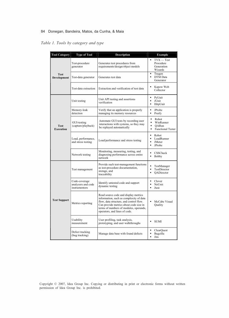
84 Donegan, Bandeira, Matos, da Cunha, & Maia
Copyright © 2007, Idea Group Inc. Copying or distributing in print or electronic forms without writtenpermission of Idea Group Inc. is prohibited.
Tool Category Type of Tool Description Example
Test-procedure generator
Generates test procedures from requirements/design/object models
� TYX — Test Procedure Generation Wizards
Test-data generator Generates test data � Tnsgen � DTM Data
Generator
Test Development
Test-data extraction Extraction and verification of test data � Kapow Web Collector
Unit testing Unit API testing and assertions verification
� PyUnit � JUnit � HttpUnit
Memory-leak detection
Verify that an application is properly managing its memory resources
� JProbe � Pruify
GUI-testing (capture/playback)
Automate GUI tests by recording user interactions with systems, so they may be replayed automatically
� Robot � WinRunner � QARun � Functional Tester
Load, performance, and stress testing Load/performance and stress testing
� Robot � LoadRunner � JMeter � JProbe
Test Execution
Network testing Monitoring, measuring, testing, and diagnosing performance across entire network
� CSSCheck � Bobby
Test management
Provide such test-management functions as test-procedure documentation, storage, and traceability
� TestManager � TestDirector � QADirector
Code-coverage analyzers and code instrumentors
Identify untested code and support dynamic testing
� Clover � NoUnit � Jtest
Metrics reporting
Read source code and display metrics information, such as complexity of data flow, data structure, and control flow. Can provide metrics about code size in terms of numbers of modules, operands, operators, and lines of code.
� McCabe Visual Quality
Usability measurement
User profiling, task analysis, prototyping, and user walkthroughs � SUMI
Test Support
Defect tracking (bug tracking) Manage data base with found defects
� ClearQuest � Bugzilla � Jira
Table 1. Tools by category and type

Automated Software Testing 85
Copyright © 2007, Idea Group Inc. Copying or distributing in print or electronic forms without writtenpermission of Idea Group Inc. is prohibited.
by statistical, algorithmic, or heuristic means. In statistical test-procedure genera-tion, the tool chooses input structures and values in a statistically randomdistribution, or a distribution that matches the usage profile of the software undertest (Dustin, 2002).
Most often, test-procedure generators employ action-, data-, logic-, event-, andstate-driven strategies. Each of these strategies is employed to probe for a differentkind of software defect. When generating test procedures by heuristic- or failure-directed means, the tool uses information provided by the test engineer. Failuresdiscovered frequently in the past by the test engineer are entered into the tool. Thetool then becomes knowledge-based, using the knowledge of historical failures togenerate test procedures.
• Test-data generators: Test-data generators aid the testing process by automati-cally generating test data. Many tools on the market support the generation of testdata and populating databases. Test-data generators can quickly populate adatabase based on a set of rules, whether data is needed for functional testing, data-driven load testing, or performance and stress testing.
• Test-data extraction tools: Using production data for testing purposes increasesthe integrity of testing by allowing testing teams to establish test scenarios usingreal test cases rather than relying on fabricated testing environments.
A test-data extraction tool minimizes time to create test data and maximizes integrityand usability of data.
Test-Execution Tools
• Unit-testing tools: This type of tool is used to program and execute tests in unitsof the developed application. The units are normally classes, methods, or flows.Generally a unit-testing tool supports only one development language.
• Memory-leak detection tools: These tools are used for a specific purpose: to verifythat an application is properly using its memory resources. These tools ascertainwhether an application is failing to release memory allocated to it, and provideruntime error detection. Since memory issues are involved in many programdefects, including performance problems, it is worthwhile to test an application’smemory usage frequently.
• GUI-testing tools (capture/playback tools): Many automated GUI testing tools areon the market. These tools usually include a record-and-playback feature, whichallows the test engineer to create (record), modify, and run (playback) automatedtests across many environments. Tools that record the GUI components at the user-interface control are most useful. The record activity captures the keystrokesentered by the test engineer, automatically creating a script in a high-level languagein the background. This recording is a computer program, referred to as a test script.Using only the capture and playback features of such a tool uses only about one-tenth of its capacity, however. To get the best value from a capture/playback tool,engineers should take advantage of the tool’s built-in scripting language.
86 Donegan, Bandeira, Matos, da Cunha, & Maia
Copyright © 2007, Idea Group Inc. Copying or distributing in print or electronic forms without writtenpermission of Idea Group Inc. is prohibited.
To create a reusable and maintainable test procedure, the test engineer must modifythe recorded script. The outcome of the script becomes the baseline test. The scriptcan then be played back on a new software build to compare its results to thebaseline. The results can be compared pixel-by-pixel, character-by-character, orproperty-by-property, depending on the test-comparison type, and the tool auto-matically pinpoints the difference between the expected and actual result (Dustin,2002).
• Load, performance, and stress testing tools: Performance-testing tools allow thetester to examine the response time and load capabilities of a system or application.The tools can be programmed to run on a number of client machines simultaneouslyto measure a client-server system’s response times when accessed by many usersat once. Stress testing involves running the client machines in high-stress sce-narios to determine whether and when they break.
• Network-testing tools: The popularity of applications operating in client/server orWeb environments introduces new complexity to the testing effort. The testengineer no longer exercises a single, closed application operating on a singlesystem, as in the past. Client-server architecture involves three separate compo-nents: the server, the client, and the network. Interplatform connectivity increasespotential for errors. As a result, the testing process must cover the performance ofthe server and the network, the overall system performance, and functionalityacross the three components (Dustin, 2002). Many network test tools allow the testengineer to monitor, measure, test, and diagnose performance across an entirenetwork.
Test-Support Tools
• Test-management tools: Test-management tools support the planning, manage-ment, and analysis of all aspects of the testing life cycle. Some test-managementtools, such as IBM’s Rational TestStudio, are integrated with requirement- andconfiguration-management and defect-tracking tools, in order to simplify the entiretesting life cycle.
• Code-coverage analyzers and code-instrumentors tools: Measuring structuralcoverage enables the development and test teams to gain insight into the effective-ness of tests and test suites. They are able to quantify the design complexities, helpproduce the integration tests, and measure the number of integration tests thathave not been executed. Some of them measure multiple levels of test coverage,including segment, branch, and conditional coverage.
• Metrics reporting tools: Tools responsible for reporting metrics analyze codecomplexity and identify application passages that offer a higher fault risk, reportingquality metrics. With these tools it is possible to know parts of code that have orhave not been tested.
The usage of metrics-reporting tools assures higher product quality, because it ispossible to have metrics showing the quality of what is being developed.
Automated Software Testing 87
Copyright © 2007, Idea Group Inc. Copying or distributing in print or electronic forms without writtenpermission of Idea Group Inc. is prohibited.
• Usability-measurement tools: Usability engineering is a discipline that includesuser-interface design, ergonomic concerns, human factors, graphics design, andindustrial and cognitive psychology. Usability testing is largely a manual processof determining the ease of use and other characteristics of a system’s interface(Dustin, 2002). However, some automated tools can assist with this process,although they should never replace human verification of the interface.
• Defect tracking (bug tracking): Most of the existing commercial tools present aconjunction of tool types or even categories. It may be a big advantage to obtainthese integrated tools. However in some cases not all functionalities are neededand the tools cost may be an inhibitor. Therefore, it is very important to analyze testtools’ costs and benefits thoroughly.
Some test tools are intrusive, because it may be necessary to insert special codeinto the application program so that the automated tool may work correctly,interacting with the testing tool. Development engineers may be reluctant toincorporate this extra code. They may fear it will cause the system to operateimproperly or require complicated adjustments to make it work properly. To avoidsuch conflicts, test engineers should involve the development staff in selecting anautomated tool and if the tool requires code additions (not all tools do), developersneed to know that well in advance.Intrusive tools pose the risk that defects introduced by testing hooks (codeinserted specifically to facilitate testing) and instrumentation could interfere withnormal functioning of the system.Besides, as with all technologies, test tools can be unpredictable. For example,repositories may become corrupt; baselines may not be restored, or may not alwaysbehave as expected. Often, much time must be spent tracking down a problem orrestoring a back-up of a corrupted repository. Test tools are also complex applica-tions in themselves, so they may have defects that interfere with the testing effort.
Programming Languages of Automated Test Tools
It has already been mentioned that there are a lot of test tools available on the market,and testing teams have used the tools and achieved great success. These test automationtools also include writing (i.e., coding) test scripts, which are software programs (Mosley& Posey, 2003). As such, they have their own programming languages and/or languageextensions that are required to accommodate software-testing events, such as Java(JUnit and JProbe) or Visual Basic; in one of the standard scripting languages such asPerl, CGI, or VB Script; or in the operating system’s command procedure language (Unix).The scripting language is usually embedded in a capture/playback tool that has anaccompanying source code editor. Some popular test tools write test scripts in VisualBasic 6.0 and execute the script in Visual Studio IDE. There is also literature thatintroduces how to write test scripts in Visual Basic 6.0 by hand. Some other tools arewritten in Java, such as JUnit, and JProbe and there are tools to write test scripts forsoftware products run on Unix, Linux, and other platforms.

88 Donegan, Bandeira, Matos, da Cunha, & Maia
Copyright © 2007, Idea Group Inc. Copying or distributing in print or electronic forms without writtenpermission of Idea Group Inc. is prohibited.
Test Tools Development
The usage of an automated tool will not always be adequate or provide necessarybenefits. Diversified factors may lead to the necessity of building a tool:
• Application incompatibility: The application may contain an element that willcause compatibility problems with any capture/playback tool on the market. If awork-around cannot be created, it may not be possible to use the capture/playbacktool. Even if a work-around can be created, it may not be worth the effort, being morebeneficial to create a customized tool.
• Operating system incompatibility: If there is a market absence of a tool, compatiblewith the various operation systems in use, there is no other choice than to considerbuilding a customized tool that will work in the specific environment under test.
• Specialized testing needs: In case the test tool cannot reach a critical/complexcomponent, an enhancement to the tool may be developed.
In case the organization chooses to develop a testing tool, resources, cost and time needto be determined, as well as management permission. The tools development must betreated as development effort of the project that demanded the use of the tool (Fewster& Graham, 1999). Many books provide detailed explanations of how to proceed todevelop a test tool inside an organization, such as Li and Wu (2004) and Fewster andGraham (1999).
Implantation of Test Automation
Many companies, certain of the advantages of test automation, want to define a processof test automation to enhance the software-testing process, but do not know how to doit. Next, some phases are described which may be used for the test-automation implan-tation.
Introduce Automated Test Ideas
In this stage, the expectations management related to test automation and explanationof its benefits are performed, introducing automated test ideas to the organization.Some imagine that a lot of time is spent with automation and that it has high costs.Therefore it is important to study its applicability (Donegan et al., 2005), verifyingmanagement, financial and structural benefits and risks involved, because the advan-tages and disadvantages of automation are to be made clear for everyone. At this moment,those involved with the implantation, including internal investors, are supposed to beconscious that normally the return on investment will be obtained in a medium or long
Automated Software Testing 89
Copyright © 2007, Idea Group Inc. Copying or distributing in print or electronic forms without writtenpermission of Idea Group Inc. is prohibited.
term, since test automation does not reduce testing time as soon as it is introduced. Thisoccurs given to time spent with tools initial learning, adaptation to the new testingprocess, among other factors mentioned before.Generally, introducing tests automation requires a lot of investment. That does nothappen only with the acquisition of a tool, but also with professional preparation ofstakeholders and with maintenance of existent hardware to support the one beinginstalled. Those variables must be considered in the projects’ budget.In this stage, an open communication with high management is fundamental, beingconstantly informed of organizational risks already detected, as well as direct benefitsof automation, so that they may support the entire automation process even being awareof the existent challenges.It is important to form a team with specialized professionals to begin the implantation oftests automation. The team must have at least one representative with knowledge of theorganizational culture. These professionals will also be responsible for conducting thenext stage.After taking into account all the factors mentioned, the organization might take thedecision of beginning test automation, or may abort the idea, being aware of risks andbenefits involved. In case the decision is positive, some of the initial automated test ideasabove have to be detailed in a tests automation plan, defining tasks that will be executed.
Choose Test Tool
This stage guides the choice and evaluation of necessary tools for test automation.Initially, the requirements of the tool are researched, according to organizationalnecessities: available resources, architecture of developed applications, platforms used,automation tool language, type and stage of desired test, and others. If possible,requirements should be prioritized conforming to the level of importance, making itpossible to focus on key requirements in the evaluation process.According to the requirements of highest importance, available tools in the market areselected. In case there is not any tool accessible to provide the organizational needs, thepossibility of developing a homemade tool must be taken into account, which was seenearlier on in the chapter.However, generally, a single test tool will not fulfill all the automated testing requirementsfor an organization, unless that organization works only with one type of operatingsystem and one type of application. Expectations must be managed. It must be made clearthat currently there is not a single tool on the market that is compatible with all operatingsystems and programming languages. This is only one reason why several tools arerequired to test the various technologies.After preselecting the tools, there must be an assurance that the tools will fulfill therequirements and other points, like usability and performance. A way of doing this isusing demo versions or doing hands-on. As a consequence, one or more tools areselected, according to company needs.

90 Donegan, Bandeira, Matos, da Cunha, & Maia
Copyright © 2007, Idea Group Inc. Copying or distributing in print or electronic forms without writtenpermission of Idea Group Inc. is prohibited.
Refine Testing Process
This stage sketches the refinement of the organizational test process, including neces-sary activities for automated tests.As an aftermath of the test tools choice, the process of implantation of automationbegins. Now it is necessary to lay out objectives and strategies, by means of commonarchitectures used in organizational projects. The strategy for automation in a companymust contemplate directives that increase codification use and decrease their mainte-nance. See the “Good Practices” section.After establishing these aspects, automation activities are defined. These activities areincorporated into the organizational testing process and stakeholders need to beproperly trained. The mainly affected stakeholders are investigated, and a definition ofthe course goals (such as time and scope) is made.A good way to consolidate the test process and chosen tools is to define a project to beautomated and tested, called pilot project, applying the new test process and tools. It isnecessary to monitor process planning, test-case elaboration, code creation, and testsexecution and, especially, the results must be evaluated (Molinari, 2003).All those involved in the test automation must participate, so that pertinent directivesto the organizational context may be outlined and so that their commitment with the“Automation Product” is assured.
Develop Test Automation
Test Automation Planning
Conducting a common process of a Test Plan and designing test automation characterizethe planning stage.For the Test Plan, the scope of automation is defined and involved risks of the projectin question are investigated, analyzed, and qualified. Besides, a test-automation strategymust be defined to orientate execution and monitoring, based on factors such as testscope, reuse of code, maintenance effort, and availability of time and resources.Conventions of suites and code nomination may be established, as well as logicalgrouping relevant to worked scope. The most complex groups have to be identified anddescribed in detail.Test cases must have a well-defined design as they provide relevant information aboutthe system to be tested without considering if tests are manual or automated. These testcases have to be analyzed, in order to identify the best automation possibilities. At thispoint, the test analyst must have a good understanding of how to raise valuableautomation opportunities, in other words, opportunities that bring great aggregatevalue.
Automated Software Testing 91
Copyright © 2007, Idea Group Inc. Copying or distributing in print or electronic forms without writtenpermission of Idea Group Inc. is prohibited.
In case of automation of functional tests, another step consists of planning anddesigning useful test data, identifying the best way to communicate with code. See“Automation Techniques” section.
Test Automation Execution
Test execution approaches installation and configuration of tool and environment toinitiate tests. This environment must also consider performance tests, which use variousstations or virtual users. All necessary information concerning the environment must becontained in the test plan.The preparation of a manual with instructions concerning chosen tools, test designinformation and adopted conventions is relevant.The test team must develop test code based on the premises established during theplanning stage and on the test projects already developed. The codes must be simple,robust, maintainable and, if possible, reusable.After the test codes have been developed, unit, integrated and systemic tests can beperformed. Generally, a different team of the one that executes systemic tests executesunit and integrated tests.Each test team must report detected errors during test execution (integrated and systemictests). A tool to report bugs facilitates this step.
Test Automation Management
Now that the tests are already planned and executed, they need to be managed. Controlis essential for the test automation evolution analysis, with the perspective of analyzingif the new form of performing tests is acceptable and adaptable. Automation managementis also fundamental to identify some points adopted during the planning stage that needto be adjusted, or even to reevaluate the tool with the purpose of certifying usability inthe organization’s context.Tests codification must be constantly monitored, so that it can be a reflex of theapplication in such a way that modifications made in the product during its life cycle canalso be contemplated in test code. This activity prevents reporting errors to thedevelopment team, caused by failure of test codification.For systemic tests automation, when errors are found, it is necessary to do an analysisof them before sending the report to the development team, filtering duplicities and fakebugs, which are bugs caused by errors made during codification of tests.
Evaluate and Improve Test Automation
Automated test activities evaluation must be made during the whole test life cycle, sothat improvements may be implanted. These enhancements can be observed along with
92 Donegan, Bandeira, Matos, da Cunha, & Maia
Copyright © 2007, Idea Group Inc. Copying or distributing in print or electronic forms without writtenpermission of Idea Group Inc. is prohibited.
execution of automated tests in organizational projects. Many of them are incorporatedpunctually into projects. The company is, therefore, responsible for collecting, evaluat-ing, and incorporating the improvements to the organizational process, when it is thecase. Afterwards, stakeholders must be informed of changes made to the process and,if necessary, be trained.Another important point is the test tool performance evaluation and determining whatcan be done to enhance it in the next project or test cycle.
Related Works
There are many works related to test automation: reports and case studies of organiza-tions that have implemented automated software tests; research projects published indiverse events and magazines, creating models for test automation, elaborating efficienttechniques for different types of automated tests, as well as others.Organizations that develop software are constantly automating their tests to improveprocess and product quality, there are many examples to be found nowadays, here aretwo specific organizations using automated tests: Instituto Atlântico and BMC Software.Instituto Atlântico implanted automation of functional system tests initially in a pilotproject and, nowadays, automated tests are being used in other projects of the organi-zation. Time spent to develop automated use case tests sometimes is superior to the timenecessary to test it manually. However, Instituto Atlântico uses regression tests and thiseconomizes time to execute tests, recovering the amount of time already used withcodification after some increments. The tools used are those from Rational IBM: Robot,Test Manager and, more recently, Functional Tester. More details can be read in Doneganet. al (2005).BMC Software developed a system to automate tests of a products suite called BMC’sMetaSuite — family of applications client/server. They formulated orientations tochoose people to automate tests and what should be automated.BMC uses the tool QA Partner. One of the main gains using this tool is the easymaintenance of test scripts. Test cases are implemented before the interface is completelyready, because the test cases are independent of implementation details. In a week, BMCexecuted around three times each test case of three suite products. And those tests couldbe amply repeated in a more consistent manner. More information can be found inPettichord (2001).There are some interesting publications following, related to test automation, providingnew approaches to automation. They may be adopted by organizations, if they are inconformity with objectives and purposes of the organization or specific project usingautomated tests.

Automated Software Testing 93
Copyright © 2007, Idea Group Inc. Copying or distributing in print or electronic forms without writtenpermission of Idea Group Inc. is prohibited.
Interface-Driven Model-Based Test Automation
The paper describes an interface-driven approach that combines requirement modelingto support automated test case and test driver generation. It focuses on how testengineers can develop more reusable models by clarifying textual requirements as modelsin terms of component or system interfaces. The focus of interface-driven modeling hasbeen recognized as an improvement over the process of requirement-driven model-basedtest automation (Blackburn, Chandramouli, Busser, & Nauman, 2002).
Model-Based Approach to Security Test Automation
The paper summarizes the results of applying a model-based approach to automatesecurity functional testing. The approach involves developing models of securityfunction specifications (SFS) as the basis for automatic test-vector and test-drivergeneration (Blackburn, Busser, & Nauman, 2002).
Further Reading
A very good place to do some further reading is in the Web site http://www.stickyminds.com. You can find every kind of papers related to software tests,including some very interesting related to automated software testingIn terms of tools to automate tests, if you are interested in more examples of existent tools,we advise you to access Brian Marick’s website http://www.testingfaqs.org (Marick,2005). He presents an extensive list of tools for some types of automated tests. To learnmore about the development of a tool to automate tests, it is interesting to read “EffectiveSoftware Test Automation — Developing an Automated Software Testing Tool” (Li,2004), a book that teaches how to build a fully automated testing tool and provides expertguidance on deploying it in ways reaching high benefits.In the section “Implantation of Test Automation” we showed a brief methodology toautomate tests in an organization, however if you desire some further readings, it isinteresting to read about the automate testing life-cycle methodology (ATLM) byDustin, Rashka, and Paul (1999).
Conclusion
Good planning, clear definition of roles of those involved with automated tests, adequatetools and implantation with strong management to control risks and costs are essentialso that the automated tests are successful in an organization.

94 Donegan, Bandeira, Matos, da Cunha, & Maia
Copyright © 2007, Idea Group Inc. Copying or distributing in print or electronic forms without writtenpermission of Idea Group Inc. is prohibited.
Risks and benefits involved with automation need to be researched and afterwardsinformed to all stakeholders involved, especially to the high management, so that thereis an effective compromise. Nevertheless, results obtained during test automation alsohave to be disclosed.Automated tests are capable of increasing test coverage; because of time gain, costsubsided by future problems, and increase of the application’s stability and investorstrust.A methodology for implantation of test automation was explained in this chapter,suggesting test automation to be implanted in stages, beginning with the decision ofautomation until process improvement, facilitating an efficient management and controlof the automation process. An important stage for test automation is the choice of toolsto be used. To make the right choice it is important to know the organization’s real needs,testing-process maturity, test-team experience, automation techniques, and advantagesand disadvantages of available commercial tools.When initiating test automation it is important to customize the organizational testprocess according to required activities necessary for automated tests, training profes-sionals, preparing environment, among other aspects given along the chapter. Thus itis possible to perceive that test automation must be treated as a project, requiring a plan,activities execution, and results monitoring. Therefore, it is more likely to obtain apositive return for the organization.
References
Blackburn, M., Busser, R., & Nauman, A. (2002). Interface-driven model-based testautomation — Starwest 2002. Retrieved September 2, 2005, from http://www.software.org/pub/externalpapers/starwest_2002.pdf
Blackburn, M., Chandramouli, R., Busser, R., & Nauman, A. (2002). Interface-drivenmodel-based test automation — Quality Week 2002. Retrieved September 2, 2005,from http://www.software.org/pub/externalpapers/blackburn_issre_2002.pdf
Boehm, B. (1981). Software engineering economics. Englewood Cliffs, NJ: Prentice Hall.Donegan, P., Bandeira, L., Matos, A., Cunha, P., Maia, C., & Pires, G. (2005) Aplicabilidade
da automação de testes funcionais — a experiência no instituto atlântico. InSimpósio brasileiro de qualidade de software (pp. 447-454). Porto Alegre: PontifíciaUniversidade Católica do Rio Grande do Sul.
Dustin, E. (2002). Effective software testing: 50 specific ways to improve your testing.Boston: Pearson Education.
Dustin, E., Rashka, J., & Paul, J. (1999). Automated software testing: Introduction,management, and performance. Boston: Addison Wesley.
Fantinato, M., Cunha, A., Dias, S., Mizuno, S., & Cunha, C. (2004). AutoTest — Umframework reutilizável para a automação de teste funcional de software. In Anais

Automated Software Testing 95
Copyright © 2007, Idea Group Inc. Copying or distributing in print or electronic forms without writtenpermission of Idea Group Inc. is prohibited.
SBQS — Simpósio brasileiro de qualidade de software (pp. 286-300). Brasília,Brazil: Universidade católica de Brasília.
Fewster, M., & Graham, D. (1999). Software test automation: Effective use of testexecution tools. Boston: Addison Wesley.
Kaner, C., Bach, J., & Pettichord, B. (2002). lessons learned in software testing: A context-driven approach. New York: John Wiley & Sons.
Karner, G. (1993). Metrics for objectory. Unpublished diploma thesis, University ofLinköping, Sweden.
Li, K., & Wu, M. (2004). Effective software test automation: Developing an Automatedsoftware testing tool. Alamdea, CA: Sybex.
Marick, B. (2005). Testingfaqs.org — An information resource for software testers.Retrieved September 2, 2005, from http://testingfaqs.org
McGraw, G., & Michael, C. (1996, July). Automatic generation of test-cases for softwaretesting. In CogSci 1996, Proceedings of the 18th Annual Conference of theCognitive Science Society (pp. 370-375). Mahwah, NJ: Lawrence Erlbaum.
Molinari, L. (2003). Testes de software — produzindo sistemas melhores e mais confiáveis.São Paulo, Brazil: Ed. Erica.
Mosley, D., & Posey, B. (2003). Just enough software test automation. New York:Yourdon Press Series, Prentice Hall.
Myers, G. (2004). The art of software testing. New York: John Wiley & Sons.Pettichord, B. (2001). Success with test automation. Revised version of a Quality Week
paper. San Francisco. Retrieved September 02, 2005, from http://www.io.com/~wazmo/succpap.htm
Rios, E., & Moreira, T. (2003). Projeto & engenharia de software — testes de software.Rio de Janeiro, Brazil: Atlas Book.

96 Neto, Perkusich, de Almeida, & Perkusich
Copyright © 2007, Idea Group Inc. Copying or distributing in print or electronic forms without writtenpermission of Idea Group Inc. is prohibited.
Chapter V
A Formal Verificationand ValidationApproach for
Real-Time DatabasesPedro Fernandes Ribeiro Neto,
Universidade do Estado do Rio Grande do Norte, Brazil
Maria Lígia Barbosa Perkusich,Universidade Católica de Pernambuco, Brazil
Hyggo Oliveira de Almeida,Federal University of Campina Grande, Brazil
Angelo Perkusich,Federal University of Campina Grande, Brazil
Abstract
Real-time database-management systems provide efficient support for applicationswith data and transactions that have temporal constraints, such as industrialautomation, aviation, and sensor networks, among others. Many issues in real-timedatabases have brought interest to research in this area, such as: concurrence controlmechanisms, scheduling policy, and quality of services management. However,considering the complexity of these applications, it is of fundamental importance toconceive formal verification and validation techniques for real-time database systems.

A Formal Verification and Validation Approach for Real-Time Databases 97
Copyright © 2007, Idea Group Inc. Copying or distributing in print or electronic forms without writtenpermission of Idea Group Inc. is prohibited.
This chapter presents a formal verification and validation method for real-timedatabases. Such a method can be applied to database systems developed for computerintegrated manufacturing, stock exchange, network-management, and command-and-control applications and multimedia systems. In this chapter, we describe a case studythat considers sensor networks.
Introduction
Nowadays, the heterogeneity of platforms, distributed execution, real-time constraints,and other features are increasingly making software development a more complexactivity. Besides, the amount of data to be managed is increasing as well. Taken together,complexity and data management are causing both risk and cost of software projects toget higher.Database management systems are used to manage and store large amounts of dataefficiently. However, when both data and transactions have timing restrictions, real-timedatabases (RTDB) are required to deal with real-time constraints (Ribeiro-Neto, Perkusich,& Perkusich, 2004). For an RTDB, the goal is to complete transactions on time, whilemaintaining logical and temporal consistency of the data. For real-time systems, correctsystem functionality depends on logical as well as on temporal correctness. Staticanalysis alone is not sufficient to verify the temporal behavior of real-time systems. Tosatisfy logical and temporal consistency, concurrency control techniques and time-cognizant transactions processing can be used, respectively. The last occurs by tailoringtransaction management techniques to explicitly deal with time.The real-time ability defines nonfunctional requirements of the system that must beconsidered during the software development. The quality assurance of real-time systemsis necessary to assure that the real-time ability has been correctly specified. Imprecisecomputation is used as a technique for real-time systems where precise outputs aretraded off for timely responses to system events. For that, formal models can be createdto verify the requirement specifications, including the real-time specifications (Ribeiro-Neto, Perkusich, & Perkusich, 2003).Validation as well as verification can be carried out by simulation model. With thesimulation model, a random sample will be selected from the input domain of the testobject, which is then simulated with these chosen input values. After that, the resultsobtained by this execution are compared with the expected values. Thus, a simulationmodel is as a dynamic technique, that is a technique that contains the execution of thetest object. One major objective of simulation models is error detection (Herrmann, 2001).The main motivation for this research is the fact that methods to describe conceptualmodels of conventional database systems cannot be directly applied to describe modelsof real-time database systems. It occurs because these models do not provide mecha-nisms to represent temporal restrictions that are inherent to real-time systems. Also, mostof the available models focus on the representation of static properties of the data. Onthe other hand, complex systems, such as real-time databases, also require the modelingof dynamic properties for data and information. Therefore, the development of methods

98 Neto, Perkusich, de Almeida, & Perkusich
Copyright © 2007, Idea Group Inc. Copying or distributing in print or electronic forms without writtenpermission of Idea Group Inc. is prohibited.
to design real-time databases with support for both static and dynamic modeling is animportant issue.In the literature, there are few works for real-time database modeling that allow a formalanalysis, considering verification and validation characteristics. The existing tools forsupporting modeling process especially do not present simulation capacity. The unifiedmodeling language (UML) approach presents a number of favorable characteristics formodeling complex real-time systems, as described in Selic and Rumbaugh (1998) andDouglass (2004). UML also is used for modeling object-oriented database systems.However, the existing tools for UML modeling do not present simulation capacity.This chapter describes a formal approach to verify and validate real-time databasesystems. The approach consists of the application of the five steps: (1) building an objectmodel; (2) building a process model; (3) generating an occurrence graph; (4) generatinga message-sequence chart; and (5) generating a timing diagram. The two first stepsinclude static and dynamic analysis, respectively. The following steps allow the user tovalidate the model. Hierarchical coloured Petri nets (HCPNs) are used as the formallanguage to describe RTDB models (Jensen, 1998). The proposed approach can beapplied to different domains, such as computer-integrated manufacturing, stock ex-changes, network management, command-and-control applications, multimedia sys-tems, sensor networks, and navigation systems. In this chapter, we describe a case studyconsidering sensor networks. Sensor networks are used to control and to monitor thephysical environment and sensor nodes may have different physical sensors and can beused for different application scenarios.The remainder of this chapter is presented as follows. First, a background is presented,to ease the comprehension of approach. Concepts about RTDB, quality of services andHCPNs are defined. Second, the formal verification and validation approach for real-timedatabases is described as well as a sensor network case study. Third, future trends arepresented. Finally, conclusions are presented.
Background
Real-Time Databases (RTDB)
The real-time database-management systems must provide the characteristics of con-ventional databases besides assuring that the real-time constraints are imposed on boththe data and transactions. These constraints arise in applications where the transactionsmust meet deadlines.The amount of applications that benefit from the utilization of RTDB is increasing as well.This increase is a consequence of the proliferation of embedded systems that includesboth systems that are similar to those present in personal computers and smaller systemswith a minimal memory and calculator capacity, such as those present in mobile devices.An RTDB is required when: The volume of data is large; responses depend on multiplevalues; responses to aperiodic events are required; and there are constrained timing

A Formal Verification and Validation Approach for Real-Time Databases 99
Copyright © 2007, Idea Group Inc. Copying or distributing in print or electronic forms without writtenpermission of Idea Group Inc. is prohibited.
requirements. The correctness in real-time databases implies: satisfying all usual consis-tency constraints; executing transactions within timing constraints; and satisfyingtemporal consistency of the data. The real-time data and transactions are also defined.The data items reflect the state of the environment. The transactions are classified withrespect to their deadlines, such as hard, soft, or firm; arrival-pattern — periodic,aperiodic, sporadic; and data-access-pattern — read-only, write-only and update. InFigure 1, a schema illustrating the properties of the RTDB is shown.
Data Properties
The data correctness in RTDB is assured by logical and temporal consistency. The real-time data can be classified into static and dynamic. The correctness of static data isguaranteed by the logical consistency, since is has not become outdated. The dynamicdata may change continuously to reflect the real-world state, such as object positions,physic measure, stock market, and so on. Each dynamic datum has a timestamp of thelatest update and the data can be divided into base data and derived data. A deriveddatum can be derived from various base data (Kang, 2001).The external consistency of dynamic data is defined using validity intervals to assurethe consistency between the state represented by the database content and the actualstate of environment. The validity intervals are of two types as follows (Kang, 2001):
• Absolute validity interval (avi) is defined between the environment state and thevalue reflected in the database. The data x is considered temporally inconsistentif (now - timestamp(x) > avi(x)), where now is the actual time of system, timestampis the time of the latest update of data.
Figure 1. Real-time database systems
� Data management� Transaction support� Concurrency control� Query processing
Traditional database systems
� Scheduling algorithms� Imprecise computation� Priority assigment� Resource reservation
Real-time systems
Real-time database systems

100 Neto, Perkusich, de Almeida, & Perkusich
Copyright © 2007, Idea Group Inc. Copying or distributing in print or electronic forms without writtenpermission of Idea Group Inc. is prohibited.
• Relative validity interval (rvi) is defined among the data used to derive other data.Consider a data item y is derived from a data set R={x1,x2,...,xk}. y is temporallyconsistent if the if the data in R that the compose are temporally valid and the|timestamp(xi • R) - timestamp(xj 0 R) | ≤ rvi(y). This measure arises to producederived data from data with the approximate time.
The dynamic data are represented by x:(value,avi,timestamp) and will be temporallyconsistent. If both absolute and relative validity interval are satisfied. Consider theexample where a data item t, with avi(t)=5, reflect the current temperature and the dataitem p represent the pressure with avi(p)=10. The data item y is derived from data setR={t,p} and have relative validity interval rvi(y)=2. If the actual time is 50, then (a)t:(25,5,45) and p:(40,10,47) are temporally consistent because as absolute validityinterval as relative validity interval is valid. But, (b) t:(25,5,45) and p:(40,10,42) are nottemporally consistent, because only the absolute validity interval is assured.
Transaction Properties
The real-time transactions are characterized along three dimensions based on the natureof transactions in real-time database systems: the nature of real-time constraints, thearrival pattern, and the data-access type.
• Real-time constraints: The real-time constraints of transactions are related to theeffect of missing its deadline and can be categorized in hard, firm and soft. Harddeadlines are those that may result in a catastrophe if the deadline is missed. Theseare typically critical systems, such as a command delayed to stop a train causinga collision.To complete a transaction with a soft deadline after its time constraint is undesir-able. However, soft deadlines missed can commit the system performance. Thetransactions with firm deadline will be aborted if its temporal constraints are lost.
• Arrival pattern of transactions: The arrival pattern of transactions refers to timeinterval of execution. Generally, the transactions are periodically executed in real-time databases, since they are used to record the device reading associated to theenvironment or to manipulate system events. The arrival pattern can be aperiodic,where there is not a regular time interval between the executions of transactions.The transactions also can execute in random time. However, there is a minimal timeinterval between the executions of transactions.
• Data access type: In relation to data access, the transactions are categorized as:write transactions (or sensors), update transactions, and read transactions. Thewrite transactions obtain the state of the environment and write into the database.The update transactions derive new data and store them in the database. Finally,the read transactions read data from database and send them.
A Formal Verification and Validation Approach for Real-Time Databases 101
Copyright © 2007, Idea Group Inc. Copying or distributing in print or electronic forms without writtenpermission of Idea Group Inc. is prohibited.
In the database, it is necessary to guarantee the same views, of the same data item, fordifferent transactions. This property is called internal consistency and is assured by theACID properties. ACID is an acronym for atomicity, consistency, isolation, and dura-bility. These properties are defined for a real-time database as follows:
• Atomicity: Is applied for subtransactions, where a subtransaction must be wholeexecuted or neither step must be considered of them.
• Consistency: The transaction execution must always change the consistent stateof a database in another consistent state. An imprecision limited in the internalconsistency can be permitted in order to meet the temporal constraints of transac-tions.
• Isolation: The actions of a transaction can be visible by other transactions beforeit commits.
• Durability: The actions of a transaction need not be persistent, since both data andtransactions have temporal validity.
Concurrency Control
The negotiation between logical and temporal consistency, a concurrency-controltechnique should be capable of using knowledge about the application to determinewhich transactions can be executed concurrently. Such a technique, named semanticconcurrency control, allows increasing the concurrent execution of transactions (methodinvocation). Based on the knowledge of the application the designer must define whichtransactions may be concurrently executed and when. Defining compatibilities betweenthe executions of the transactions does this. Therefore, this technique allows relaxingthe ACID properties.Transactions in real-time do not need to be serialized, especially updated transactionsthat record information from the environment. However, the consequence of relaxingserialization is that some imprecision can be accumulated in the database, and in thevision of the database.An object-oriented semantic concurrency control technique, described in DiPippo(1995), named semantic-lock technique, allows logical and temporal consistency of thedata and transactions and allows the negotiation among them. The technique also allowsthe control of the imprecision resulting from the negotiation. The concurrency controlis distributed among the objects, and a compatibility function, says CF for short, isdefined for each pair of methods for database objects. CF is defined as follows:
CF(mati ,minv) = Boolean Expression → IA
where mati represents the method that is being executed and, minv represents the methodthat was invoked. The Boolean Expression can be defined based on predicates involvingvalues of the arguments of the methods, the database attributes, and the system in
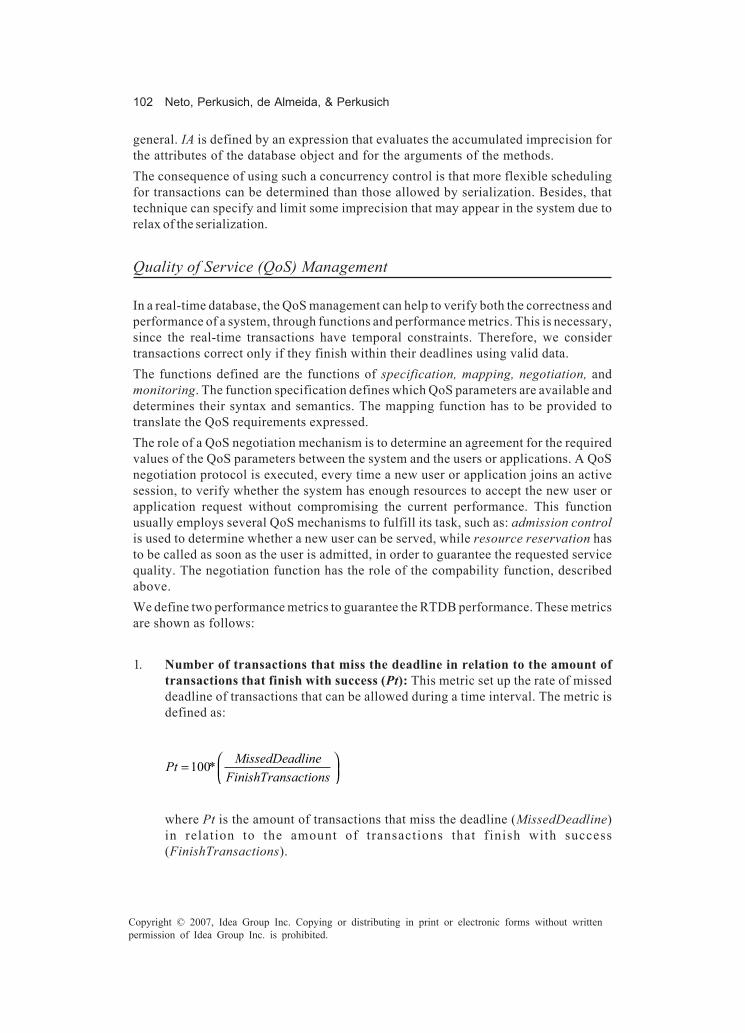
102 Neto, Perkusich, de Almeida, & Perkusich
Copyright © 2007, Idea Group Inc. Copying or distributing in print or electronic forms without writtenpermission of Idea Group Inc. is prohibited.
general. IA is defined by an expression that evaluates the accumulated imprecision forthe attributes of the database object and for the arguments of the methods.The consequence of using such a concurrency control is that more flexible schedulingfor transactions can be determined than those allowed by serialization. Besides, thattechnique can specify and limit some imprecision that may appear in the system due torelax of the serialization.
Quality of Service (QoS) Management
In a real-time database, the QoS management can help to verify both the correctness andperformance of a system, through functions and performance metrics. This is necessary,since the real-time transactions have temporal constraints. Therefore, we considertransactions correct only if they finish within their deadlines using valid data.The functions defined are the functions of specification, mapping, negotiation, andmonitoring. The function specification defines which QoS parameters are available anddetermines their syntax and semantics. The mapping function has to be provided totranslate the QoS requirements expressed.The role of a QoS negotiation mechanism is to determine an agreement for the requiredvalues of the QoS parameters between the system and the users or applications. A QoSnegotiation protocol is executed, every time a new user or application joins an activesession, to verify whether the system has enough resources to accept the new user orapplication request without compromising the current performance. This functionusually employs several QoS mechanisms to fulfill its task, such as: admission controlis used to determine whether a new user can be served, while resource reservation hasto be called as soon as the user is admitted, in order to guarantee the requested servicequality. The negotiation function has the role of the compability function, describedabove.We define two performance metrics to guarantee the RTDB performance. These metricsare shown as follows:
1. Number of transactions that miss the deadline in relation to the amount oftransactions that finish with success (Pt): This metric set up the rate of misseddeadline of transactions that can be allowed during a time interval. The metric isdefined as:
100 = MissedDeadlinePt *
FinishTransactions
where Pt is the amount of transactions that miss the deadline (MissedDeadline)in relation to the amount of transactions that finish with success(FinishTransactions).

A Formal Verification and Validation Approach for Real-Time Databases 103
Copyright © 2007, Idea Group Inc. Copying or distributing in print or electronic forms without writtenpermission of Idea Group Inc. is prohibited.
2. Upper imprecision of data (Impr): Is the threshold of imprecision admitted in thedata item for it to be considered logically valid. Impr is defined as:
*100
= ImpImpr CurrentValue
where CurrentValue is the value of data item stored in database and Imp is the indexof amount of imprecision admitted.
HCPN-Based Modeling
Hierarchical Coloured Petri Nets
Hierarchical coloured Petri nets (HCPNs) are an extension of coloured Petri nets (CPNs)(Jensen, 1998) and are a suitable modeling language for verifying systems, as they canexpress concurrency, parallelism, nondeterminism, and different levels of abstraction.In Figure 2, a Petri net is illustrated, where hierarchical levels are allowed. Thesehierarchical levels are possible due to the inclusion of two mechanisms: substitutiontransitions and fusion places. A substitution transition is a transition that will bereplaced by a CPN page. The page to which the substitution transition belongs is calleda superpage and the page represented by the transition is called the subpage. Theassociation between subpages and superpages is performed by means of sockets andports.
Figure 2. Coloured Petri net
Sub-page
Super-page
Input Port
Output Port
Socket
Socket
Substitution Transition
FusionPlace
FusionPlace

104 Neto, Perkusich, de Almeida, & Perkusich
Copyright © 2007, Idea Group Inc. Copying or distributing in print or electronic forms without writtenpermission of Idea Group Inc. is prohibited.
Sockets are all the input and output places of the transition in the superpage. Ports arethe places in the subpage associated to the sockets. The ports can be input, output, orinput-output. For simulation and state, space-generation sockets and ports are gluedtogether and the resulting model is a flat CPN model. The fusion places are physicallydifferent but logically only one forming a fusion set. Therefore, all the places belongingto a fusion set have always the same marking. A marking of a place is the set of tokensin that place in a given moment. The marking of a net is the set of markings of all placesin the net at a given moment (Jensen, 1998).Indeed, these two additional mechanisms, substitution transitions and fusion places, areonly graphical, helping in the organization and visualization of a CPN model. They favorthe modeling of larger and more complex systems by giving the designer the ability tomodel by abstraction, specialization, or both.
Design/CPN Tools
Design/CPN (Jensen et al.,1999) is a tool package supporting the use of HCPN. TheDesign/CPN tool has four integrated parts:
1. The CPN editor supports construction, modification, and syntax check of CPNmodels.
2. The CPN simulator supports interactive and automatic simulation of CPN models.3. The occurrence graph tool supports construction and analysis of occurrence
graphs for CPN models (also known as state spaces or reachability graphs/trees).4. The perfomance tool supports simulation=based performance analysis of CPN
models.
The design/CPN package is one of the most used Petri net tools. Design/CPN supportsCPN models with complex data types (colour sets) and complex data manipulations (arcexpressions and guards), both specified in the functional programming language Stan-dard ML(Jensen et al., 1999).
Real-Time DatabaseVerification and Validation Method
The formal verification and validation method for real-time database systems consistsof the application of the following steps, as illustrated in Figure 3, which are detailed inthis section:

A Formal Verification and Validation Approach for Real-Time Databases 105
Copyright © 2007, Idea Group Inc. Copying or distributing in print or electronic forms without writtenpermission of Idea Group Inc. is prohibited.
1. Build an object model: It is used to specify the requirements and identify the maincomponents of the system. It is also used to model static properties of objects, suchas attributes, operations, and logical and timing constraints. In any way, the objectmodel defines the discourse universe to the process model.
2. Build a process model: It is used to model both functional and dynamic propertiesof objects. The functional properties define the object operations, while thedynamic property represents the temporal interactions of objects and its answersto the events. The process model is composed of the operations identified in theobject model.
3. Generate an occurrence graph: It is a representation of the state space of the HCPNmodel.
4. Generate a message sequence chart: They are generated for each scenario,considering a possible execution sequence.
5. Generate a timing diagram: It is a diagram to show the timing constraints in timesample.
Build an Object Model
In the object model each object is a unique entity. Objects with the same data structure(attributes) and behavior (operations), in the context of the particular application
Figure 3. Real-time database verification and validation method
1 2 3
45
ProcessModel
ObjectModel
Simulation
Model
Verification
Validation
Requirement
OccurrenceGraph
MessageSequence Chart
TimingDiagram
3
2
1
03 6 9 12 15 18 21 24

106 Neto, Perkusich, de Almeida, & Perkusich
Copyright © 2007, Idea Group Inc. Copying or distributing in print or electronic forms without writtenpermission of Idea Group Inc. is prohibited.
environment are grouped into an object class. Classes can be grouped in a hierarchicalstructure. Classes may have attributes; the attributes are structural properties of classesthat can have both logical and temporal constraints; the relationships are the linksbetween the classes; the operations are functions or procedures applicable to the classattributes, and the method is the implementation of an operation (Rumbaugh, Blaha,Premerlani, Eddy, & Lorensen, 1991).The object model consists of a set of: class diagram, object diagram, and datadictionary. The class diagrams have shown the general description of the system, whilethe object diagrams shown object instances. The data dictionary defines whole entitiesmodeled (class, associations, attributes, operations).The object model begins with the problem declaration analysis and has the followingsteps:
1. Identification of the objects: The external actors and objects that interact with thesystem are identified as the problem context. Elements of the object model thatemerge from the analysis of the real problem are directly mapped into logicalobjects. Each instance of an object is assumed to be unique. The objects in an objectclass have a unique identity that separates and identifies them from all other objectinstances.
2. Identification of relationships among objects: A conceptual relationship amonginstances of classes. Associations have cardinality including one-to-one, one-to-many, and many-to-many. Most object-oriented texts do not address the natureof an association (i.e., mandatory or optional), except in the definition of the objectbehavior.
3. Addition of attributes to objects: a data value that can be held by the objects in aclass. Attributes may be assigned to different data types (e.g., integer).
4. Use of generalizations to observe similarities and differences: the essentialcharacteristics of an object or class, ignoring irrelevant features, providing crisplydefined conceptual boundaries. This maintains a focus upon identifying commoncharacteristics among what may initially appear to be different objects. Abstractionenhances reusability and inheritance.
5. Identification of operations: the direct manipulation of an object, categorized as:Constructor: create an object and/or initialize. Destructor: free the state of anobject and/or destroy the object. Modifier: alter the state of the object. Selector:access and read the state of an object. Iterator: access all parts of an object in awell-defined order.
6. Identification of concurrent operations: In this step, the designer analyzes thesystem to discover which operations need to be executed concurrently and in thatcondition this occurs. In follow, it is defined the function that details the situationswhich the operations can be executed concurrently.
7. Identification of both logical and temporal constraints: The designer must declareboth logical and temporal constraints to objects. These constraints define thecorrect states of each object. Thus, the constraints are defined as predicates that

A Formal Verification and Validation Approach for Real-Time Databases 107
Copyright © 2007, Idea Group Inc. Copying or distributing in print or electronic forms without writtenpermission of Idea Group Inc. is prohibited.
include the attributes value, time, and so on. For instance, the absolute validityinterval defined to real-time data, in the Background section, expresses a temporalconstraint to data objects.
Build a Process Model
The process model captures both functional and dynamic properties of objects. Thismodel is used in the analysis, design, and implementation phases of the software-development life cycle. These phases can be tackled concurrently, using hierarchicalcoloured Petri nets. HCPNs are used to analyze the system behavior. In this model, theobjects are described through HCPN modules (or pages) that are defined from objectmodels. Then, for each object that contains operations identified in the model, a HCPNmodule is created, where the correspondent operations are modeled. We use the design/CPN tool package (Jensen et al., 1999) for HCPN modeling. For that, the following stepsmust be performed:
1. Identification of the objects in HCPN: In this step, all of the objects in the objectmodel are identified, and for each object identified an HCPN module is constructed.
2. Identification of functions for each object: The operations that must be executedby each object are identified. What each object must execute is analyzed withoutconsidering its implementation.
3. Definition of the interface for each object: The interface of each object is declared,indicating the methods with its respective argument of input and output, theconstraints defined to the classes, besides functions that describe the compatibil-ity between methods.
4. Definition of the internal structure of each object: The methods detailed in theinterface of objects are described, satisfying the requisites identified in the phaseof identification of the objects.
Occurrence Graph (OG)
The occurrence graph tool is closely integrated with the design/CPN tool package(Jensen et al., 1999). The basic idea behind occurrence graphs is to make a directed graphwith a node for each reachable marking and an arc for each occurring binding element.OGs are directed graphs that have a node for each reachable marking and an arc for eachbinding element. An arc binding the marking node that the binding element associatedoccurs at each marking node resultant of occurrence (Jensen, 1998).The OG has a large number of built-in standard queries, such as Reachable, whichdetermines whether there is an occurrence sequence between two specified markings,and AllReachable, which determines whether all the reachable markings are reachablefrom each other. These queries can be used to investigate all the standard properties ofa HCPN. In addition to the standard queries, there are a number of powerful search

108 Neto, Perkusich, de Almeida, & Perkusich
Copyright © 2007, Idea Group Inc. Copying or distributing in print or electronic forms without writtenpermission of Idea Group Inc. is prohibited.
facilities allowing formulating nonstandard queries. The standard queries require noprogramming at all. The nonstandard queries usually require that 2-5 programming linesof quite straightforward ML code.Through an occurrence graph, it is possible to verify the properties inherent to the model.The occurrence graph tool allows obtaining reports with general properties about themodel. These reports contain information about the graph and metaproperties that areutilities for comprehension of model behavior in HCPN. For instance: boundnessproperties, which supply the upper and lower limit of tokens that each net place cancontain, besides marking limits for each place; liveness properties, which shown themarkings and transitions that are dead (not precede none other marking) and whichtransitions are live (appear in some occurrence sequence started of the initial marking ofthe net). Occurrence graphs can be constructed with or without considering time or codesegments.When an occurrence graph has been constructed using the design/CPN it can beanalyzed in different ways. The easiest approach is to use the Save Report command togenerate a standard report providing information about all standard CPN properties:
• Statistics: Size of occurrence graph• Boundedness properties: Integer and multiset bounds for place instances• Home properties: Home markings• Liveness properties: Dead markings, dead/live transition instances• Fairness properties: Impartial/fair/just transition instances
To use the OG tool, the user simply enters the simulator and invokes the Enter Occ Graphcommand (in the file menu of design/CPN). This has a similar effect as Enter Simulator.It creates the occurrence graph code, that is, the ML code necessary to calculate, analyze,and draw occurrence graphs. Moreover, it creates a new menu, called Occ. This menucontains all the commands which are used to perform the calculation and drawing ofoccurrence graphs.
Generate a Message Sequence Chart (MSC)
MSC is a graphical and textual language for the description and specification of theinteractions between system components. Message sequence charts may be used forrequirement specification, simulation and validation, test-case specification and docu-mentation of real-time systems.As illustrated in Figure 4, the MSC comprises the QoS functions, the transactions withits operations, and the RTDB. In this method, the use of MSC is primordial, since it ispossible to verify the properties of real-time database by representing the transactionsproperties and data properties, both with temporal constraints. Also, it is possible tovalidate the behavior of objects, its relationships, and the situations where concurrentaccess to the RTDB occurs through the object operations. To generate the MSC, we usethe “smc.sml” library of the design/CPN tool package.

A Formal Verification and Validation Approach for Real-Time Databases 109
Copyright © 2007, Idea Group Inc. Copying or distributing in print or electronic forms without writtenpermission of Idea Group Inc. is prohibited.
Generate a Timing Diagram (TD)
The design/CPN performance tool for facilitating simulation-based performance analysisof HCPN generates the timing diagram. In this context, performance analysis is based onthe analysis of data extracted from a HCPN model during simulation. The Performancetool provides random number generators for a variety of probability distributions andhigh-level support for both data collection and for generating simulation output. Therandom number generators can be used to create more accurate models by modelingcertain probability distribution aspects of a system, while the data collection facilitiescan extract relevant data from a CPN model.Before data can be collected from a HCPN model, it is necessary to generate theperformance code, that is, the ML code that is used to extract data from the HCPN model.The design/CPN performance tool can then be used to generate performance reports asa time diagram.
Case Study: Real-Time Database for Sensor Networks
Case Study Overview
A sensor network is considered as application domain to the case study, where themethod proposed is applied. For this case study, a scenario where the environmentmonitored must have a steady temperature is described. The upper and lower bound fortemperature is defined. Sensors are placed in the environment with the objective ofacquiring and storing the temperature values.Periodically, data stored in the sensors are sent to a real-time database server, throughsensors transactions. The data obtained has temporal validity and the transactions have
Figure 4. Description of message sequence chart

110 Neto, Perkusich, de Almeida, & Perkusich
Copyright © 2007, Idea Group Inc. Copying or distributing in print or electronic forms without writtenpermission of Idea Group Inc. is prohibited.
a deadline. The server is updated in order to allow historical queries. The architectureof the case study is illustrated in Figure 5.
Applying the Proposed Method
Building the Object ModelAccording to the steps defined to obtain the object model, we have:
1. Identification of the objects: The objects identified in the model are the sensorsBDSensor_RT1 and BDSensor_RT2, and the real-time database server, calledBDWarehousing.
2. Identification of relationships among objects: The sensors send data to the serverthrough transactions. Each sensor updates the server, while the server is updatedby various sensors.
3. Addition of attributes to objects: The data item X acquired by the sensor iscomposed of the following attributes: Value is the content of data item; avi is theabsolute validate interval; timestamp is the late update time; and sensor identifieswhich sensor acquired the data. The attributes of the data item stored in the real-time database server has the fields: Tp, which is the data item processed; Qtde,which is the value that will be updated in the server; Avi, which is the absolutevalidate interval; Tsp, which is the late update time; sensor, which identifies thesensor that acquired the data; Imp, which is the accumulated imprecision; and Milr,which is the limit of Imp.
4. Use of generalization to observe similarities and differences: This step isunnecessary for this model, due to existence of only two objects.
Figure 5. Architecture of the sensor network case study
Environm ent
Controlling System Controlled System
Clock (Real-T ime Constra ints)
Operator's
Console
X:(Tp,Q tde,AviTsp,Im p,M ilr)
RTDBTransactionsM anagem ent
NegotiationFunction
NegotiationFunction
BDSensor_RT1
X:(value,avi,tim estam p,
sensor)
NegotiationFunction
BDSensor_RT2
X:(value,avi,tim estam p,
sensor)
A T
A TBDW arehousing
C T L o r C T I
A T
A TC T H
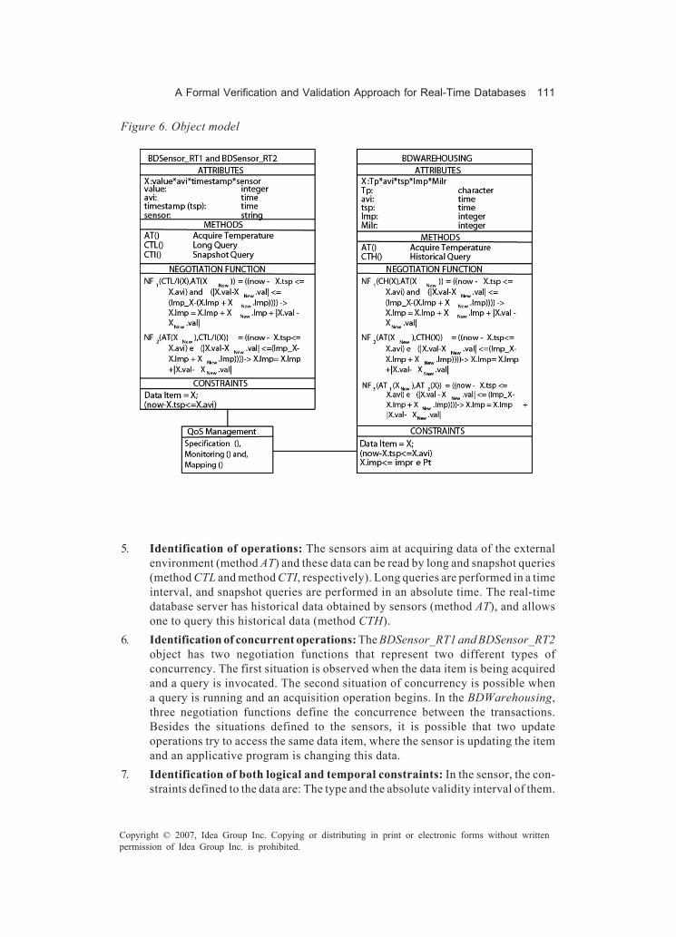
A Formal Verification and Validation Approach for Real-Time Databases 111
Copyright © 2007, Idea Group Inc. Copying or distributing in print or electronic forms without writtenpermission of Idea Group Inc. is prohibited.
5. Identification of operations: The sensors aim at acquiring data of the externalenvironment (method AT) and these data can be read by long and snapshot queries(method CTL and method CTI, respectively). Long queries are performed in a timeinterval, and snapshot queries are performed in an absolute time. The real-timedatabase server has historical data obtained by sensors (method AT), and allowsone to query this historical data (method CTH).
6. Identification of concurrent operations: The BDSensor_RT1 and BDSensor_RT2object has two negotiation functions that represent two different types ofconcurrency. The first situation is observed when the data item is being acquiredand a query is invocated. The second situation of concurrency is possible whena query is running and an acquisition operation begins. In the BDWarehousing,three negotiation functions define the concurrence between the transactions.Besides the situations defined to the sensors, it is possible that two updateoperations try to access the same data item, where the sensor is updating the itemand an applicative program is changing this data.
7. Identification of both logical and temporal constraints: In the sensor, the con-straints defined to the data are: The type and the absolute validity interval of them.
Figure 6. Object model

112 Neto, Perkusich, de Almeida, & Perkusich
Copyright © 2007, Idea Group Inc. Copying or distributing in print or electronic forms without writtenpermission of Idea Group Inc. is prohibited.
The constraints defined to the server are: the type of data item and the performancemetrics Pt and Impr, described in this chapter.
The QoS management is performed by the functions: specification, mapping, andmonitoring, in addition to the negotiation function defined for the objects. Figure 6illustrates the object model for the case study.
Building the Process ModelAccording to the steps defined to obtain the process model, we have:
1. Identification of the objects in HCPN: In this first step, the objects are identifiedfrom the object model for the the HCPN modules.
2. Identification of functions for each object: The sensor object implements themechanisms of acquisition and stored data, besides reading the content stored.The real-time database server object implements the update and reading of thedatabase.
3. Definition of interface for each object: In the HCPN module of sensor, the interfaceis defined by the methods: AT, CTL, and CTI and by attribute X that represents arecord. The interface of the HCPN module to the server object indicates themethods AT and CTH and the attribute DB that represent a record with the fieldsdefined to the data item stored in the server.
4. Definition of internal structure for each object: The internal structure is ahierarchical coloured Petri net to model the methods declared in the interface of theobject.
The overview of the process model is illustrated in Figure 7. The HCPN modules are:
• Declaration: This represents the declarations, that is, the functions, types, and soon.
• BDWarehousing: It is the database server.• Negotiation1 and Negotiation: This represents the negotiation functions.• Specification: It is the module where the temporal parameters are specified.• Sensor1, Sensor2, and Sensor3: This represents the modules for sensors.• UpdateS1, UpdateS2, and UpdateS3: These are the sensors’ transactions that
update the server.• MonitoringS1, MonitoringS2, and MonitoringS3: They are the monitoring func-
tions related to each sensor transaction.• Update and MonitoringUp: These modules are for the update transaction (only
read) and the monitoring function defined for it.• Active and Performance: These are control modules.
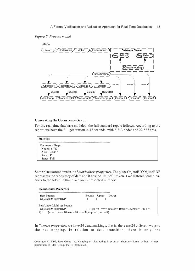
A Formal Verification and Validation Approach for Real-Time Databases 113
Copyright © 2007, Idea Group Inc. Copying or distributing in print or electronic forms without writtenpermission of Idea Group Inc. is prohibited.
Generating the Occurrence GraphFor the real-time database modeled, the full standard report follows. According to thereport, we have the full generation in 47 seconds, with 6,713 nodes and 22,867 arcs.
Statistics --------------------------------------------------------------------------- Occurrence Graph Nodes: 6,713 Arcs: 22,867 Secs: 47 Status: Full
Some places are shown in the boundedness properties. The place ObjetoBD’ObjetoBDPrepresents the repository of data and it has the limit of 1 token. Two different combina-tions to the token in this place are represented in report.
Boundedness Properties --------------------------------------------------------------------------- Best Integers Bounds Upper Lower ObjetoBD'ObjetoBDP 1 1 1 Best Upper Multi-set Bounds ObjetoBD'ObjetoBDP 1 1`{nr = t1,vrr = 10,avir = 10,tsr = 33,impr = 1,milr = 8}++ 1`{nr = t1,vrr = 10,avir = 10,tsr = 39,impr = 1,milr = 8}
In liveness properties, we have 24 dead markings, that is, there are 24 different ways tothe net stopping. In relation to dead transition, there is only one
Figure 7. Process model
Menu
Hierarchy Declaration Active Performance
Negotiation1 Negotiation2
BDWarehousing
Database Server
Specification
UpdateS1 UpdateS2 UpdateS3 Update
MonitoringS1 MonitoringS2 MonitoringS3 MonitoringUp
ReturnS1 ReturnS2 ReturnS3 ReturnTS1
Sensor1 Sensor2 Sensor3
sensor1 sensor2 sensor3

114 Neto, Perkusich, de Almeida, & Perkusich
Copyright © 2007, Idea Group Inc. Copying or distributing in print or electronic forms without writtenpermission of Idea Group Inc. is prohibited.
FCObjetoBDLeAt’AvaliaFCLeAt. This transition is dead, since neither conflict occurredwhen a read transaction was executing and a write transaction was invocated.
Liveness Properties --------------------------------------------------------------------------- Dead Markings: 24 [6713,6712,6711,6710,6703,...] Dead Transitions Instances: FCObjetoBDLeAt'AvaliaFCLeAt 1
Generating the Message Sequence ChartIn Figure 8, we have the MSC generated considering the scenario with two sensorsacquiring the same data item.
• Sensor1: writes periodically in the local database, the release time is 1 time unit(t.u.) and the period is 3 t.u.
• Sensor2: writes periodically in the local database, the release time is 9 t.u., and theperiod is 9 t.u.
Moreover, there are two write transactions and one read transaction.
Figure 8. Message sequence chart

A Formal Verification and Validation Approach for Real-Time Databases 115
Copyright © 2007, Idea Group Inc. Copying or distributing in print or electronic forms without writtenpermission of Idea Group Inc. is prohibited.
• Update 1: Periodically updates the database server object with respect to the datain Sensor1. The release time is 3 t.u., the computational time is 2 t.u., the deadlineis 12 t.u., and the period is 12 t.u.
• Update 2: Periodically updates the database server object for sensor2. The releasetime is 9 t.u., the computational time is 4 t.u., the deadline is 18 t.u., and the periodis 18 t.u.
• Query: Periodically queries the real-time database-server application. The releasetime is 3 t.u., the computational time is 6 t.u., the deadline is 12 t.u., and the periodis 12 t.u.
The release time is the moment when all the necessary resources to the execution of thetransaction and sensors are available. Starting from this moment the transaction will beready to be executed. The computation time is the processing time necessary to executeit. The deadline defines the maximum transaction execution period. Finally, the perioddefines the periodicity of the transaction and sensor.In the MSC, it is also possible to verify the QoS functions, where the negotiation betweentransactions conflicting and the time properties are visible during whole lifetime of asystem.
Generating the Timing DiagramIn Figure 9, the timing diagram for the execution of transactions and sensors is presented.In this figure, it is possible to see a representation of the timing model execution for bothtransactions and sensors, where the execution is represented by rectangles.In the vertical axis, the transactions and the sensors are represented. In the horizontalaxis the release time and the periods for both, transactions and sensors, and computa-tional times and deadline for transactions are represented. For each transaction, weconsider three states: start; processing, and committing. The start of the execution of
Figure 9. Timing diagram
Frequency and Time of Transactions Execution
Upd
ate/
Que
ry/S
enso
rs
Time (Time Unit)
0
1
2
3
4
5
6
7
3 6 9 12 15 18 21 24 27 30 33 36
Computation time=4,period=12,deadline=12Computation time=4,period=18,deadline=12Computation time=6,period=12,deadline=12
Sensor1, period=6Sensor2, period=9

116 Neto, Perkusich, de Almeida, & Perkusich
Copyright © 2007, Idea Group Inc. Copying or distributing in print or electronic forms without writtenpermission of Idea Group Inc. is prohibited.
a transaction is illustrated by a dotted line rectangle. The processing is represented bya filled rectangle, and the committing by a continuous line rectangle. For the sensor, weonly show the state processing.In the vertical axis, the Update 1 transaction is represented in 1. The Update 2 transactionis represented in 2. The Query transaction is represented in 3. The sensor1 is representedin 4, and the sensor2 in 5.
Future Trends
As for future trends, we believe that our method should be applied to other applicationdomains. Also, the method can be expanded in order to add more functionality andgraphs. Depending on the application domain, the method could be customized and itsphases adapted according to the domain features.Moreover, automatic code generation could be considered. It would be useful to ensurethat the programming code for the software is according to the verified and validatedmodel. In this context, we are currently developing an automatic code generator fromHCPN model to the Java programming language.
Conclusion
In this chapter we presented a method for real-time database verification and validation.The main objective of this method is to make possible the identification of wholecomponents of a system for modeling, analyzing, verifying, and validating them.The method is based on a model developed using hierarchical coloured Petri nets. Thecomputational tool used to generate the model, verifying the properties and generatinggraphs for validation by users was the design/CPN tool package.Using the proposed method, a real system can be studied without the danger, expense,or inconvenience of the manipulation of its elements. It is performed through the analysisof the system’s conceptual model and the application of guidelines which drive thedeveloper in the validation and verification activity.When dealing with complex systems, the process of analysis, verification, and validationneeds to be automated. However, the utilization of mathematical models is primordial,which allows automatic verification and validation. It makes it possible to identifyvarious potential deficiencies in the conceptual model, such as contradictions, ambigu-ity, redundancy, so forth.

A Formal Verification and Validation Approach for Real-Time Databases 117
Copyright © 2007, Idea Group Inc. Copying or distributing in print or electronic forms without writtenpermission of Idea Group Inc. is prohibited.
References
DiPippo, L. C. (1995). Semantic real-time object-based concurrency control. PhD thesis,Department of Computer Science and Statistics, University of Island, Kingston, RI.
Douglass, B. P. (2004). Real time UML: Advances in the UML for real-time systems (3rd
ed.). Boston: Addison-Wesley.Herrmann, J. (2001). Guideline for validation & verification real-time embedded
software systems. Software Development Process for Real-Time Embedded Soft-ware Systems (DESS), D 1.6.2, V 01.
Jensen, K. (1998). An introduction to the practical use of coloured Petri nets. In W. Reisig& G. Rozenberg (Eds.), Lectures on Petri nets II: Applications, Lecture Notes inComputer Science (vol. 1, pp. 237-292). Berlin, Heidelberg, Germany: Springer-Verlag.
Jensen, K. (1999). Design/CPN 4.0. Meta Software Corporation and Department ofComputer Science, University of Aarhus, Denmark. Retrieved May 19, 2006, fromhttp://www.daimi.aau.dk/designCPN/
Kang, K. D. (2001). qRTDB: QoS-sensitive real-time database. PhD thesis, Departmentof Computer Science, University of Virginia, Charlottesville.
Ribeiro-Neto, P. F., Perkusich, M. L. B., & Perkusich, A. (2003). Real-time databasemodeling considering quality of service. In Proceedings of the 5th InternationalConference on Enterprise Information Systems, Angers, France (vol. 3, pp. 403-410).
Ribeiro-Neto, P. F., Perkusich, M. L. B., & Perkusich, A. (2004). Scheduling real-timetransactions for sensor networks applications. In Proceedings of the 10th Interna-tional Conference on Real-Time Computing Systems and Applications (RTCSA),Gothenburg, Sweden (pp. 181-200). Berlin, Heidelberg, Germany: Springer-Verlag.
Rumbaugh, J., Blaha, M., Premerlani, W., Eddy, F., & Lorensen, W. (1991). Object-oriented modeling and design. Upper Saddle River, NJ: Prentice-Hall.
Selic, B., & Rumbaugh, J. (1998). Using UML for modeling complex real-time systems. InLCTES ’98: Proceedings of the ACM SIGPLAN Workshop on Languages, Compil-ers, and Tools for Embedded Systems (pp. 250-260). Berlin, Heidelberg, Germany:Springer-Verlag.

118 Toroi & Eerola
Copyright © 2007, Idea Group Inc. Copying or distributing in print or electronic forms without writtenpermission of Idea Group Inc. is prohibited.
Chapter VI
Requirementsfor the Testable
Specifications andTest Case Derivation inConformance Testing
Tanja Toroi, University of Kuopio, Finland
Anne Eerola, University of Kuopio, Finland
Abstract
Interoperability of software systems is a critical, everincreasing requirement insoftware industry. Conformance testing is needed to assure conformance of softwareand interfaces to standards and other specifications. In this chapter we shortly referto what has been done in conformance testing around the world and in Finland. Also,testability requirements for the specifications utilized in conformance testing areproposed and test-case derivation from different kinds of specifications is examined.Furthermore, we present a conformance-testing environment for the healthcare domain,developed in an OpenTE project, consisting of different service-specific and sharedtesting services. In our testing environment testing is performed against open interfaces,and test cases can, for example, be in XML (extensible markup language) or CDA R2(clinical document architecture, Release 2) form.

Testable Specifications and Test Case Derivation in Conformance Testing 119
Copyright © 2007, Idea Group Inc. Copying or distributing in print or electronic forms without writtenpermission of Idea Group Inc. is prohibited.
Introduction
In many organizations, the number of information systems is large and hence so areintegration needs between these systems. At the moment, new systems are integratedinto existing ones by tailoring them separately often by point-to-point integration. Thisis extremely expensive and inefficient in the long run. Application integration andprocess integration between organisations have increased the need to agree aboutcommon standards and open interfaces. By application integration we mean integrationbetween software systems, whereas by process integration we mean the integration ofhuman activities inside or between organisations. Normal software testing with differentvariations is important to assure functionality and quality of software systems, and theirinteroperability. If systems have open, standard-based interfaces their interoperabilityimproves, introduction and integration become easier and less local adaptation work isneeded. Today standardisation and conformance testing of open interfaces have beenemphasized nationwide and internationally. Normally, the target architecture is definedfirst and interface definitions are then derived based on it. However, the developmentis still in its infancy. Interface definitions are not enough, conformance testing is alsoneeded to examine if the systems really conform to standards or other specifications.Conformance testing can be utilised by component developers, component integratorsand software clients. Component developers can show conformity to the standards ofclients. Component integrator checks conformance to standards and integrates compo-nents without a great amount of local tailoring. Clients benefit from implementations thatconform to standards by getting better interoperability and quality of software. Inaddition, clients may only change some components when renewing the system, and abig-bang situation, in which the whole application must be renewed at the same time, canbe avoided.Standardisation and conformance testing have been studied quite a lot in the telecom-munication domain (ITU-T Recommendation X.290, 1996) but the practice is not well-established in other domains. Some business processes are quite deterministic (e.g.,order-delivery and referral-report), while others are nondeterministic (e.g., marketing andhome care) and the execution order of the processes can not be predicted as easily as theorder of manufacturing processes. In general, a great number of interfaces exist to othersystems. For example, in Kuopio University Hospital in Finland there are more than 180information systems, most of them with nonconsistent or nonexisting interfaces. Thoseinformation systems have to communicate inside and between different organisations.Local tailoring is needed, which, in turn, causes interoperability problems. Systems arehandling patient data. This also partly increases the difficulty to standardise data. Inaddition, systems are safety critical. Thus, interfaces and systems are harder to standardiseand conformance testing is more difficult to perform than in many other domains.Standards are needed to promote interoperability. However, it should be remembered thatstandards can also be contradictory, such as ISO 15745 and ISO 16100 standards forinteroperability (Kosanke, 2005).In the OpenTE project, our research problem is how to develop a reliable conformance-testing environment for healthcare applications. The environment should be applicablein the software industry and healthcare organisations. We use constructive and experi-

120 Toroi & Eerola
Copyright © 2007, Idea Group Inc. Copying or distributing in print or electronic forms without writtenpermission of Idea Group Inc. is prohibited.
mental research methods. At the moment, our prototype-testing environment consistsof different service-specific and shared testing services (see Figure 2). We have 13participants including research organisations, software companies, and healthcaredistricts in the OpenTE project. The OpenTE project continues the work done in thePlugIT project (from Oct 2001 to Aug 2004, see http://www.plugit.fi/english/), in whichopen interface specifications, such as common services, and context management, forhealthcare application were developed. We noticed that conformance testing of openinterfaces needs to be examined and elaborated upon. Thus, we developed a conform-ance-testing model to test applications’ conformity to specifications. The model consistsof four phases: an initial phase, testing performed by the developer, testing performedby the testing lab, and certificate issuing. Even though we have studied health informa-tion systems and their integration, similar integration needs can be found, and our modelis applicable to other domains and integration models. Our conformance-testing modelis discussed more in Toroi, Mykkänen, and Eerola (2005).The objective of this chapter is to propose new requirements for the interface specifica-tions from the testability point of view. The chapter strives to describe different kindsof specifications, evaluate how useable they are in the healthcare domain, and analysehow test cases can be derived from different specifications in conformance testing. Thechapter presents a conformance-testing environment developed in the OpenTE project.Furthermore, the chapter clarifies the conformance-testing position among other testingphases, compares interoperability testing to conformance testing, and considers respon-sibility questions of conformance testing.The rest of this chapter is organized as follows. First, we give background to conformancetesting in general and in healthcare domain. Second, we consider common requirementsfor the specifications and conformance testing, propose new requirements for theinterface specifications from the testability point of view, and analyse test-case deriva-tion from different specifications. Third, the OpenTE approach to conformance testingin the healthcare domain is discussed. We present a conformance-testing environmentdeveloped in our project, and analyse how test cases can be derived from differentspecifications in conformance testing. Finally, we discuss future trends and conclude thechapter.
Background
Conformance Testing in General
Software testing is an important tool for improving software quality and reliability.Software testing covers many kinds of testing methods, such as module, integration,acceptance, performance, and conformance testing. Each of the methods improvestesting, and strengthens each other’s. Attention should be given to the quality of testing,such as coverage, as well. Nowadays, open interface specifications and information-exchange standards have become general, which in turn enables the improvement oftesting.

Testable Specifications and Test Case Derivation in Conformance Testing 121
Copyright © 2007, Idea Group Inc. Copying or distributing in print or electronic forms without writtenpermission of Idea Group Inc. is prohibited.
Conformance is defined by ISO/IEC as the fulfilment of a product, process, or serviceof specified requirements (ISO/IEC Guide 2, 1996). A conformance clause is defined asa section of the specification that states all the requirements or criteria that must besatisfied to claim conformance. The term interoperability in software system point ofview means that a system is capable of executing services for other systems and utilizingservices from other systems (Herzum & Sims, 2000). Two common forms of testing forinteroperability are called interoperability testing and conformance testing.Interoperability testing is defined as the assessment of a product to determine if itbehaves as expected while interoperating with another product (Kindrick, Sauter, &Matthews, 1996). However, interoperability testing is not enough. It only tests that a setof systems are interoperating. It does not guarantee that other systems interoperate withthese systems. Conformance testing is needed to achieve a higher level of confidencethat these systems will successfully interoperate with other systems as well. Conform-ance testing is a way to verify implementations of the specification to determine whetheror not deviations from the specifications exist (Rosenthal & Skall, 2002). In conformancetesting, software implementations are black boxes; only the interfaces and their relation-ship to the specifications are examined. In other words, when an interface receives arequest, it is tested if the interface can handle the request and respond to it correctly.Conformance testing is necessary, but not sufficient, for interoperability, becauseconformance clauses (or specifications) typically only cover some aspects ofinteroperability. For example, infrastructure and techniques are implementation-specificfeatures not specified in the specification, thus influencing interoperability. Moseley,Randall, and Wiles (2004) assert that conformance testing is necessary in accomplishingeffective and rigorous interoperability testing. Thus, both interoperability and conform-ance testing are needed.There are many roles and activities involved in the conformance-testing process.Departments of government and legislation pass laws, decisions, recommendations, andreasons for specifications and conformance testing. It is good that oversight is thegovernment’s responsibility. However, government involvement in testing may alsohave dangerous features if government dictates what is being tested and how widely(Rada, 1996). Carnahan, Rosenthal, and Skall (1998) have introduced that interactionbetween roles, and activities can be illustrated by a diamond-shaped model, where eachrole (seller, certificate issuer, testing lab, and control board) is in the corner of thediamond. We have adapted the idea and compare the interaction to a triangle where thecertificate issuer and testing lab are not in separate roles (Toroi et al., 2005). A buyer(client) requires from a seller (developer) that a product conforms to the specification.The developer develops an application with certain interface implementations andapplies for the brand to the application. The testing lab/certificate issuer performsinterface testing and issues the brand if the application successfully completes theconformance testing. The control board is answering queries and disputes related to thetesting process. The developer is responsible for the product even if it had got the brandand passed the conformance testing.Regardless of all the above advantages it should be noticed that conformance testingcan not be used as verification. Conformance testing only increases the probability thatapplications are implemented according to the interface specification. The developer andthe integrator must perform normal software inspections and testing phases before

122 Toroi & Eerola
Copyright © 2007, Idea Group Inc. Copying or distributing in print or electronic forms without writtenpermission of Idea Group Inc. is prohibited.
conformance testing. The conformance-testing phase depends on the level of thespecification against which testing is performed. If the specification is at a detailed level,conformance testing is performed quite early in the implementation process. If thespecification covers the whole system conformance testing is performed after the wholedevelopment phase.
Conformance Testing in Healthcare
Software companies and healthcare organizations strive to improve health informationsystems. Today, one of the most important goals is a seamless and flexible service chainfor patients. This requires that doctors and nurses exchange information and useapplications in an efficient, safe, and secure way. Personnel in a hospital do not work allthe time with computers. Most of the communication is asynchronous and there is alsoa lot of manual work. In this situation users need an agreed mode of action and somesoftware facilitating communication.Integrating the healthcare enterprise (IHE) promotes the use of standards by developingintegration profiles (HIMSS & RSNA, 2002). With the help of integration profiles,standards can be implemented to the implementations at a more accurate level.Australian Healthcare Messaging Laboratory (AHML) is a part of the CollaborativeCentre for eHealth (CCeH) at the University of Ballarat. AHML provides message testing,compliance and certification services for developers and vendors, system integratorsand users within the healthcare industry. Clients can send electronic healthcare mes-sages via the Internet to the AHML Message Testing Engine. Messages are testedagainst healthcare messaging standards. Test cases are built using messaging standardsand client-specific requirements, if any. Message-based integration may lead to data-oriented integration, where data has been copied into several places. Thus we haveinvestigated other possibilities — for example, API, service, and component basedintegration. Because people’s work, in co-operation and communication, is often asyn-chronous, process integration and application integration are needed at the same time.The Software Diagnostics and Conformance Testing Division (SDCT), part of NIST’s(National Institute of Standards and Technology) Information Technology Laboratoryis working with industry by providing guidance on conformance topics, helping todevelop testable specifications, and developing conformance tests, methods and toolsthat improve software quality and conformance to standards. SDCT has especiallyfocused on developing XML conformance test suites and has also written guidance onhow to write better specifications. NIST, the World Wide Web Consortium (W3C) andthe Organization for the Advancement of Structured Information Standards (OASIS)have given guidance on how specifications should be written. OASIS has published adocument describing how to specify software conformance to a specification, andidentifying conformance requirements to be included in specifications (Rosenthal &Skall, 2002). W3C has put effort on quality assurance and specification guidelines (W3C,2005).Health Level 7 (HL7) Conformance SIG (Special Interest Group) attempts to improveinteroperability and certification processes. HL7 provides a mechanism to specify

Testable Specifications and Test Case Derivation in Conformance Testing 123
Copyright © 2007, Idea Group Inc. Copying or distributing in print or electronic forms without writtenpermission of Idea Group Inc. is prohibited.
conformance for HL7 Version 2.X and HL7 Version 3 messages and provide a frameworkfor facilitating interoperability using the HL7 standard. The problem with HL7 version2.X standards is that they are difficult to use in practice, and users are unable to ascertaincompliance with standards against their specific needs (TNT Global Systems, 2002). Asa solution, HL7 has developed message profiles, which add specificity to existingmessages and identify scenarios by providing a template for documenting particular usesof HL7 messages. In our research, the minimum-level specification was specified forCCOW, HL7 standard (Tuomainen, Mykkänen, Rannanheimo, Komulainen, & Korpela,2004). CCOW was adapted to the minimum-level specification, and only the mostessential parts of it have been included.In our testing environment, testing is performed against open interfaces, and test casescan be, for example, in XML or CDA R2 forms. Furthermore, new requirements forspecifications from the testability point of view have been proposed.
Requirements for theTestable Specifications
In this section, common requirements for the specifications are considered, new require-ments for the interface specifications from the testability point of view are proposed, andtest-case derivations from different specifications are analysed.
General Requirements for the Specifications
A specification can be in different states: draft, accepted, or publicly available specifi-cations. At first, specifications are drafts. However, draft specifications are not testable.When a management group accepts a draft specification, it becomes an accepted versionof the specification. If an accepted specification is published, it becomes a publiclyavailable specification. If a specification is accepted or public, it is sufficiently testableand hopefully stable. Software compared to the specifications has three states, available,implemented, or conformable to specification. Available state means that the softwareexists but it does not necessarily have any implemented interfaces according to thespecifications. An implemented state means that the specified interfaces have beenimplemented to software. When the developer has implemented interface implementa-tions to the software, testing has to be performed to verify conformance to thespecification. A testing lab performs conformance testing. If the software passes thetests, it moves to a conformable-to-specification state and the brand can be issued tothe software. Specifications in the healthcare context are further discussed in the section“General Requirements in Healthcare Domain”.

124 Toroi & Eerola
Copyright © 2007, Idea Group Inc. Copying or distributing in print or electronic forms without writtenpermission of Idea Group Inc. is prohibited.
Testability of the Specifications
Binder (1994) has presented testability factors in object-oriented systems. Key testabil-ity factors are representation, implementation, built-in test, test suite, test tools, and testprocess. When considering testability of the interface specifications, representation,test suite, and test process can be used. Next, we adapt Binder’s view and describe thosein more detail.
Representation
The form of the specifications can range from formal specifications to natural-languagestatements. The more formal the specification is, the more testable it is. Governmentallaws, decisions, and recommendations — as well as specifications — are mostly writtenin natural language. Actors in different organisations need to use specifications ininvitation for tenders when ordering applications and they have to understand specifi-cations. Natural language is used because it is easier to form and understand than formallanguages. The specification has to be current, so that conformance testing is performedagainst the right version, and test cases test the right features. Models and diagrams helpto understand the specification better, so they improve testability. Use case and scenariodiagrams are especially useful. Permitted combinations of the parameters have to berestricted because, for example, if it is allowed to search anything with any key, thenumber of combinations explodes. However, it is the fact that everything cannot betested anyway. Specification must be explicit, unambiguous, and consistent. Further-more, it must contain only measurable, feasible, realistic, and necessary requirements.
Test Suite
It is advantageous to deliver a test suite with the specification. For example, NIST isdelivering a test suite for ebXML messaging. This assists testing because certain issuescan be discovered beforehand and more testing time can be devoted to one’s own,situation-specific test cases. It is easier to follow specifications if test cases are ready-made. However, the official conformance test suite can also have errors (Garstecki, 2003).
Test Process
Reviews and inspections of the specification and prototyping are normal quality-assurance practices. Reference implementations can be made to help developing speci-fications and test cases (Mykkänen et al., 2004). In an ideal situation specifications, testcases, and reference implementations are developed simultaneously. This guaranteesthat when the final version of the specification is ready, it is more mature, and there isno need to change it immediately afterward. Further, we propose that conformance

Testable Specifications and Test Case Derivation in Conformance Testing 125
Copyright © 2007, Idea Group Inc. Copying or distributing in print or electronic forms without writtenpermission of Idea Group Inc. is prohibited.
testing should allow those deviations from specifications which are not significant andwhich do not harm the purpose and semantics — for example, resilience of tagged datain XML (solved with dispatchers).
New Proposed Requirements for the Specifications
The specifications have to be defined so that testability and conformance are taken intoconsideration early in the specification lifecycle. In that case requirements in thespecification will be testable and definite. Otherwise, it could happen that implementa-tions are even impossible to test against specifications. W3C and OASIS have givenguidance on how specifications should be written (Rosenthal & Skall, 2002; W3C, 2005).According to the guidelines, a specification must contain a conformance clause and usekey words to specify conformance requirements. In the conformance clause all therequirements or criteria that must be satisfied to claim conformance are defined (ISO/IECGuide 2, 1996). The conformance clause shall address the following issues: what needsto be conformed, modularity, profile and levels, extensions, discretionary items, depre-cated features, languages, and characters coding. We have adapted and extended theOASIS and W3C guidelines for the conformance specifications. We propose thefollowing additional aspects that the specification must address:
• Architecture: A target architecture description is utilized to show principledecisions and visions in the domain. The architecture description will help usersof the conformance clause to understand why given specifications are needed.Thus, it assists in conforming. Specifications should be modular. If needed, theyare divided into subspecifications. Further, the specification must be possible tobe composed to other specifications not known beforehand. Relationships anddependencies between specifications should be clearly defined and minimized(cohesion, coupling).
• Specification levels: Domain-related specifications should be distinguished fromtechnical specifications. Thus, it is good to divide the specification into levels, forexample, functional-, conceptual-, and technical-level specifications, where eachof the levels contains only certain issues. Different actors can view differentdocuments and do not have to look for features they are interested in among all theother features. Functional level specifications include all the user actions withexecution order and exceptions. The specification has to define execution order ofthe deterministic actions with scenario diagrams. Conceptual-level specificationcontains all the used concepts and relationships to the other specifications.Software clients can use functional and conceptual level specifications whenadding specifications to the call for tenders, and requiring standard-based soft-ware. Technical-level specification contains all the technical details needed toimplement specifications, such as interfaces, methods, parameters, infrastructuredescriptions, and usage examples. Furthermore, the specification has to specifypre- and post-conditions for all the methods. Pre- and post-conditions improvetestability.

126 Toroi & Eerola
Copyright © 2007, Idea Group Inc. Copying or distributing in print or electronic forms without writtenpermission of Idea Group Inc. is prohibited.
• Interoperability: Everything concerning software interoperability has to be men-tioned in the specification. The specification has to define how implementationshave to handle distribution, data security, encryption, and transactions. Also, thequality requirements are indicated in the specification if they are essential for thesituation. Useful quality requirements are, for example, continuous operating time(7 days a week/24 hours a day), execution time, robustness, usability, memoryrequirements, and response time. Requirements depending on the situation areincluded in the specification only if needed.
• Extensions in the future: In order to be prepared for the future, a specification hasto list all the possible extensions and new features that the implementations have.For example, the specification should be simple enough at first and featuresdiscovered advantageous in practice are added to it later on. However, thespecification has to be reasonable, so that implementations conforming to it havean acceptable cost level. Extensions can harm the interoperability and causetroubles in the future. When the extended implementation is delivered to severalclients and the specification later undergoes changes that influence the extendedpart conflictingly, the implementation may be costly or even impossible to updateconsistently with the specification. Further, if deprecated features are documentedthey can stay better in mind, and can be mixed with supported features. Thus, onemust consider carefully whether a description of deprecation is more trouble thanit is worth.
• Re-evaluation: In the specification, we must describe how different versions ofimplementations, specifications, and test suites affect conformance, that is, in whatsituations conformance remains and when conformance has to be re-evaluated.Normally, if a new version of the specification is released, the old conformanceholds, but retesting is needed against the new version of the specification. If a newversion of the implementation is released conformance always has to be retestedfor the new version of the implementation. Implementations tested with differenttest-suite versions can conform to the specification but are not necessarilyinteroperable, for example, because of the extended features.
• Key words: Key words are used to specify requirements in the specification.Requirements can be mandatory, conditional, optional, or suggested (Rosenthal& Skall, 2002). We have noticed in workshops with software and healthcareorganisations that conditional,that is, the key word SHOULD, must be avoidedbecause it is confusing and causes interoperability problems. It is recommendedthat requirements are either obligatory (conformance testing is needed) or com-pletely optional (conformance testing is not needed). Requirements have to beprioritized and conflicts solved in the requirement-specification phase, not left tothe implementers. However, when eliciting requirements, the key word SHOULD isuseful in getting comments and ideas from the developers to those who definespecifications.
Testable Specifications and Test Case Derivation in Conformance Testing 127
Copyright © 2007, Idea Group Inc. Copying or distributing in print or electronic forms without writtenpermission of Idea Group Inc. is prohibited.
Test-Case Derivation from the Specifications
The ease of test case derivation from the specifications influences testability of thespecifications. Specifications can be grouped from the most formal to the least formalspecifications: formal, semiformal, and natural-language specifications. In the following,specifications and test-case generation from them are presented in more detail.
• Formal languages: If the specification is given in formal language, for example, Z-language (Barden, Stepney, & Cooper, 1994), the specification is exact, and testcases can be derived automatically from it. For the use of formal languages thereare tools, for example, PROBE, and ClawZ. However, formal languages are quitecomplex to formulate, even for experts. In order to utilise specifications softwareclients have to understand them properly but formal languages are difficult tointerpret. They are suitable for situations where exact mathematics is needed andsufficient expertise is available, such as in radiotherapy.Logical expressions can be also thought of as formal languages. If the specificationis already in axiomatic form, test cases are derived from logical expressions. If thespecification has been written in natural language it is translated into logicalexpressions at first, and then test cases are derived from them (Rosenthal, Skall,Brady, Kass, & Montanez-Rivere, 1997). The method can be used when thespecification is already in axiomatic form, for example, when deciding detrimentalside effects of medication. However, if the specification has to be translated intological expressions, at first, we think that translation is quite troublesome, and toomany interpretations and ambiguity remain. In addition, conformance to thespecification cannot be proved. It can only be proved that the implementation isnot conformable to the specification.The test suite can also be defined in formal language. One method is to describetest suite in formal Tree and tabular combined notation (TTCN), which is based onISO 9646-3 (X.292) standard. Test cases are derived automatically from the abstracttest suite, for example, with the help of Open TTCN, Telelogic TAU TTCN Suite,or Clarinet-TTCN ATM ETS tools. TTCN language is in extensive use in telecom-munication applications but it may not be equally applicable to other domains. Tobe used efficiently, for example, in healthcare domain the notation should bemodified. However, the editing is quite inconvenient. Furthermore, the order of theoperations is not always as predetermined as in the telecommunication domain.
• Semiformal languages: Useful semiformal languages are, for example, UML statediagrams, use cases, and scenario diagrams. They are well-known methods, andquite easy to use and understand. If the specification is defined with UML state-diagram, test cases can be derived from it (Gnesi, Latella, & Massink, 2004). Gnesi,Latella, and Massink have developed a theoretical background to generate testcases automatically in a conformance testing setting. However, proper test- andregression-test-selection techniques are still needed to use this method in practice.This method is suited for situations in which actions have clear execution order,and are deterministic, that is, a certain input causes transition to a certain state.However, it is not very useful in nondeterministic situations, in which the order of

128 Toroi & Eerola
Copyright © 2007, Idea Group Inc. Copying or distributing in print or electronic forms without writtenpermission of Idea Group Inc. is prohibited.
the activities is not known beforehand, such as communication in organisationalnetworks and expert organisations.El-Fakih, Yevtushenko, and Bochmann (2004) have presented the conformancespecification in the form of a finite state machine (FSM). Implementation is alsopresented in the form of FSM. Test cases are derived from it. By comparing FSMsit can be observed if the implementation is conformable to the specification. El-Fakih et al. assume that the parts of the implementation that correspond to theunmodified parts of the specification have not been changed. However, in regres-sion testing the parts in which the change might have been influenced also haveto be retested. There is a chance that the kind of FSM cannot be formed from theimplementation, which defines exactly the implementation and not what shouldhave been done. This method is useful in the situations where interoperabilitybetween components or systems is tested, as long as interoperability is definedwith FSM. However, usually, interaction between information systems is not fixedin the specifications. If COTS components are tested, the source code is notavailable, so the method cannot be used.If the specification is in the form of use cases, test cases are derived from them.However, there exists a gap between an implementation and a specification. Testcases cannot be derived automatically from use cases; however, there is a biginterest to that direction. For example, Binder (1999) has presented extended usecases. The problem with extended use cases is that use cases are not used to specifyperformance or fault tolerance. Kirner et al. (1999) have proposed that the use casescan be extended into behaviour cases, which are implementation-specific descrip-tions of a specific use case. Then, the behaviour cases can be extended into testcases. Alexander (2003) has proposed misuse cases as a tool for finding securityrequirements and decreasing risks.The semiformal specification can also be XML-based. XML-format helps tounderstand specification in technical level and clarifies it. Bhatti, Bertino, Ghafoor,and Joshi (2004) have proposed XML-based specification language for securitymodels. It incorporates content- and context-based dynamic-security require-ments for documents in XML-based Web services.
• Natural language: If the specification has been generated in natural language, testcases can be derived by hand and, for example, by using reference implementations.Natural-language specification can be used when official certified implementationsare not the main goal. They are more suitable for informal conformance reviews.More formal specifications are needed to avoid inconsistencies and inaccuracies.If semiformal specifications are not available in testing, testers can form neededdiagrams and confirm their validity from the developer and client organisations.
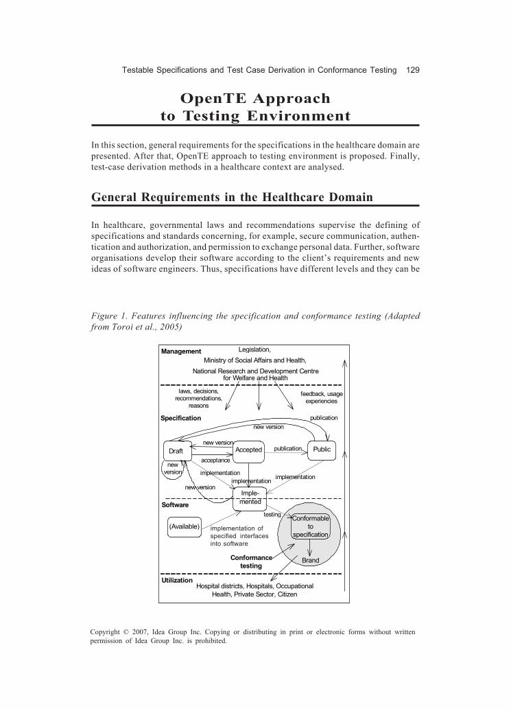
Testable Specifications and Test Case Derivation in Conformance Testing 129
Copyright © 2007, Idea Group Inc. Copying or distributing in print or electronic forms without writtenpermission of Idea Group Inc. is prohibited.
OpenTE Approachto Testing Environment
In this section, general requirements for the specifications in the healthcare domain arepresented. After that, OpenTE approach to testing environment is proposed. Finally,test-case derivation methods in a healthcare context are analysed.
General Requirements in the Healthcare Domain
In healthcare, governmental laws and recommendations supervise the defining ofspecifications and standards concerning, for example, secure communication, authen-tication and authorization, and permission to exchange personal data. Further, softwareorganisations develop their software according to the client’s requirements and newideas of software engineers. Thus, specifications have different levels and they can be
Figure 1. Features influencing the specification and conformance testing (Adaptedfrom Toroi et al., 2005)
AcceptedDraft Public
Conformancetesting
testing
implementationo f s p e c i f i e di nt er f ac es in t osoftware
Legislation,Ministry of Social Affairs and Health,
National Research and Development Centrefor Welfare and Health
laws, decisions,recommendations,
reasons
feedback, usageexperiencies
Hospital districts, Hospitals, OccupationalHealth, Private Sector, Citizen
acceptance
Imple-mented
implementation implementation
new versionpublication
new versionimplementation
publicationnew version
(Available)
newversion
Specification
Software
Management
Utilization
Brand
Conformableto
specificationimplementation ofspecified interfacesinto software
130 Toroi & Eerola
Copyright © 2007, Idea Group Inc. Copying or distributing in print or electronic forms without writtenpermission of Idea Group Inc. is prohibited.
more or less official. The more official the specification is the more critical it is and themore testing that is needed.In Finland, laws, decisions, recommendations, and reasons for specifications andconformance testing are given by legislation, the Ministry of Social Affairs and Health,and the National Research and Development Centre for Welfare and Health (see Figure1). Specifications have three different states: drafts, accepted, or publicly availablespecifications. At first, specifications are drafts. When management group accepts adraft specification, it becomes an accepted version of the specification. If an acceptedspecification is published, it becomes a publicly available specification. Software hasthree states, available, implemented or conformable to specification. Available statemeans that there exists the software but it does not necessarily have any implementedinterfaces according to the specifications. Implemented state means that the specifiedinterfaces have been implemented to software. When the developer has implementedinterface implementations to the software, testing has to be performed to verify conform-ance to the specification. A testing lab performs conformance testing and if the softwarepasses the tests the software becomes conformable to specification state and the brandcan be issued to the software.Hospital districts, hospitals, occupational health, private sector, and citizens utilizesoftware conformable to specifications. They also give feedback and usage experiencesto software organisations, specifications constructors (e.g., special interest groups andHL7), and management.
Conformance-Testing Environment
In the OpenTE project we are developing a conformance-testing environment for severalweb-based testing services, for example, CDA R2, lightweight context management, andcommon service interfaces. We have studied conformance-testing actions in presentstate in healthcare software companies, and got good ideas for the development of theconformance-testing environment. We have made requirement specification and tech-nical specification of the environment, and functional specifications are now beingconstructed. Healthcare and software organisations have commented on our specifica-tions, and we have gotten positive feedback. Furthermore, we have made a prototype ofthe testing environment, and it has been presented in workshops.The idea of the common testing environment is quite new and progressive, thuscomments and ideas have been quite conservative, and we have had difficulties in findingmutual understanding in distribution of work and responsibility questions. The respon-sibility questions and detailed development of the testing environment will become clearin near future.Testing environment consists of different service-specific and shared testing services(see Figure 2). At the moment, service-specific testing services cover regional informa-tion systems, common services, and lightweight context management. Services can beextended in the future. Shared testing service handles, for example, user authentication,code sets, reports, invoicing, and test log. In the environment, test cases can be derivedfrom different kinds of specifications. Furthermore, test cases can be in different formats,

Testable Specifications and Test Case Derivation in Conformance Testing 131
Copyright © 2007, Idea Group Inc. Copying or distributing in print or electronic forms without writtenpermission of Idea Group Inc. is prohibited.
for example, CDA R2, XML, and http. Testing service acts as a needed counterpart inconformance testing. For example, if an implementation of a regional information systemattends the testing service, the testing service acts as a surrogate of the health-information system. If a lightweight context-management client attends the service, thetesting service acts as a lightweight context-management server. Furthermore, test datacan be downloaded through the service — for example, test electronic patient records.During the project the focus has been changed from CDA R1 to CDA R2, and requirementsfor test-case derivation have been increased. Thus, we examined different specificationsand considered how test cases can be derived from them. Next we give a summary of thetest case derivation methods in a healthcare context.
Figure 2. OpenTE testing environment for conformance testing
lightweight Context ManagementTest Service
PlugIT/HL7 Common ServicesTest Service
nationallyagreed testdata (e.g.,test EPR)
Impl. ofRegional
InformationSystem
Impl. ofHealth
InformationSystem
lightweightContext
Managementclient
lightweightContext
Managementserver
CommonServices -
client
CommonServices -
server
CDA
XML
http(s)
Regional Information SystemTest Service
HealthInformation
SystemSurrogate
RegionalInformation
SystemSurrogate
server
client
server
client
Other Test ServicesDownloadable Test Data
Test Report,Test Log
nationallyagreed testdata (e.g.,test EPR)
Download
TESTING SERVICE
Shared TestingServices

132 Toroi & Eerola
Copyright © 2007, Idea Group Inc. Copying or distributing in print or electronic forms without writtenpermission of Idea Group Inc. is prohibited.
Summary of the Test-Case Derivation Methods inHealthcare Context
Test cases can be derived from formal, semiformal, and natural-language specificationsin many different ways. In this section, we study test-case derivation from different kindsof specifications in a healthcare context. The most formal methods are discussed first.Test cases can be derived automatically from formal languages. However, formallanguages are considered to be too complex to use in practice, and they are not verysuitable for the healthcare domain. In order to exploit specifications, healthcare clientshave to understand them properly but formal languages are difficult to interpret. We thinkthat semiformal languages are more suitable for the healthcare domain, because theirnotation is more understandable, and easier to use and interpret than formal languages.One disadvantage of semiformal languages is that test cases cannot be derived automati-cally from the specifications.We studied how test cases can be derived from an activity diagram, use-case diagram,and state diagram (Jäntti & Toroi, 2004). Activity diagrams show different action flowsthat a tester must go through in testing. Action flows help testers to develop extensivetest cases, although the abstraction level may be too high for testing purposes. UML usecases provide a way to divide the system under test into smaller functional units, andtest cases can be organized by use cases. Use-case scenarios include descriptions ofexceptional and alternative flows that are often sources of defects. We have noticed thatthe state diagram is an applicable tool for describing domain-specific concepts (e.g.,patient, referral) with relevant states and state transformations, which need to be definedin specifications. Test cases are easy to identify from the UML state diagram and the statetransition table. We have also defined test cases based on inputs of different granularities,that is, action flow of users, operation flow of interfaces, and method flow inside software(Toroi, Jäntti, Mykkänen, & Eerola, 2004). Our method is applicable if user actions aredescribed with action diagrams and software is described with use-case and scenariodiagrams.XML-based specifications can be viewed as semiformal specifications. We definedXML-based specifications for common services in the PlugIT project (Mykkänen et al.,2004). Test cases were defined from the specification by hand using reference implemen-tations. Yet, we think that the test cases could have been derived semi-automatically, too.In addition, we have used XML in the OpenTE project when test data was transformedfrom a legacy system to CDA R2 format, which is needed, for example, to test the electronicpatient record. The transformation was quite troublesome.Governmental laws, recommendations, and specifications created in special interestgroups have been written in natural language. In the PlugIT project, we used HL7 Finlandspecifications, which are national recommendations, and reference implementations intest case generation. Natural language specifications were easy to read and understandbut they contained inconsistencies and inaccuracies, further, test case generation byhand was a big disadvantage. It would have been nice to get test cases automatically fromthe specifications but it was not possible. Furthermore, diversity and adequacy of testcases were not very good. Efficient conformance testing requires that specifications be
Testable Specifications and Test Case Derivation in Conformance Testing 133
Copyright © 2007, Idea Group Inc. Copying or distributing in print or electronic forms without writtenpermission of Idea Group Inc. is prohibited.
transformed in semiformal language. The problem here is that it is difficult to findconsensus between different organisations. The following questions arise: Who isresponsible for transformation? Who is skilful and competent enough to accomplishtransformation? Who shall pay the costs? Which organization gets rights to work asconformance tester authorized to issue brands? However, collaboration is necessary todecrease costs and increase quality, efficiency, interoperability, and reliability ofsoftware.
Future Trends
We have to study further test-case derivation from the specifications and from the testdata. The more automatically derivation is performed, the better. Furthermore, test-caseselection in the regression-testing phase is an interesting question. We have to studywhich test cases have to be retested if implementation has undergone changes, so thatnot all the test cases have to be selected but conformance can be assured. Differentspecifications can be used in different situations. We have to study further, whichspecification style is the best in certain situations and how feasible and efficient methodsare in practice in the healthcare domain.
Conclusion
In this chapter, we presented new requirements for the interface specifications from thetestability point of view. We found that the form of the specification and exactness wereimportant features. In addition, we noticed that domain-related specifications should bedistinguished from technical specifications. Thus, it is good to divide the specificationinto levels — for example, functional, conceptual, and technical level specifications —where each of the levels contains only certain issues. We described different kinds ofspecifications, evaluated how useable they are in the healthcare domain, and comparedtheir automatic test-case generation. Formal specifications are exact and test cases canbe derived automatically from them. However, they are often too complex to use inpractice, and in particular they are not very suitable for the healthcare domain. Naturallanguage specifications are easy to form and understand but they are too ambiguous.Thus, they are more suitable for informal conformance reviews than for conformancetesting. We propose that semiformal languages are the most suitable for the healthcaredomain, because their notation is more understandable. They are easier to use andinterpret than formal languages, and they are more precise than natural languages.Furthermore, we presented a conformance-testing environment developed in the OpenTEproject, in which test cases can be derived from different kinds of specifications. Testingservice in a testing environment acts as a needed counterpart in conformance testing.
134 Toroi & Eerola
Copyright © 2007, Idea Group Inc. Copying or distributing in print or electronic forms without writtenpermission of Idea Group Inc. is prohibited.
Acknowledgments
This chapter is based on research in the OpenTE project, funded by the NationalTechnology Agency TEKES, software companies, and hospital districts in Finland. Theauthors thank all the involved participants in this project.
References
Alexander, I. (2003). Misuse cases: Use cases with hostile intent. IEEE Software, 20(1),58-66.
Barden, R., Stepney, S., & Cooper, D. (1994). Z in practice. Prentice-Hall.Bhatti, R., Bertino, E., Ghafoor, A., & Joshi, J. (2004). XML-based specification for Web
services document security. IEEE Computer Society, 37(4), 41-49.Binder, R. (1994). Design for testability in object-oriented systems. Communication of
the ACM, 37(9), 87-101.Binder, R. (1999). Testing object-oriented systems: models, patterns and tools. Addison
Wesley.Carnahan, L., Rosenthal, L., & Skall, M. (1998). Conformance testing and certification
model for software specification. In Proceedings of the ISACC ’98 Conference.El-Fakih, K., Yevtushenko, N., & Bochmann, G. (2004). FMS-based incremental conform-
ance testing methods. IEEE Transactions on Software Engineering, 30(7), 425-436.
Garstecki, L. (2003). Generation of conformance test suites for parallel and distributedlanguages and APIs. In Proceedings of the Eleventh Euromicro Conference onParallel, Distributed and Network-based Processing, Italy (pp. 308-315).
Gnesi, S., Latella, D., & Massink, M. (2004). Formal test-case generation for UMLstatecharts. In Proceedings of the IEEE International Conference on EngineeringComplex Computer Systems Navigating Complexity in the e-Engineering Age,Italy (pp. 75-84).
Herzum, P., & Sims, O. (2000). Business component factory. Wiley Computer Publishing.HIMSS, & RSNA (2002). Integrating the healthcare enterprise — IHE technical
framework volume I — integration profiles, Revision 5.3. HIMSS/RSNA.ISO/IEC Guide 2. (1996). 1996 Standardization and Related Activities: General Vocabu-
lary.ITU-T Recommendation X.290. (1996). OSI conformance testing methodology and
framework for protocol recommendations for ITU-T applications — generalconcepts.
Jäntti, M., & Toroi, T. (2004). UML-based testing — A case study. Proceedings of 2nd
Nordic Workshop on the Unified Modeling Language, Finland (pp. 33-44).

Testable Specifications and Test Case Derivation in Conformance Testing 135
Copyright © 2007, Idea Group Inc. Copying or distributing in print or electronic forms without writtenpermission of Idea Group Inc. is prohibited.
Kindrick, J., Sauter, J., & Matthews, R. (1996). Improving conformance and interoperabilitytesting. StandardView, 4(1), 1996.
Kirner, D., Porter, R., Punniamoorthy, P., Schuh, M., Shoup, D., Tindall, S., et al. (1999).Extending use cases throughout the software lifecycle. Software EngineeringNotes, 24(3), 66-68.
Kosanke, K. (2005). ISO standards for interoperability: A comparison. In Pre-Proceed-ings of the First International Conference on Interoperability of EnterpriseSoftware and Applications, Switzerland (pp. 59-67).
Moseley, S., Randall S., & Wiles, A. (2004). In pursuit of interoperability. InternationalJournal of IT Standards and Standardization Research, 2(2), 34-48.
Mykkänen, J., Porrasmaa, J., Korpela, M., Häkkinen, H., Toivanen, M., Tuomainen, M.,et al. (2004). Integration models in health information systems: Experiences from thePlugIT project. In Proceedings of the 11th World Congress on Medical Informatics.San Francisco (pp. 1219-1222).
Rada, R. (1996). Who will test conformance? Communications of the ACM, 39(1), 19-22.Rosenthal, L., & Skall, M. (Eds.). (2002). Conformance Requirements for Specifications
v1.0. Retrieved December 10, 2004, from http://www.oasis-open.org/committees/download.php/305/conformance_requirements-v1.pdf
Rosenthal, L., Skall, M., Brady, M., Kass, M., & Montanez-Rivera, C. (1997). Web-basedconformance testing for VRML. StandardView, 5(3), 110-114.
TNT Global Systems (2002). National electronic healthcare claims standard, conform-ance and compliance issues (white paper). Author.
Toroi, T., Jäntti, M., Mykkänen, J., & Eerola, A. (2004). Testing component-basedsystems—The integrator viewpoint. In Proceedings of the 27th Information Sys-tems Research Seminar, Scandinavia, Sweden.
Toroi, T., Mykkänen, J., & Eerola, A. (2005). Conformance testing of open interfaces inhealthcare applications—Case context management. In Pre-Proceedings of theFirst International Conference on Interoperability of Enterprise Software andApplications, Switzerland (pp. 535-546).
Tuomainen, M., Mykkänen, J., Rannanheimo, J., Komulainen, A., & Korpela, M. (2004).User-driven clinical context management with low implementation threshold (ab-stract). In M. Fieschi, E. Coiera, & Y. C. Li, (Eds.), MEDINFO 2004: Building highperformance health care organizations, San Francisco.
W3C (2005, April 28). QA framework: Specification guidelines (working draft). RetrievedMay 12, 2005, from http://www.w3.org/TR/qaframe-spec/

136 Polo & Piattini
Copyright © 2007, Idea Group Inc. Copying or distributing in print or electronic forms without writtenpermission of Idea Group Inc. is prohibited.
Chapter VII
Test-CaseMutation
Macario Polo, University of Castilla - La Mancha, Spain
Mario Piattini, University of Castilla - La Mancha, Spain
Abstract
This chapter presents a new testing technique called “test-case mutation.” The ideais to apply a set of specific mutation operators to test cases for object-oriented software,which produces different versions of the original test cases. Then, the results of theoriginal test case and of its corresponding mutants are compared; if they are verysimilar, the technique highlights the possible presence of a fault in the class under test.The technique seems useful for testing the correctness of strongly constrained classes.The authors have implemented a supporting tool that is also described in the chapter.
Introduction
Source-code mutation is a testing technique whose main goal is to check the quality oftest cases used to test programs. Basically, a program mutant is a copy of the programunder test, but with a small change in its source code, such as the substitution of “+”by “-.”Thus, this small change simulates a fault in the program, the program mutanttherefore being a faulty version of the program under test. If a test case is executed both

Test-Case Mutation 137
Copyright © 2007, Idea Group Inc. Copying or distributing in print or electronic forms without writtenpermission of Idea Group Inc. is prohibited.
on the program being tested and on a mutant and their outputs are different, then it issaid that the mutant is “killed.” This means that the test case has found the faultintroduced in the original program and, therefore, the test case is “good.”Changes in the source code are seeded by mutation operators that, in many cases, arelanguage-dependent (i.e., there are mutation operators specifically designed for Java,C++, etc.).Although powerful, source-code mutation is computationally a very expensive testingtechnique (Baudry, Fleurey, Jézéquel, & Traon, in press; Choi, Mathur, & Pattison, 1989;Duncan, 1993; Mresa & Bottaci, 1999; Weiss & Fleyshgakker, 1993). In fact, source-codemutation has several very costly steps:
• Mutant generation: Offut, Rothermel, Untch, and Zapf (1996) reported on anexperiment that, from a suite of 10 Fortran-77 programs ranging from 10 to 48executable statements, between 183 and 3010 mutants were obtained. Mresa andBottaci (1999) showed a set of 11 programs with a mean of 43.7 lines of code thatproduced 3211 mutants. The Mujava tool (Ma et al., 2004), when applied to a Javaversion of the triangle-type program with 37 lines of code, produces 469 mutants.
• Mutant execution: According to Ma, Offutt, and Kwon (2004), research in this lineproposes the use of nonstandard computer architectures (i.e., Krauser, Mathur, &Rego, 1991) and weak mutation. In weak mutation, the state of the mutant isexamined immediately after the execution of the modified statement, consideringthat the mutant is killed even though the incorrect state is not propagated until theend of the program. Weak mutation was initially introduced by Howden . Offut andLee (1994) concluded that weak mutation is a cost-effective alternative to strongmutation for unit testing of noncritical applications.
• Result analysis: Besides the study of mutants, both killed and alive, this step alsoinvolves the discovery of functionally equivalent mutants that, for Mresa &Bottaci (1999), “is the activity that consumes the most time.”
In order to reduce the number of mutants generated, Mathur (1991) proposed “selectivemutation.” This line has also been worked by other authors: Mresa and Bottaci (1999),Offut et al. (1996), and Wong and Mathur (1995) conducted experiments to find a set ofsufficient mutant operators that decreases the number of mutants generated withoutinformation loss. In Mresa and Bottaci (1999) and Wong and Mathur (1995), therespective authors also investigate the power of randomly selected mutants and compareit to selective mutation. In Hirayama, Yamamoto, Okayasu, Mizuno, and Kikuno (2002),the authors proposed a new testing process starting with a prioritization of programfunctions from several viewpoints; according to these authors, this ordination reducesthe number of test cases generated without decreasing the results.In this very same line, Kim, Clark, and McDermid (2001) analyze the effectiveness ofseveral strategies for test-case generation with the goal of finding out which one getskills more mutants.Offut and Pan (1997) demonstrated that it is possible to automatically detect functionallyequivalent mutants. A mutant is equivalent to the original program if it is impossible to

138 Polo & Piattini
Copyright © 2007, Idea Group Inc. Copying or distributing in print or electronic forms without writtenpermission of Idea Group Inc. is prohibited.
find any test data to kill the mutant. The authors use constraints for this task. In theirexperiments, they can detect almost 50% of equivalent mutants.When testing object-oriented software, it is common to consider a test case for a classK as a sequence of invocations to methods of K. In testing environments such as JUnit,Nunit, and tools of this family, each test case consists of the construction of an instanceof the class being tested, and then in the execution of some of the services offered bythe class. The obtained object is then compared with the expected object. With othertesting tools, such as MuJava (Ma et al., 2004), a test case is also composed of a sequenceof calls to some of the class services.The manual generation of test cases for a class is a hard and costly task. A proposal tofacilitate this task was made by Kirani and Tsai (1994), who proposed the use of atechnique called “method-sequence specification” to represent the causal relationshipbetween methods of a class. This specification documents the correct order in which themethods of a class can be invoked by client classes, and can be specified using statemachines or regular expressions. As it is also interesting to test a class when its methodsare invoked in an order different from “the correct” one, the specification (regularexpression or state machine) can be also used to generate other sequences.Once the tester has a set of sequences (correct or not), he or she must combine them withtest values to obtain a set of test cases.From one point of view, a test case composed of a sequence of methods with actual valuespassed, as parameters can be understood as a way of using the class being tested. Anyvariation in the test-case results in a different way of using the class. In many cases, thestate of the instance after being executed in one or another way should be different. Oneonly needs to think of a bank account, one of the simplest examples. The final state ofa new instance is different if we deposit and then withdraw, or if we withdraw and thendeposit; the state of the instance will also be different if we deposit 100 euros rather than200.As a matter of fact, unit tests are based on the fact that an instance must always be ina correct state; if an instance cannot reach a correct state, it must report throwing anexception. A class is defined by a set of fields and operations; moreover, it may have someclass invariants, and some pre- and postconditions annotating its operations.Class operations are divided into queries (which do not change the instance state) andcommands (which change the instance state). To apply a command to an instance, theinstance must:
1. Be in a correct state (state precondition). For example, a banking account cannotbe locked against withdrawals.
2. Receive correct arguments (argument precondition). For example, the amount tobe withdrawn must be greater than zero.
The evaluation of the state precondition may require taking into account the argumentprecondition, since arguments can be invalid by themselves or due to a conflict with thecurrent state of the instance (e.g., if a banking account has a balance of 100, it must beimpossible to withdraw 200).

Test-Case Mutation 139
Copyright © 2007, Idea Group Inc. Copying or distributing in print or electronic forms without writtenpermission of Idea Group Inc. is prohibited.
The result of applying a command will be:
1. An instance in a correct state (state postcondition).2. Possibly, a return value according to the class semantic (result postcondition).
Given a test case composed of a sequence of commands (operations that change theinstance state) executed on the same instance, it is possible to obtain many versions byintroducing some changes, such as removing a method invocation or repeating one,changing the order of invocation of methods, interchanging the values of two parametersof compatible types, setting to zero the value of a numeric parameter, setting to null acomplex parameter, reducing the size of a parameter array, etc. The state of the instancewill probably be different depending on which version of the test case has been executed.Each version of the test case may be obtained by applying a test-case mutation operator.If source code mutants simulate faults in the program under test, test case mutantssimulate faults in the way of using the class being tested: in strongly-constrained class,we hope that different ways of use put the respective instances in different states. Thus,the test-case mutation technique we present in this chapter is especially useful to teststrongly constrained classes.Initially, the chapter describes the proposed technique, giving some concepts anddefinitions. Then it presents the results of its application to a set of programs. The toolwe have implemented for supporting the technique is later explained. Finally, we draw ourconclusions and future lines of work.
Definitions and Preliminaries
Given K a class, a “test template” for K is a sequence composed of (1) an operation ofK that builds an instance of K (a constructor or a factory method) and (2) a set of publicmethods of K. More formally:
( )' '' '''( ), '( ), ''( ),..., '''( )c s s sT c p s p s p s p= ,
where c is an operation in K that builds an instance of K; s', s'', and so on, are publicmethods of K, and the different p elements represent the types of the parameters of thecorresponding operation (any p can be empty, which means that the operation has noparameters).Test templates for K proceed from a “method sequence specification” (Kirani & Tsai,1994) for such class, described as a regular expression of the public operations of K.A test template is used to generate test cases; a test case proceeds from a \ that has beencombined with some test values that are used as parameters. Obviously, if all the methodsin the test template do not contain parameters, then the test template will only produce
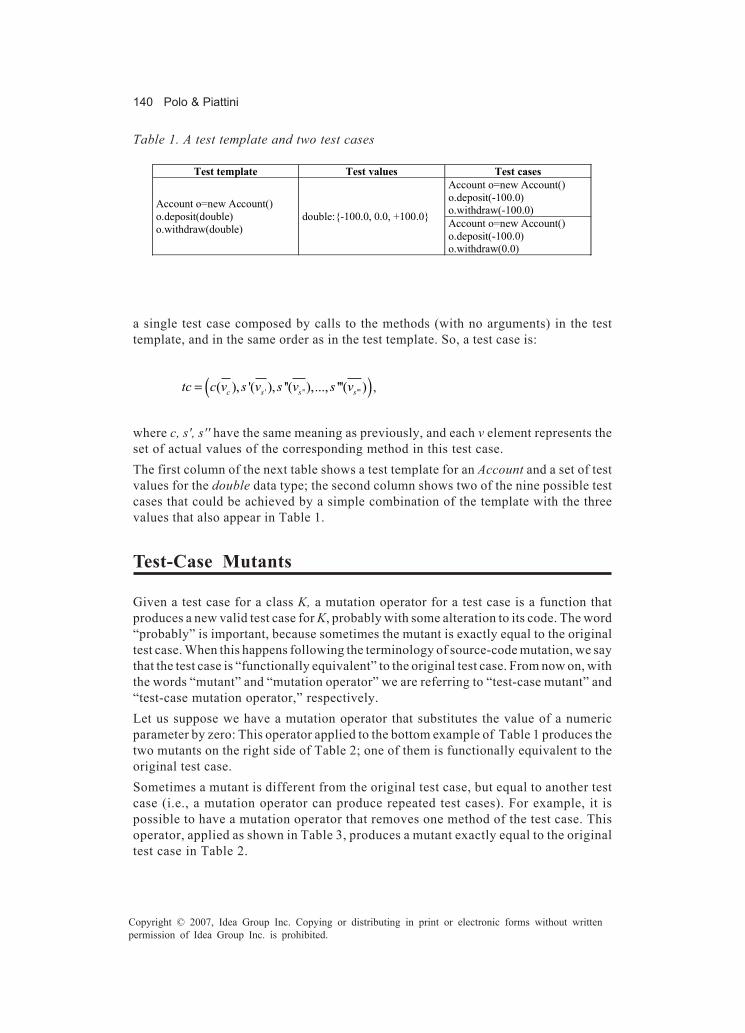
140 Polo & Piattini
Copyright © 2007, Idea Group Inc. Copying or distributing in print or electronic forms without writtenpermission of Idea Group Inc. is prohibited.
Test template Test values Test cases Account o=new Account() o.deposit(-100.0) o.withdraw(-100.0) Account o=new Account()
o.deposit(double) o.withdraw(double)
double:{-100.0, 0.0, +100.0} Account o=new Account() o.deposit(-100.0) o.withdraw(0.0)
Table 1. A test template and two test cases
a single test case composed by calls to the methods (with no arguments) in the testtemplate, and in the same order as in the test template. So, a test case is:
( )' '' '''( ), '( ), ''( ),..., '''( )c s s stc c v s v s v s v= ,
where c, s', s'' have the same meaning as previously, and each v element represents theset of actual values of the corresponding method in this test case.The first column of the next table shows a test template for an Account and a set of testvalues for the double data type; the second column shows two of the nine possible testcases that could be achieved by a simple combination of the template with the threevalues that also appear in Table 1.
Test-Case Mutants
Given a test case for a class K, a mutation operator for a test case is a function thatproduces a new valid test case for K, probably with some alteration to its code. The word“probably” is important, because sometimes the mutant is exactly equal to the originaltest case. When this happens following the terminology of source-code mutation, we saythat the test case is “functionally equivalent” to the original test case. From now on, withthe words “mutant” and “mutation operator” we are referring to “test-case mutant” and“test-case mutation operator,” respectively.Let us suppose we have a mutation operator that substitutes the value of a numericparameter by zero: This operator applied to the bottom example of Table 1 produces thetwo mutants on the right side of Table 2; one of them is functionally equivalent to theoriginal test case.Sometimes a mutant is different from the original test case, but equal to another testcase (i.e., a mutation operator can produce repeated test cases). For example, it ispossible to have a mutation operator that removes one method of the test case. Thisoperator, applied as shown in Table 3, produces a mutant exactly equal to the originaltest case in Table 2.

Test-Case Mutation 141
Copyright © 2007, Idea Group Inc. Copying or distributing in print or electronic forms without writtenpermission of Idea Group Inc. is prohibited.
Situations like those explained in the previous paragraph and table are not worrisome.The important issue is to keep under control the original test cases and their respectivemutants, as well as the states of the instances proceeding from the execution of theoriginal test case and from its respective mutants. This “control” is what makes it possibleto make comparisons and to know with exactitude what mutants are “killed.”
Mutation Operators
Mutation operators introduce some types of change in the sequence of operationscomposing test cases. shows the mutation operators we have defined. All of themproduce ways of using the class under test different than the original one that is providedby the original test case.
Killed, Alive, and Injured Mutants
Many software testing researchers and tools recommend or impose the implementation(or redefinition, if it is inherited and has a default implementation) of an equals methodin the class under test (Chen, Tse, & Chen, 2001; Doong & Frankl, 1994; JUnit, 2003).equals is particularly useful in testing because it allows the comparison of the state ofthe instance obtained by a test case with the state of the expected instance.
Table 2. Two mutants, one of them functionally equivalent to the original test case(Applying the Zero operator)
Original test case Mutants Account o=new Account() o.deposit(0.0) � o.withdraw(-100.0) Account o=new Account()
o.deposit(-100.0) o.withdraw(0.0) Account o=new Account()
o.deposit(-100.0) o.withdraw(0.0) �
Table 3. A mutant different from the original test case, but equal to the original test caseshown in Table 2 (Applied operator: Comment line)
Original test case Mutant Account o=new Account() o.deposit(-100.0) o.withdraw(0.0) o.deposit(100.0)
Account o=new Account() o.deposit(-100.0) o.withdraw(0.0) /* o.deposit(100.0) */

142 Polo & Piattini
Copyright © 2007, Idea Group Inc. Copying or distributing in print or electronic forms without writtenpermission of Idea Group Inc. is prohibited.
Table 5. A test case and an injured mutant (Applying the IN operator)
Original test case Mutant
Account o=new Account(); o.deposit(100); o.withdraw(100); The balance is zero.
Account o=new Account(); o.withdraw(100); o.deposit(100); The balance is zero, but an exception has been thrown after withdrawing.
Being t a test case, the expression f(t) denotes the state of the instance after executingthe test case t. Being m a mutant proceeding from t, we say that m is “killed” if and onlyif f(t) ≠ f(m); m is “injured” when f(t) = f(m), but methods in t have thrown differentexceptions than operations in m; m is “alive” when f(t) = f(m) and t and m have thrownthe same exceptions. The comparison of f(t) and f(m) by means of the “=” sign is madewith the equals operation which, in most cases, must be specifically redefined for theclass under test.Let us suppose that a banking account throws an exception when one attempts towithdraw and the balance is less than or equal to zero. After executing the constructorin Table 5, the account balance is zero; after executing the original test case, the accountbalance is zero and no exception has been produced. However, the account balance isalso zero after executing the mutant, but an exception has been thrown after the call towithdraw, which has caused the interruption of the execution, thus producing an injuredmutant.
Table 4. Mutation operators for test cases
Operator Description
CL (Comment Line) Comments on a method from the test case
IN (Interchange of calls) Interchanges the order of two calls to methods
PI (Parameter interchange) Interchanges two parameters of compatible types
RC (Repeat call) Repeats a call to a method
ZE (Zero) Substitutes a numeric parameter by zero, or changes a complex parameter by null
MAX (Maximum) Changes a numeric parameter by the maximum value of its corresponding data type
MIN (Minimum) Changes a numeric parameter by the minimum value of its corresponding data type
NEG (Negativize) Multiplies by –1 a numeric parameter
ADD (Addition) Adds 1 to a numeric parameter
SUB (Subtraction) Subtracts 1 from a numeric parameter

Test-Case Mutation 143
Copyright © 2007, Idea Group Inc. Copying or distributing in print or electronic forms without writtenpermission of Idea Group Inc. is prohibited.
As we said in the introduction, the test-case mutation technique is especially useful fortesting strongly constrained classes, which a banking account should be. If we pass validvalues to the parameters of the methods that compose the test cases of a correctlyimplemented strongly constrained class, we expect the class to kill and injure manymutants. If only a few mutants are killed and injured, then we should suspect that the classbeing tested has some kind of fault in its implementation.With invalid values, the correct implementation of a strongly constrained class shouldleave many mutants alive, because the execution of the test case will be interrupted earlydue to the exceptions thrown by operations in the test case.In general, the percentage of injured mutants depends on the position in the test caseof the operation that throws the exception.
Functionally Equivalent Mutants
A test case is a way of using the class being tested. We expect that the state of theinstances will be different depending on the way of using the class. This affirmation isrisky, since its truth will depend on the method’s implementation and on the class usageprotocol (which can be described by the method sequence specification). In the simpleexample of the Account class, the following test case and mutant put both instances inthe same state.However, most of these situations are due to the functional equivalence of the test caseand the mutant, as with the example shown in the previous table.Therefore, for each test case generated, we will count the number of its mutants killedand injured.
Experiments
This section presents some experiments we have made to validate our technique. First,we present them applied to the TriTyp program, commonly used as a benchmark forvalidating testing techniques. Second, a discussion of the results with other programsis presented.
Table 6. A test case and one of its mutants (Applying the IN operator)
Original test case Mutant Account a=new Account(); a.deposit(100.0); a.deposit(50.0);
Account a=new Account(); a.deposit(50.0); a.deposit(100.0);

144 Polo & Piattini
Copyright © 2007, Idea Group Inc. Copying or distributing in print or electronic forms without writtenpermission of Idea Group Inc. is prohibited.
Figure 1. Two versions of the TriTyp program
i : intj : intk : inttrityp : int
+ TriTyp2()+ setIJK(arg0 : int, arg1 : int, arg2 : int) : void+ type() : int+ equals(arg) : Object) : boolean+ toString() : String
TriTyp2(from paper)
i : intj : intk : inttrityp : int
+ TriTyp1()+ setI(arg0 : int) : void+ setJ(arg0 : int) : void+ setK(arg0 : int) : void+ type() : int+ equals(arg) : Object) : boolean
TriTyp1(from paper)
Application of the Technique to the TriTyp Program
The TriTyp program is commonly used as a benchmark for validating testing techniques.It receives as inputs three integers representing the lengths of the sides of a triangle, andmust answer whether the triangle is equilateral, isosceles, scalene or whether it is not atriangle.We have written two versions of the program, schematically shown in Figure 1. Bothversions have three integer fields corresponding to the lengths of the three sides, plusone additional field representing the triangle type, which is computed inside the typemethod. In both cases, we have redefined the equals method to return true if the twotriangles have the same values in the four fields (the three lengths and the type field).In TriTyp1, the side lengths are assigned using the methods setI, setJ, setK, which receivean integer parameter. If the received value is less than or equal to zero, they throw anexception, which interrupts the execution of the test case; otherwise, the receivedargument is assigned to the corresponding field. In TriTyp2, the three values areassigned using the setIJK method, which receives three integer values, throwing anexception if any of the three values is not valid.For both programs, original test cases consist of a call to the corresponding constructor,calls to the setter methods (to setI, setJ, setK in TriTyp1, and to setIJK in TriTyp2), anda call to the type method. In the first case, the order of the sequence has a relativeimportance, since the triangle type does not depend on the order of calls to setI, setJ, andsetK.We generated test cases for both programs using a set of positive values and a set ofzero and negative values. Zero and negative values are invalid arguments. Positivevalues are valid arguments (i.e., fulfill the argument precondition), but they may producean invalid triangle (for example, if the sum of two sides is equal to the third one).
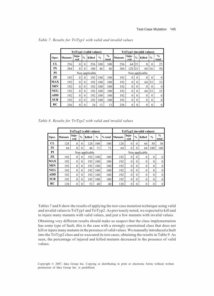
Test-Case Mutation 145
Copyright © 2007, Idea Group Inc. Copying or distributing in print or electronic forms without writtenpermission of Idea Group Inc. is prohibited.
Tables 7 and 8 show the results of applying the test-case mutation technique using validand invalid values to TriTyp1 and TriTyp2. As previously noted, we expected to kill andto injure many mutants with valid values, and just a few mutants with invalid values.Obtaining very different results should make us suspect that the class implementationhas some type of fault; this is the case with a strongly constrained class that does notkill or injure many mutants in the presence of valid values. We manually introduced a faultinto the TriTyp2 class and re-executed its test cases, obtaining the results in Table 9. Asseen, the percentage of injured and killed mutants decreased in the presence of validvalues.
Table 7. Results for TriTyp1 with valid and invalid values
Table 8. Results for TriTyp2 with valid and invalid values
TriTyp1 (valid values) TriTyp1 (invalid values)
Oper. Mutants Inju- red % Killed % %
total Mutants Inju- red % Killed % %
total CL 256 0 0 256 100 100 256 64 25 0 0 25 IN 384 0 0 180 46 46 384 128 33 64 16 50 PI Non applicable Non applicable ZE 192 0 0 192 100 100 192 0 0 0 0 0
MAX 192 0 0 192 100 100 192 0 0 64 33 33 MIN 192 0 0 192 100 100 192 0 0 0 0 0 NEG 192 0 0 192 100 100 192 0 0 64 33 33 ADD 192 0 0 192 100 100 192 0 0 0 0 0 SUB 192 0 0 192 100 100 192 0 0 0 0 0 RC 256 0 0 34 13 13 256 0 0 0 0 0
TriTyp2 (valid values) TriTyp2 (invalid values)
Oper. Mutants Inju- red % Killed % % total Mutants Inju-
red % Killed % % total
CL 128 0 0 128 100 100 128 0 0 64 50 50 IN 64 0 0 46 71 71 64 0 0 64 100 100 PI Non applicable Non applicable ZE 192 0 0 192 100 100 192 0 0 0 0 0
MAX 192 0 0 192 100 100 192 0 0 0 0 0 MIN 192 0 0 192 100 100 192 0 0 0 0 0 NEG 192 0 0 192 100 100 192 0 0 0 0 0 ADD 192 0 0 192 100 100 192 0 0 0 0 0 SUB 192 0 0 192 100 100 192 0 0 0 0 0 RC 128 0 0 52 40 40 128 0 0 0 0 0

146 Polo & Piattini
Copyright © 2007, Idea Group Inc. Copying or distributing in print or electronic forms without writtenpermission of Idea Group Inc. is prohibited.
Faulty implementation of TriTyp2
TriTyp2 (valid values) TriTyp2 (invalid values)
Oper. Mutants Inju- red % Killed % % total Mutants Inju-
red % Killed % % total
CL 256 0 0 64 25 25 256 64 25 64 25 50 IN 384 0 0 192 50 50 384 64 16 256 66 83 PI Non applicable Non applicable ZE 192 0 0 64 33 33 192 0 0 144 75 75
MAX 192 0 0 0 0 0 192 0 0 168 87 87 MIN 192 0 0 64 33 33 192 0 0 144 75 75 NEG 192 0 0 64 33 33 192 0 0 128 66 66 ADD 192 0 0 0 0 0 192 0 0 64 33 33 SUB 192 0 0 16 8 8 192 0 0 64 33 33 RC 256 0 0 0 0 0 256 0 0 0 0 0
Table 9. Results for a faulty implementation of TriTyp2, with valid and invalid values
Table 10. Results for a correct and a faulty version of the java.util.Stack class
Stack Regular expression: Stack().(pop()|push())*; Max length: 5; Number of test cases:
341
Right version Faulty version
Oper. Mutants Inju- red % Killed % % total Mutants Inju-
red % Killed % % total
CL 1252 0 0 918 73 73 1252 0 0 0 0 0 IN 1744 0 0 876 50 50 1744 0 0 0 0 0 ZE 939 0 0 606 64 64 939 0 0 0 0 0 RC 1252 0 0 852 68 68 1252 0 0 0 0 0
Other Experiments
Container classes have also been widely used to validate testing techniques (Ball,Hoffman, Ruskey, Webber, & White, 2000; Barnett & Schulte, 2002; Henkel & Diwan,2003; Hoffman, Strooper, & Wilkin, 2005), probably because its operations can be easilyannotated with constraints. With the same goal, we applied the test-case mutationtechnique to both several standard Java container classes and to versions of these sameclasses, in which we have manually introduced a fault.

Test-Case Mutation 147
Copyright © 2007, Idea Group Inc. Copying or distributing in print or electronic forms without writtenpermission of Idea Group Inc. is prohibited.
The Stack Class
The first sample corresponds to the java.util.Stack class, whose summary is shown inTable 10 (data corresponding to the nonapplicable operators have been removed). Wehave generated test cases (and their corresponding mutants) using the regular expres-sion Stack().(pop()|push())*. Results of this sample are especially notable, since nomutants died in the manipulated version, thus revealing the presence of a fault.
The LinkedList Class
The second experiment was carried out with the java.util.LinkedList class. In this case,we generated several families of test cases using the four short regular expressions listedin Table 11.One of the operations referenced by each regular expression contains, in the modifiedversion of the class, one single fault. The goal in this case was to check whether thetesting technique helps us to detect the presence of this fault.Table 12 shows the results of testing this class. Note that the second column referencesthe corresponding regular expression in the previous table and that results ofnonapplicable operators (those that produce no mutants) have been removed.The presence of the fault is clear for regular expressions (a) and (d), whereas the testengineer may have more doubts with cases (b) and (c), since the total percentages of killedand injured (although more correct than in the faulty version), are very similar. However,in these two cases, the number of killed mutants is zero and all the differences betweenthe original and muted test cases are in the injured ones. Thus, the hypothesis that a lownumber of killed mutants is a good predictor of the existence of faults seems plausible.
The Vector Class
The hypothesis mentioned in the last paragraph is also confirmed with another smallexperiment made with the java.util.Vector. In fact, as seen in Table 13, the faulty versionof the java.util.Vector class does not kill any mutants; the entire contribution to the totalpercentage comes from the injured mutants.
Table 11. Regular expressions used to test the java.util.LinkedList class
Regular expression
Max length
Number of test cases
LinkedList().add(Object)* 4 40 LinkedList ().add(int, Object)* 3 820 LinkedList ().add(Object)*.remove(int)* 3 26 LinkedList ().add(Object)*.remove(Object)* 4 39
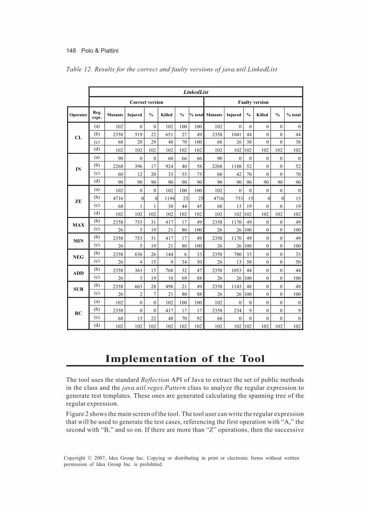
148 Polo & Piattini
Copyright © 2007, Idea Group Inc. Copying or distributing in print or electronic forms without writtenpermission of Idea Group Inc. is prohibited.
Table 12. Results for the correct and faulty versions of java.util.LinkedList
LinkedList
Correct version Faulty version
Operator Reg. expr. Mutants Injured % Killed % % total Mutants Injured % Killed % % total
(a) 102 0 0 102 100 100 102 0 0 0 0 0 (b) 2358 519 22 651 27 49 2358 1041 44 0 0 44 (c) 68 20 29 48 70 100 68 26 38 0 0 38
CL
(d) 102 102 102 102 102 102 102 102 102 102 102 102 (a) 90 0 0 60 66 66 90 0 0 0 0 0 (b) 2268 396 17 924 40 58 2268 1188 52 0 0 52 (c) 60 12 20 33 55 75 60 42 70 0 0 70
IN
(d) 90 90 90 90 90 90 90 90 90 90 90 90 (a) 102 0 0 102 100 100 102 0 0 0 0 0 (b) 4716 0 0 1194 25 25 4716 753 15 0 0 15 (c) 68 1 1 30 44 45 68 13 19 0 0 19
ZE
(d) 102 102 102 102 102 102 102 102 102 102 102 102 (b) 2358 753 31 417 17 49 2358 1170 49 0 0 49 MAX (c) 26 5 19 21 80 100 26 26 100 0 0 100 (b) 2358 753 31 417 17 49 2358 1170 49 0 0 49 MIN (c) 26 5 19 21 80 100 26 26 100 0 0 100 (b) 2358 636 26 144 6 33 2358 780 33 0 0 33 NEG (c) 26 4 15 9 34 50 26 13 50 0 0 50 (b) 2358 363 15 768 32 47 2358 1053 44 0 0 44 ADD (c) 26 5 19 18 69 88 26 26 100 0 0 100 (b) 2358 663 28 498 21 49 2358 1143 48 0 0 48 SUB (c) 26 2 7 21 80 88 26 26 100 0 0 100 (a) 102 0 0 102 100 100 102 0 0 0 0 0 (b) 2358 0 0 417 17 17 2358 234 9 0 0 9 (c) 68 15 22 48 70 92 68 0 0 0 0 0
RC
(d) 102 102 102 102 102 102 102 102 102 102 102 102
Implementation of the Tool
The tool uses the standard Reflection API of Java to extract the set of public methodsin the class and the java.util.regex.Pattern class to analyze the regular expression togenerate test templates. These ones are generated calculating the spanning tree of theregular expression.Figure 2 shows the main screen of the tool. The tool user can write the regular expressionthat will be used to generate the test cases, referencing the first operation with “A,” thesecond with “B,” and so on. If there are more than “Z” operations, then the successive

Test-Case Mutation 149
Copyright © 2007, Idea Group Inc. Copying or distributing in print or electronic forms without writtenpermission of Idea Group Inc. is prohibited.
ones are mapped to combinations of letters starting with “(AA),” “(AB) ,” and so on. Theregular expression in the example (AF{1,3}) will generate test cases starting with thejava.util.LinkedList() constructor, followed by from 1 to 3 calls to add(Object).Test templates must be combined with actual values and additional code to produce thetesting methods in the generated testing class. Test values must be manually assignedto parameters by the user, for which he or she can apply his or her best knowledge about
Table 13. Results for the java.util.Vector class
Vector Regular expression: ().add(Object)*.remove(int)*; Max. length: 4; Number of test
cases: 547
Correct version Faulty version
Oper. Mutants Inju- red % Killed % % total Mutants Inju-
red % Killed % % total
CL 2004 408 20 1110 55 75 384 102 26 0 0 26 IN 2781 471 16 1365 49 66 351 177 50 0 0 50 ZE 2004 104 5 1032 51 56 384 68 17 0 0 17
MAX 1002 333 33 183 18 51 192 102 53 0 0 53 MIN 1002 333 33 183 18 51 192 102 53 0 0 53 NEG 1002 218 21 126 12 34 192 68 35 0 0 35 ADD 1002 213 21 267 26 47 192 102 53 0 0 53 SUB 1002 276 27 213 21 48 192 102 53 0 0 53 RC 2004 162 8 1023 51 59 384 0 0 0 0 0
Figure 2. Main screen of the tool

150 Polo & Piattini
Copyright © 2007, Idea Group Inc. Copying or distributing in print or electronic forms without writtenpermission of Idea Group Inc. is prohibited.
Figure 3. Values assignment
the system, as well as limit the values of assertions, which has been suggested in manystudies (Boyapati, Khurshid, & Marinov, 2002; Korel & Al-Yami, 1996; Offut, Liu,Abdurazik, & Amman, 2003; Tracey, Clark, Mander, & McDermid, 2000; Tse & Xu, 1996).Testing values for arguments of primitive data types are given by hand, using the windowshown in Figure 3. Moreover, it is also possible to add pre- and postcode to the test cases,in order to provide the user with the possibility of having a greater control over test cases.Values of nonprimitive data types must be previously serialized. Later, they will be readfrom the corresponding files and passed as parameters to the operations in the test cases.The mix of test templates and test values is a file containing testing methods, both originaland mutant. When compiled and executed, this program builds a wide set of objects,which are serialized and saved on the disk Then, a result analyzer compares them, writingthe results in a XML file and showing a summary table (Figure 4).
Conclusion
This chapter has presented a new testing technique called test-case mutation, whosemain goal is to help the test engineer find faults in software. The initial idea is to considera test case as a way of using the class being tested, and then to assume that to use theclass in a different way will produce different results. Obviously, maintaining control ofthe “original” and the “other” ways of use is central. Each different way of use comesfrom the original one when a test-case-mutation operator is applied, which introducesa small change in the original test case.The technique has been shown to be valid for some common problems in softwareliterature. However, still more work and experimental results are required to validate it.Besides this, we are also working on the definition of new mutation operators.

Test-Case Mutation 151
Copyright © 2007, Idea Group Inc. Copying or distributing in print or electronic forms without writtenpermission of Idea Group Inc. is prohibited.
Test-case mutation does not require knowledge of the source code, making it a validtechnique for testing components or Web services, when the component user knowsonly the set of services offered through its interface.Test-case mutation and source-code mutation are very different: besides working withdifferent artifacts (test cases versus source code), the goal of this one is to check thequality of test cases (the percentage of killed mutants is considered a coverage criteriaof the original program), whereas the goal of test-case mutation is to detect the presenceof faults in the program. Test-case mutation is an inexpensive testing technique, whenan automatic generator is used. Moreover, applying the concepts presented earlier in thischapter, such as regular expressions, reflection and serialization, whose inclusion is nowstandardized in the most used programming languages, it is not too difficult to write agenerator as an standalone or a plugin for an IDE.
Figure 4. Result file (top) and result analyzer (bottom)
152 Polo & Piattini
Copyright © 2007, Idea Group Inc. Copying or distributing in print or electronic forms without writtenpermission of Idea Group Inc. is prohibited.
References
Ball, T., Hoffman, D., Ruskey, F., Webber, R., & White, L. (2000). State generation andautomated class testing. Software Testing, Verification and Reliability, 10, 149-170.
Barnett, M., & Schulte, W. (2002). Contracts, components and their runtime verificationon the .NET platform (Tech. Rep. No. MSR-TR-2002-38). Microsoft Research.
Baudry, B., Fleurey, F., Jézéquel, J. M., & Traon, Y. L. (in press). From genetic tobacteriological algorithms for mutation-based testing. In Software testing, verifi-cation and reliability.
Boyapati, C., Khurshid, S., & Marinov, D. (2002). Korat: Automated testing based onJava predicates. Paper presented at the ACM International Symposium on Soft-ware Testing and Analysis (ISSTA).
Chen, H. Y., Tse, T. H., & Chen, T. Y. (2001). TACCLE: A methodology for object-orientedsoftware testing at the class and cluster levels. ACM Transactions on SoftwareEngineering and Methodology, 10(4), 56-109.
Choi, B., Mathur, A., & Pattison, B. (1989). PMothra: Scheduling mutants for executionon a hypercube. Paper presented at the Proceedings of the ACM SIGSOFT ’89 ThirdSymposium on Software Testing, Analysis, and Verification, Key West, FL.
Doong, R. K., & Frankl, P. G. (1994). The ASTOOT approach to testing object-orientedprograms. ACM Transactions on Software Engineering and Methodology, 3(2),101-130.
Duncan, I. M. (1993). Strong mutation testing strategies. University of Durham, UK.Henkel, J., & Diwan, A. (2003). Discovering algebraic specifications from Java classes.
Paper presented at the 17th European Conference on Object-Oriented Programming(ECOOP).
Hirayama, M., Yamamoto, T., Okayasu, J., Mizuno, O., & Kikuno, T. (2002, October 3-4).Elimination of crucial faults by a new selective testing method. Paper presentedat the International Symposium on Empirical Software Engineering (ISESE2002),Nara, Japan.
Hoffman, D., Strooper, P., & Wilkin, S. (2005). Tool support for executable documentationof Java class hierarchies. Software Testing, Verification and Reliability, in press(available from Wiley Digital Library).
Howden, W. E. (1982). Weak mutation testing and completeness of test sets. IEEETransactions on Software Engineering, 8(4), 371-379.
JUnit (2003). JUnit, Testing Resources for Extreme Programming. Retrieved January 5,2003, from http://www.junit.org
Kim, S. W., Clark, J. A., & McDermid, J. A. (2001). Investigating the effectiveness ofobject-oriented testing strategies using the mutation method. Software Testing,Verification and Reliability, 11, 207-225.
Kirani, S., & Tsai, W. T. (1994). Method sequence specification and verification ofclasses. Journal of Object-Oriented Programming, 7(6), 28-38.

Test-Case Mutation 153
Copyright © 2007, Idea Group Inc. Copying or distributing in print or electronic forms without writtenpermission of Idea Group Inc. is prohibited.
Korel, B., & Al-Yami, A. (1996). Assertion-oriented automated test data generation.Paper presented at the International Symposium on Software Testing and Analysis(ISSTA1998), Clearwater Beach, FL.
Krauser, E. W., Mathur, A. P., & Rego, V. J. (1991). High performance software testingon SIMD machine. IEEE Transactions on Software Engineering, 17(5), 403-423.
Ma, Y. S., Offutt, J., & Kwon, Y. R. (2004). MuJava: An automated class mutation system.In Software Testing, Verification and Reliability, in press (available from WileyDigital Library).
Mathur, A. P. (1991, September). Performance, effectiveness, and reliability issues insoftware testing. Paper presented at the Proceedings of the 15th Annual Interna-tional Computer Software and Applications Conference, Tokyo, Japan.
Mresa, E. S., & Bottaci, L. (1999). Efficiency of mutation operators and selective mutationstrategies: An empirical study. Software Testing, Verification and Reliability, 9,205-232.
Offutt, J., & Lee, S. D. (1994). An empirical evaluation of weak mutation. IEEE Transac-tions on Software Engineering, 20(5), 337-344.
Offut, J., Liu, S., Abdurazik, A., & Amman, P. (2003). Generating test data from state-basedspecifications. Software Testing, Verification and Reliability, (13), 25-53.
Offut, J., & Pan, J. (1997). Automatically detecting equivalent mutants and infeasiblepaths. Software Testing, Verification and Reliability, 7, 165-192.
Offut, J., Rothermel, G., Untch, R. H., & Zapf, C. (1996). An experimental determinationof sufficient mutant operators. ACM Transactions on Software Engineering andMethodology, 5(2), 99-118.
Tracey, N., Clark, J., Mander, K., & McDermid, J. (2000). Automated test data generationfor exception conditions. Software: Practice and Experience, 30(1), 61-79.
Tse, T., & Xu, Z. (1996). Test case generation for class-level object-oriented testing.Paper presented at the 9th International Software Quality Week, San Francisco.
Weiss, S. N., & Fleyshgakker, V. N. (1993, June). Improved serial algorithms for mutationanalysis. Paper presented at the International Symposium on Software Testing andAnalysis (ISSTA), Cambridge, MA.
Wong, W. E., & Mathur, A. P. (1995). Reducing the cost of mutation testing: An empiricalstudy. Journal of Systems and Software, 31(3), 185-196.
154 Abu-Taieh & El Sheikh
Copyright © 2007, Idea Group Inc. Copying or distributing in print or electronic forms without writtenpermission of Idea Group Inc. is prohibited.
Chapter VIII
Discrete EventSimulation Process
Validation, Verification,and Testing
Evon M. O. Abu-Taieh, The Arab Academyfor Banking and Financial Sciences, Jordan
Asim Abdel Rahman El Sheikh, The Arab Academyfor Banking and Financial Sciences, Jordan
Abstract
This chapter introduces validation, verification, and testing tools and techniquespertaining to discrete event simulation. The chapter distinguishes between validationand verification within the context of discrete event simulation. Then, we will show theimportance of such topic by revealing the amount research done in simulationvalidation and verification. The chapter subsequently discusses the reasons whysimulation projects fail and the sources of simulation inaccuracies. Next, the chaptergives different taxonomies for validation, verification, and testing techniques (VV&T)for both types of simulation systems: object-oriented-based and algorithmic-based.Therefore, the chapter will present a translation of thirteen software-engineeringpractices suggested for simulation projects. Notwithstanding the significance ofproviding an objective assessment platform, as such, the chapter will shed light on theindependence of VV&T pertaining to simulation systems.
Discrete Event Simulation Process Validation, Verification, and Testing 155
Copyright © 2007, Idea Group Inc. Copying or distributing in print or electronic forms without writtenpermission of Idea Group Inc. is prohibited.
Introduction
Simulation software systems have certain characteristics that make them different fromother software systems, consequently, and due to the special nature of simulation-software systems; VV&T techniques of simulation systems must be looked at closely.First, the chapter makes the distinction between validation and verification pertainingto simulation systems. Then, the chapter shows the motivation for VV&T in simulationthrough two ways:First is the different nature of the VV&T in simulation-softwaresystems. The second is showing the amount of research done in VV&T of simulation-software systems, which only emphasizes the importance of such topic. The chaptersubsequently discusses the why simulation projects fail and the sources of simulationinaccuracies. Thus, the chapter gives different taxonomies for VV&T for both types ofsimulation systems: object-oriented-based and algorithmic-based. Therefore, the chap-ter will present a translation of thirteen software-engineering practices suggested forsimulation projects. Notwithstanding the significance of providing an objective assess-ment platform, as such, the chapter will shed light on the aspect of the independence ofVV&T pertaining to simulation. Finally, the chapter highlights some future trends in theautomation of VV&T.
V&V Definition and Distinction
In order to be able to discuss V&V, they must first be based on their original definition,which fully comprehends the true denotation of V&V as related to simulation systems.Sommerville (2001) defines validation by raising the question “are we building the rightproduct?”(p. 420), while defining verification by raising another question “are webuilding the product right?” (p. 420). This comes from a pure software-engineering pointof view, noting that the simulation perspective on the definitions of V&V are similar yetnot the same. On another note, Pidd (1998) defines validation as “a process whereby weasses the degree to which the lumped model input: output relation map onto those realsystems” (p. 157).Likewise, Pidd (1998) distinguishes validation from verification by referring to verifica-tion as “a process by which we try to assure ourselves that the lumped model is properlyreleased in the computer program. The Lumped model is defined as an explicit andsimplified version of the base model and is the one which will be used in managementscience” (p. 157). While Smith (1998) paraphrases validation as answering the question“Are we building the right product?” (p. 806) and verification as answering the question,“Are we building the product right?” (p. 806), Balci, (1995, 2003), Banks (1999), andKleignen, Bettonvil, and Gmenendahl (1996) define model validation as follows:
Model validation is substantiating that the model, within its domain of applicability,behaves with satisfactory accuracy consistent with the study objectives. Model validationdeals with building the right model. It is conducted by running the model under the“same” input conditions that drive the system and by comparing model behavior withthe system behavior. (Balci, 1995, p. 147)

156 Abu-Taieh & El Sheikh
Copyright © 2007, Idea Group Inc. Copying or distributing in print or electronic forms without writtenpermission of Idea Group Inc. is prohibited.
Balci (1995) defined validation as true simulation science when stressing the wordsdomain and satisfactory. Also Balci (1995) defines model verification as in the followingquote:
Model verification is substantiating that the model is transformed from one form intoanother, as intended, with sufficient accuracy. Model verification deals with buildingthe model right. The accuracy of transforming a problem formulation into a modelspecification or the accuracy of converting a model representation in micro flowchartinto an executable computer program is evaluated in model verification. (p. 147)
Again Balci’s (1995) definition is stressing here sufficient accuracy. Then Balci definesmodel testing as follows:
Model testing is demonstrating that inaccuracies exist or revealing the existence oferrors in the model. In model testing, we subject the model to test data or test cases tosee if it functions properly. “Test failed” implies the failure of the model, not the test,Testing is conducted to perform validation and verification. (p. 147)
As such, the mere distinction between verification and validation is minute yet substan-tive, acknowledging that validation ensures that the product caters to the needs,whereas, verification ensures the correctness and aptness of the product. Within thiscontext the word testing would be the tool to examine these two aspects.
Motivation for V&V in Simulation
Defining simulation in its broadest aspect as embodying a certain model to represent thebehavior of a system, whether that may be an economic or an engineering one, with whichconducting experiments is attainable. Such a technique enables the management, whenstudying models currently used, to take appropriate measures and make fitting decisionsthat would further complement today’s growth sustainability efforts, apart from costdecrease, as well as service delivery assurance. As such, the computer-simulationtechnique contributed in cost decline; depicting the “cause & effect”, pinpointing task-oriented needs or service-delivery assurance, exploring possible alternatives, identify-ing problems, as well as, proposing streamlined measurable and deliverable solutions,providing the platform for change strategy introduction, introducing potential prudentinvestment opportunities, and finally providing safety net when conducting trainingcourses. Yet, the simulation-development process is hindered due to many reasons. Likea rose, computer-simulation technique, does not exist without thorns; of which thelength, as well as, the communication during the development life cycle. Simulationreflects real-life problems; hence, it addresses numerous scenarios with a handful ofvariables. Not only is it costly, as well as, liable for human judgment, but also, the resultsare complicated and can be misinterpreted.

Discrete Event Simulation Process Validation, Verification, and Testing 157
Copyright © 2007, Idea Group Inc. Copying or distributing in print or electronic forms without writtenpermission of Idea Group Inc. is prohibited.
Within this context, there are four characteristics that distinguish simulation from anyother software-intensive work, which also make VV&T for simulation distinct from VV&T for other software, following are the four characteristics, as discussed by Page andNance (1997):
• Time as index variable: In simulation there is an indexing variable called TIME. Indiscrete event simulation (DES), this indexing variable “establishes an ordering ofbehavioral events” (Page & Nance, 1997, p. 91).
• Correctness of simulation software: In software engineering, correctness is oneof the objectives like reliability, maintainability, testability, and so on. Yet theObjective of correctness is very special to simulation software for the simple reasonHow useful is a simulation program “if questions remain concerning its validity”(Page & Nance, 1997, p. 91).
• Computational intensiveness: In their paper Page and Nance (1997) clearly statethat:
The importance of execution efficiency persists as a third distinctive characteristic.While model development costs are considerable, as is the human effort throughout theperiod of operation and use, the necessity for repetitive sample generation for statisticalanalysis and the testing of numerous alternatives forces concerns for executionefficiency that are seen in few software-intensive projects. (p. 91)
• Uses of simulation: Ihe uses of simulation are not typical, in fact there is “No typicaluse for simulation can be described” (Page & Nance, 1997, p. 91).
Within this context, the chapter attempts to shed the light on validation and verificationmethods and techniques that relate to simulation, which were discussed through 116research papers in the Winter Simulation Conference (WSC) over the years 1997 through2004 as seen in and Figure 1, such numbers indicate clearly the importance, inimitable,and unique case of validation and verification of simulation software.
Table 1. Published research of V&V in WSC
Year V & V Papers Total Published Papers % 1997 15 280 5% 1998 22 236 9% 1999 26 244 11% 2000 19 280 7% 2001 15 224 7% 2002 1 119 1% 2003 12 263 5% 2004 6 280 2% Total 116 1,926 6%

158 Abu-Taieh & El Sheikh
Copyright © 2007, Idea Group Inc. Copying or distributing in print or electronic forms without writtenpermission of Idea Group Inc. is prohibited.
It is worth noting that VV&T — as well as experimentations, execution, and design areso important that Shannon (1998) suggested allowing 40% of the project time for thesesteps.
Why Simulation Projects Fail
The arising issue of simulation projects falling short to be labeled as successful can beattributed to many reasons, an answer by Robinson (1999) had been put forth, as he listedthree main reasons; the first being “poor salesmanship when introducing the idea to anorganization” (p. 1702) which includes too much hope in too little time, while identifyingthe second reason as “lack of knowledge and skills particularly in statistics, experimentaldesign, the system being modeled and the ability to think logically” (p. 1702), andpinpointing the third reason as “lack of time to perform a study properly” (p. 1702).Nevertheless, simulation inaccuracy has become a recurrent condition that instigated athorough query in its sources.
Sources of Simulation Inaccuracy
There are three sources of inaccuracy in the simulation project might be developingduring the three major steps that are in the simulation life cycle, namely: modeling, dataextraction, and experimentation (see Figure 2).
Figure 1. V&V research papers in WSC
0
50
100
150
200
250
300
Number of Res. Papers
1997 1998 1999 2000 2001 2002 2003 2004 Years
% Total Published Papers V & V Papers
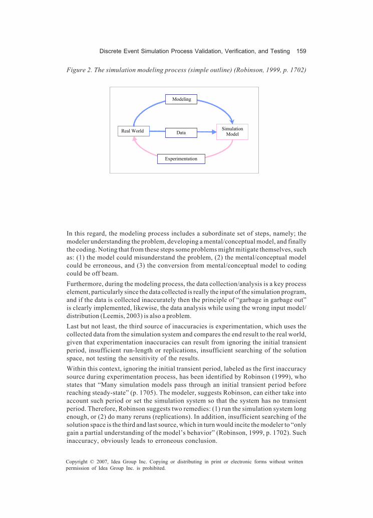
Discrete Event Simulation Process Validation, Verification, and Testing 159
Copyright © 2007, Idea Group Inc. Copying or distributing in print or electronic forms without writtenpermission of Idea Group Inc. is prohibited.
In this regard, the modeling process includes a subordinate set of steps, namely; themodeler understanding the problem, developing a mental/conceptual model, and finallythe coding. Noting that from these steps some problems might mitigate themselves, suchas: (1) the model could misunderstand the problem, (2) the mental/conceptual modelcould be erroneous, and (3) the conversion from mental/conceptual model to codingcould be off beam.Furthermore, during the modeling process, the data collection/analysis is a key processelement, particularly since the data collected is really the input of the simulation program,and if the data is collected inaccurately then the principle of “garbage in garbage out”is clearly implemented, likewise, the data analysis while using the wrong input model/distribution (Leemis, 2003) is also a problem.Last but not least, the third source of inaccuracies is experimentation, which uses thecollected data from the simulation system and compares the end result to the real world,given that experimentation inaccuracies can result from ignoring the initial transientperiod, insufficient run-length or replications, insufficient searching of the solutionspace, not testing the sensitivity of the results.Within this context, ignoring the initial transient period, labeled as the first inaccuracysource during experimentation process, has been identified by Robinson (1999), whostates that “Many simulation models pass through an initial transient period beforereaching steady-state” (p. 1705). The modeler, suggests Robinson, can either take intoaccount such period or set the simulation system so that the system has no transientperiod. Therefore, Robinson suggests two remedies: (1) run the simulation system longenough, or (2) do many reruns (replications). In addition, insufficient searching of thesolution space is the third and last source, which in turn would incite the modeler to “onlygain a partial understanding of the model’s behavior” (Robinson, 1999, p. 1702). Suchinaccuracy, obviously leads to erroneous conclusion.
Real World Simulation Model
Modeling
Data
Experimentation
Figure 2. The simulation modeling process (simple outline) (Robinson, 1999, p. 1702)

160 Abu-Taieh & El Sheikh
Copyright © 2007, Idea Group Inc. Copying or distributing in print or electronic forms without writtenpermission of Idea Group Inc. is prohibited.
Figure 3. Balci’s principles for VV&T (Balci, 1995, pp. 149-151)
Principle 1: The VV&T must be conducted throughout the entire life cycle of a simulation
study. Principle 2: The outcome of simulation model VV&T should not be considered as a binary
variable where the model is absolutely correct or absolutely incorrect. Principle 3: A simulation model is built with respect to the study objectives and its credibility is
judged with respect to those objectives. Principle 4: Simulation-model VV&T requires independence to prevent developer’s bias. Principle 5: Simulation-model VV&T is difficult and requires creativity and insight. Principle 6: Simulation-model credibility can be claimed only for the prescribed conditions for
which the model is tested. Principle 7: Complete simulation model testing is not possible. Principle 8: Simulation model VV&T must be planned and documented. Principle 9: Type I, II, and III errors must be prevented. Principle 10: Errors should be detected as early as possible in the life cycle of a simulation study. Principle 11: Multiple-response problems must be recognized and resolved properly. Principle 12: Successfully testing each submodel does not imply overall model credibility. Principle 13: Double-validation problems must be recognized and resolved properly. Principle 14: Simulation-model validity does not guarantee the credibility and acceptability of
simulation results. Principle 15: Formulated-problem accuracy greatly affects the acceptability and credibility of
simulation results.
If one acknowledges that errors in the simulation world clearly do not originate only fromone source, VV&T are not only considered a necessity but also imperative and crucial.Osman Balci, the well known simulation scientist, declared 15 principles, stated in Figure3, demonstrating the fundamentality and inevitability of conducting VV&T in thesimulation world.
VV&T Techniques
As seen in Balci’s fifth principle, VV&T for simulation models is “difficult and requirescreativity and insight” (Balci, 1995, p.149), yet the fact remains that “there are no step-by-step procedures available to guide the modeler in performing these important tasks”(Sadowski, 1991, p. 95). It is worth mentioning, however, that many have suggestedVV&T techniques and automated tools (Yilmaz, 2001) drawn mainly from software-engineering VV&T techniques like Balci (1994, 1997), Hoffer, George, and Valacich (2005),Pressman (2005), and many more. This is particularly true of Balci (1994), where in hisresearch, he has suggested a taxonomy of 45 V&V techniques, moreover, in anotherpaper, Balci (1997) defined 77 V&V techniques and 38 V&V techniques for object-oriented simulation.Highlighting the fact that the interest of this chapter is V&V techniques pertaining tosimulation, in this regard, the Balci taxonomy should be further reviewed. Balci (1994)categorized 45 VV&T techniques into: informal, static, dynamic, symbolic, constraint,and formal. Later he categorized 115 VV&T techniques to three families: conventional,adaptive, and specific VV&T (Balci, 1997), of which 77 VV&T techniques for conven-

Discrete Event Simulation Process Validation, Verification, and Testing 161
Copyright © 2007, Idea Group Inc. Copying or distributing in print or electronic forms without writtenpermission of Idea Group Inc. is prohibited.
tional simulation were again categorized into informal, static, dynamic, and formal. Theremaining 38 VV&T techniques, categorized into the adaptive and specific families, wereto be used in object-oriented simulation. Nevertheless, others like Hoffer et al. (2005) andPressman (2005) categorized the VV&T techniques based on the life-cycle phase. Next,both of Balci’s categorizations will be discussed thoroughly.The first taxonomy (Figure 4) of Balci had come before the object-oriented simulationidea, in which the 45 VV&T techniques were categorized: informal, static, dynamic, and
Figure 4. Taxonomy of VV&T techniques (Balci, 1995, p. 152)
Stat
ic
Dyn
amic
Sy
mbo
lic
Con
stra
int
Form
al
Info
rmal
Bla
ck-B
ox T
estin
g B
otto
m-U
p Te
stin
g D
ebug
ging
Ex
ecut
ion
Mon
itorin
g Ex
ecut
ion
Prof
iling
Ex
ecut
ion
Trac
ing
Fiel
d Te
sting
G
raph
ical
Com
paris
ons
Pred
ictiv
e V
alid
atio
n R
egre
ssio
n Te
stin
g Se
nsiti
vity
Ana
lysi
s St
atis
tical
Tec
hniq
ues
Stre
ss T
estin
g Su
bmod
el T
estin
g Sy
mbo
lic D
ebug
ging
To
p-D
own
Testi
ng
Vis
ualiz
atio
n W
hite
-Box
Tes
ting
Ass
ertio
n C
heck
ing
Bou
ndar
y A
naly
sis
Indu
ctiv
e A
sser
tions
Indu
ctio
n In
fere
nce
Lam
da C
alcu
lus
Logi
cal D
educ
tion
Pred
icat
e C
alcu
lus
Pred
icat
e Tr
ansf
orm
atio
n Pr
oof o
f Cor
rect
ness
Cau
se-E
ffec
t Gra
phin
g Pa
rtitio
n A
naly
sis
Path
Ana
lysi
s Sy
mbo
lic E
xecu
tion
Con
sist
ency
Che
ckin
g D
ata
Flow
Ana
lysi
s G
raph
-Bas
ed A
naly
sis
Sem
antic
Ana
lysi
s St
ruct
ural
Ana
lysis
Sy
ntax
Ana
lysi
s
Aud
it D
esk
Che
ckin
g Fa
ce V
alid
atio
n In
spec
tions
R
evie
ws
Turin
g Te
st
Wal
kthr
ough
s
Val
idat
ion,
Ver
ifica
tion,
and
Tes
ting
Tec
hniq
ues

162 Abu-Taieh & El Sheikh
Copyright © 2007, Idea Group Inc. Copying or distributing in print or electronic forms without writtenpermission of Idea Group Inc. is prohibited.
symbolic. Within this context, the informal VV&T technique includes tools and ap-proaches that “relay heavily on human reasoning” (Balci, 1994, p. 217) rather than“mathematical formalism” (Balci, 1994, p. 217), this category includes: audit, deskchecking, inspection, reviews, turing test, walkthroughs, given the fact that the wordinformal should not reflect lack of structure or formal guidelines as Balci (1994) says.In the same token, static VV&T techniques concentrate on the source code of the modeland need not the execution of the code (Hoffer, et al., 2005). More importantly, Balci (1994)has stated that automated tools and language compilers rely on this type of VV&T , sincethe static VV&T techniques category is comprised of: consistency checking, data-flowAnalysis, graph-based analysis, semantic analysis, structural analysis, and syntaxanalysis.Whereas, the dynamic VV&T technique’s distinguishing characteristic is for the modelexecution to evaluate the model as Balci (1994) states, as this category comprises of thefollowing VV&T techniques: black-boxing, bottom-up testing, debugging, executionmonitoring, execution profiling, execution tracing, field testing, graphical comparisons,predictive validation, regression testing, sensitivity analysis, statistical techniques,stress testing, submodel testing, symbolic debugging, top-down testing, visualization,and white-box testing. Nonetheless, the symbolic VV&T techniques category has beenused to asses the model using VV&T techniques like cause-effect graphing, partitionanalysis, path analysis, and symbolic execution, noting that later in Balci (1997), thiscategory was incorporated with static category and dynamic category, while cause-effect graphing, and symbolic execution were incorporated in the static category,partition analysis and path analysis were incorporated in the dynamic category. Onanother note, Balci (1994) has stated that “Constraint VV&T techniques are employedto assess model correctness using assertion checking, boundary analysis, and inductiveassertions” (p. 218). Later, however, such a category also disappeared and was incor-porated with others.Balci (1994), among others, admits that formal VV&T techniques are based on mathemati-cal proof, stating that “Current state-of-the-art formal proof of correctness techniquesare simply not capable of being applied to even a reasonably complex simulation model”(p. 218).Given the aforementioned, an elaborated overview will be subsequently given about agroup of VV&T techniques, taking into consideration the simulation standpoint.
Conventional SimulationVV&T Techniques
Audit
Zammit (2005), along with many, has considered audits as external type review, whileothers have classified it as informal VV&T like Balci (1994), either way, the purpose of

Discrete Event Simulation Process Validation, Verification, and Testing 163
Copyright © 2007, Idea Group Inc. Copying or distributing in print or electronic forms without writtenpermission of Idea Group Inc. is prohibited.
audit is to substantiate that the system performance meets the requirements, in order toexamine the actual code and supporting materials. As such, there are two types of audits:functional configuration audit and physical configuration audit (Zammit, 2005).
Inspections
Balci (1994, 1997) has repeatedly classified inspections as informal type of VV&T, yet,Zammit (2005) has classified tem as review type, nonetheless, the main goal of inspec-tions is to “manually examine code for occurrences of well-known errors,” noting thatcode inspection can detect 60% to 90% of “all software defects as well as provideprogrammers with feedback that enables them to avoid making the same type of errorsin the future work” (Hoffer et al., 2005, p. 576).
Face Validity
Balci (1994, 1997) has recurrently classified face validity additionally as informal type ofVV&T, although Sargent (2003) has stated that the goal in face validity is to ask“individuals knowledgeable about the system whether the model and/or its behavior isreasonable” (p. 41), yet Sargent (2003) has suggested questions, such as: “is the logicin the conceptual model correct?” (p. 41). And “is the model’s input-output relationshipsreasonable?”(p. 41), moreover, Banks, Carson, Nelson, and Nicol (2001) has suggestedthat sensitivity analysis can be used to check the model validity.
Structured Walkthrough
Balci (1994, 1997) has repeatedly classified structured walkthrough as an informal typeof VV&T, yet Zammit (2005) has classified it as review type, however, Hoffer et al. (2005)has stated that structured walkthrough can be used to review many system-develop-ment deliverables, including logical and physical as well as code, additionally Hoffer etal. explains that since walkthroughs tend to be informal, which in turn makes theprogrammer less apprehensive about walkthroughs and increase their frequency. Fur-thermore, it is recommended that walkthroughs to be done on smaller pieces of code,particularly since the longer the code the more defensive the programmer becomes, yetit is worth mentioning that the intention of walkthrough is not fixing the errors, butpointing them out. In this regard, Hoffer et al. gives a guideline for conductingwalkthrough in Figure 5.
Desk Checking
Balci (1994, 1997) has also classified desk checking as informal type of VV&T. Balci notesthat desk checking is an informal process, as confirmed additionally by Hoffer et al.

164 Abu-Taieh & El Sheikh
Copyright © 2007, Idea Group Inc. Copying or distributing in print or electronic forms without writtenpermission of Idea Group Inc. is prohibited.
Figure 5. Steps in a typical walkthrough (Hoffer et al., 2005, p. 577)
GUIDELINES FOR CONDUCTING A CODE WALKTHROUGH: 1. Have the review meeting chaired by the project manager or chief
programmer who is also responsible for scheduling the meeting, reserving a room, setting the agenda, inviting participants, and so on.
2. The programmer presents his or her work to the reviewers. Discussion should be general during the presentation.
3. Following the general discussion, the programmer walks through the code in detail, focusing on the logic of the code rather than on specific test cases.
4. Reviewers ask to walk through specific test cases. 5. The chair resolves disagreements if the review team cannot reach
agreement among themselves and assign duties, usually to the programmer, for making specific changes.
6. A second walkthrough is then scheduled if needed.
(2005), in which the programmer or someone else who understands the logic of theprogram works through the code with paper and pencil. The programmer executes eachinstruction, using test cases that may or may not be written down. In a sense, the revieweracts as the computer, mentally checking each step and its results for the entire set ofcomputer instructions.
Syntax Analysis
Balci (1994, 1997) has classified syntax analysis as a static VV&T technique that takesplace during the programming phase in the software-development lifecycle (Balci, 1994,1997). Moreover, the task of syntax analysis is distinctively differentiated, as stated inSebesta’s (2003) book Concepts of Programming Languages.Most compilers separate the task of analyzing syntax into two distinct parts: lexicalanalysis and syntax analysis. The lexical analyzer deals with small-scale languageconstructs, such as name and numeric literals. It is an essential pattern matcher. Thesyntax analyzer deals with the large-scale constructs, such as expressions, statements,and program unitsHoffer et al.’s (2005) statement that “Syntax checking is typically done by compiler.Errors in syntax are uncovered but the code is not executed” (p. 578), explains that syntaxchecking is an automated and static technique, where, “static testing means that the codebeing tested is not executed” (p. 578).
Discrete Event Simulation Process Validation, Verification, and Testing 165
Copyright © 2007, Idea Group Inc. Copying or distributing in print or electronic forms without writtenpermission of Idea Group Inc. is prohibited.
Reviews
Much like walkthrough, the main goal of reviews is to substantiate, to both managementas well as sponsors, that the project is conducted in accordance with the study’sobjectives, ensuring attainment of appropriate quality level. Highlighting the fact thatreviews are more interested in specifications and design deficiency, the review teamusually includes managers. Within this context, Freedman and Weinberg (2000) havediscussed reviews in depth in their book “Handbook Of Walkthroughs, Inspections andTechnical Reviews” and made walkthrough, inspection, and audit as types of reviews.Additionally, the authors estimate a 10x reduction in errors in products and a 50-80% costreduction (Freedman & Weinberg). There are different types of reviews, such asmanagement review and technical review. The management review provides an evalua-tion of project progress and compliance to requirements, whereas, the technical reviewsfocus mainly on specification and design-meeting product specifications (Zammit, 2005).
Turing Tests
Balci has additionally classified turing tests as informal VV&T (Balci, 1994, 1997).However, it is worth mentioning that Sargent (1998, 1999) has addressed the issue that,in turing tests, people who are well-informed and familiar with the operations of a systemshould be “asked if they can discriminate between system and model outputs” (p. 124),while others had suggested having statistical tests for use with Turing tests.
Correctness Proofs
On another note, Balci (1994, 1997) has classified correctness proofs as one of the formalVV&T. Balci (1994), among others, has admitted that “Current state-of-the-art formalproof of correctness techniques are simply not capable of being applied to even areasonably complex simulation model” (p. 218), while Zammit (2005) signified that“Correctness proofs are mathematical proofs of the equivalence between the specifica-tion and the program,” putting forth two steps to carry out correctness proofs:
1. Showing that the computation is correct on an ideal computer2. Showing that the ideal computation is approximated on an actual computer
Data Analysis
Balci (1994, 1997) has classified data analysis as static VV&T, suggesting that there aretypes of techniques for data analysis: data-dependency analysis and data-flow analy-sis. In this regard, data dependency analysis involves the determination of whatvariables depend on what other variables, particularly used in parallel and distributed

166 Abu-Taieh & El Sheikh
Copyright © 2007, Idea Group Inc. Copying or distributing in print or electronic forms without writtenpermission of Idea Group Inc. is prohibited.
applications, this knowledge is critical for assessing the accuracy of process synchro-nization, as in this technique variables are broken down to DEFinition set (DEF) and USEset (USE), where the DEF set is the set of variables modified by a statement, and the USEset is all the variables used in a statement, given that there are two types of dependencies:flow dependence and output dependency; in the flow dependency the intersection ofDEF set and USE set is not empty, whereas, in the output dependency the intersectionof DEF sets is EMPTY (Pressman, 2005). On another note, however, the data-flowanalysis uses a data-flow graph, in order to detect undefined or unreferenced variables,track maximum and minimum values, track data dependencies and data transformations(Balci, et al. 1996), while the data-flow graph depicts the logical control flow usingnotations in, as seen in Figure 6. Each circle is called flow-graph node, representing oneor more procedural statements, and the arrows on the flow graph, called edges or links,representing flow of control (Pressman, 2005). As such, a data-flow graph works asfollows (Balci et al. ):
1. The program is broken down into blocks (areas of sequential linear code thatcontain no decisions or loops).
2. All code within a block is either totally executed or not.3. Each of these blocks represents nodes in the graph.4. The edges represent the control flow.
Basis-Path Testing
The basis-path testing is a white-box testing technique that was first proposed by TomMcCabe. It enables the test-case designer to drive a logical complexity measure of aprocedural design and use this measure as a guide for defining a basis set of executionpaths. Test cases derived to exercise the basis set are guaranteed to execute everystatement in the program at least one time during testing (Pressman, 2005).
Graph-Based Testing Methods
Pressman (2005) has envisaged that graph-based testing methods begin by creating agraph of important objects and their relationships, then devising a series of tests that willcover the graph so that each object and relationship is exercised and errors areuncovered, noting that the symbolic representation of graph is composed of nodes, links,and link weights (specific value or state behavior); where:
1. Nodes are represented as circles.2. Links can of different forms: arrows, bidirectional links (symmetrical links), undi-
rected, or parallel links.3. Arrows indicate relationship moves in only one direction.

Discrete Event Simulation Process Validation, Verification, and Testing 167
Copyright © 2007, Idea Group Inc. Copying or distributing in print or electronic forms without writtenpermission of Idea Group Inc. is prohibited.
Moreover, it is worth noting that bidirectional links imply that the relationship appliesin both directions, while parallel links are used when a number of different relationshipsare established between graph nodes.
Execution Testing
Balci (1994, 1997) has classified execution testing as static VV&T. As testing thesoftware or the simulation by executing the software is called execution testing,moreover, it has been stated by Balci et al. (1996) that “Its purpose is to reveal the modelrepresentational errors (simulation) and to reveal functional and performance errors.”Noting that both Balci (1997) and Balci et al. have agreed on the types of execution testingas execution monitoring, execution tracing, execution profiling. As the name suggests,this type of test is generally done by collecting and analyzing executable behavior data.In this regard, execution monitoring, being the first type, has been described by Balci,et al. as an “Activity/event oriented data about the model’s dynamic behavior should becollected and analyzed,” providing the following as an example: “in simulation game(fight game) how is the simulations software responding to a user who fights really fast.What is the minimum response time of the system?” Furthermore, execution tracing, thesecond type, has been also described by Balci et al. to “reveal errors by “watching” theline by line execution of a software/simulation,” stating that such method produces ahuge amount of data which is too complex to analyze. On a last note, execution profiling,the third type, has been described by Balci et al. as it “shows the summary of the statisticscollected — in most cases the Trace results act as inputs to profilers.”
Regression Testing
Balci (1997) has classified regression testing as dynamic VV&T technique. Moreover,Pressman (2005) has elaborated on integrating the test strategy as follows; “In thecontext of an integration test strategy Regression Testing is the re-execution of somesubset of tests that have been already been conducted to ensure that changes have notpropagated unintended side affects” (p. 401) and (Kleignen et al., 1996), yet regressiontesting has been known as regression fault (Orso, Shi, & Harrold, 2004, p. 241).Regression can be done either manually or automatically, although manual regressionhas draw backs of inefficiency (e.g., slow, needs labor, etc.), however, a comparisonbased on the following ten quantitative and qualitative criteria is provided by Baradhiand Mansour (1997) and Mansour and Brardhi (2001).
Equivalence Partitioning
Pressman (2005) has described equivalence partitioning, as the program’s input isdivided into subsets (equivalence class) with one or more elements selected from eachsubdomain; stating that “Typically, an input condition is either a specific numeric value,
168 Abu-Taieh & El Sheikh
Copyright © 2007, Idea Group Inc. Copying or distributing in print or electronic forms without writtenpermission of Idea Group Inc. is prohibited.
a range of values, a set of related values, or Boolean condition” (p. 437). Furthermore,Pressman has defined the equivalence as a class according to the following guidelineslisted in (p. 437):
1. If input condition requires a range, one valid and two invalid equivalence classesare defined.
2. If input condition requires a specific value, one valid and two invalid equivalenceclasses are defined.
3. If input condition specifies a member of a set, one valid and two invalid equivalenceclasses are defined.
4. If input condition is Boolean, one valid and two invalid equivalence classes aredefined.
By applying these guidelines test cases for each input-domain-data object can bedeveloped and executed.
Boundary Value Analysis (BVA)
Boundary value analysis (BVA) leads to selection of test cases that exercise boundingvalues (boundaries of the input domain), as BVA complement partitioning testing byselecting the edge values and focuses on input and output condition, noting thatPressman (2005) has additionally devised some guidelines that are very much likeguidelines of partition testing, which are listed as follows (p. 438):
1. If input condition specifies a range bounded by values a and b, test cases shouldbe designed with values a and b as well as just above and just below a and b.
2. If input condition specifies a number of values, test cases should be developed thatexercise the minimum and maximum numbers values just above and below minimumand maximum are also tested.
3. Apply guidelines 1 and 2 to output conditions. For example, assume that atemperature vs. pressure table is required as output from an engineering-analysisprogram. Test cases should be designed to create an output report that producesthe maximum (and minimum) allowable number of table entries.
4. If internal program-data structures have prescribed boundaries (e.g., an array hasa defined limit of 100 entries), be certain to design a test case to exercise the datastructure as its boundary.
Discrete Event Simulation Process Validation, Verification, and Testing 169
Copyright © 2007, Idea Group Inc. Copying or distributing in print or electronic forms without writtenpermission of Idea Group Inc. is prohibited.
Assertion Checking
Assertion checking is a dynamic VV&T technique used to compare an execution profileagainst the expectations of the modeler, and hence, guards model execution againstpotential errors (Balci, Nance, Arthur, & Ormsby, 2002). Within this technique, asser-tions are placed in various parts of the software code to monitor its execution, as Balciet al. (p. 656) has stated that “An assertion is a statement that should hold true as asimulation model executes.”Furthermore, assertion checking clearly serves two important needs: “it verifies that themodel is functioning within its acceptable domain. Also, assertion statement documentsthe intentions of the modeler.”However, assertion checking “degrades model performance, forcing the modeler tochoose between execution efficiency and accuracy” (Balci et al., 1996).
Bottom-Up Testing
Bottom-up testing is an approach where the lowest level module in the hierarchy is testedfirst, followed by each successively high level. Balci et al. (1996) quotes Sommerville onhow bottom-up-testing is used:Bottom-up testing is used with bottom-up model development. Many well-structuredmodels consist of a hierarchy of sub models. In bottom-up development, model construc-tion starts with the simulation’s routines at the base level, i.e., the ones that cannot bedecomposed further, and culminates with the sub models at the highest level. As eachroutine is completed, it is tested thoroughly. When routines with the same parent, or submodel, have been developed and tested, the routines are integrated and their integrationis tested. This process is repeated until all sub models and the model as a whole havebeen integrated and tested. The integration of completed sub models need not wait forall sub models at the same level to be completed. Sub model integration and testing canbe, and often is, performed incrementally.Some of the advantages of bottom-up testing include, as Balci et al. (1996) states, the factthat it encourages extensive testingand that it is attractive for testing-distributed modelsand simulation.
Top-Down Testing
Balci (1994, 1997) has repeatedly classified top-down testing as a dynamic testingtechnique, bearing in mind that top-down testing begins with a test of the global modelat its highest level. When testing a given level, calls to submodels at lower levels aresimulated using stubs, which is a dummy submodel that has no function other than tolet its caller complete the call (Balci et al., 1996).

170 Abu-Taieh & El Sheikh
Copyright © 2007, Idea Group Inc. Copying or distributing in print or electronic forms without writtenpermission of Idea Group Inc. is prohibited.
Visualization and Animation
Visualization and animation of a simulation greatly assist in model V&V (Sargent, 1998).Displaying graphical images of internal (e.g., how customers are served by a cashier) aswell as external (e.g., utilization of the cashier) dynamic behavior of a model duringexecution exhibits errors. Although witnessing the model in action is very useful inuncovering errors; it nonetheless does not guarantee model correctness (Paul & Balmer,1998). Therefore, visualization should be used with caution (Balci et al., 1996).
Field Testing
Balci (1994, 1997) has classified field testing as a dynamic testing technique, particularlysince it operates the model, collecting validation-related information. More importantly,Balci et al. (1996) has stated that “it is usually difficult, expensive, and sometimesimpossible to devise meaningful field tests for complex systems, their use whereverpossible helps both the project team and decision makers develop confidence in themodel” This source has also highlighted major disadvantages pertaining to conductingsuch a technique, one of which is lacking the adequate test tools and resources necessaryto achieve statistically significant results (Balci et al.).
Functional (Black-Box) Testing
Balci (1994,1997) has repeatedly classified functional testing, which is also called black-box testing, as a dynamic VV&T technique. Within this context, Balci et al. (1996) statesthat since “It is virtually impossible to test all input-output transformation paths for areasonably large and complex simulation because the paths could number in the millions”(Balci et al.), the technique is used by inputting test data to the model and then assessingthe accuracy of consequent output. This is done with the aim of building assurance inthe model, not to claim absolute correctness (Balci et al.).
Stress Testing
Stress testing belongs to dynamic VV&T as well. Based on Balci (1994, 1997), it exposesthe model to an extreme workload condition, in order to test its validityStress testing andload testing should be distinguished from one another. Stress testing aims to push themodel to the threshold, in order to “find bugs that will make that break potentiallyharmful” (Manta, 2005), whereas, load testing seeks to expose the model to a statisticallyrepresentative (usually) load (Manta).
Discrete Event Simulation Process Validation, Verification, and Testing 171
Copyright © 2007, Idea Group Inc. Copying or distributing in print or electronic forms without writtenpermission of Idea Group Inc. is prohibited.
Sensitivity Analysis
Balci (1994, 1997) has repeatedly classified sensitivity analysis in the dynamic category.Furthermore, Balci et al. (1996) has highlighted its performance, stating that “Sensitivityanalysis is performed by systematically changing the values of model input variables andparameters over some range of interest and observing the effect upon model behavior”(Balci et al.).
Structural (White-Box) Testing
Balci (1994, 1997) has repeatedly classified structural testing in the dynamic category.Alternatively called white-box testing, structural testing evaluates the model based onits internal structure (how it is built), where as functional (black-box) testing assessesthe input-output transformation accuracy of the model (Pidd, 1998), particularly since itemploys data-flow and control-flow diagrams to assess the accuracy of internal modelstructure by examining model elements such as statements, branches, conditions, loops,internal logic, internal data representations, submodel interfaces, and model executionpaths. Balci (1997) has stated that structural (white-box) testing consists of six testingtechniques:
1. Branch testing: “runs the model or simulation under test data to execute as manybranch alternatives as possible, as many times as possible, and to substantiate theiraccurate operation” (Balci et al., 1996).
2. Condition testing: “runs the model or simulation under test data to execute as manylogical conditions as possible, as many times as possible, and to substantiate theiraccurate operation” (Balci et al., 1996).
3. Data-flow testing: “uses the control flowgraph to explore sequences of eventsrelated to the status of data structures and to examine data-flow anomalies” (Balciet al., 1996).
4. Loop testing: “Runs the model or simulation under test data to execute as many loopstructures as possible, as many times as possible, and to substantiate their accurateoperation” (Balci et al., 1996).
5. Path testing: “runs the model or simulation under test data to execute as manycontrol flow paths as possible, as many times as possible, and to substantiate theiraccurate operation” (Balci et al., 1996).
6. Statement testing: “runs the model or simulation under test data to execute asmany statements as possible, as many times as possible and to substantiate theiraccurate operation” (Balci et al., 1996).

172 Abu-Taieh & El Sheikh
Copyright © 2007, Idea Group Inc. Copying or distributing in print or electronic forms without writtenpermission of Idea Group Inc. is prohibited.
Submodel Testing
Balci (1997) has classified submodel testing as conventional dynamic VV&T technique.Given the fact that such testing techniques need to be decomposed (top-down) intosubmodels, moreover, both the system and the executable model are instrumental incollecting similar data, as such, Balci et al. (1996) consequently states that “Then, thebehavior of each submodel is compared with the corresponding subsystem’s behaviorto judge the sub model’s validity.” Needless to say, however, that the validity of allsubmodels does not indicate validating for the whole model.
Symbolic Debugging
Balci (1997) has classified symbolic debugging as conventional dynamic VV&T tech-nique. Moreover, Balci et al. (1996) has stated that this technique utilizes “a debuggingtool that allows the modeler to manipulate model execution while viewing the model atthe source code level.”
Cause-Effect Graphing
Balci (1997) has classified cause-effect graphing as a conventional static VV&T tech-nique. Furthermore, Balci et al. (1996) has stated that this technique “addresses thequestion of what causes what in the model representation. Causes and effects are firstidentified in the system being modeled and then their representations are examined in themodel specification.”
Interface Analysis Techniques
Balci (1997) has classified interface analysis techniques as conventional static VV&Ttechniques, noting that Balci et al. (1996) has appreciatively stated that interface analysistechniques “are especially useful for verification and validation of interactive anddistributed simulations.” In this regard, however, Balci has suggested two basictechniques, namely; model-interface analysis and user-interface analysis. Where thefirst “examines submodel-to-submodel interfaces within a model, or federate-to-federateinterfaces within a federation, and determines if the interface structure and behavior aresufficiently accurate.” (Balci et al.), whereas the latter “examines the user-model interfaceand determines if it is human engineered to prevent errors during the user’s interactionswith the model. It also assesses how accurately this interface is integrated into the overallmodel or simulation” (Balci et al.).

Discrete Event Simulation Process Validation, Verification, and Testing 173
Copyright © 2007, Idea Group Inc. Copying or distributing in print or electronic forms without writtenpermission of Idea Group Inc. is prohibited.
Fault/Failure Analysis
Fault/failure are dynamic VV&T testing techniques (Balci, 1994, 1997), where faultindicates an incorrect model component, whereas Failure indicates incorrect behavior ofthe model, as such, fault/failure technique examines the input-output transformation, inan attempt to identify how the model could fail (Balci et al., 1996).
Traceability Assessment
Traceability assessment are static VV&T testing techniques (Balci, 1994, 1997), of whichthe object is to match elements of the model in one phase of the development life cyclewith an element in another level. For example, matching elements in the requirementspecifications to the design specifications, noting that the matching must be one-to-one(Balci et al., 1996), most importantly, highlighting the fact that unmatched elementsindicate unfulfilled requirements, or unintended design.
Graphical Comparison
Balci (1994, 1997) has classified Traceability Assessment as a dynamic VV&T testingtechnique, within this context, Balci et al. (1996) has superbly described the idea of graphcomparison as follows:
The graphs of values of model variables over time are compared with the graphs ofvalues of system variables to investigate characteristics such as similarities inperiodicity, skew, number, and location of inflection points; logarithmic rise andlinearity; phase shift; trend lines; and exponential growth constants.
The Lambda Calculus
Balci (1994, 1997) has repetitively classified lambda calculus as a formal VV&T testingtechnique. Moreover, Wikipedia (2005) has given a metaphorical general idea aboutlambda calculus as follows:
The lambda calculus can be called the smallest universal programming language. Thelambda calculus consists of a single transformation rule (variable substitution) anda single function definition scheme. The lambda calculus is universal in the sense thatany computable function can be expressed and evaluated using this formalism. It is thusequivalent to Turing machines. However, the lambda calculus emphasizes the use oftransformation rules, and does not care about the actual machine implementing them.It is an approach more related to software than to hardware.

174 Abu-Taieh & El Sheikh
Copyright © 2007, Idea Group Inc. Copying or distributing in print or electronic forms without writtenpermission of Idea Group Inc. is prohibited.
Acceptance Test
Hoffer et al. (2005) has identified “Acceptance test is testing the system in the environ-ment where eventually be used” (p. 582). Furthermore, Hoffer has explained that in sucha case, the users are ready to sign off on the system and accept it once they are satisfiedwith it, within this context, it should be noted that part of the acceptance tests are Alphatesting and Beta testing.
Alpha Testing
Balci (1994, 1997) has classified alpha testing as a dynamic VV&T testing technique inwhich the entire system is implemented in a test environment to discover whether thesystem is overtly destructive to itself or to the rest of environment.
V&V Techniques forObject-Oriented Simulation Models
Joines and Roberts (1998) have stated that “An object-oriented simulation (OOS)consists of a set of objects that interact with each other over time” (p. 141). Indeedassessing the accuracy of a procedural paradigm is a difficult task, it is even harder underthe object-oriented paradigm (OOP), particularly since OOP induces various challengesand complexities as stated by Balci (1997), which are “The dynamic and diverse patternsof interactions among groups of objects, nonsequential representation, the partition ofthe model structure in inheritance and aggregation relationships, and the incremental anditerative nature of model development” (p. 138).As such, many methodologies have been suggested to test object-oriented software,which can be utilized to test object-oriented simulation systems, one such strategy hasbeen suggested by Pezz and Young (2004) that “Include three main phases: intra-class,inter-class, and system and acceptance testing.” Within this context, intraclass testingdeals with classes in isolation and includes testing of abstract classes, selection of testcases from the ancestors’ test suite, and testing state-dependent behavior of the classunder test, while, interclass testing applies to clusters of classes to be tested incremen-tally, considering class interactions, polymorphic calls, and exception handling. System-and-acceptance testing considers the software as a whole independently from itsinternal structure and relies on traditional system and acceptance-testing techniques.Along those lines, Balci (1997) has developed taxonomy of VV&T techniques (see Figure7) that classified the VV&T techniques into three categories: conventional, specific, andadaptive. Moreover, the taxonomy defined 77 V&V techniques and 38 V&V techniquesfor object-oriented simulation, noting that most of the techniques are derived from thesoftware-engineering world and modified to the needs of object-oriented simulationsystems.
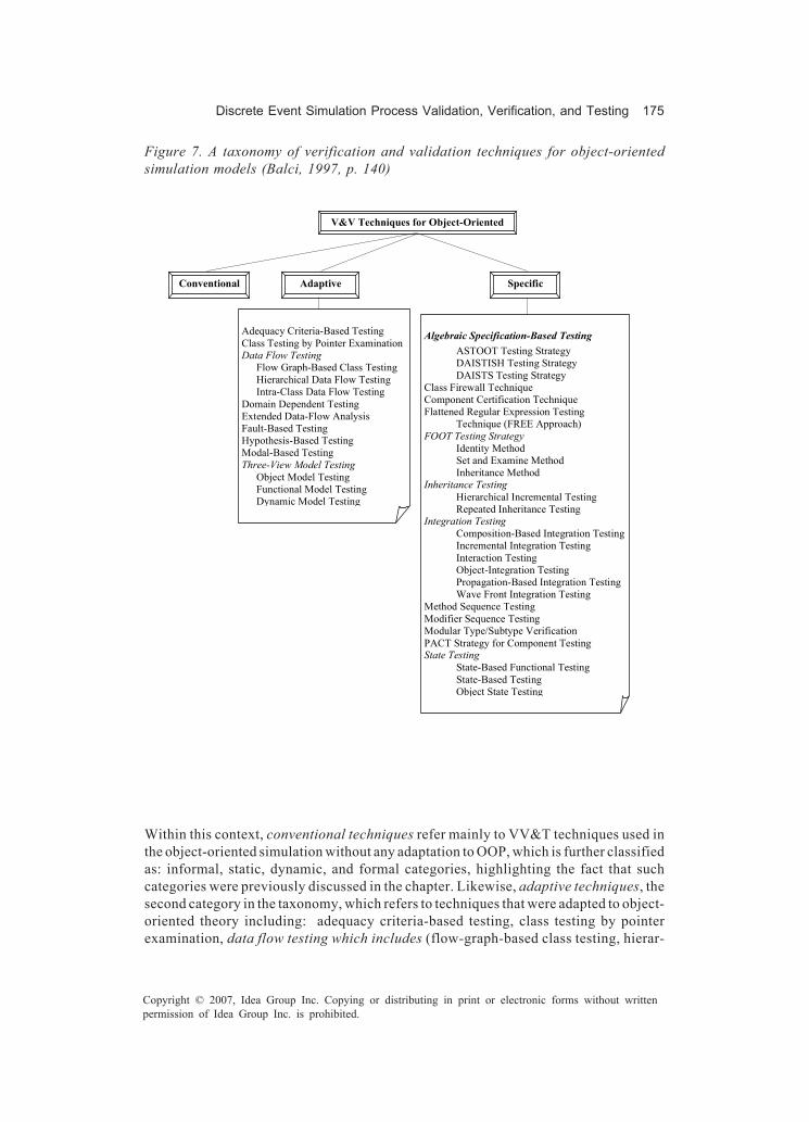
Discrete Event Simulation Process Validation, Verification, and Testing 175
Copyright © 2007, Idea Group Inc. Copying or distributing in print or electronic forms without writtenpermission of Idea Group Inc. is prohibited.
Within this context, conventional techniques refer mainly to VV&T techniques used inthe object-oriented simulation without any adaptation to OOP, which is further classifiedas: informal, static, dynamic, and formal categories, highlighting the fact that suchcategories were previously discussed in the chapter. Likewise, adaptive techniques, thesecond category in the taxonomy, which refers to techniques that were adapted to object-oriented theory including: adequacy criteria-based testing, class testing by pointerexamination, data flow testing which includes (flow-graph-based class testing, hierar-
Figure 7. A taxonomy of verification and validation techniques for object-orientedsimulation models (Balci, 1997, p. 140)
V&V Techniques for Object-Oriented Simulation Models
Conventional
Adequacy Criteria-Based Testing Class Testing by Pointer Examination Data Flow Testing
Flow Graph-Based Class Testing Hierarchical Data Flow Testing Intra-Class Data Flow Testing
Domain Dependent Testing Extended Data-Flow Analysis Fault-Based Testing Hypothesis-Based Testing Modal-Based Testing Three-View Model Testing
Object Model Testing Functional Model Testing Dynamic Model Testing
Algebraic Specification-Based Testing ASTOOT Testing Strategy DAISTISH Testing Strategy DAISTS Testing Strategy
Class Firewall Technique Component Certification Technique Flattened Regular Expression Testing
Technique (FREE Approach) FOOT Testing Strategy
Identity Method Set and Examine Method Inheritance Method
Inheritance Testing Hierarchical Incremental Testing Repeated Inheritance Testing
Integration Testing Composition-Based Integration Testing Incremental Integration Testing Interaction Testing Object-Integration Testing Propagation-Based Integration Testing Wave Front Integration Testing
Method Sequence Testing Modifier Sequence Testing Modular Type/Subtype Verification PACT Strategy for Component Testing State Testing
State-Based Functional Testing State-Based Testing Object State Testing
Specific
Adaptive

176 Abu-Taieh & El Sheikh
Copyright © 2007, Idea Group Inc. Copying or distributing in print or electronic forms without writtenpermission of Idea Group Inc. is prohibited.
chical data-flow testing, intraclass data-flow testing), domain-dependent testing, ex-tended data-flow analysis, fault-based testing, hypothesis-based testing, model-basedtesting, and three-view model testing, which includes object-model testing, functional-model testing, and dynamic-model testing.Finally, specific techniques, the third category in the taxonomy, are newly created basedon object-oriented formalism and used for object-oriented software. It should be takeninto consideration that those techniques are algebraic specification-based testing,ASTOOT testing strategy, DAISTISH testing strategy, DAISTS testing strategy, classfirewall technique, component certification technique, flattened regular expressiontesting, technique (FREE approach), FOOT testing strategy, identity method, set andexamine method, inheritance method, inheritance testing, hierarchical incremental test-ing, repeated inheritance testing, integration testing, composition-based integrationtesting, incremental integration testing, interaction testing, object-integration testing,propagation-based integration testing, wave front integration testing, method sequencetesting, modifier sequence testing, modular type/subtype verification, PACT strategyfor component testing, state testing, state-based functional testing, state-based testing,object state testing, and graph-based class testing.Within this context, Balci (1997) has classified DAISTS as a specific technique from thealgebraic specification-based testing. Furthermore, Gannon McMullin, and Hamlet(1981) has stated that data-abstraction implementation, specification, and testingsystem (DAISTS) “permits a program implementing an abstract data type to be augmentedwith specification axioms and test cases to explore the consistency of axioms andimplementation” (p. 212).In the same token, Balci (1997) has classified ASTOOT as a specific technique from thealgebraic specification-based testing . Furthermore, Doong and Frankl (1994) has statedthat a set of tools for object-oriented testing (ASTOOT) “includes an interactivespecification-based test-case-generation tool and a tool that automatically generatestest drivers. For any class C, ASTOOT can automatically generate a test driver, whichin turn automatically executes test cases and checks their results. Additionally, when analgebraic specification for C is available, ASTOOT can partially automate test generation.Thus the system allows for substantial automation of the entire testing process” (p. 102).Likewise, Balci (1997) has classified Daistish as a specific technique from the algebraicspecification-based testing . Hughes and Stotts (1996) have distinguishably describedDaistish as follows:
Daistish is a tool that performs systematic algebraic testing similar to Gannon’sDAISTS tool. However, Daistish creates effective test drivers for programs in languagesthat use side effects to implement ADTs; this includes C++ and most other object-oriented languages. The functional approach of DAISTS does not apply directly inthese cases. (p. 1)
It is worth mentioning, however, that Hughes and Stotts (1996) have compared Daistishto ASTOOT as follows:

Discrete Event Simulation Process Validation, Verification, and Testing 177
Copyright © 2007, Idea Group Inc. Copying or distributing in print or electronic forms without writtenpermission of Idea Group Inc. is prohibited.
Daistish differs from ASTOOT by using Guttag-style algebraic specs (functionalnotation), by allowing aliasing of type names to tailor the application of parametersin test cases, and by retaining the abilities of DAISTS to compose new test points fromexisting ones. Daistish is a Perl script, and is compact and practical to apply. (p. 1)
Additionally, the class firewall, denoted CFW(X) for a class X, is the set of classesgrouped within specific techniques that could be affected by changes to class X andthus, that should be retested when class X is changed (Labiche, Thévenod, Fosse,Waeselynck, & Durand 2000)Furthermore, model-based testing relies on execution traces of behavior models, mostimportantly since they are used as test cases for an implementation: input and expectedoutput. This complements the ideas of model-driven testing (Pretschner, 2005).In addition, Balci (1997) has categorized hierarchical incremental class testing as aspecific inheritance test, Harrold, McGregor, and Fitzpatrich (1992) has explained theprocess of a hierarchical incremental class test as follows:
1. First, a base class is tested by testing each member function individually and thentesting the interactions among the member functions.
2. The test suite, execution information, and association between the member func-tions and test cases is saved in a testing history.
3. Then, when a subclass is defined, the testing history of its parent, the definitionof the modifier and the inheritance mapping of the implementation language areused to derive the testing history for the subclass.
4. The subclass’s testing history indicates which attributes to (re)test in the subclassand which of the parent’s test cases can be reused.
Moreover, specification fault-based testing is one of the adaptive VV&T techniques, asRichardson, O’Malley, and Tittle (1989) have stated “The goal of spec/fault-basedtesting is to detect faults in the specification by revealing specification failures or todetect coding faults that are due to misunderstanding the specification by revealingimplementation failures” (p. 89). Based on Richardson‘s description, formal specificationlanguage is needed to use such technique.Binder (1995) has identified that FREE (flattened regular expression) is a state-basedtesting technique, as Balci (1997) has classified FREE as a specific VV&T technique,furthermore, Binder has stated FREE “technique can detect four kinds of bugs: missingtransition, incorrect transition, incorrect output actions, and incorrect states.” (Xu, Xu,& Nygard, 2005). As Xu et al. explain, FREE uses the generation of a transition tree froma state model, then, transition test sequences are transcribed from the tree, thus, FREEshows that the specifications are satisfied.Furthermore, Unified Modeling Language (UML) has been used in building simulationsystems by many, such as: Carr and Balci (2000), Lendermann, Gan, and McGinnis (2001),Ramakrishnan, Lee, and Wysk (2002), and even IBM (2005) advertises such an idea.
178 Abu-Taieh & El Sheikh
Copyright © 2007, Idea Group Inc. Copying or distributing in print or electronic forms without writtenpermission of Idea Group Inc. is prohibited.
Moreover, Linzhang et al. (2004) has stated that: “As a semi-formal modeling language,UML is widely used to describe analysis and design specifications by both academia andindustry, thus UML models become the sources of test generation naturally”, highlight-ing the fact that UML’s advantage in this case “is that they provide a convenient basisfor selecting tests” (Offutt & Abdurazik, 1999).
Mapping Software-EngineeringBest Practices to the Discrete
Event Simulation Process
Withers (2000) has described 13 software-engineering practices to be applied to simu-lation project, next an elaborate overview of the suggested best practices, noting thattwo of which have been compiled from Withers:
1. Formal risk management: utilized for modeling risks, which includes access tohistorical data, documenting existing and planned processes, and the ability tocomprehend the lack of management understanding of the modeling process andrequired sophisticated statistical analyses (Balci & Sargent, 1981; Withers, 2000).
2. Estimate cost and schedule empirically: takes place during the project planning,as some “measure of project complexity should be used as a basis” (Withers, 2000,p. 435).
3. Metric-based scheduling and management and tracking earned value: reflectedin short activities rather than long ones.
4. Defect tracking: reflected in tracking defects during the project.5. Treating human resources as the most important asset: such a recommendation
is applicable to any project.6. Configuration management: reflected in keeping a log of versions and dates of the
simulation system.7. Manage and trace requirements: explaining how the project manager would be
capable of keeping check on the project progress.8. System-based software design: indicates the involvement of programmers and
software engineers in the design.9. Design twice and code once: which really reflects the need to refrain from coding
and give an adequate time to design.10. Formal inspections: Withers (2000) states that this “should be conducted on least
the requirements, the project plan, the conceptual model, the model, and thetest plans” (p. 437).
11. Manage testing as a continuous process: testing like in Balci (1994, 1997) must bemanaged for the duration of the project.

Discrete Event Simulation Process Validation, Verification, and Testing 179
Copyright © 2007, Idea Group Inc. Copying or distributing in print or electronic forms without writtenpermission of Idea Group Inc. is prohibited.
12. Compile and smoke test frequently: Withers (2000) suggests that “Whenever anadditional capability is added to the model, a regression test of the prior capabilitiesshould be done first (p. 437).
Independence of VV&T
Many advocate the independence of VV&T pertaining to simulation, particularly sinceindependence provides an objective assessment platform, adds a new analytical per-spective, brings its own set of tools and techniques, introduces intermediate users, andsignificantly enhances testing as well as discovers design flaws and coding errors(Arthur & Nance, 2000). VV&T clearly crystallizes this need when the system is real-timecritical software, the program has a high cost of failure, or the cost of error detection,maintenance, or modification exceeds the cost of VV&T. This highlights the fact that withindependence we mean: technical, managerial, and financial independence (Arthur &Nance).
Future Trends
Indeed testing is a tedious, mind-numbing, lackluster, repetitive, and long process. Justlike compilers started years ago to locate syntax errors, VV&T tools are becoming wellknown. In fact, as seen in Table 2, there are many tools that test software. Whether the
Product Web site Use For
Programming Language
Latest Release
Date
vectorCAST www.vectorcast.com for c/c++, Delphi, java, Visual Basic, visual c++
—
testcomplete 3 www.automatedqa.com for win32, java, .NET —
The Grinder http://sourceforge.net/projects/grinder Java load-testing 5/25/ 2005
Mantis http://www.mantisbt.org/ Php, MySQL, Web-based bug tracking 5/25/ 2005
OpenSTA http://opensta.org/download.html Scripted HTTP and HHTPS load test 5/16/ 2005
TestMaker http://www.pushtotest.com/ solves bugs in the HTTP protocol handler
5/11/ 2005
ProofPower http://www.lemma-one.com/ProofPower/index/
supporting specification and proof in higher order logic (HOL) and in the Z notation
—
Table 2. VV&T software tools

180 Abu-Taieh & El Sheikh
Copyright © 2007, Idea Group Inc. Copying or distributing in print or electronic forms without writtenpermission of Idea Group Inc. is prohibited.
VV&T technique is static or dynamic, formal or informal, many tools have been developedto do the grubby work for the developer. Some tools, like ProofPower, go as far as offeringsupporting proof in higher order logic (HOL) and in the Z notation. As such, thosementioned hereinafter will be part of our life in validation, verification, accreditation, andsurly independence.
Conclusion
In conclusion, this chapter gave a full-fledged overview regarding the simulation ofVV&T techniques, whether they may be procedural or object-oriented simulations,putting forth various taxonomies for both types of VV&T techniques. Furthermore, thechapter highlighted the fact that the use of UML in simulation can be tuned to serve thepurpose of simplifying the VV&T process.In addition, mapping best practices of software engineering to simulation process,thirteen best practices recommended to be integrated within the simulation systemdevelopment.Finally, the chapter pinpointed the significance of the independence of VV&T, identify-ing the reasons behind advocating for it, the most important of which would be capabilityto provide an objective assessment platform.
References
Arthur, J., & Nance, R. (2000, December 10-13). Verification and validation withoutindependence: A recipe for failure. In J. A. Joines, R. R. Barton, K. Kang, & P. A.Fishwick (Eds.), Proceedings of the Winter Simulation Conference (pp. 859-856).San Diego, CA: Society for Computer Simulation International.
Balci, O. (1994). Validation, verification, and testing techniques throughout the life cycleof a simulation study. Annals of Operations Research, 53, 215-220.
Balci, O. (1995). Principles and techniques of simulation validation, verification, andtesting. In C. Alexopoulos, K. Kang, W. R. Lilegdon, & D. Goldsman (Eds.),Proceedings of the 1995 Winter Simulation Conference (pp. 147-154). New York:ACM Press.
Balci, O. (1997, December 7-10). Verification, validation and accreditation of simulationmodels. In S. Andradóttir, K. J. Healy, D. H. Withers, & B. L. Nelson (Eds.),Proceedings of the Winter Simulation Conference, Atlanta, GA ( pp. 135-141).Retrieved April 2003, from http://www.informs-sim.org/wscpapers.html
Balci, O. (2003). Verification, validation, and certification of modeling and simulationapplications. ACM Transactions on Modeling and Computer Simulation, 11(4),352-377.

Discrete Event Simulation Process Validation, Verification, and Testing 181
Copyright © 2007, Idea Group Inc. Copying or distributing in print or electronic forms without writtenpermission of Idea Group Inc. is prohibited.
Balci, O., Glasow, P. A., Muessig, P., Page, E. H., Sikora, J., Solick, S., & Youngblood, S.(1996, November). Department of defense verification, validation and accredita-tion (VV&A) recommended practices guide. Alexandria, VA: Defense Modelingand Simulation Office. Retrieved May 25, 2005, from http://vva.dmso.mil/Mini_Elabs/VVtech-dynamic.htm
Balci, O., Nance, R., Arthur, J., & Ormsby, W. (2002, December 8-11). Expanding ourhorizons in verification, validation, and accreditation research and practice. In E.Yücesan, C. H. Chen, J. L. Snowdon, & J. M. Charnes (Eds.), Proceedings of the2002 Winter Simulation Conference (pp. 653-663). Piscataway, NJ: IEEE.
Balci, O., & Sargent, R. G. (1981, April). A methodology for cost-risk analysis in thestatistical validation of simulation models. Communications of the ACM, 24(11),190-197.
Banks, J. (1999, December 5-8). Introduction to simulation. In P. A. Farrington, H. B.Nembhard, D. T. Sturrock, & G. W. Evans (Eds.), Proceedings of the 1999 WinterSimulation Conference (pp. 7-13). New York: ACM Press.
Banks, J., Carson, J., Nelson, B., & Nicol, D. (2001). Discrete-event system simulation (3rd
ed.). Upper Saddle River, NJ: Prentice Hall International Series.Baradhi, G., & Mansour, N. (1997, September 29-October 2). A comparative study of five
regression testing algorithms. In Proceedings of the Software Engineering Con-ference, Australia (pp. 174-182).
Binder, R. V. (1995). State-based testing. Object Magazine, 5, 75-78.Carr, J., & Balci, O. (2000, December 10-13). Verification and validation of object-oriented
artifacts throughout the simulation model development life cycle. In A. Joines, R.R. Barton, K. Kang, & P. A. Fishwick (Eds.), Proceedings of the Winter SimulationConference (pp. 866-871). Piscataway, NJ: IEEE.
Doong, R., & Frankl, P. (1994). The ASTOOT approach to testing object-orientedprograms. ACM Trans. on Software Engineering and Methodology, 3(2), 101-130.
Freedman, D. P., & Weinberg, G. M. (2000). Handbook of walkthroughs, inspections,and technical reviews: Evaluating programs, projects, and products (3rd ed.). NewYork: Dorset House Publishing Co.
Gannon J., McMullin, P., & Hamlet, R. (1981, July). Data-abstraction implementation,specification, and testing. ACM Transactions on Programming Languages andSystems, 3(3), 211-223.
Harrold, M., McGregor, J., & Fitzpatrich, K. (1992). Incremental testing of object-orientedclass structures. In Proceedings of the 14th International Conference on SoftwareEngineering, Melbourne, Australia (pp. 68-80). Retrieved April 2004, from http://citeseer.ist.psu.edu/harrold92incremental. html
Hoffer, J. A., George, J. F., & Valacich, J. S. (2005). Modern systems analysis and design(4th ed). Upper Saddle River, NJ: Prentice Hall.
Hughes, M., & Stotts, D. (1996). Daistish: Systematic algebraic testing for OO programsin the presence of side-effects. In Proceedings of the ACM SIGSOFT Int. Symp. OnSoftware Testing and Analysis (pp. 53-61). Retrieved June 12, 2005, from http://rockfish.cs.unc.edu/pubs/issta96.pdf
182 Abu-Taieh & El Sheikh
Copyright © 2007, Idea Group Inc. Copying or distributing in print or electronic forms without writtenpermission of Idea Group Inc. is prohibited.
IBM. (n.d.). Retrieved June 12, 2005, from http://www-106.ibm.com/developerworks/rational/library/2797.html
Joines, J., & Roberts, S. (1998, December 13-16). Fundamentals of object-orientedsimulation. In D. J. Medeiros, E. F. Watson, J. S. Carson, & M. S. Manivannan(Eds.), Proceedings of the 1998 Winter Simulation Conference (pp. 141-149). LosAlamitos, CA: IEEE Computer Society Press.
Kleignen, J., Bettonvil, B., & Gmenendahl, W. (1996). Validation of trace-driven simula-tion models: Regression analysis revisited. In J. M. Ckrnes, D. J. Morrice, D. T.Brunner, & J. J. Swain (Eds.), Proceedings of the Winter Simulation Conference(pp. 352-359). New York: ACM Press.
Labiche, Y., Thévenod, P., Fosse, H., Waeselynck, M., & Durand, H. (2000). Testinglevels for object-oriented software. Proceedings of the 22nd International Confer-ence on Software Engineering, Limerick, Ireland (pp. 136-145). New York: ACMPress.
Leemis, L. (2003 December 7-10). Input modeling. In S. Chick, P. J. Sánchez, D. Ferrin, &D. J. Morrice (Eds.), Proceedings of the 2003 Winter Simulation Conference, NewOrleans, LA (pp. 14-24). Retrieved April 2003, from http://www.informs-sim.org/wscpapers.html
Lendermann, P., Gan, B., & McGinnis, L. (2001, December 9-12). Distributed simulationwith incorporated aps procedures for high-fidelity supply chain optimization. In B.A. Peters, J. S. Smith, D. J. Medeiros, & M. W. Rohrer (Eds.), Proceedings of theWinter Simulation Conference, Arlington, VA (pp. 805-812). Retrieved April 2003,from http://www.informs-sim.org/wscpapers.html
Linzhang, W., Jiesong, Y., Xiaofeng, Y., Jun, H., Xuandong, L., & Guoliang, Z. (2004).Generating test cases from UML activity diagram based on gray-box method.Apsec, 284-291.
Mansour, N., & Brardhi, B. R. (2001). Empirical comparison of regression test selectionalgorithm. The Journal of System and Software, 57, 79-90.
Manta. (n.d.). Retrieved June 12, 2005, from http://manta.cs.vt.edu/cs6204Offutt, J., & Abdurazik, A. (1999, October). Generating tests from UML specifications.
In Second International Conference on the Unified Modeling Language (UML99),Fort Collins, CO.
Orso, A., Shi, N., & Harrold, M. J. (2004, October 31-November 6). Scaling regressiontesting to large software systems. SIGSOFT’04/FSE-12, Newport Beach, CA (pp.241-251).
Page, H., & Nance, R. (1997, July). Parallel discrete event simulation: A modelingmethodological perspective. ACM Transactions on Modeling and ComputerSimulation, 7(3), 88-93.
Paul, R. J., & Balmer D.W. (1998). Simulation modelling. Lund, Sweden: Chartwell-BrattStudent Text Series.
Pezz, M., & Young, M. (2004). Testing object oriented software. In Proceedings of the26th International Conference on Software Engineering (ICSE’04).
Discrete Event Simulation Process Validation, Verification, and Testing 183
Copyright © 2007, Idea Group Inc. Copying or distributing in print or electronic forms without writtenpermission of Idea Group Inc. is prohibited.
Pidd, M. (1998). Computer simulation in management science (4th ed.). Chichester, UK:John Wiley & Sons.
Pressman, R. (2005). Software engineering: A practitioner’s approach (6th ed.). NewYork: McGraw Hill.
Pretschner, A. (2005, May 15-21). Model based testing. In Proceedings of ICSE’05(pp.722-723). St. Louis, MO: ACM.
Ramakrishnan, S., Lee, S., & Wysk, R. (2002, December 8-11). Implementation of asimulation-based control architecture for supply chain interactions. In E. Yücesan,C. H. Chen, J. L. Snowdon, & J. M. Charnes (Eds.), Proceedings of the WinterSimulation Conference, San Diego, CA. Retrieved April 2003, from http://www.informs-sim.org/wscpapers.html
Richardson, D. J., O’Malley, O., & Tittle, C. (1989, December). Approaches to specifica-tion-based testing. In Proceedings of ACM SIGSOFT Symposium on SoftwareTesting, Analysis and Verification (pp. 86-96). New York: ACM Press.
Robinson S. (1999, December 10-13). Three sources of simulation inaccuracy (and howto overcome them). In P. A. Farrington, H. B. Nembhard, D. T. Sturrock, & G. W.Evans (Eds.), Proceedings of the 1999 Winter Simulation Conference, Orlando,FL (pp. 1701-1708).
Sadowsk, R. P. (1991). Avoiding the problems and pitfalls in simulation. Winter Simula-tion Conference Proceedings of the 23rd Conference on Winter simulation (pp.48-55), Phoenix, AZ. Washington, DC: IEEE Computer Society.
Sargent, R. (1998, December 13-16). Verification and validation of simulation models. InD. J. Medeiros, E. F. Watson, J. S. Carson, & M. S. Manivannan (Eds.), Proceedingsof the Winter Simulation Conference, Washington, DC (pp. 121-130). RetrievedApril 2003, from http://www.informs-sim.org/wscpapers.html
Sargent, R. (1999, December 10-13). Validation and verification of simulation models. InP. A. Farrington, H. B. Nembhard, D. T. Sturrock, & G. W. Evans (Eds.), Proceedingsof the Winter Simulation Conference, Orlando, FL (pp. 39-48).
Sargent, R. (2003, December 7-10). Verification and validation of simulation models. InS. Chick, P. J. Sánchez, D. Ferrin, & D. J. Morrice (Eds). Proceedings of the WinterSimulation Conference, New Orleans, LA (pp. 39-48). Retrieved April 2003, fromhttp://www.informs-sim.org/wscpapers.html
Sebesta, R. W. (2003). Concepts of programming languages (6th ed.). Addison-Wesley.Shannon, R. (1998, December 13-16). Introduction to the art and science of simulation.
In D. J. Medeiros, E. F. Watson, J. S. Carson, & M. S. Manivannan. Proceedingsof the Winter Simulation Conference, Washington, DC (pp. 7-14). Retrieved April2003, from http://www.informs-sim.org/wscpapers.html
Smith, R. (1998, December 13-16). Essential techniques for military modeling & simula-tion. In D. J. Medeiros, E. F. Watson, J. S. Carson, & M. S. Manivannan. Proceed-ings of the Winter Simulation Conference, Washington, DC (pp. 805-812). Re-trieved April 2003, from http://www.informs-sim.org/wscpapers.html

184 Abu-Taieh & El Sheikh
Copyright © 2007, Idea Group Inc. Copying or distributing in print or electronic forms without writtenpermission of Idea Group Inc. is prohibited.
Sommerville, I. (n.d.). Software engineering (6th ed.). Upper Saddle River, NJ: Addison-Wesley, Pearson Education.
Wikipedia. (n.d.). Retrieved June 12, 2005, from http://en.wikipedia.org/wiki/Lambda_calculus
Withers, D. (2000, December 10-13). Software engineering best practices applied to themodeling process. In J. A. Joines, R. R. Barton, K. Kang, & P. A. Fishwick (Eds.),Proceedings of the Winter Simulation Conference, Orlando, FL (pp. 432-439).Retrieved April 2003, from http://www.informs-sim.org/wscpapers.html
Xu, D., Xu, W., & Nygard K. (2005, July 14-16). A state-based approach to testing aspect-oriented programs. In Proceedings of the 17th International Conference onSoftware Engineering and Knowledge Engineering (SEKE’05), Taiwan. Re-trieved April 2004, from http://cs.ndsu.edu/~dxu/publications/SEKE05-xu.pdf
Yilmaz, L. (2001). Automated object-flow testing of dynamic process interaction models.In B. A. Peters, J. S. Smith, D. J. Medeiros, & M. W. Rohrer (Eds.), Proceedings ofthe Winter Simulation Conference (pp. 586-594). Retrieved April 2003, from http://www.informs-sim.org/wscpapers.html
Zammit, J. (2005). Correct cystem, Web site for information systems engineering.University of Malta. Retrieved June, 18, 2005, from http://www.cis.um.edu.mt/~jzam/vv.html

The STECC Framework 185
Copyright © 2007, Idea Group Inc. Copying or distributing in print or electronic forms without writtenpermission of Idea Group Inc. is prohibited.
Chapter IX
The STECCFramework:
An Architecture forSelf-Testable Components
Sami Beydeda, Federal Finance Office, Germany
Abstract
Development of a software system from existing components can surely have variousbenefits, but can also entail a series of problems. One type of problem is caused by alimited exchange of information between the developer and user of a component. Alimited exchange and thereby a lack of information can have various consequences,among them the requirement to test a component prior to its integration into a softwaresystem. A lack of information cannot only make testing prior to integration necessary;it can also complicate this task. However, difficulties in testing can be avoided if certainprovisions to increase testability are taken beforehand. This article briey describes anew form of improving testability of, particularly commercial, components, the self-testing COTS components (STECC) strategy and explains in detail the STECCframework, which implements the necessary technical architecture to augment Javacomponents with self-testability.

186 Beydeda
Copyright © 2007, Idea Group Inc. Copying or distributing in print or electronic forms without writtenpermission of Idea Group Inc. is prohibited.
Introduction
A major trend in software engineering is that of component-based development. Theunderlying idea of component-based development is to use existing components for theconstruction of a software system and to construct it by integrating them instead ofprogramming the software system from scratch. This idea is neither new in the construc-tion of complex systems in general nor in software engineering in particular. In other, moremature engineering disciplines, such as the construction of electronic devices, it is ausual procedure to use existing components. In software engineering, the use ofcomponents in software development was suggested more than 30 years ago (McIlroy,1968).The expected benefits of using components in software development and the motiva-tions for component-based development are manifold. Among others, components areexpected to improve the success factors of software-development projects, such asquality of the system developed and adherence to time and budget restrictions, similarto development projects in other disciplines. However, software components stronglydiffer from components such as those used in the construction of electronic devices.Software components generally have much more inherent complexity. Appropriatemethods to cope with this complexity still do not exist, which gives an indication of thematurity of this paradigm and of software engineering as a whole. Even if some successis achieved with the use of components, component-based development still has to showits full potential.As one of the success factors, the use of components was assumed to have positivelyaffected the quality of the software system developed. Components were assumed tohave reached a high level of quality in a short period of time, for instance, due to marketpressure. Also, software systems consisting of such components were expected toinherit this high level of quality. Unfortunately, experience showed that this assumptiondoes not necessarily hold in practice. One reason is a lack of information (Beydeda &Gruhn, 2003b; Beydeda & Gruhn, 2003c), particularly in the case of commercial compo-nents. The provider of a component might not be able to anticipate all possibleapplication contexts in which the component might be used. The same also applies totechnical environments in which the component might be embedded. Assumptions in thedevelopment of a component concerning, for instance, the application environmentmight be inaccurate or even wrong and quality assurance conducted by the componentprovider might not be effective. The component might exhibit failures.A lack of information can also concern the user of a component. The user might also sufferfrom such a lack insofar that the component might not be sufficiently documented dueto inaccurate or incorrect information from the provider with regards to the requireddocumentation. This obviously can have various adverse effects on development andmaintenance of a system using the component. Context-dependent tests by the compo-nent provider and insufficient documentation often obligate the component user to testa component prior to its use in the development of a software system. A problem, againdue to a lack of information, might be encountered when failures are revealed in suchtests. The component user usually has to rely on the component provider to remove thefaults causing the failures, which is one of the forms in which the component user’s

The STECC Framework 187
Copyright © 2007, Idea Group Inc. Copying or distributing in print or electronic forms without writtenpermission of Idea Group Inc. is prohibited.
development of a system might depend on the component provider’s maintenance of thecomponent. A lack of information might also cause other forms of dependence, introduc-ing risks in the development of a component-based system. Moreover, testing itselfmight also be affected by a lack of information. For instance, source code is seldomavailable to the user of a component due to various reasons. The user therefore cannot,for instance, conduct program-based testing, even if required in certain cases. A lack ofinformation thus not only necessitates quality assurance to be conducted by thecomponent user but also complicates it.This article briey introduces the self-testing COTS components (STECC) method andexplains in detail the STECC framework. The STECC method aims to meet the require-ments of both the provider and user of a component. On the one hand, the provider ofa component usually does not wish to disclose certain information. On the other hand,the user needs to test the component that may require this information. The STECCmethod does not only benefit the user of a component in that the user can test acomponent as required; it can also benefit its provider, as self-testability provided by anappropriately augmented component can be an advantage in competition.The underlying idea of this method is to augment a component with the capabilities oftesting tools to support testing tasks carried out by the component user. The STECCmethod obviates access to certain information by the user, since tasks for which the usermight require this information are conducted by a STECC self-testable component itself.This information is not disclosed to the user at all; it is processed by the component inan encapsulated form. Specifically, a STECC self-testable component is capable ofgenerating test cases for program-based testing. Source code as the main input for thiskind of testing thereby does not need to be disclosed to the tester.A component might be used in development of various types of systems with distinctquality requirements. A STECC seft-testable component takes this into account insofarthat it does not assume a specific adequacy criterion for its testing, but allows its usersto specify arbitrary control ow criteria. This exibility is achieved by the binary search-based test case generation (BINTEST) algorithm (Beydeda and Gruhn, 2003a; Beydedaand Gruhn, 2003d), which, together with certain analysis algorithms, constitutes the coreof the STECC method. This exibility requires certain provisions, among them the needto augment the component accordingly by integrating it with the STECC framework. TheSTECC framework mainly implements the BINTEST algorithm as well as the analysisalgorithms required by it.
Basic Terms
Components
In recent years, components and component-based development received much atten-tion, certainly due to the explicit support for software reuse and the abstraction principle,two methods of software development. A large number of scientific articles are published

188 Beydeda
Copyright © 2007, Idea Group Inc. Copying or distributing in print or electronic forms without writtenpermission of Idea Group Inc. is prohibited.
on the subjects of components and component-based development and companies havereleased several component models, allowing the development of component-basedsystems. The subjects of components and component-based development, however, arestill not mature, as definitions of basic terms, such as that of a component, did notconverge. The various definitions are not discussed here. According to Szyperski (1998),one can assume that:
• Definition 1: A software component is a unit of composition with contractuallyspecified interfaces and explicit context dependences only. A software componentcan be deployed independently and is subject to composition by third parties.
A similarity between component-based and object-oriented development is the distinc-tion between components and classes, respectively, and their instances. A componentis a static description of its instances, while a class is a static description of correspond-ing objects. The output and behavior of an instance generally depend on two factors,namely its input and its state. Instances, however, are sometimes assumed to be stateless,such as in Szyperski (1998), who shows various consequences. One of the importantconsequences is that instances of a component do not differ with respect to their outputand behavior, which solely depend on the input. A component-based system thus needsto maintain a single instance of a component. However, this does not mean that it cannotbe multithreaded. In practice, however, instances are often implemented statefully, andthe instances of a component are distinguished from each other with regard to their state.In some applications, it might be necessary to make an instance persistent, for example,by storing its state in a database. Such an instance exists beyond the termination of thecreation process and can be identified by its state.
Figure 1. Metamodel of basic terms

The STECC Framework 189
Copyright © 2007, Idea Group Inc. Copying or distributing in print or electronic forms without writtenpermission of Idea Group Inc. is prohibited.
The type of a component is often defined in terms of the interface implemented by it. Thecomponent type names all operations of the corresponding interface, the number andtypes of parameters, and the types of values returned by each operation (Szyperski,1998). Just as a component can implement several interfaces, it can also be of severaltypes. The operations of a component are accessed through its interfaces and areimplemented by its methods. Figure 1 shows a metamodel of the basic terms (Gruhn &Thiel, 2000). Note that the metamodel in Figure 1 also indicates that a component can beimplemented according to the object-oriented paradigm. This is, however, not anobligation (Szyperski).
Enterprise JavaBeans
One of the component models widely used in practice is the one following the EnterpriseJavaBeans specification released by Sun Microsystems. The Enterprise JavaBeansspecification defines the Enterprise JavaBeans architecture for the development ofdistributed, component-based client-server systems. The initial specification of Enter-prise JavaBeans was released in 1998. Since then, the specification was developedfurther, and several extensions were added to the initial release. In the following, theEnterprise JavaBeans component model and framework are explained with respect torelease 2.1 of the specification, which can be found in DeMichiel (2002). Other examplesof component models are the CORBA component model proposed by the ObjectManagement Group (2002) and the component object model and related technologiesproposed by the Microsoft Corporation (1995).One of the component types defined by the Enterprise JavaBeans specification is thesession bean. The primary purpose of a session bean is to encapsulate business logic.A session bean is usually nonpersistent, that is, its data is not stored in a database andis lost after the session is terminated. Furthermore, multiple clients cannot access asession bean simultaneously. A session bean provides its services through specificinterfaces, depending on the type of client and service. Clients that can access a sessionbean can either be local or remote, and the provided services can be classified as eitherbeing related to the lifecycle of a particular session bean or the business logic imple-mented. In this context, the main distinction between a local and a remote client is thatlocal clients execute in the same Java virtual machine, and that the location of the sessionbean is not transparent for local clients, whereas a remote client can execute in a differentJava virtual machine and thus on a different host, so the location of the session bean istransparent.Figure 2 shows two session beans embedded in the component framework as specifiedby the Enterprise JavaBeans specification, which defines a component frameworkconsisting of servers and containers to support the component model. A server isgenerally responsible for providing technical services such as persistence, transactions,and security, whereas a container provides services related to management of thecomponent lifecycle. An enterprise bean is encapsulated in a container, which is in turnembedded in a server. The Enterprise JavaBeans specification, however, does not clearlyseparate containers from servers and both terms are often used interchangeably. Thecomponent framework consisting of a server and a container is transparent to the user
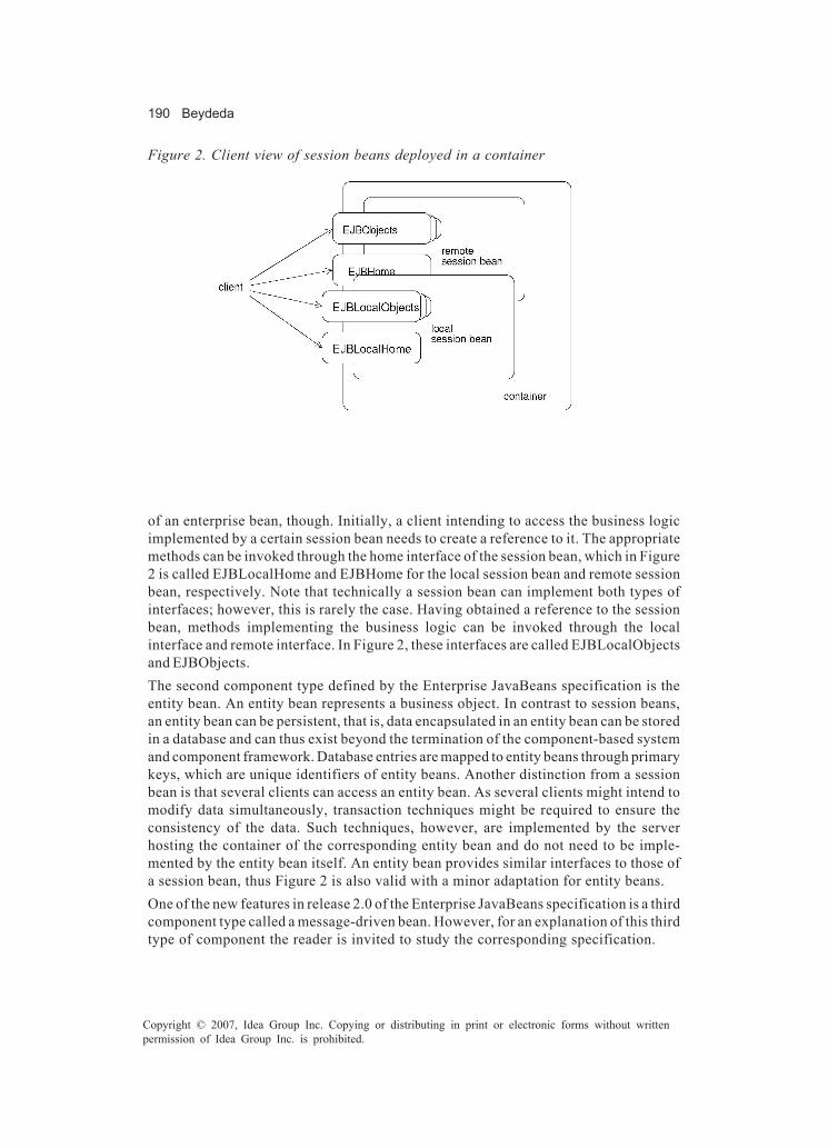
190 Beydeda
Copyright © 2007, Idea Group Inc. Copying or distributing in print or electronic forms without writtenpermission of Idea Group Inc. is prohibited.
of an enterprise bean, though. Initially, a client intending to access the business logicimplemented by a certain session bean needs to create a reference to it. The appropriatemethods can be invoked through the home interface of the session bean, which in Figure2 is called EJBLocalHome and EJBHome for the local session bean and remote sessionbean, respectively. Note that technically a session bean can implement both types ofinterfaces; however, this is rarely the case. Having obtained a reference to the sessionbean, methods implementing the business logic can be invoked through the localinterface and remote interface. In Figure 2, these interfaces are called EJBLocalObjectsand EJBObjects.The second component type defined by the Enterprise JavaBeans specification is theentity bean. An entity bean represents a business object. In contrast to session beans,an entity bean can be persistent, that is, data encapsulated in an entity bean can be storedin a database and can thus exist beyond the termination of the component-based systemand component framework. Database entries are mapped to entity beans through primarykeys, which are unique identifiers of entity beans. Another distinction from a sessionbean is that several clients can access an entity bean. As several clients might intend tomodify data simultaneously, transaction techniques might be required to ensure theconsistency of the data. Such techniques, however, are implemented by the serverhosting the container of the corresponding entity bean and do not need to be imple-mented by the entity bean itself. An entity bean provides similar interfaces to those ofa session bean, thus Figure 2 is also valid with a minor adaptation for entity beans.One of the new features in release 2.0 of the Enterprise JavaBeans specification is a thirdcomponent type called a message-driven bean. However, for an explanation of this thirdtype of component the reader is invited to study the corresponding specification.
Figure 2. Client view of session beans deployed in a container

The STECC Framework 191
Copyright © 2007, Idea Group Inc. Copying or distributing in print or electronic forms without writtenpermission of Idea Group Inc. is prohibited.
Commercial-Off-the-Shelf (COTS) Components
In comparison to other reusable software entities, one of the distinguishing features ofcomponents, particularly those referred to as commercial-off-the-shelf (COTS) compo-nents, are their market-related aspects. According to Basili and Boehm (2001), a COTScomponent has the following characteristics:
• The buyer has no access to the source code.• The vendor controls its development.• It has a nontrivial installed base.
The term COTS component is, however, not uniquely defined, as a discussion of thevarious definitions in Morisio and Torchiano (2002) shows, and the above characteristicsdo not exist to the same degree for each commercially available component. Among otherfactors, the existence of the above characteristics depends on the organizational relationbetween the vendor of the component and its buyer. The organizational relationsbetween the component provider and component user can be manifold, and a componentcan be associated with one of following categories (Carney & Long, 2000):
• Independent commercial item: A component can be an independent commercialitem that can be purchased from a possibly anonymous component market. Thiscategory of components is referred to as COTS components in the following.
• Special version of commercial item: A component can also be a special versionof a commercial component. The component user might contract with the compo-nent provider to produce a customized version of a commercially available compo-nent.
• Component produced by contract: Depending on the organizational relation, acomponent can also be produced by contract. The component user can ask thecomponent provider to develop a component for an agreed upon fee.
• Existing component from external sources: A component can originate from anexternal source without being commercial. The component provider and compo-nent user might reside in different organizations, but the component could be onedeveloped under a joint contract.
• Component produced in-house: Finally, a component can also be developed for aspecific project. The component provider and component user might be involvedin the same project or the same person can even play the roles of the componentprovider and component user.
This chapter focuses on COTS components. If not otherwise noted, components areassumed to have the above characteristics of COTS components, and the two termscomponent and COTS component are used interchangeably. Regarding the organiza-

192 Beydeda
Copyright © 2007, Idea Group Inc. Copying or distributing in print or electronic forms without writtenpermission of Idea Group Inc. is prohibited.
tional relation between the provider and user of a component, components are assumedto be independent commercial items.
Overall Strategy of the STECC Method
Misperceptions in Quality Assurance of Components
It is often argued that the quality of components will improve under certain conditionsand less quality assurance actions will be required in the development of a component-based system to satisfy given quality requirements. The conditions under which thequality of components will improve according to this argumentation include (Szyperski,1998):
• Frequent reuse: Reuse is generally supposed to have a positive effect on thequality of the software entity reused. A frequently reused component is expectedto improve in quality, since frequent reuse is expected to reveal failures and otheradverse behaviors that possibly would not be revealed when, instead of beingreused, the component would be redeveloped and tested from scratch.
• Competitive markets: Competitive markets are also supposed to contribute toimprovements of component quality, since quality is expected to become a successfactor in such markets.
One of the implications of this argumentation described in the literature is that qualityassurance actions are considered less important in component-based development thanin software development in general. Components are supposed to possess a certaindegree of quality , which makes further quality assurance actions obsolete, and compo-nent-based systems are expected to inherit the quality of its single constituents.However, these arguments do not take into account the following:Firstly, the quality of an entity, in this context a component, is usually defined with regardto stated or implied needs. In this context, stated and implied needs refer to those of aparticular component user. The needs of one component user might contradict those ofanother user and might also change after some time. Thus, even if the quality of acomponent might be sufficient according to the needs of a particular component user,additional quality assurance action might nevertheless be necessary prior to use by thesame component user due to a change in requirements and by another component userdue to a difference the needs.Secondly, competitive markets also do not necessarily disburden the component userfrom conducting quality assurance actions. The needs of the component users might notbe entirely known to the component provider so that the step taken by the componentprovider in order to increase quality might not be successful. Such problems are

The STECC Framework 193
Copyright © 2007, Idea Group Inc. Copying or distributing in print or electronic forms without writtenpermission of Idea Group Inc. is prohibited.
particularly caused by a limited exchange of information between the componentprovider and component user.Limited exchange of information between the roles of the component provider andcomponent user does not only limit the positive effect of competitive markets oncomponent quality. It also concerns several other issues in developing components andcomponent-based systems and can even be considered as the main factor in distinguish-ing testing components from testing software in general.
Organization Relation as an Obstacle forInformation Exchange
Various factors impact the exchange of information between the component provider andcomponent user. The information requested by one role and delivered by the other candiffer in various aspects, if it is delivered at all. It can differ syntactically insofar that itis, for instance, delivered in the wrong representation, and it can also differ semanticallyin that it is, for instance, not on the required abstraction level. The differences might bedue to various factors, one of them being the organizational relation between the tworoles. With respect to the organizational relation, a component can be associated withone of the categories: independent commercial item, special version of commercial item,component produced by contract, existing component from external sources, andcomponent produced in-house. Information exchange between the component providerand component user depends, as one factor, on the category into which the componentfalls regarding the organizational relation between the two roles.At one end of the spectrum, the component can be a commercial item. In this case, thequality of information exchange between component provider and component user isoften the worst in comparison to the other cases. There are various reasons for this, suchas the fact that the component provider might not know the component user due to ananonymous market. In such a case, the component provider can base development of thecomponent on assumptions and deliver only information to the component user that issupposedly needed. Furthermore, several component users might use the component,and the component provider might decide to only consider the needs of the majority ofthem. The specific needs of a single component user might then be ignored. Finally, thecomponent provider might not disclose detailed technical information even if needed bythe component user to avoid another component provider receiving this information. Thecomponent provider might decide to only make information available that respectsintellectual property and retains competitive advantage.At the other end of the spectrum, the component can be produced in-house. The qualityof information exchange between component provider and component user then is oftenthe best in comparison to the other cases. One of the reasons for this can be the fact thatthe component is developed in the same project in which it is assembled. The exchangeof information in both directions, from the component provider to the component userand in the reverse direction, can take place without any incompatibility in the requestedand delivered information. Furthermore, the component provider and component user are
194 Beydeda
Copyright © 2007, Idea Group Inc. Copying or distributing in print or electronic forms without writtenpermission of Idea Group Inc. is prohibited.
roles, so the same person can even play them if the component is used in the same projectin which it is developed. Information would not even need to be exchanged in that case.
STECC Approach to Tackle a Lack of Information
A lack of information might require the testing of a component by its user prior to itsintegration into a system, and might significantly complicate this task at the same time.The component user might not possess the required information for this task. Theoreti-cally, the component user can test a component by making certain assumptions andapproximating the information required. Such assumptions, however, are often tooimprecise to be useful. For instance, control-dependence information can be approxi-mated in safety-critical application contexts by conservatively assuming that everycomponent raises an exception, which is obviously too imprecise and entails a highertesting effort than necessary (Harrold, 2000; Harrold, Liang, & Sinha, 1999).Even though source code is often claimed to be required for testing purposes, it is notactually required by itself for testing purposes. Rather, it often acts as the source of otherinformation, for example, with regards to control-dependence. Instead of making sourcecode available to allow the generation of such information, the required information canalso be delivered directly to the component user, obviating source code access. This typeof information is often referred to as metainformation (Orso, Harrold, & Rosenblum, 2000).Even though the required information might already be available from testing activities,the component provider might still not deliver this information to the component user.One reason may be that detailed and sensitive information, including parts of the sourcecode, may be deduced from it, depending on the granularity of the metainformation.Therefore, there is a natural boundary limiting the level of detail of the information thatcan be delivered to the user. For some application contexts, however, the level of detailmight be insufficient and the component user might not be able to test the componentaccording to certain quality requirements.The underlying strategy of the STECC method differs from those discussed so far.Instead of providing the component user with information required for testing, compo-nent user tests are explicitly supported by the component. The underlying strategy ofthe method is to augment a component with functionality specific to testing tools. Acomponent possessing such functionality is capable of testing its own methods byconducting some or all activities of the component user’s testing processes; it is thusself-testing. Self-testability does not obviate the generation of detailed technicalinformation. In fact, this information is generated by the component itself at runtime andis internally used in an encapsulated manner. The generated information is transparentto the component user and can thus be more detailed than in the above case. Conse-quently, tests carried out by the component user through the self-testing capability canbe more thorough than when using metainformation. Self-testability allows the compo-nent user to conduct tests and does not require the component provider to disclosesource code or other detailed technical information. It thereby meets the demands of bothparties. The overall objective of the STECC method is to provide the component providerand component user the necessary means to enhance a component with this capabilityand to use it for program-based testing.

The STECC Framework 195
Copyright © 2007, Idea Group Inc. Copying or distributing in print or electronic forms without writtenpermission of Idea Group Inc. is prohibited.
Support of Typical Testing Activities
The STECC method supports most of the typical testing activities conducted by thecomponent user, as shown by Table 1. In particular, typical testing activities are impactedas follows:
• Test-plan definition: Some decisions usually made during the definition of a testplan are addressed by STECC method conventions. Such decisions concern thetarget component model and framework. The STECC method technically requiresthat the component under consideration is a Java component. Furthermore, thedecisions taken beforehand also encompass the type of adequacy criteria thatmeasure testing progress. Test cases are generated and testing progress ismeasured with respect to a control-flow criterion, which can be chosen freely. Thecomponent user can specify the control-flow criterion according to the qualityrequirements of the application context.
• Test-case generation: The STECC method includes a test-case generation algo-rithm. Generation of test cases, particularly according to program-based adequacycriteria, is an integral constituent of self-testability as assumed by the STECCmethod. Test-case generation is one of the important tasks affected by a lack ofinformation, since a lack of source code strongly hinders generation of test casesby the component user. The task of test-case generation is conducted in the contextof the STECC method by the binary search-based test-case generation (BINTEST)algorithm and its auxiliary analysis algorithms.
• Test-driver and stub generation: The component user does not need to generatetest drivers for testing methods of a component. The STECC framework, whichtechnically supports the STECC method, provides the required test drivers. Stubs,however, might be necessary if the method to be tested needs to invoke methodsof absent components. A component can often be embedded in a wide variety ofapplication contexts, so the specific application context can often not be antici-pated. The component user either needs to provide the specific stubs or embed thecomponent in the target application context.
• Test execution: The execution of methods under consideration with generated testcases is also conducted by the STECC method. The BINTEST algorithm is a
Table 1. Typical activities in testing processes and their support by the STECC method
STECC method supported Component user’s responsibility Test-plan definition + + Test-case generation + - Test-driver and stub generation +/- + Test execution + - Test evaluation - +

196 Beydeda
Copyright © 2007, Idea Group Inc. Copying or distributing in print or electronic forms without writtenpermission of Idea Group Inc. is prohibited.
dynamic test-case generation algorithm. It approaches appropriate test cases byiteratively identifying a potential test case and executing the method under test todetermine its suitability. A useful consequence of this is that the component userdoes not need to execute tests, since they are already executed during theidentification of the respective test cases.
• Test evaluation: The evaluation of tests is not conducted by the STECC methoddue to the oracle problem. Even if it might be possible to use certain heuristics fortest evaluation purposes, the STECC method does not cover this activity andexpected outputs and behaviors are not identified in test-case generation. Thus,the component user needs to act as test oracle by determining expected output andbehavior and comparing them with the observations.
The two activities entirely supported by the STECC method are those of test-casegeneration and test execution. Both activities are supported by the BINTEST algorithm,which is therefore also referred to as the core of the STECC method.
Example: The CartJB Component
The STECC framework is explained in the following using a simple scenario taken fromSun Microsystems (2001). The scenario shows how a component, the CartEJB compo-nent, can be augmented with STECC self-testability and how self-testability can be usedfor testing this component during development of a component-based system. TheCartEJB component is treated as a commercial component in this scenario. The compo-nent is developed and augmented accordingly by a company and is delivered to acustomer without source code and detailed technical information. Rather, the companydelivers a jar-file containing interfaces and classes in compiled form, that is, their class-files.Even though additional information concerning the implementation of the componentcan be obtained in this scenario, these possible information sources are not explored, asthey are specific to the Java programming language and to the Enterprise JavaBeanscomponent model. Such possible information sources are, for instance:
• Source decompiler: A class-file can often be decompiled using a Java decompilerand its source code be obtained (Nolan, 1998).
• Source-deployment descriptor: The jar-file generated by the component providerusually also includes a XML deployment descriptor that can also provide relevantinformation.
• Source reflection: An EJB component can also provide information by reflectionthrough its remote interface.

The STECC Framework 197
Copyright © 2007, Idea Group Inc. Copying or distributing in print or electronic forms without writtenpermission of Idea Group Inc. is prohibited.
Figure 3. Bean class of the CartEJB component
[...] public class CartBean implements SessionBean { String customerName; String customerId; Vector contents; [...]
public void ejbCreate(String person, String id) throws CreateException { B1 if (person == null) { B2 throw new CreateException("Null person not allowed."); } else { B3 customerName = person; } Id = id.trim(); // inserted for demonstration purposes B4 IdVerifier idChecker = new IdVerifier();
{ If (idChecker.validate(id)) {
B5 customerId = id; } else { B6 throw new CreateException("Invalid id: " + id); } B7 contents = new Vector(); } public void addBook(String title) { contents.addElement(title); } public void removeBook(String title) throws BookException { boolean result = contents.removeElement(title); If (result == false) { throw new BookException(title + " not in cart."); } } [...] }
{
In terms of the various roles defined in Enterprise JavaBeans Specification (DeMichiel,2002), the company acts as “Enterprise bean provider” and the customer as “applicationassembler.” The company performs the Enterprise bean provider role, as the main taskof the company is the development of the CartEJB component. The customer conductsthe integration of that component with other software, thus the customer plays the roleof the application assembler. Both parties can also assume other roles, but thesepossibilities are not considered, as they are not relevant for this scenario. The impact ofthe STECC framework is restricted to the development of a component and its integrationwith other software; both are typical tasks of the Enterprise bean provider and applicationassembler, respectively. We assume in the following that the company, that is, thecomponent provider, finished the development of the CartEJB component and that itproceeds with augmenting the component with self-testability according to the STECCmethod.

198 Beydeda
Copyright © 2007, Idea Group Inc. Copying or distributing in print or electronic forms without writtenpermission of Idea Group Inc. is prohibited.
The CartEJB component represents a virtual shopping cart in an online bookstore. A cart,such as the one in this scenario, is associated with a certain customer and contains thebooks the customer intends to purchase. Specifically, the virtual cart only exists duringthe period in which the customer is in the online bookstore and does not exist beyondthat. The CartEJB component is therefore implemented as a remote stateful-session bean,with the state corresponding to the contents of the modeled cart. A session beangenerally consists of the session-bean class, various interfaces, and possibly helperclasses. The explanations below do not cover these classes and interfaces entirely; theyrather focus on parts which are referenced later. A more thorough explanation of technicaldetails can be found in Sun Microsystems (2001).
• Session-bean class: Figure 3 shows an extract from the original session-bean classof the CartEJB component. The bean class of the CartEJB component implementsthe functionality required to model a cart. It encapsulates three attributes, namelycustomerName, customerId, and contents. The first and second attribute identifythe customer by name and a numeric ID, respectively. The numeric ID is not, as onewould expect, stored as a primitive numeric type, such as int, but is stored as a stringfor accuracy reasons. The third attribute represents the books put in the cart.Additionally, the bean class of the CartEJB component also provides methods toinitialize the cart and to access its contents. The CartEJB component implementstwo ejbCreate methods of which one is depicted in Figure 3. This ejbCreate methodsets the initial values to the attributes after performing certain checks. Such a check,for instance, aims at ensuring that the ID passed by the user as a string representsa numeric value. The bean class also implements methods allowing access to thecart’s contents, particularly a method to add a book to the cart (addBook) and toremove a book from the cart (removeBook).
• Remote home interface: The remote home interface of the CartEJB component canbe found in Figure 4. The remote home interface of a bean mainly declares methodsrelated to the management of its lifecycle. In the case of the CartEJB component,its remote home interface particularly includes a create method to set up a CartEJBcomponent with a particular customer name and ID.
• Remote interface: Figure 5 shows the remote interface of the CartEJB component.The remote interface of an EJB component usually declares the business methods,
Figure 4. Remote home interface of the CartEJB component
[...] public interface CartHome extends EJBHome { [...] Cart create(String person, String id) throws RemoteException, CreateException; }

The STECC Framework 199
Copyright © 2007, Idea Group Inc. Copying or distributing in print or electronic forms without writtenpermission of Idea Group Inc. is prohibited.
which in the case of the CartEJB component are mainly methods permitting accessto the cart’s contents. In our context, we solely consider the method to add a bookto the cart (addBook) and the counterpart (removeBook), the method to remove abook.
• Helper classes: The CartEJB component also encompasses two helper classes withone of these helper classes depicted in Figure 6. The IdVerifier class is required,as its name suggests, for performing checks to ensure that an ID passed by the userrepresents a valid numerical value.
Even though the STECC approach is elucidated in the following using the EJB componentCartEJB, neither its conceptual foundation nor its implementation, that is, the STECCframework, is tailored to the Enterprise JavaBeans component model. The STECC methodconceptually assumes a component as defined in Definition 1 and does not conceptuallyrequire properties specific to EJB components. The conceptual foundation of the STECCmethod abstracts as far as possible from the concrete component model and framework.However, the concrete component model and framework cannot be ignored at a technicallevel. The STECC framework technically supporting the STECC method assumes that thecomponent conforms to the Enterprise JavaBeans specification.
Figure 6. A helper class of the CartEJB component
Figure 5. Remote interface of the CartEJB component
[...] public interface Cart extends EJBObject { public void addBook(String title) throws RemoteException; public void removeBook(String title) throws BookException, RemoteException; [...] }
[...] public class IdVerifier { [...] public boolean validate(String id) { boolean result = true; for (int i = 0; i < id.length(); i++) { if (Character.isDigit(id.charAt(i)) == false) result = false; } return result; } }

200 Beydeda
Copyright © 2007, Idea Group Inc. Copying or distributing in print or electronic forms without writtenpermission of Idea Group Inc. is prohibited.
STECC Framework
Architecture
The BINTEST algorithm as well as the analysis algorithms are implemented as part of aframework, called the STECC framework. Figure 7 shows a component after its integrationwith the STECC framework, after generating a self-testing version of it. The necessaryfimodifications in order to generate the self-testing version are drawn bold. This fifigureshows that the component’s implementation of business logic and the STECC frameworkimplementing self-testing capability are functionally separated as two distinct sub-systems within the component. The interaction between the two subsystems mainlytakes place through interfaces, which are also required for a component user’s accessto the self-testability features.The STECC method does not prescribe the phase of the development process in whichthe STECC preprocessing phase has to be conducted and the STECC framework has tobe integrated with the component. These tasks can be carried out prior to delivery to thecomponent user, or alternatively during the development process depending on budgetand time constraints. Carrying them out during the development process allows the useof component self-testability also by the component provider. The component providercan use this capability for his or her own testing tasks and therefore does not need toincorporate other analysis and testing tools. The STECC method avoids the aboveoutlined drawbacks by considering self-testability as a capability of a certain componentclass rather than a functionality of a particular component and giving the componentprovider the freedom of choice as to when to augment the component with this capability.Figure 8 shows the UML class diagram of the STECC framework as integrated with theCartEJB component. This class diagram was modeled with the tool Together ControlCenter(Borland Software Corporation, 2003). The explanations in the following solely coverthose parts of class diagram relevant for comprehension of the STECC method and itsapplication. Attributes and private methods are hidden for the sake of clarity.
Figure 7. A component after passing the STECC preprocessing phase
The STECC Framework 201
Copyright © 2007, Idea Group Inc. Copying or distributing in print or electronic forms without writtenpermission of Idea Group Inc. is prohibited.
The STECC framework is implemented in the programming language Java and is intendedfor use with the Enterprise JavaBeans component model. Let C be the self-testing EJBcomponent, M be a method of C testable by C itself, and f be a method invoked duringthe execution of M. The implementation of the STECC framework consists of thefollowing interfaces and classes:
• Interface Self-testing EJBObject: This interface provides access to the self-testing capability and is, having a black-box view to the component such as thecomponent user, the only difference between self-testing and non-self-testingcomponents. It extends the EJBObject interface and needs to be extended itself bythe remote interface of C. It declares a single method, called selfTest, which can beinvoked by the component user to test M with respect to an arbitrary adequacycriterion.
• Interface ClassUnderTest: This interface links C’s bean class and the STECCframework with each other in a loose manner. Once implemented by the bean classof C, classes of the STECC framework can reference the bean class through thisinterface, which avoids close coupling and contributes to a clear separation of Cand the STECC framework. The methods declared by this interface aremethodUnderTest, toBigDecimal, fromBigDecimal and monotonyBehaviours. Thefirst method is mainly a wrapper; it is invoked by the selfTest method to invoke Mby casting its input to the class required, if necessary. The second and thirdmethods are required to map an object to and from a BigDecimal object, that is, areal number. The BINTEST algorithm, based on the corresponding real numbers,carries out operations on objects, such as comparing two objects or computingtheir midpoint. Finally, monotonyBehaviours gives for method f invoked by M thesubsets in its domain on which it is monotone, which are required for the binarysearch-based test-case generation.
• Class MonotonyBehaviour: This abstract class gives the form in which themonotony behavior of a method f has to be specified in order to be usable for thebinary search conducted by the BINTEST algorithm. The monotony behavior off can be specified in two steps: first, extending this class, which includes overwrit-ing method numberOfArgs; second, defining the subsets in f’s domain on whichit is monotone. Method numberOfArgs gives, as its name suggests, the number off’s arguments, required for tracing purposes. Subsets in f’s domain need to bedefined by extending abstract class MonotoneSubset. The corresponding objects,that is, the subsets in f’s domain, can be retrieved using method getConditions.
• Class MonotoneSubset: This abstract class is used to represent a subset in f’sdomain on which it is monotone. The concrete class representing a particularsubset needs to extend this class by inherit ing a method calledcorrectMonotonyAss and implementing the method consistentMove. MethodconsistentMove mainly validates that f’s input lies between the least and greatestelement of the subset and thereby ensures the monotony of the traversal conditionwhich is composed of f. Class MonotoneSubset furthermore providescorrectMonotonyAss validating the monotony assumption.

202 Beydeda
Copyright © 2007, Idea Group Inc. Copying or distributing in print or electronic forms without writtenpermission of Idea Group Inc. is prohibited.
Figure 8. Class diagram modeling the STECC framework and the CartEJB component
The STECC Framework 203
Copyright © 2007, Idea Group Inc. Copying or distributing in print or electronic forms without writtenpermission of Idea Group Inc. is prohibited.
• Class MonotonyBehaviours: This class is mainly a container including the mo-notony behaviors of standard methods. It provides a method called “get,” allowingaccess to the monotony fispecification of a particular method.
• Class Helper: This class is similar to class MonotonyBehaviours in that it containsmethods that can be applied to standard classes. These methods, toBigDecimal,fromBigDecimal, and midValue, are required by the implementation of the BINTESTalgorithm. The first two methods correspond to those explained in the context ofinterface ClassUnderTest. Here, they are intended for the use in the case ofstandard classes, whereas in the context of interface ClassUnderTest they areintended for use in the case of specific classes implemented by C. Method midValuegives, as its name suggests, the object between two others.
• Class Subset: This class models a subset in M’s domain in which an input issearched traversing a particular path. It provides the methods required by theimplementation of the BINTEST algorithm: methods midValue, lowerSubset,upperSubset, and hasMinimumSize. The fifirst method determines the element inthe middle of the subset modeled. The second and third method bisects the subsetand returns the lower and upper half, respectively. The last method hasMinimumSizechecks if the subset reached its minimum size, that is, if it is empty.
• Class ControlFlowGraph: This class represents the control flow graph of M, whichis required, for instance, for the identification of paths to be traversed accordingto the criteria specified by the tester. This class provides two groups of methods,namely methods to link the execution of M with its control flow graph and methodsto select the paths to be traversed according to the control flow criteria passed bythe component user. The first group of methods includes method newRun, mainlyrequired for initialization purposes. This group further includes methodreachedNode, invoked after entering a basic block to identify the position in thecontrol flow graph, if the corresponding node exists. The second group encom-passes method cfCondition identifying a path in the control flow graph whosetraversal covers certain segments and defining the necessary conditions for itstraversal. Methods cfIsInfeasible and cfHasBeenCovered are two other methodsbelonging to the second group. They are invoked after detecting that the pathconsidered cannot be covered and after covering it, respectively. Finally, thesecond group of methods includes criterionFulfilled, indicating whether thecontrol flow criteria specified by the component user are satisfied by the pathstraversed.
• Class ControlFlowGraphNode: This class models a node in M’s control flowgraph. It implements mainly methods to set and get attributes, namely setSucc,getSucc, getBranchId, setBranchToCover and getBranchToCoverId. The first twomethods are primarily required for creation purposes. Method getBranchId returnsthe ID of the branches originating from the node modeled, which is, for instance,necessary to compute the control flow segments covered based on the regularexpression specification of the criterion. setBranchToCover andgetBranchToCoverId are used to mark the branch to be covered and to obtains itsID after its coverage, respectively.
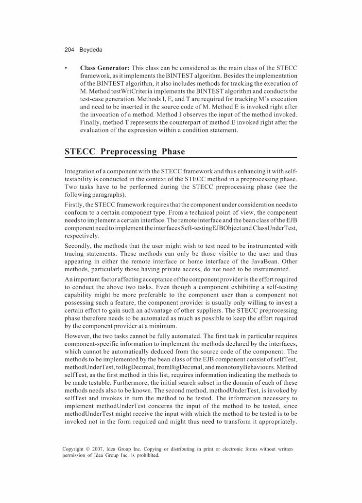
204 Beydeda
Copyright © 2007, Idea Group Inc. Copying or distributing in print or electronic forms without writtenpermission of Idea Group Inc. is prohibited.
• Class Generator: This class can be considered as the main class of the STECCframework, as it implements the BINTEST algorithm. Besides the implementationof the BINTEST algorithm, it also includes methods for tracking the execution ofM. Method testWrtCriteria implements the BINTEST algorithm and conducts thetest-case generation. Methods I, E, and T are required for tracking M’s executionand need to be inserted in the source code of M. Method E is invoked right afterthe invocation of a method. Method I observes the input of the method invoked.Finally, method T represents the counterpart of method E invoked right after theevaluation of the expression within a condition statement.
STECC Preprocessing Phase
Integration of a component with the STECC framework and thus enhancing it with self-testability is conducted in the context of the STECC method in a preprocessing phase.Two tasks have to be performed during the STECC preprocessing phase (see thefollowing paragraphs).Firstly, the STECC framework requires that the component under consideration needs toconform to a certain component type. From a technical point-of-view, the componentneeds to implement a certain interface. The remote interface and the bean class of the EJBcomponent need to implement the interfaces Seft-testingEJBObject and ClassUnderTest,respectively.Secondly, the methods that the user might wish to test need to be instrumented withtracing statements. These methods can only be those visible to the user and thusappearing in either the remote interface or home interface of the JavaBean. Othermethods, particularly those having private access, do not need to be instrumented.An important factor affecting acceptance of the component provider is the effort requiredto conduct the above two tasks. Even though a component exhibiting a self-testingcapability might be more preferable to the component user than a component notpossessing such a feature, the component provider is usually only willing to invest acertain effort to gain such an advantage of other suppliers. The STECC preprocessingphase therefore needs to be automated as much as possible to keep the effort requiredby the component provider at a minimum.However, the two tasks cannot be fully automated. The first task in particular requirescomponent-specific information to implement the methods declared by the interfaces,which cannot be automatically deduced from the source code of the component. Themethods to be implemented by the bean class of the EJB component consist of selfTest,methodUnderTest, toBigDecimal, fromBigDecimal, and monotonyBehaviours. MethodselfTest, as the first method in this list, requires information indicating the methods tobe made testable. Furthermore, the initial search subset in the domain of each of thesemethods needs also to be known. The second method, methodUnderTest, is invoked byselfTest and invokes in turn the method to be tested. The information necessary toimplement methodUnderTest concerns the input of the method to be tested, sincemethodUnderTest might receive the input with which the method to be tested is to beinvoked not in the form required and might thus need to transform it appropriately.

The STECC Framework 205
Copyright © 2007, Idea Group Inc. Copying or distributing in print or electronic forms without writtenpermission of Idea Group Inc. is prohibited.
Methods toBigDecimal and fromBigDecimal also necessitate component-specific infor-mation, which primarily concerns the objects processed during the execution of themethod to be tested. The objects processed, or more clearly their classes, need to beknown to implement injective functions and their inverses. Finally, monotonyBehavioursalso requires component-specific information. This information concerns the methodsinvoked during the execution of that which is to be tested. The monotony behavior ofeach of these methods needs to be known to implement monotonyBehaviours, whichobviously can only be hardly determined from the source code of the component.Even though some parts of the information necessary might be obtained on the basis ofthe component source code, the information necessary cannot be obtained entirely onthe basis of this source. The STECC framework, however, provides prototypes of thesemethods that have to be completed by the component provider. It should also be notedthat the component provider solely needs to implement these methods for classes andtheir methods developed in the context of the component. The corresponding methodsfor most standard Java classes are already available in classes Helper andMonotonyBehaviours of the STECC framework.Contrary to the first task, the second task that has to be performed during the STECCpreprocessing phase can be automated, even if not entirely. This task consists ofinserting tracing code for obtaining information for following purposes:
• Firstly, the tracing code has the objective of delivering the information required forthe dynamic generation of the control flow graph of the method to be tested. Theinformation required consists of the basic blocks within the method’s source codeand an adjacence matrix giving for each basic block those that can be entered nextafter its traversal. Assuming that the basic blocks are distinguished by unique IDs,successively executing the method and observing the basic blocks traversed canincrementally assemble this information.
• Secondly, another objective of the tracing code is to deliver the informationnecessary to validate that the inputs of the methods invoked during the executionof the method under test lie in the corresponding subsets of the methods’ domains.The information required consists of an ID identifying the method invoked, an IDidentifying the invocation and the input passed.
• Thirdly, the objective of the tracing code is also to collect the necessary informa-tion to determine the path traversed during the execution of the method under test.The path traversed can be uniquely determined by observing the edges selectedby the conditional statements. The edge selected by a conditional statementgenerally depends on a Boolean expression, and the edge selected can identifiedby observing the values of these expressions.
The STECC framework, or more clearly the Generator class, offers for this purpose thethree aforementioned methods I, E, and T. These methods have to be inserted at theappropriate positions in the source code of the method under test.
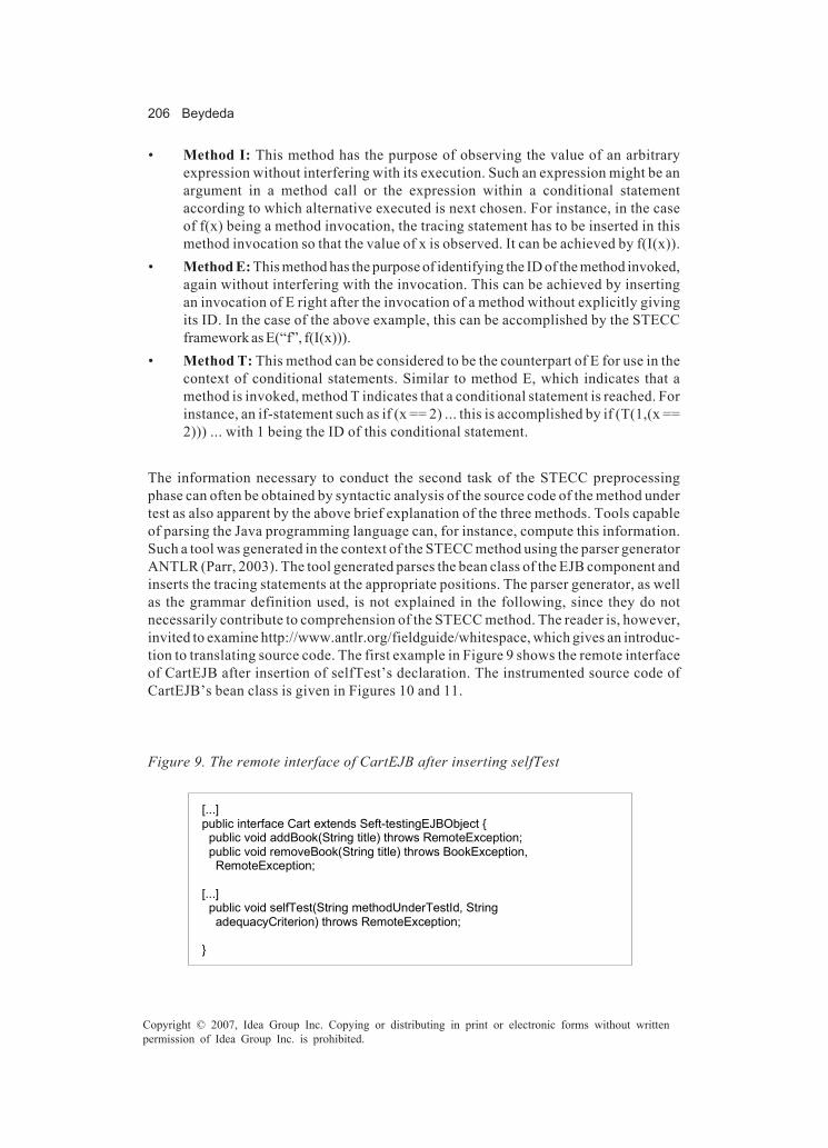
206 Beydeda
Copyright © 2007, Idea Group Inc. Copying or distributing in print or electronic forms without writtenpermission of Idea Group Inc. is prohibited.
• Method I: This method has the purpose of observing the value of an arbitraryexpression without interfering with its execution. Such an expression might be anargument in a method call or the expression within a conditional statementaccording to which alternative executed is next chosen. For instance, in the caseof f(x) being a method invocation, the tracing statement has to be inserted in thismethod invocation so that the value of x is observed. It can be achieved by f(I(x)).
• Method E: This method has the purpose of identifying the ID of the method invoked,again without interfering with the invocation. This can be achieved by insertingan invocation of E right after the invocation of a method without explicitly givingits ID. In the case of the above example, this can be accomplished by the STECCframework as E(“f”, f(I(x))).
• Method T: This method can be considered to be the counterpart of E for use in thecontext of conditional statements. Similar to method E, which indicates that amethod is invoked, method T indicates that a conditional statement is reached. Forinstance, an if-statement such as if (x == 2) ... this is accomplished by if (T(1,(x ==2))) ... with 1 being the ID of this conditional statement.
The information necessary to conduct the second task of the STECC preprocessingphase can often be obtained by syntactic analysis of the source code of the method undertest as also apparent by the above brief explanation of the three methods. Tools capableof parsing the Java programming language can, for instance, compute this information.Such a tool was generated in the context of the STECC method using the parser generatorANTLR (Parr, 2003). The tool generated parses the bean class of the EJB component andinserts the tracing statements at the appropriate positions. The parser generator, as wellas the grammar definition used, is not explained in the following, since they do notnecessarily contribute to comprehension of the STECC method. The reader is, however,invited to examine http://www.antlr.org/fieldguide/whitespace, which gives an introduc-tion to translating source code. The first example in Figure 9 shows the remote interfaceof CartEJB after insertion of selfTest’s declaration. The instrumented source code ofCartEJB’s bean class is given in Figures 10 and 11.
Figure 9. The remote interface of CartEJB after inserting selfTest
[...] public interface Cart extends Seft-testingEJBObject { public void addBook(String title) throws RemoteException; public void removeBook(String title) throws BookException, RemoteException; [...] public void selfTest(String methodUnderTestId, String adequacyCriterion) throws RemoteException; }
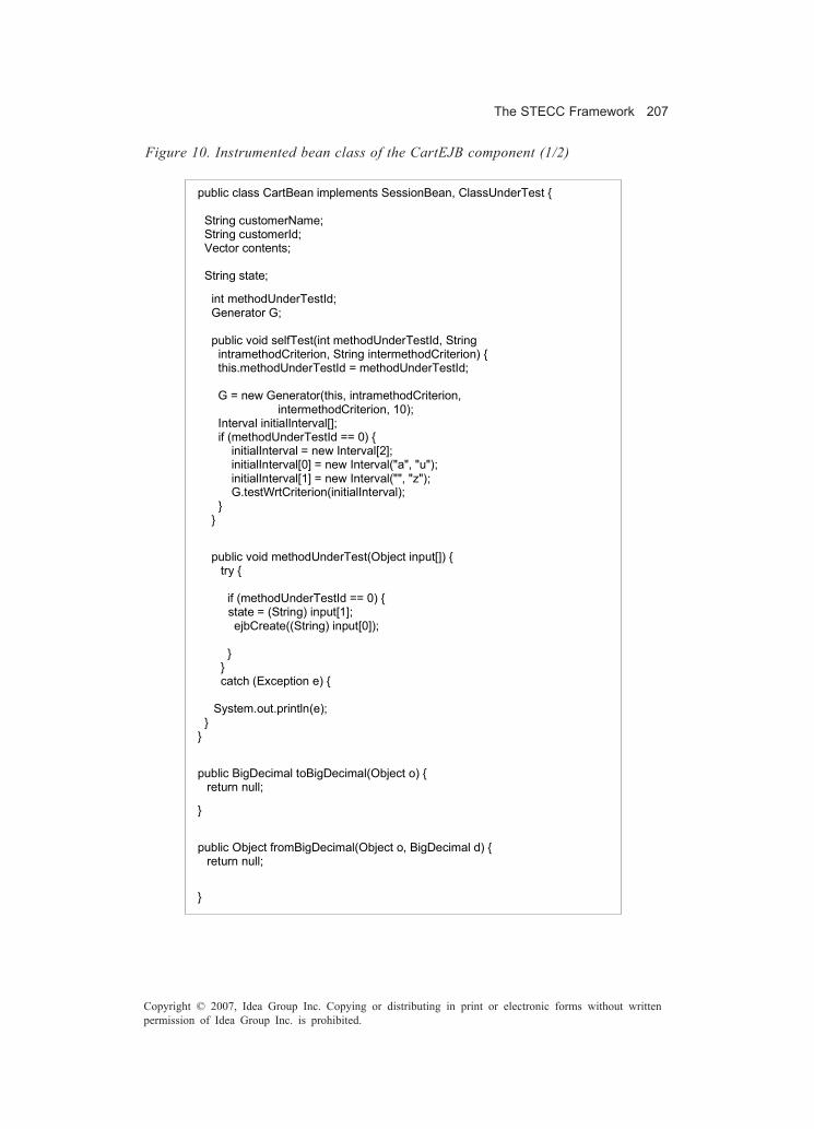
The STECC Framework 207
Copyright © 2007, Idea Group Inc. Copying or distributing in print or electronic forms without writtenpermission of Idea Group Inc. is prohibited.
Figure 10. Instrumented bean class of the CartEJB component (1/2)
public class CartBean implements SessionBean, ClassUnderTest { String customerName; String customerId; Vector contents; String state;
int methodUnderTestId; Generator G; public void selfTest(int methodUnderTestId, String intramethodCriterion, String intermethodCriterion) { this.methodUnderTestId = methodUnderTestId; G = new Generator(this, intramethodCriterion, intermethodCriterion, 10); Interval initialInterval[]; if (methodUnderTestId == 0) { initialInterval = new Interval[2]; initialInterval[0] = new Interval("a", "u"); initialInterval[1] = new Interval("", "z"); G.testWrtCriterion(initialInterval); } }
public void methodUnderTest(Object input[]) { try { if (methodUnderTestId == 0) {
state = (String) input[1]; ejbCreate((String) input[0]); } } catch (Exception e) {
System.out.println(e); } }
public BigDecimal toBigDecimal(Object o) { return null;
}
public Object fromBigDecimal(Object o, BigDecimal d) { return null;
}
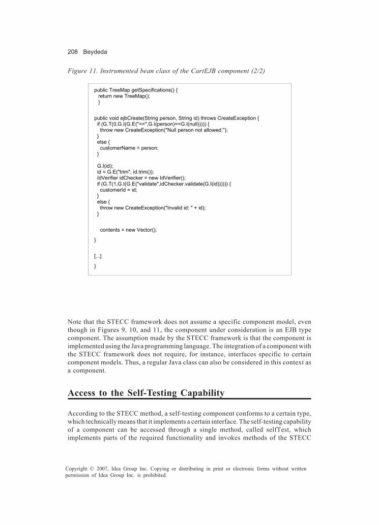
208 Beydeda
Copyright © 2007, Idea Group Inc. Copying or distributing in print or electronic forms without writtenpermission of Idea Group Inc. is prohibited.
Figure 11. Instrumented bean class of the CartEJB component (2/2)
public TreeMap getSpecifications() { return new TreeMap(); }
public void ejbCreate(String person, String id) throws CreateException { if (G.T(0,G.I(G.E("==",G.I(person)==G.I(null))))) { throw new CreateException("Null person not allowed."); } else { customerName = person; } G.I(id); id = G.E("trim", id.trim()); IdVerifier idChecker = new IdVerifier(); if (G.T(1,G.I(G.E("validate",idChecker.validate(G.I(id)))))) { customerId = id; } else { throw new CreateException("Invalid id: " + id); }
contents = new Vector();
}
[...]
}
Note that the STECC framework does not assume a specific component model, eventhough in Figures 9, 10, and 11, the component under consideration is an EJB typecomponent. The assumption made by the STECC framework is that the component isimplemented using the Java programming language. The integration of a component withthe STECC framework does not require, for instance, interfaces specific to certaincomponent models. Thus, a regular Java class can also be considered in this context asa component.
Access to the Self-Testing Capability
According to the STECC method, a self-testing component conforms to a certain type,which technically means that it implements a certain interface. The self-testing capabilityof a component can be accessed through a single method, called selfTest, whichimplements parts of the required functionality and invokes methods of the STECC

The STECC Framework 209
Copyright © 2007, Idea Group Inc. Copying or distributing in print or electronic forms without writtenpermission of Idea Group Inc. is prohibited.
framework transparently to the component user. This method is invoked with thefollowing two arguments:
• Argument methodUnderTestId: The first argument specifies the method to betested by its ID, which needs to be known by both parties.
• Argument adequacyCriterion: The second argument specifies the adequacycriterion according to which the method under consideration is to be tested.
A task that the component user has to conduct is the implementation of a client invokingmethod selfTest. The client, which might also be that implemented by the component userto access business logic, only needs to invoke this method and can thus have a single
Figure 12. Client for the access of the self-testing feature
[...] public class CartClient { public static void main(String[] args) { try { Context initial = new InitialContext(); Object objref = initial.lookup("java:comp/env/ejb/SimpleCart"); CartHome home = (CartHome) PortableRemoteObject.narrow(objref, CartHome.class); Cart shoppingCart = home.create("Duke DeEarl","123"); shoppingCart.selfTest(0, ".."); shoppingCart.remove(); System.exit(0); } catch (Exception ex) { System.err.println("Caught an unexpected exception!"); ex.printStackTrace(); System.exit(1); } }
Figure 13. Output produced by selfTest method
[STECC] Input: (k, =) [STECC] Covered: bc (bc, ) [STECC] Input: (a, =) [STECC] Covered: bd (bd, ) [STECC] Input: (k, k) [STECC] Covered: ac (ac, ) [...] [STECC] Input: (a, a) [STECC] Covered: ad (ad, ) [STECC] #Test cases: 4, #Iterations: 1862
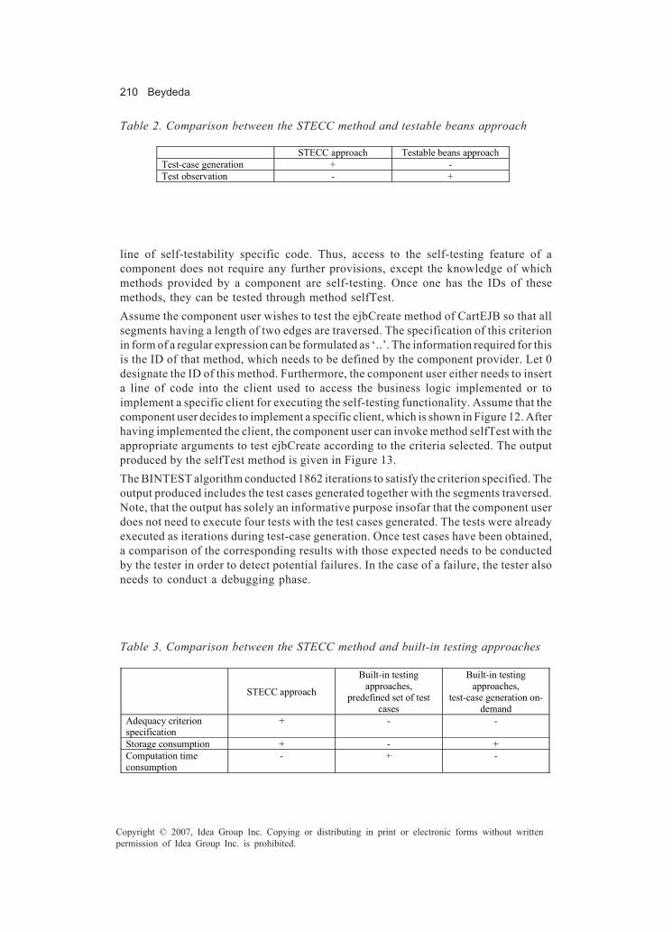
210 Beydeda
Copyright © 2007, Idea Group Inc. Copying or distributing in print or electronic forms without writtenpermission of Idea Group Inc. is prohibited.
line of self-testability specific code. Thus, access to the self-testing feature of acomponent does not require any further provisions, except the knowledge of whichmethods provided by a component are self-testing. Once one has the IDs of thesemethods, they can be tested through method selfTest.Assume the component user wishes to test the ejbCreate method of CartEJB so that allsegments having a length of two edges are traversed. The specification of this criterionin form of a regular expression can be formulated as ‘..’. The information required for thisis the ID of that method, which needs to be defined by the component provider. Let 0designate the ID of this method. Furthermore, the component user either needs to inserta line of code into the client used to access the business logic implemented or toimplement a specific client for executing the self-testing functionality. Assume that thecomponent user decides to implement a specific client, which is shown in Figure 12. Afterhaving implemented the client, the component user can invoke method selfTest with theappropriate arguments to test ejbCreate according to the criteria selected. The outputproduced by the selfTest method is given in Figure 13.The BINTEST algorithm conducted 1862 iterations to satisfy the criterion specified. Theoutput produced includes the test cases generated together with the segments traversed.Note, that the output has solely an informative purpose insofar that the component userdoes not need to execute four tests with the test cases generated. The tests were alreadyexecuted as iterations during test-case generation. Once test cases have been obtained,a comparison of the corresponding results with those expected needs to be conductedby the tester in order to detect potential failures. In the case of a failure, the tester alsoneeds to conduct a debugging phase.
STECC approach Testable beans approach Test-case generation + - Test observation - +
Table 2. Comparison between the STECC method and testable beans approach
Table 3. Comparison between the STECC method and built-in testing approaches
STECC approach
Built-in testing approaches,
predefined set of test cases
Built-in testing approaches,
test-case generation on-demand
Adequacy criterion specification
+ - -
Storage consumption + - + Computation time consumption
- + -

The STECC Framework 211
Copyright © 2007, Idea Group Inc. Copying or distributing in print or electronic forms without writtenpermission of Idea Group Inc. is prohibited.
Related Work
Testable Beans Approach
A lack of information can complicate testing of components in various aspects, andseveral approaches are proposed to tackle such difficulties. One of these approaches isproposed in Gao Gupta, Gupta, and Shim (2002). It addresses potential difficulties byimproving component testability. Component testability depends, besides other factors,on the ability of a component to support test execution and test observation, and can thusbe increased by augmenting a component with capabilities that support these tasks. Acomponent augmented with such capabilities is called a testable bean in this context,which indicates, at least technically, the target component model and framework of theapproach, namely the Enterprise JavaBeans component model and framework.One of the difficulties in testing a component is that the component user generally hasvery limited possibilities of observing the execution of tests. A component usually doesnot possess the necessary capabilities to allow the component user observation of testexecution, and such capabilities cannot be added to the component by the componentuser, since these capabilities generally require the source code and other detailedinformation. The necessary provisions thus need to be implemented by the componentprovider.A component, in this context an EJB component, needs to satisfy certain requirementsand possess certain features in order to become a testable bean:Firstly, a testable bean is deployable and executable. A testable bean can be used inexactly the same way as a regular component and does not require specific provisionsfor its operation.Secondly, a testable bean is traceable. A testable bean possesses certain capabilities thatpermit the component user to observe its behavior during a test, which would beencapsulated without such capabilities.Thirdly, a testable bean implements the test interface. A testable bean implements aconsistent and well-defined interface which allows access to the capabilities supportingits testing.Fourthly, a testable bean includes the necessary provisions to interact with externaltesting tools. The approach suggests functionally separate business logic from thetesting-specific logic at an architectural level.From a technical point of view, the test interface is probably the most obvious differencebetween a testable bean and a regular component that is visible to the component user.The test interface declares three methods. One of them initializes a test, giving the classand method to be tested, as well as the test case; another method executes the test asinitialized; and the last method finally evaluates the test. The methods declared by thetest interface and implemented by a testable bean can be used in two possible ways:Firstly, other tools can use the test interface. For instance, tools in the environment thatthe testable bean is embedded in can use it. In Gao et al. (2002) and Gao, Zhu, and Shim

212 Beydeda
Copyright © 2007, Idea Group Inc. Copying or distributing in print or electronic forms without writtenpermission of Idea Group Inc. is prohibited.
(2000), an environment containing two tools, called test agent and tracking agent, isdescribed. The first one triggers the tests, while the second one’s main purpose ismonitoring.Secondly, the testable bean itself can also use the test interface. A testable bean cancontain built-in test scripts that access the methods declared in the test interface, asnecessary. These test scripts, possibly comprising test cases, can initialize tests, executethem, and evaluate the results autonomously.
Built-In Test Approaches
A lack of information cannot only complicate the observation of test execution, but alsocomplicate the generation of test cases. The testable beans approach tackles thedifficulties in observing test execution and can also provide support for test-casegeneration in the form of built-in test scripts. Other authors also suggest built-in testingto support the component user’s tests. A component can contain the test cases orpossess facilities capable of generating test cases that the component can use to testitself and its own methods. The component user thus does not need to generate testcases, and difficulties that the component user would otherwise face cannot complicatethe component user’s tests.A built-in test approach can be found in Wang, King, and Wickburg (1999). Accordingto this approach, a component can operate in two modes, namely in normal mode andmaintenance mode. In normal mode, the built-in test capabilities are transparent to thecomponent user, and the component does not differ from other, non-built-in testing-enabled components. In maintenance mode, however, the component user can test thecomponent with the help of its built-in testing features. The component user can invokethe respective methods of the component, which execute the test, evaluate resultsautonomously, and print out a test summary. The authors describe a generic technicalframework for enhancing a component with built-in tests. One of the few assumptionsis that the component is implemented as a class. Under this assumption, it is suggestedto implement built-in testing by additional methods that either contain the test cases tobe used in hardwired form or are capable of generating them. The integral benefit of suchan implementation is that the methods for built-in testing can be passed to subclassesby inheritance.A built-in testing approach is also proposed in Baudry, Hanh, Jezequel, and Traon (2000),Baudry, Hanh, Jezequel, and Traon (2001), Deveaux, Frison, and Jezequel (2001),Jezequel, Deveaux, and Traon (2001), and Traon, Deveaux, and Jezequel (1999). Eventhough its authors call this approach a self-testing approach, it is referred to as a built-in testing approach for the sake of consistency. The features characterized by thoseauthors as self-testing significantly differ from those characterized as self-testing in thecontext of the STECC method, and resemble those of the above approach. This approachand that previously explained share several properties. Besides various modes ofoperation, a component is assumed to be implemented using object-oriented languages,particularly Java. Built-in testing is implemented by additional methods. Each component

The STECC Framework 213
Copyright © 2007, Idea Group Inc. Copying or distributing in print or electronic forms without writtenpermission of Idea Group Inc. is prohibited.
method that is testable with built-in testing capabilities possesses a testing method asa counterpart that invokes it with predefined arguments. An oracle is implemented bymeans of a component invariant — method pre- and postconditions. Invariants, pre- andpostconditions are determined based on the specification of the component andembedded in the source code of the component by the component provider. Thenecessary functionality to validate them and other functionality, for example, for tracingand reporting purposes, is implemented by a framework, which technically requires thatthe component, or more precisely the main class of the component, implements a certaininterface. Similarly to the above approach, the built-in testing capability can be passedto subclasses by inheritance. The authors propose to measure test completion by meansof fault injection, which is, however, not feasible in this context, since it requires sourcecode access, which the component user does not have. The component user thereforehas to assume that the built-in tests are sufficient.Another built-in test approach, the component+ approach, can be found in Atkinson andGroß (2002) and Hörnstein and Edler (1994). A shortcoming of the previous built-intesting approach is that test cases or a description of their generation need to be storedwithin the component. This can increase the resource consumption of the component,which, particularly taking into account that the built-in testing capabilities of a compo-nent are often required only once for deployment, can be an obstacle for its use. To avoidthis shortcoming, the authors define an architecture consisting of three types ofcomponents, namely BIT components, testers and handlers. The BIT components are thebuilt-in testing-enabled components. These components implement certain mandatoryinterfaces. Testers are components which access to the built-in testing capabilities of BITcomponents through the corresponding interfaces and which contain the test cases ina certain form. In the other approaches, a built-in testing-enabled component alsoencompasses the functionality of the testers. Here, however, they are separated with thebenefit that they can be developed and maintained independently, and that they do notincrease the resource requirements of BIT components in the operational environment.Finally, handlers are components in this architecture that do not contribute to testing,but can be required, for instance, to ensure recovery mechanisms in the case of failures.The presented built-in testing approaches do not restrict the tests that can be conductedinsofar that they are not constrained to specification-based testing. Built-in testingapproaches which are constrained to specification-based testing, such as those inEdwards (2000, 2001a, 2001b), and Martins, Toyota, and Yanagawa (2001), are notdiscussed here, since specification-based testing does not necessarily require provi-sions by the component provider. Assuming a specification is given, the component usercan obtain the appropriate test cases and test the component in principle without thecomponent provider’s support. Specification-based built-in testing capabilities un-doubtedly have the potential of simplifying component user’s tests by improvingcomponent testability, but the corresponding tasks can usually also be accomplished bythe component user.Note that approaches supporting and facilitating information exchange between thecomponent provider and component user, such as the component metadata, retro-components, reective wrapper, and component test-bench approaches, can also form a
214 Beydeda
Copyright © 2007, Idea Group Inc. Copying or distributing in print or electronic forms without writtenpermission of Idea Group Inc. is prohibited.
basis for built-in testing. Depending on the type of information, it is in principle possibleto automatically generate test cases using such information and conduct tests. Arespective application of the reective wrapper approach is given in Edwards (2000),Edwards (2001a), and Edwards (2001b).
Relation to the STECC Method
Testable Beans Approach
Both the testable beans approach and the STECC approach can be assigned to the secondcategory of approaches. They both aim at tackling the difficulties that the componentuser can encounter while testing a component. However, they address different difficul-ties in testing components and differ in various aspects. The testable-beans approachand the STECC approach differ in the following points:Firstly, the testable-beans approach supports the testing of component with an emphasison monitoring test execution. The STECC approach in contrast does not focus onmonitoring test execution, even though the STECC framework provides basic capabili-ties.Secondly, the testable-beans approach does not cover the generation of test cases. Testcases can be statically incorporated as part of built-in test scripts, but cannot bedynamically changed by the component user. The STECC approach allows generationof test cases according to the needs of the component user.Objectively, it is not possible to identify one approach as being better or dominating theother. Both approaches have their benefits and one approach can be more appropriatein certain circumstances than the other. Both, however, require specific provisions bythe component provider. The component user cannot add them to a component, but,since their existence can be a selection criterion in component evaluation, the componentprovider needs to carefully choose the approach with which to augment a component.
Built-In Testing Approaches
Similar to the STECC approach, the built-in testing approaches in Atkinson and Groß(2002), Baudry et al. (2000), Baudry et al. (2001), Deveaux et al. (2001), Hörnstein and Edler(1994), Jezequel et al. (2001), Traon et al. (1999), and Wang et al. (1999) can be assignedto the second category of component-testing approaches, taking into account a lack ofdevelopment-relevant information. Both aim at tackling difficulties in testing compo-nents caused by such a lack and the resulting difficulties in test-case generation inparticular. The STECC approach has the same objective, so the three approaches can bedirectly compared to it. A comparison highlights several differences, including thefollowing:

The STECC Framework 215
Copyright © 2007, Idea Group Inc. Copying or distributing in print or electronic forms without writtenpermission of Idea Group Inc. is prohibited.
Firstly, the built-in testing approaches explained here are static in that the componentuser cannot influence the test cases employed in testing. A component which is built-in testing enabled according to one of the explained approaches either contains apredetermined set of test cases or the generation, even if conducted on-demand duringruntime, solely depends on parameters which the component user cannot influence.Specifically, the component user cannot specify the adequacy criterion to be used fortest-case generation. However, the component user might wish to test all componentsto be assembled with respect to an unique adequacy criterion. Built-in testing ap-proaches, at least those described, do not allow this. The STECC approach does not havesuch a restriction. Adequacy criteria, even though constrained to control flow criteria,can be freely specified. Note that this restriction of built-in testing approaches dependson the size of the test-case set used. A large set of test cases generally satisfies moreadequacy criteria than a small set, but at the same time increases resource requirements.Secondly, built-in testing approaches using a predefined test-case set generally requiremore storage than the STECC approach. Specifically, large components with highinherent complexity might require a large set of test cases for their testing. A large setof test cases obviously requires a substantial amount of storage, which, however, canbe difficult to provide taking into account the additional storage required for executionof large components. This is also the case if test cases are stored separately from thecomponent, such as proposed by the component+ approach. In contrast, the STECCmethod does not require predetermined test cases and does not store the generated testcases.Thirdly, built-in testing approaches using a predefined test-case set generally requireless computation time at the component user’s site. In such a case, the computations fortest-case generation were already conducted by the component provider and obviouslydo not have to be repeated by the component user, who thus can save resources,particularly computation time, during testing. Savings in computation time are evenincreased if the component user needs to conduct tests frequently, for instance due tovolatility of the technical environment of the component. Storage and computation timeconsumption of a built-in testing-enabled component obviously depends on the imple-mentation of the corresponding capabilities, and the component provider needs todecide carefully between the two forms of implementation — predefined test case set orgeneration on-demand — in order to ensure a reasonable trade-off.The STECC approach has several benefits that make it more preferable than one of thebuilt-in testing approaches. Except for computation time consumption, the STECCapproach dominates the three explained built-in testing approaches and should be thefirst choice if a component is to be enhanced to facilitate a component user’s testing.However, in some circumstances, computation time might be crucial so that built-intesting approaches, particularly those that do not generate test cases on-demand butcontain a fixed set of test cases, are more preferable. Such a circumstance might be, asmentioned, one in which the technical environment of the component is volatile.

216 Beydeda
Copyright © 2007, Idea Group Inc. Copying or distributing in print or electronic forms without writtenpermission of Idea Group Inc. is prohibited.
Conclusion and Future Research
In this chapter, the STECC approach to testing components has been briefly introducedwith a detailed explanation of the STECC framework. The STECC framework provides atechnical platform for augmenting components developed using the Java programminglanguage such those according to the EJB component model with self-testability.So far, the STECC method can be used for intracomponent testing, that is, the testing ofcomponents in isolation. However, an issue also relevant for the component user is theintegration of components. The component user needs usually to carry out integrationtesting in order to gain confidence that the components used for building a systeminteract as intended.Our research in the future will particularly focus on integration testing of STECC self-testable components. We do believe that integration testing can also be conducted aspart of the self-testability feature of components. For this purpose, a protocol can bedefined among STECC self-testable components so that information required for integra-tion testing can be exchanged in an encapsulated manner, for example, encrypted. So, thiswould still satisfy the requirements of both the component user and the componentprovider. The component user can integration test without requiring detailed technicalinformation, which the component provider might not be willing to disclose.An important issue in the future will concern case studies. From an academic point ofview, the STECC approach seems to be very promising for testing COTS components.However, the STECC framework needs to be used and validated in industrial size projectin order to assess aspects such as acceptance by practitioners, costs, and benefits.
References
Atkinson, C., & Groß, H. G. (2002). Built-in contract testing in model-driven, component-based development. In ICSR Workshop on Component-based Development Pro-cesses (LNCS 2319, pp. 1-15). Berlin: Springer Verlag.
Basili, V. R., & Boehm, B. (2001). COTS-based systems top 10 list. IEEE Computer, 34(5),91-93.
Baudry, B., Hanh, V. L., Jezequel, J. M., & Traon, Y. L. (2000). Trustable components: Yetanother mutation-based approach. In Proceedings of the Symposium on MutationTesting (Mutation) (pp. 69-76). Retrieved from http://www.irisa.fr/triskell/perso_pro/bbaudry/mutation2000.pdf
Baudry, B., Hanh, V. L., Jezequel, J. M., & Traon, Y. L. (2001). Trustable components: Yetanother mutation-based approach. In W. E. Wong (Ed.), Mutation testing for thenew century (pp. 47-54). Dordrecht: Kluwer Academic Publishers.
Beydeda, S., & Gruhn, V. (2003a). BINTEST — Binary search-based test case generation.In Proceedings of the Computer Software and Applications Conference(COMPSAC) (pp. 28-33). Los Alamitos, CA: IEEE Computer Society Press.

The STECC Framework 217
Copyright © 2007, Idea Group Inc. Copying or distributing in print or electronic forms without writtenpermission of Idea Group Inc. is prohibited.
Beydeda, S., & Gruhn, V. (2003b). Merging components and testing tools: The self-testing COTS components (STECC) strategy. In Proceedings of the EUROMICROConference Component-based Software Engineering Track (EUROMICRO) (pp.107-114). Los Alamitos, CA: IEEE Computer Society Press.
Beydeda, S., & Gruhn, V. (2003c). The self-testing COTS components (STECC) strategy— a new form of improving component testability. In M. H. Hamza (Ed.), SoftwareEngineering and Applications Conference (SEA) (pp. 222-227). Anaheim: ACTAPress.
Beydeda, S., & Gruhn, V. (2003d). Test case generation according to the binary searchstrategy. In Proceedings of the International Symposium on Computer andInformation Sciences (ISCIS) (LNCS 2869, pp. 1000-1007). Berlin: Springer Verlag.
Borland Software Corporation (2003). Together ControlCenter. Retrieved June 2003,from http://www.togethersoft. com
Carney, D. & Long, F. (2000). What do you mean by COTS? Finally, a useful answer. IEEESoftware, 17(2), 83-86.
DeMichiel, L. G. (2002). Enterprise javabeans specification, version 2.1 (Technicalreport). Sun Microsystems. Retrieved from http://java.sun.com/products/ejb/docs.html
Deveaux, D., Frison, P., & Jezequel, J. M. (2001). Increase software trustability with self-testable classes in java. In Australian Software Engineering Conference (ASWEC)(pp. 3-11). Los Alamitos, CA: IEEE Computer Society Press.
Edwards, S. (2000). A framework for practical, automated black-box testing of compo-nent-based software. In Proceedings of the International ICSE Workshop onAutomated Program Analysis, Testing and Verification (pp. 106-114). New York:ACM Press.
Edwards, S. H. (2001a). A framework for practical, automated black-box testing ofcomponent-based software. Software Testing, Verification and Reliability, 11(2),97-111.
Edwards, S. H. (2001b). Toward reective metadata wrappers for formally specifiedsoftware components. In Proceedings of the OOPSLA Workshop Specificationand Verification of Component-based Systems (SAVCBS) (pp. 14-21). New York:ACM Press.
Gao, J., Gupta, K., Gupta, S., & Shim, S. (2002). On building testable software components.In Proceedings of the COTS-Based Software Systems (ICCBCC) (LNCS 2255, pp.108-121). Berlin: Springer Verlag.
Gao, J., Zhu, E. Y., & Shim, S. (2000). Monitoring software components and component-based software. In Proceedings of the Computer Software and ApplicationsConference (COMPSAC) (pp. 403-412). Los Alamitos, CA: IEEE Computer SocietyPress.
Gruhn, V., & Thiel, A. (2000). Komponentenmodelle: DCOM, JavaBeans, EnterpriseJavaBeans, CORBA. München: Addison-Wesley.

218 Beydeda
Copyright © 2007, Idea Group Inc. Copying or distributing in print or electronic forms without writtenpermission of Idea Group Inc. is prohibited.
Harrold, M. J. (2000). Testing: A roadmap. In The Future of Software Engineering,Special Volume of the Proceedings of the International Conference on SoftwareEngineering (ICSE) (pp. 63-72). New York: ACM Press.
Harrold, M. J., Liang, D., & Sinha, S. (1999). An approach to analyzing and testingcomponent-based systems. In Proceedings of the International ICSE WorkshopTesting Distributed Component-based Systems. Retrieved from http://www-static.cc.gatech.edu/aristolte/Publications/Papers/icse99-workshop.pdf
Hörnstein, J., & Edler, H. (1994). Test reuse in cbse using built-in tests. In Proceedingsof the Workshop on Component-based Software Engineering, Composing systemsfrom components, 2002. Retrieved from http://www.idt.mdh.se/~icc/cbse-ecbs2002/Jonas-Hornstein.pdf
Jezequel, J. M., Deveaux, D., & Traon, Y. L. (2001). Reliable objects: Lightweight testingfor oo languages. IEEE Software, 18(4), 76-83.
Martins, E., Toyota, C. M., & Yanagawa, R. L. (2001). Constructing self-testable softwarecomponents. In Proceedings of the International Conference on DependableSystems and Networks (DSN) (pp. 151-160). Los Alamitos, CA: IEEE ComputerSociety Press.
McIlroy, M. D. (1968, October 7-11). Mass produced software components. In P. Naur& B. Randell (Eds.), Software Engineering: Report of a Conference Sponsored bythe NATO Science Committee, Garmisch, Germany, NATO, Scientific AffairsDivision, Brussels.
Microsoft Corporation. (1995). The component object model specification. RetrievedJuly 2003, from http://www.microsoft.com/COM/resources/COM 1598D.ZIP
Morisio, M., & Torchiano, M. (2002). Definition and classification of COTS: A proposal.In Proceedings of the COTS-Based Software Systems (ICCBSS) (LNCS 2255, pp.165-175). Berlin: Springer Verlag.
Nolan, G. (1998). Decompiling Java. McGraw-Hill.Object Management Group (2002). Corba components. Retrieved June 2003, from http:/
/www.omg.org/cgi-bin/doc? formal/02-06-65.pdfOrso, A., Harrold, M. J., & Rosenblum, D. (2000). Component metadata for software
engineering tasks. In International Workshop on Engineering Distributed Ob-jects (EDO) (LNCS 1999, pp. 129-144). Berlin: Springer Verlag.
Parr, T. (2003). ANTLR website. Retrieved May 2003, from http://www.antlr.orgSun Microsystems (2001). The J2EE tutorial. Retrieved April 2003, from http://
java.sun.com/j2ee/tutorialSzyperski, C. (1998). Component software beyond object oriented programming. New
York: Addison-Wesley.Traon, Y. L., Deveaux, D., & Jezequel, J. M. (1999). Self-testable components: From
pragmatic tests to design-to-testability methodology. In Proceedings of theTechnology of Object-oriented Languages and Systems (TOOLS) (pp. 96-107). LosAlamitos, CA: IEEE Computer Society Press.

The STECC Framework 219
Copyright © 2007, Idea Group Inc. Copying or distributing in print or electronic forms without writtenpermission of Idea Group Inc. is prohibited.
Wang, Y., King, G., & Wickburg, H. (1999). A method for built-in tests in component-based software maintenance. In Proceedings of the European Conference onSoftware Maintenance and Reengineering (CSMR) (pp.186-189). Los Alamitos,CA: IEEE Computer Society Press.

220 Jorge, Gulías, & Cabrero
Copyright © 2007, Idea Group Inc. Copying or distributing in print or electronic forms without writtenpermission of Idea Group Inc. is prohibited.
Chapter X
Certifying Propertiesof Programs UsingTheorem Provers
J. Santiago Jorge, University of A Coruña, Spain
Víctor M. Gulías, University of A Coruña, Spain
David Cabrero, University of A Coruña, Spain
Abstract
Proving the correctness of a program, even the simplest one, is a complex and expensivetask; but, at the same time, it is one of the most important activities for a softwareengineer. In this chapter, we explore the use of theorem provers to certify propertiesof software; in particular, two different proof-assistants are used to illustrate themethod: Coq and PVS. Starting with a simple pedagogic example, a sort algorithm, wefinally reproduce the same approach in a more realistic scenario, a model of a block-allocation algorithm for a video-on-demand server.
Introduction
The difficulty of certifying the correctness of a programmakes the process very expen-sive in the cycle of software development. The most frequent validation method consistsof running the target program on a set of selected inputs. Unfortunately, although testingcan detect some bugs, it does not guarantee the correctness of our software because the

Certifying Properties of Programs Using Theorem Provers 221
Copyright © 2007, Idea Group Inc. Copying or distributing in print or electronic forms without writtenpermission of Idea Group Inc. is prohibited.
input set is generally incomplete (Ghezzi, Jazayeri, & Mandrioli, 1991). Formal methods,on the other hand, are proposed to complement traditional debugging techniques,assuring that some relevant property holds in any execution of the program (Clarke et al.,1996; Gunter & Mitchell, 1996). Through formal methods we understand tools, tech-niques, or languages that help us to develop certified software. Those methods state thata program is correct with respect to a particular specification. Two main techniques aretaken into account:
• Model checking: Proves that every possible state of the program satisfies aspecification
• Theorem proving: Derives a proof establishing that the program satisfies aspecification
It must be mentioned that formal methods are not intended to provide absolute reliability.The strength of formal methods resides in increasing the reliability (Clarke et al., 1996;Peled, 2001). They assist us in producing quality software by improving our confidencein programs. However, they are not the panacea for detecting software errors. Softwareverification methods do not guarantee the correctness of actual code, but rather allowthe verification of some abstract model of it. In addition, this verification is done withrespect to a given specification, which is written manually, and it is sometimes incompleteor may not express accurately the expected program behaviour. Besides, large systemsare difficult to study as a whole and therefore, they must be separated into small piecesin order to study each one.The literature about model checking (Bérard et al., 2001; Clarke, Grumberg, & Peled, 1999;Nielson, Nielson, & Hankin, 1999; Roscoe, 1994) is more prolific than that of theoremproving; however, in the present chapter we explore the use of theorem provers to checkparticular properties of software. These formal proofs should help us understandprograms better. Two approaches are considered:
• Manual proofs: We reason directly over the source code, applying techniques likeequational reasoning and structural induction. The proof methods are rigorous,though error-prone.
• Theorem provers: Besides assisting us in the development of the proofs, theyguarantee their correctness, preventing bugs that may be introduced in a hand-made proof.
Theorem provers are usually based on a logic, like first-order logic, higher-order logic,or a version of set theory which provides a framework for the formalization of mathemat-ics. Interactive proof assistants require a human user to give hints to the system.Depending on the degree of automation, significant proof tasks can be performedautomatically. Available implementations of generic theorem provers areACL2 (Kaufmann, Mannolios, & Moore, 2000a, 2000b), Coq (Bertot & Casteran, 2004;The Coq Development Team, 2004), HOL (Gordon & Melham, 1993), Isabelle (Paulson,

222 Jorge, Gulías, & Cabrero
Copyright © 2007, Idea Group Inc. Copying or distributing in print or electronic forms without writtenpermission of Idea Group Inc. is prohibited.
1990, 1994), LCF (Gordon, Milner, & Wadsworth 1979), PVS (Owre, Rushby, & Shankar,1992; Owre, Shankar, & Rushby, 1995), and so on.In our study, Coq and PVS are going to be used as theorem provers. By comparing twotheorem provers to each other (and also with handmade proofs), conclusions about theirsuitability can be stated. Coq is a proof tool developed at INRIA-Rocquencourt and ENS-Lyon. It provides a very rich and expressive typed language, a higher-order constructivelogic, and the possibility of extracting automatically functional programs from thealgorithmic content of the proofs. On the other hand, PVS is a verification system builton nearly 20 years experience at SRI. It integrates an expressive specification languageand powerful theorem-proving capabilities. PVS has been applied successfully to largeapplications in both academic and industrial settings. However, the proofs presented inthis chapter can also be constructed easily with other similar tools.For the implementation of our algorithms and models, we propose the use of functionalprogramming (Bird & Wadler 1988; Hudak, 1989; Paulson, 1996). Functional languagestreat computation as the evaluation of mathematical functions rather than the executionof commands, as done in imperative languages. A functional program consists of a setof (possibly recursive) definitions and the system evaluates (reduces) an expression tocompute a result value. The choice of using functional languages is due to a powerfulmathematical property of this paradigm: referential transparency, that assures thatequational reasoning — that is, f x is always f x — makes sense. As a matter of fact, themathematical way of proving theorems can be applied to functional programs.In this chapter, a list-sorting algorithm is firstly used as a running example for provingthe correctness of a piece of software. Even though this is a simple pedagogic example,some interesting problems arise when proving properties of an actual implementation.As concrete programming language, we choose the functional language ObjectiveCaml (Leroy et al., 2004; Weis & Leory, 1999) due to its wide coverage in the researchand academic environments. Then, we reproduce the same approach in a more realisticscenario, a model of a block allocation algorithm for a video-on-demand server (Gulías,Barreiro, & Freire, 2005), developed using the concurrent functional languageErlang (Armstrong, Virding, Wikström, & Williams, 1996)
Theorem Proofs
Before proving the correctness of a piece of software, we have to specify its algorithmsand the properties that define that correctness. Afterwards, a formal proof will bedeveloped to verify whether those properties hold or not.As said before, a classic sorting algorithm is chosen as our running example. Theimplementation in the functional language Objective Caml is done using an auxiliaryfunction ins. Given a relation le, an element x of a generic type ‘a and a list of elementswith appropriate type, ordered with respect to the relation le, the function ins returns anew list where the new element x has been placed in the right place, according to therelation le.
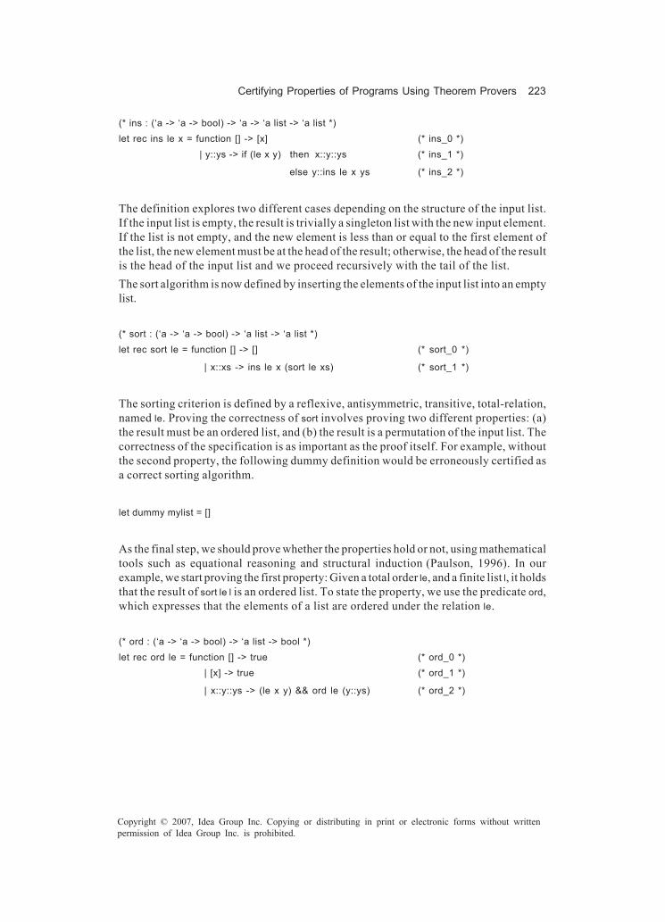
Certifying Properties of Programs Using Theorem Provers 223
Copyright © 2007, Idea Group Inc. Copying or distributing in print or electronic forms without writtenpermission of Idea Group Inc. is prohibited.
(* ins : (‘a -> ‘a -> bool) -> ‘a -> ‘a list -> ‘a list *)let rec ins le x = function [] -> [x] (* ins_0 *) | y::ys -> if (le x y) then x::y::ys (* ins_1 *)
else y::ins le x ys (* ins_2 *)
The definition explores two different cases depending on the structure of the input list.If the input list is empty, the result is trivially a singleton list with the new input element.If the list is not empty, and the new element is less than or equal to the first element ofthe list, the new element must be at the head of the result; otherwise, the head of the resultis the head of the input list and we proceed recursively with the tail of the list.The sort algorithm is now defined by inserting the elements of the input list into an emptylist.
(* sort : (‘a -> ‘a -> bool) -> ‘a list -> ‘a list *)let rec sort le = function [] -> [] (* sort_0 *)
| x::xs -> ins le x (sort le xs) (* sort_1 *)
The sorting criterion is defined by a reflexive, antisymmetric, transitive, total-relation,named le. Proving the correctness of sort involves proving two different properties: (a)the result must be an ordered list, and (b) the result is a permutation of the input list. Thecorrectness of the specification is as important as the proof itself. For example, withoutthe second property, the following dummy definition would be erroneously certified asa correct sorting algorithm.
let dummy mylist = []
As the final step, we should prove whether the properties hold or not, using mathematicaltools such as equational reasoning and structural induction (Paulson, 1996). In ourexample, we start proving the first property: Given a total order le, and a finite list l, it holdsthat the result of sort le l is an ordered list. To state the property, we use the predicate ord,which expresses that the elements of a list are ordered under the relation le.
(* ord : (‘a -> ‘a -> bool) -> ‘a list -> bool *)let rec ord le = function [] -> true (* ord_0 *)
| [x] -> true (* ord_1 *)
| x::y::ys -> (le x y) && ord le (y::ys) (* ord_2 *)

224 Jorge, Gulías, & Cabrero
Copyright © 2007, Idea Group Inc. Copying or distributing in print or electronic forms without writtenpermission of Idea Group Inc. is prohibited.
Hence, the property to certify is stated as:
• Lemma 1: For every finite list l, every relation le and every element x ofappropriate type:
ord le l ⇒ ord le (ins le x l)
Proof: By structural induction on l.
Base case: l = [].
ord le (ins le x [])
= ord le [x] { (1) by definition of ins_0 (left to right) } = true { (2) by definition of ord_1 (left to right) }
The equality has been proved starting with one expression and replacing “equalsby equals” until the other has been achieved. Each step has been justifiedunfolding a definition; in other cases, we may apply a previously proved property,the induction hypothesis, and so on.
Induction step: l = y::ys. The induction hypothesis is ord le (ins le x ys). There aretwo alternatives:
1. le x y.
ord le (ins le x (y::ys))
= ord le (x::y::ys) {(1) by definition of ins_1 (left to right)}= le x y ∧ ord le (y::ys) {(2) by definition of ord_2 (left to right)}= ord le (y::ys) {(3) by case analysis le x y}= true {(4) by hypothesis}
2. not (le x y) ⇒ le y x. We take into account three different sub-cases:
a. ys = [].
ord le (ins le x (y::[]))
= ord le (y::ins le x []) {(1) by definition of ins_2 (left to right)}

Certifying Properties of Programs Using Theorem Provers 225
Copyright © 2007, Idea Group Inc. Copying or distributing in print or electronic forms without writtenpermission of Idea Group Inc. is prohibited.
= ord le (y::[x]) {(2) by definition of ins_0 (left to right)}= le y x ∧ ord le [x] {(3) by definition of ord_2 (left to right)}= ord le [x] {(4) by case analysis le y x}= true {(5) by definition of ord_1 (left to right)}
b. ys = z::zs ∧ le x z.
ord le (ins le x (y::z::zs))
= ord le (y::ins le x (z::zs)) {(1) by definition of ins_2 (left to right)}= ord le (y::x::z::zs) {(2) by definition of ins_1 (left to right)}= le y x ∧ ord le (x::z::zs) {(3) by definition of ord_2 (left to right)}= ord le (x::z::zs) {(4) by case analysis le y x}= ord le (ins le x (z::zs)) {(5) by definition of ins_1 (right to left)}= true {(6) by induction hypothesis}
c. ys = z::zs ∧ not (le x z).
ord le (ins le x (y::z::zs))
= ord le (y::ins le x (z::zs)) {(1) def. of ins_2 (left to right)}= ord le (y::z::ins le x zs) {(2) def. of ins_2 (left to right)}= le y z ∧ ord le (z::ins le x zs) {(3) def. of ord_2 (left to right)}= ord le (z::ins le x zs) {(4) hypoth. ord le (y::z::zs)}= ord le (ins le x (z::zs)) {(5) def. of ins_2 (right to left)}= true {(6) by induction hypothesis}
The proof of the law ends here. Q.E.D.
This lemma can be used now to demonstrate new properties, as shown in the followingtheorem.
• Theorem 1: For every finite list l,
ord le (sort le l)

226 Jorge, Gulías, & Cabrero
Copyright © 2007, Idea Group Inc. Copying or distributing in print or electronic forms without writtenpermission of Idea Group Inc. is prohibited.
Proof: By structural induction on l.
Base Case: l = [].
ord le (sort le [])
= ord le [] {(1) by definition of sort_0 (left to right)}= true {(2) by definition of ord.0 (left to right)}
Induction step: l = x::xs. The induction hypothesis is sort le xs.
ord le (sort le (x::xs))
= ord le (ins le x (sort le xs)) {(1) by definition of sort_1 (left to right)}= true {(2) by lemma 1 and by induction
hypothesis}
So, it has been stated that the program sort returns an ordered list. Q.E.D.
To complete the certification, we should demonstrate the second property: sort returnsa permutation of the input list. We could provide the definition of permutation of a listand show that the output of sort is a permutation of the input list. However, we can alsoshow that the input and output of sort are the same multiset (see chapter 6 of Paulson,1996). In this case, we define count as that which returns the number of occurrences ofan element w in a list l.
(* val count : ‘a -> ‘a list -> int *)let rec count w = function [] -> 0 (* count_0 *) | x::xs -> if w = x then 1 + count w xs (* count_1 *)
else count w xs (* count_2 *)
It is necessary to prove that for every list l and for all element w of appropriate type, itholds that count w l = count w (sort l). This can be proved using the following auxiliary laws.
• Lemma 2: For all finite lists l1 and l2 and all elements w and n of appropriate type:
count w l1 = count w l2 ⇒ count w (cons n l1) = count w (cons n l2)
Proof: By equational reasoning. There are two sub-cases:

Certifying Properties of Programs Using Theorem Provers 227
Copyright © 2007, Idea Group Inc. Copying or distributing in print or electronic forms without writtenpermission of Idea Group Inc. is prohibited.
� w = n
count w (n::l1)
= 1 + count w l1 {(1) by definition of count_1 (left to right)}= 1 + count w l2 {(2) by hypothesis}= count w (n::l2) {(3) by definition of count_1 (right to left)}
� w ≠ n. The proof is similar to the previous case. Q.E.D.
• Lemma 3: For every finite list l and all elements w, n and m of appropriate type:
count w (n::m::l) = count w (m::n::l)
Proof: Equational reasoning using the definition of count easily solves this lemma.There are four sub-cases. Q.E.D.
Now, we prove that ins le n l has the same number of occurrences of every element in n::l.
• Lemma 4: For every finite list l, every relation le and all elements w, n ofappropriate type:
count w (ins le n l) = count w (n::l)
Proof: By structural induction on l:
Base case: l = [].
count w (ins le n [])
= count w [n] {(1) by definition of ins_0 (left to right)}
Induction step: l = x::xs. There are two sub-cases:
� le n x
count w (ins le n (x::xs))
= count w (n::x::xs) {(1) by definition of ins_1 (left to right)}
� not (le n x)
count w (ins le n (x::xs))
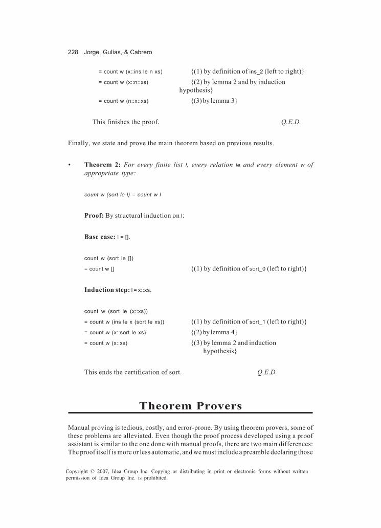
228 Jorge, Gulías, & Cabrero
Copyright © 2007, Idea Group Inc. Copying or distributing in print or electronic forms without writtenpermission of Idea Group Inc. is prohibited.
= count w (x::ins le n xs) {(1) by definition of ins_2 (left to right)}= count w (x::n::xs) {(2) by lemma 2 and by induction
hypothesis}= count w (n::x::xs) {(3) by lemma 3}
This finishes the proof. Q.E.D.
Finally, we state and prove the main theorem based on previous results.
• Theorem 2: For every finite list l, every relation le and every element w ofappropriate type:
count w (sort le l) = count w l
Proof: By structural induction on l:
Base case: l = [].
count w (sort le [])
= count w [] {(1) by definition of sort_0 (left to right)}
Induction step: l = x::xs.
count w (sort le (x::xs))
= count w (ins le x (sort le xs)) {(1) by definition of sort_1 (left to right)}= count w (x::sort le xs) {(2) by lemma 4}= count w (x::xs) {(3) by lemma 2 and induction
hypothesis}
This ends the certification of sort. Q.E.D.
Theorem Provers
Manual proving is tedious, costly, and error-prone. By using theorem provers, some ofthese problems are alleviated. Even though the proof process developed using a proofassistant is similar to the one done with manual proofs, there are two main differences:The proof itself is more or less automatic, and we must include a preamble declaring those

Certifying Properties of Programs Using Theorem Provers 229
Copyright © 2007, Idea Group Inc. Copying or distributing in print or electronic forms without writtenpermission of Idea Group Inc. is prohibited.
functions, types, and so on that we intend to use in the description of the algorithm andits properties.Using the running example in the previous section, we describe the proof process usingboth Coq and PVS as theorem provers. From now on, the code of the examples as wellas the user’s input will be typed in Arial font whilst the system answer will be in italics.
The Preamble
The first task to be carried out is to declare all the resources required for the proof: typesof data, structures, hypotheses, axioms, and so on. Let us see this preamble with the proofassistant Coq. For an introduction to Coq, refer to Giménez (1998), Huet, Kahn, G., andPaulin-Mohring (2002).First, we axiomatize a generic type to contain the elements of the lists in our sortingalgorithm. In addition, Coq demands that the decidability of the equality should beexplicitly stated for the new type.
Variable A: Set.
Hypothesis eq_dec: forall a b: A, {a=b}+{~a=b}.
A total relation order over A, leA, is introduced together with some hypotheses about itsproperties.
Variable leA: A -> A -> Prop.Hypothesis leA_refl: forall a: A, (leA a a).Hypothesis leA_trans: forall a b c: A, (leA a b)->(leA b c)->(leA a c).Hypothesis leA_antisym: forall a b: A, (leA a b)->(leA b a)->a=b.Hypothesis leA_tot: forall a b: A, (leA a b) \/ (leA b a).
We also state that relation leA is decidable from a computational point of view.
Hypothesis leA_dec: forall a b: A, {leA a b}+{~(leA a b)}.
Finally, we use the predefined definition of lists of the system Coq.
Inductive list (A : Set):Set := nil : list A | cons : A -> list A -> list A
The lists are parametric inductive definitions with two constructors: nil and cons. Theformer represents the empty list, and the latter takes an element of a generic type A anda list of elements of type A to construct another list of type list A. The lists follow thisinduction principle:
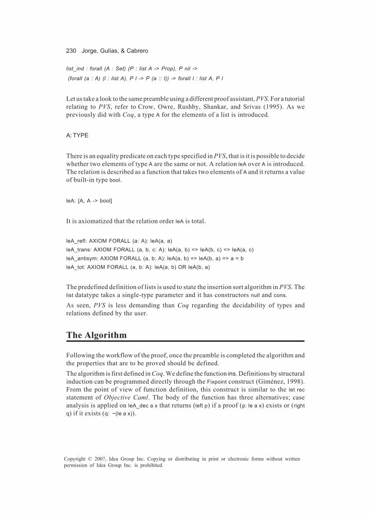
230 Jorge, Gulías, & Cabrero
Copyright © 2007, Idea Group Inc. Copying or distributing in print or electronic forms without writtenpermission of Idea Group Inc. is prohibited.
list_ind : forall (A : Set) (P : list A -> Prop), P nil ->
(forall (a : A) (l : list A), P l -> P (a :: l)) -> forall l : list A, P l
Let us take a look to the same preamble using a different proof assistant, PVS. For a tutorialrelating to PVS, refer to Crow, Owre, Rushby, Shankar, and Srivas (1995). As wepreviously did with Coq, a type A for the elements of a list is introduced.
A: TYPE
There is an equality predicate on each type specified in PVS, that is it is possible to decidewhether two elements of type A are the same or not. A relation leA over A is introduced.The relation is described as a function that takes two elements of A and it returns a valueof built-in type bool.
leA: [A, A -> bool]
It is axiomatized that the relation order leA is total.
leA_refl: AXIOM FORALL (a: A): leA(a, a)leA_trans: AXIOM FORALL (a, b, c: A): leA(a, b) => leA(b, c) => leA(a, c)leA_antisym: AXIOM FORALL (a, b: A): leA(a, b) => leA(b, a) => a = bleA_tot: AXIOM FORALL (a, b: A): leA(a, b) OR leA(b, a)
The predefined definition of lists is used to state the insertion sort algorithm in PVS. Thelist datatype takes a single-type parameter and it has constructors null and cons.As seen, PVS is less demanding than Coq regarding the decidability of types andrelations defined by the user.
The Algorithm
Following the workflow of the proof, once the preamble is completed the algorithm andthe properties that are to be proved should be defined.The algorithm is first defined in Coq. We define the function ins. Definitions by structuralinduction can be programmed directly through the Fixpoint construct (Giménez, 1998).From the point of view of function definition, this construct is similar to the let recstatement of Objective Caml. The body of the function has three alternatives; caseanalysis is applied on leA_dec a x that returns (left p) if a proof (p: le a x) exists or (rightq) if it exists (q: ~(le a x)).

Certifying Properties of Programs Using Theorem Provers 231
Copyright © 2007, Idea Group Inc. Copying or distributing in print or electronic forms without writtenpermission of Idea Group Inc. is prohibited.
Fixpoint ins (a: A) (l: (list A)) {struct l}: (list A) := match l with nil => (cons a l) | (cons x xs) => match (leA_dec a x) with (left p) => (cons a l)
| (right q) => (cons x (ins a xs)) end
end.
The function is defined by structural induction on the second argument, list l. This isdenoted by {struct l}. In order to be accepted, this argument has to decrease structurallyin the recursive calls. It is also possible to define functions in Coq by general recursionspecifying a well-founded relation that guarantees termination (Giménez, 1998; Bertot &Casteran, 2004).
Now, using ins, the function sort can be defined.
Fixpoint sort (l: (list A)) {struct l}: (list A) := match l with nil => nil | (cons x xs) => (ins x (sort xs))
end.
On the other hand, in PVS the function ins is a recursive declaration that takes an elementof type A and a list, and it returns a new list.
ins(a: A, l: list[A]): RECURSIVE list[A] = CASES l OF null: cons(a, null), cons(x, xs): IF leA(a, x) THEN cons(a, l) ELSE cons(x, ins(a, xs)) ENDIF ENDCASES
MEASURE length(l)
There is a MEASURE function specified in order to guarantee that the definition is total.PVS uses the MEASURE to generate a proof obligation to ensure that the function is total.This proof obligation is generated as a type-correctness condition (TCC). In this case,this clause is used to show that ins terminates by indicating the argument that decreasesthrough recursive calls. The proof of this TCC is postponed until the algorithm and itsproperties have been specified.The insertion sort function is defined by using the definition of ins.
sort(l: list[A]): RECURSIVE list[A] = CASES l OF null: null, cons(x, xs): ins(x, sort(xs)) ENDCASES
MEASURE length(l)

232 Jorge, Gulías, & Cabrero
Copyright © 2007, Idea Group Inc. Copying or distributing in print or electronic forms without writtenpermission of Idea Group Inc. is prohibited.
As shown, Coq and PVS have different approaches to the definition of primitive recursivefunctions. Coq is more restrictive in the sense that it demands to use structural inductionon one argument of the function. Although this restriction improves mathematicalsoundness, it is less flexible than the approach chosen by PVS, particularly with complexrecursive definitions.
The Properties
After defining the algorithm, the properties to be proved have to be stated as done in thefirst section.
• The result must be an ordered list: In Coq, the predicate ord expresses this firstproperty: whether a list is ordered with respect to the predicate leA or not. It isdefined inductively. These three clauses are mathematical axioms translated intoCoq.
Inductive ord: (list A) -> Prop := | ord_1 : (ord nil) | ord_2 : forall a: A, (ord (cons a nil)) | ord_3 : forall a b: A, forall l: (list A), (ord (cons b l)) -> (leA a b) -> (ord (cons a (cons b l))).
In PVS, the predicate ord specifies whether a list is ordered or not with respect to a relationorder. It is a recursive declaration with a MEASURE clause.
ord(l: list[A]): RECURSIVE bool = CASES l OF
null: TRUE, cons(x, xs): CASES xs OF null: TRUE, cons(y,ys): leA(x,y) AND ord(xs) ENDCASES
ENDCASES
MEASURE length(l)
• The result is a permutation of the input list: As in the manual proof (first sec-tion), the second property is specified by means of an auxiliary function count thatcounts the number of occurrences of an element in a list. Therefore, it is necessaryto prove that for every list l and for any element w of appropriate type, it holds thatcount w l = count w (sort l). In Coq, count can be defined using Fixpoint.

Certifying Properties of Programs Using Theorem Provers 233
Copyright © 2007, Idea Group Inc. Copying or distributing in print or electronic forms without writtenpermission of Idea Group Inc. is prohibited.
Fixpoint count (w:A) (l: (list A)) {struct l}: nat := match l with nil => O
| (cons x xs) => match (eq_dec w x) with | (left p) => (S (count w xs)) | (right q) => (count w xs)end
end.
And the lemma that states the desired property is:
Lemma count_sort: forall l: (list A), forall w:A,
(count w l)=(count w (sort l)).
In PVS, count is defined as a direct translation of the Caml program in first section.
count(w: A, l: list[A]): RECURSIVE nat = CASES l OF null: 0,
cons(x, xs): IF w = x THEN 1 + count(w, xs) ELSE count(w, xs) ENDIF ENDCASES
MEASURE length(l)
To guarantee termination, the MEASURE clause indicates that the list decreasesthrough recursive calls. With count, we state the desired property:
count_sort: THEOREM FORALL (l: list[A]), (w: A):
count(w, l) = count(w, sort(l))
As seen, there are no remarkable differences between Coq and PVS in the example.
The Proof
As the final step, the properties defined in the previous section have to be proved. Atheorem prover assists by applying logical rules during the proof and, in some cases,proving the theorems automatically. Frequently, the theorem prover cannot perform theproof automatically and the problem needs to be decomposed by introducing interme-diate lemmas and properties to guide the system, and, even, manually pointing out thelogical rules to be applied.In Coq, each property constitutes a goal to be proven. The proof of a property is carriedout applying successive tactics that solve the goal or that transform the current goal into

234 Jorge, Gulías, & Cabrero
Copyright © 2007, Idea Group Inc. Copying or distributing in print or electronic forms without writtenpermission of Idea Group Inc. is prohibited.
new subgoals. The proof ends when no subgoal remains unproved. This methodology,initially developed in the LCF system, allows a total control over the proof. In proof mode,the system displays the current goal below a double line and the hypothesis above theline.In PVS, on the other hand, each proof goal is a sequent. A sequent is a formula like:
(A1 ∧ A2 ∧ ... ∧ An) ⇒ (C1 ∨ C2 ∨ ... ∨ Cm)
where each subformula Ai is an antecedent, and each subformula Ci is a consequent. Itneeds to be established that the conjunction of the formulas above the line implies thedisjunction of the formulas below the line. A proof starts with no antecedent and a singleconsequent. This is the initial goal. In PVS, a sequent is displayed as:
-1 A1 For example:
. . . ======
. . . ======
-n An ord_ins_aux :------- |-------- 1 C1 [1] FORALL (l: list[A]), (a, b: A): .
. . ======
. . . ======
ord(cons(a,l)) => leA(a,b) => ord(cons(a,ins(b,l)))
m Cm
PVS waits for a prover command to transform the sequent. A PVS proof command canbe applied either to a consequent or an antecedent. A command may specify the linenumber in the current goal where it should be applied.In both Coq and PVS, some tactics or commands may split the proof into branches orsubgoals. The law is proved when all branches are finished.
The Result of sort must be an Ordered List
Coq The lemma 1, presented in the first section, is split into two simpler ones. The firstone, which comprehends the second alternative of that mentioned lemma, is stated asfollows:
∀l ∈ (listA), ∀a,b ∈ A, ord(a :: l) ∧ a <= b ⇒ ord(a :: ins b l)
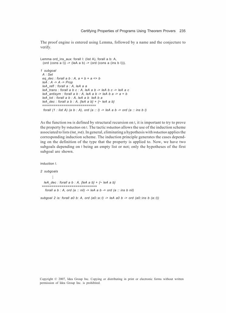
Certifying Properties of Programs Using Theorem Provers 235
Copyright © 2007, Idea Group Inc. Copying or distributing in print or electronic forms without writtenpermission of Idea Group Inc. is prohibited.
The proof engine is entered using Lemma, followed by a name and the conjecture toverify.
Lemma ord_ins_aux: forall l: (list A), forall a b: A, (ord (cons a l)) -> (leA a b) -> (ord (cons a (ins b l))).
1 subgoal A : Set eq_dec : forall a b : A, a = b + a <> b leA : A -> A -> Prop leA_refl : forall a : A, leA a a leA_trans : forall a b c : A, leA a b -> leA b c -> leA a c leA_antisym : forall a b : A, leA a b -> leA b a -> a = b leA_tot : forall a b : A, leA a b leA b a leA_dec : forall a b : A, {leA a b} + {~ leA a b} ============================ forall (1 : list A) (a b : A), ord (a :: l) -> leA a b -> ord (a :: ins b l)
As the function ins is defined by structural recursion on l, it is important to try to provethe property by induction on l. The tactic induction allows the use of the induction schemeassociated to lists (list_ind). In general, eliminating a hypothesis with induction applies thecorresponding induction scheme. The induction principle generates the cases depend-ing on the definition of the type that the property is applied to. Now, we have twosubgoals depending on l being an empty list or not; only the hypotheses of the firstsubgoal are shown.
induction l.
2 subgoals
...
leA_dec : forall a b : A, {leA a b} + {~ leA a b} ============================ forall a b : A, ord (a :: nil) -> leA a b -> ord (a :: ins b nil)
subgoal 2 is: forall a0 b: A, ord (a0::a::l) -> leA a0 b -> ord (a0::ins b (a::l))

236 Jorge, Gulías, & Cabrero
Copyright © 2007, Idea Group Inc. Copying or distributing in print or electronic forms without writtenpermission of Idea Group Inc. is prohibited.
intros. 2 subgoals . . . leA_dec : forall a b : A, {leA a b}+{~ leA a b} a : A b : A H : ord (a :: nil) H0 : leA a b ============================ ord (a :: ins b nil) subgoal 2 is: ...
The tactic intros transfers universal quantifiers and the premises of the implications, in order, from the current goal to the hypothesis context.
simpl. 2 subgoals . . . ============================ ord (a :: b :: nil) subgoal 2 is: ...
The tactic simpl carries out a simplification doing all the possible β-reductions (the β-reduction expresses the idea of function application). Here, the use of this tactic corresponds to the manual step (first section) in which equational reasoning over the definition of ins was realized.
constructor 3. 3 subgoals . . . ============================ ord (b :: nil) subgoal 2 is: leA a b subgoal 3 is: ...
When the current subgoal of the proof is an inductive type, the nth constructor of the type definition is applied by means of the tactic Constructor n. It is now when the third introduction rule of ord is used. This replaces the actual subgoal with two new ones: ord (b :: nil) and leA a b.
Then, the second introduction rule of ord is applied. This terminates the first subgoal.In order to solve the second subgoal, we just have to notice that the goal is available ashypothesis H0 in the hypothesis context. Such an easy step is solved by an automatictactic, called auto.
constructor 2. auto.
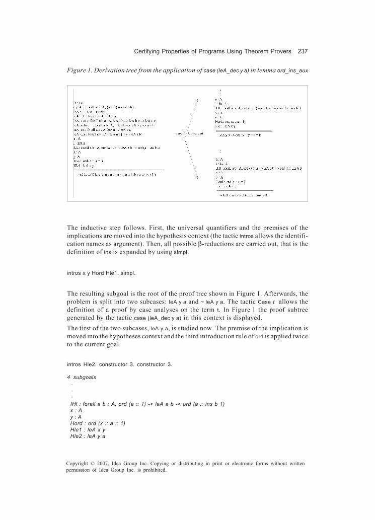
Certifying Properties of Programs Using Theorem Provers 237
Copyright © 2007, Idea Group Inc. Copying or distributing in print or electronic forms without writtenpermission of Idea Group Inc. is prohibited.
The inductive step follows. First, the universal quantifiers and the premises of theimplications are moved into the hypothesis context (the tactic intros allows the identifi-cation names as argument). Then, all possible β-reductions are carried out, that is thedefinition of ins is expanded by using simpl.
intros x y Hord Hle1. simpl.
The resulting subgoal is the root of the proof tree shown in Figure 1. Afterwards, theproblem is split into two subcases: leA y a and ~ leA y a. The tactic Case t allows thedefinition of a proof by case analyses on the term t. In Figure 1 the proof subtreegenerated by the tactic case (leA_dec y a) in this context is displayed.The first of the two subcases, leA y a, is studied now. The premise of the implication ismoved into the hypotheses context and the third introduction rule of ord is applied twiceto the current goal.
intros Hle2. constructor 3. constructor 3.
4 subgoals
. . . ====== IHl : forall a b : A, ord (a :: 1) -> leA a b -> ord (a :: ins b 1) x : A y : A Hord : ord (x :: a :: 1) Hle1 : leA x y Hle2 : leA y a
Figure 1. Derivation tree from the application of case (leA_dec y a) in lemma ord_ins_aux
Figure 1. Derivation tree from the application of in lemma

238 Jorge, Gulías, & Cabrero
Copyright © 2007, Idea Group Inc. Copying or distributing in print or electronic forms without writtenpermission of Idea Group Inc. is prohibited.
============================ ord (a :: 1)
subgoal 2 is: leA y asubgoal 3 is: leA x ysubgoal 4 is: ...
inversion Hord. 4 subgoals . . . Hord : ord (x :: a :: l) Hle1 : leA x y Hle2 : leA y a H1 : ord (a :: l) H3 : leA x a ============================ ord (a :: l) subgoal 2 is: leA y a subgoal 3 is: leA x y subgoal 4 is: ...
One of the premises of the inductive hypothesis ord (x :: a :: l) is the current subgoal. The introduction rules of an inductive type are derived with the tactic inversion. Every possible premise is generated.
Proving the actual subgoal, and the two successive ones, is trivial when using thehypotheses: H1, Hle2 and Hle1.The second subcase, ~ leA y a, whose proof is similar to the previous alternative, iscarried out now. The premise of the implication is moved into the hypotheses context andthe third introduction clause of ord is used.
intros Hle2. constructor 3.
2 subgoals
. . . ====== ============================ ord (a :: ins y l)
subgoal 2 is: leA x a

Certifying Properties of Programs Using Theorem Provers 239
Copyright © 2007, Idea Group Inc. Copying or distributing in print or electronic forms without writtenpermission of Idea Group Inc. is prohibited.
apply IHl. 3 subgoals . . . ============================ ord (a :: l) subgoal 2 is: leA a y subgoal 3 is: leA x a
The current goal may be obtained from the induction hypothesis IHl, provided the truth of ord (a :: l) and leA a b are established. Tactic apply fulfills this piece of reasoning.
The first subgoal is solved by the inversion tactic analysing the hypothesis Hord. Thesecond subgoal is achieved with the help of the auxiliary law not_leA_leA which statesthat ∀a,b ∈ A, a ≤ b ⇒ b ≤ a and that is easy to prove. Finally, the last goal is also provedanalysing the hypothesis Hord.
inversion Hord; auto.apply not_leA_leA; auto.inversion Hord; auto.
Qed.
The demonstration of the law ord_ins_aux ends here. Figure 2 displays the proof tree ofthis lemma. Now, the same proof built in lemma 1 is developed in Coq. It establishes thatthe insertion of an element in an ordered list returns another ordered list. The previouslyproved lemma will be used in the proof.
Lemma ord_ins: forall a: A, forall l: (list A), (ord l) -> (ord (ins a l)).
Again, the proof is done by structural induction on l. The base case is solved using thedefinitions of ins and ord.
induction l. simpl. constructor 2.
1 subgoal A : Set eq_dec : forall a b : A, a = b + a <> b leA : A -> A -> Prop leA_refl : forall a : A, leA a a leA_trans : forall a b c : A, leA a b -> leA b c -> leA a c leA_antisym : forall a b : A, leA a b -> leA b a -> a = b leA_tot : forall a b : A, leA a b leA b a leA_dec : forall a b : A, {leA a b} + {~ leA a b} a : A

240 Jorge, Gulías, & Cabrero
Copyright © 2007, Idea Group Inc. Copying or distributing in print or electronic forms without writtenpermission of Idea Group Inc. is prohibited.
Figure 2. Proof tree of the lemma ord_ins_aux developed in Coq

Certifying Properties of Programs Using Theorem Provers 241
Copyright © 2007, Idea Group Inc. Copying or distributing in print or electronic forms without writtenpermission of Idea Group Inc. is prohibited.
a0 : A l : list A IHl : ord l -> ord (ins a l) ============================ ord (a0 :: l) -> ord (ins a (a0 :: l))
In the inductive step, a case analysis is done. The first alternative is demonstratedemploying the third clause of ord. The auxiliary law ord_ins_aux and the inductionhypothesis are used in the second one. Notice that tactic combination with “;” that istact1; tact2 consists on the application of tact2 to all the subgoals generated by tact1.
intros Hord. simpl. case (leA_dec a a0).intros Hle. constructor 3; auto.intros Hle. apply ord_ins_aux; auto. apply not_leA_leA; auto.Qed.
By means of this law and following the same steps used in the manual proof, it is certifiedthat sort returns a sorted list.
Theorem ord_sort: forall l: (list A), (ord (sort l)).induction l.simpl. constructor 1.simpl. apply ord_ins. auto.
Qed.
So far it has been demonstrated in the proof assistant Coq that the result of the insertionsort program is an ordered list: theorem ord_sort.
PVS In PVS, the definition of recursive functions must include MEASURE functions inorder to guarantee that the definition is total. PVS uses MEASURE to generate anobligation to ensure that the function is total. This proof obligation is generated as atype-correctness condition (TCC). In the case of the previously defined ins function thisclause is used to show that ins terminates indicating the argument that decreases throughrecursive calls.
ins_TCC1: OBLIGATION FORALL (x: A, xs: list[A], a: A, l: list[A]):
l = cons(x, xs) AND NOT leA(a, x) IMPLIES length[A](xs) < length[A](l);

242 Jorge, Gulías, & Cabrero
Copyright © 2007, Idea Group Inc. Copying or distributing in print or electronic forms without writtenpermission of Idea Group Inc. is prohibited.
This obligation is proved automatically by PVS’s standard strategy for proving TCCs.Below is the TCC generated by PVS using the MEASURE clause to ensure that the functionsort always terminates. This TCC is also proved automatically by PVS.
sort_TCC1: OBLIGATION FORALL (x: A, xs: list[A], l: list[A]): l = cons(x, xs) IMPLIES length[A](xs) < length[A](l);
As happened before, the predicate ord specifies whether a list is ordered or not withrespect to a relation order. It is a recursive declaration with a MEASURE clause. Thegenerated TCC is subsumed by sort_TCC1 proof obligation.Now, we should demonstrate that the insertion of an element in a sorted list returnsanother sorted list. As has been done before with Coq, lemma 1 is split into two simplerones: ord_ins_aux, and ord_ins.
ord_ins_aux: LEMMA FORALL (l: list[A]), (a, b: A): ord(cons(a, l)) => leA(a, b) => ord(cons(a, ins(b, l)))
In this first example, we use mainly basic strategies to keep the proving process as closeas possible to the one performed in Coq. The initial goal is ord_ins_aux.
ord_ins_aux : |——[1] FORALL (l:list[A]),(a,b:A): ord(cons(a,l)) => leA(a,b) => ord(cons(a,ins(b,l)))
(induct "l") Inducting on l on formula 1, this yields 2 subgoals: ord_ins_aux.1 : |---- [1] FORALL (a, b: A): ord(cons(a, null)) => leA(a, b) => ord(cons(a, ins(b, null)))
First, the command induct is used automatically applying the list induction scheme. The resulting formula is then β-reduced and simplified into the base and induction subcases. PVS shows the first of these subgoals.
The command skolem eliminates the external universal quantification in a consequent (orthe external existential quantification in an antecedent). The command flatten simplifiesthe current goal, performing repeatedly one or more of the following simplifications:
• Removing negation by transforming an antecedent formula ¬x into the consequentformula x, or by translating a consequent ¬x into the antecedent x.

Certifying Properties of Programs Using Theorem Provers 243
Copyright © 2007, Idea Group Inc. Copying or distributing in print or electronic forms without writtenpermission of Idea Group Inc. is prohibited.
• Breaking a conjunction by converting an antecedent formula of the form x ∧ y intotwo antecedent formulas x and y.
• Breaking a disjunction by replacing a consequent formula x ∨ y by two consequentsx and y.
• Transforming a consequent x ⇒ y into an antecedent x and a consequent y.
(skosimp*) ord_ins_aux.1 : [-1] ord(cons(a!1, null)) [-2] leA(a!1, b!1) |---- [1] ord(cons(a!1, ins(b!1, null)))
The command skosimp* is a short form for repeatedly applying skosimp and then flatten.
(expand "ins") ord_ins_aux.1 : [-1] ord(cons(a!1, null)) [-2] leA(a!1, b!1) |---- [1] ord(cons(a!1, cons(b!1, null)))
The next step in the proof consists of applying equational reasoning on the definition of ins. To expand (and simplify) a definition we use the command expand.
(expand "ord" +) ord_ins_aux.1 : [-1] ord(cons(a!1, null)) [-2] leA(a!1, b!1) |----
Now, the definition of ord is rewritten only in the consequent.
[1] leA(a!1, b!1) AND ord(cons(b!1, null))
The command split separates the current subgoal as follows:
• If the current goal has an antecedent of the form x ∨ y, it creates two subgoals, inthe first one the antecedent above is replaced by x and in the second one by y.
• If the current goal has a consequent of the form x ∧ y, it creates two subgoals, inthe first one the above consequent is replaced by x, and in the second it is replacedby y.
(split)
Splitting conjunctions, this yields 2 subgoals:ord_ins_aux.1.1 : [-1] ord(cons(a!1, null))[-2] leA(a!1, b!1)
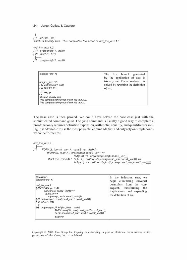
244 Jorge, Gulías, & Cabrero
Copyright © 2007, Idea Group Inc. Copying or distributing in print or electronic forms without writtenpermission of Idea Group Inc. is prohibited.
|——[1] leA(a!1, b!1)which is trivially true. This completes the proof of ord_ins_aux.1.1.
ord_ins_aux.1.2 : [-1] ord(cons(a!1, null))[-2] leA(a!1, b!1) |——[1] ord(cons(b!1, null))
(expand "ord" +) ord_ins_aux.1.2 : [-1] ord(cons(a!1, null)) [-2] leA(a!1, b!1) |---- [1] TRUE
The first branch generated by the application of split is trivially true. The second one is solved by rewriting the definition of ord.
which is trivially true. This completes the proof of ord_ins_aux.1.2. This completes the proof of ord_ins_aux.1.
The base case is then proved. We could have solved the base case just with thesophisticated command grind. The grind command is usually a good way to complete aproof that only requires definition expansion, arithmetic, equality, and quantifier reason-ing. It is advisable to use the most powerful commands first and only rely on simpler oneswhen the former fail.
ord_ins_aux.2 : |——[1] FORALL (cons1_var: A, cons2_var: list[A]): (FORALL (a,b: A): ord(cons(a,cons2_var)) => leA(a,b) => ord(cons(a,ins(b,cons2_var)))) IMPLIES (FORALL (a,b: A): ord(cons(a,cons(cons1_var,cons2_var))) => leA(a,b) => ord(cons(a,ins(b,cons(cons1_var,cons2_var)))))
(skosimp*) (expand "ins" +) ord_ins_aux.2 : [-1] FORALL (a, b: A): ord(cons(a, cons2_var!1)) => leA(a, b) => ord(cons(a, ins(b, cons2_var!1))) [-2] ord(cons(a!1, cons(cons1_var!1, cons2_var!1))) [-3] leA(a!1, b!1) |---- [1] ord(cons(a!1,IF leA(b!1,cons1_var!1) THEN cons(b!1,cons(cons1_var!1,cons2_var!1)) ELSE cons(cons1_var!1,ins(b!1,cons2_var!1)) ENDIF))
In the induction step, we begin eliminating universal quantifiers from the con-sequent, transforming the implications, and expanding the definition of ins.

Certifying Properties of Programs Using Theorem Provers 245
Copyright © 2007, Idea Group Inc. Copying or distributing in print or electronic forms without writtenpermission of Idea Group Inc. is prohibited.
(lift-if) Lifting IF-conditions to the top level, this simplifies to: ord_ins_aux.2 : . . . |---- [1] IF leA(b!1, cons1_var!1) THEN ord(cons(a!1, cons(b!1, cons(cons1_var!1, cons2_var!1)))) ELSE ord(cons(a!1, cons(cons1_var!1, ins(b!1, cons2_var!1)))) ENDIF
As the if-then-else structure in the consequent is not at the outermost level, we issue a lift-if command. It is used to bring the case analysis in an expanded definition to the top level of the sequent where it can be propositionally simplified.
(split 1) Splitting conjunctions, this yields 2 subgoals: ord_ins_aux.2.1 : . . . |---- [1] leA(b!1, cons1_var!1) IMPLIES ord(cons(a!1, cons(b!1, cons(cons1_var!1, cons2_var!1))))
With split, case analyses in the current subgoal are performed. As the consequent is of the form if x then y else z, the goal is splitted into two subgoals: x ⇒ y and ¬x ⇒ z.
(flatten) (expand "ord" +) ord_ins_aux.2.1 : . . . |----
In the first subgoal, the implication is broken and the definition of ord expanded.
[1] leA(a!1, b!1) AND ord(cons(b!1, cons(cons1_var!1, cons2_var!1)))

246 Jorge, Gulías, & Cabrero
Copyright © 2007, Idea Group Inc. Copying or distributing in print or electronic forms without writtenpermission of Idea Group Inc. is prohibited.
(split) (expand "ord" +) (split) ord_ins_aux.2.1.2.2 : . . . [-3] ord(cons(a!1, cons(cons1_var!1, cons2_var!1))) [-4] leA(a!1, b!1) |---- [1] ord(cons(cons1_var!1, cons2_var!1))
We continue the proof combining the commands split and expand.
(expand "ord" -3) ord_ins_aux.2.1.2.2 : . . . [-3] leA(a!1, cons1_var!1) AND ord(cons(cons1_var!1, cons2_var!1)) [-4] leA(a!1, b!1) |---- [1] ord(cons(cons1_var!1, cons2_var!1))
The current subgoal can be solved expanding the definition of ord in the antecedent -3.
(flatten -3) This completes the proof of ord_ins_aux.2.1.2.2. This completes the proof of ord_ins_aux.2.1.2. This completes the proof of ord_ins_aux.2.1.
Now the application of flatten to the antecedent -3 completes the proof of this branch.
ord_ins_aux.2.2 :[-1] FORALL (a, b: A): ord(cons(a, cons2_var!1)) => leA(a, b) => ord(cons(a, ins(b, cons2_var!1)))[-2] ord(cons(a!1, cons(cons1_var!1, cons2_var!1)))[-3] leA(a!1, b!1) |——[1] NOT leA(b!1, cons1_var!1) IMPLIES ord(cons(a!1, cons(cons1_var!1, ins(b!1, cons2_var!1))))

Certifying Properties of Programs Using Theorem Provers 247
Copyright © 2007, Idea Group Inc. Copying or distributing in print or electronic forms without writtenpermission of Idea Group Inc. is prohibited.
At this point, the second alternative of the case analysis is reached. As in the first one, the implicationis broken and the definition of ord expanded. It should be noted that flatten transforms an antecedent¬x into the consequent x, and it transforms a consequent ¬x into the antecedent x.
(flatten)(expand “ord” 2) . . . |——[1] leA(b!1, cons1_var!1)[2] leA(a!1, cons1_var!1) AND ord(cons(cons1_var!1, ins(b!1, cons2_var!1)))
(split 2) (expand "ord" -2) (flatten -2) [-1] FORALL (a, b: A): ord(cons(a, cons2_var!1)) => leA(a, b) => ord(cons(a, ins(b, cons2_var!1))) [-2] ord(cons(a!1, cons(cons1_var!1, cons2_var!1))) [-3] leA(a!1, b!1) |---- [1] ord(cons(cons1_var!1, ins(b!1, cons2_var!1))) [2] leA(b!1, cons1_var!1)
We split the second consequent yielding two subgoals. The first one, leA(a!1, cons1_var!1), is proved by replacing ord in the antecedent -2 with its definition.
(rewrite -1 1) Rewriting using -1, matching in 1, this yields 2 subgoals: ord_ins_aux.2.2.2.1 : . . . |---- [1] leA(cons1_var!1,b!1) [2] ord(cons(cons1_var!1, ins(b!1,cons2_var!1))) [3] leA(b!1,cons1_var!1)
The current goal can be obtained from the inductive hypothesis (the antecedent -1). The command rewrite tries to automatically determine the required substitutions by matching a sequent against expressions in a formula, for example, rewrite -1 1 finds and rewrites an instance of the antecedent -1 throughout the consequent 1. With rewrite, it is also possible to rewrite instances of previously checked proofs.
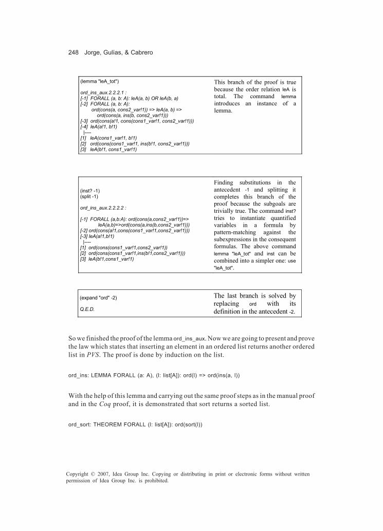
248 Jorge, Gulías, & Cabrero
Copyright © 2007, Idea Group Inc. Copying or distributing in print or electronic forms without writtenpermission of Idea Group Inc. is prohibited.
(lemma "leA_tot") ord_ins_aux.2.2.2.1 : [-1] FORALL (a, b: A): leA(a, b) OR leA(b, a) [-2] FORALL (a, b: A): ord(cons(a, cons2_var!1)) => leA(a, b) => ord(cons(a, ins(b, cons2_var!1))) [-3] ord(cons(a!1, cons(cons1_var!1, cons2_var!1))) [-4] leA(a!1, b!1) |---- [1] leA(cons1_var!1, b!1) [2] ord(cons(cons1_var!1, ins(b!1, cons2_var!1))) [3] leA(b!1, cons1_var!1)
This branch of the proof is true because the order relation leA is total. The command lemma introduces an instance of a lemma.
(inst? -1) (split -1) ord_ins_aux.2.2.2.2 : [-1] FORALL (a,b:A): ord(cons(a,cons2_var!1))=> leA(a,b)=>ord(cons(a,ins(b,cons2_var!1))) [-2] ord(cons(a!1,cons(cons1_var!1,cons2_var!1))) [-3] leA(a!1,b!1) |---- [1] ord(cons(cons1_var!1,cons2_var!1)) [2] ord(cons(cons1_var!1,ins(b!1,cons2_var!1))) [3] leA(b!1,cons1_var!1)
Finding substitutions in the antecedent -1 and splitting it completes this branch of the proof because the subgoals are trivially true. The command inst? tries to instantiate quantified variables in a formula by pattern-matching against the subexpressions in the consequent formulas. The above command lemma "leA_tot" and inst can be combined into a simpler one: use "leA_tot".
(expand "ord" -2) Q.E.D.
The last branch is solved by replacing ord with its definition in the antecedent -2.
So we finished the proof of the lemma ord_ins_aux. Now we are going to present and provethe law which states that inserting an element in an ordered list returns another orderedlist in PVS. The proof is done by induction on the list.
ord_ins: LEMMA FORALL (a: A), (l: list[A]): ord(l) => ord(ins(a, l))
With the help of this lemma and carrying out the same proof steps as in the manual proofand in the Coq proof, it is demonstrated that sort returns a sorted list.
ord_sort: THEOREM FORALL (l: list[A]): ord(sort(l))

Certifying Properties of Programs Using Theorem Provers 249
Copyright © 2007, Idea Group Inc. Copying or distributing in print or electronic forms without writtenpermission of Idea Group Inc. is prohibited.
Figures 3(a) and 3(b) show the proof trees for ord_ins and ord_sort, respectively.
The Result of sort is a Permutation of Elements
Coq As a first step we prove auxiliary laws count_cons and count_cons_cons. In order todo this, it is only necessary to apply β-reductions and to perform case analyses. Thesystem solves automatically each alternative.
Figure 3. Proof trees in PVS for the laws ord_ins and ord_sort
(b) Proof tree for ord_sort(a) Proof tree for ord_ins
(induct "I")
(skoskimp*)(skoskimp*)
(propax) (propax)
(propax) (propax)
(propax)
(expand "ord" +)
(expand "ins" +) (expand "ins" +)
(split)
(flatten) (flatten)
(rewrite "ord_ins_aux" 2)(expand "ord" +)
(split)
(split -1)
(use "leA_tot")
(induct "I")
(skoskimp*)(expand "sort" +)
(expand "ord" +) (expand "sort" +)
(rewrite "ord_ins" +)(propax)

250 Jorge, Gulías, & Cabrero
Copyright © 2007, Idea Group Inc. Copying or distributing in print or electronic forms without writtenpermission of Idea Group Inc. is prohibited.
Lemma count_cons: forall l1 l2: (list A), forall w n: A, (count w l1)=(count w l2) -> (count w (cons n l1))=(count w (cons n l2)).intros. simpl. case (eq_dec w n); auto.Qed.
Lemma count_cons_cons: forall l: (list A), forall n m w: A, (count w (cons n (cons m l)))=(count w (cons m (cons n l))).intros. simpl. case (eq_dec w m); case (eq_dec w n); auto.Qed.
Now, we prove lemma 4 which states that each element appears the same number of timesin ins n l as in n::l. The proof is carried out by induction in l. The base case is automaticallysolved by means of β-reductions.
Lemma count_ins: forall l: (list A), forall n w: A, (count w (ins n l))=(count w (cons n l)).induction l.intros. simpl. auto.
1 subgoal A : Set eq_dec : forall a b : A, a = b + a <> b leA : A -> A -> Prop leA_refl : forall a : A, leA a a leA_trans : forall a b c : A, leA a b -> leA b c -> leA a c leA_antisym : forall a b : A, leA a b -> leA b a -> a = b leA_tot : forall a b : A, leA a b leA b a leA_dec : forall a b : A, {leA a b} + {~ leA a b} a : A l : list A IHl : forall n w : A, count w (ins n l) = count w (n :: l) ============================ forall n w : A, count w (ins n (a :: l)) = count w (n :: a :: l)
In the inductive step, universal quantifiers are moved into the hypothesis environmentand the definition of ins is expanded.
intros. simpl ins.
1 subgoal . . . ============================ count w (if leA_dec n a then n :: a :: l else a :: ins n l) = count w (n :: a :: l)

Certifying Properties of Programs Using Theorem Provers 251
Copyright © 2007, Idea Group Inc. Copying or distributing in print or electronic forms without writtenpermission of Idea Group Inc. is prohibited.
A case analysis is carried out. The first subcase becomes trivial. The second one is solvedusing previous auxiliary laws and the induction hypothesis.
case (leA_dec n a); intros Hle. auto.rewrite count_cons_cons.apply count_cons.apply IHl.Qed.
Finally, by means of this result, it is proved that the number of occurrences of any elementis the same in the sort argument as in its return value.
Lemma count_sort: forall l: (list A), forall w: A, (count w l)=(count w (sort l)).induction l.simpl; auto.intros. simpl sort.rewrite count_ins.apply count_cons. apply IHl.Qed.
Thus, this is the end of the formalization in Coq, which states that the insertion sortalgorithm interchanges the order of the elements in the argument list.
PVS Regarding the previously defined function count, the MEASURE clause indicates thatthe list decreases through recursive calls. The type-correctness condition generated byPVS is proved automatically by the system. In the PVS theory, we demonstrate exactlythe same laws as we have done in the Coq system. Next, the declarations can be seen.
count_cons: LEMMA FORALL (l1, l2: list[A]), (w, n: A): count(w, l1) = count(w, l2) => count(w, cons(n, l1)) = count(w, cons(n, l2))
count_cons_cons: LEMMA FORALL (l: list[A]), (n, m, w: A): count(w, cons(n, cons(m, l))) = count(w, cons(m, cons(n, l)))
These two auxiliary laws are directly solved with the powerful command grind that triesskolemization, instantiation, and if-lifting repeatedly. Figure 4 shows the proof trees ofthe remaining two laws.

252 Jorge, Gulías, & Cabrero
Copyright © 2007, Idea Group Inc. Copying or distributing in print or electronic forms without writtenpermission of Idea Group Inc. is prohibited.
count_ins: LEMMA FORALL (l: list[A]), (n, w: A): count(w, ins(n, l)) = count(w, cons(n, l))
count_sort: THEOREM FORALL (l: list[A]), (w: A): count(w, l) = count(w, sort(l))
(a) Proof tree for count_ins (b) Proof tree for count_sort
Figure 4. Proof trees of the lemma count_ins and the theorem count_sort in PVS
(Induct "I")
(skoskimp*)(skoskimp*)
(expand "ins") (expand "ins" +)
(propax)
(propax)
(lift-if)
(split)
(flatten)
(rewrite "count_cons_cons" +)
(rewrite "count_cons" 2)
(rewrite-with-fnum -1 1)
(Induct "I")
(skoskimp*) (skoskimp*)
(expand "sort" +) (expand "sort" +)
(rewrite "count_ins" +)
(rewrite "count_cons" +)
(rewrite -1 1)
(propax)

Certifying Properties of Programs Using Theorem Provers 253
Copyright © 2007, Idea Group Inc. Copying or distributing in print or electronic forms without writtenpermission of Idea Group Inc. is prohibited.
A Case Study
In this section, we present the verification of part of a real-world application, theimplementation of a distributed video-on-demand server (Gulías, Barreiro, & Freire, 2005)that has been developed in the concurrent functional language Erlang (Armstrong et al.,1996). As the application of a formal method to a large system is extremely difficult or evenimpossible, we apply the techniques presented in Jorge (2004) to verify relevant prop-erties of a part of this system separately, so that when, later, we combine other partialresults, conclusions on the whole system could be drawn.
An Overview of the VoDKA Server
A video-on-demand server is a system that provides video services to several clientssimultaneously. A user can request a particular video at any time, with no pre-establishedtemporal constraints. A video-on-demand server is a quite complex distributed systemthat must satisfy some critical requirements, including large storage capacity, manyconcurrent users, high bandwidth, reliability, scalability, adaptability to the underlyingtopology, and low cost.VoDKA (video-on-demand kernel architecture, http://vodka.lfcia.org) is a project de-voted to providing broadband-quality video-on-demand services to cable clients.Clusters built from cheap off-the-shelf components are proposed as an affordablesolution for the huge demand of resources of the system. However, the main problem ishow to design and implement the distributed application to control the cluster, achievingthe demanding requirements of a video-on-demand system (e.g., scalability, adaptability,availability, flexibility). As a first approach, cluster resources were organized as ahierarchical storage system, identifying three different layers: (a) repository level, tostore all the available media; (b) cache level, in charge of storing videos read from therepository level, before being streamed; and (c) streaming level, a frontend in charge ofprotocol adaption and media streaming to the final client.
The Problem: Cache Block Allocation
The cache layer provides a large aggregate throughput that alleviates usual deficiencies(in terms of bandwidth and concurrency) of the repository level. It is composed by a setof physical nodes each running agents and modules implementing different algorithmsand policies — some quite tricky and error prone. The piece of software to be verifiedin this example is (a simplification of) part of the cache subsystem: the block allocationalgorithm. Other formal techniques have been also applied to other subsystems (Arts &Sánchez, 2002; Gulías, Valderruten, & Abalde, 2003).The local disk of each node of the cache level acts as a local cache, divided into fixed-size blocks (e.g., 8 MB), which store fragments of a media object. In order to attend arequest, media object is firstly looked up in local caches, avoiding the access to therepository layer if possible.

254 Jorge, Gulías, & Cabrero
Copyright © 2007, Idea Group Inc. Copying or distributing in print or electronic forms without writtenpermission of Idea Group Inc. is prohibited.
If a media object must be fetched to cache (because of a cache miss), enough space mustbe booked to load the object from the storage. In order to release some blocks, we haveto assure that these blocks are not in use by other pending tasks, either readings fromcache to the streaming level or fetchings from repository to cache. As locality in cacheis important for performance, blocks of the same media object are in close proximity andwe can speak of block intervals.
Representing Block Intervals
A block interval is modeled as a triple (a,b,x): the interval between blocks a and b(inclusive) has x pending tasks. To store the whole sequence of block intervals, a list isused as shown:
[(a1,b1,x1), (a2,b2,x2), ..., (an,bn,xn)]
For the sake of efficiency, intervals are kept sorted ∀i, ai ≤ bi ∧ bi < ai+1. Moreover, spaceis saved if the sequence is kept compact, that is, ∀i, xi ≠ 0, and (xi ≠ xi+1) ∨ ((xi = xi+1) ∧ (bi+1< ai+1))Several definitions are needed before translating algorithms on blocks, intervals, andsequences into a model. We show both Coq and PVS approaches to highlight differencesbetween provers.
Coq A block interval is defined as a triple of natural numbers including the initial andfinal block and the number of pending requests requiring the interval. Interval is aninductive definition with one constructor, tuple.
Inductive interval: Set:= tuple: nat -> nat -> nat -> interval.
A sequence is then represented as a list of blocks using an inductive type. ConstructorNil represents an empty sequence while Cons represents a sequence constructed froman interval and a sequence.
Inductive seq: Set:= Nil: seq | Cons: interval -> seq -> seq.
Intervals are kept sorted in ascending order, that is, for every sequence [(a1,b1,x1),(a2,b2,x2), ..., (an,bn,xn)], the predicate ∀i, ai ≤ bi ∧ bi < ai+1 holds.
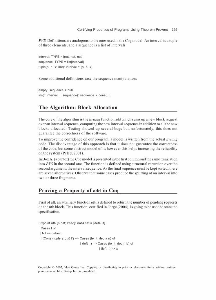
Certifying Properties of Programs Using Theorem Provers 255
Copyright © 2007, Idea Group Inc. Copying or distributing in print or electronic forms without writtenpermission of Idea Group Inc. is prohibited.
PVS Definitions are analogous to the ones used in the Coq model: An interval is a tupleof three elements, and a sequence is a list of intervals.
interval: TYPE = [nat, nat, nat]sequence: TYPE = list[interval]tuple(a, b, x: nat): interval = (a, b, x)
Some additional definitions ease the sequence manipulation:
empty: sequence = nullins(i: interval, l: sequence): sequence = cons(i, l)
The Algorithm: Block Allocation
The core of the algorithm is the Erlang function add which sums up a new block requestover an interval sequence, computing the new interval sequence in addition to all the newblocks allocated. Testing showed up several bugs but, unfortunately, this does notguarantee the correctness of the software.To improve the confidence on our program, a model is written from the actual Erlangcode. The disadvantage of this approach is that it does not guarantee the correctnessof the code, but some abstract model of it; however this helps increasing the reliabilityon the system (Peled, 2001).In Box A, (a part of) the Coq model is presented in the first column and the same translationinto PVS in the second one. The function is defined using structural recursion over thesecond argument: the interval sequence. As the final sequence must be kept sorted, thereare seven alternatives. Observe that some cases produce the splitting of an interval intotwo or three fragments.
Proving a Property of add in Coq
First of all, an auxiliary function nth is defined to return the number of pending requestson the nth block. This function, certified in Jorge (2004), is going to be used to state thespecification.
Fixpoint nth [n:nat; l:seq]: nat->nat:= [default] Cases l of | Nil => default | (Cons (tuple a b x) l’) => Cases (le_lt_dec a n) of
| (left _) => Cases (le_lt_dec n b) of | (left _) => x

256 Jorge, Gulías, & Cabrero
Copyright © 2007, Idea Group Inc. Copying or distributing in print or electronic forms without writtenpermission of Idea Group Inc. is prohibited.
| (right _) => (nth n l’ default) end
| (right _) => defaultend
end.
Function add must satisfy that, in the resulting interval sequence, the number of requestsover the requested block is incremented by one, while all the other blocks remainunchanged.
nth n (add i 1) 0 =
nth n 1 0 if i ≠ n nth n 1 0 + 1 if i = n
This property is split into two theorems provided that i equals n or not.
Box A.
Fixpoint add [n:nat; l: seq]: seq := Cases l of | Nil => (Cons (tuple n n (S O)) Nil) | (Cons (tuple a b x) l') => Cases (le_lt_dec a n) of | (left _) => Cases (le_lt_dec n b) of | (left _) => Cases (eq_nat_dec a n) of | (left _) => Cases (eq_nat_dec n b) of | (left _) => (Cons (tuple a b (S x)) l') | (right _) => (Cons (tuple a a (S x)) (Cons (tuple (S a) b x) l')) end | (right _) => Cases (eq_nat_dec n b) of | (left _) => (Cons (tuple a (pred b) x) (Cons (tuple b b (S x)) l')) | (right _) => (Cons (tuple a (pred n) x) (Cons (tuple n n (S x)) (Cons (tuple (S n) b x) l'))) end end | (right _) => (Cons (tuple a b x) (add n l')) end | (right _) => (Cons (tuple n n (S O)) l) end end.
aC
l)
add(n: nat, l: seq): RECURSIVE seq = CASES l OF null: make(tuple(n,n,1), null), cons(i, l1): IF i`1 <= n THEN IF n <= i`2 THEN IF i`1 = n THEN IF n = i`2 THEN make(tuple(i`1,i`2,i`3+1), l1) ELSE make(tuple(i`1,i`1,i`3+1), make(tuple(i`1+1,i`2,i`3), l1)) ENDIF ELSE IF n = i`2 THEN make(tuple(i`1,i`2-1,i`3), make(tuple(i`2,i`2,i`3+1), l1)) ELSE make(tuple(i`1,n-1,i`3), make(tuple(n,n,i`3+1), make(tuple(n+1,i`2,i`3), l1))) ENDIF ENDIF ELSE make(i, add(n, l1)) ENDIF ELSE make(tuple(n,n,1), l) ENDIF ENDCASES MEASURE length(l)
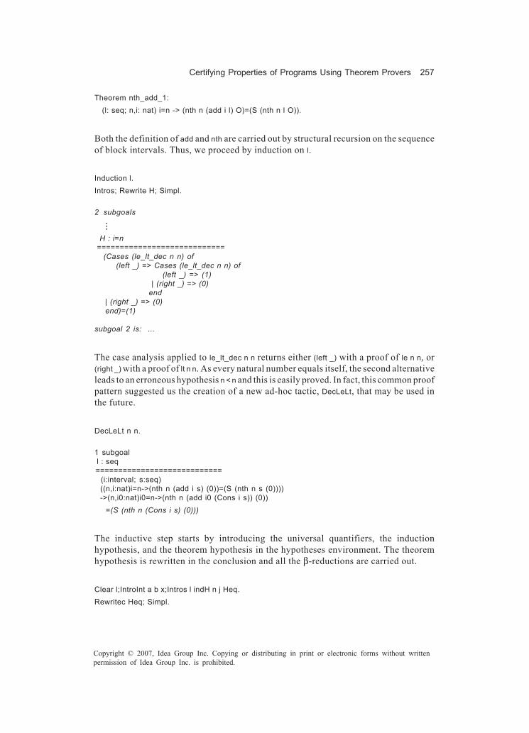
Certifying Properties of Programs Using Theorem Provers 257
Copyright © 2007, Idea Group Inc. Copying or distributing in print or electronic forms without writtenpermission of Idea Group Inc. is prohibited.
Theorem nth_add_1: (l: seq; n,i: nat) i=n -> (nth n (add i l) O)=(S (nth n l O)).
Both the definition of add and nth are carried out by structural recursion on the sequenceof block intervals. Thus, we proceed by induction on l.
Induction l.Intros; Rewrite H; Simpl.
2 subgoals
...
H : i=n ============================ (Cases (le_lt_dec n n) of (left _) => Cases (le_lt_dec n n) of
(left _) => (1) | (right _) => (0)
end | (right _) => (0) end)=(1)
subgoal 2 is: ...
The case analysis applied to le_lt_dec n n returns either (left _) with a proof of le n n, or(right _) with a proof of lt n n. As every natural number equals itself, the second alternativeleads to an erroneous hypothesis n < n and this is easily proved. In fact, this common proofpattern suggested us the creation of a new ad-hoc tactic, DecLeLt, that may be used inthe future.
DecLeLt n n.
1 subgoal l : seq ============================ (i:interval; s:seq) ((n,i:nat)i=n->(nth n (add i s) (0))=(S (nth n s (0)))) ->(n,i0:nat)i0=n->(nth n (add i0 (Cons i s)) (0)) =(S (nth n (Cons i s) (0)))
The inductive step starts by introducing the universal quantifiers, the inductionhypothesis, and the theorem hypothesis in the hypotheses environment. The theoremhypothesis is rewritten in the conclusion and all the β-reductions are carried out.
Clear l;IntroInt a b x;Intros l indH n j Heq.Rewritec Heq; Simpl.
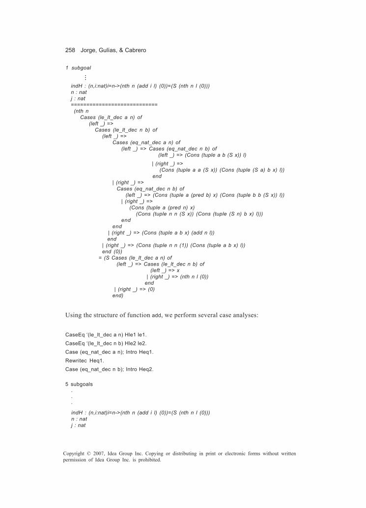
258 Jorge, Gulías, & Cabrero
Copyright © 2007, Idea Group Inc. Copying or distributing in print or electronic forms without writtenpermission of Idea Group Inc. is prohibited.
1 subgoal
...
indH : (n,i:nat)i=n->(nth n (add i l) (0))=(S (nth n l (0))) n : nat j : nat ============================ (nth n Cases (le_lt_dec a n) of (left _) => Cases (le_lt_dec n b) of (left _) => Cases (eq_nat_dec a n) of (left _) => Cases (eq_nat_dec n b) of (left _) => (Cons (tuple a b (S x)) l) | (right _) => (Cons (tuple a a (S x)) (Cons (tuple (S a) b x) l)) end | (right _) => Cases (eq_nat_dec n b) of (left _) => (Cons (tuple a (pred b) x) (Cons (tuple b b (S x)) l)) | (right _) => (Cons (tuple a (pred n) x) (Cons (tuple n n (S x)) (Cons (tuple (S n) b x) l))) end end | (right _) => (Cons (tuple a b x) (add n l)) end | (right _) => (Cons (tuple n n (1)) (Cons (tuple a b x) l)) end (0)) = (S Cases (le_lt_dec a n) of (left _) => Cases (le_lt_dec n b) of (left _) => x | (right _) => (nth n l (0)) end | (right _) => (0) end)
Using the structure of function add, we perform several case analyses:
CaseEq ‘(le_lt_dec a n) Hle1 le1.CaseEq ‘(le_lt_dec n b) Hle2 le2.Case (eq_nat_dec a n); Intro Heq1.Rewritec Heq1.Case (eq_nat_dec n b); Intro Heq2.
5 subgoals
. . . ====== indH : (n,i:nat)i=n->(nth n (add i l) (0))=(S (nth n l (0))) n : nat j : nat

Certifying Properties of Programs Using Theorem Provers 259
Copyright © 2007, Idea Group Inc. Copying or distributing in print or electronic forms without writtenpermission of Idea Group Inc. is prohibited.
Hle1 : (le a n) le1 : (le_lt_dec a n)=(left (le a n) (lt n a) Hle1) Hle2 : (le n b) le2 : (le_lt_dec n b)=(left (le n b) (lt b n) Hle2) Heq2 : n=b ============================ (nth n (Cons (tuple n b (S x)) l) (0))=(S x)
subgoal 2 is: ...
The first alternative is easily proved replacing b with n, doing all β-reductions and thenapplying the defined tactic DecLeLt.
RewritecL Heq2. Simpl. DecLeLt n n.4 subgoals
. . . ======
indH : (n,i:nat)i=n->(nth n (add i l) (0))=(S (nth n l (0))) n : nat j : nat Hle1 : (le a n) le1 : (le_lt_dec a n)=(left (le a n) (lt n a) Hle1) Hle2 : (le n b) le2 : (le_lt_dec n b)=(left (le n b) (lt b n) Hle2) Heq2 : ~n=b ============================ (nth n (Cons (tuple n n (S x)) (Cons (tuple (S n) b x) l)) (0))=(S x)
subgoal 2 is: ...
The rest of alternatives but one are solved similarly. The remaining one requires theinduction hypothesis.
Simpl. DecLeLt n n.Case (eq_nat_dec n b); Intro Heq2.RewritecL Heq2. Simpl. Rewrite le1.DecLeLt n ‘(pred n). DecLeLt n n.Simpl. Rewrite le1.DecLeLt n n. DecLeLt n ‘(pred n).Simpl. Rewrite le1. Rewrite le2.Apply indH; Auto.Simpl. DecLeLt n n.Qed.

260 Jorge, Gulías, & Cabrero
Copyright © 2007, Idea Group Inc. Copying or distributing in print or electronic forms without writtenpermission of Idea Group Inc. is prohibited.
The second theorem to be proved is quite similar (though larger):
Theorem nth_add_2: (l:seq; n, i:nat) ~i=n->(nth n (add i l) O)=(nth n l O).
Proving a Property of add in PVS
As done in Coq, we define an auxiliary function nth to state the specification:
nth(n: nat, l: sequence, default: nat): RECURSIVE nat = CASES l OF null: default,
cons(i, l1): IF i‘1 <= n THEN IF n <= i‘2 THEN i‘3 ELSE nth(n, l1, default) ENDIF ELSE default
ENDIF ENDCASES MEASURE length(l)
The resulting theorems are stated as:
nth_add_1: THEOREM FORALL (m, n: nat), (l: sequence): m = n => nth(n, add(m, l), 0) = 1 + nth(n, l, 0)
nth_add_2: THEOREM FORALL (m, n: nat), (l: sequence): NOT (m = n) => nth(n, add(m, l), 0) = nth(n, l, 0)
In this case, PVS proofs are carried out by the system automagically using the advancedcommand induct-and-simplify. A great deal of work is carried out by PVS if compared withCoq version.
Assuring the Canonical Form of Interval Sequences
The representation of interval sequences should be canonical (in the sense that twodifferent representations always correspond to two different objects) to achieve betterspace and time behaviour. Theorem provers can help us to assure that sequences arealways delivered in canonical form. We should demonstrate that the application of addto an interval sequence in canonical form always delivers a new canonical sequence.First, we present the property that states that intervals in a sequence are in ascendingorder. The predicate ascend asserts whether a sequence [(a1,b1,x1), ..., (an,bn,xn)] is sorted
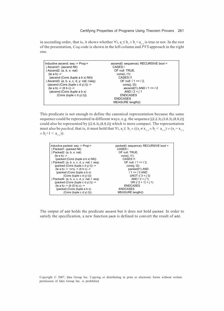
Certifying Properties of Programs Using Theorem Provers 261
Copyright © 2007, Idea Group Inc. Copying or distributing in print or electronic forms without writtenpermission of Idea Group Inc. is prohibited.
in ascending order, that is, it shows whether ∀i, ai ≤ bi ∧ bi < ai+1 is true or not. In the restof the presentation, Coq code is shown in the left column and PVS approach in the rightone.
Inductive ascend: seq -> Prop:= | Ascend1: (ascend Nil) | Ascend2: (a, b, x: nat) (le a b) -> (ascend (Cons (tuple a b x) Nil)) | Ascend3: (a, b, x, c, d, y: nat; l:seq) (ascend (Cons (tuple c d y) l)) -> (le a b) -> (lt b c) -> (ascend (Cons (tuple a b x) (Cons (tuple c d y) l))).
ascend(l: sequence): RECURSIVE bool = CASES l OF null: TRUE, cons(i, l1): CASES l1 OF null: i`1 <= i`2, cons(j, l2): ascend(l1) AND i`1 <= i`2 AND i`2 < j`1 ENDCASES ENDCASES MEASURE length(l)
This predicate is not enough to define the canonical representation because the samesequence could be represented in different ways, e.g. the sequence [(2,2,3),(3,6,3),(8,9,2)]could also be represented by [(2,6,3),(8,9,2)] which is more compact. The representationmust also be packed, that is, it must hold that ∀i, ai ≤ bi ∧ ((xi ≠ xi+1 ∧ bi < ai+1) ∨ (xi = xi+1∧ bi+1 < ai+1)).
Inductive packed: seq -> Prop:= | Packed1: (packed Nil) | Packed2: (a, b, x: nat) (le a b) -> (packed (Cons (tuple a b x) Nil)) | Packed3: (a, b, x, c, d, y: nat; l: seq) (packed (Cons (tuple c d y) l)) -> (le a b) -> ~x=y -> (lt b c) -> (packed (Cons (tuple a b x) (Cons (tuple c d y) l))) | Packed4: (a, b, x, c, d, y: nat; l: seq) (packed (Cons (tuple c d y) l)) -> (le a b) -> (lt (S b) c) -> (packed (Cons (tuple a b x) (Cons (tuple c d y) l))).
packed(l: sequence): RECURSIVE bool = CASES l OF null: TRUE, cons(i, l1): CASES l1 OF null: i`1 <= i`2, cons(j, l2): packed(l1) AND i`1 <= i`2 AND ((NOT (i`3 = j`3) AND i`2 < j`1) OR (i`2 + 1) < j`1) ENDCASES ENDCASES MEASURE length(l)
The output of add holds the predicate ascend but it does not hold packed. In order tosatisfy the specification, a new function pack is defined to convert the result of add.

262 Jorge, Gulías, & Cabrero
Copyright © 2007, Idea Group Inc. Copying or distributing in print or electronic forms without writtenpermission of Idea Group Inc. is prohibited.
Fixpoint packAux [i:interval;l:seq]:seq :=Cases i of | (tuple a b x) => Cases l of | Nil => (Cons (tuple a b x) Nil) | (Cons (tuple c d y) l') => Cases (eq_nat_dec x y) of | (left _) => Cases (eq_nat_dec (S b) c) of | (left _) => (packAux (tuple a d x) l') | (right _) => (Cons (tuple a b x) (packAux (tuple c d y) l')) end | (right _) => (Cons (tuple a b x) (packAux (tuple c d y) l')) end end end. Definition pack [l: seq]: seq:= Cases l of Nil => Nil | (Cons i l') => (packAux i l') end.
packAux(i: interval, l: sequence): RECURSIVE sequence = CASES l OF null: ins(i, empty), cons(i1, l1): IF i`3 = i1`3 THEN IF i`2 + 1 = i1`2 THEN packAux(tuple(i`1,i1`2,i`3),l1) ELSE ins(i, packAux(i1, l1)) ENDIF ELSE ins(i, packAux(i1, l1)) ENDIF ENDCASES MEASURE length(l) pack(l: sequence): sequence = CASES l OF null: empty, cons(i, l1): packAux(i, l1) ENDCASES
To complete the canonical representation, we need a predicate that guarantees that everyblock in the sequence has at least one request.
Inductive strictPosit: seq -> Prop:= | StrictPosit1: (strictPosit Nil) | StrictPosit2: (l:seq; a, b, x: nat) (strictPosit l) -> ~x=O -> (strictPosit (Cons (tuple a b x) l)). Inductive canonical: seq -> Prop:= Canonical: (l: seq) (packed l) -> (strictPosit l) -> (canonical l).
strictPosit(l: sequence): RECURSIVE bool = CASES l OF null: TRUE, cons(x, xs): strictPosit(xs) AND x`3>0 ENDCASES MEASURE length(l) canonical(l: sequence): bool = packed(l) AND strictPosit(l)
We should show that pack returns an interval sequence equivalent to the one it gets asargument as long as it is sorted in ascending order.
Lemma nth_pack: (l:sequence;n:nat) (ascend l) -> (nth n l O) = (nth n (pack l) O).
nth_pack: LEMMA FORALL (n: nat), (l: sequence): ascend(l) => nth(n, l, 0) = nth(n, pack(l), 0)
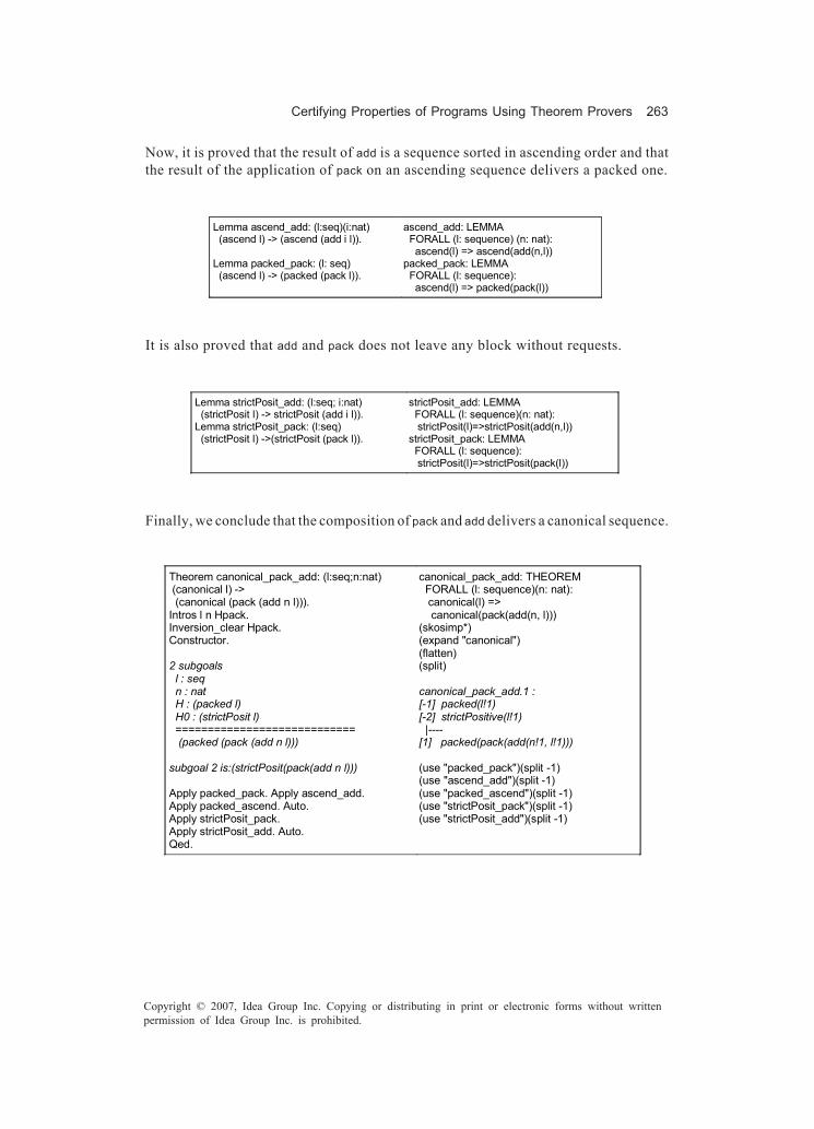
Certifying Properties of Programs Using Theorem Provers 263
Copyright © 2007, Idea Group Inc. Copying or distributing in print or electronic forms without writtenpermission of Idea Group Inc. is prohibited.
Now, it is proved that the result of add is a sequence sorted in ascending order and thatthe result of the application of pack on an ascending sequence delivers a packed one.
Lemma ascend_add: (l:seq)(i:nat) (ascend l) -> (ascend (add i l)). Lemma packed_pack: (l: seq) (ascend l) -> (packed (pack l)).
ascend_add: LEMMA FORALL (l: sequence) (n: nat): ascend(l) => ascend(add(n,l)) packed_pack: LEMMA FORALL (l: sequence): ascend(l) => packed(pack(l))
It is also proved that add and pack does not leave any block without requests.
Lemma strictPosit_add: (l:seq; i:nat) (strictPosit l) -> strictPosit (add i l)). Lemma strictPosit_pack: (l:seq) (strictPosit l) ->(strictPosit (pack l)).
strictPosit_add: LEMMA FORALL (l: sequence)(n: nat): strictPosit(l)=>strictPosit(add(n,l)) strictPosit_pack: LEMMA FORALL (l: sequence): strictPosit(l)=>strictPosit(pack(l))
Finally, we conclude that the composition of pack and add delivers a canonical sequence.
Theorem canonical_pack_add: (l:seq;n:nat) (canonical l) -> (canonical (pack (add n l))). Intros l n Hpack. Inversion_clear Hpack. Constructor. 2 subgoals l : seq n : nat H : (packed l) H0 : (strictPosit l) ============================ (packed (pack (add n l))) subgoal 2 is:(strictPosit(pack(add n l))) Apply packed_pack. Apply ascend_add. Apply packed_ascend. Auto. Apply strictPosit_pack. Apply strictPosit_add. Auto. Qed.
canonical_pack_add: THEOREM FORALL (l: sequence)(n: nat): canonical(l) => canonical(pack(add(n, l))) (skosimp*) (expand "canonical") (flatten) (split) canonical_pack_add.1 : [-1] packed(l!1) [-2] strictPositive(l!1) |---- [1] packed(pack(add(n!1, l!1))) (use "packed_pack")(split -1) (use "ascend_add")(split -1) (use "packed_ascend")(split -1) (use "strictPosit_pack")(split -1) (use "strictPosit_add")(split -1)

264 Jorge, Gulías, & Cabrero
Copyright © 2007, Idea Group Inc. Copying or distributing in print or electronic forms without writtenpermission of Idea Group Inc. is prohibited.
Table 1(a) presents quantitative information on each Coq theory for this example,showing the number of lines of code, the number of definitions (including new tactics)and the number of laws and the relation between the number of lines and the number oflaws and definitions which can be used as a complexity measure for the theory. Table 1(b)shows the same information on PVS theories, where each provided command for thedevelopment of proofs has been counted as one line of code.
Summary
We present how formal methods, and in particular theorem provers, help to performsoftware verification, assuring that some relevant properties hold in a program. Wesuggest developing programs using side-effect free languages, such as functionallanguages, where tools like equational reasoning make sense and can ease the analysisof programs.In the chapter, proofs of properties have been carried out both in an informal andexhaustive style (on functional programs), and with the help of Coq and PVS proofassistants. In general, the elaboration of proofs is based on the syntactic structure of theprogram. As usual, complexity is managed by dividing the problem in smaller problemsusing auxiliary lemmas and laws. The explored provers have different philosophies: Coqformalizes higher-order logic with inductive types, which gives a rigorous notion of proofand the possibility of extracting automatically functional programs from the algorithmiccontent of the proof. On the other hand, PVS does not have such a rigorous notion ofproof but it incorporates powerful automatic theorem-proving capabilities that reducethe amount of work for the developer.As a first example, we present the pedagogic case study of an insertion sort algorithmover lists of elements. The sorting criteria is defined by some reflexive, antisymmetric,transitive, and total relation. The proving procedure is kept as general as possible.Though the example is simple, the procedure to be accomplished for more complex piecesof software follows the same pattern.
Table 1. Quantitative information of the development
(a) COQ theories
Theory Lines Defs. Laws Prop
SeqDefs 49 4 0 12
SeqLaws 144 9 5 10
SeqCan 601 8 21 20
totals 794 21 26 16
Theory Lines Defs. Laws Prop
SeqDefs 47 7 0 6
SeqLaws 14 0 2 7
SeqCan 323 6 22 11
totals 384 13 24 10
(b) PVS theories

Certifying Properties of Programs Using Theorem Provers 265
Copyright © 2007, Idea Group Inc. Copying or distributing in print or electronic forms without writtenpermission of Idea Group Inc. is prohibited.
As an example of a real-world application, we applied the method to a distributed video-on-demand server developed using a functional language. So far, we have expoundedseparately the formal verification of part of the functionality of the server. Other partialresults would be necessary to reach conclusions on the whole system. The verificationis not done on the real system but on some abstract model of it.Formal methods are not intended to provide absolute reliability, but to increase softwarereliability. Specification and verification yield a better understanding of the program. Acorrectness proof is a detailed explanation of how the program works. Formal methodscan be used to improve the design of systems, its efficiency, and to certify its correctness.It is often difficult to apply formal methods to a whole system, so we should look forcompositional techniques. We think that the future of program verification heads for ageneral proposal: to obtain certified software libraries.
Acknowledgment
This work is partially supported by projects MEC TIN2005-08986 and XUGAPGIT05TIC10503PR.
References
Armstrong, J., Virding, R., Wikström, C., & Williams, M. (1996). Concurrent program-ming in Erlang. Hertfordshire, UK: Prentice Hall.
Arts, T., & Sánchez, J. J. (2002). Global scheduler properties derived from local restric-tions. In ACM SIGPLAN Workshop on Erlang (pp. 49-57). Pittsburgh, PA: ACMPress.
Bérard, B., Bidoit, A. F. M., Laroussine, F., Petit, A., Petrucci, L., Schoenebelen, P., et al.(2001). Systems and software verification. Model-checking techniques and tools.Springer-Verlag.
Bertot, Y., & Casteran, P. (2004). Interactive theorem proving and program develop-ment, Coq’Art: The calculus of inductive constructions. Springer-Verlag.
Bird, R., & Wadler, P. (1988). Introduction to functional programming. Hertfordshire,UK: Prentice Hall.
Clarke, E. M., Grumberg, O., & Peled, D. A. (1999). Model checking. Cambridge, MA: MITPress.
Clarke, E. M., Wing, J. M., Alur, R., Cleaveland, R., Dill, D., Emerson, A., et al. (1996).Formal methods: State of the art and future directions. ACM Computing Surveys,28(4), 626-643.
Coq Development Team, The. (2004). The Coq proof assistant reference manual, version8.0. Rocquencourt, France.

266 Jorge, Gulías, & Cabrero
Copyright © 2007, Idea Group Inc. Copying or distributing in print or electronic forms without writtenpermission of Idea Group Inc. is prohibited.
Crow, J., Owre, S., Rushby, J., Shankar, N., & Srivas, M. (1995). A tutorial introductionto PVS. In Wift ’95 Workshop on Industrial-Strength Formal Specication Tech-niques. Boca Raton, FL: Computer Science Laboratory, SRI International.
Ghezzi, C., Jazayeri, M., & Mandrioli, D. (1991). Fundamentals of software engineering.Englewood Cliffs, NJ: Prentice Hall.
Giménez, E. (1998). A tutorial on recursive types in Coq (Tech. Rep. No. 0221).Rocquencourt, France: INRIA. (for Coq V6.2)
Gordon, M. J., Milner, A. J., & Wadsworth, C. P. (1979). Edinburgh LCF: A mechanisedlogic of computation: Vol. 78. Springer-Verlag.
Gordon, M. J. C., & Melham, T. F. (1993). Introduction to HOL: A theorem provingenvironment for higher order logic. New York: Cambridge University Press.
Gulías, V. M., Barreiro, M., & Freire, J. L. (2005). VODKA: Developing a video-on-demandserver using distributed functional programming. Journal of Functional Program-ming, 15(4).
Gulías, V. M., Valderruten, A., & Abalde, C. (2003). Building functional patterns forimplementing distributed applications. In IFIP/ACM Latin America NetworkingConference: Towards a Latin American Agenda for Network Research (LANC’03)(pp. 89-98). New York: ACM Press.
Gunter, C., & Mitchell, J. (1996). Strategic directions in software engineering andprogramming languages. ACM Computing Surveys, 28(4), 727-737.
Hudak, P. (1989). Conception, evolution, and application of functional programminglanguages. ACM Computing Surveys, 21(3), 359-411.
Huet, G., Kahn, G., & Paulin-Mohring, C. (2002). The Coq proof assistant: A tutorial,version 7.3 (Technical report). INRIA.
Jorge, J. S. (2004). Estudio de la verificación de propiedades de programas funcionales:De las pruebas manuales al uso de asistentes de pruebas. Unpublished doctoraldissertation, University of A Coruña, Spain.
Kaufmann, M., Mannolios, P., & Moore, J. S. (2000a). Computer-aided reasoning: ACL2case studies. Boston: Kluwer Academic Publishers.
Kaufmann, M., Mannolios, P., & Moore, J. S. (2000b). Computer-aided reasoning: Anapproach. Norwell, MA: Kluwer Academic Publishers.
Leroy, X., et al. (2004). The Objective Caml system: Documentation and user’s manual,release 3.08.
Nielson, F., Nielson, H. R., & Hankin, C. (1999). Principles of program analysis. Springer-Verlag.
Owre, S., Rushby, J. M., & Shankar, N. (1992). PVS: A prototype verication system. InThe 11th International Conference on Automated Deduction (Vol. 607, pp. 748-752). New York: Springer-Verlag.
Owre, S., Shankar, N., & Rushby, J. M. (1995). The PVS specification language. MenloPark, CA: Computer Science Laboratory, SRI International.
Paulson, L. C. (1990). Isabelle: The next 700 theorem provers. In P. Odifreddi (Ed.), Logicand computer science (pp. 361-386). London: Academic Press.

Certifying Properties of Programs Using Theorem Provers 267
Copyright © 2007, Idea Group Inc. Copying or distributing in print or electronic forms without writtenpermission of Idea Group Inc. is prohibited.
Paulson, L. C. (1994). Isabelle: A generic theorem prover. New York: Springer-Verlag.Paulson, L. C. (1996). ML for the working programmer (2nd ed.). New York: Cambridge
University Press.Peled, D. A. (2001). Software reliability methods. Berlin; Heidelberg; New York: Springer-
Verlag.Roscoe, A. W. (1994). Model-checking CSP. In A. W. Roscoe (Ed.), A classical mind:
Essays in honour of C. A. R. Hoare (pp. 353-378). Hertfordshire, UK: Prentice-Hall.Weis, P., & Leroy, X. (1999). Le langage Caml (2nd ed.). Paris: Dunod.
268 Martínez López
Copyright © 2007, Idea Group Inc. Copying or distributing in print or electronic forms without writtenpermission of Idea Group Inc. is prohibited.
Chapter XI
Static Type Systems:From Specificationto Implementation
Pablo E. Martínez López,LIFIA, Facultad de Informática, UNLP, Argentina
Abstract
Static type systems are fundamental tools used to determine properties of programsbefore execution. There exist several techniques for validation and verification ofprograms based on typing. Thus, type systems are important to know for the practicioner.When designing and implementing a technique based on typing systems, there is usuallya gap between the formal tools used to specify it, and the actual implementations. Thisgap can be an obstacle for language designers and programmers. A better understandingof the features of a type system and how they are implemented can help enourmouslyto the good design and implementation of new and powerful verification methods basedon type systems. This chapter addresses the problem of specifing and implementing astatic type system for a simple language, but containing many of the subtleties foundin bigger, mainstream languages. This contributes to the understanding of the techniques,thus bridging the gap between theory and practice. Additionally, the chapter containsa small survey of some of the existing developments in the static typing area and thestatic analysis based on typing.
Static Type Systems 269
Copyright © 2007, Idea Group Inc. Copying or distributing in print or electronic forms without writtenpermission of Idea Group Inc. is prohibited.
Introduction
When someone speaks about verification and validation of programs, it is not verycommon that a static type system comes to one’s mind. However, static typing tech-niques have been a foundation for many of the developments in the theory and practiceof this area of computing science.A static type system (Cardelli, 1997; Cardelli & Wegner, 1985; Curry & Feys, 1958;Hindley, 1969; Hindley, 1995; Milner, 1978; Pierce, 2002) is a fundamental tool used todetermine properties of programs before execution — for example, the absence of someexecution errors — and to provide rudimentary documentation when coding solutionsin a programming language. The main motivation for the use of these systems is that everyprogram with a type calculated statically — that is, based only on the text of the programand not on its computation — is free from some kinds of errors during execution. Theclassic motto coined by Robin Milner is “well-typed programs cannot go wrong” (1978).This guarantees a certain correctness of the code and also helps omit specific checks inthe executable code to avoid these kinds of problems, thus obtaining a more efficientprogram.When designing static type systems, a trade-off between expressiveness and decidabilityhas to be made. The computation prescribed by a static type system is limited — it mayhappen that given a type system, a decidable inference algorithm does not exist; it isusually said that the system is not decidable. So, the choices are: Design a decidablesystem discarding some number of correct programs, or design a precise system but witha noncomputable notion of typing. Both alternatives have been thoroughly studied.When choosing the first alternative, the goal is to maximize the expressiveness of thesystem — that is, the number of correct accepted programs be as large as possible, whileminimizing the number of incorrect accepted ones — without losing decidability. In thisline of research appear polymorphic type systems (Damas & Milner, 1982; Jim, 1996;Milner, 1978; Reynolds, 1983) as the one of ML (Clément, Despeyroux, Despeyroux, &Kahn, 1986; Rèmy & Pottier, 2004) or Haskell (Peyton Jones & Hughes, 1999), andsystems with subtypes (Henglein & Rehof, 1997; Mitchell, 1991; Palsberg, Wand, &O’Keefe, 1997), overloading (Jones, 1994a; Jones, 1996; Thatte, 1992), recursive types(Tiuryn & Wand, 1993), records (Gaster & Jones, 1996; Rèmy, 1989), and so on.In the second case, the idea is to design semiautomatic tools to help in the constructionof programs, maximizing the ability to perform automatic type inference. In this line ofresearch appear Girard’s System F (Girard, 1989; Reynolds, 1974), and dependent typesystems as the Type Theory of Martin-Löf (Nordström, Petersson, & Smith, 1990) — onwhich a tool like Alf (Thorsten, Altenkirch, Gaspes, Nordström, & von Sydow, 1994) isbased — and the calculus of constructions (Coquand & Huet, 1988) — on which the Coqproof assistant (Bertot & Castéran, 2004; The Coq proof assistant, 2004) is based.This chapter concentrates on the first of these two choices.Static type systems are an integral part of the definition of a language, similar to thegrammar defining the syntax of programs. Furthermore, just as there is a tool implement-ing the grammar — the parser — there is a tool implementing the type system. It can beeither a type checker, or a type inferencer (the difference between typechecking and type

270 Martínez López
Copyright © 2007, Idea Group Inc. Copying or distributing in print or electronic forms without writtenpermission of Idea Group Inc. is prohibited.
inference will be discussed in subsequent sections). Usually, there is a gap between theformal tools used to specify a type system, and the actual implementations. Once a typesystem has been designed, finding an algorithm for typechecking or type inference maybe from really easy to extremely hard, or even impossible. There are usually twohindrances when implementing type inference: inherent subtleties of the system andtechniques used to improve performance. This gap can be an obstacle for languagedesigners and programmers. A better understanding of the features of a type system, andhow they are implemented can help enourmously to the good design and implementationof new and powerful verification methods based on type systems.Type systems are intrinsically related to the semantics of the language. The mainproperty of a type system is soundness, which states that any typeable program is freeof the errors addressed by the system. However, a purely syntactic treatment of typesis enough for the purpose of this chapter — that is, no formal semantics will be given tothe language, and no proof of soundness for the type system. These issues have beenaddressed in the literature — Reynolds (1998), for example.What this chapter addresses is the problem of specifying and implementing a static typesystem for a simple language, but which contains many of the subtleties found in bigger,mainstream languages. The chapter begins explaining in detail the basic techniques forspecification of the type systems and then discusses a straightforward way to implementit, showing the relationship between the two. This contributes to the understanding ofthe techniques, thus bridging the gap between theory and practice; this contribution mayhelp in the design of other techniques for verification and validation of programs.Continuing with the chapter, a small survey of some of the existing developments in thestatic typing area and the static analysis based on typing are given, such as the additionof records and variant types, recursive and overloaded types, register allocation, sizedtypes, type specialization, and so on, is given. Finally, some conclusions are drawn.
The Basic Language and Its Typing
The development of a formal system — a system used to capture essential features ofthe real world by means of a formal language and deductive mechanisms — always startsby defining the syntax of the languages involved. The language used in this chapter isa very simple one, but has enough constructs to present the more subtle problems oftyping: It has numbers, Booleans, higher-order functions, tuples, and recursion. Afunctional language (Bird, 1998) has been chosen because of its simplicity, allowing foreasy illustration of the features of the type system.Functional programming is a programming paradigm that concentrates on the descrip-tion of values rather than on the sequencing of commands. For that reason, its semanticsis easy, assigning a value to each valid expression. The interesting feature aboutfunctional programming is the existence of a special kind of values, called functions, thatare used to describe the relation between two sets of values and that can also beinterpreted as the prescription of information transformation — that is, a program. Infunctional languages, functions are treated just like any other value, and thus can be
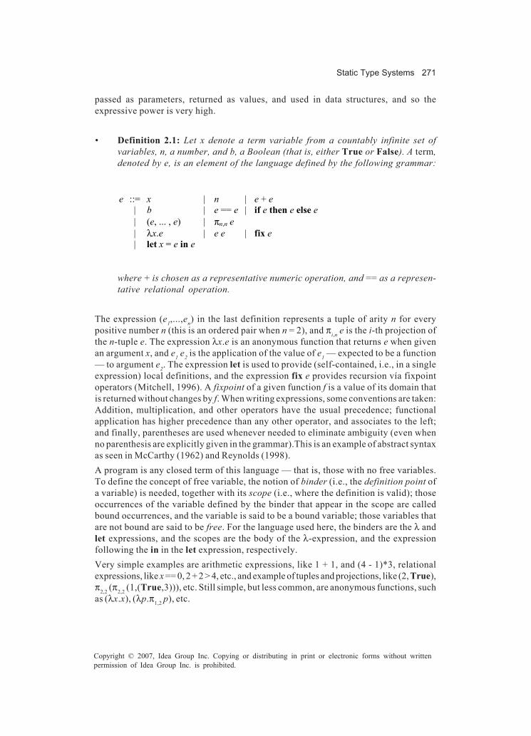
Static Type Systems 271
Copyright © 2007, Idea Group Inc. Copying or distributing in print or electronic forms without writtenpermission of Idea Group Inc. is prohibited.
passed as parameters, returned as values, and used in data structures, and so theexpressive power is very high.
• Definition 2.1: Let x denote a term variable from a countably infinite set ofvariables, n, a number, and b, a Boolean (that is, either True or False). A term,denoted by e, is an element of the language defined by the following grammar:
e ::= x | n | e + e | b | e == e | if e then e else e | (e, ... , e) | πn,n e | λx.e | e e | fix e | let x = e in e
where + is chosen as a representative numeric operation, and == as a represen-tative relational operation.
The expression (e1,...,en) in the last definition represents a tuple of arity n for everypositive number n (this is an ordered pair when n = 2), and πi,n e is the i-th projection ofthe n-tuple e. The expression λx.e is an anonymous function that returns e when givenan argument x, and e1 e2 is the application of the value of e1 — expected to be a function— to argument e2. The expression let is used to provide (self-contained, i.e., in a singleexpression) local definitions, and the expression fix e provides recursion vía fixpointoperators (Mitchell, 1996). A fixpoint of a given function f is a value of its domain thatis returned without changes by f. When writing expressions, some conventions are taken:Addition, multiplication, and other operators have the usual precedence; functionalapplication has higher precedence than any other operator, and associates to the left;and finally, parentheses are used whenever needed to eliminate ambiguity (even whenno parenthesis are explicitly given in the grammar).This is an example of abstract syntaxas seen in McCarthy (1962) and Reynolds (1998).A program is any closed term of this language — that is, those with no free variables.To define the concept of free variable, the notion of binder (i.e., the definition point ofa variable) is needed, together with its scope (i.e., where the definition is valid); thoseoccurrences of the variable defined by the binder that appear in the scope are calledbound occurrences, and the variable is said to be a bound variable; those variables thatare not bound are said to be free. For the language used here, the binders are the λ andlet expressions, and the scopes are the body of the λ-expression, and the expressionfollowing the in in the let expression, respectively.Very simple examples are arithmetic expressions, like 1 + 1, and (4 - 1)*3, relationalexpressions, like x == 0, 2 + 2 > 4, etc., and example of tuples and projections, like (2, True),π2,2 (π2,2 (1,(True,3))), etc. Still simple, but less common, are anonymous functions, suchas (λx.x), (λp.π1,2 p), etc.

272 Martínez López
Copyright © 2007, Idea Group Inc. Copying or distributing in print or electronic forms without writtenpermission of Idea Group Inc. is prohibited.
Growing in complexity, there are examples using local definitions and conditionals:
let fst = λp. π1,2 p in fst (2,5)
and
let max = λx. λy. if x>y then x else y in max 2 5
Finally, recursion is the most involved feature; the factorial is an example of a recursivefunction:
let fact = fix (λf. λv. if v == 0then 1else v * f (v – 1))
in (fact 2, fact 5)
Observe how recursion is expressed using the fix operator. An equivalent way to providethis is to use a construct similar to let, but allowing recursive definitions (typically calledletrec, and assumed implicitly in many languages); it can be defined as syntactic sugar,by using fix in the following way:
letrec f = e in e’ ≡ let f = fix (λf.e) in e’
In this way, the previous example can be rewritten as:
letrec fact = λv. if v == 0then 1else v * fact (v – 1)
in (fact 2, fact 5)
which is a more common way of finding recursion. Had this construct been added insteadof fix, the set of binder expressions would have to be extended with it, and the scope ofthe new binder defined as both expressions appearing in the letrec.A naive approach for ruling out typing errors is using syntactic categories to discriminateexpressions of different types — for example, instead of having a single syntacticcategory e of programs, a naive designer would have defined one category ei for integer

Static Type Systems 273
Copyright © 2007, Idea Group Inc. Copying or distributing in print or electronic forms without writtenpermission of Idea Group Inc. is prohibited.
expressions, one category eb for Boolean expressions, and so on. The main problem isthat the set of typed terms is not context free. This is shown in two ways: First of all, thereare expressions in the language that can take different types — for example, conditionals,or local definitions — and so they have to be replicated on each syntactic category; butsecond, and much more important, there is usually an infinite number of sets of valuesto discriminate, but there cannot be an infinite number of syntactic categories — context-free grammars are finite tools.The specification of the type system is given in two steps: First, all the nonfunctionalparts (that is, numbers, Booleans, and tuples) are presented, and then, functions areadded to the system. The reason is that functions introduce many of the subtleties thatmake the system complex (and interesting).
Typing Nonfunctional Elements
The type system is specified as a relation between an expression and a type, denoted byτ, which is a term of a new language used to classify programs according to the kind ofvalue they may produce when executed (if they terminate). In a naive interpretation, a typecan be identified with a set of values.
• Definition 2.2: A type, denoted by τ, is an element of the language defined by thefollowing grammar:
τ ::= Int | Bool | (τ, ... , τ) | τ → τ
Naive interpretations for types are the set of numbers for type Int, the set of truth valuesfor type Bool, the cartesian product of types for tuples, and the function space for thefunction type (→).A key property that any static analysis must have is that it has to be compositional —that is, the analysis of a given program has to be constructed based on the result of theanalysis of its subprograms. Type systems are no exception. However, the restrictionthat programs are closed terms complicates achieving this property, because subpro-grams do not fulfil it; they may contain free variables. This is a very common problemwhen defining a static analysis — that is, subexpressions may have different restrictionsthan full programs — and several ways to address it exist. Here, environments are used;they are similar to the symbol table of a compiler.
• Definition 2.3: A typing environment, denoted by Γ, is a (finite) list of pairscomposed by a variable and a type, written x : τ, where all variables appear atmost once.
The idea of a typing environment is to provide information about the type of freevariables. However, in order to allow flexibility (needed in the formal development to

274 Martínez López
Copyright © 2007, Idea Group Inc. Copying or distributing in print or electronic forms without writtenpermission of Idea Group Inc. is prohibited.
prove the desired properties), larger environments — that is, with more than just thosevariables free in the term — can also be used when typing a term. An operation used forenvironments is the elimination of a pair containing a given variable x, denoted by Γx;this is needed before extending the environment with a new pair for x.The typing relation takes three elements: a typing environment, a term, and a type. It isdenoted by the statement Γ � e : τ (written � e : τ when Γ is empty); this statement is calleda typing judgement. There are two ways to read a typing judgement: The first says thatΓ, e, and τ are in the typing relation, and the other says that if the typing environmentΓ associates the free variables of e with some types, then e has type τ. The former bringsout the relational nature of the typing, while the latter emphasizes the algorithmic nature;the usual reading is the latter. When the elements appearing in the judgement are in thetyping relation, the judgement is called valid (and the term, well typed) and if that is notthe case, it is called invalid (and the term, ill typed). Thus, the typing relation iscompletely specified by the set of all valid judgements. For example, � 1 + 1 : Int is a validjudgement, while � 2 + (True,5) : Bool is invalid. It is important to understand that welltyped terms are free of certain execution errors, but ill typed terms may either containthose errors, or simply cannot be assured that they are free of errors. In the example above,the term contains an error: The representation in memory for numbers and pair are surelydifferent (e.g., two bytes for the number and three for the pair), but addition will expectto receive a two-bytes operand; thus if the addition is executed, it will either need to checkthat each memory location corresponds to the numbers, or wrongly access the memoryportion of the pair as if it corresponds to a number! For an ill-typed term that does notcontain errors, see the last example in Section “Designing an Algorithm for TypeInference.”There are several ways to determine when a typing judgement is valid. The most commonis to use a system of rules, called the typing system or type system. This system is aparticular case of a formal proof system (collection of rules used to carry out stepwisedeductions). Each rule has some judgements as premises and a judgement as conclusion,allowing in this way the desired compositional nature of the specification; when thenumber of premises of a rule is zero, it is called an axiom. Rules are written with premisesabove a horizontal line, and the conclusion below it; if some condition is needed for theapplication of the rule, it is written by its side. A rule states that when all premises arevalid (and the conditions satisfied), so is the conclusion; thus, axioms are directassertions that a judgement is valid.Using the rules, a tree, called a derivation tree or also a typing derivation, orderivation for short, can be constructed; it has judgements as labels, and instances ofrules as nodes; leaves are instances of axioms. One important property of derivation treesis that the judgement labelling the root of these trees is always a valid judgement. Thecommon method to determine the validity of a given judgement is to build a derivationtree with it as the root; if no such tree exists, the judgement is invalid.The typing rules for the nonfunctional part of the language are given in Figure 1. The rulesare named for easy reference. Rule (VAR) establishes that Γ, x, and t are in the typingrelation for every Γ containing the pair x : τ – or, using the algorithmic reading, if the typingenvironment G associates x with type τ, then x has type t. Rule (INT) states that numbershave type Int in any environment, and similarly, rule (BOOL) states that Boolean
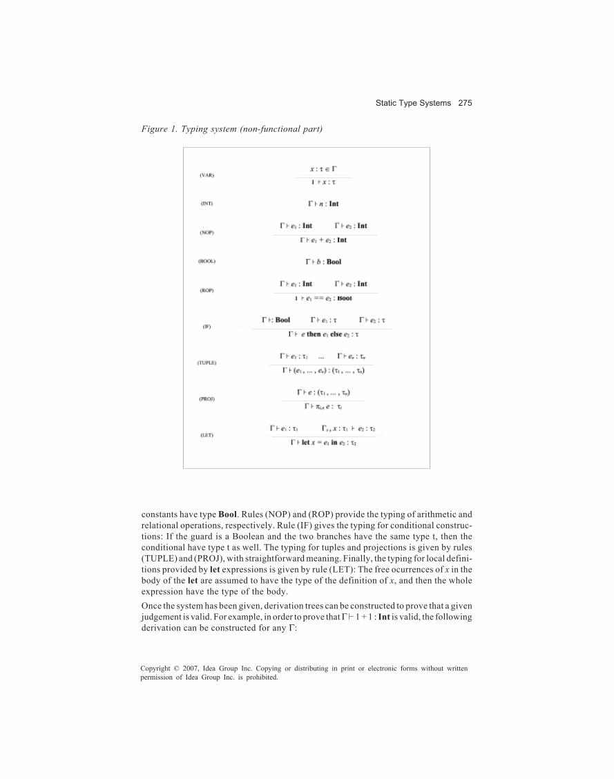
Static Type Systems 275
Copyright © 2007, Idea Group Inc. Copying or distributing in print or electronic forms without writtenpermission of Idea Group Inc. is prohibited.
constants have type Bool. Rules (NOP) and (ROP) provide the typing of arithmetic andrelational operations, respectively. Rule (IF) gives the typing for conditional construc-tions: If the guard is a Boolean and the two branches have the same type t, then theconditional have type t as well. The typing for tuples and projections is given by rules(TUPLE) and (PROJ), with straightforward meaning. Finally, the typing for local defini-tions provided by let expressions is given by rule (LET): The free ocurrences of x in thebody of the let are assumed to have the type of the definition of x, and then the wholeexpression have the type of the body.Once the system has been given, derivation trees can be constructed to prove that a givenjudgement is valid. For example, in order to prove that Γ 1 + 1 : Int is valid, the followingderivation can be constructed for any Γ:
Figure 1. Typing system (non-functional part)
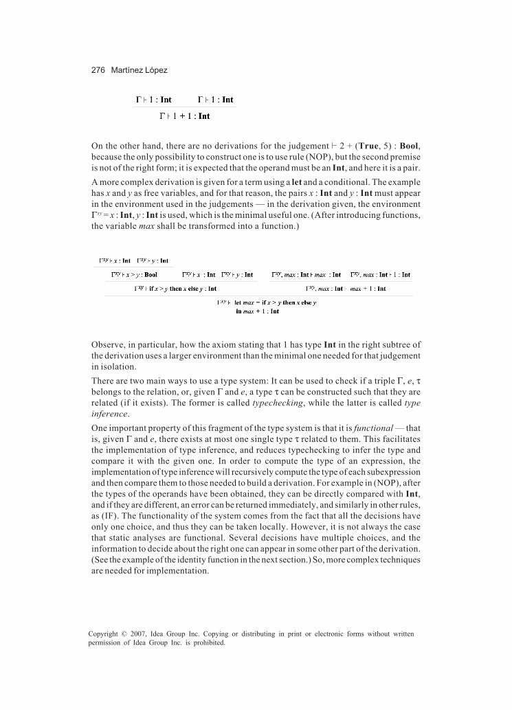
276 Martínez López
Copyright © 2007, Idea Group Inc. Copying or distributing in print or electronic forms without writtenpermission of Idea Group Inc. is prohibited.
On the other hand, there are no derivations for the judgement � 2 + (True, 5) : Bool,because the only possibility to construct one is to use rule (NOP), but the second premiseis not of the right form; it is expected that the operand must be an Int, and here it is a pair.A more complex derivation is given for a term using a let and a conditional. The examplehas x and y as free variables, and for that reason, the pairs x : Int and y : Int must appearin the environment used in the judgements — in the derivation given, the environmentΓxy = x : Int, y : Int is used, which is the minimal useful one. (After introducing functions,the variable max shall be transformed into a function.)
Observe, in particular, how the axiom stating that 1 has type Int in the right subtree ofthe derivation uses a larger environment than the minimal one needed for that judgementin isolation.There are two main ways to use a type system: It can be used to check if a triple Γ, e, τbelongs to the relation, or, given Γ and e, a type τ can be constructed such that they arerelated (if it exists). The former is called typechecking, while the latter is called typeinference.One important property of this fragment of the type system is that it is functional — thatis, given Γ and e, there exists at most one single type τ related to them. This facilitatesthe implementation of type inference, and reduces typechecking to infer the type andcompare it with the given one. In order to compute the type of an expression, theimplementation of type inference will recursively compute the type of each subexpressionand then compare them to those needed to build a derivation. For example in (NOP), afterthe types of the operands have been obtained, they can be directly compared with Int,and if they are different, an error can be returned immediately, and similarly in other rules,as (IF). The functionality of the system comes from the fact that all the decisions haveonly one choice, and thus they can be taken locally. However, it is not always the casethat static analyses are functional. Several decisions have multiple choices, and theinformation to decide about the right one can appear in some other part of the derivation.(See the example of the identity function in the next section.) So, more complex techniquesare needed for implementation.

Static Type Systems 277
Copyright © 2007, Idea Group Inc. Copying or distributing in print or electronic forms without writtenpermission of Idea Group Inc. is prohibited.
Typing Functions
The real expressive power of this language comes with the use of functions. Theexpression (λx.e) denotes an anonymous function: When this function is given anargument in place of x, the body e of the function is returned. Thus, the type of thisexpression is a function space: If under the assumption that x has type τ2, e has typeτ1, then the function has type (τ2 → τ1). Corresponding with this notion, the application(f e) is the operation that provides the argument e to a function f: if f is the function (λx.e’),the meaning of (f e) is the value of the body e’, where x is substituted by e. For example,when f is (λx.x+x), the meaning of (f 2) is 2 + 2, that is, 4.A common notational convention is that function types associate to the right, inaccordance with the convention that function application associates to the left; thus,when considering the function plus, defined as (λx.λy.x + y), the application is written(plus 2 3) — for ((plus 2) 3) — while its type is written (Int → Int → Int) — for (Int → (Int→ Int)); the meaning is that plus is a function taking an integer x and returning a functionof y into the result. By means of this convention it is simpler to understand plus as afunction “with two arguments,” even when formally it has only one. This is calledcurrification; see later.The typing rules for the functional fragment of the language, originally due to Hindley(1969), are given in Figure 2. Rule (LAM) establishes the typing of functions as explainedabove. Rule (APP) establishes the typing of applications: When e1 is a function and e2has the type of its argument, then the application (e1 e2) has the type of the result. Finally,rule (FIX) establishes the typing for recursive expressions: As (fix e) is a fixpoint of e,its type is that of the arguments, or identically, the results, of the function.
Figure 2. Typing system (functional part)
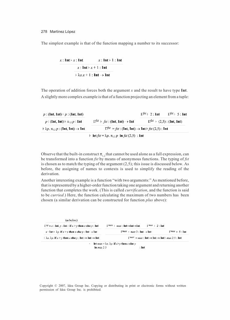
278 Martínez López
Copyright © 2007, Idea Group Inc. Copying or distributing in print or electronic forms without writtenpermission of Idea Group Inc. is prohibited.
The simplest example is that of the function mapping a number to its successor:
The operation of addition forces both the argument x and the result to have type Int.A slightly more complex example is that of a function projecting an element from a tuple:
Observe that the built-in construct π1,2 that cannot be used alone as a full expression, canbe transformed into a function fst by means of anonymous functions. The typing of fstis chosen as to match the typing of the argument (2,5); this issue is discussed below. Asbefore, the assigning of names to contexts is used to simplify the reading of thederivation.Another interesting example is a function “with two arguments:” As mentioned before,that is represented by a higher-order function taking one argument and returning anotherfunction that completes the work. (This is called currification, and the function is saidto be curried.) Here, the function calculating the maximum of two numbers has beenchosen (a similar derivation can be constructed for function plus above):
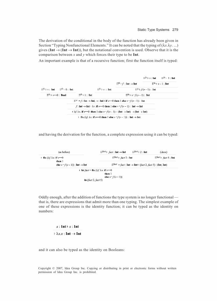
Static Type Systems 279
Copyright © 2007, Idea Group Inc. Copying or distributing in print or electronic forms without writtenpermission of Idea Group Inc. is prohibited.
The derivation of the conditional in the body of the function has already been given inSection “Typing Nonfunctional Elements.” It can be noted that the typing of (λx.λy. ...)gives (Int → (Int → Int)), but the notational convention is used. Observe that it is thecomparison between x and y which forces their type to be Int.An important example is that of a recursive function; first the function itself is typed:
and having the derivation for the function, a complete expression using it can be typed:
Oddly enough, after the addition of functions the type system is no longer functional —that is, there are expressions that admit more than one typing. The simplest example ofone of these expressions is the identity function; it can be typed as the identity onnumbers:
and it can also be typed as the identity on Booleans:
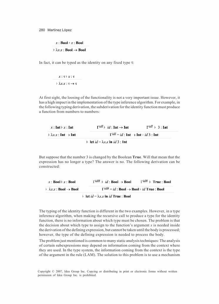
280 Martínez López
Copyright © 2007, Idea Group Inc. Copying or distributing in print or electronic forms without writtenpermission of Idea Group Inc. is prohibited.
In fact, it can be typed as the identity on any fixed type τ:
At first sight, the loosing of the functionality is not a very important issue. However, ithas a high impact in the implementation of the type inference algorithm. For example, inthe following typing derivation, the subderivation for the identity function must producea function from numbers to numbers:
But suppose that the number 3 is changed by the Boolean True. Will that mean that theexpression has no longer a type? The answer is no. The following derivation can beconstructed:
The typing of the identity function is different in the two examples. However, in a typeinference algorithm, when making the recursive call to produce a type for the identityfunction, there is no information about which type must be chosen. The problem is thatthe decision about which type to assign to the function’s argument x is needed insidethe derivation of the defining expression, but cannot be taken until the body is processed;however, the type of the defining expression is needed to process the body.The problem just mentioned is common to many static analysis techniques: The analysisof certain subexpressions may depend on information coming from the context wherethey are used. In the type system, the information coming from the context is the typeof the argument in the rule (LAM). The solution to this problem is to use a mechanism

Static Type Systems 281
Copyright © 2007, Idea Group Inc. Copying or distributing in print or electronic forms without writtenpermission of Idea Group Inc. is prohibited.
to defer decisions and another one to take those deferred decisions and communicatethem to the rest of the algorithm. Such a solution is presented in the next section.
The Implementation of Type Inference
In the previous section, the specification of a type system has been studied, and theproblem regarding the implementation of type inference was stated. In this section, analgorithm is completely designed and implemented. The correctness and completenessof the given algorithm is stated, and although the proof is not given, similar proofs canbe found in the literature — for example, Jones (1994a).This section is divided into two parts. Firstly, the design of the algorithm is presentedin the style of proof systems; however, the rules presented here are completelyfunctional, and so they can be read directly as the design of a program. This design,originally introduced by Rèmy (1989), uses two formal mechanisms: variables andsubstitutions. Additionally, the correctness and completeness of the algorithm arestated as two theorems. Second, an almost direct coding in the language Java ispresented, discussing its relation with the given design. More efficient ways to code thealgorithm can be given, but the one presented here illustrates better the importantfeatures to be taken into account, without the clutter of subtle implementation tricks.
Designing an Algorithm for Type Inference
For the design of the algorithm for type inference, two mechanisms are needed. The firstone is the addition of type variables in order to be able to express decisions that aredeferred: When a decision has to be made but there is not enough information available,a new type variable is introduced; later, when the information becomes available, thevariable can be replaced by the correct information. These new type variables are not partof the language presented to the programmer, but only a tool used inside the implemen-tation (this will change when adding polymorphism). So, for the algorithm, the actual typelanguage used is the following one:
τ ::= t | Int | Bool | (τ, ... , τ) | τ→τ
The new syntactic category t stands for a countably infinite set of type variables (disjointfrom the set of term variables). Observe that type variables can appear in any place wherea type is needed; however, only ground types (i.e., with no variables) are accepted asresult of the algorithm.The second mechanism needed to design the type inference algorithm is one allowingthe recording of decisions taken, in order to propagate them to the rest of the derivationtree. Substitutions are perfect for this task.

282 Martínez López
Copyright © 2007, Idea Group Inc. Copying or distributing in print or electronic forms without writtenpermission of Idea Group Inc. is prohibited.
• Definition 3.1: A substitution, denoted by S, is a function from type variables totypes (formally, S : t → τ), where only a finite number of variables are mapped tosomething other than themselves.
The denotation for the application of a substitution S to a variable t is written (S t). Thesubstitution mapping every variable to itself — the identity substitution — is denotedId. The substitution mapping variable t to type τ, and all the rest to themselves is denoted[t: = τ], so [t: = τ] t = τ, and [t: = τ] t’ = t’ for t’ ≠ t. Similarly, a substitution mapping ti totype τi for i = 1..n is denoted [t1: = τ1, ... , tn: = τn].Substitutions are extended to operate on types in a homomorphic way—that is, everyvariable t appearing in the type being substituted is replaced by (S t). Formally this isdenoted as S*, and defined as:
1 1
1 1
**Int Int*Bool Bool*( ,..., ) ( * ,..., * )*( ) ( * ) ( * )
n n
n n
S t StSSS S SS S S
τ τ τ ττ τ τ τ
= = = =
→ = →
By abuse of notation, the form (S τ) is also used for types.
The composition of substitutions is defined using the extension to types; thecomposition of substitution S with substitution T is denoted (S T), and defined as(S T) t = S* (T t). However, by using the abuse of notation, this definition can also bewritten as (S T) t = S (T t), thus resembling the standard notion of function composition.
The final notion regarding substitutions is its extension to operate on typing environ-ments. The idea is that applying a substitution to an environment amounts to applyingthe substitution to every type appearing in the environment. Thus, if Γ = x1 : τ1, ..., xn :τn, then S* Γ = x1 : S* τ1, ..., xn : S* τn. Once again, the notation can be abused, thus definingS Γ = x1 : S τ1, ..., xn : S τn instead.
Variables are used to defer decisions, and substitutions are used to record a decision thathas been taken. But, where are decisions actually taken? In order to formalize that idea,the notion of unifier has to be introduced. A unifier for types τ and τ’ is a substitutionS such that S τ = S τ’. If given two types, there exists a unifier for them, the types are saidto be unifiable.
Unifiers are not unique, but they can be ordered by a more general order: A unifier S forτ and τ’ is more general than a unifier T for the same types, denoted S > T, if there exista substitution R such that T = R S. The composition of substitutions is used in thedefinition. The idea is that a unifier is more general than another one if it takes lessdecisions to unify the two types; the substitution R is encoding the remaining decisionstaken by T. Given two unifiable types, there always exists a most general unifier, that is,

Static Type Systems 283
Copyright © 2007, Idea Group Inc. Copying or distributing in print or electronic forms without writtenpermission of Idea Group Inc. is prohibited.
a unifier that is more general than any other for those types; most general unifiers are notunique, however they differ only in the name of variables. This can be observed in theabove-mentioned substitution R: It only maps variables to variables (and it is called arenaming for that reason).
For example, taking τ = Int → t1 → t2 and t’ = τ3 → Bool → t4, two possible unifiers for τand τ’ are S1 = [t1:=Bool, t2:=t4, t3:=Int] and S2 = [t1:=Bool, t2:= t5 → t5, t3:=Int, t4:=t5 → t5];in this case, S1 > S2, being R = [t4:=t5 → t5]; it is the case also that S1 is a most general unifier.Another most general unifier for the two types is S3 = [t1:=Bool, t2:=t6 , t3:=Int, t4:=t6];observe that S1 > S3, by virtue of R1 = [t4:=t6] and also that S3 > S1, by virtue of R2 = [t6:=t4]— observe that both R1 and R2 are renamings.It may be the case that given two types, there exist no unifier for them. There are twosources for this situation in the language presented here. The first one is common to anylanguage with constants and type constructors: Two expressions constructed withdifferent constructors cannot be unified. For example, there is no unifier for types Int andBool, or for types Bool and Int → Int, and so on. The second one is subtler: It is relatedwith the unification of a variable t with a type containing an occurrence of such a variable.For example, there are no unifiers for t1 and (t1 → Int), because the only choice is tosubstitute t1 for an infinite type ((…→Int) → Int) → Int); however this language containsno infinite types. There are languages of types where there is a solution for the unificationof these two types. (See the extension of the typing system with recursive types inSection Recursive Types.)The first part of the implementation is to design an algorithm calculating the mostgeneral unifier of two given types. This algorithm, called unification, is written usingjudgements of the form τ ~S τ’, meaning that S is a most general unifier for τ and τ’. Therules defining the unification system are given in Figure 3.
Figure 3. Unification algorithm
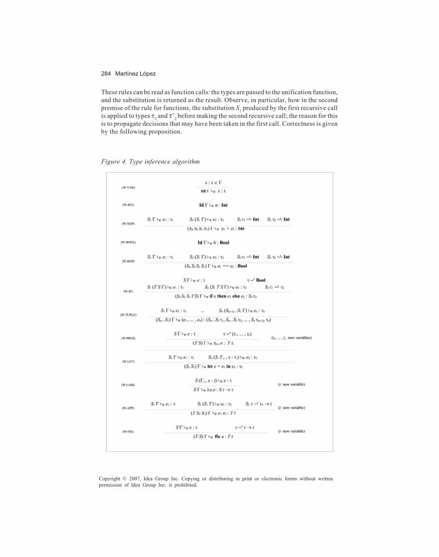
284 Martínez López
Copyright © 2007, Idea Group Inc. Copying or distributing in print or electronic forms without writtenpermission of Idea Group Inc. is prohibited.
These rules can be read as function calls: the types are passed to the unification function,and the substitution is returned as the result. Observe, in particular, how in the secondpremise of the rule for functions, the substitution S1 produced by the first recursive callis applied to types τ2 and τ’2 before making the second recursive call; the reason for thisis to propagate decisions that may have been taken in the first call. Correctness is givenby the following proposition.
Figure 4. Type inference algorithm

Static Type Systems 285
Copyright © 2007, Idea Group Inc. Copying or distributing in print or electronic forms without writtenpermission of Idea Group Inc. is prohibited.
• Proposition 3.2: Types τ and τ’ are unifiable iff τ ~S τ’ for some substitution Ssatisfying that S τ = S τ’ and for all T such that T τ = T τ’, S > T. That is, the typesτ and τ’ are unifiable iff the unification algorithm returns a substitution S thatis a most general unifier for τ and τ’.
A coding of the unification algorithm must take into account the possibility of failure,encoding it in an appropriate form — for example, by returning a boolean establishingthe success of the operation, and the substitution in case that the boolean is True.The algorithm for type inference is also specified by using a formal system whose rulesthat can be understood as function calls. The judgments used for this system have theform S Γ �W e : τ, where the environment Γ and the expression e are inputs, and thesubstitution S and the type τ are outputs (the W in the judgement is there for historicalpurposes. Such was the name used by Milner for his inference algorithm). The rules forthis system are given in Figure 4.The rules look much more complicated than they really are, because of the need topropagate substitutions obtained in each recursive call to subsequent calls. In particular,the notation S2 (S1 Γ) is used to indicate that the environment (S1 Γ) is used as input, andsubstitution S2 is obtained as output. In contrast with (S2 S1) Γ, used to indicate that Γis the input and the composition (S2 S1), the output (see rules (W-NOP), (W-ROP), (W-IF), (W-TUPLE), (W-LET), and (W-APP)). Another important thing to observe is that noassumption is made about the type returned by a recursive call. Instead, unification isused to make decisions forcing it to have the desired form afterwards (see rules (W-NOP),(W-ROP), (W-IF), (W-PROJ), (W-APP), and (W-FIX)). A final observation is concernedwith the side conditions of the form (t new variable). The idea is that t is a variable notused in any other part of the derivation tree. This is a global condition, and anyimplementation has to take care of it.As an example, the use of the algorithm to type the identity function is presented:
Observe how a type containing variables is returned (together with the identity substi-tution).Considering again the two uses of the identity function on numbers and booleans, butusing the algorithm to obtain the derivations, it can be seen that the recursive call fortyping the identity is always the same, and that it is the unification in rule (W-APP) whichgives the variable its right value.
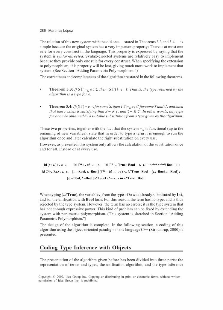
286 Martínez López
Copyright © 2007, Idea Group Inc. Copying or distributing in print or electronic forms without writtenpermission of Idea Group Inc. is prohibited.
The relation of this new system with the old one — stated in Theorems 3.3 and 3.4 — issimple because the original system has a very important property: There is at most onerule for every construct in the language. This property is expressed by saying that thesystem is syntax-directed. Syntax-directed systems are relatively easy to implementbecause they provide only one rule for every construct. When specifying the extensionto polymorphism, this property will be lost, giving much more work to implement thatsystem. (See Section “Adding Parametric Polymorphism.”)The correctness and completeness of the algorithm are stated in the following theorems.
• Theorem 3.3: If S Γ �W e : τ, then (S Γ) � e : τ. That is, the type returned by thealgorithm is a type for e.
• Theorem 3.4: If (S Γ) � e : τ for some S, then T Γ �W e : τ’ for some T and τ’, and suchthat there exists R satisfying that S = R T, and τ = R τ’. In other words, any typefor e can be obtained by a suitable substitution from a type given by the algorithm.
These two properties, together with the fact that the system �W is functional (up to therenaming of new variables), state that in order to type a term it is enough to run thealgorithm once and later calculate the right substitution on every use.However, as presented, this system only allows the calculation of the substitution onceand for all, instead of at every use.
When typing (id True), the variable tx from the type of id was already substituted by Int,and so, the unification with Bool fails. For this reason, the term has no type, and is thusrejected by the type system. However, the term has no errors; it is the type system thathas not enough expressive power. This kind of problem can be fixed by extending thesystem with parametric polymorphism. (This system is sketched in Section “AddingParametric Polymorphism.”)The design of the algorithm is complete. In the following section, a coding of thisalgorithm using the object-oriented paradigm in the language C++ (Stroustrup, 2000) ispresented.
Coding Type Inference with Objects
The presentation of the algorithm given before has been divided into three parts: therepresentation of terms and types, the unification algorithm, and the type inference
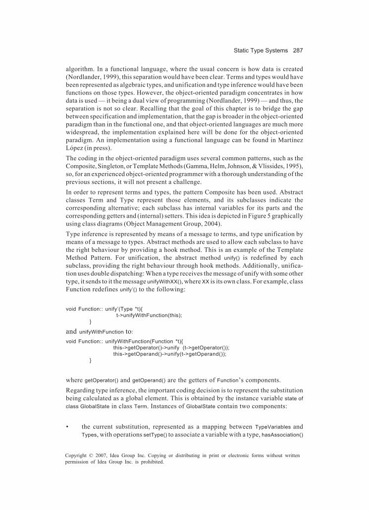
Static Type Systems 287
Copyright © 2007, Idea Group Inc. Copying or distributing in print or electronic forms without writtenpermission of Idea Group Inc. is prohibited.
algorithm. In a functional language, where the usual concern is how data is created(Nordlander, 1999), this separation would have been clear. Terms and types would havebeen represented as algebraic types, and unification and type inference would have beenfunctions on those types. However, the object-oriented paradigm concentrates in howdata is used — it being a dual view of programming (Nordlander, 1999) — and thus, theseparation is not so clear. Recalling that the goal of this chapter is to bridge the gapbetween specification and implementation, that the gap is broader in the object-orientedparadigm than in the functional one, and that object-oriented languages are much morewidespread, the implementation explained here will be done for the object-orientedparadigm. An implementation using a functional language can be found in MartínezLópez (in press).The coding in the object-oriented paradigm uses several common patterns, such as theComposite, Singleton, or Template Methods (Gamma, Helm, Johnson, & Vlissides, 1995),so, for an experienced object-oriented programmer with a thorough understanding of theprevious sections, it will not present a challenge.In order to represent terms and types, the pattern Composite has been used. Abstractclasses Term and Type represent those elements, and its subclasses indicate thecorresponding alternative; each subclass has internal variables for its parts and thecorresponding getters and (internal) setters. This idea is depicted in Figure 5 graphicallyusing class diagrams (Object Management Group, 2004).Type inference is represented by means of a message to terms, and type unification bymeans of a message to types. Abstract methods are used to allow each subclass to havethe right behaviour by providing a hook method. This is an example of the TemplateMethod Pattern. For unification, the abstract method unify() is redefined by eachsubclass, providing the right behaviour through hook methods. Additionally, unifica-tion uses double dispatching: When a type receives the message of unify with some othertype, it sends to it the message unifyWithXX(), where XX is its own class. For example, classFunction redefines unify’() to the following:
void Function:: unify’(Type *t){ t->unifyWithFunction(this);
}
and unifyWithFunction to:
void Function:: unifyWithFunction(Function *t){this->getOperator()->unify (t->getOperator());this->getOperand()->unify(t->getOperand());
}
where getOperator() and getOperand() are the getters of Function’s components.Regarding type inference, the important coding decision is to represent the substitutionbeing calculated as a global element. This is obtained by the instance variable state ofclass GlobalState in class Term. Instances of GlobalState contain two components:
• the current substitution, represented as a mapping between TypeVariables andTypes, with operations setType() to associate a variable with a type, hasAssociation()

288 Martínez López
Copyright © 2007, Idea Group Inc. Copying or distributing in print or electronic forms without writtenpermission of Idea Group Inc. is prohibited.
informing if a given variable has an association, and getType() returning the typeassociated to a variable if it exists, and
• a seed, with an operation freshType() used to calculate a new type variable (onenever used before in the derivation; thus its global nature) in those rules thatrequire it.
Instead of performing the application of the substitution to every element immediately,the substitution is recorded in the state, and applied only when the type has to beaccessed. The coding of this behaviour is given by the methods apply() and unfold() ofclass Type: apply() represents the application of a substitution to a type variable (i.e., itstops the application of the substitution as soon as something different from a variableis found), while unfold() represents the application of a substitution to a type (i.e., itapplies the substitution to all the parts of the type, recursively). The difference betweenapply() and unfold() is due to the behaviour of unification. When unification is performed,new associations between type variables and types (corresponding to the decisionstaken by the algorithm) are made on every subterm, and those new associations wouldhave not been taken into account by unfold(); instead, apply() is used at every subterm,performing an incremental unfolding that has taken into account the last associationscalculated. The code of apply() and unfold() is identical at class TypeVariable, but differsin Function.
Figure 5. Class diagram for type inference in the object-oriented paradigm

Static Type Systems 289
Copyright © 2007, Idea Group Inc. Copying or distributing in print or electronic forms without writtenpermission of Idea Group Inc. is prohibited.
type* Type:: unfold(State s){return this;
}Type* TypeVariable:: unfold(State s){
if (!s->hasAssociation(this->getName)) return this;else return (s->getType(this->getName())->unfold(s));
}Type* Function:: unfold(State s){
this->setOperand(this->getOperand()->unfold(s));this->setOperator(this->getOperator()->unfold(s));return this;
}Type* Type:: apply(State s){
return this;}Type* TypeVariable:: apply(State s){
if (!s->hasAssociation(this->getName)) return this;else return (s->getType(this->getName())->apply(s));
}
The coding of method inferType in class Term just resets the global state with a new state(with the identity substitution and a base seed), and then it calls the abstract methodinfer, letting the subclasses provide the actual behaviour through hook methods.Environments used in the internal method infer are represented as mappings fromTermVariables to Types.
Type* Term:: inferType(){State* state = new State;state->initialState();Environment* g = new Environment;Type* t = this->infer(g,state)->unfold(state);delete g;return t;
}
Adding Parametric Polymorphism
In the last example of the section “Designing an Algorithm for Type Inference” a termhaving no type, but without errors, has been given. That example shows the limitationsof the simple type system presented. In this section, the basic type system is extendedwith parametric polymorphism, making it more powerful, and so, capable of typing termslike the one presented in the example.Recall that the problem was that the simple type system only allows the calculation ofthe substitution once and for all, instead of at every use. In order to solve the problem,some mechanism allowing multiple different instances for a given variable is needed. Thesolution is to quantify universally a type with variables, thus indicating that the

290 Martínez López
Copyright © 2007, Idea Group Inc. Copying or distributing in print or electronic forms without writtenpermission of Idea Group Inc. is prohibited.
quantified variables can take many different values. However, this has to be done withcare. If universal quantification is added in the same syntactic level as the rest of thetyping constructs, the system obtained becomes undecidable (Wells, 1994, 1998). Inorder to have polymorphism keeping decidability, Damas and Milner separate thequantification in a different level (Damas & Milner, 1982), thus having (monomorphic)types in one level, and type schemes (polymorphic types) in another one. The typesystem is designed in such a way that only declarations made in a let construct areallowed to be polymorphic. For that reason, it is sometimes called let-bounded polymor-phism. Another solution is to add type annotations into terms (Reynolds, 1998), resultingin the language called second order lambda calculus, but that alternative is not describedhere. The term language is the same, but the type language is changed.
• Definition 4.1: Types for a let-bounded polymorphic language are given by twosyntactic categories: monomorphic types, called also monotypes, denoted by τ,and polymorphic types, called type schemes, denoted by σ. The grammarsdefining these categories are the following:
τ ::= t | Int | Bool | (τ, ... , τ) | τ → τσ ::= τ | t.σ
Observe how monotypes can be seen as type schemes, but not the other way round. Oncea quantification has been introduced, no other type constructions can be used. Thisforces the elements of tuples and the arguments and results of functions to bemonomorphic (they can be made polymorphic in an outer level, but, for example, nopolymorphic function can be passed as argument. See the example at the end of thissection). The addition of quantification to types implies that the variables of a typeexpression are now divided into two groups: those that are quantified (bound variables)and those that are not (free variables). This notion is exactly the same as the one of freevariables in the term language, where is the binder and the s following it, its scope.The judgements to determine the typing of terms in the polymorphic system are verysimilar to those of the simply typed system. The only differences are that environmentsassociate variables with type schemes (instead of monotypes as before), and that theresulting type can be a type scheme. That is, the form of judgements is Γ � e : σ, whereΓ contains pairs of the form x : σ. The rules specifying the polymorphic typing are givenin Figure 6 (rules (P-INT), (P-NOP), (P-BOOL), and (P-ROP) are omitted because, beingmonomorphic in nature, they are identical to their counterpart in the simply typedsystem).The formulation of this system deserves explanation, because at first glance, it may seemalmost identical to the one given in the previous sections. However, the changes makeit more powerful. On the one hand, there are two new rules ((P-GEN) and (P-INST)) to allowthe quantification of type variables and their removal (by using substitutions). On theother hand, some rules have been changed to incorporate the notion of type scheme ((P-VAR), (P-IF), and, most notably, (P-LET)), while others ((P-TUPLE), (P-PROJ), (P-LAM),(P-APP), and (P-FIX)) remained exactly as before. This fact is represented by the use of
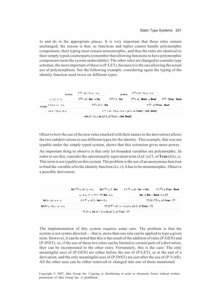
Static Type Systems 291
Copyright © 2007, Idea Group Inc. Copying or distributing in print or electronic forms without writtenpermission of Idea Group Inc. is prohibited.
τs and σs in the appropriate places. It is very important that these rules remainunchanged; the reason is that, as functions and tuples cannot handle polymorphiccomponents, their typing must remain monomorphic, and thus the rules are identical totheir simply typed counterparts (remember that allowing functions to have polymorphiccomponents turns the system undecidable). The other rules are changed to consider typeschemes; the most important of these is (P-LET), because it is the one allowing the actualuse of polymorphism. See the following example, considering again the typing of theidentity function used twice on different types.
Observe how the use of the new rules (marked with their names in the derivation) allowsthe two subderivations to use different types for the identity. This example, that was nottypable under the simply typed system, shows that this extension gives more power.
An important thing to observe is that only let-bounded variables are polymorphic. Inorder to see this, consider the operationally equivalent term (λid. (id 3, id True))(λx.x).This term is not typable on this system. The problem is the use of an anonymous functionto bind the variable id to the identity function (λx.x); it has to be monomorphic. Observea possible derivation:
The implementation of this system requires some care. The problem is that thesystem is not syntax directed — that is, more than one rule can be applied to type a giventerm. However, it can be noted that this is the result of the addition of rules (P-GEN) and(P-INST), so, if the use of these two rules can be limited to certain parts of a derivation,they can be incorporated to the other rules. Fortunately, this is the case: The onlymeaningful uses of (P-GEN) are either before the use of (P-LET), or at the end of aderivation; and the only meaningful uses of (P-INST) are just after the use of (P-VAR).All the other uses can be either removed or changed into one of those mentioned.
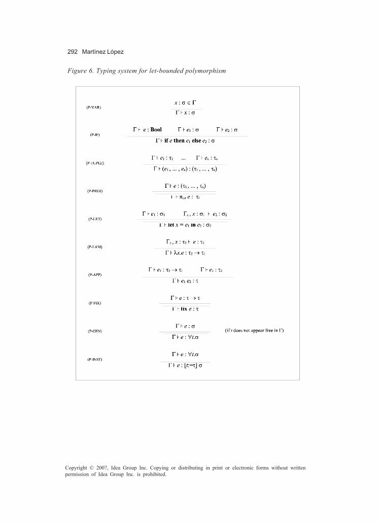
292 Martínez López
Copyright © 2007, Idea Group Inc. Copying or distributing in print or electronic forms without writtenpermission of Idea Group Inc. is prohibited.
Figure 6. Typing system for let-bounded polymorphism

Static Type Systems 293
Copyright © 2007, Idea Group Inc. Copying or distributing in print or electronic forms without writtenpermission of Idea Group Inc. is prohibited.
There are two mechanisms to incorporate the uses of these rules to a syntax-directedversion: one to capture (P-GEN), and the other for (P-INST). The first one is an operationto quantify exactly those variables that are important.
• Definition 4.2: Let A = { t1, ..., tn } be the set of free variables of type τ, from whichthe free variables appearing in Γ have been removed. Then GenΓ(τ) = ∀t1. ... ∀tn.τ.That is, the operation Gen quantifies all the free variables of a type except thosethat appear free in the environment.
The correspondence of this notion with the use of (P-GEN) is given in the followingproposition:
• Proposition 4.3: If Γ � e : τ, then Γ � e : GenΓ(τ), and both derivations differ onlyin the use of rule (P-GEN).
The second mechanism is a relationship between type schemes, according to how generalthey are. In order to define it, the notion of generic instance of a type scheme has to bedefined first.
• Definition 4.4: A type τ' is a generic instance of a type scheme σ = ∀t1. ... ∀tn.τ ifthere are types τ1, ..., τn such that [t1:=τ1 , ..., tn :=τn] τ = τ'.
For example, Int → Int is a generic instance of ∀t.t → t, and (t, t') → Bool is a genericinstance of ∀t1.∀t2.t1 → t2 .
• Definition 4.5: A type scheme σ is said to be more general than a type scheme σ',written σ ≥ σ', if every generic instance of σ' is a generic instance of σ.
For example, ∀t1. t2.t1 → t2 is more general than ∀t.∀t'.∀t''.(t, t') → Bool. Observe thatthere can be any number of quantifiers on the less general type scheme, as long as thevariables do not clash with those in the more general one.This definition of “more general” does not provide an easy way to calculate when twotypes are related. The following proposition provides a characterization giving asyntactic way to do that:
• Proposition 4.6: Let σ = ∀t1. ... ∀tnτ, and σ' = ∀t'1. ... ∀t'mτ'. and suppose none ofthe t'i appears free in σ. Then σ ≥ σ' if, and only if, there are types τ1, ..., τn such that[t1:=τ1 , ..., tn :=τn] τ = τ'.
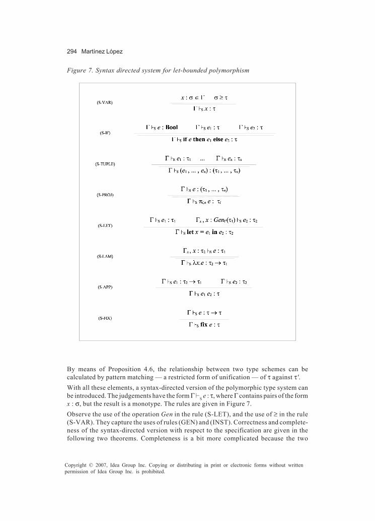
294 Martínez López
Copyright © 2007, Idea Group Inc. Copying or distributing in print or electronic forms without writtenpermission of Idea Group Inc. is prohibited.
By means of Proposition 4.6, the relationship between two type schemes can becalculated by pattern matching — a restricted form of unification — of τ against τ'.With all these elements, a syntax-directed version of the polymorphic type system canbe introduced. The judgements have the form Γ �S e : τ, where Γ contains pairs of the formx : σ, but the result is a monotype. The rules are given in Figure 7.Observe the use of the operation Gen in the rule (S-LET), and the use of ≥ in the rule(S-VAR). They capture the uses of rules (GEN) and (INST). Correctness and complete-ness of the syntax-directed version with respect to the specification are given in thefollowing two theorems. Completeness is a bit more complicated because the two
Figure 7. Syntax directed system for let-bounded polymorphism

Static Type Systems 295
Copyright © 2007, Idea Group Inc. Copying or distributing in print or electronic forms without writtenpermission of Idea Group Inc. is prohibited.
systems return elements of different syntactic categories; the specification returns a typescheme, and the syntax directed version, a monotype. However, they can be related byusing “more general.”
• Theorem 4.7: If Γ �S e : τ, then Γ � e : τ. That is, the type returned by the syntax-directed version is a type for e according to the specification.
• Theorem 4.8: If Γ � : σ, then Γ �S e : τ for some τ, and GenΓ(τ) ≥ σ. In other words,any type scheme for e can be obtained by instantiation of the generalization ofa type given by the syntax-directed system.
Consider a derivation of a type of the identity function using the syntax directed system:
Its generalization is ∀tx.tx → tx, and any other type scheme obtainable for the identityfunction (e.g., ∀t.(t, t) → (t, t), ∀t'.∀t''.(t' → t'') → (t' → t''), Int → Int, etc.) can be obtainedfrom the former by instantiation.The algorithm to calculate a type scheme for a given term in the polymorphic system isvery similar to the one given for the simply typed system. The most interesting rule isthat of variables, because it has to implement the instantiation prescribed by the “moregeneral” relation. This is obtained by substituting the quantified variables for new oneson every use of the rule, thus having the desired effect. All the remaining rules are easilydeducible.
The coding of this algorithm is an easy extension of the one presented in Section “CodingType Inference with Objects.” The only possible complication is the representation ofbound variables because free and bound variables can be mixed, and thus can causeconfusion. A good solution is to have two different representations for free and boundvariables and code the algorithms for generalization and instantiation accordingly.

296 Martínez López
Copyright © 2007, Idea Group Inc. Copying or distributing in print or electronic forms without writtenpermission of Idea Group Inc. is prohibited.
Other Extensionsto the Basic Type System
Type systems have been designed for almost all kinds of paradigms in programming, andfor almost all features — for example, records, arrays, variant types, not to mentionextensions to the language, overloading (Jones, 1994a, 1996; Odersky, Wadler, & Wehr,1995), recursive types, type systems for imperative features (Hoang, Mitchell, &Viswanathan, 1993; Wright, 1992, 1995), object oriented languages (Abadi & Cardelli,1996; Nordlander, 1999; Nordlander, 2000; von Oheimb & Nipkow, 1999; Syme, 1999;Wand, 1987), inheritance (Breazu-Tannen, Coquand, Gunter, & Scedrov, 1991; Wand,1991, 1994), persistency (Atkinson, Bailey, Chisholm, Cockshott, & Morrison, 1983;Atkinson & Morrison, 1988; Dearle, 1988; Morrison, Connor, Cutts, Kirby, & Stemple,1993), abstract datatypes (Mitchell & Plotkin, 1988), reactive systems (Hughes, Pareto,& Sabry, 1996; Nordlander, 1999), mobile systems (Freund & Mitchell, 1998; Igarashi &Kobayashi, 2001; Knabe, 1995), and others (Pottier, 2000; Shields & Meijer, 2001) in thefield of language features.There are also other ways to present type inference systems, the main alternative beingthe use of constraints (Aiken, 1999; Sulzmann, Odersky, & Wehr, 1997). In these systems,there are two phases for type inference: the first one, when the term is traversed andconstraints on type variables are collected, and a second phase of constraint solving,where a solution for all the constraints gathered is calculated. This form of presentationallows much more flexibility for the use of heuristics during constraint solving, and it ismore suitable when typing extensions to the basic system presented here. The theoryof qualified types for overloading and the framework of type specialization discussedbelow use this variation.In this section, some extensions will be presented. In the first part, basic extensions tothe language are considered. In the second part, extensions to the type system toconsider advanced features are covered. And in the last one, different type-basedanalyses are discussed.
Extending the Basic Language
Two important extensions a good language has to consider are the ability to managerecords and variant types (or sum types).
Records
Most languages provide records instead of tuples. Records are a variation of tuples withnamed components. Instead of referencing the elements by their position, there are labelsthat can be used to retrieve them. The projections πi,n e are then replaced by the accessingoperation e.li.
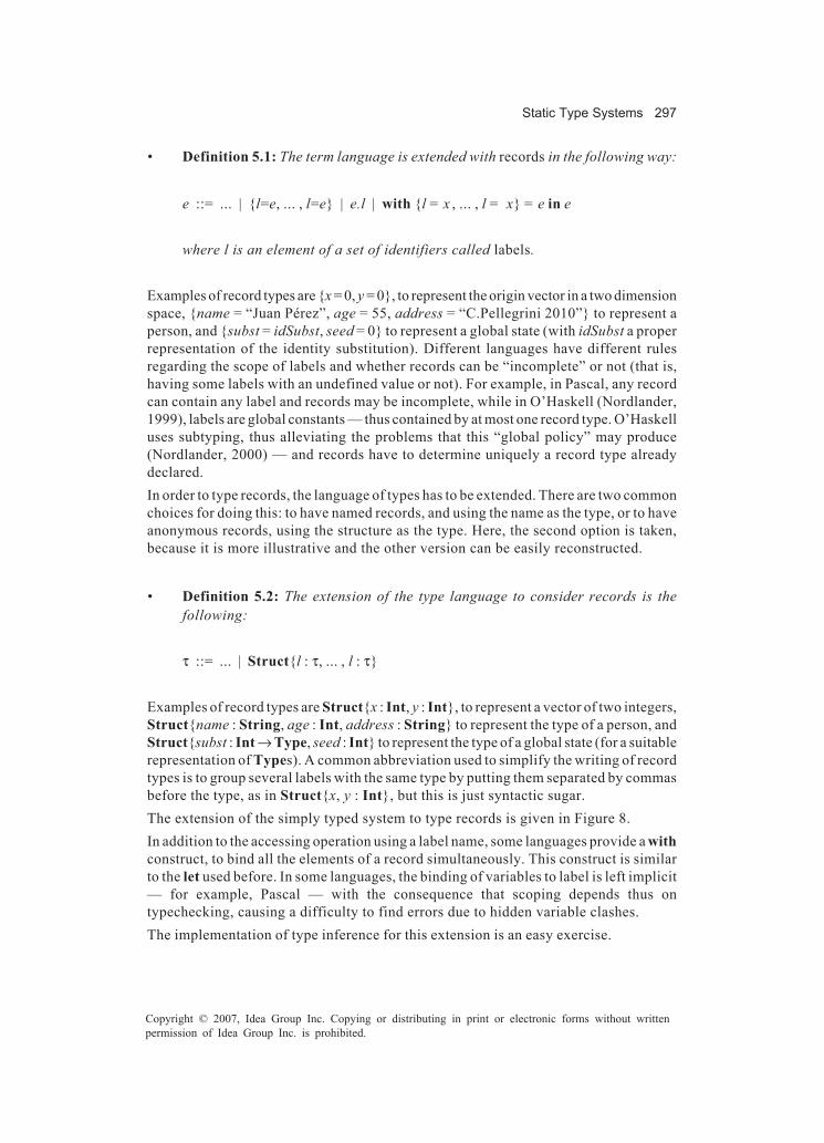
Static Type Systems 297
Copyright © 2007, Idea Group Inc. Copying or distributing in print or electronic forms without writtenpermission of Idea Group Inc. is prohibited.
• Definition 5.1: The term language is extended with records in the following way:
e ::= ... | {l=e, ... , l=e} | e.l | with {l = x , ... , l = x} = e in e
where l is an element of a set of identifiers called labels.
Examples of record types are {x = 0, y = 0}, to represent the origin vector in a two dimensionspace, {name = “Juan Pérez”, age = 55, address = “C.Pellegrini 2010”} to represent aperson, and {subst = idSubst, seed = 0} to represent a global state (with idSubst a properrepresentation of the identity substitution). Different languages have different rulesregarding the scope of labels and whether records can be “incomplete” or not (that is,having some labels with an undefined value or not). For example, in Pascal, any recordcan contain any label and records may be incomplete, while in O’Haskell (Nordlander,1999), labels are global constants — thus contained by at most one record type. O’Haskelluses subtyping, thus alleviating the problems that this “global policy” may produce(Nordlander, 2000) — and records have to determine uniquely a record type alreadydeclared.In order to type records, the language of types has to be extended. There are two commonchoices for doing this: to have named records, and using the name as the type, or to haveanonymous records, using the structure as the type. Here, the second option is taken,because it is more illustrative and the other version can be easily reconstructed.
• Definition 5.2: The extension of the type language to consider records is thefollowing:
τ ::= ... | Struct{l : τ, ... , l : τ}
Examples of record types are Struct{x : Int, y : Int}, to represent a vector of two integers,Struct{name : String, age : Int, address : String} to represent the type of a person, andStruct{subst : Int → Type, seed : Int} to represent the type of a global state (for a suitablerepresentation of Types). A common abbreviation used to simplify the writing of recordtypes is to group several labels with the same type by putting them separated by commasbefore the type, as in Struct{x, y : Int}, but this is just syntactic sugar.The extension of the simply typed system to type records is given in Figure 8.In addition to the accessing operation using a label name, some languages provide a withconstruct, to bind all the elements of a record simultaneously. This construct is similarto the let used before. In some languages, the binding of variables to label is left implicit— for example, Pascal — with the consequence that scoping depends thus ontypechecking, causing a difficulty to find errors due to hidden variable clashes.The implementation of type inference for this extension is an easy exercise.

298 Martínez López
Copyright © 2007, Idea Group Inc. Copying or distributing in print or electronic forms without writtenpermission of Idea Group Inc. is prohibited.
The combination of records and higher-order functions has been used to provide objectswithout classes in the language O’Haskell (Nordlander, 1999). This is an example of thepower that a good discipline of types providing neat combinations of different elementscan achieve.
Sum Types (Unions, Variants, or Tagged Types)
Sum types are important types for expressiveness, although they are less known thanthe rest of the type constructs. They consist of the union of several types, discriminatingfrom which addend a given value comes from; the usual way to discriminate is by meansof tags, and for that reason they also receive the name of tagged types. Another way inwhich they appear in programming languages is as variant records, although that is onlya weak implementation of the real notion of sums. The main purpose of variant recordsis to save memory and not to add expressiveness.There are several ways to present sum types. The most simple one consists of allowingseveral named tags — called constructors — with a single argument each; constructorswith more arguments can be expressed using tuples, and a special type called Unit or Voidneeded to have constant constructors. Other versions allow for constructors withmultiple arguments, to use unnamed tags (using indexes instead of constructors), to haveonly binary sums (multiple sums are obtained by combination), and so on.To start the presentation, the Unit type is given first. This type contains a single value,usually called unit, and it can be identified with a tuple with zero elements (so, followingthe notation used for tuples, both the type and its single element can be denoted by apair of parenthesis — ()). Another common notation for this type is to call it void, andits single element also void (for example, in C). The purpose of unit is to indicate that someuninteresting or unnecessary argument or result is being used.
Figure 8. Typing system (records)

Static Type Systems 299
Copyright © 2007, Idea Group Inc. Copying or distributing in print or electronic forms without writtenpermission of Idea Group Inc. is prohibited.
• Definition 5.3: The term language is extended with unit in the following way:e ::= ... | ()
• Definition 5.4: The extension of the type language to consider the Unit type is thefollowing:t ::= ... | ()
There is only one typing rule for unit, presented in Figure 9, with the rules for sum types.As a simple example of the use of unit, consider its use as filler:
let fst = λp. π1,2 p in (fst (2,()), fst (True,())
Here, the type of the first instance of fst used in the body of the local definition is (Int,()) → Int, and that of the second one is (Bool, ()) → Bool. More involved examples aregiven in conjunction with sums.Sum types are built with constructors — a special kind of function — and they areinspected with a construct called case; they can be thought of as a generalization of thenotion of booleans, with constructors in place of True and False, and case in place ofif-then-else. The syntax used here for sum types is given as follows:
• Definition 5.5: The term language is extended with sums in the following way:
e ::= ... | C e | case e of C x . e; ...; C x . ewhere C is an element of a set of identifiers called constructors.
The simplest example of sum types is an enumerative type. For example, to model colors,constructors with the names of the colors can be used — as in Red (), Blue (), and so on.Constructors need an argument, but as colors are supposed to be constants, they aregiven the meaningless unit value.Sum types used to type expressions using constructors respect the following syntax:
• Definition 5.6: The extension of the type language to consider sum types is thefollowing:
τ ::= ... | Variant{C : τ, ..., C : τ}

300 Martínez López
Copyright © 2007, Idea Group Inc. Copying or distributing in print or electronic forms without writtenpermission of Idea Group Inc. is prohibited.
This presentation provides anonymous sums, that is, they are represented by thepossible constructors used to build elements of the type. Different languages madedifferent decisions regarding this choice. The most used one is to assign a name to a sumtype, and then use the name when referring to it. The most important difference betweenthese alternatives is how the equivalence of two given types is calculated: They can beconsidered equal if they have the same set of constructors, regardless of their order —in one extreme — to being considered equal only if they have the same name — in theother one.In the case of the modelling of colors, their type can be, for example, Variant{Red:(),Yellow:(), Blue:()}, if only primary colors are modelled, or Variant{Red:(), Yellow:(),Blue:(), Orange:(), Green:(), Purple:()}, if both primary and secondary colors aremodelled.A slightly more complex example is that of basic geometric shapes. They can berepresented as the following type: Variant{Circle : Int, Rectangle : (Int,Int)}, and someof its elements can be given as Circle 10, Rectangle (3,5), and so on.The typing rules for expressions involving constructors are given in Figure 9. In the caseof rule (CONSTR), there is some freedom in the choice of the constructors not mentionedin the term; some variants regarding the possible accepted constructors there arepossible, and the choices are given by the restrictions in the equivalence of types, asdescribed. In the rule (CASE), this presentation forces the construct case to have onebranch for every constructor appearing in the type; however, other choices are alsopossible, allowing less constructors to be used. Again, this issue is related with typeequivalence between different sums.By using the case construct, functions over sums can be constructed. For example, thefollowing function calculates the area of a given shape (although in the given definitionof the language there are only integers, this example uses operations on floating pointnumbers, as the decimal number 3.14 as an approximation to number p, and the divisionby two):
Figure 9. Typing system (unit and sum types)

Static Type Systems 301
Copyright © 2007, Idea Group Inc. Copying or distributing in print or electronic forms without writtenpermission of Idea Group Inc. is prohibited.
let area = λs. case s of Circle x. 3.14*(x^2);Rectangle xy. (π1,2 xy * π2,2 xy)/2
in (area (Circle 5), area (Rectangle (2,4)))
The type of function area in this example is Variant{Circle : Int, Rectangle : (Int,Int)}→ Int.Sums can be combined with type variables, to obtain very flexible types. A classicexample is that of a variant type used to model the possibility of failure; several namesfor constructors can be used. Here, they are called Error and Ok. Thus, the type isVariant{ Error : String, Ok : τ }, for some τ. This type can be used to model the resultof a function calculating the minimum of a sequence of values, where Error “Emptysequence” can be used to model when there are no values, and Ok v to model that v isthe minimum.The real power of sums can be seen when combined with other types, as the caseof recursive types, presented in the following section.
Extending the Type System
Some important extensions are better considered extensions to the type system, ratherthan extensions to the language. Among those, recursive and qualified types areconsidered here.
Recursive Types
Recursive types are a powerful addition to a type system. Several different ways tointroduce recursion with types exist, being the most common one to use recursivedefinition of types (in combination with named types). However, the formal presentationof recursive types using names and equations is more complex than the anonymous one,thus, as the goal here is to keep simplicity, the latter have been chosen.The introduction of recursive types usually do not introduce new expressions on the termlanguage, although the presentation is more simple introducing two constructs asfollows:
• Definition 5.7: The term language is extended with two new constructs in thefollowing way:
e ::= ... | in e | out e

302 Martínez López
Copyright © 2007, Idea Group Inc. Copying or distributing in print or electronic forms without writtenpermission of Idea Group Inc. is prohibited.
These two constructs, in and out, are usually implicitly assumed in practical languages.Their purpose is to map a recursive type into its expansion, and back.The syntax of recursive types is obtained with an operator similar to fix: it maps a typefunction into its fixpoint. For historical purposes, this operator is denoted with the greekletter µ. The syntax of types is thus extended as follows:
• Definition 5.8: The extension of the type language to consider recursive types isthe following (in addition to type variables, as described in Section “Designingan Algorithm for Type Inference”):
τ ::= ... | µt.τ
The intended meaning of the type expression µt.τ is the solution of the equation t = τ,where variable t may occur in τ. A simple way to obtain that is to make µt.τ and [t:=µt.τ]τisomorphic (i.e., having the same structure); the result of this is that, assuming that µt.τrepresents the solution of the equation, replacing on every occurrence of t in τ must givethe same result. The term constructs in and out are functions from [t:=µt.τ]τ to µt.τ, andfrom µt.τ to [t:=µt.τ]τ, respectively. This is captured by the typing rules given in Figure10.Recursive types provide infinite expansion of type constructs. This feature allows, inparticular, extending the solutions to unification. When unifying a type variable t witha type containing it, say t → Int, the type µt. t → Int is a solution for it in this system;observe that the expansion of µt. t → Int is isomorphic to it, being that the conditionneeded.The real power of recursive types comes from the combination with other type constructs,as sums and tuples. A classic example is that of lists of a type tx; they can be representedas the type µtl.Variant{ Nil : (), Cons : (tx,tl) }. For example, the elements of this type whentx is Int are (in (Nil ())), (in (Cons (1, in (Nil ())))), (in (Cons (2, in (Cons (1, in (Nil ())))))),etc., as the following derivation shows:
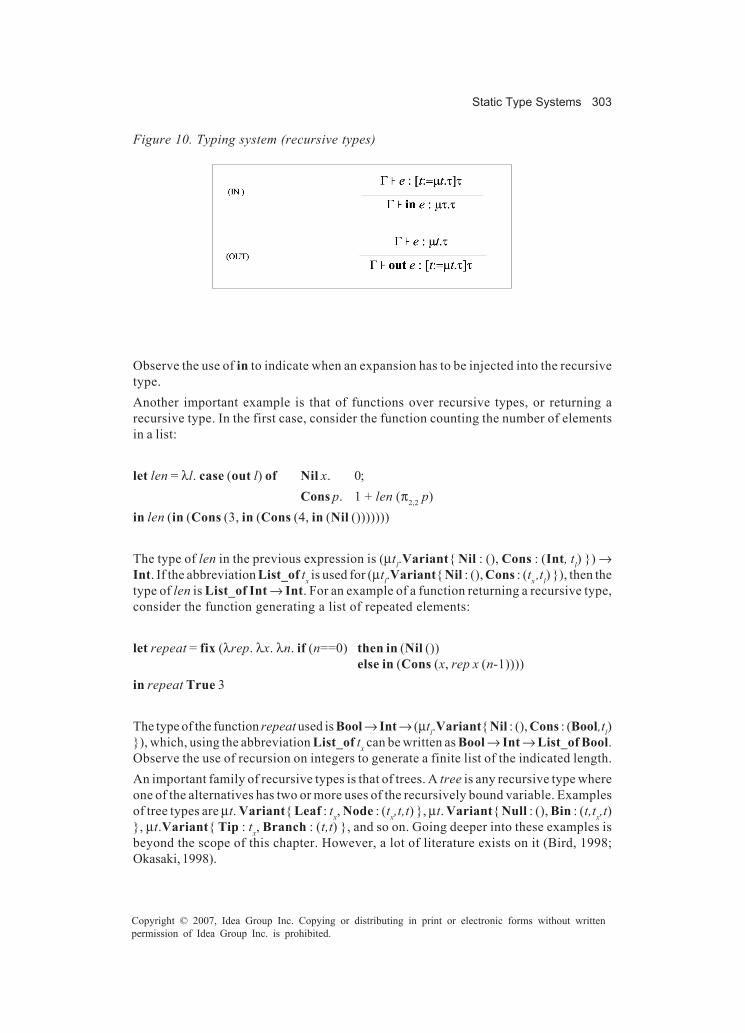
Static Type Systems 303
Copyright © 2007, Idea Group Inc. Copying or distributing in print or electronic forms without writtenpermission of Idea Group Inc. is prohibited.
Observe the use of in to indicate when an expansion has to be injected into the recursivetype.Another important example is that of functions over recursive types, or returning arecursive type. In the first case, consider the function counting the number of elementsin a list:
let len = λl. case (out l) of Nil x. 0;Cons p. 1 + len (π2,2 p)
in len (in (Cons (3, in (Cons (4, in (Nil ()))))))
The type of len in the previous expression is (µtl.Variant{ Nil : (), Cons : (Int, tl) }) →Int. If the abbreviation List_of tx is used for (µtl.Variant{ Nil : (), Cons : (tx ,tl) }), then thetype of len is List_of Int → Int. For an example of a function returning a recursive type,consider the function generating a list of repeated elements:
let repeat = fix (λrep. λx. λn. if (n==0) then in (Nil ())else in (Cons (x, rep x (n-1))))
in repeat True 3
The type of the function repeat used is Bool → Int → (µtl.Variant{ Nil : (), Cons : (Bool,tl)}), which, using the abbreviation List_of tx can be written as Bool → Int → List_of Bool.Observe the use of recursion on integers to generate a finite list of the indicated length.An important family of recursive types is that of trees. A tree is any recursive type whereone of the alternatives has two or more uses of the recursively bound variable. Examplesof tree types are µt. Variant{ Leaf : tx, Node : (tx,t,t) }, µt. Variant{ Null : (), Bin : (t,tx,t)}, µt.Variant{ Tip : tx, Branch : (t,t) }, and so on. Going deeper into these examples isbeyond the scope of this chapter. However, a lot of literature exists on it (Bird, 1998;Okasaki, 1998).
Figure 10. Typing system (recursive types)

304 Martínez López
Copyright © 2007, Idea Group Inc. Copying or distributing in print or electronic forms without writtenpermission of Idea Group Inc. is prohibited.
A final curiosity about the power of recursive types is that in a language with recursivetypes, the operator fix can be constructed. Thus, there is no need to provide it as aprimitive. A possible way to construct it is:
let prefix = λm. λf. f (out m m f) in prefix (in prefix)
The type of prefix is (µt. t → (tx → tx) → tx) → (tx → tx) → tx, and thus the type of (in prefix)is µt. t → (tx → tx) → tx obtaining the required type, (tx → tx) → tx, for fix. Verifying thatthis term has the desired behaviour is an easy exercise.
Qualified Types for Overloading
The theory of qualified types (Jones, 1994a) is a framework that allows the developmentof constrained type systems in an intermediate level between monomorphic and polymor-phic type disciplines. Qualified types can be seen in two ways: either as a restricted formof polymorphism, or as an extension of the use of monotypes (commonly described asoverloading, in which a function may have different interpretations according to thetypes of its arguments).Predicates are used to restrict the use of type variables, or, using the second point of view,to express several possible different instances with one single type (but without the fullgenerality of parametric polymorphism). The theory explains how to enrich types withpredicates, how to perform type inference using the enriched types, and which are theminimal properties predicates must satisfy in order for the resulting type system to havesimilar properties as in the Hindley-Milner one. In particular, it has been shown that anywell-typed program has a principal type that can be calculated by an extended versionof Milner’s algorithm.As we have seen, polymorphism is the ability to treat some terms as having many differenttypes, and a polymorphic type can be expressed by means of a type scheme, usinguniversal quantification to abstract those parts of a type that may vary. The idea ofqualified types is to consider a form of restricted quantification. If P(t) is a predicate ontypes and f(t) a type possibly containing variable t, the type scheme ∀ t.P(t)⇒f(t) canbe used to represent the set of types:
{ f(τ) s.t. τ is a type such that P(τ) holds. }
and accurately reflect the desired types for a given term.Thus, a key feature in the theory is the use of a language of predicates to describe setsof types (or, more generally, relations between types). The exact set of predicates mayvary from one instance of the framework to another, but the theory effectively capturesthe minimum required properties by using an entailment relation (�) between (finite) sets
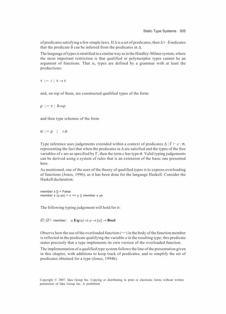
Static Type Systems 305
Copyright © 2007, Idea Group Inc. Copying or distributing in print or electronic forms without writtenpermission of Idea Group Inc. is prohibited.
of predicates satisfying a few simple laws. If ∆ is a set of predicates, then ∆ � δ indicatesthat the predicate δ can be inferred from the predicates in ∆.The language of types is stratified in a similar way as in the Hindley-Milner system, wherethe most important restriction is that qualified or polymorphic types cannot be anargument of functions. That is, types are defined by a grammar with at least theproductions:
τ ::= t | τ → τ
and, on top of them, are constructed qualified types of the form:
ρ ::= τ | δ⇒ρ
and then type schemes of the form
σ ::= ρ | t.σ
Type inference uses judgements extended within a context of predicates ∆ | Γ � e : σ,representing the fact that when the predicates in ∆ are satisfied and the types of the freevariables of e are as specified by Γ, then the term e has type σ. Valid typing judgementscan be derived using a system of rules that is an extension of the basic one presentedhere.As mentioned, one of the uses of the theory of qualified types is to express overloadingof functions (Jones, 1996), as it has been done for the language Haskell. Consider theHaskell declaration:
member x [] = Falsemember x (y:ys) = x == y || member x ys
The following typing judgement will hold for it:
∅ | ∅ � member : a.Eq(a) ⇒ a → [a] → Bool
Observe how the use of the overloaded function (==) in the body of the function memberis reflected in the predicate qualifying the variable a in the resulting type; this predicatestates precisely that a type implements its own version of the overloaded function.The implementation of a qualified type system follows the line of the presentation givenin this chapter, with additions to keep track of predicates, and to simplify the set ofpredicates obtained for a type (Jones, 1994b).

306 Martínez López
Copyright © 2007, Idea Group Inc. Copying or distributing in print or electronic forms without writtenpermission of Idea Group Inc. is prohibited.
Type-Based Analysis
The influence of the type discipline on program analysis, however, does not stop there.Typing techniques have been the inspiration for several developments in the fields ofprogram analysis and validation and verification techniques. Typing techniques havebeen modified to be applied to the calculation of different kinds of effects like type andeffects systems (Talpin & Jouvelot, 1992; Jouvelot & Gifford, 1991) — for example, typingreferences (Wright, 1992), register allocation (Agat, 1997), and so on—control flowanalysis (Mossin, 1996; Volpano, Smith, & Irvine, 1996), compilation (Wand, 1997),program transformation (Danvy, 1998; Hannan & Hicks, 1988; Hughes, 1996b; Romanenko,1990), code splicing (Thiemann, 1999), security (Volpano & Smith, 1997), and other formsof program analysis (O’Callahan, 1998).In the rest of this section, some of these developments are discussed.
Types and Effects
Types and effects are based on the idea of considering effects, which are an abstractionextending types to express the consequence of imperative operations on certain regions— the abstraction of possible aliased memory locations. A basic example of effects isthat of reading and writing a persistent memory — a possible syntax, where ε denoteseffects and ρ regions, is given by:
ε ::= ∅ | ς | init(ρ,τ) | read(ρ) | write(ρ) | ε∪ε
where ∅ denotes the absence of effects, ς denotes effect variables, the operators init,read, and write approximate effects on regions, and operator ∪ gathers different effectstogether. Types are extended to express effects by adding an effect expression to thefunction type: τ →ε τ, and a special type refρ(τ) to express a reference to an element oftype τ in region ρ. Typing judgements are also extended with effects, becoming Γ � e :τ,ε; the rules of the formal system are extended as well. Finally, basic operations onmemory locations are given types with effects. For example, the operator := for assign-ment receives the type ∀t.∀ρ.∀ς.∀ς'.refρ(t) →ς t →ς'∪write(ρ) (), expressing that theassignment takes a reference to a location and a value, and returns a command (of type()) whose effect is writing in the given region; other operations on locations are treatedsimilarly.
Types for Register Allocation
Register allocation is the process of deciding where, in which register or in the memory,to store each value computed by a program being compiled. In modern architectures, thedifference in access time between a register and a memory cell can be as much as 4 to 10

Static Type Systems 307
Copyright © 2007, Idea Group Inc. Copying or distributing in print or electronic forms without writtenpermission of Idea Group Inc. is prohibited.
times (or much more, if a cache miss occurs) (Henessy & Patterson, 1990). Moreover,typical RISC arithmetic can handle only register operands, and thus the difference in thenumber of required operations to add two numbers stored in registers against two storedin memory is of three instructions (two loads and a store of difference). For that reason,an optimal process of register allocation is crucial to obtain efficient programs.By its very nature, register allocation must be done late in the compilation process, whenthe order of evaluation of every subterm has been decided. Typical algorithms to performregister allocation operate on assembly-code level, when all structure and type informa-tion of the compiler’s intermediate language is lost. This means that calls to staticallyunknown functions must be made with some rigid calling convention, thus having therisk of requiring much more expensive operations due to misuse of registers. That is, ifthe register behaviour of the callee is known, the code produced to invoke the functioncan be optimized to use the best register allocation.Types and effects, as described in the previous section, can be used to provide a typesystem describing the behaviour of register usage of all objects in a program (Agat, 1997,1998). Types are enriched with register usage information, and the type system can beextended to perform optimal interprocedural register allocation, even when the functioninvoked is statically unknown. The main idea, then, is to move the register allocationphase from assembly-code to intermediate code, thus having all the power of types athand.Each type τ is annotated where the value of that type is, or is expected to be, stored, thusbecoming τr. Function types are modified to be of the form τr →
k;d τr , where k, called thekill-set, is a description of the registers that might be modified when the function isapplied, and d, called the displacement, describes which registers contain values thatmight then be referenced. Examples of such types are:
• IntR3 : Integer value stored in register 3.• IntS8 : Integer value stored in slot 8 of the current stack frame.
• (IntR2 →{R6,R4};{R3} IntR4)R5 : Function accepting an integer argument in register 2 and
returning an integer result in register 4. While computing the result, registers 6 and4 might be altered, and the value currently in register 3 might be needed in thecomputation. The pointer to the function closure is stored in register 5.
There are several benefits to using such a typed system expressing the registerassignments made by a register allocator. Since all values have a type, and types describeregister behaviour, specialized calling conventions can be used for all applications, eventhose whose functions are not known statically; it is the type of the argument functionthat tells how to call it. Additionally, a clean and simple setting for reasoning about thecorrectness of the register-allocation algorithm is gained. Finally, several optimizationscan be performed — for example, keeping values required by commonly used functionsin registers as much as possible.

308 Martínez López
Copyright © 2007, Idea Group Inc. Copying or distributing in print or electronic forms without writtenpermission of Idea Group Inc. is prohibited.
Sized Types
In the domain of safety-critical control systems (Levenson, 1986), a correct program isa program not causing any (unintentional) harm — like injury, damage, or death — to itsenvironment. Correctness properties like these require system-level reasoning. A par-ticular way in which one of these systems may cause harm is when some componentexceeds its memory limits, thus causing unintentional state changes, or even damage, tothe whole system. Errors of this kind are easy to introduce — a small change can do it,without notice — but are completely unacceptable. A formal technique allowing toreason about the memory limits of programs is thus a must.The theory of sized types (Pareto, 1998) is a framework composed by a language aimedat control systems programming, accompanied by tools asserting program correctnessfrom the memory consumption point of view. The main tool is a variation of a type systemaccepting only programs whose memory behaviour can be predicted. Some principles ofdesign underlying the theory of sized types guide the development of programs. Basicprinciples are that types may exclude bottom (a particular theoretical value that representnonterminating or erroneous computations) — that is, certain types can only be used fortype terminating programs — that types may distinguish finite, infinite, and partialvalues. For example, the availability of data from a given source can be assured by typingit with an infinite type with no partial values, and types may bound their values by sizeparameters in several dimensions. So, an upper bound in the number of elements of a list,or a lower bound on the number of elements produced by a data source can be determined(and those elements can also be bounded in size).The particular way to achieve the principles is by using data declarations with additionalinformation. For example, consider the following declarations:
data Bool = False | True
idata List ω a = Nil | Cons a (List ω a)
codata Stream ω a = Make a (Stream ω a)
data BS k = BS (Stream k Bool)
The first declaration establishes the type Bool as a sum type, but excludes explicitly thepossibility of undefined or nonterminating expressions of this type. Thus, if a programcan be typed with Bool, it can be asserted that it terminates and produces a value eitherFalse or True.The second declaration defines recursive sum types for lists, but adding an extraparameter ω. This new parameter is a bound on the size of the elements of the type, andthe keyword idata establishes that several new types are introduced, all finite: one forlists of size less than k for each possible natural number k, and the classical type for listsof any (finite) size.
Static Type Systems 309
Copyright © 2007, Idea Group Inc. Copying or distributing in print or electronic forms without writtenpermission of Idea Group Inc. is prohibited.
The third declaration uses the keyword codata to define that the elements of the declaredtype are infinite. It also has a bound parameter, but in this case it is used to determinea lower bound on the size of the streams. So, again, several new types are introduced:one for each natural number k of streams of size bigger than k, and one for streams thatwill always produce new data on demand.The last declaration has a parameter that fixes the size of the lower bound for the streamof Booleans declared.A carefully defined syntax for programs, and its corresponding semantics are needed toassure that all the desired principles are valid. A type system assigning sized types toprograms is defined, and also an algorithm calculating the assignment. In this way, thetype system can be used to assure the property of bounded size on typable programs(Hughes, Pareto, & Sabry, 1996).
Type Specialization
Program specialization is a form of a automatic program generation taking a given programas input to produce one or more particular versions of it as output, each specialized toparticular data. The program used as input is called the source program, and thoseproduced as output are called the residual programs.Type Specialization is an approach of program specialization introduced by JohnHughes in 1996 (Hughes, 1996a, 1996b, 1998) for typed languages. The main idea of typespecialization is to specialize both the source program and its type to a residual programand residual type. In order to do this, instead of a generalized form of evaluation — asthe one used in partial evaluation, the most common form of program specialization —type specialization uses a generalized form of type inference.The key question behind type specialization is:
How can the static information provided by the type of an expression be improved?
An obvious first step is to have a more powerful typesystem. But, it is also desirable toremove the static information expressed by this new type from the code in order to obtaina simpler and (hopefully) more efficient code. So, type specialization works with twotyped languages: the source language, in which the programs to be specialized are coded,and the residual language, in which the result of specialization is expressed. The sourcelanguage, whose elements are denoted by e, is a two-level language where everyconstruct is marked as either static or dynamic. Static information is supposed to bemoved to the type, while a dynamic one is supposed to be kept in the residual term; sourcetypes, denoted by τ, reflect the static or dynamic nature of expressions, and thus theyalso contain the marks. The residual language, whose terms and types are denoted bye’ and τ’ respectively, has constructs and types corresponding to all the dynamicconstructs and types in the source language, plus additional ones used to express theresult of specializing static constructs.

310 Martínez López
Copyright © 2007, Idea Group Inc. Copying or distributing in print or electronic forms without writtenpermission of Idea Group Inc. is prohibited.
In order to express the result of the specialization procedure, Hughes introduced a newkind of judgement and a formal system of rules to infer valid judgements. Thesejudgements, similar to typing judgements in the source language, make use of environ-ments to determine the specialization of free variables. The new judgements have the formΓ � e : τ e' : τ' which can be read as “if the free variables in e specialize to the expressionsindicated in Γ, then source expression e of source type τ specializes to residual expressione' and residual type τ' ”. The valid judgements are obtained by using a system of rulesspecifying how to specialize a given typed term; this system follows the same ideas oftyping systems.A very interesting example of type specialization is to specialize an interpreter for alanguage to a given term: given an interpreter int for a language and a program p writtenin it, the specialization of int to p is a program equivalent to p. This is called a Futamuraprojection (Futamura, 1971), and it compiles by specializing the interpreter. When thisway of compiling programs can be done optimally for all the programs in the language,then it can be assured that the specialization method can tackle all the constructs in it.Type specialization was the first approach obtaining optimality for compilation of typedlanguages by specialization.The implementation of a type specialization algorithm is rather tricky, and although JohnHughes has provided a prototype implementation (Hughes, 1997), it is difficult tounderstand, and properties about it are difficult to prove. However, Martínez López hasgiven a systematic way to implement type specialization following the lines presentedin this chapter (Martínez López & Hughes, 2002; Martínez López, 2005), together with aproof of a very important property of the system: the existence of a principal specializa-tion for every source term. Current research on type specialization involves the additionof sum types to the principal specialization system, and the addition of dynamicrecursion.
Conclusion
Type-based analyses are an important way to structure a system for verification orvalidation of programs. However, the design of a type-based analysis usually does notdirectly suggest a good way to implement it. This chapter has addressed the problem ofgoing from a specification of a type system to its implementation, showing several of thecommon subtleties that are a hindrance for designers and implementers. Additionally, thecorrectness and completeness of the implementation’s design were stated as theorems;their proofs are easy examples of induction on derivations, including several lemmas andadditional propositions. The case presented here is the most basic one, but it is usefulin order to cast light on the techniques needed.In addition, several extensions to the basic system were discussed, and several type-based analyses were mentioned and referenced. Some of the most important among themare register allocation, sized types, and type specialization; other approaches, such ascontrol-flow analysis and code splicing, that have not been considered are also impor-tant.

Static Type Systems 311
Copyright © 2007, Idea Group Inc. Copying or distributing in print or electronic forms without writtenpermission of Idea Group Inc. is prohibited.
Acknowledgments
I am very grateful to my colleague Eduardo Bonelli for his careful reading and his manysuggestions to improve the material presented here. I am also in debt to Jerónimo Irazábalbecause he agreed to translate my functional code to C++, even when the task was notas easy as it seemed at first. Two more people deserving my gratitude are Andrés Fortier,who has given his time to help me with the subtleties of the object oriented paradigm,and Alejandro Russo, who reviewed the early drafts. Finally, the anonymous referees,because they have given many suggestions on how to improve the chapter.
References
Abadi, M., & Cardelli, L. (1996). A theory of objects. Springer-Verlag.Aiken, A. (1999). Introduction to set constraint-based program analysis. Science of
Computer Programming, 35, 79-111.Agat, J. (1997). Types for register allocation. In IFL’97 (LNCS 1467).Agat, J. (1998). A typed functional language for expressing register usage. Licenciate
Dissertation. Chalmers University of Technology.Altenkirch, T., Gaspes, V., Nordström, B., & von Sydow, B. (1994). A user’s guide to ALF
(Technical report). Sweden: Chalmers University of Technology.Atkinson, M. P., Bailey, P. J., Chisholm, K. J., Cockshott, W. P., & Morrison, R. (1983).
An approach to persistent programming . Computer Journal, 26(4), 360-365.Atkinson, M. P., & Morrison, R. (1988). Types, bindings and parameters in a persistent
environment. In M.P. Atkinson, O. P. Buneman, & R. Morrison (Eds.), Data typesand persistence. Springer-Verlag.
Bertot, Y., & Castéran, P. (2004). Interactive theorem proving and program development.Coq’Art: The calculus of inductive constructions. In Texts in theoretical computerscience. An EATCS Series. Springer-Verlag.
Bird, R. (1998). An introduction to functional programming using Haskell. Prentice-Hall.
Breazu-Tannen, V., Coquand, T., Gunter, C. A., & Scedrov, A. (1991). Inheritance asimplicit coercion. Information and Computation, 93, 172-221.
Cardelli, L. (1997). Type systems. In CRC Handbook of computer science ad engineering(2nd ed.). CRC Press.
Cardelli, L., & Wegner, P. (1985). On understanding types, data abstraction, andpolymorphism. Computing Surveys, 17(4), 471-522.
Clément, D., Despeyroux, J., Despeyroux, T., & Kahn, G. (1986). A simple applicativelanguage: Mini-ML. In Proceedings of the 1986 ACM Conference on LISP andFunctional Programming (pp. 13-27). Cambridge, MA: ACM Press.
312 Martínez López
Copyright © 2007, Idea Group Inc. Copying or distributing in print or electronic forms without writtenpermission of Idea Group Inc. is prohibited.
The Coq proof assistant (2004). Retrieved from http://coq.inria.fr/ ECurry, H. B., & Feys,R. (1958). Combinatory logic. Amsterdam, The Netherlands: North Holland.
Coquand, T., & Huet, G. (1988). The calculus of constructions. Information andComputation, 76(2/3), 95-120.
Damas, L., & Milner, R. (1982). Principal type-schemes for functional languages. InProceedings of the Ninth Annual ACM Symposium on Principles of ProgrammingLanguages, Albuquerque, NM (pp. 207-212).
Danvy, O. (1998). Type-directed partial evaluation. In J. Hatcliff, T. E. Mogensen, & P.Thiemann (Eds.), Partial evaluation — Practice and theory (LNCS 1706, pp. 367-411). Copenhagen, Denmark: Springer-Verlag.
Dearle, A. (1988). On the construction of persistent programming environments. PhDthesis, University of St. Andrews.
Freund, S. N., & Mitchell, J. C. (1998). A type system for object initialization in the Javabytecode language. In Proceedings of the ACM Conference on Object-OrientedProgramming: Systems, Languages and Applications (OOPSLA’98) (pp. 310-328).
Futamra, Y. (1971). Partial evaluation and computation process — an approach to acompiler-compiler. Computer, Systems, Controls, 2(5), 45-50.
Gamma, R., Helm, R., Johnson, R., & Vlissides, J. (1995). Design patterns: Elements ofreusable object-oriented software. Addison Wesley.
Gaster, B. R., & Jones, M. P. (1996). A polymorphic type system for extensible recordsand variants (Tech. Rep. No. NOTTCS-TR-96-3). Department of Computer Science,University of Nottingham.
Girard, J. Y. (1989). Proofs and types. Cambridge University Press.Hannan, J. J., & Hicks, P. (1988). Higher-order arity raising. In Proceedings of the ACM
SIGPLAN International Conference on Functional Programming (ICFP’98) (pp.27-38). Baltimore: ACM.
Henglein, F., & Rehof, J. (1997). The complexity of subtype entailment for simple types.In Proceedings, Twelfth Annual IEEE Symposium on Logic in Computer Science(pp. 352-361). Warsaw, Poland.
Hennessy, J. L. & Patterson, D. A. (1990). Computer architecture: a quantitativeapproach. Palo Alto: Morgan Kaufmann Publishers.
Hindley, J. R. (1969). The principal type-scheme of an object in combinatory logic.Transactions of the American Mathematical Society, 146, 29-60.
Hindley, J. R. (1995). Basic simpletTypetTheory. Cambridge University Press.Hoang, M., Mitchell, J. C., & Viswanathan, R. (1993). Standard ML: NJ weak polymor-
phism and imperative constructs. In Proceedings of the Eighth Annual IEEESymposium on Logic in Computer Science (LICS). Journal version appeared in(Mitchell & Viswanathan, 1996).
Hughes, J. (1996a). An introduction to program specialisation by type inference. InFunctional Programming. Scotland: Glasgow University. Published electroni-cally.
Static Type Systems 313
Copyright © 2007, Idea Group Inc. Copying or distributing in print or electronic forms without writtenpermission of Idea Group Inc. is prohibited.
Hughes, J. (1996b). Type specialisation for the λ-calculus; or, a new paradigm for partialevaluation based on type inference. In Olivier Danvy, Robert Glück, and PeterThiemann (Eds.), Selected papers of the International Seminar “Partial Evalu-ation” (LNCS 1110, pp. 183-215). Springer-Verlag.
Hughes, J. (1997). Type specialiser prototype. Retrieved from http://www.cs.chalmers.se/~rjmh/TypeSpec2/
Hughes, J. (1998). Type specialisation. In ACM Computing Surveys, 30. ACM Press.Article 14. Special issue: electronic supplement to the September 1998 issue.
Hughes, J., Pareto, L., & Sabry, A. (1996). Proving the correctness of reactive systemsusing sized types. In Proceedings of the 23rd ACM SIGPLAN-SIGACT Symposiumon Principles of Programming Languages. FL: ACM Press.
Igarashi, A., & Kobayashi, N. (2001). A generic type system for the Pi-calculus. ACMSIGPLAN Notices, 36(3), 128-141.
Jim, T. (1996). What are principal typings and what are they good for? In Proceedingsof POPL’96: The 23rd ACM SIGPLAN-SIGACT Symposium on Principles ofProgramming Languages (pp. 42-53). St. Petersburg Beach, FL: ACM Press.
Jones, M. P. (1994a). Qualified types: Theory and practice. In Distinguished disserta-tions in computer science. Cambridge University Press.
Jones, M. P. (1994b). Simplifying and improving qualified types (Tech. Rep. No. YALE/DCS/RR-989). Yale University.
Jones, M. P. (1996). Overloading and higher order polymorphism. In E. Meijer & J. Jeuring(Eds.), Advanced functional programming (LNCS 925, pp. 97-136). Springer-Verlag.
Jouvelot, P., & Gifford, D. (1991). Algebraic reconstruction of types and effects. InConference Record of the Eighteenth Annual ACM Symposium on Principles ofProgramming Languages. Orlando, FL: ACM Press.
Knabe, F. (1995). Language support for mobile agents. PhD thesis. Pittsburgh, PA:Carnegie Mellon University.
Leveson, N. G. (1986). Software safety: Why, what, and how. ACM Computing Surveys,18(2), 25-69.
Martínez López, P. E. (2005). The notion of principality in type specialization. PhDthesis, Argentina: University of Buenos Aires. Retrieved from http://www-lifia.info.unlp.edu.ar/~fidel/Work/Thesis.tgz
Martínez López, P. E. (in press). Static type systems: A functional implementation(Technical report). LIFIA, Facultad de Informática, Universidad Nacional de LaPlata.
Martínez López, P. E., & Hughes, J. (2002). Principal type specialisation. In W. N. Chin(Ed.), Proceedings of the 2002 ACM SIGPLAN Asian Symposium on PartialEvaluation and Semantics-based Program Manipulation (pp. 94-105). ACMPress.
McCarthy, J. (1962). Towards a mathematical science of computation. In C. Popplewell(Ed.), Information processing 1962: Proceedings of IFIP Congress 62. Amsterdam,The Netherlands: North-Holland.
314 Martínez López
Copyright © 2007, Idea Group Inc. Copying or distributing in print or electronic forms without writtenpermission of Idea Group Inc. is prohibited.
Milner, R. (1978). A theory of type polymorphism in programming. Journal of Computerand System Sciences, 17(3).
Mitchell, J. C. (1991). Type inference with simple subtypes. Journal of FunctionalProgramming, 1(3), 245-285.
Mitchell, J. C. (1996). Foundations for programming languages. MIT Press.Mitchell, J. C., & Plotkin, G. D. (1988). Abstract types have existential type. ACM
Transactions on Programming Languages and Systems, 10(3), 470-502.Mitchell, J. C., & Viswanathan, R. (1996). Standard ML-NJ weak polymorphism and
imperative constructs. Information and Computation, 127(2), 102-116.Morrison, R., Connor, R. C. H., Cutts, Q. I., Kirby, G. N. C., & Stemple, D. (1993).
Mechanisms for controlling evolution in persistent object systems. Journal ofMicroprocessors and Microprogramming, 17(3), 173-181.
Mossin, C. (1996). Flow analysis of typed higher-order programs. PhD thesis. Denmark:DIKU, University of Copenhagen.
Nordlander, J. (1999). Reactive objects and functional programming. PhD thesis.Chalmers University of Technology.
Nordlander, J. (2000). Polymorphic subtyping in O’Haskell. In Proceedings of theAPPSEM Workshop on Subtyping and Dependent Types in Programming.
Nordström, B., Petersson, K., & Smith, J. M. (1990). Programming in Martin-Löf ’s TypeTheory. Oxford University Press.
O’Callahan, R. (1998). Scalable program analysis and understanding based on typeinference. PhD thesis proposal. Pittsburgh, PA: School of Computer Science,Carnegie Mellon University.
Object Management Group (2004). Unified Modelling Language specification, version2.0. Retrieved from http://www.uml.org/#UML2.0
Odersky, M., Wadler, P., & Wehr, M. (1995). A second look at overloading. In Proceed-ings of ACM Conference on Functional Programming and Computer Architec-ture. ACM Press.
Okasaki, C. (1998). Purely functional data structures. Cambridge University Press.Palsberg, J., Wand, M., & O’Keefe, P. (1997). Type inference with non-structural
subtyping. Formal Aspects of Computer Science, 9, 49-67.Pareto, L. (1998). Sized types. PhD thesis. Chalmers University of Technology.Peyton Jones, S., & Hughes, J. (Eds.). (1999). Haskell 98: A non-strict, purely functional
language. Retrieved from http://haskell.orgPierce, B. (2002). Types and Programming Languages. MIT Press.Pottier, F. (2000). A 3-part type inference engine. In G. Smolka (Ed.), Proceedings of the
2000 European Symposium on Programming (ESOP ’00) (LNCS 1782, pp. 320-335). Springer-Verlag.
Rèmy, D. (1989). Typechecking records and variants in a natural extension of ML. InProceedings of the Sixteenth Annual ACM Symposium on Principles of Program-ming Languages Austin, TX.

Static Type Systems 315
Copyright © 2007, Idea Group Inc. Copying or distributing in print or electronic forms without writtenpermission of Idea Group Inc. is prohibited.
Rèmy, D., & Pottier, F. (2004). The essence of ML type inference. In B. Pierce (Ed.),Advanced topics in types and programming languages. MIT Press.
Reynolds, J. C. (1974). Towards a theory of type structure. In Proceedings of theSymposium on Programming (LNCS 19, pp. 408-423). Springer-Verlag.
Reynolds, J. C. (1983). Types, abstraction, and parametric polymorphism. In R. E. A.Mason (Ed.), Information Processing’83. Proceedings of the IFIP 9th WorldComputer Congress (pp. 513-523). Amsterdam, The Netherlands: North-Holland.
Reynolds, J. C. (1998). Theories of programming languages. Cambridge UniversityPress.
Romanenko, S. (1990). Arity raising and its use in program specialisation. In N. D. Jones(Ed.), Proceedings of 3rd European Symposium on Programming (ESOP’90)(LNCS 432, pp. 341-360). Copenhagen, Denmark: Springer-Verlag.
Shields, M., & Meijer, E. (2001). Type-indexed rows. In Proceedings of the 28th ACMSIGPLANSIGACT Symposium on Principles of Programming Languages (POPL’01), London (pp. 261-275).
Stroustrup, B. (2000). The C++ programming language (special 3rd ed.). Addison-Wesley.
Sulzmann, M., Odersky, M., & Wehr, M. (1997). Type inference with constrained types.In Fourth International Workshop on Foundations of Object-Oriented Program-ming (FOOL 4). Journal version appeared in (Sulzmann, Odersky, & Wehr, 1999).
Sulzmann, M., Odersky, M., & Wehr, M. (1999). Type inference with constrained types.Theory and Practice of Object Systems, 5(1), 33-55.
Syme, D. (1999). Proving Java type soundness. In J. Alves-Foss (Ed.), Formal syntax andsemantics of Java (LNCS 1523, pp. 119-156). Springer-Verlag.
Talpin, J. P., & Jouvelot, P. (1992). The type and effect discipline. In Proceedings of theSeventh Annual IEEE Symposium on Logic in Computer Science. Santa Cruz, CA:IEEE Computer Society Press.
Thatte, S. R. (1992). Typechecking with ad-hoc polymorphism (Technical reportpreliminary manuscript). Potsdan, NY: Clarkson University, Department of Math-ematics and Computer Science.
Thiemann, P. (1999). Higher-order code splicing. In S. D. Swierstra (Ed.), Proceedings ofthe Eighth European Symposium on Programming (LNCS 1576, pp. 243-257).Springer-Verlag.
Tiuryn, J., & Wand, M. (1993). Type reconstruction with recursive types and atomicsubtyping. In CAAP ’93: 18th Colloquium on Trees in Algebra and Programming.
von Oheimb, D. & Nipkow, T. (1999). Machine-checking the Java specification: Provingtype-safety. In J. Alves-Foss (Ed.), Formal syntax and semantics of Java (LNCS1523, pp. 119-156). Springer-Verlag.
Volpano, D., & Smith, G. (1997). A type-based approach to program security. InProceedings of TAPSOFT’97, Colloqium on Formal Approaches in SoftwareEngineering.
316 Martínez López
Copyright © 2007, Idea Group Inc. Copying or distributing in print or electronic forms without writtenpermission of Idea Group Inc. is prohibited.
Volpano, D., Smith, G., & Irvine, C. (1996). A sound type system for secure flow analysis.Journal of Computer Security, 4(3), 1-21.
Wand, M. (1987). Complete type inference for simple objects. In Proceedings of the 2nd
IEEE Symposium on Logic in Computer Science (pp. 37-44).Wand, M. (1991). Type inference for record concatenation and multiple inheritance.
Information and Computation, 93, 1-15. Preliminary version appeared in Proc. 4th
IEEE Symposium on Logic in Computer Science (1989), 92-97.Wand, M. (1994). Type inference for objects with instance variables and inheritance. In
C. Gunter & J. C. Mitchell (Eds.), Theoretical aspects of object-oriented program-ming (pp. 97-120). MIT Press. Originally appeared as Northeastern UniversityCollege of Computer Science (Tech. Rep. No. NU-CCS-89-2), February 1989.
Wand, M. (1997). Types in compilation: Scenes from an invited lecture. In Workshop onTypes in Compilation (invited talk), held in conjunction with ICFP97.
Wells, J. B. (1994). Typability and typechecking in second-order lambda calculus areequivalent and undecidable. In Proceedings of the 9th Annual IEEE SymposiumLogic in Computer Science. Superseded by (Wells, 1998).
Wells, J. B. (1998). Typability and typechecking in System F are equivalent andundecidable. Annals of Pure and Applied Logic, 98(1-3), 111-156.
Wright, A. K. (1992). Typing references by effect inference. In B. Krieg-Bruckner (Ed.),Proceedings of ESOP’92, 4th European Symposium on Programming (LNCS 582,pp. 473-491). Springer-Verlag.
Wright, A. K. (1995). Simple imperative polymorphism. Lisp and Symbolic Computation,8(4), 343-355.

Generic Model of the Business Model and Its Formalization in Object-Z 317
Copyright © 2007, Idea Group Inc. Copying or distributing in print or electronic forms without writtenpermission of Idea Group Inc. is prohibited.
Chapter XII
Generic Model ofthe Business Model
and Its Formalizationin Object-Z
Marcela Daniele, Universidad Nacional de Río Cuarto, Argentina
Paola Martellotto, Universidad Nacional de Río Cuarto, Argentina
Gabriel Baum, Universidad Nacional de Río Cuarto, Argentina
Abstract
This chapter shows the generic model of the business model, represented graphicallywith a UML class diagram, product of the analysis of the artifacts that compose thebusiness model and their relationships, according to rational unified process (RUP)(2000). Moreover, the chapter defines a set of rules that the model must verify. It hasbeen demonstrated that graph modeling is useful to visualize, specify, build, anddocument the artifacts of a system, offering a common language, easy to understand andapply. However, it lacks a precise semantics, which causes problems of ambiguities thatin turn generate incorrect or different interpretations. In order to improve upon this,the generic model is translated into a formal specification language. This translation,carried out in Object-Z, allows the expression of a specific business model in aparticular domain without ambiguity, and it facilitates the analysis of the propertiesof the system, showing possible inconsistencies, ambiguities, or incompleteness.
318 Daniele, Martellotto, & Baum
Copyright © 2007, Idea Group Inc. Copying or distributing in print or electronic forms without writtenpermission of Idea Group Inc. is prohibited.
Introduction
The purpose of the development of a software system is to solve problems throughprograms that present a variety of characteristics such as efficiency, robustness, datasafety, dynamism, and portability among others. The design of such a system is onlypossible once the problem has been identified, followed by a proposal of possiblesolutions.The unified software development process (Jacobson, Booch, & Rumbaugh, 1999; RUP,2000) is a methodology that defines who is doing what, when, and how to build or improvea software product. This method uses UML (unified modeling language) (Booch,Rumbaugh, & Jacobson, 1999; UML 2.0, 2003) as a way to express the different modelsthat are created in the different stages of development. Business modeling allows oneto obtain an abstraction of the organization. This is a set of activities whose goal is tohelp one visualize and understand business processes. As applied to software systemsor other systems, a business model acts as a blueprint that guides the construction ofthe system. In effect, the model becomes an operational description of the business thatcan illuminate value/cost tradeoffs, priorities, and risks. This level of understanding isfrequently essential to helping system analysts, designers, and developers make in-formed decisions about the processes they are automating and the technologies mostappropriate for implementing them.There are basic reasons to model a business. The first is to re-engineer a business. Thisinvolves analyzing and fundamentally rethinking how the business operates andinteracts with the outside world. For this highest-risk form of process and system design,business modeling is essential. Second is to improve a business process, to streamlinehow the business works, and/or to enhance its competitiveness. Third is toto automatea business process. The goal here is to reduce the resource requirements associated witha process by enabling more of it to happen without human intervention. In this context,a model of the current business allows one to understand the environment in which asoftware system will function. Whether the plan is to re-engineer the business or toautomate an existing process, business modeling is the first step toward defining asoftware system that will solve the precise business problem and is fundamental tocapturing and to structuring the system requirements.Business-process automation is also the focus of the business-modeling discipline in therational unified process. The business modeling is proposed by RUP (2000) through thedevelopment of a group of artifacts by means of which the business is completelymodeled.Research on business modeling that refers specifically to the unified software develop-ment process use the definition of artifacts as presented by their authors. In this context,it is worth mentioning Eriksson and Penker’s (2000) definition of an extension of UMLto describe business processes. In addition to this, they describe a set of business rulesin object constraint language (OCL) as well as how to use business models in use cases.Ortín, García Molina, Moros, and Nicolás (2001) propose a systematic method forobtaining the requirements model from the business model. Salm (2003) uses theextensions to UML for the business modeling proposed by the Object Management
Generic Model of the Business Model and Its Formalization in Object-Z 319
Copyright © 2007, Idea Group Inc. Copying or distributing in print or electronic forms without writtenpermission of Idea Group Inc. is prohibited.
Group (OMG) (2001). Sinogas et al. (2001) propose an extension to UML with thedefinition of a profile for the business model.Firstly, this chapter describes the analysis of the artifacts that compose the businessmodel in accordance with the unified software development process and presents ageneric model of the business model represented graphically in terms of UML througha class diagram (Figure 1), and sets the basis for specifying a concrete business model.The application of the set of rules defined for each artifact and the relationships amongeach of them help to build the business model that makes it possible for the designersto acquire the knowledge of the context that is required. Furthermore, the generic modelcan also be used to verify a previously built concrete business model.UML is a graphical language for modeling and specifying software systems. It has beendemonstrated that graph modeling is very useful for visualizing, specifying, building,and documenting the artifacts of a system, offering a common language that is easy tounderstand and apply. However, it does not have a precise semantics, and therefore, itallows for ambiguities that cause problems of incorrect or different interpretations. In thissense, we need to translate the generic model of the business model, proposed with aUML class diagram, to a formal specification language such as Object-Z, which allowsone to express concrete business models in particular domains without ambiguity.Although the application of formal methods does not guarantee the correction of asystem a priori, it facilitates the analysis of the properties of the system considerably,showing possible inconsistencies, ambiguities, or incompleteness.The formal specifications are expressed in mathematical notation; therefore, they havesyntax and semantics that are defined precisely. The formal specification of the systemscomplements the informal specification techniques.Object-Z (Smith, 2000a) is a language Z extension (Spivey, 1992) that facilitates the formalspecification of object-oriented systems. It is an extension because all Z’s syntax andassociated semantics are also a part of Object-Z. A Z specification is also an Object-Zspecification. Object-Z facilitates the formal specification of object-oriented systemsbecause it does not enforce any particular style of specification but provides constructsto aid the specification of systems in a particular way. The constructs provided enablespecifications using classes, objects, inheritance, and polymorphism.The choice of Object-Z as the formal specification language has been driven by thefollowing considerations. Object-Z provides a uniform-representation formalism andsemantics for expressing diagrammatical models (e.g., UML class diagrams). In addition,the language preserves most features of the object-oriented structure of informal UMLmodels, and Object-Z models seem to be more accessible to software engineers than otherstandard formal specifications. In addition, there are many works in this area.The following paragraphs summarize some of the works that present formal definitionsof the UML semantics through translation to formal languages like Object-Z.Kim and Carrington (1999, 2000) propose the formal basis for the syntactic and semanticstructure of the modeling components of the UML and define a reasoning mechanismabout UML models. For the formal description of UML constructors’ Object-Z classesare used (Smith, 1995). Any verification of the UML models can be done using corre-sponding Object-Z specifications using the reasoning techniques that the language

320 Daniele, Martellotto, & Baum
Copyright © 2007, Idea Group Inc. Copying or distributing in print or electronic forms without writtenpermission of Idea Group Inc. is prohibited.
provides. In 2001, Kim and Carrington (2001) presented a metamodel based on thetransformation between UML and Object-Z, and three years later (Kim & Carrington,2004), they introduced the definition of consistence restrictions between UML modelsand the use Object-Z with the aim showoff showing how such a metamodel can beextended to consistence restrictions for UML models.Similarly, Moura et al. (2000) propose a practical use of the formal methods wherefragments of specification Object-Z language are included in the UML classes, alsocalled an integration between UML and formal methods. From the work of Roe, Broda,and Russo (2003), as well as from the work of Becker and Pons (2003), it can be inferredthat UML class diagrams complemented with OCL expressions are translated into Object-Z expressions. The purpose for this is to provide a formalization of the graphic modelsexpressed in UML/OCL that allows the application of classical verification techniquesand theorem testing on the models. Both authors use similar notation to apply theirtranslation mechanism.In view of this, the UML class diagrams do not describe the set of specification aspectsto be taken into account in a precise way. Therefore, it is necessary to translate the genericmodel of the business model proposed with a UML class diagram to a formal specificationlanguage such as Object-Z, which allows one to express concrete business models inparticular domains without ambiguity.The definition of a formal generic model guarantees that any business model of aparticular domain is correctly built according to the generic specification presented forthis kind of problem. Although the application of formal methods does not assure thecorrection of a system a priori, it facilitates the analysis of the properties of the systemconsiderably, showing possible inconsistencies, ambiguities, or incompleteness.Taking all this into account, this chapter presents the generic model of the businessmodel, represented graphically through the UML class diagram. Then, it develops aformalization of generic model in the specification language Object-Z.
The Unified Process and theBusiness Model
The unified process (Jacobson et al., 1999) is a developing software methodology thatdefines who is doing what, when, and how in order to build or improve a software product.It acts as a guide for every participant in the project: clients, users, developers, anddirectors. It organizes the team, managing the tasks for every developer and team member.It also specifies the artifacts that need to be developed and offers criteria for control andmeasurement. It also reduces risks and makes everything more predictable.The unified process uses UML (Booch et al., 1999; UML 2.0, 2003) as a means ofexpressing the different models that are created during different stages of development.UML is a standard modeling language that allows the visualization, specification,creation, and documentation of the artifacts of a software.

Generic Model of the Business Model and Its Formalization in Object-Z 321
Copyright © 2007, Idea Group Inc. Copying or distributing in print or electronic forms without writtenpermission of Idea Group Inc. is prohibited.
The unified process is use-case driven. Every use case together constitutes the use-casemodel that describes the functionality of the whole system. Based on the use-case model,the developers create models for the analysis, design, and implementation that will carryout the use cases. The unified process is architecture-centric, due to the architecture ofa software system being described through different views of the system of construction.The unified process is iterative and incremental. Therefore, it is sensible to divide thewhole project into smaller miniprojects. Each miniproject is an iteration that results in anincrement. These iterations refer to the different steps in the workflow, and the incre-ments, refer to growth in the product. To be most effective, the iterations must becontrolled, and they must be selected and carried out in a planned way.
The Life of the Unified Process
The unified process is structured along two dimensions. The time dimension is thesegmentation of the lifecycle in phases and iterations and involves the following phases:inception, elaboration, construction, and transition. The components dimension of theprocess is the production of specific models to represent an aspect of the system andincludes the following activities: business modeling, requirement specifications, analy-sis, design, implementation, and testing. Each activity of the component dimension ofthe process is carried out in each phase of the time dimension.
Business Model
Modeling the business is an essential part of any software-development process. Itallows the analyst to see the general scheme and procedures that govern the system. Thismodel provides a description of where the software system is going to adjust, taking intoaccount the business habitual process within the organizational structure.A company organizes its activity through a set of business processes. Each one of themis characterized by a collection of data that are produced and managed through a set oftasks, in which certain agents (e.g., workers or departments) participate in agreement withthe specified workflow. In addition to this, these processes are subject to a set ofbusiness rules governing the company’s policies and information structure. Therefore,the aim of the business model is to describe each business process by specifying its data,activities, roles, and business rules. Its purposes can be summarized as: to provide anabstraction of the organization, to understand the structure and dynamics of theorganization in which the system is developed, to identify current problems and proposepotential improvements, to assure clients, users and developers that they all have thesame vision of the organization and to infer the system requirements that are needed tosustain the structure and dynamics of the organization.

322 Daniele, Martellotto, & Baum
Copyright © 2007, Idea Group Inc. Copying or distributing in print or electronic forms without writtenpermission of Idea Group Inc. is prohibited.
Artifacts of the Business Model
According to the creators of the process (Jacobson et al., 1999; RUP, 2000), two mainartifacts support the business model: the business use-case model and the business-analysis model. The business use-case model describes the business processes of acompany in terms of business use cases and business actors that correspond, respec-tively, to the business processes and the clients. It presents a system from theperspective of their use, and it shows how it provides value to their users. On the otherhand, the business-analysis model is a model internal to a business that describes howeach business use case is carried out by a group of workers that use business entitiesand work units. All the artifacts of the business model capture and present the contextof the system and are useful as input and references for the definition of the systemrequirements.The artifacts of business modeling can be categorized into model, model element, ordocument.
Models
• Artifact – Business use-case model: The use-case model represents businessfunctions. It is used as a means to identify the role in the organization for itdescribes the business processes of a company in terms of the business use caseand business actors.
• Artifact – Business-analysis model: The businessanalysis model is an internalbusiness model that describes how each business use case is carried out by thebusiness workers that use the set of business entities and work units, usually calledbusiness use-case realization. A business entity represents something that work-ers take, inspect, manipulate, produce, or use in a business use case. These entitiesare equivalent to the domain classes in a domain model. A work unit represents agroup of entities. Each worker, entity, or work unit can participate in one or morebusiness use-case realizations. The domain model is a subset of the business-analysis model that does not include responsibilities. The aim of domain modelingis to understand and describe the most important classes in the system’s context.
Model Elements
• Artifact – Business use case: A business use case is a sequence of actions thebusiness develops to obtain an observable result for a particular business actor.They are useful to know the value the business offers and the way in which itinteracts with its environment. Each business use case must sustain at least onebusiness goal. The business strategies are transferred to business goals which areconcrete and measurable, and which can be sustained by processes or businessuse cases. The definition of relationship in the business goals and business use

Generic Model of the Business Model and Its Formalization in Object-Z 323
Copyright © 2007, Idea Group Inc. Copying or distributing in print or electronic forms without writtenpermission of Idea Group Inc. is prohibited.
cases makes it possible for the business processes to align with the businessstrategies. The existence of such a relationship helps prioritize and factorize thebusiness use cases.
• Artifact – Business actor: In order to understand the purpose of a business it isessential to know those “who” interact with it, that is to say, the ones who makedemands or the ones who are interested in its outputs. These are represented asthe business actors. The term business actor refers to the role that somebody orsomething has when interacting with the business.
• Artifact – Business use-case realization: A business use-case realization de-scribes how business workers, entities, and events collaborate to carry out aparticular business use case. The structure of such realizations goes along with thebusiness use cases and responds to the questions of who is doing what in theorganization. This artifact is part of the business-analysis model and can beexcluded. The business use-case realizations must be modeled if the organizationalworkflow is important or if the potential changes can affect the way in which theactual business operates. While the business use case is described from an externalperspective with the aim to describe what steps will be taken to attach value to astakeholder, a business use-case realization describes how the steps will be takeninside the organization from an internal perspective.
• Artifact – Business system: A business system groups a set of roles, resources,and defined responsibilities that are capable of achieving a specific purpose. Thebusiness system is part of the business-analysis model.
• Artifact – Business entity: A business entity represents a piece of information thatis persistent and meaningful, which is manipulated by business actors and workers.The entities are passive, that is to say, they do not initiate interactions. Thebusiness entities are part of the business-analysis model.
• Artifact – Business worker: A business worker is an abstraction of the human orsoftware system that stands for a role within the business use-case realizations.This abstraction allows the identification of potential improvements in the busi-ness processes. A worker cooperates with others; he or she is notified of businessevents and manipulates entities to perform his or her responsibilities. A businessworker belongs to the business-analysis model.
• Artifact – Business event: The business events represent the important thingsthat happen in the business, and as such, they help manage complexity. They aresent and received by actors, workers, and business entities while they interact withthe use-case realization.
Documents
• Artifact – Business glossary: The business glossary defines the common vocabu-lary, using the most common terms and expressions concerning the problemdomain. Each term contains a textual description that must be used in a consistentway during all the development.
324 Daniele, Martellotto, & Baum
Copyright © 2007, Idea Group Inc. Copying or distributing in print or electronic forms without writtenpermission of Idea Group Inc. is prohibited.
• Artifact – Business rules: The business rules are some types of requirements thatestablish how the business must operate. They define a restriction or invariant thatthe business must satisfy. This restriction can be of two different kinds: behavioralor structural. They are normally described in natural language, in object constraintlanguage (OCL), through a set of reserved words, or through formal language.
• Artifact – Business goal: The aim of business goals is to direct the businessstrategies into a concrete and measurable form, to make it possible for the businessoperations to be driven through the correct path and improved if necessary. Thesemeasurements are quantitative. An organization has a business vision that istransformed into a business strategy. The business goals that are finally measuredin organization’s operations should summarize this strategy.
• Artifact – Target organization assessment: It describes the current state of theorganization. The description is carried out in terms of current processes, tools,competencies, activities, clients, competitors, technical tendencies, problems, andimprovement areas.
• Artifact – Business vision: The business vision is defined as the set of objectiveson which the business model should focus. It highly impacts the business goalsand it provides an entrance for the approval process. It communicates the WHATSand HOWS that are fundamental to the project, and is the basis on which futuredecisions will be validated.
• Artifact – Supplementary business specification: The supplementary businessspecification presents quantifiers or restrictions that are not in the business use-cases model, or the business-analysis model.
Generic Model of the Business Model
The generic model of the business model is a well-formed reconstruction of the originalmodel presented by RUP (2000). It allows the user to visualize and specify in a precise,unambiguous, and complete way the artifacts of the business model and their relation-ships. Moreover, it is used to represent a business model in some particular context. Theoriginal proposal uses natural language to describe the artifacts and their relationships.However, it is known that this brings about risks such as imprecision and ambiguity thatcan be very dangerous when translated to formal and semiformal notation (for examplethe typical UML diagrams), due to the fact that the designer has to interpret, add and/or delete information in order to be able to perform the task.Figure 1 shows the generic model of the business model. This proposed generic modelsolves the problem of business modeling in a simple manner since it summarizes in onlyone UML class diagram every artifact that composes the business model as well as therelationships among them. In addition to this, the semantic of the UML class diagram(relationship types, multiplicity, navigability, etc.) allow one to visualize and specify theartifacts that are obligatory and those that are optional as well. The set of rules definedfor the generic model of the business model contribute to the creation of the correct
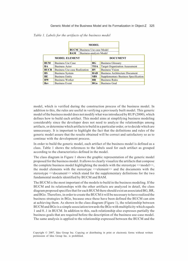
Generic Model of the Business Model and Its Formalization in Object-Z 325
Copyright © 2007, Idea Group Inc. Copying or distributing in print or electronic forms without writtenpermission of Idea Group Inc. is prohibited.
model, which is verified during the construction process of the business model. Inaddition to this, the rules are useful in verifying a previously built model. This genericmodel of the business model does not modify what was introduced by RUP (2000), whichdefines how to build each artifact. This model aims at simplifying business modelingconsiderably since the developer does not need to analyze the relationships amongartifacts, or determine which artifacts to build in a particular order, or to decide which areunnecessary. It is important to highlight the fact that the definitions and rules of thegeneric model assure that the results obtained will be correct and satisfactory so as tocontinue with the development process.In order to build the generic model, each artifact of the business model is defined as aclass. Table 1 shows the references to the labels used for each artifact as groupedaccording to the characteristics defined in the model.The class diagram in Figure 1 shows the graphic representation of the generic modelproposed for the business model. It allows to clearly visualize the artifacts that composethe complete business model highlighting the models with the stereotype <<model>>,the model elements with the stereotype <<element>> and the documents with thestereotype <<document>> which stand for the supplementary definitions for the twofundamental models identified by BUCM and BAM.The BUCM is the most important of the models to build in the business modeling. If theBUCM and its relationships with the other artifacts are analyzed in detail, the classdiagram proposed specifies that for each BUCM there should exist an associated BG, BR,and BGo. Therefore, in order to create the BUCM it will be necessary to have realized thebusiness strategies in BGo, because once these have been defined the BUCM can aimat achieving them. As shown in the class diagram (Figure 1), the relationship betweenBUCM and BGo is a simple association towards the BGo with multiplicity which equals1 and 0..1 in BUCM. In addition to this, such relationship also expresses partially thebusiness goals that are required before the description of the business use-case model.The same analysis is applied to the relationship expressed between the BUCM and the
MODEL
BUCM Business Use-case Model BAM Business-analysis Model
MODEL ELEMENT DOCUMENT
BUM Business Use Case BG Business Glossary BA Business Actor TOA Target Organization Assessment BUCR Business Use-case Realization BV Business Vision BS Business System BAD Business Architecture Document BE Business Entity SBS Supplementary Business Specification BW Business Worker BR Business Rules Bev Business Event BGo Business Goal
Table 1. Labels for the artifacts of the business model

326 Daniele, Martellotto, & Baum
Copyright © 2007, Idea Group Inc. Copying or distributing in print or electronic forms without writtenpermission of Idea Group Inc. is prohibited.
Figure 1. Generic model of the business model
BG and BR artifacts. Moreover, it is known that each one of these artifacts will evolvegradually with the building of the general model.Since the terms defined in the BG possess a unique textual description that has to berespected by every other element in the business model, this could be indicated in theclass diagram with a dependency relationship from each artifact to the BG. This is notdone to make clear the visualization of the diagram and this is textually expressed in oneof the rules.The model rules exist in any context that is studied and, therefore, it is visualized andspecified that the BR artifact must exist whenever a BUCM is built. This contributes animportant definition in the building of a solution where the developer is able to determinewhich artifacts must be defined in every business model. After this, depending on thecontext of the problem to be solved and the size of the business to be modeled, there aredocuments that supplement the BUCM and may be included or excluded from the generalmodel. These are expressed in the class diagram as BAD, SBS, BV, and TOA. The
Generic Model of the Business Model and Its Formalization in Object-Z 327
Copyright © 2007, Idea Group Inc. Copying or distributing in print or electronic forms without writtenpermission of Idea Group Inc. is prohibited.
relationship between each document and the BUCM is an association with 0..1 multiplic-ity and navigability to the document. To build these documents is not obligatory;however, if they are built they must be related to the BUCM of the general model.In addition to this, after observing the relations in the diagram between the BUCM andits BUC and BA components, a developer can infer that to build a BUCM the definitionof the BUC and BA must be taken into account. Besides, every BA must be associatedto at least one BUCNoAbstract and a BUCNoAbstract must be associated to at least oneBA.According to the definition provided by the RUP (2000), when the project team under-stands the business analysis, the BAM can be excluded. If this action is taken, it can beobserved that by excluding the BAM its associated components are excluded as well.This is due to the definition of the relations of composite aggregation or composition,where there is a strong ownership and coincident lifetime as part of the whole, in thisparticular case, between the BAM and the model elements BUCR, BE, BW, BEv and BS.In some cases, the BAM can be completely built or it can only be defined with the DomainModel that is formed with the business entities, BE. The class model proposed specifiesthat in order to realize the BAM one or more BE must be defined, that it is based on theBUCM and that the BR document as well as the BG can be used, revised and even updatedas the BAM evolves.The BAM is related to the BUCM given the fact that its purpose is to describe how theBUC are developed and executed. Therefore, a semantic relationship is shown to holdbetween both models indicating that the BAM uses the BUCM definition. A dependencyis a using relationship, specifying that a change in the specification of one thing (BUCM)may affect another thing that uses it (BAM), but not necessarily the reverse.Even though every business document has a purpose and is particularly important, thedocument that contains the business rules is the BR. It is an essentially important artifactbecause each rule defines a restriction or invariant that the business must satisfy andmaintain during the development of the project. There are behavioral and structuralrestrictions that affect the sequence of actions that define a BUC such as pre and postconditions that must be satisfied by the BUCR. When the domain model is built, it isgenerally represented with a UML class diagram which reflects the structural rules asrelations and/or multiplicity between the BE. In addition to this, the rules of the BR arealso associated with the BG because the maintenance of policies and conditions requireconstant revision of the terms defined in the BG.
Translation of theUML Class Diagram into Object-Z
Object-Z (Smith, 2000a) is an extension object oriented to Z (Spivey, 1989). It is a formalspecification language based on states in which the different states of a system, the initialstate and the operations, are modeled by schemes that involve a set of variabledeclarations associated to a predicate called class schema. Smith defines the specifica-
328 Daniele, Martellotto, & Baum
Copyright © 2007, Idea Group Inc. Copying or distributing in print or electronic forms without writtenpermission of Idea Group Inc. is prohibited.
tion of recursive structures in Object-Z. The type corresponding to a class schema is aset of identifiers that refer to objects of the class. That is, the objects they referencebehave according to the definitions in the class schema. The identifiers themselves,however, are independent of these definitions. This independence allows us to relax thenotion of “definition before use” of Z. This notion prevents, for example, a schema Sincluding a variable whose value is an instance of S. In Object-Z, however, a class maycontain a state variable that is an instance of the type defined by that class. Each classin Object-Z has an implicitly declared constant self that for a given object of the classdenotes that object’s identifier.A UML class diagram represents the generic model of the business model. UML is acommon language, easy to understand and apply, however, it lacks a precise semantics,which causes problems of ambiguities that in turn generate incorrect or differentinterpretations. Then, the generic model of the business model is translated into theformal specification language Object-Z, which allows the expression of a specificbusiness model in a particular domain without ambiguity, and also facilitates the analysisof the properties of the system, showing possible inconsistencies, ambiguities orincompleteness.For the translation of the UML class diagram into Object-Z expressions, the definitionsexposed in Roe et al. (2003), Becker and Pons (2003), and Kim and Carrington (1999, 2000)are considered and the following translation mechanism is defined:
• Firstly, BM is defined as a package that contains all the classes of the diagram.• Each class of the diagram is mapped into an Object-Z class, using the same class
label to which the BM, package name, is prefixed.• The associations among classes are expressed as attributes in the Object-Z class
created. An attribute, which is named after the opposite class, is added to the classwith a navigable association end. In addition to this, the type of the attribute willdepend on multiplicity, the relations with 0..1 multiplicity the type of the attributeis that of the opposite class, and when there is more than one, the type will berepresented as a set of elements belonging to the opposite class type. However,if both ends are navigable a restriction is added to indicate so.
• For the composition, the symbol © is added to each attribute which is a “part” ofthe whole in the compound class. In addition to this, a restriction is added toindicate that each “part” is also contained in the whole.
• The association class is represented as a class outline with an attribute for eachassociated class and a restriction that indicates that there is only one instance ofthe association class that belongs to an instance of the associated classes.
• In the generalization, the name of the parent class is added at the beginning of thechild’s class outline.

Generic Model of the Business Model and Its Formalization in Object-Z 329
Copyright © 2007, Idea Group Inc. Copying or distributing in print or electronic forms without writtenpermission of Idea Group Inc. is prohibited.
Formalization of the Generic Model of the Business Model
The BM is a “package” that groups every artifact out of which it is composed. In additionto this, three basic types are defined, namely, model, element and document, which allowto indicate the artifact that corresponds to each stereotype.Using the class diagram and using the translation mechanism described above, Object-Z expressions are built. Each class scheme that translates each artifact has an attributethat indicates the stereotype to which it is associated.The BG presents an association relationship with navigability in both ends of the BAMand the BUCM, therefore it contains two attributes, a restriction to indicate themultiplicity and a restriction that indicates navigability, both for each attribute. Figure2 shows the class scheme that represents the translation of the BG with each of itselements.
Figure 2. Class scheme of business glossary (BG)
Figure 3. Class scheme of business rules (BR)

330 Daniele, Martellotto, & Baum
Copyright © 2007, Idea Group Inc. Copying or distributing in print or electronic forms without writtenpermission of Idea Group Inc. is prohibited.
The BR document is associated to the BUCM, BAM, and BG. The latter relationship isonly navigable from the BR to the BG and not in the reverse direction; therefore, inaddition to the BUCM and BAM attributes, this class has a BG type attribute, threerestrictions that define multiplicity and three restrictions that define navigability. Figure3 shows the class scheme that translates the BR of the original class diagram.In the BUCM, there is an attribute for each one of the <<document>> classes and thereare two attributes to represent the BUC and BA type. These attributes are defined as aset of elements and they have the © to indicate that they are related to the whole, the
Figure 4. Class scheme of business use-case model (BUCM)
Figure 5. Class Scheme for Business Use Case (BUC)

Generic Model of the Business Model and Its Formalization in Object-Z 331
Copyright © 2007, Idea Group Inc. Copying or distributing in print or electronic forms without writtenpermission of Idea Group Inc. is prohibited.
BUCM. The multiplicity of each class is translated and two restrictions that indicate thecomposition relationship are added. Figure 4 shows the class scheme for this artifact.The BUC is part of the BUCM and, similar to the BA, has a restriction that indicates so.In addition to this, BUC is the parent class for BUCAbstract and BUCNoAbstract,therefore the class scheme that represents them indicates such a generalizationrelationship. See Figure 5.In the Figure 6 shows the class scheme for the artifact BA. More important is a restrictionindicating that there can be a relationship among the actors is also defined in BA.The BE element is part of the BAM model and part of the BS element. In addition, BE isassociated to the BUCR and BW. In the class scheme of the Figure 7 the restrictions aredefined that indicate these associations and their multiplicity.
Figure 6. Class scheme for business actor (BA)
Figure 7. Class scheme for business entity (BE)
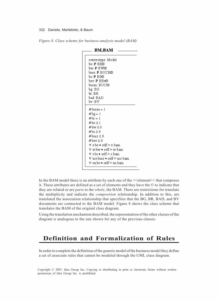
332 Daniele, Martellotto, & Baum
Copyright © 2007, Idea Group Inc. Copying or distributing in print or electronic forms without writtenpermission of Idea Group Inc. is prohibited.
In the BAM model there is an attribute by each one of the <<element>> that composesit. These attributes are defined as a set of elements and they have the © to indicate thatthey are related or are parts to the whole, the BAM. There are restrictions for translatethe multiplicity and indicate the composition relationship. In addition to this, aretranslated the association relationship that specifiies that the BG, BR, BAD, and BVdocuments are connected to the BAM model. Figure 8 shows the class scheme thattranslates the BAM of the original class diagram.Using the translation mechanism described, the representation of the other classes of thediagram is analogous to the one shown for any of the previous classes.
Definition and Formalization of Rules
In order to complete the definition of the generic model of the business model they definea set of associate rules that cannot be modeled through the UML class diagram.
Figure 8. Class scheme for business-analysis model (BAM)

Generic Model of the Business Model and Its Formalization in Object-Z 333
Copyright © 2007, Idea Group Inc. Copying or distributing in print or electronic forms without writtenpermission of Idea Group Inc. is prohibited.
The class diagram proposed plus the set of rules displayed in this section will help thesoftware engineer to verify that a concrete business model is built correctly from suchgeneric model, or to determine if a previously built business model complies with theserules and therefore it is the right one.The rules given below impose relations and conditions among the artifacts, however,without taking into account the conditions to be considered for the internal constructionof each artifact.The defined rules are grouped into general rules for the business model, rules that areassociated to the business use-case model and, finally, rules that correspond to thebusiness-analysis model. Each group is identified with the labels BM, BUCM, and BAM,followed by a correlative number.The rules defined in natural language and its formalization into Object-Z expressions areshows in the following tables.
• Rules defined for the business model (BM):
Natural Language Object-Z
(BM.1) BM={artifact} A BM is defined as a set of artifacts.
∀ bm: BM • bm: P artifact
(BM.2) Each artifact has only one instance for a particular BM.
∀ a: artifact, bm: BM • a ∈ bm ⇒ # a = 1
(BM.3) Every BM must have a BG, BGo, BR and BUCM.
∀ bm: BM • (∃ bg: BG, bgo: BGo, br: BR, bucm: BUCM • # bg = 1 ∧ # bgo = 1 ∧ # br = 1 ∧ # bucm = 1)
(BM.4) Each BG term must be included in the description of at least one BUC.
BG = {(term,description)} BUC = {(specification,description)} ∀ bg:BG, buc:BUC • (t ∈ dom bg ⇒ t ∈ ran buc)
• Rules defined for the business use-case model (BUCM) and its elements:
Natural Language Object-Z
(BUCM.1) A BUCAbstract is not related to any BA, therefore it will never be instantiated.
∀ buc: BUCAbstract, ba: BA • # buc.ba = 0
(BUCM.2) A BUC can relate to other BUC by means of include, extend, or generalization relations.
TR ::= include | extend | generalization ∀ buc1,buc2: BUC, tr:TR • (# buc1.buc2 > 0 ⇒ buc1.buc2 = tr) ∧ (# buc2.buc1>0 ⇒ buc2.buc1 = tr)
(BUCM.3) A BUC cannot be related to itself.
∀ buc1,buc2:BUC • # buc1.buc2 > 0 ∨ # buc2.buc1 > 0 ⇒ buc1 ≠ buc2
(BUCM.4) An BA cannot be related to itself. ∀ ba1,ba2:BA • # ba1.ba2 >0 ∨ # ba2.ba1 > 0 ⇒ ba1≠ba2

334 Daniele, Martellotto, & Baum
Copyright © 2007, Idea Group Inc. Copying or distributing in print or electronic forms without writtenpermission of Idea Group Inc. is prohibited.
• Rules defined for the business-analysis model (BAM) and its elements:
Natural Language Object-Z (BAM.1) An BE can be related to itself or to other BE. ∀ be1,be2: BE • # be1.be2 ≥ 0 ∧ # be2.be1 ≥ 0
(BAM.2) Each BW, BE and BEv must participate in at least one BUCR. ∀ bw:BW, be:BE, bev:BEv • (∃ bucr:BUCR • #
bw.bucr > 0 ∧ #be.bucr > 0 ∧ # bev.bucr > 0)
(BAM.3) Each BE must be documented in the BG.
BG = {(term,description)} ∀ e:BE; bg:BG • e ∈ Dom BG
Application of the Generic Modelto a Case Study
An example of application is given to show the capacity of the method proposed. Thisexample shows the relations built among artifacts such as BG, BGo, BR, BUCM, andBAM:BE. It is important to mention that according to the generic model and its rules theBUCM cannot be built in isolation for it needs the following artifacts to be created as well:BG, Bgo, and BR. Besides, in order to create the BAM or a part of it, it is necessary tohave created the BUCM. The generic model proposed imposes an order in the creationof some artifacts that need to be constantly revised during the process of constructionof the actual model.
Case Study: Credit Card Information Service
A hypothetical credit card company requires a business model for an information service.Since the information service works through the telephone the company has a phonenumber and a series of lines. The average number of daily calls is 150 and the companyprovides the information service from 9:00 am. to 5:00 pm, that is to say, 8 hours everyday. The highest demand for the service takes place from 10:00 am. to 1:00pm when anaverage of 60% of calls are produced. In an attempt to satisfy client’s demands, thecompany has arranged that from 9:00 to 10:00 and from 1:00 to 5:00 pm. there will only beone telephone operator, while there will be three during the hours of highest demand. Atelephone call proceeds as follows: a client calls, the telephone operator records thefollowing information in a call registration form: client’s full name, identity number, cardnumber, security code number — at the back of the card, a description of the call and thecode that corresponds to the call. The company has categorized the following reasonswhy clients call: card loss, Internet purchasing, movement and balance, due dates andpayments, promotions and travel assistance. At the beginning of his or her shift, theoperator opens the call registration form, and it is closed at the end. After this, the recordis filed with all the other call records.

Generic Model of the Business Model and Its Formalization in Object-Z 335
Copyright © 2007, Idea Group Inc. Copying or distributing in print or electronic forms without writtenpermission of Idea Group Inc. is prohibited.
Building the Business Model
In order to create a business model for a credit card information service, a BG has to bedefined followed by the BGo and the BR. Based on this, the BUCM is built and the BEare identified and grouped in a domain model which corresponds to the BAM.The different steps are described in detail below:
1. First, the problem to be solved is carefully analyzed and the most important termsfor the business are defined. Each term will be described within a text that will beconsidered all along the project. These terms will be redefined as the other artifactsare built, and they represent an instance of the artifact BG in the generic model.Then, the BG instance is:• Artifact: BG:
� Line: telephone line used by the client to consult the operator.� Call: action performed by the client to contact and consult an operator.
Each call corresponds to a specified reason.� Reason: what causes the consultation. The reasons are categorized as
follows: credit card loss, Internet purchasing, movement and balance,due dates and payments, promotions and travel assistance.
� Operator: person assigned to answer incoming calls.� Client: person who holds one of this company’s credit cards and uses
the service to consult the company.� Form: it is a sheet with five columns to record the following information
about the client: Surname and Name, identity number, card number,security code, and the code specified for the call.
2. Second, the business goals are defined and they turn the business strategies intoconcrete and measurable strategies. In this example, a business goal is defined anddocumented in BGo.
• Artifact: BGo:� Name of the objective: always replying an incoming call.� Description: every time a client makes a call, the company must handle
it by answering the caller’s questions provided it has been previouslycategorized.
3. Third, the business policies determine the business operation and control. Thefollowing is a list of each rule in natural language.
• Artifact: BR:a. There must always be at least one phone line and an operator available.b. An operator can answer any phone line in any of his or her shifts.c. A client can call as many times as she or he wishes to consult an operator.

336 Daniele, Martellotto, & Baum
Copyright © 2007, Idea Group Inc. Copying or distributing in print or electronic forms without writtenpermission of Idea Group Inc. is prohibited.
d. Each call is associated to a single reason.e. A call is answered in only one line.f. If the company does not categorize the reason expressed by the client,
then the information exchanged must not be recorded.g. If the call corresponds to a reason categorized by the company then it
must be recorded in a form.h. A call registration form must be opened and closed by the same operator.
4. The following step is to identify and describe the business use cases and actorsthat constitute the business use-case model. In the example, we concentrate on theuse case “Consultation” and informally describe pre and post conditions, actorsinvolved, and events flow. Both business actors, operator and client, are definedas terms in the BG. The following UML diagram models business use case definedand the actors proposed.
• Artifact: BUCM:
Business use case diagram Client
Consultation Operator
• Textual description of the artifact BUC: ConsultationA client calls the company, the operator answers the call and asks for thefollowing information: client’s full name, identity number, card number,security code number, a description of the call and records the reason thatcorresponds to the call. The operator records the information in a callregistration file. If the call does not correpond to one of the categoriesconsidered by the company, the information is not recorded. Finally, theoperator either satisfies the client’s requests or not and ends the call.
Business Use Case: Consultation Business Actors: Operator and Client Precondition: there is one available line and operator during client assistance hours. Actions: 1. The client makes a phone call. 2. The operator answers the call and records the following information in a form: full name, identity number, card number, security code, reason, and description for the consultation. 3. The operator provides the information required. 4. The operator ends the call. Alternative path: 2.1. If the reason for the call does not fit to one of the categories considered by the company, the call is not recorded and communication is ended. Postcondition: the client’s purpose has been satisfactorily achieved or the purpose for the call is not categorized and therefore it is disregarded.
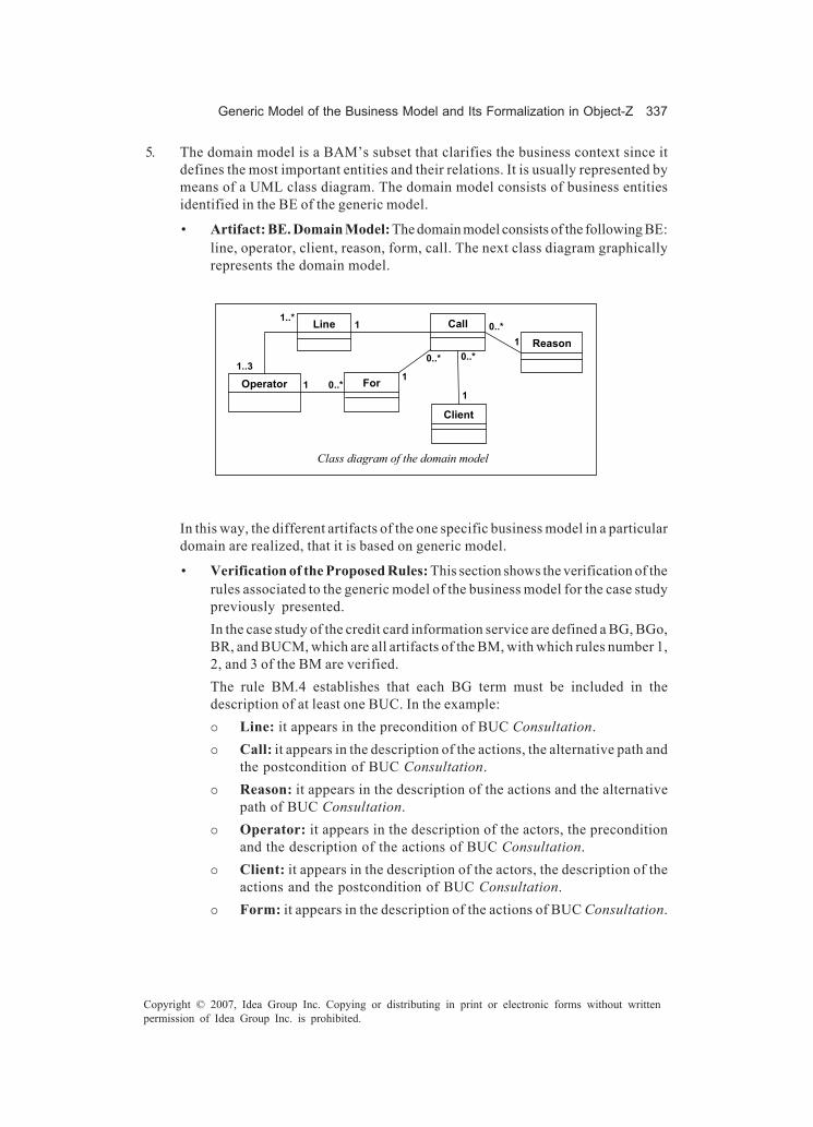
Generic Model of the Business Model and Its Formalization in Object-Z 337
Copyright © 2007, Idea Group Inc. Copying or distributing in print or electronic forms without writtenpermission of Idea Group Inc. is prohibited.
5. The domain model is a BAM’s subset that clarifies the business context since itdefines the most important entities and their relations. It is usually represented bymeans of a UML class diagram. The domain model consists of business entitiesidentified in the BE of the generic model.
• Artifact: BE. Domain Model: The domain model consists of the following BE:line, operator, client, reason, form, call. The next class diagram graphicallyrepresents the domain model.
Class diagram of the domain model
Line Call
Reason
Operator For
Client
1..*
0..* 0..*
0..*
0..*
1..3
1 1
1
1
1
In this way, the different artifacts of the one specific business model in a particulardomain are realized, that it is based on generic model.
• Verification of the Proposed Rules: This section shows the verification of therules associated to the generic model of the business model for the case studypreviously presented.In the case study of the credit card information service are defined a BG, BGo,BR, and BUCM, which are all artifacts of the BM, with which rules number 1,2, and 3 of the BM are verified.The rule BM.4 establishes that each BG term must be included in thedescription of at least one BUC. In the example:� Line: it appears in the precondition of BUC Consultation.� Call: it appears in the description of the actions, the alternative path and
the postcondition of BUC Consultation.� Reason: it appears in the description of the actions and the alternative
path of BUC Consultation.� Operator: it appears in the description of the actors, the precondition
and the description of the actions of BUC Consultation.� Client: it appears in the description of the actors, the description of the
actions and the postcondition of BUC Consultation.� Form: it appears in the description of the actions of BUC Consultation.

338 Daniele, Martellotto, & Baum
Copyright © 2007, Idea Group Inc. Copying or distributing in print or electronic forms without writtenpermission of Idea Group Inc. is prohibited.
The rule BUCM.1 is not applied in this example, since any BUCAbstract hasnot been defined.On the other hand, the rules number 2 and 3 of the BUCM either cannot beapplied since a single BUC has been defined. The defined BA are Operator andClient, and no is related to itself, with which it is verified the rule BUCM.4 (seebusiness use case diagram).Respect to the rules of the BAM, the rule BAM.1 is verified since no BE isrelated to itself or to another BE (see class diagram of the domain model).The artifacts BUCR, BW, and BEv have not been modeled in the example, bythis, rule number 2 cannot be applied.Finally, the BEs defined are line, operator, client, reason, form and call,which appear in the BG, with which verifies the rule BAM.3.In this way, all it applicable rules in the case study have been verified.
Conclusion
This chapter shows the definition of a generic model of the business model, expressedby means of a UML class diagram, together with a set of rules expressed in naturallanguage. This model and their rules are translated into a formal specification languagelike Object-Z through a translation mechanism defined.This formalization of the generic model is now a well-formed reconstruction of the originalmodel presented by RUP that allows to visualize and specify not only the artifacts thatcompose the business model in a complete and organized way but also the relationshipsholding among them. In addition to this, this formalization expresses precisely therestrictions associated to these artifacts that stem from the UML class diagram of thegeneric model as well as from the general rules of the model. Moreover, it provides aconsistent association among the generic model (expressed in UML class diagram), itsassociated rules (expressed in natural language), and the translation of both intoObject-Z.In this way, the graphic representation of the business model by means of only one classdiagram that shows every artifact that composes this model as well as the relationshipsamong them, simplifies the problem of business modeling. Moreover, the formalizationof the model allows one to verify its correctness precisely and rigorously during theconstruction process or during the process of revision of a previously built model.
References
Baum, G., Daniele, M., Martellotto, P., & Novaira, M. (2004). Un modelo genérico para elmodelo de negocio. X Congreso Argentino de Ciencias de la Computación,
Generic Model of the Business Model and Its Formalization in Object-Z 339
Copyright © 2007, Idea Group Inc. Copying or distributing in print or electronic forms without writtenpermission of Idea Group Inc. is prohibited.
CACIC2004. Workshop de Ingeniería de Software y Base de Datos (WISBD) (pp.509-519). Universidad Nacional de La Matanza.
Becker, V., & Pons, C. (2003). Definición formal de la semántica de UML-OCL a través desu traducción a Object-Z. CACIC 2003. Workshop de Ingeniería de Software yBase de Datos (WISBD) (pp. 977-989). Universidad Nacional de la Plata.
Booch, G., Rumbaugh, J., & Jacobson, I. (1999). The unified modelinglanguage: Userguide. Addison Wesley.
Eriksson, H. E., & Penker, M. (2000). Business modeling with UML. In Business patternsat work. John Wiley & Sons.
Jacobson, I., Booch, G., & Rumbaugh, J. (1999). The unified software developmentprocess. Addison Wesley.
Kim, S. K., & Carrington, D. (1999). Formalising the UML class diagram using Object-Z.In Proceedings of the 2nd International Conference on Unified Modelling Lan-guage (UML’99) (LNCS 1732). Springer-Verlag.
Kim, S. K., & Carrington, D. (2000). A formal mapping between UML models and Object-Z specifications. In Proceedings of ZB2000: International Conference of B andZ Users (LNCS 1878).
Kim, S. K., & Carrington, D. (2004, April). A formal object-oriented approach to definingconsistency constraints for UML models. In Proceedings of the AustralianSoftware Engineering Conference (ASWEC 2004), Melbourne, Australia: IEEEComputing Society.
Moura, P., Borges, R., & Mota, A. (2003, October 12-14). Experimenting formal methodsthrough UML. Presented at the VI Brazilian Workshop on Formal Methods,Campina Grande, Brazil.
Object Management Group (OMG). (2001). Unified Modeling Language specification,version 1.3, ad/00-03-01.
Ortín, M., García Molina, J., Moros, B., & Nicolás J. (2001). El modelo del negocio comobase del modelo de requisitos. In Jornadas de Ingeniería de Requisitos Aplicada.Spain: Facultad de Informática de Sevilla.
Rational unified process (RUP). (2000). Retrieved from http://www.rational.com/rup/Roe, D., Broda, K., & Russo, A. (2003). Mapping UML models incorporating OCL
constraints into Object-Z. (Tech. Rep. No. 2003/9). London: Imperial College.Salm, J. F. (2003). Extensões da UML para descrever processos de negócio. Dissertação
(Mestrado em Engenharia de Produção), Universidade Federal de Santa Catarina,Florianópolis.
Sinogas, P., Vasconcelos, A., Caetano, A., Neves, J., Mendes, R., & Tribolet, J. (2001, July7-10). Business processes extensions to UML profile for business modeling. InProceedings of the 3rd International Conference on Enterprise InformationSystems, Setubal, Portugal (Vol. 2).
Smith, G. (1992). An object oriented approach to formal specification. Thesis for thedegree of Doctor of Philosophy. Australia: The Department of Computer Science,University of Queensland.

340 Daniele, Martellotto, & Baum
Copyright © 2007, Idea Group Inc. Copying or distributing in print or electronic forms without writtenpermission of Idea Group Inc. is prohibited.
Smith, G. (2000a). The Object-Z specification language: Advances in formal methods.Kluwer Academic Publishers,.
Smith, G. (2000b). Recursive schema definitions in Object-Z. In J. P. Bowen, S. Dunne,A. Galloway, & S. King (Eds.), 1st International Conference of Z and B Users (ZB2000) (LNCS 1878, pp. 42-58). Springer-Verlag.
Spivey, J. M. (1992). The Z notation: A reference manual (2nd ed.). Prentice Hall.UML 2.0. (2003). OMG Adopted Specification, ptc/03-09-15. Object Management
Group.

Efficient Software Quality Assurance Approaches 341
Copyright © 2007, Idea Group Inc. Copying or distributing in print or electronic forms without writtenpermission of Idea Group Inc. is prohibited.
Chapter XIII
Efficient SoftwareQuality Assurance
Approaches Orientedto UML Models
in Real LifeLuis Fernández, Universidad Europea de Madrid, Spain
Pedro J. Lara, Universidad Europea de Madrid, Spain
Juan José Cuadrado, Universidad de Alcalá, Spain
Abstract
UML is accepted as the standard notation for object-oriented (OO) development. UMLmodels have a widespread use in today’s software practices. Any initiative to improvesoftware quality assurance (SQA) should assume that a high percentage of deliverablesto be controlled are currently based on the use of UML notation. However, real lifeprojects are strongly influenced by the need of reaching tangible productivity andefficiency goals. SQA techniques should be customized to meet the balance betweenquality and budget supported by risk analysis. In this chapter, different strategies andtechniques devised to follow the above philosophy of efficiency are presented, especiallycentred in automatic testing generation from specifications. Our proposal is mainly

342 Fernández, Lara, & Cuadrado
Copyright © 2007, Idea Group Inc. Copying or distributing in print or electronic forms without writtenpermission of Idea Group Inc. is prohibited.
based on a recommended course of action as well as on integrated tool support forEclipse environments.
Introduction
As defined by ISO (2000a), quality is defined as “the ability of a set of inherentcharacteristics of a product, system, or process to fulfil requirements of customers andother interested parties.” In the case of software development and maintenance, qualitycan be promoted by actions in three different axes:
1. Selection, recruiting, training, and motivation of the best human resources forthe development team: Good developers tend to produce good software andsometimes there are “Net negative producing programmers” who do not producebut also reduce productivity of the rest of the team (Schulmeyer, 1992). Models likePSP (Humphrey, 1996) and TSP help to set individual performance apart from otherconsiderations of degree or educational curricula for IT professionals (Fernández& García, 2003).
2. Best practices and organization for development processes acting as frameworksfor exploiting the benefits of the two other axes: Models like ISO 9001 (ISO, 2000a),CMMi (Chrissis, Konrad, & Shrum, 2003) or ISO 15504 SPICE (series of standardsstarting with ISO, (2004)) provide a framework for evaluating, improving, andcertifying best practices related to software processes.
3. Improvement of development methods, techniques, tools, and technology: What itis assumed is that better resources lead to better characteristics of the producedsoftware. This is not only applicable to development methods that prevent theinsertion of defects and get better designs or code (e.g., use of new compilers,environments or even notations like UML, etc.) but also to all the activities forcontrolling results and detecting and fixing problems before customers begin touse the software (e.g., inspections, testing tools, etc.). Obviously, technologymarkets tend to use exaggerated expectations and promises to enhance capabilitiesof products that have been reported with interesting data in references likeMcConnell (1996) or Jones (1994).
In this chapter, we will explore different possibilities of improving and making moreefficient the methods and techniques for preventing and detecting defects for real-lifepractitioners following a philosophy of SQA defined as a “planned and systematicpattern of all actions necessary to provide adequate confidence that the item or productconforms to established technical requirements” (IEEE, 1991).One of the problems is that today’s software development market rules do not favour areal competition between providers based on offering high quality as the primaryreasoning of their strategy because projects are still mainly driven by schedule andbudget stringent schemes. This market is not mature enough to have a customer culture

Efficient Software Quality Assurance Approaches 343
Copyright © 2007, Idea Group Inc. Copying or distributing in print or electronic forms without writtenpermission of Idea Group Inc. is prohibited.
with a clear concept of what it is really software quality and how to evaluate it. Althoughthe triangle principle is conceptually assumed for projects (see Figure 1), as McConnell(1996) explains there are still many occasions where it is not practised (at least 40% oftimes, simultaneous restrictions along the three axis are imposed).In this market environment, managers need a dramatic improvement of efficiency and costreduction in order to have enough arguments to bet on real implementation of SQAtechniques in the projects. Obviously there are conspicuous initiatives to promote highlevel (organizational perspective) models for improving results following the above workline 2: executive staff is likely more interested in this top-down schemes than in moredetailed actions simply because they are more understandable for them. It is clear thata huge amount of effort has been devoted to quality management systems (e.g., basedon ISO 9001) but mainly due to marketing reasons (e.g., ISO certificates offer a good imageof the organizations) or customer dispositions (e.g., ISO certificated organizations tendto demand certification of providers). As explained before, CMMi and SPICE offer a goodnumber of studies that supports, at first sight, benefits of increasing productivity andreducing risks.In this chapter, we are more concerned in offering more detailed ways to softwarepractitioners (a guerrilla approach) to improve efficiency in SQA implementation withcommon techniques like testing, metrics and review processes like inspections. Tounderstand all the implications of this approach, we should pay attention to the followingfacts:
• There are no techniques that enable developers or SQA personnel to verify theabsence of defects in the software products. For example, no feasible testingprocedure has been devised. As Dikjstra has stated: “Testing cannot guarantee the
Figure 1. The triangle principle for software projects: for example, fewer budgetsshould be balanced by an increment in time and/or defects to preserve area size
Time Defects Constant
area Budget
Budget
Time Defects Constant area

344 Fernández, Lara, & Cuadrado
Copyright © 2007, Idea Group Inc. Copying or distributing in print or electronic forms without writtenpermission of Idea Group Inc. is prohibited.
Figure 2. SQA as a series of hurdles for the software “athlete”
Specification review
Software testing
Code inspection
Design review
Confidence
��������
No exhaustive test or controls
Rentabilidad económica
Rentabilidad económica
Specification review
Software testing
Code inspection
Design review
Confidence
��������
No exhaustive test or controls
Rentabilidad económica
Rentabilidad económica
absence of defects; it can only demonstrate that they exist in the software.” It iscommon to conceive SQA controls (following the definitions and philosophy ofISO (2000a) like the different hurdles of an athletics competition (see Figure 2). Eachof them is not so high an obstacle that demonstrates the value of the software butthe whole series of controls lets us have a good degree of confidence that softwaremeets expectations.
• Any initiative to improve SQA should assume that a high percentage of deliverablesto be controlled are currently based on the use of UML notation. If SQA methodsforce developers to have a dual set of models or documents, they will rejectfollowing the control procedures because they cannot (and do not like to) affordextra efforts. Efficient approaches try to integrate tools and models in the sameenvironment to avoid additional management and translation activity. Trends likeintegration through the lifecycle of models (e.g., RUP, MDA, etc.) or tools (e.g.,complete vendor solution integrating CASE-model tools with configuration man-agement, metrics, and other complimentary facilities). Developers tend to bereluctant to follow methodology or notational guides (although their benefits havebeen proven repeatedly). They want to see that their effort in this area lead toadditional benefits: for example, saving future efforts in quality control activitieslike, for example, testing design and execution or, especially, code generation likein the model-driven (MDA or MDSD) paradigm. Indeed, a high percentage ofdevelopers suffer from a deficient training on software testing and SQA tech-niques, and small- and medium-sized companies are not prepared for a correctimplementation of SQA approaches. We have detected this in several surveysdeveloped within the Software Quality Group of ATI (the National SpanishProfessional Association, http://www.ati.es) and with 1994 data from QAI (http://www.qaiusa.com).

Efficient Software Quality Assurance Approaches 345
Copyright © 2007, Idea Group Inc. Copying or distributing in print or electronic forms without writtenpermission of Idea Group Inc. is prohibited.
• A great variety of experiments and data collection experiences have revealed thatbest results in defect detection are achieved when a proper combination oftechniques (both static and dynamic) is deployed throughout the life cycle.Different authors have observed how reviewing processes (e.g., inspections,formal technique reviews, etc.) are more appropriate to find out certain kinds ofdefects (that constitutes an specific percentage of the total number) and howtesting are more suitable to detect other types of “bugs”. Moreover, SQA shouldbe established in a life cycle basis to allow an early detection scheme with cleareconomic benefits, for example, cost of defect repair rises exponentially as theproject advances up to 1:60 rates from specification to system testing (a goodcompilation of these benefits could be found in Pressman (2003)).
• It is more difficult to reach highest levels of efficacy and efficiency of the main SQAtechniques (e.g., the ones recommended by IEEE std. 730 (IEEE, 1998) and 1074(IEEE, 1997) like testing, reviewing techniques, software measurement, etc.) if thereis not a good definition and standardization of the project deliverables where theyapplied to. An adequate formalization and definition of documents and models tobe produced in each project is as important as designing the best scheme of controlactivities. This is an implicit consequence of process improvement models likeCMMi: certain control techniques are not feasible to be applied before processeshave not reached a minimum degree of definition and formalization. One clearexample is testing: it is impossible to have good results if there is not a properrequirements management because tests should be based on descriptions of whatit is the expected behaviour of the program for each type of input action.
• Finally, nowadays conditions of actual development projects are so stringent inbudget and schedule that productivity is necessary for software organisations.Obviously, processes, methodology, and notation are not feasible without theproper support of tools and integrated automation of activities. One importantpoint is that requirements volatility and in-process modifications of softwaremodels during projects are a common issue, so developers need a change in UMLmodels. This could be rapidly translated into changes in the SQA activities. Fforexample, techniques that can enable a change in the software requirementsspecification can be directly and easily inserted into the corresponding accep-tance-test specification. Another important aspect is the need to establish apriority of software requirements and test cases because project leaders shouldhave mechanisms to deal with delays and risks as they appear (e.g., it is not possibleto complete the execution of the whole set of test cases before the ending date.Most important cases related to most important requirements and most frequentfunctions should be addressed first).
Background
As a starting point, we will present different recommendations related to SQA approachwhere the use of UML is intended under the perspective of the above assumptions.

346 Fernández, Lara, & Cuadrado
Copyright © 2007, Idea Group Inc. Copying or distributing in print or electronic forms without writtenpermission of Idea Group Inc. is prohibited.
Considering the classical phases of software life cycle, first point to be considered is test-case generation from software specification based on use cases and complimentarydiagrams. These diagrams are considered as a first milestone and a result of therequirements capture (or analysis and specification) phase. Obviously, one importantprevious point is to assure that use-case models and descriptions are verified andvalidated using different SQA techniques like inspections and checklists. These controlsare designed to support traditional techniques like reviewing processes to allow acheaper implementation of these V&V actions and will be treated in the second part ofthis section. Finally, a revision of tools combining risk analysis, testing-completioncriteria, coverage analysis, and test environments will be briefly described.
Test-Case Generation from Use Cases
In a software-development project, use cases are normally used to define systemsoftware requirements. Use-case modelling begins with the first steps of the project soreal use cases for key product functionality are available in early iterations of thelifecycle. According to UML, a use case “ ... fully describes a sequence of actionsperformed by a system to provide an observable result of value to a person or anothersystem using the product under development” (Booch, Rumbaugh, & Jacobson, 1998).Use cases tell the customer what to expect, the developer what to code, the technicalwriter what to document, and, the most important thing for us, the tester what to test.Obviously, many approaches have been devised to diminish the impact of possibleproblems and to prevent errors and miscommunications during the initial phases of aproject. Nowadays, it is generally accepted that good practices include the use of well-
Scenario Name Starting Flow Alternative Flow Scenario 1 — Successful registration Basic Flow Scenario 2 — Unidentified user Basic Flow A1 Scenario 3 — User cancels Basic Flow A2 Scenario 4 — etc. Basic Flow A3
Table 1. Scenario matrix
Test-case ID Scenario User ID Password Expected Result RC 1 Scenario 1 — successful
registration Valid Valid User enter the
system RC2 Scenario 2 — Unidentified
user Invalid N/A Error: Back to
login screen RC3 Scenario 2 — Unidentified
user Valid Invalid Error: Back to
login screen RC4 Scenario 2 — Valid User
Cancels Valid Valid Login screen
appears.
Table 2. Requirements and scenario analysis table
Efficient Software Quality Assurance Approaches 347
Copyright © 2007, Idea Group Inc. Copying or distributing in print or electronic forms without writtenpermission of Idea Group Inc. is prohibited.
known notation guides such as UML (Booch, Rumbaugh, & Jacobson, 1998) and theapplication of modern software processes like unified process (Jacobson, Booch, &Rumbaugh, 1999). These and other best practices have enabled developers to abatetraditional problems related to the functional requirements definition.Software testing includes many interrelated tasks, each with its own artefacts anddeliverables. Generation of test cases is the first fundamental step; test procedures aredesigned for those cases and, finally, test scripts are created to implement the proce-dures. Test cases are key products for the process because they identify and commu-nicate the conditions that will be implemented for testing. They are necessary to verifyand validate successful and acceptable implementation of the product requirements.Although few developers actually do it, project teams should create test cases as soonas use cases are available, no matter if any code is written (as agile methodologies likeExtreme Programming also recommend to do). Different approaches are available forgenerating test cases from use cases, although, as discussed in the section “Generationfrom Nonformal Specifications of Use Cases”, they present different shortcomings in ouropinion so we present our own proposal for test design in the section “A SQA Processfor Efficiency Supported by an integrated tool environment”.
Generation from Nonformal Specifications of Use Cases
A test case is considered as a set of test inputs, execution conditions, and expectedresults developed for a particular objective: to exercise a particular program path or verifycompliance, for example, with a specific requirement. From this definition, a typicalmethod (Heumann, 2002) to develop test cases from a fully detailed use case is thefollowing:
1. For each use case, we should generate a full set of use-case scenarios: Read theuse-case textual description and identify each combination of main and alternateflows (scenarios). This is documented using a scenario matrix (Table 1 shows apartial scenario matrix for a sample registration use case with no nested alternateflows).
2. Identification of test cases: This can be done by analyzing the scenarios andreviewing the use-case textual description as well. There should be at least onetest case for each scenario, but there will probably be more (see RC2-RC4 testcases). Boundary conditions should be added. Conditions or data elementsrequired to execute the various scenarios should be identified (Table 2 shows theresults for the explained registration use case: no data values have been actuallyentered).
3. Identification of data values for tests: Test cases should be reviewed and validatedto ensure accuracy and to identify redundant or missing test cases. Finally, actualdata values should be used to substitute Is and Vs.
Main advantage of this method is simplicity and direct application; absence of a formalrepresentation of use cases reduces automation capability and efficiency of the process.

348 Fernández, Lara, & Cuadrado
Copyright © 2007, Idea Group Inc. Copying or distributing in print or electronic forms without writtenpermission of Idea Group Inc. is prohibited.
Scenario-Based Test Generation
SCENT, a method for SCENario-Based Validation and Test of Software (Ryser & Glinz,2003) is similar to the previous method but based on scenarios of use cases and with aformal notation as basis for the process. It assumes that scenarios elicit and documentrequirements, functionality, and behaviour of a system so they help to discoverambiguities, contradictions, omissions and vagueness in natural language descriptionsby formalizing narrative scenarios with state charts (Harel, 1988). If state charts (wherenecessary and helpful) with pre and postconditions, data ranges and values, andperformance requirements, complement the information of use cases, we can systemati-cally derive test cases for system test by traversing paths in the state charts, choosingan appropriate testing strategy.The SCENT method includes the following phases: scenario creation, scenario formal-ization, and test-case derivation.
• Scenario creation: Table 3 shows the fifteen steps of this procedure.• Scenario formalization and annotation: The process includes two steps that
transform the scenario in a state-chart representation (formalization) and extendsthe diagram to include important information for testing, such as preconditions,data, and other nonfunctional requirements (annotation).
• Test-case derivation: Test-case derivation in the SCENT method comprises threesubsteps:
# Step Description 1. Find all actors (roles played by persons/external systems) interacting with the system 2. Find all (relevant system external) events 3. Determine inputs, results and output of the system 4. Determine system boundaries 5. Create coarse overview scenarios (instance or type scenarios on business process or task level) 6. Prioritize scenarios according to importance, assure that the scenarios cover system functionality 7. Create a step-by-step description of events and actions for each scenario (task level) 8. Create an overview diagram and a dependency chart (see “Integrated Tool Support for the Process”) 9. Have users review and comment on the scenarios and diagrams
10. Extend scenarios by refining the scenario description, break down tasks to single working steps 11. Model alternative flows of actions, specify exceptions and how to react to exceptions 12. Factor out abstract scenarios (sequences of interactions appearing in more than one scenario) 13. Include nonfunctional (performance) requirements and qualities in scenarios 14. Revise the overview diagram and dependency chart 15. Have users check and validate the scenarios (Formal reviews)
Table 3. Steps to create a scenario
Efficient Software Quality Assurance Approaches 349
Copyright © 2007, Idea Group Inc. Copying or distributing in print or electronic forms without writtenpermission of Idea Group Inc. is prohibited.
� Step 1 (mandatory): Test-case derivation from statecharts.
� Step 2 (mandatory): Testing dependencies among scenarios and additionaltests (e.g., testing for specific characteristics).
� Step 3 (optional): State-chart integration and test-case derivation from theintegrated statechart.
In SCENT, test cases are derived by path traversal in state charts. First, the normal flowof actions represented in the state chart is followed, and then the paths representing thealternative flows of actions and the exceptions are covered. In the method, all nodes andall links in the graph should be “executed,” that is, every state and every transition iscovered by at least one test case.Most states and many transitions are usually traversed more than once due to the useof the annotations to refine test cases. Preconditions to state charts define testpreparation that has to be done before test cases derived from the state chart can beexecuted. The data specified in the scenarios and annotated in the state charts helpdevelop boundary value tests. Domain-testing techniques and data-flow testing can beapplied to derive further test cases (Beizer, 1990, 1995; Myers, 1979). Furthermore, as pathtraversal in state charts will only generate tests for valid sequences of events, the testerhas to ensure inclusion of invalid event sequences in the test. These tests are con-structed by evoking or generating events while the machine is in a state where it shouldnot respond to the generated events. Thus, exception testing can be improved andsystematized and a better test coverage can be achieved. Notes on performance andnonfunctional requirements in the scenarios help to generate test cases to test theseproperties.A new diagram type called dependency charts (that include timing, logical and causaldependencies between scenarios) for supporting the second step of the method isdefined in SCENT. Although the method has been yet applied with good results, the effortneeded to implement it makes difficult a standard use.
Statistical-Based Test Generation
Based on usage or reliability tests, the main idea is to find those parts of the system thatdo not need to be tested so deeply because they are less important or frequent. Statisticaltests try to identify the 10% of the code that consume the 90% of the runtime. The methodallows the systematic transformation of a use-case model of a software system into ausage model (Walton, Poore, & Trammel, 1995). The usage model serves as input forautomated statistical testing.A software “usage model” characterizes intended use of the software in the intendedenvironment, that is, the population from which a statistically correct sample of test caseswill be drawn (Walton et al., 1995). Usage models resemble finite state machines withtransitions weighted with probabilities. The resulting model typically is a Markov chain(although other notations, such as graphs and formal grammars, can be used alterna-tively) describing the state of usage rather than the state of the system.

350 Fernández, Lara, & Cuadrado
Copyright © 2007, Idea Group Inc. Copying or distributing in print or electronic forms without writtenpermission of Idea Group Inc. is prohibited.
Typically, the process proposed consists of five main steps:
1. Use-case refinement
2. Use-case transformation into state diagrams: The result of this step is a hierarchyof state diagrams and a higher degree of formalization. Separate usage models canbe created per state diagram, allowing testing application at component rather thansystem level.
3. State diagrams transformation into usage graphs: A usage graph has a single startand a single final state. Transitions between states are labelled with the user actioncausing the transition to be taken.
4. Usage graphs transformation into usage models: There is no general systematicapproach for deriving these models. The probability of some outgoing transitionof a usage state may depend on previous execution of the system. This violates theusage model’s Markov property: solution relies on the replication and connectionof that state and its dependent states to assure that historic dependencies aresolved and, eventually, all of the usage graph’s states invocation probabilitiesdepend only on the immediately preceding state of the diagram.
5. Usage models transformation into test cases: Random testing is applied assuringthat minimal arrow coverage is reached before truly random test cases are gener-ated.
State-Driven Test Generation
All software can be modelled as a state machine. Usually, this method has been appliedto communication systems, but in OO development, the state machine is a natural wayof describing the status of system or objects. State-driven test generation concentrateson validating the correct sequencing of program actions and intermediate states.Different actions and state combinations, that is, paths through the program, are tested(as a whole or partially). A fault in the program may result in a wrong action that leadsit to a nonexpected program state. State-driven testing is also used to detect deadlocks.Following this idea, Kangasluoma (2000) describes an algorithm based on selecting pathsor segments to be tested within the state diagram and allocating a test case to eachtransition although this ignores how effects may depend on previous transitions. Toovercome this shortage, other proposals, for example, Offutt and Abdurazik (1999),suggest covering all predicates in each transition’s guard conditions to assure that theyrepresent all the intended effects.In the case of AGEDIS, the basis of the method is a model of the software applicationwritten in a modelling language, specifically designed to enable the automated testgeneration. The AGEDIS test methodology is based on an iterative process that can bedivided into six steps:

Efficient Software Quality Assurance Approaches 351
Copyright © 2007, Idea Group Inc. Copying or distributing in print or electronic forms without writtenpermission of Idea Group Inc. is prohibited.
1. A behavioural model of the system under test is built. Originally, it is based on classdiagrams with a state chart of the behaviour of objects in each class and objectdiagrams that describe the initial state of the system under test. UML use cases canbe used for this model because a state diagram of the use-case behaviour can beused for it.
2. Testing objectives (coverage goals, specific use cases, etc.) and testing architec-ture (deployment details) is translated into a set of test generation and testexecution directives.
3. An automatic test generator generates a test suite, satisfying the testing objectivesstated in the previous step.
4. The behavioural model, the test directives, and the test suites are reviewed bydevelopers, architects, and final users using specific tools for visualizing andanimating these artefacts.
5. Test suites are automatically executed and the test execution environment logs theresults.
6. Steps 2 to 5 are iterated until the desired coverage and quality objectives have beenreached.
Not all software may be treated by the AGEDIS tools; even for those applications thatfit the AGEDIS profile, not all test cases can be generated and executed automatically.
Test Generation Based on Path Analysis Techniques
Each use-case path is derived from a possible combination of following use-caseelements: basic flow, alternate flows, exception flows and extends and include relation-ships. Each path through a use case is a potential test case.The path analysis process consists of following four major steps (Ahlowalia, 2002):
1. Drawing a flow diagram (or activity diagram) for each use case: Each noderepresents the point where flow diverges or converges: several branches (orconnections between two nodes) are present. Each use case has only one start andcan have multiple ending points. Normally people tend to begin to construct thediagram by drawing the basic (happy day) flow and extending it to represent therest of the necessary behaviour.
2. Determining all possible paths: Beginning from the starting point each time, weshould list all possible ways to reach an ending node, keeping the direction of flowin mind. In some complex use cases, especially when there are many feedbackbranches, there could potentially be a very large number of paths. The aim here isto list all these paths. Each path can be named with an id like P1, P2 and so on, witha sequence of numbers of branches traversed (e.g., 2,3,4,5,…) and a textualdescription of the complete sequence of user actions and system responses takingplace along the path (in fact, a description of the test case itself).
352 Fernández, Lara, & Cuadrado
Copyright © 2007, Idea Group Inc. Copying or distributing in print or electronic forms without writtenpermission of Idea Group Inc. is prohibited.
3. Once a valid set of paths is generated, an analysis process leads to a priorityallocation to each path based on frequency and risk of its execution.
4. Most important paths are selected: to discover as much defects as possible witha minimum cost of execution.
Review Processes
As stated, SQA experiences have revealed that defect detection rates are dramaticallyincreased when testing and review processes are combined. Besides, early controls (atleast, at the end of each development phase as recommended in process standards) avoidincurring additional costs when defects remain unfixed phase after phase. When noexecutable deliverables are available, defect detection should rely on review processes.There is a huge amount of evidences of benefits obtained from the inclusion of reviewingcontrols, especially when inspections are the chosen technique. For example, Fagan(1986), Grady and Caswell (1987), and Wheeler, Brykczynski, and Meeson (1996) reportimportant reduction in development effort (25-40%), interesting return of investment(ROI: 8:1 to 30:1), and decreasing number of defects (e.g., 38%). The bad news appearswhen we analyze the effort required to implement a successful inspection program: itcould be high for standard organizations. Although ROI is interesting enough, theinvestment capacity needed to afford this kind of programs tend to frighten managersinterested in this kind of initiatives.To face this problem, organizations have developed different initiatives to reduce thecost and effort required. Basically, all the proposals have focus their attention onreducing the need of human resources without pushing the results of defect detectionbelow the line risk analysis recommend for each project. There are a great number ofstudies that analyze the influence of different factors on inspections performance,efficiency, and efficacy, for example, Biffl and Halling (2002, 2003) or Boodoo, El-Emam,Laitenberger, and Madhavji (2000). Certainly, certain organizations reduce inspectionteam even to peer review. In our case, we prefer to concentrate on the use of metrics andtools as means for transferring tasks from humans to automated tools, especially if weconsider that an integrated environment for supporting these activities could be devisedas part of our proposal.The first work line of organizations for efficient inspections is the customization ofcontrols according to the risk profile of the project (what it is consistent with the approachfor generating test cases included in this proposal). Following the idea of Pareto analysis,for almost all the projects, organizations cannot afford deep inspections of all the partsof the system so they have to prioritize where controls should be applied. Fortunately,different studies have demonstrated a clear relationship between certain softwaremetrics and important external behaviour characteristics of software. Briand, Wuest, andIconomovski (1998) showed how a high complexity leads to defect-prone parts ormaintenance that is more difficult. Validation experiments for OO metrics have alsorevealed a relationship between them and the number of defects or the maintenanceeffort: for example, Abreu and Melo (1996) or Basili, Briand, and Melo (1996). Sometimes,organizations can determine a threshold value from historical data that determines when

Efficient Software Quality Assurance Approaches 353
Copyright © 2007, Idea Group Inc. Copying or distributing in print or electronic forms without writtenpermission of Idea Group Inc. is prohibited.
it is reasonable to establish deeper controls to detect more problems.The second work line is based on the use of certain tools to check compliance (of productsto be inspected) to important reasonable guides that enhance software quality. Forexample, style and documentation guidelines are better reinforced if there are availabletools for developers to check by themselves if they follow the rules (Fernandez & Lara,2004). In this case, compliance to style rules or successful syntactical checks isnecessary to enter the inspection process: they are part of entry (just the same asrequirement a clean compilation as entry requirement for code inspections). We do notwant to dedicate expensive human resources to check aspects that can be easily analyzedby tools. This is the approach adopted in a major Spanish Telco company (Borrajo, 1994,1995). In it, all the designs and code inspected had to demonstrate style compliance. Theyalso applied the Pareto analysis to determine where intensive control effort had to bededicated.
Risk Analysis to Improve Test Efficiency
As we have discussed before, one work line for enhancing efficiency of SQA controlsis the customization of the intensity of techniques according to the risk profile of thesoftware to be developed. Risk analysis can help us, for example, to rank test cases inorder to help us to choose most important cases for risk abatement as the first test casesto be executed. Almost all the test generation techniques presented above use explicitlyor implicitly some kind of risk analysis to select and determine an order of execution fortest cases.According to NASA (1997), risk is a function of the anticipated frequency of occurrenceof an undesired event, the potential severity of resulting consequences, and theuncertainties associated with the frequency and severity. This standard defines severaltypes of risk such as, for example, availability risk, acceptance risk, performance risk, costrisk, schedule risk, and so on. From the point of view of the test cases, the most importantis reliability-based risk, which takes into account the probability that the softwareproduct will fail in the operational environment and the adversity of that failure.Hutcheson (2003) highlights the importance of previously determining the probabilityof occurrence of events that cause failures and the severity of the failure in terms ofeconomic cost or even social or human consequences. Due to the inherent difficulty ofthis task, it is usual to estimate by qualitative analysis what are the factors associatedto a risk and by quantitative analysis how this factor affect that risk.Different approaches have been devised for risk analysis. One of them is historicalanalysis to guide testing activities. It uses defect analysis of software components tofocus test intensity on parts of the software that have been revealed as fault-prone inearlier releases or earlier life cycle phases, such as development. For example, Stringfellowand Andrews (2002) adapted a reverse architecting technique using defect reports toderive fault architectures. A fault architecture determines and visualizes componentsthat are fault-prone in their relationships with other components, as well as those thatare locally fault-prone. Comparison across releases lets one know if some componentsare repeatedly included in fault-prone relationships. These results can be used to identifythose parts of the software that need to be tested more.

354 Fernández, Lara, & Cuadrado
Copyright © 2007, Idea Group Inc. Copying or distributing in print or electronic forms without writtenpermission of Idea Group Inc. is prohibited.
This type of analysis can also exploit different metrics like a defect cohesion measure atthe component level which is an indicator of problems local to the component and a defectcoupling measure between two components as an indicator of relationship problemsbetween components (Wohlin & Runeson, 1995). High values in these metrics areundesirable as a symptom of potential problems. Other methods (Ohlsson, VonMayrhauser, McGuire, & Wohlin, 1999; Ohlsson & Wohlin, 1998; Von Mayrhauser,Wang, Ohlsson, & Wohlin, 1999) combine prediction of fault-prone components withcode decay analysis. These techniques rank components based on the number of defectsin which that component plays some role.Another line of risk analysis is heuristic analysis. Heuristics are often presented as achecklist of open-ended questions, suggestions, or guidewords. Its purpose is not tocontrol actions, but help us to consider more possibilities and interesting aspects of aproblem. One of remarkable contribution to this type of risk analysis techniques fortesting is the MIT (most important test) introduced by Hutcheson (2003). Two main tasksare included:
• Establishing a test effort efficiency limit: That is, a limit determined by the amountof available resources, for example, time to deliver or budget (see Figure 3).
• Determination of a measure of risk for potential problems based on severalcriteria to assess risk: Risk includes requirements, severity of problems, probabil-ity of occurrence, cost of failure, visibility, tolerance and human factor. An expertor a group of experts should assign a value from 1 to 5 (1 is the highest priority value)according to the answers to a set of predefined questions.
Different formulae are devised to combine the risk evaluation results to categorize thedifferent test cases combining information of the most important no analytical tests(MINs), most important paths (MIPs), most important data (MIDs), and most importantenvironments (MIEs). One of the results is a number of tests that can be used to negotiatethe test effort in function of the risk assumed by the customer.
Figure 3. S-curve for effort vs. detected errors
Time / Effort
Detected defects
Efficiency Limit
Efficient Software Quality Assurance Approaches 355
Copyright © 2007, Idea Group Inc. Copying or distributing in print or electronic forms without writtenpermission of Idea Group Inc. is prohibited.
Finally, another trend in risk analysis for testing is statistical analysis using UML atarchitectural level. The method proposed in Goseva-Popstojonova (2003) describes twokinds of elements in any software architecture: components and connectors. For eachof them a heuristic factor and a measure of the severity of a failure are determined andafterwards a Markov model is applied to get the different scenario related with the riskfactors. Use cases and scenarios drive the process; component relationships are basedon sequence diagrams for each scenario or use case (Rumbaugh, Jacobson, & Booch,1998). For each scenario, the component (connector) risk factors are estimated as aproduct of the dynamic complexity (coupling) of the component (connector) behaviouralspecification measured from the UML sequence diagrams and the severity level assignedby the domain expert using hazard analysis and failure mode and effect analysis (FMEA).Then, a Markov model is constructed for each scenario based on the sequence diagramand a scenario risk factor is determined. Further, the use cases and overall system riskfactors are estimated. The outcome of the above process is a list of critical scenarios ineach use case, a list of critical use cases, and a list of critical components/connectors foreach scenario and each use case.This approach can be supplemented with risk mitigation strategies where developers canestimate the fault proneness of software components and connectors in the early designphase of the software life cycle. Different studies, for example, Munson & Khoshgoftaar(1996) has shown correlation between complexity of a software component and thenumber of faults found in it and dynamic complexity of state charts can be computed asa dynamic metric for components and also related to the fault proneness for connectors(Hassan, Abdelmoez, Elnaggar, & Ammar, 2001). Coupling between components pro-vides important information for identifying possible sources of exporting errors, iden-tifying tightly coupled components, and testing interactions between components.
Test Coverage for Risk Control
Test coverage analysis reveals the areas of software exercised by a set of test cases.Recommended test practices suggest a combination of black-box and white-box testingto achieve the best results (Myers, 1979). Test coverage act as a completeness criteria:if the planned coverage is reached, testing is completed; otherwise, we should createadditional test cases to reach the desired level unless other factors in the projectdetermine the need of a reducing the planned level of testing. In all cases, test coveragemeasure offers managers objective information of what exact risk level they are facingafter a set of tests.Obviously, different coverage levels are possible: statement, decision, condition, mul-tiple conditions, path, DDP, and LCSAJ (McCabe, 1976; Myers, 1979; Ntafos, 1988;Roper, 1994; Woodward, 1980). In the case of the projects of the European Space Agency,statement coverage is necessary. Different contributions have been treated coverageanalysis in several manners (Friedman, Hartman, & Shiran, 2002; Kosmatov, Legeard,Peureux, & Utting, 2004; Vincenzi, Maldonado, & Delamaro, 2005) and numerous toolshave been developed to implement some of these techniques. One of these tools is Clover(http://www.cenqua.com/clover), which applied to Java projects gives measures for
356 Fernández, Lara, & Cuadrado
Copyright © 2007, Idea Group Inc. Copying or distributing in print or electronic forms without writtenpermission of Idea Group Inc. is prohibited.
method, branch, and statement coverage. Other open source tools complete the spectrumof test analyzers (http://java-source.net/open-source/code-coverage).
Test Frameworks and Environments for Efficiency
A great variety of tools have been developed to support different activities of testingand improving efficiency and efficacy. The use of test frameworks or test environmentsis remarkable and is becoming increasingly frequent as time passes. Large organizationslike IBM (Kan, 2002) have implemented efficient systems for reducing testing effort.Vendors like IBM Rational offers a suite of products oriented to cover a great variety oftesting tasks: manual test execution (manual tester), automated functional and regres-sion testing tool (functional tester) and products oriented to performance improvement(http://www-306.ibm.com/software/rational/offerings/testing.html). Other vendors alsooffer a variety of interesting testing tools. Even freeware or cheap tools (Crowther &Clark, 2005) are useful: tools like JUnit, JTest and Panorama for Java developments andcsUnit and HarnessIt for C# programs are analyzed in this reference.
SQA Process for Efficiency Supportedby an Integrated Tool Environment
Our proposal is based on devising a course of action of different SQA activities thatfollows the philosophy presented above. Focussing on test generation as part of aquality assurance process shown in Figure 4, the process could be divided in the phasesdescribed as follows. Notice that a set of controls and activities has been include inanalysis and design phases to assure the whole set of control is coherent and successful.Activities specially related with test design are highlighted in Figure 4 using an orange-yellow area. Contributions of SQA complimentary techniques are depicted with dashedlines while direct relationships between test-related activities and documents arerepresented with continuous arrows and lines.
• Analysis: Oriented to generate the different use cases analyzing the point of viewof the user. It does not only include the ATABUS methods to be described insubsequent sections but also a recommend course of action for the requirementsspecification process. The IRS process described in Fernandez et al. (2004) is aimedto offer a better integration of nonfunctional requirements than the current analysispractice and a convenient support of test generation and synchronization with usecases. The IRS Process consists of the following steps:� Description of the right use cases with detailed information about the
graphical user interface as recommended in the RUP requirement process(Jacobson et al., 1999).

Efficient Software Quality Assurance Approaches 357
Copyright © 2007, Idea Group Inc. Copying or distributing in print or electronic forms without writtenpermission of Idea Group Inc. is prohibited.
� Analysis of the usability of the interaction described in each use casechanging the description or the structure of the use case if necessary.
� Construction of a preliminary performance forecast for each case trying tosuggest changes that improve the required processing workload to executethe represented functionality.
� Generation of acceptance test cases to cover the use-cases definition usingthe method ATABUS described in “Test Case Generation from Use Cases.”
� This phase should be rely on a close collaboration between the analyst andthe user representatives in order to document use-case descriptions thatrepresent as close as possible the real needs of final users. The user willparticipate in the use-case selection and description as well as in the usabilityanalysis of the software using not only the use-case analysis but also theinterface diagrams associated with the use case and the activity diagrams builton design phase. Of course, as usual in iterative development processes,evolutionary prototypes (or draft versions of the system) should play a mainrole in the communication between analysts and users to validate models.
• Design: In addition to the typical results in OO design, such as class andcollaboration diagrams, a test-case design and a traceability cube to describe therelationship between use cases, classes, and test cases should be done. Twoadditional main tasks are needed to complete the process when using this cube:
� Risk associated to each use cases scenario should be determined.
� Fault-proneness of classes and components should be evaluated usingmetrics as described in “Review Processes”.
� Code and test: Before executing tests, they should be ranked according toassociated risks using the traceability cube and analyzing:� The risk of the associated scenario� The fault proneness of the related classes� The probability of occurrence of an specific pathConventional coverage metrics (structural and functional) will contribute tocomplimentary analysis of testing effort, especially related to the next phase.
� Regression testing and test iterations: Developers should iterate test anddesign phases as many times as necessary to reach the desired level of testing.
All the process should be controlled using the correspondent review processes for thedifferent deliverables involved.

358 Fernández, Lara, & Cuadrado
Copyright © 2007, Idea Group Inc. Copying or distributing in print or electronic forms without writtenpermission of Idea Group Inc. is prohibited.
ATABUS: Test-Cases Generation Algorithm
Use cases are an essential part of UML notation to explain the external behavior of aninformation system. Use cases are even more useful when combined with activitydiagrams (ADs). An AD is a special case of a state diagram: a model showing the set ofdifferent states of an object during its life and the conditions to change from one stateto another. In ADs most of states are action states and most of transitions are activatedwhen action related to the previous state finishes. Given a use-case description in astandard representation template (Schneider & Winters, 2001), the process for generat-ing the AD is explained below using an example.
• Use Case: Deleting user data• Goal: Remove all the information about one user in the data base.• Main event flow:
Actor System1. Inits user drop process 2. Asks for User ID3. Introduces User ID 4. Shows user data an asks for confirmation5. Confirms user drop 6. Drop user and Show confirmation.
Figure 4. Proposed process
Analysis
Tool
Product
Phase
Activity
Transition betw. phases
Object-Oriented Design
System Modeling(User view)
Us erCase Ri sk
Analysis
GenerationAlgorithm Fault-
PronenessMetrics Ranking of
Test CasesTest Design
TraceabilityStudy
System Modeling(Object view)
TestCase
Traceabi.Cube
ClassDiagram
Colabor.Diag.
InspectionsSource
SourceTest
Code
AutomaticTests
Coding
OptionalDesign
Inspection
Test Execution

Efficient Software Quality Assurance Approaches 359
Copyright © 2007, Idea Group Inc. Copying or distributing in print or electronic forms without writtenpermission of Idea Group Inc. is prohibited.
• Alternative workflows:� If the introduced ID does not match, a message is shown at step 4 and workflow
return to step 3.� Any time, if the actor decides to cancel the action then no changes should be
done and control return to the main menu.� Preconditions: The user to be deleted is stored in the system
� Postconditions: No information about the deleted user may remain in thedatabase
� Interface: See Figure 5.
Based on this standard description we can generate an AD like the one shown in Figure6 where each scenario of the use case can be determined by a specific path from the initialactivity to the end one. Our proposal ATABUS (algorithm for test automation based onUML specification) for test generation from use cases (Fernandez & Lara, 2003) uses ADas the common information collector of the use-case behavior to address the generationand ranking of test cases and the operation time measurement of each scenario. Use casesand ADs is our reference model for requisite specification based on use case (in a formatsimilar to what it is usual in development practice) and ADs to clarify the behavior of thesystem.Considering a scenario to be each different path that could be traced across an activitydiagram, the number of scenarios to be analyzed tend to be extremely high if we take intoaccount two facts: (a) a path should be counted as a different one only due to the numberof times that a loop is executed and (b) each input action of this path can generate itselfone subpath for each combination of input values. This huge amount of possibilitiesmake impossible to test all of them, so what people used to do is to select a few casesthat could be considered as representative of many others (the rest) equivalent ones.In ATABUS (Fernandez & Lara, 2003), the first proposed selection rule is a coveragecriterion similar to the one established in Memon, Soffa, and Pollack (2001). Based on thegraph theory of McCabe (1976), the minimum set of paths should ensure that theexecution trace crosses, at least once, all the arrows and edges of the graph (Myers, 1979).It can be express as follows:
A use case (as described by its activity diagram) will be enough tested enough if theexecution trace covers all the arrows or transitions in the diagram at least once.
According to this, five paths can be found in the diagram of the Figure 6 that can becondensed in four types of interaction between the users and the system:
• Init deletion, ask for ID an Cancel• Init deletion, ask for ID, introduce an incorrect ID, introduce a correct ID, deletion
is confirmed
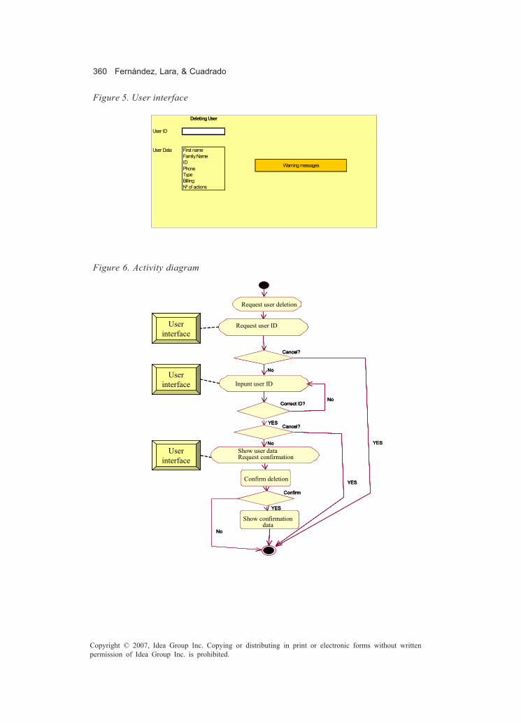
360 Fernández, Lara, & Cuadrado
Copyright © 2007, Idea Group Inc. Copying or distributing in print or electronic forms without writtenpermission of Idea Group Inc. is prohibited.
Figure 5. User interface
Cancel?
No
YES
Correct ID?No
Cancel?YES
Confirm
No
YES
YES
No
Request user deletion
Request user ID
Inpunt user ID
Show user dataRequest confirmation
Confirm deletion
Show confirmation data
User interface
User interface
User interface
Cancel?
No
YES
Correct ID?No
Cancel?YES
Confirm
No
YES
YES
No
Request user deletion
Request user ID
Inpunt user ID
Show user dataRequest confirmation
Confirm deletion
Show confirmation data
Cancel?
No
YES
Correct ID?No
Cancel?YES
Confirm
No
YES
YES
No
Request user deletion
Request user ID
Inpunt user ID
Show user dataRequest confirmation
Confirm deletion
Show confirmation data
User interface
User interface
User interface
Figure 6. Activity diagram
Deleting User
User ID
User Data First nameFamily NameIDPhoneTypeBillingNº of actions
Warning messages

Efficient Software Quality Assurance Approaches 361
Copyright © 2007, Idea Group Inc. Copying or distributing in print or electronic forms without writtenpermission of Idea Group Inc. is prohibited.
• Init deletion, ask for ID, introduce a correct ID, deletion is cancelled• Init deletion, ask for ID, introduce a correct ID, deletion is not confirmed
Secondly, following the traditional recommendations about black-box-test design, ananalysis of the domain of the input data values should be done to detect data groups orclasses with homogeneous behavior. This technique is called equivalence classes(Myers, 1979). An equivalence class may include a group of valid data and a group ofinvalid values. For instance, if an input specification describes a range of values, weconsider two classes of invalid data (values under and over the range limits) and a thirdone that groups all the valid values. Our second selection criterion can be described asfollows:
For each input data action in a use case, every valid equivalence classes should becovered using the minimum number of test cases but each invalid class should beinclude in a separated test case to monitor all the limit values.
In order to construct an activity diagram with complete information about equivalenceclasses, we propose to introduce a subdiagram for every activity node where data inputaction is involved. In the drop user example, if we assume that a valid user id is any integernumber with a maximum of six digits, the following data should be considered: 999999,000000, A546B6, 1000000, -000001.It is essential that this information appears in the activity diagram. UML hierarchicalactivity diagrams are implemented in all commercial tools (e.g., Rational Rose) so theycan be used to develop the diagram shown in Figure 7.Once these two criteria have been explained, the definition of our test-cases generationprocess is the following (Fernandez & Lara, 2003):
1. Generation of an activity diagram for each use case where the events flow pathsare indicated (see Figure 6).
2. Identification of data input action concerning each possible path in the diagram,analyzing the equivalence classes, boundary values, and possible combinedfunctioning ((Fernández, 2000) inspired on (Myers, 1979)).
3. Each input action should be considered an activity state containing a sub-diagramwhere each input option included (Figure 7), building the definitive diagram wheredecision nodes referred to correctness of input data disappear.
4. Execute both coverage criteria to cover each arrow or edge at least once.
One of the most important contributions of the process is the formalization of thealgorithm and all the elements involved in it (Escribano, Lara, Fernandez, & Hilera, 2005).In the following section, this formal model will be described and the algorithm itself willbe formalized.

362 Fernández, Lara, & Cuadrado
Copyright © 2007, Idea Group Inc. Copying or distributing in print or electronic forms without writtenpermission of Idea Group Inc. is prohibited.
ATABUS: Formal Models and Algorithms forTest Generation
The following elements will be used as basis for defining an AD:
• DA = Activity diagram• Ca = Path from the initial node to the final node.• NA = {graph nodes representing activities in the DA}• ND = {graph nodes representing decisions in the DA}• NF = {graph nodes representing forks in the DA}• NJ = {graph nodes representing joins in the DA}• T = Transitions in the DA, that is, every arrow between two different elements and
the associated guard, if it exits.• No = Origin of an arrow.• Nd = Destination of an arrow.
Now, an AD can be seen as:
G = (N, T)
Where N= NA U ND U NF U NJ U {start point, end point} and T= (edge, guard)andGuard ∈{λ, condition} being λ the empty setcondition = boolean expression
User ID 000000
User ID 999999
User ID1000000
User ID -000001
User ID no number
User ID 000000
User ID 999999
User ID1000000
User ID -000001
User ID no number
Figure 7. Introduction of the user ID subdiagram

Efficient Software Quality Assurance Approaches 363
Copyright © 2007, Idea Group Inc. Copying or distributing in print or electronic forms without writtenpermission of Idea Group Inc. is prohibited.
edge ,ji
N x N i jO d+
⊆ ∈ Ν
where·i j i j= ∨
and if
a. 1 1..k
i N N k i N NoJ Fd> ⇔ ∈ ∧∀ = ∉
b. 1 1..k
j N N k j N No F Jd> ⇔ ∈ ∧∀ = ∉
For the ATABUS algorithm, an extended formal model of AD is required. Beforeproceeding with this extended model, it is necessary to establish these three restrictions:
• A well-balanced and verified AD (Object Management Group, 2001) should be usedas starting point.
• We will use an acyclic AD because it is necessary to ensure that every node in theAD is visited at least once. Two types of loops can be found in an AD. Those wherethe probability of any number of cycles are the same and those where theprobability of a new cycle is decreasing. First type of loops can be simplified as anew alternate path with a fixed probability. The probability of the second oneshould follow a Poisson distribution.
• The probability of executing a transition is independent from the previous one.Fault proneness study is omitted to simplify the algorithm.
The elements we have to change are the following:
N’A = {graph nodes representing Activities in the DA plus the list of data to beconsidered}
In other words:
N’A = NA x data*
data = (id, value*)
where “*” represent the Kleen closure used in regular expressions.
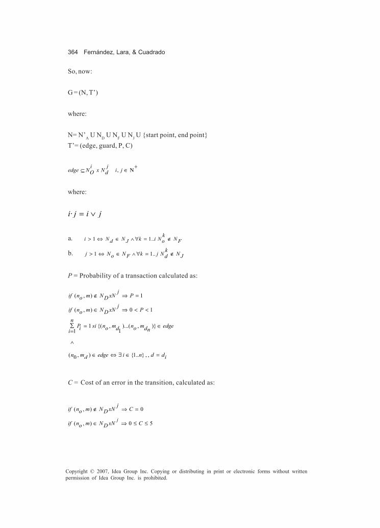
364 Fernández, Lara, & Cuadrado
Copyright © 2007, Idea Group Inc. Copying or distributing in print or electronic forms without writtenpermission of Idea Group Inc. is prohibited.
So, now:
G = (N, T’)
where:
N= N’A U ND U NF U NJ U {start point, end point}T’= (edge, guard, P, C)
,jiedge N x N i jO d
+⊆ ∈ Ν
where:
·i j i j= ∨
a. 1 1..k
i N N k i N NoJ Fd> ⇔ ∈ ∧ ∀ = ∉
b. 1 1..kj N N k j N No F Jd> ⇔ ∈ ∧ ∀ = ∉
P = Probability of a transaction calculated as:
( , ) 1
( , ) 0 1
1 {( , )...( , )}11
( , ) {1.. } , ,0
jif n m N xN Po D
jif n m N xN Po Dn
P si n m n m edgei o od dni
n m edge i n d did
∉ ⇒ =
∈ ⇒ < <
∑ = ∈=
∧
∈ ⇔ ∃ ∈ =
C = Cost of an error in the transition, calculated as:
( , ) 0
( , ) 0 5j
jif n m N xN Co D
if n m N xN Co D
∉ ⇒ =
∈ ⇒ ≤ ≤

Efficient Software Quality Assurance Approaches 365
Copyright © 2007, Idea Group Inc. Copying or distributing in print or electronic forms without writtenpermission of Idea Group Inc. is prohibited.
Based on this, it is possible to write two algorithms, one for generation and rank of pathsin the AD (test cases) and another for operation time evaluation.
The final algorithm ATABUS is stated as follows:
• Generate an AD, restrictions compliant, for each use case.
' ' AN N∀ ∈
where:
N’ = N x (d1,…dn )x OT
and:
n≠0
a. Assign values to attributes (P, C), using the techniques shown above.b. Build a subdiagram where each input data value is included (Figure 7) and
decision nodes referred to correctness of input data disappear. So:
)
( , ) *, :
(( , ), ( , , )i
id vi data create
a new node Ni
a new transition
t N Ni id v P C
∀ ∈
= =
)
(( , ), , , )
( )
( , *
t t t t t
i
i
and
t No Nd g P C T where
gt id v and
id v data
deleted t
∀ = ∈
= =
∈

366 Fernández, Lara, & Cuadrado
Copyright © 2007, Idea Group Inc. Copying or distributing in print or electronic forms without writtenpermission of Idea Group Inc. is prohibited.
• Let S the set of different paths existing in the new AD.
,
( , , , , ) :
( )
cos
( ) ( )
D
t t D t D
D
D
p
p
o d t t t
t
t
p S
let T the set of transitions in p
let T T such as
t N N g P C T No N
calculate the probability of p as
P p Pt T
and calculate the t of p as
C p CMaxt T
∀ ∈
⊆
= ∈ ⇔ ∈
=∈
=∈
∏
• Rank the paths (Test Cases) use the risk of every path as a function:
f (P(p), C(p)).
Integrated Tool Support for the Process
The ATABUS algorithm presented before is interesting for generating test cases formuse cases but it is not useful if there is not appropriate tool support for assuring efficiencyand comfortable process for developers. Following our philosophy, we have developeddiverse utilities for supporting the different tasks of the process, sometimes using COTSsoftware. Our choice for development was an open-source IDE with an extensible plug-in architecture to make easier to add new functionality. In that sense, Eclipse was chosenand a plug-in called AGAPE (in Spanish, Analysis & Automatic Generation of Test Caseswith Eclipse) was developed as the first prototype of the tool to cover the ATABUSalgorithm for test generation.Fully integrated with Eclipse, the AGAPE plug-in lets developers draw activity diagramsfor every use case defined on the system and fill out all the required information totransform the initial diagram into the extended one. AGAPE also generates automaticallythe test cases from the resulting diagram. Additionally, every test case will be associateda risk value that can be calculated from the information introduced by analyst aboutprobability of occurrence and cost of failure (Figure 8) for every possible bifurcation andfor every possible data value.

Efficient Software Quality Assurance Approaches 367
Copyright © 2007, Idea Group Inc. Copying or distributing in print or electronic forms without writtenpermission of Idea Group Inc. is prohibited.
This first prototype provides the following functionalities:
• A graphical editor to create an activity diagram• A graphical and textual editor to manage data activities, data, and values of this
data.• Generation of test cases from the information of the activity diagram. The test cases
are generated in XML language.
However, the whole process also needs further support for the rest of activities. SeveralEclipse plug-ins have been developed to help in quality assurance activities. Relatingwith OO metrics it is possible to find tools like TeamInABox that calculates variousmetrics for your code during build cycles and warns you, via the Task List, of ‘rangeviolations’ for each metric. Another plug-in like Metrics 1.3.5 offers up to 25 differentmetrics of UML models and source code. These utilities help reviewers to adapt theireffort to project conditions using Pareto analysis (as presented in “Review Processes”).Other plug-ins are more oriented to force programmers to write quality code, another keypoint for review processes. Jalopy, for example, is a source code formatter for the SunJava programming language. It formats any valid Java source code according to somewidely configurable rules to meet a certain coding style without putting a formattingburden on individual developers. CheckStyle is another java style checker but it does notchange code, it just warns that the lines of code do not comply with SUN style . Of course,this is not new since vendor tools not integrated with Eclipse — for example, Logiscope— also helps to follow style guides with the Rule Checker module (it also has a modulefor test coverage named TestChecker).
Figure 8. Snapshot of the AGAPE activity-diagram editor
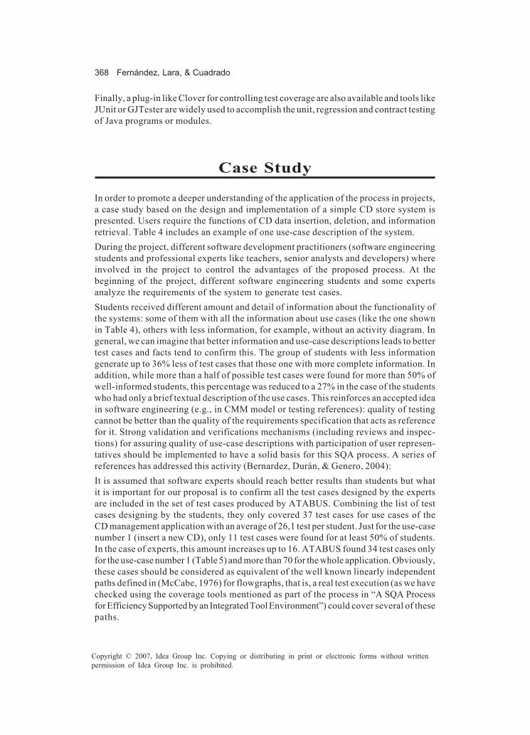
368 Fernández, Lara, & Cuadrado
Copyright © 2007, Idea Group Inc. Copying or distributing in print or electronic forms without writtenpermission of Idea Group Inc. is prohibited.
Finally, a plug-in like Clover for controlling test coverage are also available and tools likeJUnit or GJTester are widely used to accomplish the unit, regression and contract testingof Java programs or modules.
Case Study
In order to promote a deeper understanding of the application of the process in projects,a case study based on the design and implementation of a simple CD store system ispresented. Users require the functions of CD data insertion, deletion, and informationretrieval. Table 4 includes an example of one use-case description of the system.During the project, different software development practitioners (software engineeringstudents and professional experts like teachers, senior analysts and developers) whereinvolved in the project to control the advantages of the proposed process. At thebeginning of the project, different software engineering students and some expertsanalyze the requirements of the system to generate test cases.Students received different amount and detail of information about the functionality ofthe systems: some of them with all the information about use cases (like the one shownin Table 4), others with less information, for example, without an activity diagram. Ingeneral, we can imagine that better information and use-case descriptions leads to bettertest cases and facts tend to confirm this. The group of students with less informationgenerate up to 36% less of test cases that those one with more complete information. Inaddition, while more than a half of possible test cases were found for more than 50% ofwell-informed students, this percentage was reduced to a 27% in the case of the studentswho had only a brief textual description of the use cases. This reinforces an accepted ideain software engineering (e.g., in CMM model or testing references): quality of testingcannot be better than the quality of the requirements specification that acts as referencefor it. Strong validation and verifications mechanisms (including reviews and inspec-tions) for assuring quality of use-case descriptions with participation of user represen-tatives should be implemented to have a solid basis for this SQA process. A series ofreferences has addressed this activity (Bernardez, Durán, & Genero, 2004):It is assumed that software experts should reach better results than students but whatit is important for our proposal is to confirm all the test cases designed by the expertsare included in the set of test cases produced by ATABUS. Combining the list of testcases designing by the students, they only covered 37 test cases for use cases of theCD management application with an average of 26,1 test per student. Just for the use-casenumber 1 (insert a new CD), only 11 test cases were found for at least 50% of students.In the case of experts, this amount increases up to 16. ATABUS found 34 test cases onlyfor the use-case number 1 (Table 5) and more than 70 for the whole application. Obviously,these cases should be considered as equivalent of the well known linearly independentpaths defined in (McCabe, 1976) for flowgraphs, that is, a real test execution (as we havechecked using the coverage tools mentioned as part of the process in “A SQA Processfor Efficiency Supported by an Integrated Tool Environment”) could cover several of thesepaths.
Efficient Software Quality Assurance Approaches 369
Copyright © 2007, Idea Group Inc. Copying or distributing in print or electronic forms without writtenpermission of Idea Group Inc. is prohibited.
Table 4. Use-case description example
Showerror
ShowInsert Dialog
User fi llsdata fields
Accept?
Does CDexist?
Add to the list

370 Fernández, Lara, & Cuadrado
Copyright © 2007, Idea Group Inc. Copying or distributing in print or electronic forms without writtenpermission of Idea Group Inc. is prohibited.
Table 5. Test cases for Insert CD use case
Test ID Short Description Path Valid?
1 User cancels MP-RD(Mclan, Sin Enchufe, 13,90, 1:05:20)-Fin Si
2 Insert existent CD + cancel MP-RD(Mclan, Sin Enchufe, 13,90, 1:05:20)-ME-MP-Fin Si
3 Insert existent CD + Insert non-existent CD
MP-RD(Mclan, Sin Enchufe, 13,90, 1:05:20)-ME-MP-RD(Mclan, Sopa Fría, 13,90, 1:05:20)-AL-Fin Si
4 Insert non-existent CD MP-RD(m, Sin Enchufe, 13,90, 1:05:20)-AL-Fin Si
5 Insert non-existent CD MP-RD(012345678901234567890123456789, Sin Enchufe, 13,90, 1:05:20)-AL-Fin Si
6 Insert non-existent CD MP-RD(Mclan, s, 13,90, 1:05:20)-AL-Fin Si
7 Insert non-existent CD MP-RD(Mclan, 012345678901234567890123456789, 13,90, 1:05:20)-AL-Fin Si
8 Insert non-existent CD MP-RD(Mclan, Sin Enchufe, 13, 1:05:20)-AL-Fin Si 9 Insert non-existent CD MP-RD(Mclan, Sin Enchufe, 0, 1:05:20)-AL-Fin Si
10 Insert non-existent CD MP-RD(Mclan, Sin Enchufe, 13,90, 0:55:20)-AL-Fin Si 11 Insert non-existent CD MP-RD(Mclan, Sin Enchufe, 13,90, 1:0:20)-AL-Fin Si 12 Insert non-existent CD MP-RD(Mclan, Sin Enchufe, 13,90, 1:05:0)-AL-Fin Si 13 Insert non-existent CD MP-RD(Mclan, Sin Enchufe, 13,90, 25:05:0)-AL-Fin Si 14 Insert non-existent CD MP-RD(, Sin Enchufe, 13,90, 1:05:20)-ME No
15 Insert CD – Wrong Data
MP-RD(MasDe30/012345678901234567890123456789, Sin Enchufe, 13,90, 1:05:20)-ME No
16 Insert CD – Wrong Data MP-RD(Mclan, , 13,90, 1:05:20)-ME No
17 Insert CD – Wrong Data
MP-RD(Mclan, MasDe30/012345678901234567890123456789, 13,90, 1:05:20)-ME No
18 Insert CD – Wrong Data MP-RD(Mclan, Sin Enchufe, , 1:05:20)-ME No
19 Insert CD – Wrong Data MP-RD(Mclan, Sin Enchufe, aa,90, 1:05:20)-ME No
20 Insert CD – Wrong Data MP-RD(Mclan, Sin Enchufe, 13.90, 1:05:20)-ME No
21 Insert CD – Wrong Data MP-RD(Mclan, Sin Enchufe, -13,90, 1:05:20)-ME No
22 Insert CD – Wrong Data MP-RD(Mclan, Sin Enchufe, 2^64, 1:05:20)-ME No
23 Insert CD – Wrong Data MP-RD(Mclan, Sin Enchufe, 13,90, )-ME No
24 Insert CD – Wrong Data MP-RD(Mclan, Sin Enchufe, 13,90, 1:05)-ME No
25 Insert CD – Wrong Data MP-RD(Mclan, Sin Enchufe, 13,90, 1:05:20:50)-ME No
26 Insert CD – Wrong Data MP-RD(Mclan, Sin Enchufe, 13,90, aa:05:20)-ME No
27 Insert CD – Wrong Data MP-RD(Mclan, Sin Enchufe, 13,90, 1:aa:20)-ME No
28 Insert CD – Wrong Data MP-RD(Mclan, Sin Enchufe, 13,90, 1:05:aa)-ME No
29 Insert CD – Wrong Data MP-RD(Mclan, Sin Enchufe, 13,90, 25:05:20)-ME No
30 Insert CD – Wrong Data MP-RD(Mclan, Sin Enchufe, 13,90, -1:05:20)-ME No
31 Insert CD – Wrong Data MP-RD(Mclan, Sin Enchufe, 13,90, 1:100:20)-ME No
32 Insert CD – Wrong Data MP-RD(Mclan, Sin Enchufe, 13,90, 1:-05:20)-ME No
33 Insert CD – Wrong Data MP-RD(Mclan, Sin Enchufe, 13,90, 1:05:100)-ME No
34 Insert CD – Wrong Data MP-RD(Mclan, Sin Enchufe, 13,90, 1:05:-20)-ME No
Efficient Software Quality Assurance Approaches 371
Copyright © 2007, Idea Group Inc. Copying or distributing in print or electronic forms without writtenpermission of Idea Group Inc. is prohibited.
The comprehensive number of test cases initially generated by ATABUS is the seed thatmake necessary to rank them to get the maximum number of defects with the minimumnumber of executions of test. Unfortunately, the quality of results of testing usingATABUS depends on the quality of risk analysis: probability, severity, and faultproneness and, at least, the first two issues are expert dependent, so a big effort inimprove skills and knowledge of project managers and analysts about metrics, risks, andso on, is essential.After the initial generation of tests cases, a series of inspections and evaluations aboutimportant software metrics were performed to follow the process. Style and certain typesof design defects were detected using Checkstyle and other metric tools like thosementioned in “Integrated Tool Support for the Process”. Thus, preventive detection andfewer defects (not easily detectable with testing) were fixed before reaching the testexecution phase. As an example of dangerous defects detected, the following pieces ofcode are presented.
for (Iterator i = getCDsIterator(); i.hasNext())CD cd = (CD) i.next();if (cd.getArtista().equals(artista)) {
resultado += cd + “\n”;}
for (Iterator i = getCDsIterator(); i.hasNext()) {CD cd = (CD) i.next();if (cd.getArtista().equals(artista)) {
resultado += cd + “\n”;}
}
The code on the top column does not accomplish the style rules of Sun for Java code:a “for” block should be always between braces. A developer could believe that the “if”block are inside the “for” block, but it is really outside the loop, making the codeerroneous. The use of braces on the right column avoids this kind of errors. Table 6 andFigure 9 are example of metrics and audit reports provided by the tools integrated withEclipse for this project.

372 Fernández, Lara, & Cuadrado
Copyright © 2007, Idea Group Inc. Copying or distributing in print or electronic forms without writtenpermission of Idea Group Inc. is prohibited.
Figure 9. Warnings about code style generated by Checkstyle plug-in for Eclipse
Future Trends
ATABUS provides a process to automate the generation of test cases from UMLspecification. A first tool to implement part of the process has been developed. However,as we have shown, what it is efficient is a framework to specify requirements, generatetests, and execute them and this is clearly much more than a set of isolated tools withdifferent functionality and a common purpose. Vendors and researchers are now
Table 6. Metrics report automatically generated by TeamInABox Eclipse plug-ins

Efficient Software Quality Assurance Approaches 373
Copyright © 2007, Idea Group Inc. Copying or distributing in print or electronic forms without writtenpermission of Idea Group Inc. is prohibited.
focusing their proposals not only in different methods and techniques but also especiallyin integration of tool support to avoid extra efforts to developers.In fact, in the future we expect that construction of real integrated environments (bycommercial proprietary vendors or in open environments like Eclipse) will allow, at least,the following features:
• Use-case extended specification: Activity diagrams include with all the necessaryinformation to enable risk analysis.
• Integration of more sophisticated metrics tools to evaluate models and design:Even more, it is probable that tools will be able to give advice for using designpatterns (Grand, 1999).
• Traceability cube form: This cube should allow the refinement of the risk analysiswith information about fault-proneness ratios obtained from metrics tools and theguided replication of test when specification changes.
• Redefinition of a test specification language: To get executable scripts from it thatmake easier to execute the test cases generated using the algorithm.
• Integration of GUI, unit, and regression testing tools: To cover all these kind oftests with the same language and supporting with all the information collectedduring the process.
• Coverage analysis of the final set of most important tests: To ensure a goodcoverage percentage.
Conclusion
It is frequent to hear software managers to say that quality and productivity are notcompatible. Sometimes this feeling is stimulated by the low perception of efficiency andcapability of customization of SQA techniques. As we have presented in the introduc-tion, there are several work lines to support the need of productivity, especially theinclusion of serious risk analysis and the transfer of task from humans to tools. We hopethat the different methods, techniques and tools presented along the process for aminimum SQA activity could be enough to stimulate a more positive attitude to theinclusion of these techniques that has been proven very useful for developers andmanagers, with interesting ROI figures. Obviously, one important lesson for practitio-ners is the absence of silver bullets: each organisation should customize the use of toolsand techniques to each project, depending on the risk level they can afford, availableresources, and so on. Obviously, managers and developers should be well educated indisciplines like metrics and SQA to exploit the advantages of this process.
374 Fernández, Lara, & Cuadrado
Copyright © 2007, Idea Group Inc. Copying or distributing in print or electronic forms without writtenpermission of Idea Group Inc. is prohibited.
References
Abreu, F., & Melo, W. (1996). Evaluating the impact of object oriented design onsoftware quality. Paper presented at the 3rd International Symposium on SoftwareMetrics: From Measurement to Empirical Results, Berlin, Germany.
Ahlowalia, N. (2002). Testing from use cases using path analysis technique. Paperpresented at Object System Group. International Conference On Software TestingAnalysis & Review, Edimburg, Scotland.
Basili, V., Briand, L., & Melo, W. L. (1996) A validation of object-oriented design metricsas quality indicators. IEEE Transactions on Software Engineering, 22(10), 751-760.
Beizer, B. (1990). Softwaretesting techniques. New York: VanNostrand Reinhold.Beizer, B. (1995). Black-box testing. New York: John Wiley & Sons.Bernárdez, B., Durán, A., & Genero, M. (2004). Empirical evaluation and review of a
metrics-based approach for use case verification. Journal of Research and Prac-tice in Information Technology, 36(4), 247-257.
Biffl, S., & Halling, M. (2002). Investigating the influence of inspector capability factorswith four inspection techniques on inspection performance. Paper presented atthe Eighth IEEE Symposium on Software Metrics (METRICS’02), Ottawa, Canada.
Biffl, S., & Halling, M. (2003). Investigating the defect detection effectiveness and costbenefit of nominal inspection teams. IEEE Transactions On Software Engineer-ing, 29(5), 385-397.
Booch, G., Rumbaugh, J., & Jacobson, I. (1998). The Unified Modeling Language userguide. MA: Addison-Wesley.
Boodoo, S., El-Emam, K., Laitenberger, O., & Madhavji, N. (2000), The optimal team sizefor UML design inspections (NRC/ERB-1081). Ottawa: National Research Councilof Canada, Institute for Information Technology.
Borrajo, J. (1994). Automated metrics to measure the UK.Borrajo, J. (1995). A tool and a set of metrics to support technical reviews. Paper
presented at Software Quality Management IV, Seville, Spain.Briand, L., Wuest, J., & Iconomovski, S. (1998). A comprehensive investigation of quality
factors in object-oriented designs: An industrial case study (Tech. Rep. No.ISERN-98-29). Los Angeles, CA: International Software Engineering ResearchNetwork.
Chrissis, M. B., Konrad, M., & Shrum, S. (2003). CMMI®: Guidelines for processintegration and product improvement. Menlo Park: Addison-Wesley.
Crowther, D. C., & Clarke, P. J. (2005). Examining software testing tools. Dr. DobbsJournal,18(373), 26-33.
Escribano, J. J., Lara, P. J., Fernandez, L., & Hilera, J. R. (2005). A study of the relationshipbetween usability and test cases precedence based on a formal model for activity

Efficient Software Quality Assurance Approaches 375
Copyright © 2007, Idea Group Inc. Copying or distributing in print or electronic forms without writtenpermission of Idea Group Inc. is prohibited.
diagrams. Paper presented at the International Conference on Software Engineer-ing Research and Practice (SERP’05), Las Vegas, NV.
Fagan, M. E. (1986). Advances in software inspections. IEEE Transactions on SoftwareEngineering, 12(7), 744-751.
Fernández, J. L. (2000). Utilización de casos de uso en las pruebas de aceptación.. InProceedings of the V Jornadas de Innovación y Calidad del Software, SanSebastián, Spain (pp. 65-76).
Fernández, L., & García, M. J. (2003). Software engineering professionalism. Upgrade,4(4), 42-46.
Fernandez, L., & Lara, P. J. (2003). Generación de casos de prueba a partir deespecificaciones UML. In Proceedings of the VIII Jornadas de Innovación yCalidad del Software, Barcelona, Spain (pp. 48-58).
Fernandez, L., Lara, P. J., Escribano, J. J., & Villalba, M. T. (2004). Use cases for enhancingIS requirements management. Paper presented at the IADIS International Confer-ence: e-Society, Ávila, Spain.
Friedman, G., Hartman, A., & Shiran, K. N. a. T. (2002). Projected state machine coveragefor software testing. In Proceedings of the 2002 ACM SIGSOFT InternationalSymposium on Software Testing and Analysis (pp. 134-143). Rome, Italy: ACMPress.
Grady, R., & Caswell, D. (1987). Software metrics: Establishing a company-wideprogram. Englewood Cliffs, NJ: Prentice-Hall.
Grand, M. (1999). Patterns in Java:Aa catalog of reusable design patterns illustratedwith UML. New York: John Wiley & Sons.
Harel, D. (1988). On visual formalisms. Communication of the ACM,31(5), 514-530.Hassan, A., Abdelmoez, W., Elnaggar, R., & Ammar, H. (2001). An approach to measure
the quality of software designs from UML specifications. Paper presented at theFifth World Multi-Conf. Systems, Cybernetics and Informatics, Orlando, FL.
Heumann, J. (2001, June). Generating test cases from use cases. The Rational Edge.Humphrey, W. S. (1996). Introduction to the personal software process. Boston:
Addison-Wesley.Hutcheson, M. L. (2003). Software testing fundamentals. Indianapolis, IN: Wiley Pub-
lishing, Inc.IEEE Computer Society. (1991). IEEE 610-1991 computer dictionary. New York: author.IEEE Computer Society. (1997). IEEE 1074-1997 IEEE standard for developing software
life cycle processes. New York: author.IEEE Computer Society. (1998). IEEE 730-1998 standard for software quality assurance
plans. New York: author.ISO. (2000a). Quality management systems — Fundamentals and vocabulary. Geneve,
Italy.ISO. (2000b). Quality management systems — Requirements. Geneve, Italy.

376 Fernández, Lara, & Cuadrado
Copyright © 2007, Idea Group Inc. Copying or distributing in print or electronic forms without writtenpermission of Idea Group Inc. is prohibited.
ISO. (2004). Information technology. Process assessment. Part 1: Concepts and vocabu-lary. Geneve, Italy.
Jacobson, I., Booch, G., & Rumbaugh, J. (1999). The unified software developmentprocess. Boston: Addison-Wesley
Jones, C. (1994). Assessment and control of software risks. Saddle River: Yourdon Press.Kan, S. H. (2002). Metrics and models in software quality engineering. Reading, MA:
Addison WesleyKangasluoma, M. (2000). Test case generation from UML state chart. Master thesis.
Finland: Helsinky University of Technology.Kosmatov, N., Legeard, B., Peureux, F., & Utting, M. (2004). Boundary coverage criteria
for test generation from formal models. In Proceedings of the 15th InternationalSymposium on Software Reliability Engineering (ISSRE 2004), Saint-Malo,France (pp. 139-150).
Lara, P .J., & Fernández, L. (2004, April). ¿Cómo mejorar el estilo en desarrollos Java? DrDobbs Journal España, 54-59.
McCabe, T. (1976). A software complexity measure. IEEE Transactions on SoftwareEngineering, 2(6), 308-320
McConnell, S. (1996). Rapid development: Taming wild software schedules. Redmond,WA: Microsoft Press.
Memon, A. M., Soffa, M. L., & Pollack, M. E. (2001). Coverage criteria for GUI testing.Paper presented at the 8th European Software Engineering Conference HeldJointly with 9th ACM SIGSOFT International Symposium on Foundations ofSoftware Engineering, Vienna, Austria (pp. 256-267).
Munson, J., & Khoshgoftaar, T. (1996). Software metrics for reliability assessment. In M.R. Lyu (Ed.), Handbook of software reliability and system reliability. Hightstown:McGraw-Hill.
Myers, G. J. (1979). The art of software testing. New York: John Wiley & Sons.NASA (1997). NASA technical standard 8719.13A, software safety. Washington, DC.Ntafos, S. (1988). A comparison of some structural testing strategies. IEEE Transactions
on Software Engineering, 14(6), 868-874.Object Management Group (OMG). (2001). Unified Modeling Language (Technical
report of Object Management Group). Needham, MA.Offutt, J., & Abdurazik, A. (1999). Generating tests from UML specifications. Paper
presented at UML’99 — The Unified Modeling Language. Beyond the Standard.Second International Conference, Fort Collins, TX.
Ohlsson, M., & Wholin, C. (1998). Identification of green, yellow, and red legacycomponents. In Proceedings of the International Conference on Software Main-tenance, ICSM’98, Bethesda, MD (pp. 6-15).
Ohlsson, M., Von Mayrhauser, A., McGuire, B., & Wohlin, C. (1999). Code decayanalysis of legacy software through successive releases. Paper presented at IEEEAerospace Conference, Aspen, CO.
Efficient Software Quality Assurance Approaches 377
Copyright © 2007, Idea Group Inc. Copying or distributing in print or electronic forms without writtenpermission of Idea Group Inc. is prohibited.
Pressman, R. S. (2003), Software engineering: A practitioners’ approach. Boston:McGraw-Hill.
Roper, M. (1994). Software testing. London: McGraw-HillRumbaugh, J., Jacobson, I., & Booch, G. (1998). The Unified Modeling Language
reference manual. Reading, MA: Addison-WesleyRyser, J. M., & Glintz, M. (2002/03). SCENT: A method employing scenarios to system-
atically derive test cases for system test. Zurich, Switzerland: Institut für Informatik.Schneider, G., & Winters, J. P. (2001). Applying use cases: A practical guide. Reading,
MA: Adisson-Wesley.Schulmeyer, G. G. (1992). Handbook of software quallity assurance. Reinhold: Van Nost.Stringfellow, C., & Andrews, A. (2002). Deriving a fault architecture to guide testing.
Software Quality Journal, 10(4), 299-330. Vincenzi, A., Maldonado, J., & Delamaro, W. W. a. M. (2005). Coverage testing of Java
programs and components. Science of Computer Programming, 56(1-2), 211-230. Von Mayrhauser, A., Wang, J., Ohlsson, M., & Wohlin, C. (1999). Deriving a fault
architecture from defect history. Paper presented at International Conference onSoftware Reliability Engineering, Boca Ratón, Florida.
Walton, G., Poore, J., & Trammell, C. (1995). Statistical testing of software based on ausage model. Software, Practice and Experience, 25(1), 97-108.
Wheeler, D. A., Brykczynski, B., & Meeson, R. A. (Eds.). (1996). Software inspection:An industry best practice. Los Alamitos, CA: IEEE Computer Society Press.
Wohlin, C., & Runeson, P. (1995). Experimental evaluation of capture-recapture insoftware inspections. Journal of Software Testing, Verification and Reliabil-ity, 5(4), 213-232.
Woodward, M., Hedley, D., & Hennell, M. (1980). Experience with path analysis andtesting of programs. IEEE Transactions on Software Engineering, 6(3), 278-286.

378 Hsiung, Lin, & Chen
Copyright © 2007, Idea Group Inc. Copying or distributing in print or electronic forms without writtenpermission of Idea Group Inc. is prohibited.
Chapter XIV
Safecharts ModelChecking for theVerification of
Safety-Critical SystemsPao-Ann Hsiung, National Chung Cheng University, Taiwan
Yen-Hung Lin, National Chung Cheng University, Taiwan
Yean-Ru Chen, National Chung Cheng University, Taiwan
Abstract
Unintentional design faults in safety-critical systems might result in injury or evendeath to human beings. However, the safety verification of such systems is getting verydifficult because designs are becoming very complex. To cope with high designcomplexity, model-driven architecture (MDA) design is becoming a well-acceptedtrend. However, conventional methods of code testing and hazard analysis do not fitvery well with MDA. To bridge this gap, we propose a safecharts model-based formalverification technique for safety-critical systems. The safety constraints in safechartsare mapped to semantic equivalents in timed automata. The theory for safety verificationis proved and implemented in the SGM model checker. Prioritized and urgent transitionsare implemented in SGM to model the safechart risk semantics. Finally, it is shown that
Safecharts Model Checking 379
Copyright © 2007, Idea Group Inc. Copying or distributing in print or electronic forms without writtenpermission of Idea Group Inc. is prohibited.
priority-based approach to mutual exclusion of resource usage in safecharts is unsafeand solutions are proposed. Application examples show the benefits of the proposedmodel-driven verification method.
Introduction
Safety-critical systems are systems whose failure most probably results in the tragic lossof human life or damage to human property. There are numerous examples of thesemishaps. The accident at the Three Mile Island (TMI) nuclear power plant in Pennsyl-vania on March 28, 1979 is just one unfortunate example (Leveson, 1995). Moreover, astime goes on, there are more and more cars, airplanes, rapid transit systems, medicalfacilities, and consumer electronics, which are all safety-critical systems in our dailylives. When some of them malfunction or fault, a tragedy is inevitable. The naturalquestion here is: Should we use these systems without a very high confidence in theirsafety? Obviously, the answer is no. That is why we need some methodology toexhaustively verify safety-critical systems.Traditional verification methods such as simulation and testing can only prove thepresence of faults and not their absence. Some methods such as fault-based testing andsemiformal verification that integrates model checking and testing can prove the absenceof prespecified faults. Simulation and testing (Sommerville, 2004) are both required beforea system is deployed to the field. While simulation is performed on an abstract model ofa system, testing is performed on the actual product. In the case of hardware circuits,simulation is performed on the design of the circuit, whereas testing is performed on thefabricated circuit itself. In both cases, these methods typically inject signals at certainpoints in the system and observe the resulting signals at other points. For software,simulation and testing usually involve providing certain inputs and observing thecorresponding outputs. These methods can be a cost-efficient way to find many errors.However, checking all of the possible interactions and potential pitfalls using simulationand testing techniques is rarely possible. Conventionally, safety-critical systems arevalidated through standards conformance and code testing. Using such verificationmethods for safety-critical systems cannot provide the desired 100% confidence onsystem correctness.In contrast to the traditional verification methods, formal verification is exhaustive.Further, unlike simulation, formal verification does not require any test benches or stimulifor triggering a system. More precisely, formal verification is a mathematical way ofproving a system satisfies a set of properties. Formal verification methods such modelchecking (Clarke & Emerson, 1981; Clarke, Grumberg, & Peled, 1999; Queille & Sifakis,1982) are being taken seriously in the recent few years by several large hardware andsoftware design companies such as Intel, IBM, Motorola, and Microsoft, which goes toshow the importance and practicality of such methods for real-time embedded systemsand SoC designs. For the above reasons, we will thus employ a widely popular formalverification method called model checking for the verification of safety-critical systemsthat are formally modeled.

380 Hsiung, Lin, & Chen
Copyright © 2007, Idea Group Inc. Copying or distributing in print or electronic forms without writtenpermission of Idea Group Inc. is prohibited.
Model checking (Clarke & Emerson, 1981; Clarke et al., 1999; Queille & Sifakis, 1982) isa technique for verifying finite state concurrent systems. One benefit of this restrictionis that verification can be performed automatically. The procedure normally uses anexhaustive search of the state space of a system to determine if some specification is trueor not. Given sufficient resources, the procedure will always terminate with a yes/noanswer. Moreover, algorithms can implement it with reasonable efficiency, which can berun on moderate-sized machines. The process of model checking includes three parts:modeling, specification, and verification. Modeling is to convert a design into aformalism accepted by a model-checking tool. Before verification, specification, whichis usually given in some logical formalism, is necessary to state the properties that thedesign must satisfy. The verification is completely automated. However, in practice itoften involves human assistance. One such manual activity is the analysis of theverification results. In case of a negative result, the user is often provided with an errortrace. This can be used as a counterexample for the checked property and can help thedesigner in tracking down where the error occurred. In this case, analyzing the error tracemay require a modification to the system and a reapplication of the model-checkingalgorithm.A safety-critical system model and its model checking procedures are implemented in thestate-graph manipulators (SGM) model checker (Wang & Hsiung, 2002), which is a high-level model checker for both real-time systems as well as systems-on-chip modeled bya set of timed automata.The remaining portion is organized as follows. The current state-of-art in the verificationof safety-critical systems, especially how formal verification has been integrated intoconventional techniques, is described in the section on Related Work. Basic definitionsused in our work are given in the section on System Model, Specification, and ModelChecking, along with an illustrative railway signaling system example. The section onModel Checking Safecharts will formulate each of our solutions to solving the issuesencountered in formally verifying safety-critical systems modeled by safecharts. Imple-mentation details of the proposed method in the SGM model checker are given in thesection on the Implementation in a Model Checker. Application examples are given infollowing section. The article is concluded and future research directions are given inthefinal section.
Related Work
Traditionally, safety-critical systems have been verified mainly using hazard-analysistechniques such as checklists; hazard indices; fault-tree analysis (FTA); managementoversight and risk-tree analysis (MORT); event-tree analysis; cause-consequenceanalysis (CCA); hazards-and-operability analysis (HAZOP); interface analysis; failuremodes and effects analysis (FMEA); failure modes, effects, and criticality analysis(FMECA); and fault-hazard analysis (FHA) (Leveson, 1995). Hazard analysis is acontinual and iterative process, which generally includes the following steps: definitionsof objectives and scope, system description, hazard identification, data collection,
Safecharts Model Checking 381
Copyright © 2007, Idea Group Inc. Copying or distributing in print or electronic forms without writtenpermission of Idea Group Inc. is prohibited.
qualitative ranking of hazards, identification of causal factors, identification and evalu-ation of corrective measures, verification of control implementations, quantification ofunresolved hazards and residual risks, and feedback and evaluation of operationalexperience. Hazard-analysis techniques have been successfully applied to severaldifferent real-world safety-critical systems. Nevertheless, a major limitation of hazardanalysis is that phenomena unknown to the analysts are not covered in the analysis, andthus hazards related to the phenomena are not foreseen. This becomes a severe limitationwhen the system is complex and analysts may overlook some possible hazards. Safety-critical systems are getting increasingly complex, and there is a trend to use methods(Bozzano, 2003; Jacky, 2000) that are more automatic and exhaustive than hazard analysis— for example, model checking.The verification of safety-critical systems using formal techniques is not something new(Leveson, 1995). This can be seen in methods such as state-machine hazard analysis thatwas based on Petri nets (Leveson & Stolzy, 1987) and the application of model checkingto safety-critical system verification based on various formal models such as finite statemachines (Bozanno, 2003), statecharts (Bozzano, 2003), process control event diagrams(Yang, Chung, Kowalewski, & Stursberg, 2000), Scade (Deneux & Akerlund, 2004), andAltarica (Bozzano, 2003). A common method for the application of model checking tosafety-critical system verification is through the specification of safety-related proper-ties using some temporal logic such as CTL or LTL and then checking for the satisfactionof the safety specification (Johnson, 2002). However, as noted by Leveson (1995), thisapproach is inadequate because in the system models we are assuming that all thecomponents do not fail and the system is proved to be safe under this assumption.However, the assumption is not valid so transforming each hazard into a formal propertyfor verification as in (Johnson) is not sufficient. Some work have also integratedtraditional FTA techniques with model checking such as in the Enhanced SafetyAssessment for Complex Systems (ESACS) project (Bozzano, 2003; European Union,2003), which expressed the minimal cut sets (MCS), that is, the minimal combinations ofcomponent failures, generated by a model checker, using fault trees. Nevertheless, asafety engineer must still inject failure modes of components into the system modelbefore model checking can be performed. Bieber, Castel, and Seguin (2002) used modelchecking as a means to check if all unexpected events have been eliminated byconventional FTA techniques. Yang et al. defined various fault modes for each compo-nent and used model checking in each fault mode to check for safety properties. In allthe above models and methods, safety-related actions such as failure mode capturing,safety requirements capturing, and model analysis must all be performed separately fromthe model checking process. In this chapter, the work on using safecharts to verifysafety-critical systems contributes to the state-of-art in formal verification of suchsystems in several ways as described in the following:
1. The unified modeling language (UML) is an industry de-facto standard for model-driven architecture design. Safecharts, being an extension of the UML statecharts,blends naturally with the semantics of other UML diagrams for the design of safety-critical systems. The work described in this article automatically transformssafecharts into the timed automata model that can be accepted by conventional
382 Hsiung, Lin, & Chen
Copyright © 2007, Idea Group Inc. Copying or distributing in print or electronic forms without writtenpermission of Idea Group Inc. is prohibited.
model checkers. Thus, safecharts is suitable for both design and verification, thusacting as a bridge between the two, the link between which was seen as an “overthe wall process” for a long time (Fenelon, McDermid, Nicholson, & Pumfrey, 1994).
2. Safecharts allow and require the explicit modeling of component failures andrepairs within the safety layer of its models. This is unique and is very helpful notonly for the safety design engineer but also for the safety verification engineer.Further, using safecharts, there is no need to separately define failure modes andeffects, thus preventing accidental omissions and inconsistent specifications.
3. The work here shows how a conventional model checker can be extended toperform safety-critical system verification, without the need to integrate conven-tional methods. Safecharts play a major role in the feasibility of such a simpleextension through its unique features of risk states, transition priorities, andcomponent failure and repair modeling artifacts.
4. Due to safecharts being a variant of the UML statecharts, automatic code genera-tion is supported through model-driven development that is becoming a standardway of software code design. Safety requirements proved in the models can thusbe preserved into the final software code through this automatic code generationprocess. This is out of scope here in this work, but is an added advantage that mustbe carefully proved.
System Model, Specification,and Model Checking
Before going into the details of how safecharts are used to model and verify safety-criticalsystems, some basic definitions and formalizations are required as given in this Section.Both safecharts and their translated ETA models will be defined. TCTL and modelchecking will also be formally described. A railway signaling system is used as a runningexample for illustration. Since safecharts is based on the UML statecharts, we first definestatecharts in Definition 1 and then define safecharts in Definition 2.
• Definition 1: Statecharts. Statecharts are a tuple F = (S, T, E, θ, V, φ), where S isa set of all states, Τ is a set of all possible transitions, E is a set of all events, θ isthe set of possible types of states in statecharts, that is, θ = {AND, OR, BASIC},V is a set of integer variables, and φ ::= v ~ c | φ1 ∧ φ2 | ¬φ1, in which v ∈ V, ~ ∈ {<,≤, =, ≥, >}, c is an integer, and φ1 and φ2 are predicates. Let Fi be an arbitrary statein S. It has the general form:
Fi = (θi, Ci, di, Ti, Ei, li ) where:
� θi : the type of the state Fi; θi ∈ θ
Safecharts Model Checking 383
Copyright © 2007, Idea Group Inc. Copying or distributing in print or electronic forms without writtenpermission of Idea Group Inc. is prohibited.
� Ci : a finite set of direct substates of Fi, referred to as child states of Fi, Ci ⊆S.
� di : di ∈ Ci and is referred to as the default state of Fi. It applies only to OR states.� Ti : a finite subset of F × F, referred to as explicitly specified transitions in Fi.� Ei : the finite set of events relevant to the specified transitions in Ti; Ei ⊆ E.� li : a function Ti → E × φ × 2Ei, labeling each and every specified transition in
Ti with a triple, 2Ei denoting the set of all finite subsets of Ei.
Given a transition t ∈ T, its label is denoted by l(t) = ( e, fcond, a ), written conventionallyas e[fcond]/a. e, fcond and a in the latter, denoted also as trg(t) = e, con(t) = fcond, andgen(t) = a, represent respectively the triggering event, the guarding condition and theset of generated actions.Safecharts (Dammag & Nissanke, 1999; Nissanke & Dammag, 2000, 2002; Lin & Hsiung,2005) is a variant of statecharts intended exclusively for safety-critical systems design.With two separate representations for functional and safety requirements, safechartsbrings the distinctions and dependencies between them into sharper focus, helping bothdesigners and auditors alike in modeling and reviewing safety features. Figure 1 showsthe functional and safety layers of a safecharts model for setting a route of a railwaysystem. The functional layer specifies the normal functions of requesting and setting orrejecting a route. The safety layer enforces the safety restrictions for setting or unsettinga route. The notations ! and ! in the safety layer will be defined in Definition 2 and basicallyrestricts setting a route or enforces the release of a route when any of the signals in thatroute is or becomes faulty.Further, safecharts incorporates ways to represent equipment failures and failurehandling mechanisms and uses a safety-oriented classification of transitions and asafety-oriented scheme for resolving any unpredictable nondeterministic pattern ofbehavior. It achieves these through an explicit representation of risks posed by hazard-ous states by means of an ordering of states and a concept called risk band (Lin & Hsiung,2005). Recognizing the possibility of gaps and inaccuracies in safety analysis, safechartsdo not permit transitions between states with unknown relative risk levels. However, inorder to limit the number of transitions excluded in this manner, safecharts provides adefault interpretation for relative risk levels between states not covered by the riskordering relation, requiring the designer to clarify the risk levels in the event of adisagreement and thus improving the risk assessment process.
• Definition 2: Safecharts. Safecharts Z extends statecharts by adding a safety-layer. States are extended with a risk ordering relation and transitions are extendedwith safety conditions. Given two comparable states s1 and s2, a risk orderingrelation � specifies their relative risk levels, that is s1 � s2 specifies s1 is safer thens2. Transition labels in safecharts have an extended form: e[fcond]/a[l, u) ψ[G]where e, fcond, and a are the same as in statecharts. The time interval [l, u) is a real-time constraint on a transition t and imposes the condition that t does not executeuntil at least l time units have elapsed since it most recently became enabled and

384 Hsiung, Lin, & Chen
Copyright © 2007, Idea Group Inc. Copying or distributing in print or electronic forms without writtenpermission of Idea Group Inc. is prohibited.
Figure 1. Safechart for route[x] with functional and safety layers
Figure 2. Routes and signals
signal[i]
signal[j]
signal[k]
route[x] route[y]
must execute strictly within u time units. The expression ψ[G] is a safety enforce-ment on the transition execution and is determined by the safety clause G. Thesafety clause G is a predicate, which specifies the conditions under which a giventransition t must, or must not, execute. ψ is a binary valued constant, signifying oneof the following enforcement values:
� Prohibition enforcement value, denoted by �. Given a transition label of theform �[G], it signifies that the transition is forbidden to execute as long as Gholds.
� Mandatory enforcement value, denoted by �. Given a transition label of theform [l, u) �[G], it indicates that whenever G holds the transition is forced toexecute within the time interval [l, u), even in the absence of a triggering event.
A railway signaling system that sets and releases routes is given as an example for

Safecharts Model Checking 385
Copyright © 2007, Idea Group Inc. Copying or distributing in print or electronic forms without writtenpermission of Idea Group Inc. is prohibited.
modeling using safecharts. In Figure 2, we can see there are two routes: route[x] androute[y] such that route[x] must have signal[i] and signal[k] allocated, while route[y]must have signal[j] and signal[k] allocated, where signal[k] is a resource shared betweenthe two routes.The safecharts model for route[x] was given in Figure 1 and that for route[y] will be similar.However, we can also express the two layers through an integrated model as in Figure3. The integrated safecharts model for signal[i] is given in Figure 4.The safecharts model is used for modeling safety-critical systems; however, the modelchecker SGM can understand only a flattened model called Extended Timed Automata(Hsiung & Wang, 1998), which was enhanced with priority and urgency, as defined inDefinition 4.
route[x]
SET
Return_route[0,2]� [signal[i] in FAULTY V signal[k] in FAULTY] / release_i, release_k
reject_route� [signal[i] in FAULTY V signal[k] in request_route FAULTY]
signal[i] in FREE • signal[k] in FREE� [signal[i] in FAULTY V signal[k] in FAULTY] / allocate_i, allocate_k
EVALUATE_REQ
NOT_SET
Figure 3. Integrated safechart for route[x]
Figure 4. Integrated safechart for signal[i] signal[i]
MODE LAMP COLOR SENSOR STATUS
FAULTY
OPR
L_OUT
L_IN
GREEN
RED
S_OUT
S_IN
BUSY
FREE
lV
s
go_r
ed
lV
s
go_r
ed
l l
go_r
ed
go_g
reen
s s
rele
ase
_i /
go_r
ed
allo
cate
_i
STATUSSENSORCOLORLAMPMODE
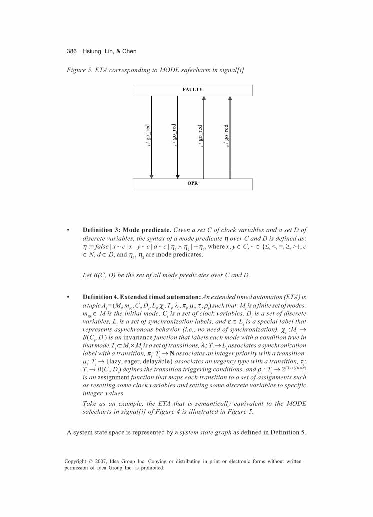
386 Hsiung, Lin, & Chen
Copyright © 2007, Idea Group Inc. Copying or distributing in print or electronic forms without writtenpermission of Idea Group Inc. is prohibited.
• Definition 3: Mode predicate. Given a set C of clock variables and a set D ofdiscrete variables, the syntax of a mode predicate η over C and D is defined as:η := false | x ~ c | x - y ~ c | d ~ c | η1 ∧ η2 | ¬η1, where x, y ∈ C, ~ ∈ {≤, <, =, ≥, >}, c∈ N, d ∈ D, and η1, η2 are mode predicates.
Let B(C, D) be the set of all mode predicates over C and D.
• Definition 4. Extended timed automaton: An extended timed automaton (ETA) isa tuple Ai = (Mi, mi0, Ci, Di, Li, χi, Ti, λi, πi, µi, τi, ρi) such that: Mi is a finite set of modes,mi0 ∈ M is the initial mode, Ci is a set of clock variables, Di is a set of discretevariables, Li is a set of synchronization labels, and ε ∈ Li is a special label thatrepresents asynchronous behavior (i.e., no need of synchronization), χi :Mi →B(Ci, Di) is an invariance function that labels each mode with a condition true inthat mode,Ti ⊆ Mi × Mi is a set of transitions, λi: Ti → Li associates a synchronizationlabel with a transition, πi: Ti → N associates an integer priority with a transition,µi: Ti → {lazy, eager, delayable} associates an urgency type with a transition, τi:Ti → B(Ci, Di) defines the transition triggering conditions, and ρi : Ti → 2Ci ∪ (Di ×N)
is an assignment function that maps each transition to a set of assignments suchas resetting some clock variables and setting some discrete variables to specificinteger values.Take as an example, the ETA that is semantically equivalent to the MODEsafecharts in signal[i] of Figure 4 is illustrated in Figure 5.
A system state space is represented by a system state graph as defined in Definition 5.
Figure 5. ETA corresponding to MODE safecharts in signal[i]
FAULTY
OPR
l / g
o_re
d
s / g
o_re
d
l / g
o_re
d
s / g
o_re
d

Safecharts Model Checking 387
Copyright © 2007, Idea Group Inc. Copying or distributing in print or electronic forms without writtenpermission of Idea Group Inc. is prohibited.
• Definition 5: System state graph. Given a system S with n components modeledby Ai = (Mi, mi0, Ci, Di, Li, χi, Ti, λi, πi, µi, τi, ρi), 1 ≤ i ≤ n, the system model is definedas a state graph represented by A1 × … × An = AS = (M, m0, C, D, L, c, T, l, π, µ, τ, ρ),where:� M=M1 × M2 × …× Mn is a finite set of system modes, m=m1.m2…..mn ∈ M,� m0=m1
0.m20…..mn
0 ∈ M is the initial system mode,� C=∪i Ci is the union of all sets of clock variables in the system,� D=∪i Di is the union of all sets of discrete variables in the system,� L=∪i Li is the union of all sets of synchronization labels in the system,� χ: M → B(∪i Ci, ∪i Di), χ (m)=∧i χi(mi), where m=m1.m2.....mn ∈ M.� T ⊆ M × M is a set of system transitions which consists of two types of
transitions:� Asynchronous transitions: ∃ i, 1 ≤ i ≤ n, ei ∈ Ti such that ei = e ∈ T� Synchronized transitions: ∃ i, j, 1 ≤ i ≠ j ≤ n, ei ∈ Ti, ej ∈ Tj such that λi(ei)
= (l, in), λj(ej) = (l, out), l ∈ Li ∩ Lj ≠ ∅, e ∈ T is synchronization of ei andej with conjuncted triggering conditions and union of all transitionsassignments (defined later in this definition)
� λ: T → L associates a synchronization label with a transition, whichrepresents a blocking signal that was synchronized, except for ε ∈ L, ε is aspecial label that represents asynchronous behavior (i.e., no need ofsynchronization),
� π: T → N associates an asynchronous transition with its original priority,and a synchronous transition with the maximum priority among all thesynchronized transitions,
� µ: T → {lazy, eager, delayable} associates an asynchronous transition withits original urgency type and a synchronous transition with the eager typeif there is one synchronized, or with the delayable type if there is one,otherwise with the lazy type,
� τ : T → B(∪i Ci, ∪i Di), τ (e)= τi(ei) for an asynchronous transition and τ (e)=τi(ei) ∧τj(ej) for a synchronous transition, and
� ρ: T → 2∪i Ci ∪ (∪i Di × N), ρ(e) = ρi(ei) for an asynchronous transition and ρ(e) =ρi(ei) ∪ρj(ej) for a synchronous transition.
• Definition 6. Safety-critical system. A safety-critical system is defined as a set ofresource components and consumer components. Each component is modeled byone or more safecharts. If a safety-critical system H has a set of resourcecomponents {R1, R2, …, Rm} and a set of consumer components {C1, C2, …, Cn}, His modeled by {ZR1, ZR2, …, ZRm, ZC1, ZC2, …, ZCn}, where ZX is a safechart model forcomponent X. Safecharts ZRi and ZCj are transformed into corresponding ETA ARiand ACj, respectively. Therefore, H is semantically modeled by the state graph AR1× …× ARm × AC1 × …× ACn as defined in Definition 5.
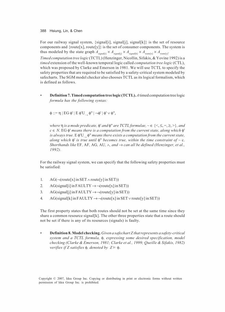
388 Hsiung, Lin, & Chen
Copyright © 2007, Idea Group Inc. Copying or distributing in print or electronic forms without writtenpermission of Idea Group Inc. is prohibited.
For our railway signal system, {signal[i], signal[j], signal[k]} is the set of resourcecomponents and {route[x], route[y]} is the set of consumer components. The system isthus modeled by the state graph Asignal[i] × Asignal[j] × Asignal[k] × Aroute[x] × Aroute[y].Timed computation tree logic (TCTL) (Henzinger, Nicollin, Sifakis, & Yovine 1992) is atimed extension of the well-known temporal logic called computation tree logic (CTL),which was proposed by Clarke and Emerson in 1981. We will use TCTL to specify thesafety properties that are required to be satisfied by a safety-critical system modeled bysafecharts. The SGM model checker also chooses TCTL as its logical formalism, whichis defined as follows.
• Definition 7. Timed computation tree logic (TCTL). A timed computation tree logicformula has the following syntax:
φ ::= η | EG φ' | E φ'U~ c φ'' | ¬φ' | φ' ∨ φ'',
where η is a mode predicate, φ' and φ'' are TCTL formulae, ~ ∈ {<, ≤, =, ≥, >}, andc ∈ N. EG φ' means there is a computation from the current state, along which φ'is always true. E φ'U~ c φ'' means there exists a computation from the current state,along which φ' is true until φ'' becomes true, within the time constraint of ~ c.Shorthands like EF, AF, AG, AU, ∧, and → can all be defined (Henzinger, et al.,1992).
For the railway signal system, we can specify that the following safety properties mustbe satisfied:
1. AG(¬(route[x] in SET ∧ route[y] in SET))2. AG(signal[i] in FAULTY → ¬(route[x] in SET))3. AG(signal[j] in FAULTY → ¬(route[y] in SET))4. AG(signal[k] in FAULTY → ¬(route[x] in SET ∨ route[y] in SET))
The first property states that both routes should not be set at the same time since theyshare a common resource signal[k]. The other three properties state that a route shouldnot be set if there is any of its resources (signals) is faulty.
• Definition 8. Model checking. Given a safechart Z that represents a safety-criticalsystem and a TCTL formula, φ, expressing some desired specification, modelchecking (Clarke & Emerson, 1981; Clarke et al., 1999; Queille & Sifakis, 1982)verifies if Z satisfies φ, denoted by Z ��φ.

Safecharts Model Checking 389
Copyright © 2007, Idea Group Inc. Copying or distributing in print or electronic forms without writtenpermission of Idea Group Inc. is prohibited.
Model checking can be either explicit using a labeling algorithm or symbolic using a fix-point algorithm. Binary decision diagram (BDD) and difference bound matrices (DBM)are data structures used for Boolean formulas and clock zones (Clarke et al., 1999),respectively. For our railway signal system, we must check if Asignal[i] × Asignal[j] × Asignal[k]× Aroute[x] × Aroute[y] � φ, where φ is each of the four properties described above.
Model Checking Safecharts
Safecharts have been used to model safety-critical systems, but the models have neverbeen verified. In this work, we propose a method to verify safety-critical systems modeledby safecharts. Our target model checker is state graph manipulators (SGM) (Hsiung &Wang, 1998; Wang & Hsiung, 2002), which is a high-level model checker for both real-time systems, as well as, Systems-on-Chip modeled by a set of extended timed automata.There are several issues to be resolved in model checking safecharts.In the course of developing a model-based verification method for safety-criticalsystems, several issues are encountered as detailed in the following. First, we need todecide how to model safety-critical systems. Our decision is to adopt safecharts(Dammag & Nissanke, 1999) as our models. Safecharts are a variant of statecharts,especially for use in the specification and the design of safety-critical systems. Theobjective of the model is to provide a sharper focus on safety issues and a systematicapproach to deal with them. This is achieved in safecharts by making a clear separationbetween functional and safety requirements. Other issues encountered in designing theformal verification methodology for model-based safety-critical systems are as follows:
• How to transform safecharts into a semantically equivalent Extended TimedAutomata (ETA) model that can be accepted by traditional model checkers? Howcan the transformation preserve the safety semantics in safecharts?
• What are the properties that must be specified for model checking safecharts?• Basic states in safecharts have a risk relation with each other specifying the
comparative risk/safety levels. Safety non-determinism allows only safe transi-tions between states with known risk levels in safecharts. How do we representsuch information in ETA for model checking?
• The current semantics of safecharts states that mutual exclusion of resourceusages can be achieved through priority. This is clearly insufficient, as prioritiescannot ensure mutual exclusion.
Briefly, our solutions to the above-mentioned issues can be summarized as follows:
• Flattening and safety semantics: To transform safecharts into ETA one has to takecare of two things, namely, flattening the hierarchy in safecharts and combiningthe functional and safety transitions of safecharts, while preserving equivalence

390 Hsiung, Lin, & Chen
Copyright © 2007, Idea Group Inc. Copying or distributing in print or electronic forms without writtenpermission of Idea Group Inc. is prohibited.
to the safety semantics of safecharts. Urgent transitions are also implemented intoour model checker for this transformation.
• Functional property and safety constraint: The specification of functional prop-erties is the same as that in any conventional model checking such as using atemporal logic. However, properties corresponding to the safety constraints canbe specified in two ways according to the types of safety constraint.
• Risk band and transition priorities: Risk bands are automatically constructed andrisks associated with states. Nondeterminism in safecharts is resolved by priori-tizing transitions such that transitions leading to safer states are given higherpriorities. Risk levels and prioritization of transitions are implemented in our modelchecker using a novel clock zone subtraction operation.
• Resource access mechanisms: Resource allocation and de-allocation can bemodeled in safecharts, however mutual exclusion between resource usages cannotbe guaranteed in safecharts without importing modeling restrictions. In the sectionon Resource Access Mechanism, we will give an example to explain why this isimportant and describe modeling guidelines that designers need to follow formutual exclusivity of resource usages.
A system designer models a safety-critical system using a set of safecharts. Afteraccepting the safecharts, we transform them into ETA, while taking care of the safetycharacterizations in safecharts, and then automatically generate properties correspond-ing to the safety constraints. The SGM model checker is enhanced with transition priorityand urgency types. Resource access mechanisms in safecharts are also checked forsatisfaction of modeling restrictions that prevent violation of mutual exclusion. Finally,we input the translated ETA to SGM to verify the safety-critical system satisfiesfunctional and safety properties. Each of the issues encountered during implementationand the corresponding solutions are detailed in the rest of this section.
Flattening Safecharts and Safety Semantics
Our primary goal is to model check safecharts, a variant of statecharts. However,safecharts cannot be accepted as system model input by most model checkers, which canaccept only flat automata models such as the extended timed automata (ETA) acceptedby SGM. As a result, the state hierarchy and concurrency in safecharts must betransformed into semantically equivalent constructs in ETA. Further, besides thefunctional layer, safecharts have an extra safety layer, which must be transformed intoequivalent modeling constructs in ETA and specified as properties for verification.There are three categories of states in safecharts: OR, AND, and BASIC. An OR-state,or an AND-state, consists generally of two or more substates. Being in an AND-statemeans being in all of its substates simultaneously, while being in an OR-state meansbeing in exactly one of its substates. A BASIC-state is translated into an ETA mode. The

Safecharts Model Checking 391
Copyright © 2007, Idea Group Inc. Copying or distributing in print or electronic forms without writtenpermission of Idea Group Inc. is prohibited.
translations for OR-states and AND-states are performed as described in Lavazza (2001).Some of the details are given in the sections on implementation.
Safety Semantics
The syntax for the triggering condition and action of a transition in safecharts is: e [fcond]/ a [l, u) ψ [G], where e is the set of triggering events, fcond is the set of guard conditions,a is the set of broadcast events, [l, u) is the time interval specifying the time constraint,ψ means the execution conditions for safety constraints, and G is the set of safety-layer’sguards. In safecharts, e [fcond] / a appears in the functional layer, while [l, u) ψ [G] mayappear in the safety layer. The two layers of safecharts can be integrated into one in ETAas described in the following. However, we need to design three different types oftransitions (Altisen, Gössler, & Sifakis, 2002):
• Eager Evaluation (ε): Execute the action as soon as possible, that is, as soon as aguard is enabled. Time cannot progress when a guard is enabled.
• Delayable Evaluation (δ): Can put off execution until the last moment the guard istrue. Therefore, time cannot progress beyond a falling edge of guard.
• Lazy Evaluation (λ): You may or may not perform the action.
The transition condition and assignment e[fcond]/a [l, u) ψ[G] can be classified into threetypes as follows:
des(t)
src(t)
e[fcond]/a [G]
des(t)
src(t)
(e[fcond Λ ¬G] /a) λ
Figure 6. Transformation of prohibition evaluation
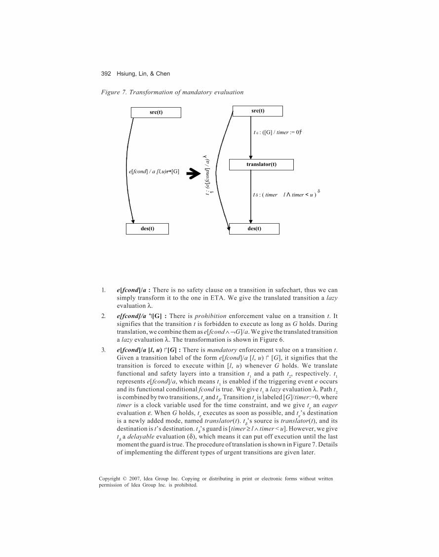
392 Hsiung, Lin, & Chen
Copyright © 2007, Idea Group Inc. Copying or distributing in print or electronic forms without writtenpermission of Idea Group Inc. is prohibited.
1. e[fcond]/a : There is no safety clause on a transition in safechart, thus we cansimply transform it to the one in ETA. We give the translated transition a lazyevaluation λ.
2. e[fcond]/a ↖[G] : There is prohibition enforcement value on a transition t. Itsignifies that the transition t is forbidden to execute as long as G holds. Duringtranslation, we combine them as e[fcond ∧ ¬G]/a. We give the translated transitiona lazy evaluation λ. The transformation is shown in Figure 6.
3. e[fcond]/a [l, u) ↗[G] : There is mandatory enforcement value on a transition t.Given a transition label of the form e[fcond]/a [l, u) ↗ [G], it signifies that thetransition is forced to execute within [l, u) whenever G holds. We translatefunctional and safety layers into a transition t1 and a path t2, respectively. t1represents e[fcond]/a, which means t1 is enabled if the triggering event e occursand its functional conditional fcond is true. We give t1 a lazy evaluation λ. Path t2is combined by two transitions, tε and tδ. Transition tε is labeled [G]/timer:=0, wheretimer is a clock variable used for the time constraint, and we give tε an eagerevaluation ε. When G holds, tε executes as soon as possible, and tε’s destinationis a newly added mode, named translator(t). tδ’s source is translator(t), and itsdestination is t’s destination. tδ’s guard is [timer ≥ l ∧ timer < u]. However, we givetδ a delayable evaluation (δ), which means it can put off execution until the lastmoment the guard is true. The procedure of translation is shown in Figure 7. Detailsof implementing the different types of urgent transitions are given later.
Figure 7. Transformation of mandatory evaluation
e[fcond] / a [l,u) [G]
des(t)
translator(t)
des(t)
src(t)
t : (e
[fcon
d] /
a)
t ε : ([G] / timer := 0)
λ
1
ε
t δ : ( timer � l Λ timer < u ) δ
src(t)

Safecharts Model Checking 393
Copyright © 2007, Idea Group Inc. Copying or distributing in print or electronic forms without writtenpermission of Idea Group Inc. is prohibited.
Property Specification for Safecharts
In the safety-layer of safecharts, there are two types of safety conditions on a transition,one is prohibition and the other is mandatory. After parsing the safechart models of asafety-critical system, corresponding properties are automatically generated withoutrequiring the user to specify again. Such properties are used to verify if the safety-layerswork or not. As described in the following, to ensure that the safety constraints areworking, two categories of properties are generated automatically for model checking.
1. AG (( src(t) ∧∧∧∧∧ G ) → ¬→ ¬→ ¬→ ¬→ ¬ EX(des(t))) : If a transition t in safechart has prohibitioncondition �[G] in its safety-layer, it means that such transition is forbidden toexecute as long as G holds. As shown in Figure 6, t’s source is src(t), and itsdestination is des(t). Due to �[G], src(t) is not allowed to transit to des(t) as longas G holds. If such property is tenable in our system state graph, which means thatthere is no transition from src(t) to des(t) executing whenever G holds, then we canknow that the safety-critical system will not become dangerous while G holds.
2. AG (( src(t) ∧∧∧∧∧ G → ¬→ ¬→ ¬→ ¬→ ¬ EX (¬¬¬¬¬ translator(t))) and AG(translator(t) ∧∧∧∧∧ timer < u) : Ifa transition t in safechart has [l, u) �[G] in its safety-layer, it means that suchtransition is enabled and forced to execute within [l, u) whenever G holds. Asmentioned in former sections, we add two transitions for the safety-layer’sbehavior, namely tε and tδ, and a mode, translator(t) between them. From Figure 7,when G holds, tε must be executed as soon as possible due to its eager evaluationand the next active mode must be translator(t). Moreover, we know that if the modetranslator(t) is active, then the next active state must be des(t) within the time limittimer ≥ l ∧ timer < u. If this constraint is violated, then the safety condition will notbe satisfied.
By the first category, we can ensure that a safety-critical system will not be dangerousunder certain prohibited conditions. By the second category described above, we cancheck if a safety-critical system with some faults or malfunctions will go to a safersituation that can deal with such faults or violates the time limits.
Transition Priority
When modeling safety-critical systems, it is important to eliminate any nondeterministicbehavior patterns of the system. Nondeterminism arises if the triggering expressions oftwo transitions starting from a common state are simultaneously fulfilled. Because of itsconcern with safety-critical systems, safecharts remove non-determinism in all casesexcept when there is no safety implication. In the safechart model, we use a list of riskrelation tuples to establish a risk graph (Nissanke & Dammag, 2000) of this safechart.Noncomparable conditions may still exist in a risk graph. An example is given in Figure8, where, relative to other states, the state O may have received less attention in the riskassessment, resulting in it becoming non-comparable with other states in the graph,
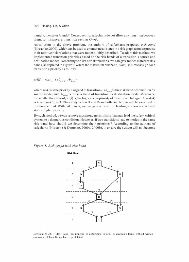
394 Hsiung, Lin, & Chen
Copyright © 2007, Idea Group Inc. Copying or distributing in print or electronic forms without writtenpermission of Idea Group Inc. is prohibited.
namely, the states N and P. Consequently, safecharts do not allow any transition betweenthem, for instance, a transition such as O→P.As solution to the above problem, the authors of safecharts proposed risk band(Nissanke, 2000), which can be used to enumerate all states in a risk graph to make precisetheir relative risk relations that were not explicitly described. To adopt this method, weimplemented transition priorities based on the risk bands of a transition’s source anddestination modes. According to a list of risk relations, we can give modes different riskbands, as depicted in Figure 8, where the maximum risk band, maxrb, is 6. We assign eachtransition a priority as follows:
pri(t) = maxrb - ( rbsrc(t) - rbdes(t)),
where pri(t) is the priority assigned to transition t, rbsrc(t) is the risk band of transition t’ssource mode, and rbdes(t) is the risk band of transition t’s destination mode. Moreover,the smaller the value of pri(t) is, the higher is the priority of transition t. In Figure 8, pri(t4)is 4, and pri(t6) is 3. Obviously, when t4 and t6 are both enabled, t6 will be executed inpreference to t4. With risk bands, we can give a transition leading to a lower risk bandstate a higher priority.By such method, we can remove most nondeterminisms that may lead the safety-criticalsystem to a dangerous condition. However, if two transitions lead to modes in the samerisk band how should we determine their priorities? According to the authors ofsafecharts (Nissanke & Dammag, 2000a, 2000b), to ensure the system will not become
Figure 8. Risk graph with risk band
M
N O
P
Q
S R
T
Risk Band
6
5
4
3
2
1
t1 t2
t3 t4
t5
t7 t8
t9 t10

Safecharts Model Checking 395
Copyright © 2007, Idea Group Inc. Copying or distributing in print or electronic forms without writtenpermission of Idea Group Inc. is prohibited.
dangerous, one has to look for the risk bands of the two transitions’ future targets. Whenthe risk bands of their future targets are different, one should give the one leading to alower risk band eventually higher priority and the other lower priority. In our implemen-tation, when a state has two or more transitions with the same priority, we use a recursivecall to modify the transitions’ priorities by checking the risk bands of future targets ifthe risk bands of future targets are different. For example, in Figure 8, initially t1 and t2are assigned the same priority, 5. After we find that M has two transitions with the samepriority, we continue to check their future targets. As a result, we come to know that t2will lead to a safer condition in the future, thus we give t2 a higher priority than t1. In Figure8, Q has two transitions t7 and t8, both of which lead to T. Thus, we have no need to modifytheir original priority, 5.For implementing transition priorities into the SGM model checker, the triggering guardsof a transition are modified as follows (Altisen, 2002):
t '(ti) = ∧π(tj)>π(ti) ¬τ (tj) ∧τ (ti)
where τ(ti) and τ(tj) are the guard conditions of transitions ti and tj, π(tj) > π(ti) means thatthe priority of tj is higher than that of ti, and t '(ti) is the modified guard condition of ti. Thisapplication results in allowing ti executed only if there is no enabled transition tj that haspriority over ti.
Resource Access Mechanisms
Safecharts model both consumers and resources. However, when resources must beused in a mutually exclusive manner, a model designer may easily violate the mutualexclusion restriction by simultaneous checking and discovery of free resources, followedby their concurrent usages. A motivational example can be observed in the railwaysignaling system as illustrated in Figure 2, Figure 3, and Figure 4, where signal[k] mustbe shared in a mutually exclusive way between route[x] and route[y]. However, each routechecks if signal[k] is free and finds it free, then both route will be SET, assuming G doesnot hold. This is a modeling trap that violates mutually exclusive usages of resources.A serious tragedy could happen in this application example as two intersecting routesare set resulting in perhaps a future train collision.From above we know that when consumers try to acquire resources that cannot be usedconcurrently, it is not safe to check only the status of resources. We need some kind ofmodel-based mutual exclusion mechanism. A very simple policy would be like Fischer’smutual exclusion protocol (Larsen, Steffen, & Weise, 1996). For each mutually exclusiveresource, a variable is used to record the id of the consumer currently using the resource.Before the consumer uses the resource, it has to check if the variable is set to its id. Figure9 is a corrected variant of the route safechart from Figure 3. When route[id] transits intoEVALUATE_REQ, it sets variable reg to its id. When route[x] tries to transit into the SETmode to acquire the usage of resource, it needs to check if reg is still its id. If reg is stillx, then route[x] acquires the usage of the resource. Other mechanisms such as atomic

396 Hsiung, Lin, & Chen
Copyright © 2007, Idea Group Inc. Copying or distributing in print or electronic forms without writtenpermission of Idea Group Inc. is prohibited.
test-and-set performed on a single asynchronous transition can also achieve mutualexclusion.
Implementation in a Model Checker
The model checking of safecharts has been implemented in the state-graph manipulators(SGM), which is a TCTL model checker for real-time systems such as communicationprotocols, systems-on-chips, and embedded systems. SGM was a conventional modelchecker that could take only a set of ETA as the system model. We enhanced SGM inseveral ways to accommodate the verification of safecharts. First, we had to develop aninput language that could allow recursive definitions of the hierarchical safechartsmodels. Second, we had to employ a flattening algorithm to remove all the hierarchies andobtain a set of ETA that was semantically equivalent to the originally specified set ofsafecharts. Third, the preservation of safety semantics from safecharts to ETA demandedthe support for transition urgencies such as eager and delayable, besides the original lazysemantics. We implemented support for transition urgencies in SGM through a novelzone capping operation. Finally, we had to develop and implement algorithms for theconstruction of risk bands from the risk relations specified in safecharts and then use therisk levels as the risk associated with the ETA states. We had to also check if there areany transitions between states with unknown risk levels. For implementing safe non-
Figure 9. Safechart for route[x] with mutual exclusion
route[x]
SET
EVALUATE_REQ
NOT_SET
Return_route[0,2]�[signal[i] in signal[i] in FREE ∧ signal[k] FAULTY ∨ signal[k] in FAULTY] in FREE ∧ regi=x ∧ regk=x / release_i, release_k �[signal[i] in FAULTY ∨ signal[k] in FAULTY]
/ allocate_i, allocate_k
reject_route ∨ regi? x ∨ regk ? x �[signal[i] in FAULTY ∨ signal[k] in FAULTY]
request_route / regi := x,regk := x

Safecharts Model Checking 397
Copyright © 2007, Idea Group Inc. Copying or distributing in print or electronic forms without writtenpermission of Idea Group Inc. is prohibited.
determinism we had to support prioritized transitions in SGM, which we accomplishedusing a clock zone subtraction operation. All the four parts of SGM enhancements aredescribed in greater detail in the rest of this section.
Safecharts Input Syntax
We developed our input language for the specification of safecharts and a parser for thelanguage. The language syntax is recursive because a safechart can have other safechartsin a lower hierarchy such as that for an AND or an OR state in a safechart. Each safechartswas required to be specified as one of the following: AND, OR, or BASIC. We made nodistinction between a state and a safechart. Risk relations were specified for basicsafecharts only. In the language, we allowed each outgoing transition from a safechartto have two layers: functional and safety. The safety version of a transition was to bespecified only if required. A simple example can be seen from the following piece of inputfile for the railway signal system.
safechart signal[i] := AND[MODE, LAMP, COLOR, SENSOR, STATUS]{
safechart MODE := OR[]{
initially OPR;safechart FAULTY := BASIC{
functional:when sync repairL may goto OPR;when sync repairS may goto OPR;
safety:}Safechart OPR := BASIC{ … }
}……
}
Flattening Safecharts into ETA
Safecharts, like UML statecharts, have three kinds of states: AND, OR, and BASIC. AnAND state has two or more parallel safecharts and an OR state represents anothersafechart. Thus, there is concurrency and hierarchy embedded within a safechart, whichmust be represented into a flattened model such as ETA for model checking so that SGMcan be used to verify safecharts.

398 Hsiung, Lin, & Chen
Copyright © 2007, Idea Group Inc. Copying or distributing in print or electronic forms without writtenpermission of Idea Group Inc. is prohibited.
The flattening procedure that was implemented into SGM has been adapted from(Lavazza, 2001) for safecharts such that besides representing concurrency and hierarchyinto ETA, safety semantics were also transformed and preserved from safecharts intoETA. We give a brief account of the representation of concurrency and hierarchy in thissection and discuss safety semantics in the next section.As shown in Figure 10, concurrency was represented as follows. Each safechart in anAND state was represented by an ETA. Except for a topmost level AND state, for all otherAND states in the other levels, each generated ETA has an extra initial state and atransition from the initial state to the original initial state in the corresponding safechart.In Figure 10, A0 and B0 are the two newly introduced states in the corresponding ETA.The reason for introducing the new initial state is that any transition leading into an ANDstate must be such that all the safecharts in the AND state start from their original initialstates simultaneously. In the ETA representing the parent safechart of an AND state, thetransition leading into the AND state is synchronized with all the transitions outgoingfrom the new initial states of the corresponding ETA, for example, tin. When an AND stateis exited, all corresponding ETAs return to their respective newly introduced initial statesto wait for the next transition into the AND state and simultaneous entries into respectiveoriginal initial states. For each transition exiting from an AND state in a safechart, a setof transitions must be introduced from each state of each ETA to the ETA’s new initialstate. In the ETA representing the parent safechart of an AND state, the transition exitingfrom the AND state is synchronized with all the corresponding transitions in all the ETArepresenting the safecharts in the AND state, for example, tout.As shown in Figure 11, hierarchy was represented as follows. Rather than representingthe safechart in an OR state by a separate ETA, we chose to embed the ETA into the ETAthat represents the parent safechart. This approach reduces the number of ETAgenerated and the inherent parallelism of the generated set of ETA. However, we have
Figure 10. Representing concurrency in ETA
A1
A2
B1
B2
tin
tout
A1
A2
B1
B2
A0 B0
tin tin tout
tout
tout
tout
AND state in Safechart ETA models
tin
tout
X
X

Safecharts Model Checking 399
Copyright © 2007, Idea Group Inc. Copying or distributing in print or electronic forms without writtenpermission of Idea Group Inc. is prohibited.
to carefully represent the transitions leading into and exiting from an OR state. For eachtransition leading into an OR state, an ETA transition must be introduced from the sourcestate of the transition to the initial state of the embedded ETA representing the OR state,for example, tin. For each transition exiting from an OR state, a set of ETA transitions mustbe introduced such that there is a transition from each state of the embedded ETA to thedestination state of the transition, for example, tout. This generates a large number oftransitions; however, this is inevitable just as a system reset behavior can allow a systemto transit from any state it is currently in to the initial state of the system. For all othertransitions leading into or exiting from some specific state within the OR state, acorresponding ETA transition can be introduced between the two specific states in thefinal ETA generated. Currently, we do not support history states, that is, return to thestate within an OR state from which the OR state was exited the last time. This is due tothe limited expressiveness of ETA compared to safecharts.
Supporting Transition Urgencies
For enforcement of safety constraints such as the mandatory transitions represented by[l, u) �[G], it was described in Section 4.1 that we need to support transition urgenciesin the SGM model checker. However, SGM takes timed automata as system models andtimed automata assume a lazy semantics for transitions, that is, a transition may or maynot be taken when its triggering condition is satisfied. To support urgency semantics,we need to force a transition to be taken by some deadline (as soon as an eager transitionis enabled or before a delayable transition is disabled after being enabled). Given theexpressiveness of ETA, we can only use state invariants to force transitions to be takenfrom a state. The transition deadline implies some time point in the future and time is
Figure 11. Representing hierarchy in ETA
A1
A2
tin
tout
X_A1
X_A2
tin
tout
OR state in Safechart ETA model
X
tout
Y Y
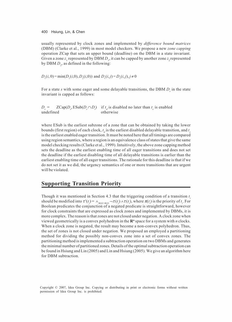
400 Hsiung, Lin, & Chen
Copyright © 2007, Idea Group Inc. Copying or distributing in print or electronic forms without writtenpermission of Idea Group Inc. is prohibited.
usually represented by clock zones and implemented by difference bound matrices(DBM) (Clarke et al., 1999) in most model checkers. We propose a new zone cappingoperation ZCap that sets an upper bound (deadline) on the DBM in a state invariant.Given a zone z1 represented by DBM D1, it can be capped by another zone z2 representedby DBM D2, as defined in the following:
D1(i, 0) = min(D1(i,0), D2(i,0)) and D1(i, j) = D1(i, j), j ≠ 0
For a state s with some eager and some delayable transitions, the DBM Ds in the stateinvariant is capped as follows:
Ds = ZCap(Ds, ESub(Ds ∩ Dt) if td is disabled no later than te is enabledundefined otherwise
where ESub is the earliest subzone of a zone that can be obtained by taking the lowerbounds (first region) of each clock, td is the earliest disabled delayable transition, and teis the earliest enabled eager transition. It must be noted here that all timings are comparedusing region semantics, where a region is an equivalence class of states that give the samemodel checking results (Clarke et al., 1999). Intuitively, the above zone capping methodsets the deadline as the earliest enabling time of all eager transitions and does not setthe deadline if the earliest disabling time of all delayable transitions is earlier than theearliest enabling time of all eager transitions. The rationale for this deadline is that if wedo not set it as we did, the urgency semantics of one or more transitions that are urgentwill be violated.
Supporting Transition Priority
Though it was mentioned in Section 4.3 that the triggering condition of a transition tishould be modified into τ '(ti) = ∧π(tj)>π(ti) ¬τ (tj) ∧τ (ti), where π(ti) is the priority of ti. ForBoolean predicates the conjunction of a negated predicate is straightforward, howeverfor clock constraints that are expressed as clock zones and implemented by DBMs, it ismore complex. The reason is that zones are not closed under negation. A clock zone whenviewed geometrically is a convex polyhedron in the Rn space for a system with n clocks.When a clock zone is negated, the result may become a non-convex polyhedron. Thus,the set of zones is not closed under negation. We proposed an employed a partitioningmethod for dividing the possibly non-convex zone into a set of convex zones. Thepartitioning method is implemented a subtraction operation on two DBMs and generatesthe minimal number of partitioned zones. Details of the optimal subtraction operation canbe found in Hsiung and Lin (2005) and Lin and Hsiung (2005). We give an algorithm herefor DBM subtraction.
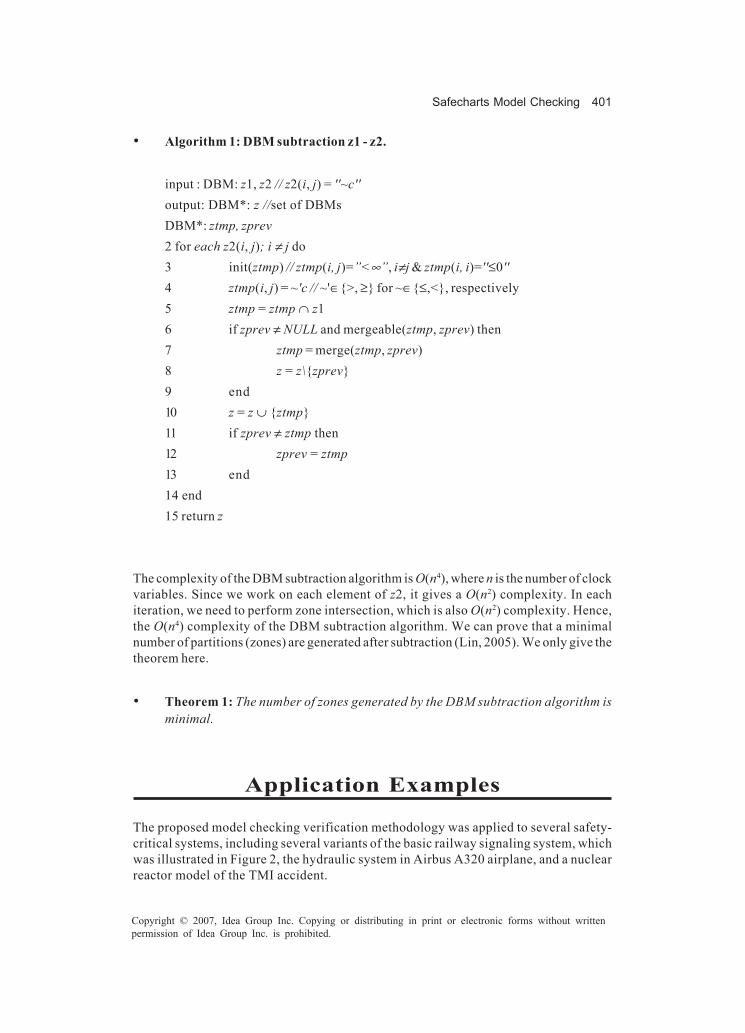
Safecharts Model Checking 401
Copyright © 2007, Idea Group Inc. Copying or distributing in print or electronic forms without writtenpermission of Idea Group Inc. is prohibited.
• Algorithm 1: DBM subtraction z1 - z2.
input : DBM: z1, z2 // z2(i, j) = ''~c''output: DBM*: z //set of DBMsDBM*: ztmp, zprev2 for each z2(i, j); i ≠ j do3 init(ztmp) // ztmp(i, j)=”<∞”, i≠j & ztmp(i, i)=''≤0''4 ztmp(i, j) = ~'c // ~'∈{>, ≥} for ~∈{≤,<}, respectively5 ztmp = ztmp ∩ z16 if zprev ≠ NULL and mergeable(ztmp, zprev) then7 ztmp = merge(ztmp, zprev)8 z = z\{zprev}9 end10 z = z ∪ {ztmp}11 if zprev ≠ ztmp then12 zprev = ztmp13 end14 end15 return z
The complexity of the DBM subtraction algorithm is O(n4), where n is the number of clockvariables. Since we work on each element of z2, it gives a O(n2) complexity. In eachiteration, we need to perform zone intersection, which is also O(n2) complexity. Hence,the O(n4) complexity of the DBM subtraction algorithm. We can prove that a minimalnumber of partitions (zones) are generated after subtraction (Lin, 2005). We only give thetheorem here.
• Theorem 1: The number of zones generated by the DBM subtraction algorithm isminimal.
Application Examples
The proposed model checking verification methodology was applied to several safety-critical systems, including several variants of the basic railway signaling system, whichwas illustrated in Figure 2, the hydraulic system in Airbus A320 airplane, and a nuclearreactor model of the TMI accident.
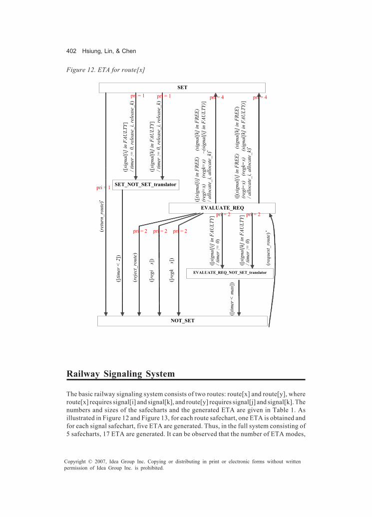
402 Hsiung, Lin, & Chen
Copyright © 2007, Idea Group Inc. Copying or distributing in print or electronic forms without writtenpermission of Idea Group Inc. is prohibited.
Railway Signaling System
The basic railway signaling system consists of two routes: route[x] and route[y], whereroute[x] requires signal[i] and signal[k], and route[y] requires signal[j] and signal[k]. Thenumbers and sizes of the safecharts and the generated ETA are given in Table 1. Asillustrated in Figure 12 and Figure 13, for each route safechart, one ETA is obtained andfor each signal safechart, five ETA are generated. Thus, in the full system consisting of5 safecharts, 17 ETA are generated. It can be observed that the number of ETA modes,
Figure 12. ETA for route[x]
SET
EVALUATE_REQ
NOT_SET
SET_NOT_SET_translator
EVALUATE_REQ_NOT_SET_translator
([(s
igna
l[i]
in F
REE)
(sig
nal[k
] in
FREE
)
(reg
i=x)
(reg
k=x)
(sig
nal[
k] in
FAU
LTY)
] / a
lloca
te_i
, allo
cate
_k)•
([(s
igna
l[i] i
n FR
EE)
(sig
nal[
k] in
FRE
E)
(reg
i=x)
(reg
k=x)
~(sig
nal[i
] in
FAU
LTY)
] / a
lloca
te_i
, allo
cate
_k)•
(req
uest
_rou
te) •
([si
gnal
[k] i
n FA
ULT
Y ]
/ tim
er :=
0)
([si
gnal
[i] i
n FA
ULT
Y ]
/ tim
er :=
0)
([tim
er <
max
]) (rej
ect_
rout
e )
([reg
i x
])
([reg
k x
])
([si
gnal
[i] i
n FA
ULT
Y ]
/ tim
er :=
0, r
elea
se_i
, rel
ease
_k)
([si
gnal
[k] i
n FA
ULT
Y ]
/ tim
er :=
0, r
elea
se_i
, rel
ease
_k)
([tim
er <
2])
(ret
urn_
rout
e )•
pri = 1
pri = 1 pri = 1 pri = 4 pri = 4
pri = 2 pri = 2
pri = 2 pri = 2 pri = 2

Safecharts Model Checking 403
Copyright © 2007, Idea Group Inc. Copying or distributing in print or electronic forms without writtenpermission of Idea Group Inc. is prohibited.
40, is lesser than the number of safecharts states, 56. The reason for this reduction is thathierarchical states do not exist in ETA. The mutual exclusion issues were both resolvedfor this railway system.As illustrated in the figures given in the Appendix, a number of variants of the basicrailway signaling system were used for validating the proposed method’s scalability andefficiency. Varying the number of routes and the number of signals in each routeincreases the complexity and the concurrency of the system. However, we can observefrom the verification results in Table 2 that the amount of time and memory expended forverification do not increase exponentially and are very well acceptable. The number ofproperties to be verified also increases and thus their automatic generation is a crucialstep for successful and easily accessible verification of safety critical systems. Thenumber of issues solved implies how the proposed solutions in this work are significantfor the successful verification of complex systems modeled by safecharts. The safetyproperties that were verified for these railway-signaling systems are as given previouslyafter TCTL was defined.
Figure 13. Five ETA for each signal[i] safechart
FAULTY
OPR
L_OUT
L_IN
l / g
o_re
d
MODE ETA LAMP ETA
s / g
o_re
d
l / g
o_re
d
s / g
o_re
d
l l
RED
go_r
ed
go_g
reen
COLOR ETA
GREEN
SENSOR ETA
S_OUT
s s
S_IN
BUSY
FREE
rele
ase_
i/ go
_red
allo
cate
_i
STATUS ETA
Component Safecharts ETA
Name |S| |T| # |M| |T|
route[x] 4 7 1 5 13
route[y] 4 7 1 5 13
signal[i] 16 16 5 10 16
signal[j] 16 16 5 10 16
signal[k] 16 16 5 10 16
full system 56 62 17 40 74
Table 1. Results of the railway signaling system

404 Hsiung, Lin, & Chen
Copyright © 2007, Idea Group Inc. Copying or distributing in print or electronic forms without writtenpermission of Idea Group Inc. is prohibited.
Airbus A320 Hydraulic System
The hydraulic system in an advanced airplane such as Airbus A320 supplies hydraulicpower for aircraft control during flight and on-ground (Bieber, 2002). The safetyrequirements are as follows: (1) we need to ensure that we are not in a state of total lossof hydraulic power, which is classified as catastrophic; (2) we need to verify that a singlefailure does not result in total loss of power. As shown in Figure 14, there are three kindsof pumps: electric motor pump (EMP) powered by the electric system, engine driven pump(EDP) powered by the two aircraft engines, and one RAT pump powered by RAM airturbine. There are three power distribution channels: Green, Blue, and Yellow. The Bluechannel is made up of one electric pump EMPb, one RAT pump, and a distribution line
System safecharts ETA |φ| Issues Solved
Time Mem
|R| |S| # |S| |T| # |M| |T| ME (µs) (MB)
A 2 3(1) 5 56 62 17 40 74 20 1 230 0.12
B 2 4(1) 6 72 81 22 50 94 25 1 292 0.12
C 2 4(2) 6 72 84 22 50 98 30 2 337 0.13
D 3 4(1) 7 76 85 23 55 103 30 1 326 0.14
E 3 5(2) 8 92 110 28 65 131 45 2 515 0.14
F 4 5(1) 9 96 108 29 70 132 40 1 634 0.14
Table 2. Results of application examples
Figure 14. A320 hydraulic system model
eng1_ctl
eng2_ctl
empb_ctl
eng1
eng2
elec1 empy_ctl
rat_ctl
elec2
RAT
EMPb
EMPy
EDPg
EDPy
distg
disty
distb
PTU

Safecharts Model Checking 405
Copyright © 2007, Idea Group Inc. Copying or distributing in print or electronic forms without writtenpermission of Idea Group Inc. is prohibited.
distb. The Green channel is made up of one pump driven by engine 1 EDPg and adistribution line distg. The Yellow channel is made up of one pump driven by engine 2EDPy, one electric pump EMPy, and a distribution line disty. A power transfer unit PTUopens a transmission from green hydraulic power to yellow distribution line and viceversa as soon as the differential pressure between both channels is higher than a giventhreshold.There are two types of models in this system, namely basic block and controller block.Each basic block was modeled by a safechart with a MODE OR state representing if it isworking or faulty, a SENSOR OR state modeling its sensor, and an OUTPUT OR stateshowing if the basic block is providing hydraulic power. Each controller block, besidesthe MODE and SENSOR states, also has a STATUS OR state representing if the systemis on ground or in flight, and an OUTPUT state representing if it is currently activatedor not. As we can see, the failure modes for each component block are explicitly modeledinto safecharts, thus eliminating the need to separately define the failure modes andeffects. Figure 15 shows the generic model for a basic block and Figure 16 shows thegeneric model for a controller block.Safecharts modeled each of the five pumps and their corresponding controllers, alongwith the three distribution lines. However, since the blue system is independent of theother two systems, we verified the blue system separately. To check for total loss ofhydraulic power, we had to check if the blue system does not supply power (i.e., EF (EG(powerB = 0))) and if the rest of the system (green and yellow systems) also does notsupply power (i.e., EF (EG(powerG = 0 & powerY = 0))). It was easy to check the secondsafety requirement, that is, if a single failure results in total loss of hydraulic power, whichexpressed in TCTL is EF(EG(MODE in fail => powerB=0 & powerG=0 & powerY=0)).In this A320 hydraulic system model, there were 13 safecharts with 145 states and 105transitions, which were automatically transformed into 44 ETA models with 98 modes and125 transitions.
Nuclear-Reactor System
The Three Mile Island 2 Nuclear Reactor was also modeled to see if we could verify thefailure that occurred during the accident on 28th March, 1979. As shown in Figure 17, thereare two circuits: a primary circuit and a secondary circuit. The primary circuit (Nissanke,2002) generated steam due to the reactor heat and was confined in a containment buildingto avoid the leakage of radiation. A pressurizer valve and some control rods controlledthe nuclear reaction. The secondary circuit fed water to the primary circuit for coolingand heat exchange and used the steam generated from the primary circuit to drive aturbine.We summarize the events that led to the TMI accident as follows. Due to some manualerrors, the feedwater valve in the secondary circuit was closed; heat exchange was thusstopped, resulting in a temperature increase in the primary circuit. As expected, thepressure relief valve (PRV) was opened and the control rods were dropped to slow downthe nuclear fission. This is the loss of coolant accident (LOCA). When the pressure andtemperature dropped, the PRV should have closed and control rods lifted. However, the

406 Hsiung, Lin, & Chen
Copyright © 2007, Idea Group Inc. Copying or distributing in print or electronic forms without writtenpermission of Idea Group Inc. is prohibited.
PRV was stuck open and this was not detected by the solenoid (sensor). As a result, thecoolant from the primary circuit kept draining, thus endangering its environment withpossible radiation.Safecharts can be used to model the components in the TMI nuclear reactor and sincesafecharts can explicitly model all the failure modes of a component such as the stuck-open failure more of the PRV we can use safecharts to check for such safety violationsin the model itself. Figure 18 illustrates the safechart model for PRV, where we can seethat the sensor in the model detects PRV stuck-open failure, however, in the actual TMIreactor, during the accident, the PRV-close transition was taken, and thus the sensorcould not detect the failure of the PRV to close. Figure 19 illustrates the safechart modelfor the primary circuit in the TMI nuclear reactor along with LOCA. The hazard that waschecked for this model is EF (status in stuck-opened & sensor in prv-closed & flow instopped). Any witness to the satisfaction of this TCTL property generated by the SGMmodel checker was evidence that the hazard could happen in this model. There were twosafecharts with 27 states and 28 transitions, which were transformed into 6 ETA modelswith 19 modes and 30 transitions.
Figure 15. Integrated safecharts model for basic block in A320
Figure 16. Integrated safecharts model for controller block in A320
fail
work
s s
MODE SENSOR OUTPUT
s_out
s_in
s s
NACT
ACT
•(ENG1 in NO ENG2 in
NO)
• (STATUS in GND)
NGND
GND
land takeoff • (OUTPUT in NACT)
STATUS

Safecharts Model Checking 407
Copyright © 2007, Idea Group Inc. Copying or distributing in print or electronic forms without writtenpermission of Idea Group Inc. is prohibited.
Figure 17. Three Mile Island 2 nuclear reactor
Figure 18. Safechart model of pressure relief valve at TMI
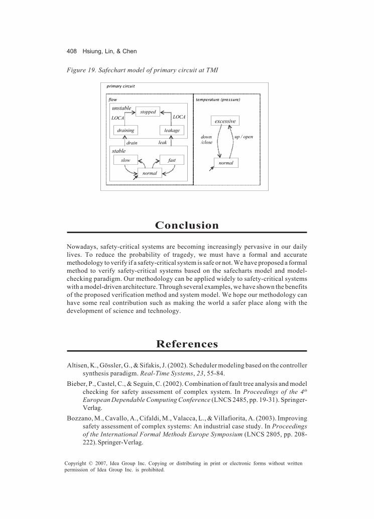
408 Hsiung, Lin, & Chen
Copyright © 2007, Idea Group Inc. Copying or distributing in print or electronic forms without writtenpermission of Idea Group Inc. is prohibited.
Conclusion
Nowadays, safety-critical systems are becoming increasingly pervasive in our dailylives. To reduce the probability of tragedy, we must have a formal and accuratemethodology to verify if a safety-critical system is safe or not. We have proposed a formalmethod to verify safety-critical systems based on the safecharts model and model-checking paradigm. Our methodology can be applied widely to safety-critical systemswith a model-driven architecture. Through several examples, we have shown the benefitsof the proposed verification method and system model. We hope our methodology canhave some real contribution such as making the world a safer place along with thedevelopment of science and technology.
References
Altisen, K., Gössler, G., & Sifakis, J. (2002). Scheduler modeling based on the controllersynthesis paradigm. Real-Time Systems, 23, 55-84.
Bieber, P., Castel, C., & Seguin, C. (2002). Combination of fault tree analysis and modelchecking for safety assessment of complex system. In Proceedings of the 4th
European Dependable Computing Conference (LNCS 2485, pp. 19-31). Springer-Verlag.
Bozzano, M., Cavallo, A., Cifaldi, M., Valacca, L., & Villafiorita, A. (2003). Improvingsafety assessment of complex systems: An industrial case study. In Proceedingsof the International Formal Methods Europe Symposium (LNCS 2805, pp. 208-222). Springer-Verlag.
Figure 19. Safechart model of primary circuit at TMI
����� ��������� �������
normal
stable slow fast
stopped unstable
draining leakage
normal
excessive
up / open down /close
������������
LOCA LOCA
drain leak

Safecharts Model Checking 409
Copyright © 2007, Idea Group Inc. Copying or distributing in print or electronic forms without writtenpermission of Idea Group Inc. is prohibited.
Bozzano, M., & Villafiorita, A. (2003). Improving system reliability via model checking:the FSAP/NuSMV-SA safety analysis platform. In Proceedings of the Interna-tional Conferece on Computer Safety, Reliability and Security (LNCS 2788, pp.49-62). Springer-Verlag.
Clarke, E. M., & Emerson, E. A. (1981). Design and synthesis of synchronizationskeletons using branching time temporal logic. In Proceedings of the Logics ofPrograms Workshop (LNCS 131, pp. 52-71). Springer Verlag.
Clarke, E. M., Grumberg, O., & Peled, D. A. (1999). Model checking. MIT Press.Dammag, H., & Nissanke, N. (1999). Safecharts for specifying and designing safety
critical systems. In Proceedings of the 18th IEEE Symposium on Reliable Distrib-uted Systems (pp. 78-87).
Deneux, J., & Akerlund, O. (2004). A common framework for design and safety analysesusing formal methods. In Proceedings of the International Conference on Proba-bilistic Safety Assurance and Management (PSAM) and European Safety andReliability Conference. Springer.
European Union. (2003). Enhanced Safety Assessment for Complex Systems (ESACS)Project, Retrieved from http://www.esacs.org
Fenelon, P., McDermid, J. A., Nicholson, M., & Pumfrey, D. J. (1994). Towards integratedsafety analysis and design. Applied Computing Review, 2, 21-32.
Henzinger, T. A., Nicollin, X., Sifakis, J., & Yovine, S. (1992). Symbolic model checkingfor real-time systems. In Proceedings of the IEEE International Conference onLogics in Computer Science (pp. 394-406).
Hsiung, P. A., & Lin, S. W. (2005). Model checking timed systems with priorities. InProceedings of the International Conference on Real-Time and Embedded Com-puting Systems and Applications (pp. 539-544). IEEE CS Press.
Hsiung, P. A., & Wang, F. (1998). A state-graph manipulator tool for real-time systemspecification and verification. In Proceedings of the 5th International Conferenceon Real-Time Computing Systems and Applications (pp. 181-188).
Jacky, J. (2000). Formal safety analysis of the control program for a radiation therapymachine. In Proceedings of the 13th International Conference on the Use ofComputers in Radiation Therapy (pp. 68-70). Springer.
Johnson, M. E. (2002). Model checking safety properties of servo-loop control systems.In Proceedings of the International Conference on Dependable Systems andNetworks (pp. 45-50). IEEE CS Press.
Larsen, K. G., Steffen, B., & Weise, C. (1996). Fischer’s protocol revisited: A simple proofusing model constraints. In Hybrid System III (LNCS 1066, pp. 604-615).
Lavazza, L. (Ed.). (2001). A methodology for formalizing concepts underlying the DESSnotation. ITEA.
Leveson, N. G. (1995). Safeware: System safety and computers. Addison Wesley.Leveson, N. G., & Stolzy, J. L. (1987). Safety analysis using Petri nets. IEEE Transactions
on Software Engineering, SE-13(3), 386-397.

410 Hsiung, Lin, & Chen
Copyright © 2007, Idea Group Inc. Copying or distributing in print or electronic forms without writtenpermission of Idea Group Inc. is prohibited.
Lin, S. W., & Hsiung, P. A. (2005). Model checking prioritized timed automata. InProceedings of the International Symposium on Automated Technology forVerification and Analysis (LNCS 3707, pp. 370-384). Springer Verlag.
Nissanke, N., & Dammag, H. (2000a). Risk bands — A novel feature of safecharts. InProceedings of the 11th International Symposium on Software Reliability Engi-neering (pp. 293-301).
Nissanke, N., & Dammag, H. (2000b). Risk ordering of states in safecharts. In Proceedingsof the 19th International Conference on Computer Safety, Reliability, and Secu-rity (LNCS 1943, pp. 395-405). Springer Verlag.
Nissanke, N., & Dammag, H. (2002). Design for safety in safecharts with risk ordering ofstates. Safety Science, 40(9), 753-763.
Queille, J. P., & Sifakis, J. (1982). Specification and verification of concurrent systems inCESAR. In Proceedings of the International Symposium on Programming (LNCS137, pp. 337-351). Springer Verlag.
Sommerville, I. (2004). Software engineering (7th ed.). Addison Wesley.Wang, F., & Hsiung, P. A. (2002). Efficient and user-friendly verification. IEEE Trans-
actions on Computers, 51(1), 61-83.Yang, S. H., Chung, P. W. H., Kowalewski, S., & Stursberg, O. (2000). Automatic safety
analysis of computer controlled plants using model checking. In Proceedings ofthe 10th Symposium on Computer-Aided Process Engineering (ESCAPE 10).
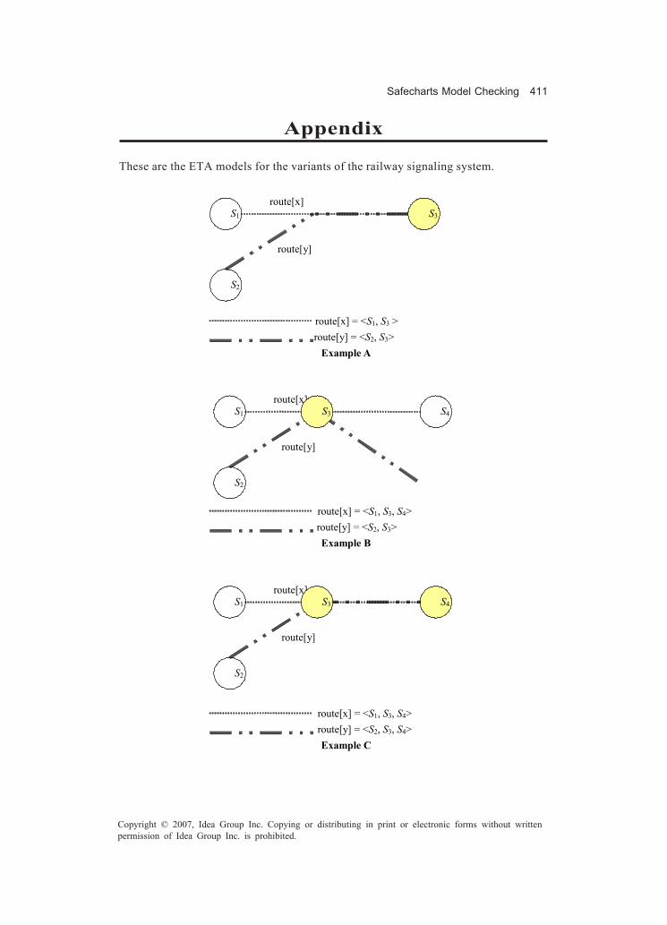
Safecharts Model Checking 411
Copyright © 2007, Idea Group Inc. Copying or distributing in print or electronic forms without writtenpermission of Idea Group Inc. is prohibited.
Appendix
These are the ETA models for the variants of the railway signaling system.
route[x] = <S1, S3 > route[y] = <S2, S3>
Example A
route[x] = <S1, S3, S4> route[y] = <S2, S3>
Example B
route[x] = <S1, S3, S4> route[y] = <S2, S3, S4>
Example C
S4 S1
S2
route[x]
route[y]
S3
S4 S1
S2
route[x]
route[y]
S3
S1
S2
route[x]
route[y]
S3
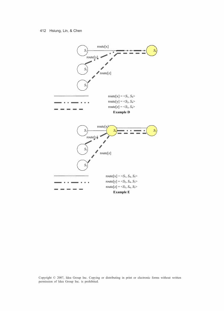
412 Hsiung, Lin, & Chen
Copyright © 2007, Idea Group Inc. Copying or distributing in print or electronic forms without writtenpermission of Idea Group Inc. is prohibited.
route[x] = <S1, S4> route[y] = <S2, S4> route[z] = <S3, S4>
Example D
route[x] = <S1, S4, S5> route[y] = <S2, S4, S5> route[z] = <S3, S4, S5>
Example E
S5 S1
S2
route[x]
route[y]
S4
S3
route[z]
S5 S1
S2
route[x]
route[y]
S4
S3
route[z]

About the Authors 413
Copyright © 2007, Idea Group Inc. Copying or distributing in print or electronic forms without writtenpermission of Idea Group Inc. is prohibited.
About the Authors
Aristides Dasso is an associate professor at the Departmento de Informática atUniversidad Nacional de San Luis, Argentina. He has published more than 50 articles ininternational conferences and journals and has presented several papers in internationalconferences on software engineering and information systems, both areas of researchthat he is currently pursuing, with special emphasis in the area of formal methods. He hasstudied political science in Argentina and computer science in Argentina and France andhas been a fellow at the International Institute for Software Technologies of the UnitedNations University, Macao. He is a member of both ACM and IEEE.
Ana Funes is an assistant professor at the Departamento de Informática at the UniversidadNacional de San Luis, Argentina. She holds a master’s degree in software engineeringfrom that university. She is a researcher at the SEG (Software Engineering Group) of theUniversidad Nacional de San Luis. Her main research interests are focused on formal andsemiformal specification techniques, and testing.
* * * * *
Evon M. O. Abu-Taieh an assistant professor in The Arab Academy for Banking &Financial Sciences, Jordan. She worked for 10 years as IT department head in the Ministryof Transport and has many research papers in simulation, simulation & softwareengineering, GIS, artificial intelligence, and ciphering systems. Her main interests inresearch are: simulation, AI, and ciphering systems. She was posted track chair in IRMAconference in 2006 and track cochair in IRMA Conference 2005. She holds a BSc and MS

414 About the Authors
Copyright © 2007, Idea Group Inc. Copying or distributing in print or electronic forms without writtenpermission of Idea Group Inc. is prohibited.
in computer science from St. Martin’s College and Pacific Lutheran University, respec-tively. She earned her PhD from The Arab Academy for Banking & Financial Sciences.
Hyggo Oliveira de Almeida received an MSc in informatics from the Federal Universityof Campina Grande, in 2004, and a BS in computer science from the Federal Universityof Alagoas, at Maceió, Brazil, in 2002. Currently, he is a PhD student, since 2004, inelectrical engineering at the Federal University of Campina Grande. He has authored orco-authored over 50 research papers, including conferences, journals, and book chap-ters. His research is on the fields of component and multiagent-based dynamic-softwarecomposition, software engineering for embedded systems, and pervasive computing.
Liane Bandeira graduated with a degree in computer science from the State Universityof Ceará – Uece. For a year and a half, she acted as a test analyst, performing activitiesof planning, projection, and execution of software tests, both manual and automated. Shehas also participated in the implantation of functional-system automated tests andcarries on expanding it to other projects. She has participated in the process ofimplementation and certification ISO 9001:2000, defining and formalizing processes andmethodologies of software development based on RUP, ISO, CMM, and CMMI. Before-hand, she was analyst of the Laboratory of Patterns and Quality in Software Engineeringin Uece, where she implanted and audited a development process based on RUP.
Gabriel Baum is co-director of LIFIA (Laboratorio de Investigación y Formación enInformática) at the University of La Plata, Argentina. He is also president of SADIO(Argentinean Society of Computer Science). He is a professor of theoretical computerscience, functional programming and formal languages at the University of La Plata andthe University of Rio Cuarto. He coauthored books and published numerous technicalpapers. His research interests comprise formal methods including specification andderivation of programs, calculus of program construction based on fork algebras andgeneric programs, computability, abstract and concrete complexity, logics, and algebra.
Sami Beydeda studied computer science at the University of Dortmund. After studyingcomputer science, he was a research associate at the Universities of Dortmund andLeipzig (1999-2003). In 2003, he finished his PhD thesis on “The self-testing COTScomponents (STECC) method.” Currently, Beydeda is at the Federal Finance Office(Bundesamt fuer Finance), which is part of the Federal Finance Ministry of Germany.Research interests include testing and analysis, component-based development, model-driven development, and aspect-oriented programming.
David Cabrero is an associate professor at the Department of Computer Science,University of A Coruña, Spain. He received his PhD in Computer Science in 2002(University of A Coruña) for his work on tabular parsing. His research interest includesaccessibility in information systems, distributed programming as well as the use of formalmethods on software engineering, in particular formal verification with theorem proverslike PVS.

About the Authors 415
Copyright © 2007, Idea Group Inc. Copying or distributing in print or electronic forms without writtenpermission of Idea Group Inc. is prohibited.
Yean-Ru Chen received a BS in computer science and information engineering from theNational Chiao Tung University, Hsinchu, Taiwan, ROC in 2002. From 2002 to 2003, shewas employed as an engineer in the SoC Technology Center, Industrial TechnologyResearch Institute, Hsinchu, Taiwan, ROC. She is currently working toward an MS at theNational Chung Cheng University. Her current research interest is formal verification.
Juan José Cuadrado received a BSc in 1994 from Universidad Complutense de Madrid,Spain and a PhD in 2001 from Universidad Carlos III de Madrid, Spain. He lectures at theSchool of Computer Sciences at the University of Alcalá (Spain). His research interestsinclude software measurement and experimentation in software engineering. He is authorof several research papers in scientific journals and books.
Paula Luciana da Cunha is a specialist in e-strategic information management andgraduated in informatics from the University of Fortaleza (UNIFOR). She has worked inthe Instituto Atlântico (software development company, certified in CMM level 2 andISO), for two years as a test analyst. Her main activities are elaboration of institutionalprocedure and processing of software tests; planning of software tests; elaboration andmodeling of test cases; analysis and execution of software tests and test-analysisautomation (with tools Rational Administrator, Rational Test Manager and RationalRobot). She is also a team member of the project Functional Systemic Test Automation,part of the 2005 cycle of the Brazilian Program of Software Quality and Productivity (PBQPSoftware). She also participated in the following trainings: Rational TeamTest Funda-mentals for Performance Testing, Rational TeamTest Fundamentals for FunctionalTesting and CMMi Level 2 – PA of Verification and Validation.
Marcela Daniele has a BS in systems engineering and is currently working on hermaster’s thesis project on software engineering under the supervision of Gabriel Baum.She is a professor and researcher in the Department of Computer Science at the NationalUniversity of Río Cuarto, Argentina. She lectures on system analysis and design andsoftware engineering. Her research interests are software engineering, in particularobject-oriented software modeling. She has published papers involving UML, develop-ment processes, UML extensions, formal methods, and business modelling.
Paula Donegan has been a test analyst at a Brazilian research and developmentinstitution (Instituto Atlântico) for almost 2 years. She has managed test activities, test-case design, and performed manual and automated software tests for various systems.She has experience in automation of software tests using rational test tools (RationalTestStudio). She has an MS in computer science from the State University of Ceará(Uece). She has published papers at national and international events, receiving a prizefrom a renowned Brazilian symposium in 2005. She also presented a project of testautomation for the Brazilian Product Quality Program from the Science and TechnologyMinistry.
416 About the Authors
Copyright © 2007, Idea Group Inc. Copying or distributing in print or electronic forms without writtenpermission of Idea Group Inc. is prohibited.
Anne Eerola teaches software engineering in the Department of Computer Science at theUniversity of Kuopio, Finland. Her research emphasizes requirements management andarchitectures, software modelling and design, and software testing. She has a researchgroup that strives to improve software-engineering methods in healthcare and energydomains.
Luis Fernández received a BSc in 1989 from Universidad Politécnica de Madrid (Spain)and a PhD from Universidad del Pais Vasco in 1997 (his thesis won the extraordinaryaward for doctoral students). He worked as a lecturer at Universidad Politécnica deMadrid for 8 years. He is with the Universidad Europea de Madrid (Spain) as a professorand head of the Department of Computer Systems. His research interests includesoftware quality, testing and software development processes and methodologies. Heis author of research papers in scientific journals and books.
Glauber Ferreira is an MSc student at the Federal University of Campina Grande. Hereceived a BS in computer science from the Federal University of Alagoas, Maceió, Brazil(2004). His research areas include multiagent-systems interaction protocols, pervasivecomputing, and software components for building mobile virtual communities applica-tions.
Elizabeth Furtado is a doctor in computer science and a professor at the University ofFortaleza -UNIFOR in the computer science undergraduate course and in the master’sprogram. She is a consultant in the improvement of software-development processes andin usability of software products. She is part of the national and international programcommittees in the area of human-computer interaction (HCI) and she is the chair of theACM BR-CHI organizing committee. Her most relevant and recent publications are in aworkshop in ICSE 2005, in the Latin-American Conference in HCI (CLIHC 2005) and in theworkshop Task Model and Diagrams for User Interface Design (TAMODIA 2005)concerning the areas of semiotic engineering, software engineering, and usabilityengineering.
Víctor M. Gulías is an associate professor at the Department of Computer Science,University of A Coruña, Spain. He received his PhD in computer science in 2000(University of A Coruña) for his work on distributed functional programming. Hisresearch interest includes functional and object-oriented design and programming aswell as the use of formal methods in the software-development cycle. In the last years,he has been leading the VoDKA project, an industrial-strength distributed video-on-demand server developed using the functional language Erlang.
Pao-Ann Hsiung received a BS degree in mathematics and a PhD degree in electricalengineering from the National Taiwan University (1991 and 1996, respectively). FromFebruary 2001 to July 2002, he was an assistant professor in the Department of ComputerScience and Information Engineering, National Chung Cheng University, where he is

About the Authors 417
Copyright © 2007, Idea Group Inc. Copying or distributing in print or electronic forms without writtenpermission of Idea Group Inc. is prohibited.
currently an associate professor. He was the recipient of the 2001 ACM Kuo-Ting LiYoung Researcher Award and a recipient of the 2004 Young Scholar Research Awardgiven by National Chung Cheng University. He is a member of the IEEE, ACM, and IICM.He has published more than 100 papers in international journals and conferences. Hismain research interests include: formal verification, system-on-chip and embedded-system design and verification, hardware-software co-design, and software engineering.
J. Santiago Jorge is an assistant professor at the Department of Computer Science at theUniversity of A Coruña, Spain. He received his PhD in computer science in 2004 from theUniversity of A Coruña for his work on software verification. His research interestsinclude functional and object-oriented programming, and formal methods of softwareengineering, in particular formal verification with theorem provers.
Pedro J. Lara received a BSc in 1995 from Universidad Politécnica de Madrid, Spain. Hehas been software developer during four years and worked as a Web services andmiddleware consultant in HP Spain for the next two years. Since 2000, he is with the HighTechnical School at Universidad Europea de Madrid (Spain) as lecturer. He is nowdeveloping his PhD thesis at Universidad de Alcalá (Spain). His research interestsinclude software processes, test automation and object-oriented modelling. He is authorof several research papers about these topics.
Yen-Hung Lin received a BS in computer science and information engineering from theNational Chung Cheng University, Chiayi, Taiwan, ROC (2005). He is currently workingtoward an MS at the National Chiao Tung University. His current research interestsinclude VLSI CAD, safety-critical systems, and formal verification.
Pablo E. Martínez López (better known in the academy as Fidel) earned a doctorate ofcomputer science from the National University of Buenos Aires (UBA), Argentina,Magister on Informatics from Pedeciba, University of the Republic, Montevideo, Uru-guay, and Licenciate on Informatics from the National University of La Plata (UNLP) andfrom Latin-American Superior School on Informatics (ESLAI) as part of National Univer-sity of Luján (UNLu), both in Argentina. His teaching and working experience coversmore than 13 years. Currently he is working as a teacher and researcher in the NationalUniversity of La Plata (UNLP), at LIFIA, from the Computer Science Faculty. Before, hehas taught at diverse national universities, such as those of Río IV (UNRC), La Matanza(UNLM), Buenos Aires (UBA), and Rosario (UNR), and has been part of several groupsof software development. His main interests in research are functional programming andprogramming-languages theory, specializing in techniques for automatic production ofprograms, domain-specific languages, and systems for the static analysis of programs.
Emerson Loureiro is an MSc student at the Federal University of Campina Grande, Brazil.He received a BS in computer science from the Federal University of Alagoas, Maceió,Brazil (2004). His current research fields are pervasive computing, mainly on middleware

418 About the Authors
Copyright © 2007, Idea Group Inc. Copying or distributing in print or electronic forms without writtenpermission of Idea Group Inc. is prohibited.
development and software engineering for pervasive computing systems, and service-oriented architectures, focused on service composition and provision for pervasivecomputing environments.
Camila Maia is analyst of systems in the Atlantic Institute, which develops products oftechnology with high value added for its customers, in Fortaleza - CE-Brazil. She actsin the area of software testing, including automation of functional-system tests, planningof activities of test and elaboration of statistics over encountered defects. Before this,she worked in some companies as Web developer. In 1999, she formed techniques inindustrial computers in the Centro Federal de Educação Técnológica - CEFET. In 2004,she was graduated in Computation in the Universidade Federal do Ceará - UFC. In 2005,she concluded the specialization in information technologies with emphasis in Webdevelopment, also in the Universidade Federal do Ceará.
Paola Martellotto has a BS in computer science from the National University of RíoCuarto, Argentina. She is an advance student of a master’s in software engineering. Sheis a teaching assistant in the Computer Science Department at the National Universityof Río Cuarto, Argentina. She also is programmer in computer center at the NationalUniversity of Río Cuarto. Her research focus is in system verification and softwareengineering. She has published papers on type theory, functional and imperativeprogramming, UML extensions, and business modelling.
Cristina Matos is an undergraduate in computer science and postgraduate (specialist)in information strategic management from UNIFOR - University of Fortaleza. Working asa test analyst, she has been busy developing planning activities and performing softwaretests, modeling test cases and automation by using rational tools (e.g., rational admin-istrator, rational test manager and rational robot) for almost three years. She is a memberof the support institutional group for the CMM and ISO development and setup processat Instituto Atlântico, participating in the definition of processes and methodologies ofsoftware development based on RUP (rational unified process) and CMM. She is also aconsultant of the MPS.BR model - Brazilian Software Process Improvement.
Pedro Fernandes Ribeiro Neto received an MSc in electrical engineering from the FederalUniversity of Paraíba, Campina Grande, Brazil (2001), and received a BSc in computerscience from State University of Ceará in 1997. Since 1998, he has been an assistantprofessor of software engineering at the State University of Rio Grande do Norte,Mossoró, Brazil. He is currently a PhD student in electrical engineering in FederalUniversity of Campina Grande, Brazil. His research is in the fields of real-time systems,real-time databases, quality of service, formal methods, and colored Petri nets.
Angelo Perkusich received a PhD and MSc in electrical engineering from FederalUniversity of Paraíba, Campina Grande, Brazil (1994 and 1987, respectively), and receivedhis BSc in electrical engineering from the engineering faculty of Barretos in 1982. From1988 to 1990, he was an assistant professor of electronics and systems at the Federal
About the Authors 419
Copyright © 2007, Idea Group Inc. Copying or distributing in print or electronic forms without writtenpermission of Idea Group Inc. is prohibited.
University of Pernambuco. From 1992 to 1993, he was a visiting research professor at theUniversity of Pittsburgh, Pennsylvania. From 1991 to 1994, he was an assistant professorof electrical engineering at the Federal University of Paraíba, Campina Grande, Brazil.Since 1994, he has been an adjunct professor in that department. He is a project leader/consultant at the affiliated Nokia project for the development of embedded systemsapplications for mobile devices.
Maria Lígia Barbosa Perkusich received a PhD in electrical engineering in 2000, an MScin computer science in 1989, and a bachelor’s degree in informatics in 1985, all fromFederal University of Paraíba, Campina Grande, Brazil. From 1994 to 1997, she was anassistant professor of State University of Paraíba. In 2001, she joined the Department ofInformatics and Statistics, Catholic University of Pernambuco, where she is currently anassistant professor. Her main research interest areas are real-time databases and mobiledatabases.
Mario Piattini has an MSc and a PhD in computer science (Politechnical University ofMadrid) and an MSc in psychology (UNED). He is also a certified information systemauditor and a certified information system manager through ISACA (Information SystemAudit and Control Association) as well as a full professor in the Department of ComputerScience at the University of Castilla - La Mancha, Ciudad Real, Spain. Furthermore, heis the author of several books and papers on databases, software engineering, andinformation systems. He leads the ALARCOS research group of the Department ofInformation Systems and Technologies at the University of Castilla - La Mancha, CiudadReal, Spain. His research interests are: software metrics, IS security and audit, softwaremaintenance, and testing.
Macario Polo is an associate professor at the University of Castilla - La Mancha, wherehe got a PhD in computer science. He is a member of the ALARCOS research group, inthe Department of Information Systems and Technologies. His main research areas fallinto the automation of software maintenance tasks, especially reengineering and testing.
Marisa Analía Sánchez received a PhD in computer science from Universidad Nacionaldel Sur in Bahía Blanca, Argentina. She is currently a professor of graduate andpostgraduate courses at Department of Management Sciences at Universidad Nacionaldel Sur. From 1994 to 2004, she had been on the faculty of the Departments of ComputerScience and Electrical Engineering. Her research interests are in software engineering,particularly software testing. She is also interested in business modeling.
Albert Schilling graduated in computer science from the University of Fortaleza -UNIFOR. He is currently a student at the specialization course for information strategicmanagement at UNIFOR and he is also a researcher and UI designer at the Laboratoryof Software Usability and Quality. He has published the results of his works at the labconcerning the application of a test strategy in a project for the Brazilian DigitalTelevision System in international conferences, such as a Workshop on Advances in

420 About the Authors
Copyright © 2007, Idea Group Inc. Copying or distributing in print or electronic forms without writtenpermission of Idea Group Inc. is prohibited.
Model-Based Software Testing at ICSE 2005 and also in Brazilian workshops focused onDigital TV.
Asim Abdel Rahman El Sheikh is a graduate of the London School of Economics &Political Science, University of London. His major areas of interest are simulation andmodeling. He worked as a consultant and teaching professor in many organizations andwas also a researcher in the computer-aided simulation modeling (CASM) research groupin London. Currently he is the dean of information systems & technology faculty in TheArab Academy for Banking & Financial Sciences, Jordan. He also enjoys system analysisand software engineering in addition to simulation and modeling.
Leandro Silva received his BS in computer science from the Federal University ofAlagoas, Maceió, Brazil (2000) and his MSc in electrical engineering from the FederalUniversity of Campina Grande, Campina Grande, Brazil (2002). Currently, he is a PhDstudent in electrical engineering at the Federal University of Campina Grande. Hisresearch is on the fields of formal software verification, model checking, coloured Petrinets, component-based software systems, and embedded systems. Leandro has spenta year at the University of California, Santa Cruz, working as visiting researcher in thetimed interfaces project with Professor Luca de Alfaro.
Kenia Sousa graduated in computer science from the University of Fortaleza (UNIFOR)and is a graduate student in applied computer science at UNIFOR, Brazil. She is vice-chairof the ACM BR-CHI organizing committee. She has been working with human-computerinteraction (HCI), more specifically on processes, methods, and models of UI design andevaluation. Her most relevant publications were in TAMODIA 2002 and 2004, CADUI2002, INTERACT 2003, HCI INTERNATIONAL 2003 and 2005, two workshops (integra-tion of HCI and SE, and A-MOST) in ICSE 2003, 2004, and 2005, and DSVIS 2005. AtUNIFOR, she is currently working on a research project for the definition of the BrazilianDigital Television System, financed by the Brazilian government.
Tanja Toroi (MSc) is a researcher and PhD student at the University of Kuopio, Finland,where she received her master’s degree in 1999. She has worked in different positions,such as assistant, senior assistant, lecturer, and researcher, at the university since 1998.Her main research interests are software-component testing and conformance testing ofopen interfaces. At the moment, she is working in the OpenTE (open integration testingenvironment) research project, which studies interfaces and their conformance tospecifications especially in health information systems.

Index 421
Copyright © 2007, Idea Group Inc. Copying or distributing in print or electronic forms without writtenpermission of Idea Group Inc. is prohibited.
Index
Aabsolute validity interval 99, 100, 107abstract model 221, 255acceptance test 174ACID (see atomicity, consistency,
isolation, and durability) 101activity diagram 358adaptive techniques 175admission control 102AHL net (see algebraic high-level net)
43algebraic high-level (AHL) net 43algebraic type 287, 291alpha testing 174anonymous function 271, 283, 291aperiodic 98-100application
73, 74, 76, 78, 79, 80, 81, 85,222, 241, 260, 271, 274, 277, 283,288, 291, 308
application integration 119architecture 125argument
231, 232, 237, 251, 271, 274, 277,283, 290, 291, 298, 301, 308
arrival pattern 100
artifact 318, 320, 322, 324, 325, 326assertion checking 169ATLM (see automate testing life-cycle
methodology) 93atomicity, consistency, isolation, and
durabiliity (ACID) 101Australian Healthcare Messaging
Laboratory 122automate testing life-cycle methodology
(ATLM) 93automated software testing 73automated testing 74automatic code generation 382automating software test 72automation management 91automation tool 82axiom 229, 230, 274, 283
Bb-reduction 249, 250basis-path testing 166beta-program 73binary search-based test case genera-
tion (BINTEST) 187, 200binder 274, 290black-box testing 170

422 Index
Copyright © 2007, Idea Group Inc. Copying or distributing in print or electronic forms without writtenpermission of Idea Group Inc. is prohibited.
black-boxing 162BMC software 92Boolean 274, 283, 291, 301, 309bottom-up testing 162, 169bound variable 271, 301, 308boundary value analysis 168branch testing 171Brazilian System for the Digital Televi-
sion 48bug 91bug tracking 87business model 318, 329business process 318, 321business use-case model 322business-analysis model 322, 333
Ccapture/playback tool 83CA (see client application) 35cause-effect graphing 162, 172checklist 60client application (CA) 35code-coverage analyzer 86code-instrumentors tools 86coloured Petri nets 25, 31, 113commercial-off-the-shelf (COTS) 191compatibility function 101completeness
281, 283, 286, 291, 315component
185, 186, 187, 191, 192, 193component object model 189component type 189component-based development
186, 187composition 273, 274, 283computation tree logic 40concrete business model 319, 333condition testing 171conditional 274, 283conformance 118, 121, 123conformance clause 121, 125conformance testing
118, 119, 120, 124, 130, 133consistency 101constructor 283, 301
conventional database system 97conventional technique 175Coq
220, 221, 229, 230, 232, 233, 248correctness
274, 283, 286, 291, 308, 315correctness proof 165currification 277, 278, 283
Ddata access type 100data analysis 165data input (see also input domain) 76,
79data-flow testing 171database management systems 97DBM subtraction 400, 401DC (see duration calculus) 6, 8deadline 98, 100, 102, 110, 115debug 162decidability 274, 290, 291defect 76, 83, 85, 86, 87defect (see also bug) 73defect tracking 87delayable evaluation 391derivation
274, 283, 291, 293, 301, 308, 310, 315design/CPN 26, 31, 32desk checking 163digital 61discrete event simulation 154, 157durability 101duration calculus (DC) 6, 8dynamic VV&T technique 162
Eeager evaluation 391EAI (see external authoring interface)
27effects 306, 308EFSM (see extended finite state
machine) 17Enterprise JavaBeans 189, 190entity bean 190environment 274, 283, 291, 308equivalence partitioning 167

Index 423
Copyright © 2007, Idea Group Inc. Copying or distributing in print or electronic forms without writtenpermission of Idea Group Inc. is prohibited.
Erlang 222, 253execution monitoring 162, 167execution profiling 162, 167execution testing 167execution tracing 162, 167expansion 302, 308expression
274, 283, 291, 301, 303, 308, 315expressiveness 269, 274, 298, 301extended finite state machines (EFSM)
17extended timed automaton (ETA) 386extensible 3D graphics (X3D) 28extensible markup language (XML) 28external authoring interface (EAI) 27,
33
Fface validity 163failure mode and effect analysis (FMEA)
355false 274, 299, 301, 308fault injection 4fault-based symbolic testing 4fault-based testing 2, 3, 20fault-tree 7, 13, 20fault/failure analysis 173field testing 162, 170finite state machine (FSM) 21firm deadline 100fix 274, 283, 302, 308fixpoint 271, 283, 302flattening safechart 397formal language 127, 132formal method 221, 253formal specification 317formal specification language 327formal system 274,
285, 291, 306, 315formal verification 379formal VV&T technique 162free variable 271, 274, 283, 301, 310FSM (see finite state machine) 21FSMWeb technique 21function
271, 274, 283, 291, 301, 308
function space 273, 283function type 273functional 274, 283, 291functional configuration audit 163functional language 274, 287, 291functional program 222functional programming 270, 274functional testing 170functional-testing tool 83functionality 72, 73, 75, 77, 86fusion places 103, 104
Ggeneralization 295, 301generic instance 293generic model 317, 324global state 291, 297, 301grammar 274, 305, 308graph modeling 317, 319graph-based testing method 166graphical comparison 162, 173graphical user interface (GUI) 19GUI-testing tool 83, 85
Hhard deadline 99hardware operations test 74Haskell 274, 305, 308hazard analysis 380HCI (see human-computer interaction)
47, 50, 55, 62HCPN (see hierarchical coloured Petri
net) 26Health Level 7 (HL7)
122, 123, 130, 132healthcare 126heuristic evaluation 56hierarchical coloured Petri net (HCPN)
26, 31, 98, 103, 107, 116higher order logic 180hook method 291HTML 20human-computer interaction (HCI) 47,
50, 55, 62
424 Index
Copyright © 2007, Idea Group Inc. Copying or distributing in print or electronic forms without writtenpermission of Idea Group Inc. is prohibited.
Iidentity function 276, 283, 291identity substitution
282, 283, 291, 301if-then-else 271, 299, 301imprecision 101, 102, 103, 110input domain 75, 76input variation 80inspection 342, 368instance 283, 304, 308instance variable 287, 291integrating the healthcare enterprise
(IHE) 122integration 119interface analysis technique 172interface specification 120, 124interface-driven modeling 93internal consistency 101interoperability
118, 119, 121, 126, 128isolation 101isomorphic 302
JJava 281, 283Java 3D 28, 42Java language 27JavaScript 38JavaScript language 27judgement
274, 283, 285, 290, 291, 315
Kkey word 126
Llack of information
186, 187, 194, 195, 212lambda calculus 173lazy evaluation 391let 271, 274, 283, 291, 301let-bounded polymorphism 290, 291letrec 272, 274list 273, 315
load, performance, and stress testing86
local definition 274, 275logical consistency 97, 99logical constraint 111loop test 171
Mmandatory enforcement 392manual proof 221manual proving 228manual software testing 73manual test 75mapping 102, 112, 278, 291Markov model 355mean time to failure (MTTF) 5memory-leak detection tools 85message sequence chart (MSC) 105,
108, 114message-driven bean 190metacommunication 50metamorphic testing 4metrics 367metrics reporting tool 86minimal cut set (MCS) 381mode predicate 386model checking
32, 40, 221, 379, 380, 388model reduction (see slicing) 13model testing 156model validation 155model verification 156monitoring 102, 112monomorphic 290, 291, 308monotype 290, 291, 308most general unifier 282, 283most important data (MID) 354most important environment (MIE) 354most important no analytical test (MIN)
354most important path (MIP) 354most important test (MIT) 354MSC (see message sequence chart)
105, 108, 114MTTF (see mean time to failure) 5mutation operator 140, 141, 150

Index 425
Copyright © 2007, Idea Group Inc. Copying or distributing in print or electronic forms without writtenpermission of Idea Group Inc. is prohibited.
mutation testing 3mutual exclusion 395
NNational Institute of Standards and
Technology 122natural language 128negotiation 102, 111, 112network-testing tools 86new variable 285, 291non-computable 274notation 290, 291
Oobject oriented 291, 352, 357object-oriented simulation 174Object-Z 317observation 60occurrence graph 107OpenTE project
118, 119, 120, 132, 133oracle 4, 20overloaded type 270, 274overloading 274, 301, 308
Ppaper sketch 63parametric polymorphism
286, 291, 308parse tree (see also syntax tree) 10parser 269, 274partial evaluation 315path analysis 162path testing 171performance metric 102, 112performance test 77periodic 98, 114, 115periodicity 115Petri net 26, 43, 103Petri net kernel (PNK) 42Petri net model 43physical configuration audit 163polymorphic type system
274, 291, 301, 308polymorphism 283, 291, 308
predicate 308predictive validation 162principal type 308process integration 119program 72, 73, 74, 77, 78, 79, 80program slicing 9prohibition 392projection 274, 301proof obligation 231, 241, 242propagation, infection, and execution
(PIE) 5PVS 220, 222, 255, 260, 264
QQoS management 112QoS parameters 102qualified type 296, 301, 308quantification 291quantified variable 291, 301questionnaires 60
Rradiotherapy 127real-time database
96, 97, 98, 99, 100record 301recursion 274, 301, 308, 315recursive call 283, 291recursive definition 274, 308recursive expression 283recursive type 274, 283, 301, 308recursive-descent parsing (see also
parse tree) 10referential transparency 222region 308register 308register allocation 274, 308, 315regression fault 167regression test
73, 74, 76, 77, 81, 92, 162, 167relative validity interval 100RELAY model 4reliability theory 2, 4remote home interface 198remote interface 198renaming 283

426 Index
Copyright © 2007, Idea Group Inc. Copying or distributing in print or electronic forms without writtenpermission of Idea Group Inc. is prohibited.
requirement-driven model-based testautomation 93
requirements 71, 73, 76, 77, 83, 89requirements state machine language
9resource reservation 102retest (see also regression test) 72revealing subdomain 4review 165risk analysis 346, 352risk band 394risk graph 393risk relation 393rule 274, 283, 291, 301, 315, 332
Ssafechart 381, 383, 393safety semantics 391safety-critical system 378, 387scope 274, 301script
74, 75, 77, 78, 79, 80, 82, 85, 87scripting language 87SDCT 122SDP (see software development
process) 48SE (see software engineering) 47security function specification (SFS) 93seed 291, 301self-testability
185, 195, 196, 200, 210semantic-lock technique 101semiformal language 127, 132semiotic engineering 48, 50sensitivity analysis 162, 171sensor network 96, 97, 98, 109session bean 198SFS (see security function specifica-
tion) 93shelfware 83simulation 156, 157, 379simulation model 97simulation-development process 156slicing 9, 10, 12soft deadline 99software component 188
software development 73, 82software development process (SDP)
48software engineering (SE) 47, 49software implementation 50software product 73, 87software quality assurance (SQA) 341software testability 5software testing 119, 120software-development life cycle 107software-engineering practices 155soundness 274specific business model 328specific technique 176specification
102, 108, 112, 221, 274, 283,291, 301, 310, 315
specification-based testing 2, 11specified requirements 80sporadic 99stakeholder 89state graph manipulator (SGM) 380,
389statechart 11, 381, 382statemate semantics 18statement testing 171static analysis 274, 283static type system 274statistical technique 162STECC 185, 192, 200stereotype 325stress test 77, 162, 170structured walkthrough 163submodel testing 162, 172substitution 281, 283, 291substitution transition 103, 104sum type 299, 301, 315sums 301, 308symbolic debugging 162, 172symbolic execution 162symbolic VV&T technique 162syntactic category 274, 283, 291, 301syntax analysis 164syntax directed 291, 301syntax tree (see also parse tree) 10system 88, 89, 90, 91, 92, 93

Index 427
Copyright © 2007, Idea Group Inc. Copying or distributing in print or electronic forms without writtenpermission of Idea Group Inc. is prohibited.
system communicability analysis 50system requirement 318system state graph 387
Ttag 301tagged type 301target architecture 125TCP/IP network 35TD (see timing diagram) 109temporal restriction 97temporal restriction (see also timing
constraint) 97term 274, 283, 291, 301, 308, 315term variable 274, 281, 283test automation 75test case
73, 77, 79, 81, 83, 85, 90, 92, 93,136, 137, 138, 139, 140, 141, 143,144, 145, 147, 150, 151
test class (see also test script, script)73
test engineer 73, 82, 85, 86, 87test environment 346test execution tool 83test procedure (see also test case)
74, 78, 83, 85test scenario 85test script (see also script)
73, 79, 80, 82, 85, 87test stage 72, 82, 83test support tool 83test template 139, 140, 149test-case 136test-case generation 137test-case mutant 140test-case mutation 136test-cases generation algorithm 358test-data extraction tool 85test-data generator 85test-development tool 83test-management tool 86test-procedure generator 83testability
120, 123, 124, 125, 127, 133testable beans approach 211
testing 2, 154, 220, 255, 379testing-completion criteria 346theorem prover 221, 228, 229, 260timed computation tree logic (TCTL)
388timestamp 99, 110timing constraint 99, 105timing diagram (TD) 109top-down testing 162, 169traceability assessment 173transition priority 393, 400transition urgencies 399translation mechanism 328, 329tree 283, 308true 274, 283, 291, 299, 301, 308tuple 274, 290, 291, 296, 298, 301turing test 165type 274, 283, 291, 298, 299, 301,
308, 315type checker 274type equivalence 301type inference
274, 283, 291, 301, 308, 315type language 283, 291, 301type scheme 291type specialization 274, 301, 315type system
274, 283, 291, 301, 308, 315type variable 283, 291, 308type-correctness condition (TCC)
231, 241typechecking 274, 283, 301typing judgement 274, 308, 315
UUI (see user interface) 47UI design alternatives 48UI design patterns 64UI evaluation 51UML (see unified modeling language)
98, 318, 341, 344, 381unification 283, 291unified modeling language (UML)
98, 318, 341, 344, 381unified software development process
318
428 Index
Copyright © 2007, Idea Group Inc. Copying or distributing in print or electronic forms without writtenpermission of Idea Group Inc. is prohibited.
unify 283, 291unit 299, 301unit testing 80, 85universal quantification 291, 304, 308UPi-Test 51, 53, 61usability engineering 48, 50, 55usability inspections method 49usability test 77usability-measurement tool 87use case 72use cases (see also requirements) 76user interface (UI) 47user-interface evaluation 48
Vvalid judgement 283, 315validation 154, 155, 156, 172validation and verification (V&V) 155validation technique 25validity interval 99, 100, 107, 111variable 274, 283, 291, 301variant 274, 301verification 24, 32, 154, 156, 172,
176video-on-demand 222, 253video-on-demand kernel architecture
(VoDKA) 253virtual chat 61virtual reality modeling language 25, 33visualization 162, 170void 287, 301VV&T 162
Wwhite-box testing 162World Wide Web Consortium (W3C)
122
XX3D (see extensible 3D graphics) 28XML (see extensible markup language)
28, 132
Zzone capping 400

InfoSci-OnlineExperience the latest full-text research in the fieldsof Information Science, Technology & Management
infosci-online.comA PRODUCT OF
Publishers of Idea Group Publishing, Information Science Publishing, CyberTech Publishing, and IRM Press
“…The theoretical bentof many of the titlescovered, and the easeof adding chapters toreading lists, makes itparticularly good forinstitutions with stronginformation sciencecurricula.”
— Issues in Science andTechnology Librarianship
To receive your free 30-day trial access subscription contact:Andrew Bundy
Email: [email protected] • Phone: 717/533-8845 x29Web Address: www.infosci-online.com
InfoSci-Online is available to libraries to help keep students,faculty and researchers up-to-date with the latest research inthe ever-growing field of information science, technology, andmanagement.
The InfoSci-Online collection includes:� Scholarly and scientific book chapters � Peer-reviewed journal articles� Comprehensive teaching cases � Conference proceeding papers� All entries have abstracts and citation information � The full text of every entry is downloadable in .pdf format
Some topics covered:� Business Management � Computer Science� Education Technologies� Electronic Commerce � Environmental IS � Healthcare Information Systems� Information Systems � Library Science � Multimedia Information Systems� Public Information Systems � Social Science and Technologies
InfoSci-Onlinefeatures:� Easy-to-use� 6,000+ full-text
entries� Aggregated� Multi-user access

IntroducingIntroducing
The new IGI Teaching Case Collection is a full-text database contain-ing hundreds of teaching cases related to the fields of information science,technology, and management.
Key Features• Project background
information• Searches by keywords and
categories• Abstracts and citation
information• Full-text copies available for
each case• All cases are available in PDF
format with instructor files• Cases are written by IT
educators, researchers, andprofessionals worldwide
The Benefits of the IGI Teaching Case Collection• Frequent updates as new cases are available• Instant access to all full-text articles saves research time• No longer necessary to purchase individual cases• Password-protected case instructor files included in the database
A Product Of
www.igi-online.comFor More Information Visit
www.igi-online.com
IGI Teaching Case Collection
Recommend to your librarian today!
View each case in full-text, PDF form.Hundreds of cases provide a real-worldedge in information technology classes orresearch!