Embed Size (px)
Citation preview
For more information, visit www.desatech.com
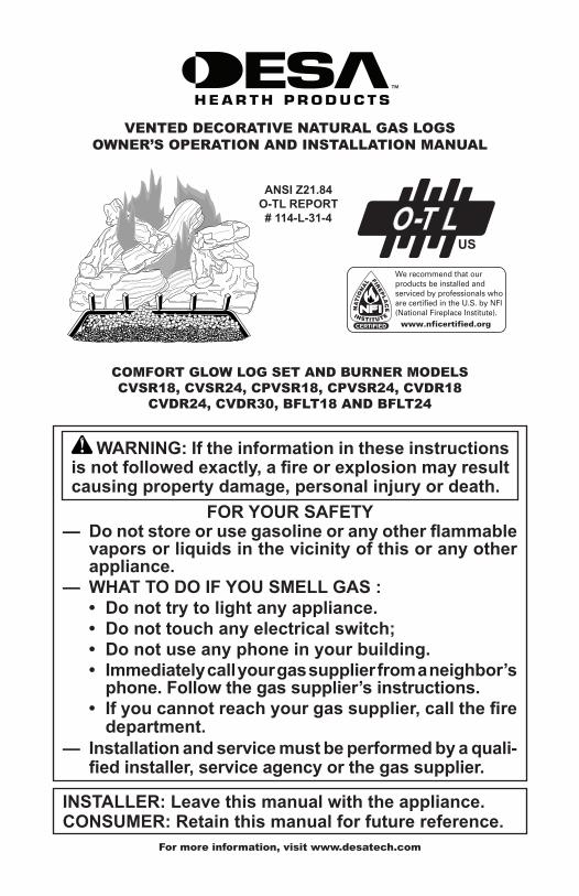
FOR YOUR SAFETY— Donotstoreorusegasolineoranyotherflammable
vapors or liquids in the vicinity of this or any other appliance.
— WHAT TO DO IF YOU SMELL GAS :• Donottrytolightanyappliance.• Donottouchanyelectricalswitch;• Donotuseanyphoneinyourbuilding.• Immediatelycallyourgassupplierfromaneighbor’sphone.Followthegassupplier’sinstructions.
• Ifyoucannotreachyourgassupplier,callthefiredepartment.
— Installationandservicemustbeperformedbyaquali-fiedinstaller,serviceagencyorthegassupplier.
INSTALLER:Leavethismanualwiththeappliance.CONSUMER:Retainthismanualforfuturereference.
WARNING:Iftheinformationintheseinstructionsisnotfollowedexactly,afireorexplosionmayresultcausingpropertydamage,personalinjuryordeath.
VENTED DECORATIVE NATURAL GAS LOGSOWNER’S OPERATION AND INSTALLATION MANUAL
COMFORT GLOW LOG SET AND BURNER MODELS CVSR18, CVSR24, CPVSR18, CPVSR24, CVDR18
CVDR24, CVDR30, BFLT18 AND BFLT24
ANSI Z21.84O-TL REPORT# 114-L-31-4

www.desatech.com 901265-01S2
SAFETy
WARNING:Improperinstal-lation, adjustment, alteration,service or maintenance cancauseinjuryorpropertydamage.Refertothismanualforcorrectinstallation and operational procedures. For assistance or additional information consulta qualified installer, serviceagency or the gas supplier.
WARNING:Thisisagas-firedappliance. It uses air (oxygen)fromtheroominwhichit is in-stalled. Provisions for adequate combustion and ventilation airmust be provided.Refer to theNational Fuel Gas Codes, ANSI Z233.1/NFPA 54, Air for Combus-tion and Ventilation.
WARNING: This appliance is for installation only in a solid-fuel burning masonry orUL127 factory-built fireplace,constructedofnoncombustiblematerial, and connected to aworking flue. (See page 6 forminimumflueopening.)
Thisappliancemaybeinstalledinanaftermarket*,permanentlylocated,manufactured(mobile)home,wherenotprohibitedbystate or local codes.
*Aftermarket:Completionof sale,not forpur-poseofresale,fromthemanufacturer.
State of Massachusetts: The installation must be made bya licensed plumber or gasfitter in theCommonwealth ofMassachusetts.
WARNING: This product con-tainsand/orgenerateschemicalsknowntotheStateofCaliforniatocausecancerorbirthdefectsorotherreproductiveharm.
WARNING:Keepflueopenwhenoperatingunit.
IMPORTANT: Read this owner’smanualcarefullyandcompletelybeforetryingtoassemble,operateorservicethislogset.Improperuseof this log set can cause serious injuryordeath fromburns,fire,explosion, electrical shock andcarbonmonoxidepoisoning.
DANGER:Carbonmonoxidepoisoningmayleadtodeath!
CarbonMonoxidePoisoning: Early signs of carbon monoxide poisoning resemble the flu, with headaches, dizziness or nausea. If you have these signs, the log set may not be working properly. Getfreshairatonce! Have log set serviced. Some people are more affected by carbon monoxide than oth-ers. These include pregnant women, people with heart or lung disease or anemia, those under the influence of alcohol and those at high altitudes.
TABLE OF CONTENTSSafety .................................................................. 2Local Codes......................................................... 4Unpacking............................................................ 4Product Identification ........................................... 5Optional Product Features................................... 5Installation ........................................................... 5Operation ........................................................... 14Cleaning and Maintenance ................................ 15
Troubleshooting ................................................. 16Service Hints ..................................................... 19Technical Service............................................... 19Replacement Parts ............................................ 19Parts .................................................................. 20Accessories ....................................................... 26Warranty ..............................................Back Cover
www.desatech.com901265-01S 3
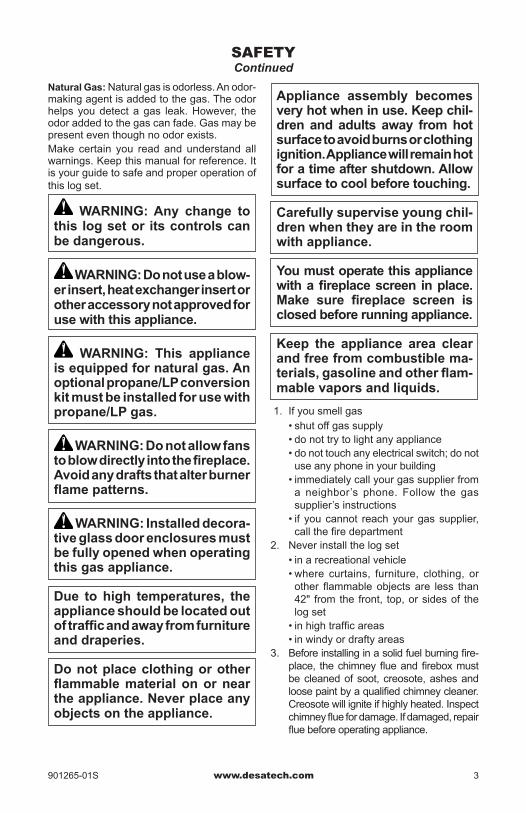
Appliance assembly becomesveryhotwheninuse.Keepchil-drenandadults away fromhotsurfacetoavoidburnsorclothingignition.Appliancewillremainhotforatimeaftershutdown.Allowsurfacetocoolbeforetouching.
Carefully supervise young chil-drenwhentheyareintheroomwithappliance.
Youmustoperatethisappliancewithafireplacescreen inplace.Make sure fireplace screen isclosedbeforerunningappliance.
Keep the appliance area clear andfreefromcombustiblema-terials,gasolineandotherflam-mablevaporsandliquids.
1. If you smell gas• shut off gas supply• do not try to light any appliance• do not touch any electrical switch; do not
use any phone in your building• immediately call your gas supplier from
a neighbor’s phone. Follow the gas supplier’s instructions
• if you cannot reach your gas supplier, call the fire department
2. Never install the log set• in a recreational vehicle• where curtains, furniture, clothing, or
other flammable objects are less than 42" from the front, top, or sides of the log set
• in high traffic areas• in windy or drafty areas
3. Before installing in a solid fuel burning fire-place, the chimney flue and firebox must be cleaned of soot, creosote, ashes and loose paint by a qualified chimney cleaner. Creosote will ignite if highly heated. Inspect chimney flue for damage. If damaged, repair flue before operating appliance.
Natural Gas: Natural gas is odorless. An odor-making agent is added to the gas. The odor helps you detect a gas leak. However, the odor added to the gas can fade. Gas may be present even though no odor exists.Make certain you read and understand all warnings. Keep this manual for reference. It is your guide to safe and proper operation of this log set.
WARNING: Any change to this log set or its controls can bedangerous.
WARNING:Donotuseablow-erinsert,heatexchangerinsertorother accessory not approved for usewiththisappliance.
WARNING: This appliance is equipped for natural gas. An optional propane/LP conversion kitmustbeinstalledforusewithpropane/LP gas.
WARNING:Donotallowfanstoblowdirectlyintothefireplace.Avoidanydraftsthatalterburnerflamepatterns.
WARNING: Installed decora-tiveglassdoorenclosuresmustbefullyopenedwhenoperatingthis gas appliance.
Due to high temperatures, theapplianceshouldbelocatedoutoftrafficandawayfromfurnitureand draperies.
Do not place clothing or other flammablematerialonornearthe appliance. Never place any objectsontheappliance.
SAFETyContinued
www.desatech.com 901265-01S4
4. This log set is designed to be smokeless. If logs ever appear to smoke, turn off appli-ance and call a qualified service person.
Note: During initial operation, slight smok-ing could occur due to log curing and the burning of manufacturing residues. You may wish to add more ventilation by opening a window.
5. To reduce the creation of soot, follow the instructions in Cleaning and Maintenance, page 15.
6. The installation and provisions for combus-tion and ventilation air must conform with the National Fuel Gas Code, ANSI Z233.1/NFPA 54, Air for Combustion and Ventilation.
7. Do not run log set• where flammable liquids or vapors are
used or stored• under dusty conditions
8. Do not burn solid fuel in the fireplace after installing the log set. Do not use this log set to cook food or burn paper or other objects.
SAFETyContinued
9. Do not use appliance if any part has been exposed to or under water. Immediately call a qualified service technician to in-spect the room appliance and to replace any part of the control system (if using GA9050A-1 or GA9150A) and any gas control which has been under water.
10. To help prevent breakage, new logs must be broken-in (see Curing Logs page 14).
11. Turn log set off and let cool before servic-ing, installing, or repairing. Only a qualified service person should install, service, or repair log set.
12. Provide adequate clearances around air openings.
13. This vented gas log set may not be installed in a bedroom or bathroom in the Commonwealth of Massachusetts.
LOCAL CODESInstall and use log set with care. Follow all local codes. In the absence of local codes, use the lat-est edition of The National Fuel Gas Code ANSI Z223.1/NFPA 54*.*Available from:American National Standards Institute, Inc.
1430 BroadwayNew York, NY 10018
National Fire Protection Association, Inc.Batterymarch ParkQuincy, MA 02269
UNPACkING
CAUTION:Donotremovethedataplatesfromtheburnerpan.Thedataplatescontainimpor-tantproductinformation.
1. Remove logs, hearth kit, pan materials, and hardware from carton.
2. Remove all protective packaging applied to logs and base for shipment.
3. Check heater for any shipping damage. If heater is damaged call DESA Heating, LLC at 1-866-672-6040 for replacement parts before returning to dealer.
www.desatech.com901265-01S 5
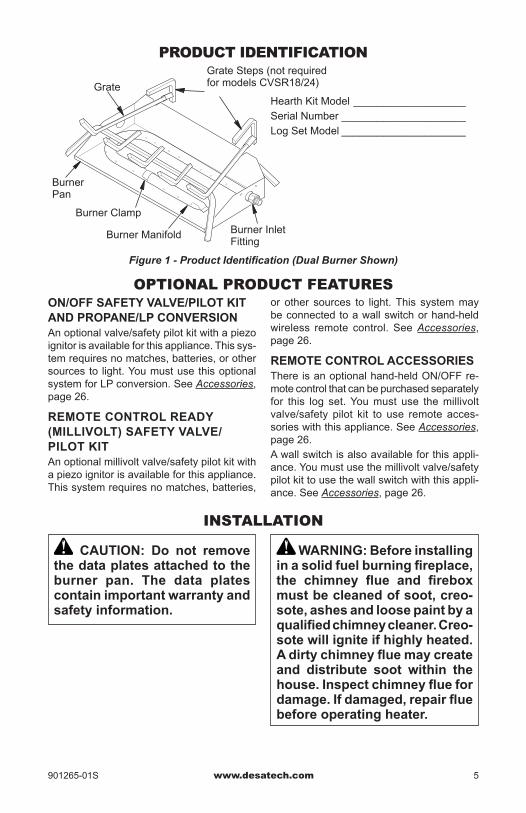
Figure 1 - Product Identification (Dual Burner Shown)
Hearth Kit Model ___________________Serial Number _____________________Log Set Model _____________________
Grate
Burner Pan
Burner Manifold Burner Inlet Fitting
Burner Clamp
Grate Steps (not required for models CVSR18/24)
OPTIONAL PRODUCT FEATURES
PRODUCT IDENTIFICATION
ON/OFF SAFETY VALVE/PILOT KIT AND PROPANE/LP CONVERSIONAn optional valve/safety pilot kit with a piezo ignitor is available for this appliance. This sys-tem requires no matches, batteries, or other sources to light. You must use this optional system for LP conversion. See Accessories, page 26.
REMOTE CONTROL READY (MILLIvOLT)SAFETYvALvE/PILOT KITAn optional millivolt valve/safety pilot kit with a piezo ignitor is available for this appliance. This system requires no matches, batteries,
or other sources to light. This system may be connected to a wall switch or hand-held wireless remote control. See Accessories, page 26.
REMOTE CONTROL ACCESSORIESThere is an optional hand-held ON/OFF re-mote control that can be purchased separately for this log set. You must use the millivolt valve/safety pilot kit to use remote acces-sories with this appliance. See Accessories, page 26.A wall switch is also available for this appli-ance. You must use the millivolt valve/safety pilot kit to use the wall switch with this appli-ance. See Accessories, page 26.
INSTALLATION
CAUTION: Do not removethe data plates attached to the burner pan. The data platescontainimportantwarrantyandsafetyinformation.
WARNING: Before installing inasolidfuelburningfireplace,the chimney flue and fireboxmustbecleanedofsoot,creo-sote,ashesandloosepaintbyaqualifiedchimneycleaner.Creo-sotewilligniteifhighlyheated.Adirtychimneyfluemaycreateand distribute soot within thehouse.Inspectchimneyfluefordamage.Ifdamaged,repairfluebeforeoperatingheater.
www.desatech.com 901265-01S6
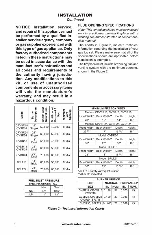
BURNER ORIFICELOG NATURAL PROPANE/LPSIZE IN. NUM. IN. NUM.
CVSR18, CPVSR18CVDR18
0.120 31 0.073 49
CVSR24, CPVSR24CVDR24, BFLT18
0.129 30 0.086 44
CVDR30, BFLT24 0.1405 28 0.089 43
Mo
del
Bu
rner
Des
crip
tio
n
Btu
/Hr
Inp
ut
Nat
ura
l Gas
Btu
/Hr
Inp
ut
Pro
pan
e/L
P
Gas
Minimum
Ven
t O
pen
ing
CPVSR18CVSR18
18"Single 50,000 40,000 8" dia.
CPVSR24CVSR24
24" Single 60,000 50,000 8" dia.
CVDR18 18" Dual 55,000 45,000 8" dia.
CVDR18CVDR24
24" Dual 65,000 55,000 8" dia.
CVDR24 30"Dual 70,000 60,000 8" dia.
BFLT18 18" Triple 65,000 55,000 8" dia.
BFLT24 24" Triple 70,000 60,000 8" dia.
*Add 6" if safety valve/pilot is used **At depth indicated
FUEL INLET PRESSURE SPECIFICATIONS(W.C.)
Min. Max.NG 5.5" 10.5"LP 11" 13"
Figure 2 - Technical Information Charts
MINIMUM FIREBOX SIZES
Models: CPVSR18, CVSR18, CVDR18
Front Width* Back Width** Depth Height
28" 16" 14" 18"
Models: CPVSR24, CVSR24, CVDR24
Front Width* Back Width** Depth Height
29 3/4" 17" 15 1/2" 18"
Model: CVDR30
Front Width* Back Width** Depth Height
36" 27" 18" 18"
Model: BFLT18
Front Width* Back Width** Depth Height
28" 16" 15 1/2" 18"
Model: BFLT24
Front Width* Back Width** Depth Height
30" 22" 15 1/2" 18"
INSTALLATIONContinued
NOTICE: Installation, service,andrepairofthisappliancemustbeperformedbyaqualifiedin-staller,serviceagency,companyorgassupplierexperiencedwiththis type of gas appliance. Only factoryauthorizedcomponentslistedintheseinstructionsmaybeusedinaccordancewiththemanufacturer’sinstructionsandall codes and requirementsofthe authority having jurisdic-tion.Anymodifications to thiskit, or use of unauthorizedcomponentsoraccessoryitemswill void the manufacturer’swarranty, and may result in ahazardous condition.
FLUE OPENING SPECIFICATIONSNote: This vented appliance must be installed only in a solid-fuel burning fireplace with a working flue and constructed of noncombus-tible material.The charts in Figure 2, indicate technical information regarding the installation of your gas log set. Please make sure that all of the specifications shown are applicable before installation is attempted.The fireplace must include a working flue and venting system with the minimum openings shown in the Figure 2.
www.desatech.com901265-01S 7
CHECK GAS TYPEUse only natural gas. If your gas supply is not natural gas, you must install ON/OFF Safety Valve/Pilot Kit (see Accessories, page 26). Call dealer where you bought log set.If the fireplace does not have a gas supply shutoff valve, one must be installed.
VENTING SPECIFICATIONS FOR INSTALLATIONThe fireplace chimney flue and vent must be drafting properly. To check the vent for proper drafting: Light a tightly rolled newspaper on one end and place it at the inside front edge of the fireplace. Observe the smoke and be sure the vent is properly drawing it up the chimney. If the smoke spills out into the room, extinguish the flame and remove any obstruc-tion until proper venting is achieved.The chimney flue must remain open a mini-mum of 3" at all times during the operation of this log set.
For Massachusetts Residents OnlyInstallation of this vented gas log set in the Commonwealth of Massachusetts requires the damper be permanently removed or welded in the fully open position.
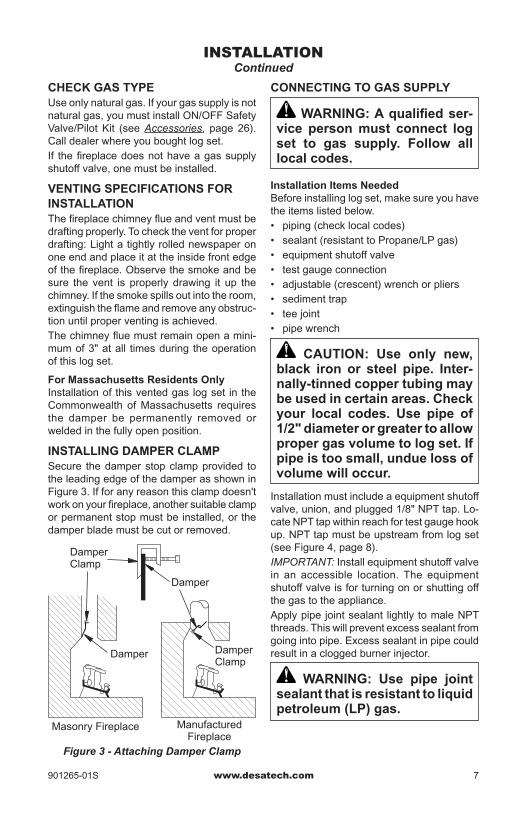
INSTALLING DAMPER CLAMPSecure the damper stop clamp provided to the leading edge of the damper as shown in Figure 3. If for any reason this clamp doesn't work on your fireplace, another suitable clamp or permanent stop must be installed, or the damper blade must be cut or removed.
INSTALLATIONContinued
Damper Clamp
Damper Clamp
Damper
Manufactured Fireplace
Masonry Fireplace
Figure 3 - Attaching Damper Clamp
Damper
CONNECTING TO GAS SUPPLY
WARNING:Aqualifiedser-vice personmust connect logset to gas supply. Follow alllocal codes.
InstallationItemsNeededBefore installing log set, make sure you have the items listed below.• piping (check local codes)• sealant (resistant to Propane/LP gas)• equipment shutoff valve• test gauge connection• adjustable (crescent) wrench or pliers• sediment trap• tee joint• pipe wrench
CAUTION: Use only new,black iron or steel pipe. Inter-nally-tinnedcoppertubingmaybeusedincertainareas.Checkyour local codes. Use pipe of 1/2"diameterorgreatertoallowpropergasvolumetologset.Ifpipeistoosmall,unduelossofvolumewilloccur.
Installation must include a equipment shutoff valve, union, and plugged 1/8" NPT tap. Lo-cate NPT tap within reach for test gauge hook up. NPT tap must be upstream from log set (see Figure 4, page 8).IMPORTANT: Install equipment shutoff valve in an accessible location. The equipment shutoff valve is for turning on or shutting off the gas to the appliance.Apply pipe joint sealant lightly to male NPT threads. This will prevent excess sealant from going into pipe. Excess sealant in pipe could result in a clogged burner injector.
WARNING: Use pipe jointsealant that is resistant to liquid petroleum(LP)gas.
www.desatech.com 901265-01S8
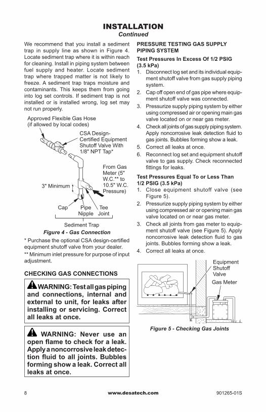
We recommend that you install a sediment trap in supply line as shown in Figure 4. Locate sediment trap where it is within reach for cleaning. Install in piping system between fuel supply and heater. Locate sediment trap where trapped matter is not likely to freeze. A sediment trap traps moisture and contaminants. This keeps them from going into log set controls. If sediment trap is not installed or is installed wrong, log set may not run properly.
INSTALLATIONContinued
Figure 4 - Gas Connection
* Purchase the optional CSA design-certified equipment shutoff valve from your dealer. ** Minimum inlet pressure for purpose of input adjustment.
3" Minimum
Sediment Trap
From Gas Meter (5" W.C.** to 10.5" W.C. Pressure)
CSA Design-Certified Equipment Shutoff Valve With 1/8" NPT Tap*
Approved Flexible Gas Hose (if allowed by local codes)
Tee Joint
Pipe Nipple
Cap
CHECKING GAS CONNECTIONS
WARNING: Test all gas piping and connections, internal andexternaltounit, for leaksafterinstalling or servicing. Correct allleaksatonce.
WARNING: Never use an openflametocheckforaleak.Applyanoncorrosiveleakdetec-tionfluidtoall joints.Bubblesformingshowaleak.Correctallleaksatonce.
PRESSURE TESTING GAS SUPPLY PIPING SYSTEM
TestPressuresInExcessOf1/2PSIG(3.5kPa)1. Disconnect log set and its individual equip-
ment shutoff valve from gas supply piping system.
2. Cap off open end of gas pipe where equip-ment shutoff valve was connected.
3. Pressurize supply piping system by either using compressed air or opening main gas valve located on or near gas meter.
4. Check all joints of gas supply piping system. Apply noncorrosive leak detection fluid to gas joints. Bubbles forming show a leak.
5. Correct all leaks at once.6. Reconnect log set and equipment shutoff
valve to gas supply. Check reconnected fittings for leaks.
Test Pressures Equal To or Less Than 1/2PSIG(3.5kPa)1. Close equipment shutoff valve (see
Figure 5).2. Pressurize supply piping system by either
using compressed air or opening main gas valve located on or near gas meter.
3. Check all joints from gas meter to equip-ment shutoff valve (see Figure 5). Apply noncorrosive leak detection fluid to gas joints. Bubbles forming show a leak.
4. Correct all leaks at once.
Figure 5 - Checking Gas Joints
Gas Meter
Equipment Shutoff Valve
www.desatech.com901265-01S 9
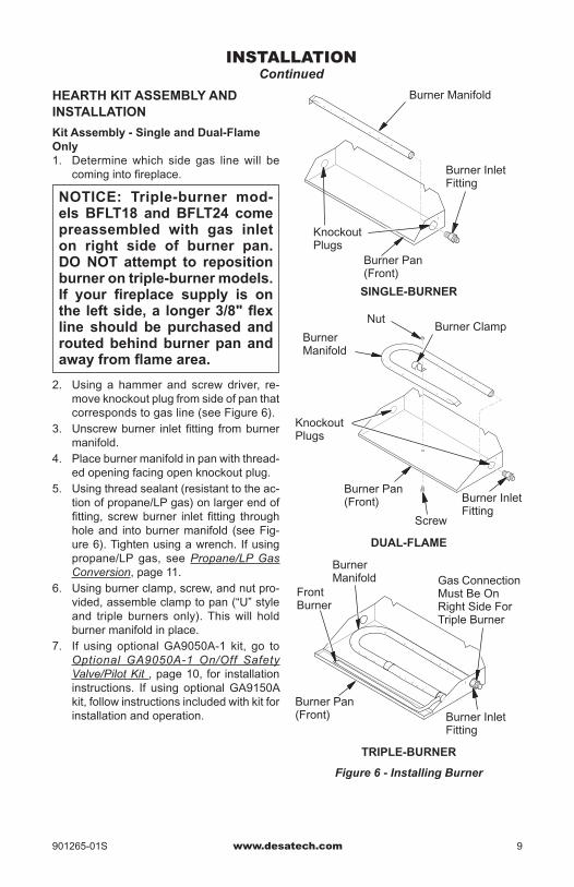
HEARTH KIT ASSEMBLY AND INSTALLATION
KitAssembly-SingleandDual-FlameOnly1. Determine which side gas line will be
coming into fireplace.
NOTICE: Triple-burner mod-els BFLT18 and BFLT24 comepreassembled with gas inleton right side of burner pan.DONOT attempt to repositionburnerontriple-burnermodels.If your fireplace supply is onthe leftside,a longer3/8"flexline should be purchased androutedbehindburnerpanandawayfromflamearea.
2. Using a hammer and screw driver, re-move knockout plug from side of pan that corresponds to gas line (see Figure 6).
3. Unscrew burner inlet fitting from burner manifold.
4. Place burner manifold in pan with thread-ed opening facing open knockout plug.
5. Using thread sealant (resistant to the ac-tion of propane/LP gas) on larger end of fitting, screw burner inlet fitting through hole and into burner manifold (see Fig-ure 6). Tighten using a wrench. If using propane/LP gas, see Propane/LP Gas Conversion, page 11.
6. Using burner clamp, screw, and nut pro-vided, assemble clamp to pan (“U” style and triple burners only). This will hold burner manifold in place.
7. If using optional GA9050A-1 kit, go to Optional GA9050A-1 On/Off Safety Valve/Pilot Kit , page 10, for installation instructions. If using optional GA9150A kit, follow instructions included with kit for installation and operation.
INSTALLATIONContinued
Burner Inlet Fitting
Burner Inlet Fitting
Screw
Front Burner
Burner Manifold
NutBurner Clamp
Burner Pan (Front)
Burner Manifold
Knockout Plugs
Burner Pan(Front)
Burner Pan (Front)
Knockout Plugs
Gas Connection Must Be On Right Side For Triple Burner
Burner Inlet Fitting
TRIPLE-BURNER
SINGLE-BURNER
DUAL-FLAME
Burner Manifold
Figure 6 - Installing Burner

www.desatech.com 901265-01S10
Installation and Gas Connection1. Place burner pan assembly in center of
fireplace floor. Make sure front of pan faces forward.
2. Thread gas supply fitting to fireplace gas supply pipe. Use thread sealant.
3. Install adapter fitting onto burner inlet fit-ting using thread sealant on male threads of burner inlet fitting (see Figure 7). Adjust to most convenient position.
4. Install gas connector tube to gas supply fitting. Carefully shape tube to attach to adapter fitting. Be careful not to cause kinks in tube.
INSTALLATIONContinued
Figure 7 - Connecting Gas to Appliance
Adapter Fitting
Gas Connector Tube
Burner Pan Assembly (Facing Front of Fireplace)
OPTIONAL GA9050A-1 ON/OFF SAFETY VALVE/PILOT KIT ASSEMBLYFor additional convenience and safety, or for propane/LP conversion, an optional ON/OFF safety valve/pilot kit is available. See Acces-sories, page 26.
WARNING:YoumustuseaON/OFFsafetyvalve/pilotkitforpropane/LP conversion.
Natural Gas Installation1. Thread gas control valve onto burner inlet
fitting (see Figure 8). Use thread sealant on male threads of burner inlet fitting. Hold burner inlet fitting with a wrench to prevent overtightening connection to the burner. Make sure control rod is facing the front (see Figure 8).
2. Attach pilot gas line to pilot outlet of gas control valve and tighten. Connect ther-mocouple to rear of gas control valve. See Figure 9. Do not overtighten. If us-ing propane/LP gas, see Changing Pilot Orifice, page 12.
3. Install inlet fitting into inlet opening of gas control valve (see Figure 10). Use thread sealant on male pipe threads.
4. Place burner pan assembly in center of fireplace floor. Make sure front of pan faces forward.
5. Thread gas supply fitting to fireplace gas supply pipe. Adjust to most convenient position.
Burner Inlet Fitting
Gas Control Valve
Burner Pan Assembly
Figure 8 - Installing Gas Control ValveControl Rod
Figure 9 - Gas Control Valve with Thermocouple and Pilot
Figure 10 - Installing Inlet Fitting and Gas Connector Tube
Thermocouple and Line
Pilot and Line
Gas Control Valve
Gas Control Valve
Gas Inlet Fitting
Gas Connector Tube
Inlet Opening
www.desatech.com901265-01S 11
6. Install gas connector tube to gas supply fitting. Carefully shape tube to attach to adapter fitting. Be careful not to cause kinks in tube.
7. Test for leaks following instructions under Testing Burner for Leaks, page 12.
8. Retighten and adjust location of gas control as necessary. Gas control should be level, with control rod to front.
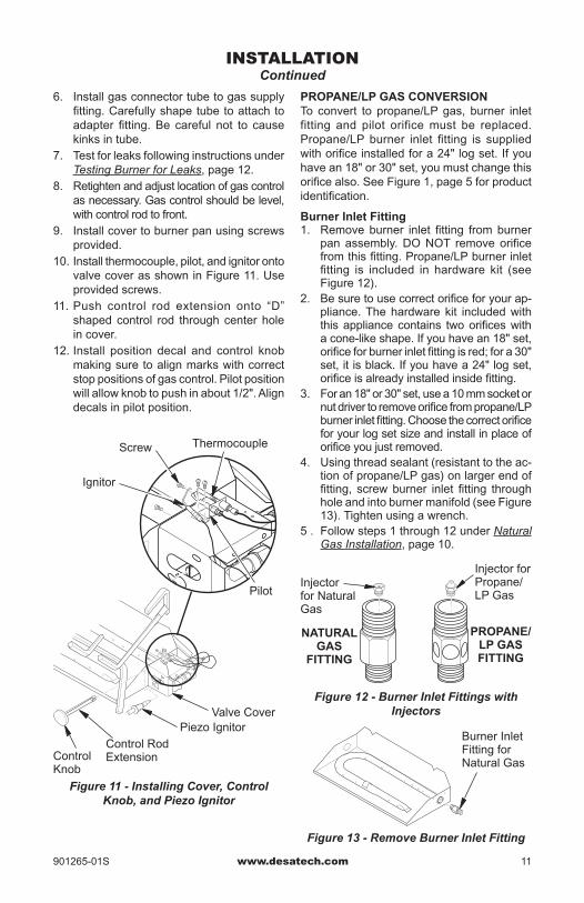
9. Install cover to burner pan using screws provided.
10. Install thermocouple, pilot, and ignitor onto valve cover as shown in Figure 11. Use provided screws.
11. Push control rod extension onto “D” shaped control rod through center hole in cover.
12. Install position decal and control knob making sure to align marks with correct stop positions of gas control. Pilot position will allow knob to push in about 1/2". Align decals in pilot position.
INSTALLATIONContinued
Figure 11 - Installing Cover, Control Knob, and Piezo Ignitor
Piezo Ignitor
Control Rod Extension
Screw
Valve Cover
Control Knob
Thermocouple
Ignitor
Pilot
PROPANE/LP GAS CONVERSIONTo convert to propane/LP gas, burner inlet fitting and pilot orifice must be replaced. Propane/LP burner inlet fitting is supplied with orifice installed for a 24" log set. If you have an 18" or 30" set, you must change this orifice also. See Figure 1, page 5 for product identification.
Burner Inlet Fitting1. Remove burner inlet fitting from burner
pan assembly. DO NOT remove orifice from this fitting. Propane/LP burner inlet fitting is included in hardware kit (see Figure 12).
2. Be sure to use correct orifice for your ap-pliance. The hardware kit included with this appliance contains two orifices with a cone-like shape. If you have an 18" set, orifice for burner inlet fitting is red; for a 30" set, it is black. If you have a 24" log set, orifice is already installed inside fitting.
3. For an 18" or 30" set, use a 10 mm socket or nut driver to remove orifice from propane/LP burner inlet fitting. Choose the correct orifice for your log set size and install in place of orifice you just removed.
4. Using thread sealant (resistant to the ac-tion of propane/LP gas) on larger end of fitting, screw burner inlet fitting through hole and into burner manifold (see Figure 13). Tighten using a wrench.
5 . Follow steps 1 through 12 under Natural Gas Installation, page 10.
Figure 12 - Burner Inlet Fittings with Injectors
Figure 13 - Remove Burner Inlet Fitting
Burner Inlet Fitting for Natural Gas
NATURAL GAS
FITTING
PROPANE/LP GAS FITTING
Injector for Natural Gas
Injector for Propane/LP Gas

www.desatech.com 901265-01S12
ChangingPilotOrificeThe pilot is provided with a natural gas ori-fice installed. For propane/LP gas you must remove it and replace it with an propane/LP orifice. The accessory hardware kit contains an propane/LP orifice with a red stripe for converting pilot.1. Gently loosen and remove pilot line con-
nection from bracket (see Figure 14).2. Replace injector (see Figure 14) with
propane/LP pilot injector with red stripe.3. Replace and tighten pilot line to bracket.4. Continue with step 3 under Natural Gas
Installation, page 10.
INSTALLATIONContinued
Figure 14 - Installing Propane/LP Pilot Orifice
Pilot Injector
TESTING BURNER FOR LEAKS1. Generously apply noncorrosive leak de-
tection fluid to all connections.
WARNING:Nevercheckforgasleakswithopenflame.
2. Light burner with shutoff valve no more than half open and holding a match slightly in front of pan (see Lighting In-structions, page 14).
3. Inspect all connections for bubbles, raw gas odor, or flame from any area other than burner (leaks). If leaks are detected, shut off gas valve immediately. Tighten, or reassemble loose connection(s) using pipe joint compound until burner system is leak free.
4. When burner is tested and leak free, observe individual tongues of flame on burner.
Note: Burner design includes more ports on the outside of the bar. Make sure that all ports are clear and producing flame evenly across burner. If any ports appear blocked, clear them by removing burner manifold and reaming ports with a modi-fied paper clip or other suitable tool.
5. When finished testing, turn gas shutoff valve OFF to extinguish all flames.
ADDING PAN MATERIAL1. Open bag of ash bed material (vermiculite)
and spread it evenly across burner pan to top. You may overflow front and sides of pan to cover entire pan and connecting hardware. Do not cover GA9050A-1 or GA9150A valve.
2. Open glowing embers and evenly cover ash bed material (vermiculite) in burner pan.
INSTALLING GRATE AND LOGS1. Place grate over burner pan where two
outer horizontal supports on grate fit into two pan positioning notches in rear verti-cal edge of pan.
2. Slide two rear log grate steps over two outer horizontal supports on grate as shown in Figure 15. (Not required for models CVSR18/24.)
3. Place back log on grate onto grate steps (see Figure 16, page 13).
4. Place front log(s) on grate and slide forward against front bars on grate (see Figure 16, page 13).
Figure 15 - Installing Grate (Pan Material Not Shown)
GrateGrate Steps
www.desatech.com901265-01S 13
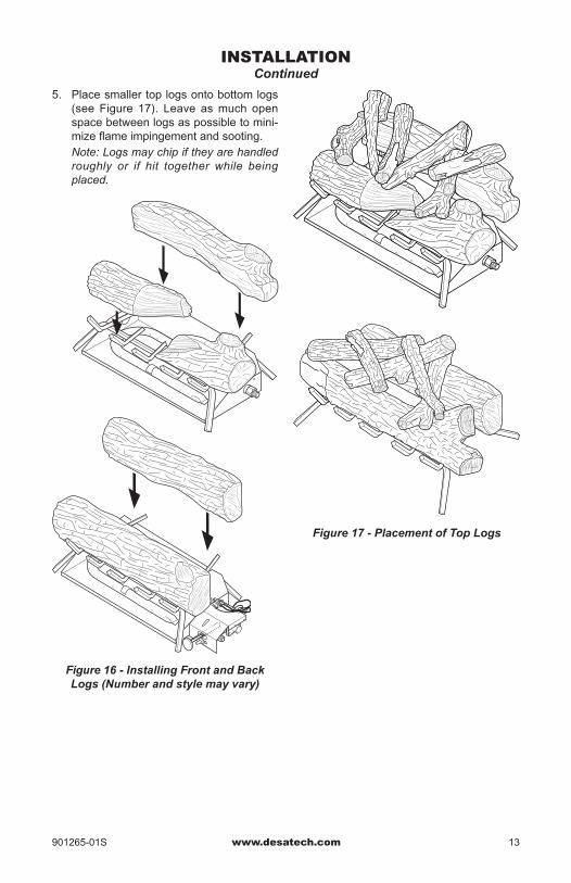
Figure 17 - Placement of Top Logs
INSTALLATIONContinued
Figure 16 - Installing Front and Back Logs (Number and style may vary)
5. Place smaller top logs onto bottom logs (see Figure 17). Leave as much open space between logs as possible to mini-mize flame impingement and sooting.
Note: Logs may chip if they are handled roughly or if hit together while being placed.
www.desatech.com 901265-01S14
GAS SHUTOFFVALVE OPERATION
FlameAdjustmentAdjust the flame ON/OFF by turning gas shut-off valve counterclockwise to open or clockwise to close, as necessary.
Shutting Off ApplianceTurn gas shutoff valve clockwise to OFF position.
CURING LOGS
During the 2-3 hour appliance break-in period, you may detect an odor from the appliance as various paints and compounds used in manufacturing of this log set cure. This is a normal and temporary situation that is not cause for alarm. However, you may want to provide extra ventilation to the room during this time.To ensure proper curing of the logs:• Ignite a 2" flame and maintain it for 1
hour.• Burn logs in consecutive 1 hour periods
raising the flame an additional 2" to full flame height for a total of three hours.
OPERATINGINSTRUCTIONSFOR GA9050A-1
Note: Operation instructions for GA9050A-1 Remote Ready Valve/Pilot Kit will be included with the kit.1. STOP! Read the safety information,
column 1.2. Make sure equipment shutoff valve is fully
open.3. Press in and turn control knob clockwise
to the OFF position.4. Wait five (5) minutes to clear out any gas.
Then smell for gas around log set and near floor. If you smell gas, STOP! Refer to the National Fuel Gas Codes, ANSI Z233.1/NFPA 54, Air for Combustion and Ventilation. If you don’t smell gas, go to the next step.
5. Turn control knob counterclockwise to the PILOT position and press
in. Keep control knob pressed in for five (5) seconds.
OPERATIONFOR YOUR SAFETY
READ BEFORE LIGHTING
WARNING:Keepflueopenwhenoperatingunit.
WARNING: If you do not fol-lowthese instructionsexactly,a fire or explosionmay resultcausingpropertydamage,per-sonalinjuryorlossoflife.
BEFORELIGHTINGsmellallaroundtheap-plianceareaforgas.Besuretosmellnexttothefloorbecausesomegasisheavierthanairandwillsettleonthefloor.WHAT TO DO IF YOU SMELL GAS• Donottrytolightanyappliance.• Donottouchanyelectricswitch;donotuseanyphoneinyourbuilding.
• Immediatelycallyourgassupplierfroma neighbor’s phone. Follow the gassupplier’sinstructions.
• Ifyoucannot reachyourgassupplier,callthefiredepartment.
LIGHTING INSTRUCTIONS
1. STOP! Read the safety information, above.
2. Turn gas shutoff valve to OFF.3. Wait five (5) minutes to clear out any gas.
If you then smell gas STOP! Follow the safety information, above. If you don't smell gas, go on to the next step.
4. Light a match and lay it on top of pan material about 2" from end of supply side of pan
5. Slowly turn gas shutoff valve ON until burner ignites. If burner doesn’t ignite within 10 seconds with match burning, turn shutoff valve OFF and repeat steps 1 through 4 again.
www.desatech.com901265-01S 15
Note: You may be running this log set for the first time after hooking up to gas supply. If so, the control knob may need to be pressed in for 30 seconds. This will allow air to bleed from the gas system.• If control knob does not pop up when
released, contact a qualified service person or gas supplier for repairs.
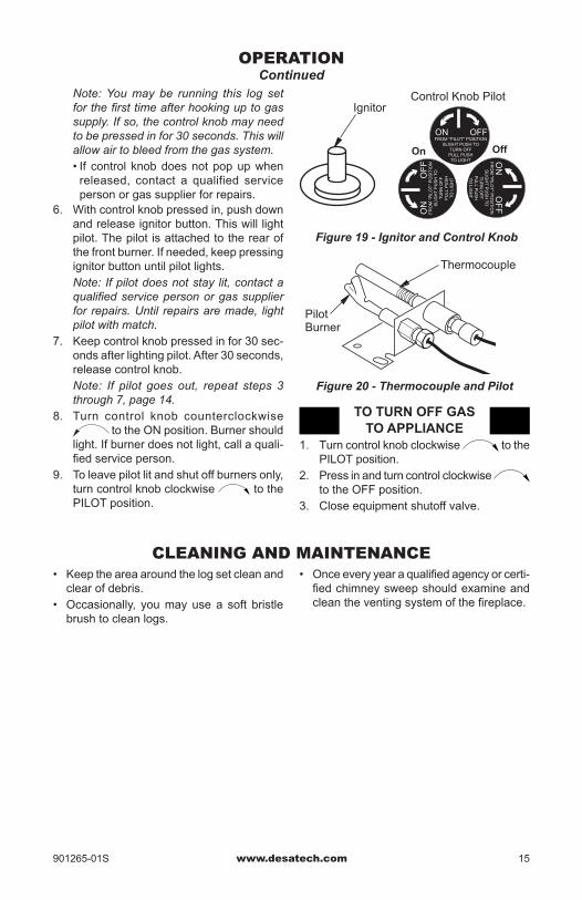
6. With control knob pressed in, push down and release ignitor button. This will light pilot. The pilot is attached to the rear of the front burner. If needed, keep pressing ignitor button until pilot lights.
Note: If pilot does not stay lit, contact a qualified service person or gas supplier for repairs. Until repairs are made, light pilot with match.
7. Keep control knob pressed in for 30 sec-onds after lighting pilot. After 30 seconds, release control knob.
Note: If pilot goes out, repeat steps 3 through 7, page 14.
8. Turn control knob counterclockwise to the ON position. Burner should
light. If burner does not light, call a quali-fied service person.
9. To leave pilot lit and shut off burners only, turn control knob clockwise to the PILOT position.
IgnitorControl Knob Pilot
FROM "PILOT" POSITIONSLIGHT PUSH TO
TURN OFF PULL PUSH TO LIGHT
ON
ON
FR
OM
"PILO
T" P
OS
ITIO
NS
LIGH
T P
US
H T
O
TU
RN
OF
F
PU
LL PU
SH
T
O LIG
HT
FR
OM
"P
ILO
T"
PO
SIT
ION
SLI
GH
T P
US
H T
O
TU
RN
OF
F
PU
LL P
US
H
TO
LIG
HT
ON
OF
F
On Off
OFF
OF
F
Figure 19 - Ignitor and Control Knob
OPERATIONContinued
TO TURN OFF GAS TO APPLIANCE
1. Turn control knob clockwise to the PILOT position.
2. Press in and turn control clockwise to the OFF position.
3. Close equipment shutoff valve.
CLEANING AND MAINTENANCE
Figure 20 - Thermocouple and Pilot
Pilot Burner
Thermocouple
• Keep the area around the log set clean and clear of debris.
• Occasionally, you may use a soft bristle brush to clean logs.
• Once every year a qualified agency or certi-fied chimney sweep should examine and clean the venting system of the fireplace.
www.desatech.com 901265-01S16
TROUBLEShOOTING
WARNING:Turnofflogsetandletcoolbeforeservicing.Onlyaqualifiedservicepersonshouldserviceandrepairlogset.
Note: All troubleshooting items are listed in order of operation.
POSSIBLE CAUSE
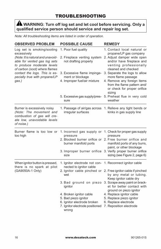
1. Poor fuel quality
2. Fireplace venting system not drafting properly
3. Excessive flame impinge-ment or blockage
4. Improper fuel/air mixture
5. Excessive gas supply/pres-sure
1. Passage of air/gas across irregular surfaces
1. Incorrect gas supply or pressure
2. Blocked burner orifice or burner manifold ports
3. Improper burner orifice size
1. Ignitor electrode not con-nected to ignitor cable
2. Ignitor cable pinched or wet
3. Bad ground on piezo ignitor
4. Broken ignitor cable5. Bad piezo ignitor6. Ignitor electrode broken7. Ignitor electrode positioned
wrong
REMEDY
1. Contact local natural or propane/LP gas company
2. Adjust damper wide open and/or have fireplace and vent ing professional ly cleaned and checked
3. Separate the logs to allow more flame passage
4. Remove any foreign items from the flame pattern and/or check for proper orifice sizing
5. Preheat flue in very cold weather
1. Relieve any tight bends or kinks in gas supply line
1. Check for proper gas supply pressure
2. Free burner orifice and manifold ports of any burrs, paint, or other blockage
3. Verify proper burner orifice sizing (see Figure 2, page 6)
1. Reconnect ignitor cable
2. Free ignitor cable if pinched by any metal or tubing. Keep ignitor cable dry
3. Scrape away paint on brack-et for better contact with ground on piezo ignitor
4. Replace ignitor cable5. Replace piezo ignitor6. Replace electrode7. Reposition electrode
OBSERVED PROBLEM
Log set is smoking/sooting excessively(Note: It is natural and unavoid-able for vented gas log sets to produce moderate levels of carbon (soot) where flames contact the logs. This is es-pecially true with propane/LP gas.)
Burner is excessively noisy(Note: The movement and combustion of gas will cre-ate low, unavoidable levels of noise.)
Burner flame is too low or too high
When ignitor button is pressed, there is no spark at pilot (GA9050A-1 Only)
www.desatech.com901265-01S 17
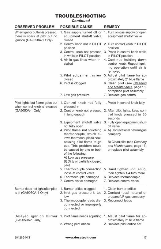
POSSIBLE CAUSE
1. Gas supply turned off or equipment shutoff valve closed
2. Control knob not in PILOT position
3. Control knob not pressed in while in PILOT position
4. Air in gas lines when in-stalled
5. Pilot adjustment screw closed
6. Pilot is clogged
7. Low gas pressure
1. Control knob not fully pressed in
2. Control knob not pressed in long enough
3. Equipment shutoff valve not fully open
4. Pilot flame not touching thermocouple, which al-lows thermocouple to cool, causing pilot flame to go out. This problem could be caused by one or both of the following:
A) Low gas pressure B) Dirty or partially clogged
pilot5. Thermocouple connection
loose at control valve6. Thermocouple damaged7. Control valve damaged
1. Burner orifice clogged2. Inlet gas pressure is too
low3. Thermocouple leads dis-
connected or improperly connected
1. Pilot flame needs adjusting
2. Wrong pilot orifice
REMEDY
1. Turn on gas supply or open equipment shutoff valve
2. Turn control knob to PILOT position
3. Press in control knob while in PILOT position
4. Continue holding down control knob. Repeat ignit-ing operation until air is removed
5. Adjust pilot flame for ap-proximately 2" blue flame
6. Clean pilot (see Cleaning and Maintenance, page 15) or replace pilot assembly
7. Replace gas control
1. Press in control knob fully
2. After pilot lights, keep con-trol knob pressed in 30 seconds
3. Fully open equipment shut-off valve
4. A) Contact local natural gas company
B) Clean pilot (see Cleaning and Maintenance, page 15) or replace pilot assembly
5. Hand tighten until snug, then tighten 1/4 turn more
6. Replace thermocouple7. Replace control valve
1. Clean burner orifice2. Contact local natural or
propane/LP gas company3. Reconnect leads
1. Adjust pilot flame for ap-proximately 2" blue flame
2. Replace pilot orifice set
OBSERVED PROBLEM
When ignitor button is pressed, there is spark at pilot but no ignition (GA9050A-1 Only)
Pilot lights but flame goes out when control knob is released (GA9050A-1 Only)
Burner does not light after pilot is lit (GA9050A-1 Only)
Delayed ignit ion burner (GA9050A-1 Only)
TROUBLEShOOTINGContinued
www.desatech.com 901265-01S18
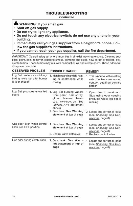
WARNING:Ifyousmellgas• Shutoffgassupply.• Donottrytolightanyappliance.• Donottouchanyelectricalswitch;donotuseanyphoneinyourbuilding.
• Immediatelycallyourgassupplierfromaneighbor’sphone.Fol-lowthegassupplier’sinstructions.
• Ifyoucannotreachyourgassupplier,callthefiredepartment.
IMPORTANT: Operating log set where impurities in air exist may create odors. Cleaning sup-plies, paint, paint remover, cigarette smoke, cements and glues, new carpet or textiles, etc., create fumes. These fumes may mix with combustion air and create odors. These odors will disappear over time.
POSSIBLE CAUSE
1. Metal expanding while heat-ing or contracting while cooling
1. Log Set burning vapors from paint, hair spray, glues, cleaners, chemi-cals, new carpet, etc. (See IMPORTANT statement above)
2. Gas leak. See Warning statementattopofpage
1. Gas leak. See Warning statementattopofpage
2. Control valve defective
1. Gas leak. See Warn-ing statement at topofpage
OBSERVED PROBLEM
Log Set produces a clicking/ticking noise just after burner is lit or shut off
Log Set produces unwanted odors
Gas odor even when control knob is in OFF position
Gas odor during combustion
REMEDY
1. This is normal with most log sets. If noise is excessive, contact qualified service person
1. Open flue to maximum. Stop using odor causing products while log set is running
2. Locate and correct all leaks (see Checking Gas Con-nections, page 8)
1. Locate and correct all leaks (see Checking Gas Con-nections, page 8)
2. Replace control valve
1. Locate and correct all leaks (see Checking Gas Con-nections, page 8)
TROUBLEShOOTINGContinued

www.desatech.com901265-01S 19
SERVICE hINTSWhenGasPressureisTooLow• pilot will not stay lit• burners will have delayed ignition• heater will not produce specified heat• propane/LP gas supply may be lowYou may feel your gas pressure is too low. If so, contact your local propane/LP or natural gas supplier.
TEChNICAL SERVICEYou may have further questions about installa-tion, operation, or troubleshooting. If so, con-tact DESA Heating, LLC at 1-866-672-6040. When calling please have your model and serial numbers of your heater ready.You can also visit DESA Heating, LLC’s web site at www.desatech.com.
REPLACEMENT PARTSNote: Use only original replacement parts. This will protect your warranty coverage for parts replaced under warranty.
PARTS UNDER WARRANTYContact authorized dealers of this product. If they can’t supply original replacement part(s), call DESA Heating, LLC at 1-866-672-6040.When calling DESA Heating, LLC, have ready:• your name• your address• model and serial numbers of your heater• how heater was malfunctioning• purchase date
Usually, we will ask you to return the part to the factory.
PARTS NOT UNDER WARRANTYContact authorized dealers of this product. If they can’t supply original replacement part(s), call DESA Heating, LLC at 1-866-672-6040 for referral information. A list of authorized dealers can be found by visiting www.desatech.com.When calling DESA Heating, LLC, have ready:• model and serial numbers of your heater• the replacement part number

www.desatech.com 901265-01S20
PARTS
MODELSCvSR18,CvSR24,CPvSR18ANDCPvSR24
3
1
8
6
4
2
10
11
12
13
14
15
16
23
17
22 21
20
19
18
75
9
9
Oxford Round Oak Logs
Amherst Round Oak Logs
CPVSR Models Only
www.desatech.com901265-01S 21
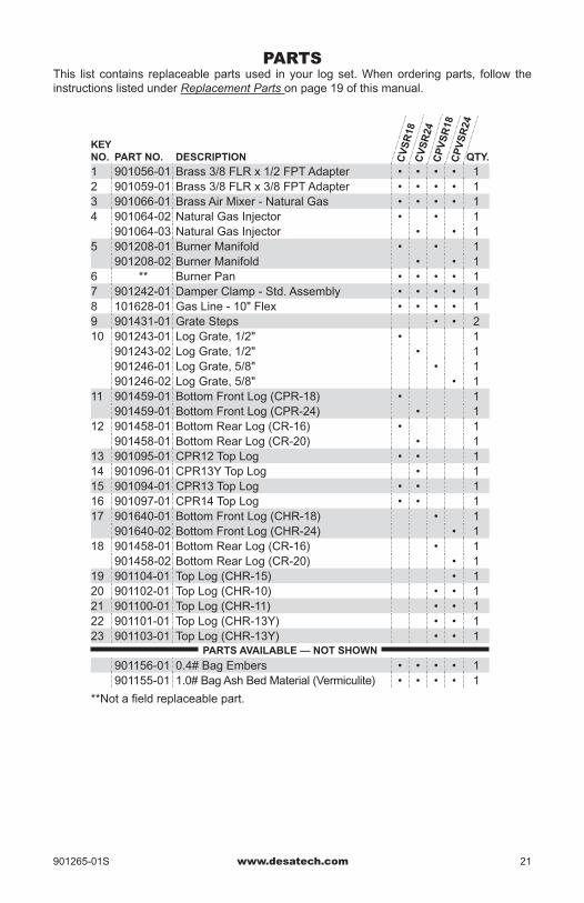
PARTSThis list contains replaceable parts used in your log set. When ordering parts, follow the instructions listed under Replacement Parts on page 19 of this manual.
KEY NO. PART NO. DESCRIPTION QTY.
1 901056-01 Brass 3/8 FLR x 1/2 FPT Adapter • • • • 12 901059-01 Brass 3/8 FLR x 3/8 FPT Adapter • • • • 13 901066-01 Brass Air Mixer - Natural Gas • • • • 14 901064-02 Natural Gas Injector • • 1
901064-03 Natural Gas Injector • • 15 901208-01 Burner Manifold • • 1
901208-02 Burner Manifold • • 16 ** Burner Pan • • • • 17 901242-01 Damper Clamp - Std. Assembly • • • • 18 101628-01 Gas Line - 10" Flex • • • • 19 901431-01 Grate Steps • • 210 901243-01 Log Grate, 1/2" • 1
901243-02 Log Grate, 1/2" • 1901246-01 Log Grate, 5/8" • 1901246-02 Log Grate, 5/8" • 1
11 901459-01 Bottom Front Log (CPR-18) • 1901459-01 Bottom Front Log (CPR-24) • 1
12 901458-01 Bottom Rear Log (CR-16) • 1901458-01 Bottom Rear Log (CR-20) • 1
13 901095-01 CPR12 Top Log • • 114 901096-01 CPR13Y Top Log • 115 901094-01 CPR13 Top Log • • 116 901097-01 CPR14 Top Log • • 117 901640-01 Bottom Front Log (CHR-18) • 1
901640-02 Bottom Front Log (CHR-24) • 118 901458-01 Bottom Rear Log (CR-16) • 1
901458-02 Bottom Rear Log (CR-20) • 119 901104-01 Top Log (CHR-15) • 120 901102-01 Top Log (CHR-10) • • 121 901100-01 Top Log (CHR-11) • • 122 901101-01 Top Log (CHR-13Y) • • 123 901103-01 Top Log (CHR-13Y) • • 1
PARTS AVAILABLE — NOT SHOWN
901156-01 0.4# Bag Embers • • • • 1901155-01 1.0# Bag Ash Bed Material (Vermiculite) • • • • 1
CV
SR
18C
VS
R24
CP
VS
R18
CP
VS
R24
**Not a field replaceable part.
www.desatech.com 901265-01S22
3
13
1
8
6
4
2
10
7
5
9
9
11
12
14a
14a
17c
17b
17d
16a
16b
15b
16b
17f
17e
17a
15d15f
14b
15c
15a
15e
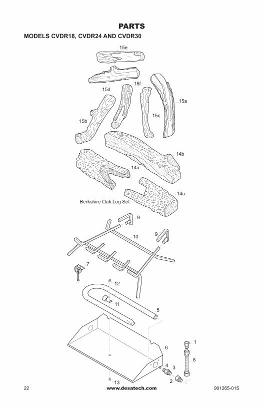
Berkshire Oak Log Set
Coventry Oak Log Set
PARTSMODELS CvDR18,CvDR24ANDCvDR30
www.desatech.com901265-01S 23
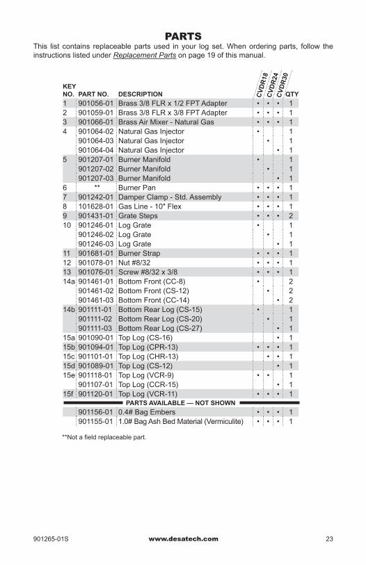
PARTSThis list contains replaceable parts used in your log set. When ordering parts, follow the instructions listed under Replacement Parts on page 19 of this manual.
KEY NO. PART NO. DESCRIPTION QTY
1 901056-01 Brass 3/8 FLR x 1/2 FPT Adapter • • • 12 901059-01 Brass 3/8 FLR x 3/8 FPT Adapter • • • 13 901066-01 Brass Air Mixer - Natural Gas • • • 14 901064-02 Natural Gas Injector • 1
901064-03 Natural Gas Injector • 1901064-04 Natural Gas Injector • 1
5 901207-01 Burner Manifold • 1901207-02 Burner Manifold • 1901207-03 Burner Manifold • 1
6 ** Burner Pan • • • 17 901242-01 Damper Clamp - Std. Assembly • • • 18 101628-01 Gas Line - 10" Flex • • • 19 901431-01 Grate Steps • • • 210 901246-01 Log Grate • 1
901246-02 Log Grate • 1901246-03 Log Grate • 1
11 901681-01 Burner Strap • • • 112 901078-01 Nut #8/32 • • • 113 901076-01 Screw #8/32 x 3/8 • • • 114a 901461-01 Bottom Front (CC-8) • 2
901461-02 Bottom Front (CS-12) • 2901461-03 Bottom Front (CC-14) • 2
14b 901111-01 Bottom Rear Log (CS-15) • 1901111-02 Bottom Rear Log (CS-20) • 1901111-03 Bottom Rear Log (CS-27) • 1
15a 901090-01 Top Log (CS-16) • 115b 901094-01 Top Log (CPR-13) • • • 115c 901101-01 Top Log (CHR-13) • • 115d 901089-01 Top Log (CS-12) • 115e 901118-01 Top Log (VCR-9) • • 1
901107-01 Top Log (CCR-15) • 115f 901120-01 Top Log (VCR-11) • • • 1
PARTS AVAILABLE — NOT SHOWN
901156-01 0.4# Bag Embers • • • 1901155-01 1.0# Bag Ash Bed Material (Vermiculite) • • • 1
**Not a field replaceable part.
CV
DR
18C
VD
R24
CV
DR
30

www.desatech.com 901265-01S24
3
10
1
8
9
4
2
7
15
13
6
5
14
14
22
20
16
17
18
19 21
12
11
Mendocino Oak Log Set
PARTSMODELS BFLT18 AND BFLT24
www.desatech.com901265-01S 25
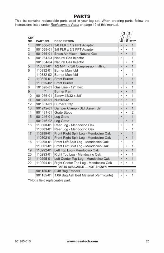
PARTSThis list contains replaceable parts used in your log set. When ordering parts, follow the instructions listed under Replacement Parts on page 19 of this manual.
KEY NO. PART NO. DESCRIPTION QTY.
1 901056-01 3/8 FLR x 1/2 FPT Adapter • • 12 901059-01 3/8 FLR x 3/8 FPT Adapter • • 13 901066-01 Brass Air Mixer - Natural Gas • • 14 901064-03 Natural Gas Injector • 1
901064-04 Natural Gas Injector • 15 110331-01 1/2 MPT x 3/8 Compression Fitting • • 16 110332-01 Burner Manifold • 1
110332-02 Burner Manifold • 17 110325-01 Front Burner • 1
110325-02 Front Burner • 18 101628-01 Gas Line - 12" Flex • • 19 ** Burner Pan • • 110 901076-01 Screw #8/32 x 3/8" • • 111 901078-01 Nut #8/32 • • 112 901681-01 Burner Strap • • 113 901242-01 Damper Clamp - Std. Assembly • • 114 901431-01 Grate Steps • • 215 901246-01 Log Grate • 1
901246-02 Log Grate • 116 110300-01 Rear Log - Mendocino Oak • 1
110303-01 Rear Log - Mendocino Oak • 117 110299-01 Front Right Split Log - Mendocino Oak • 1
110302-01 Front Right Split Log - Mendocino Oak • 118 110298-01 Front Left Split Log - Mendocino Oak • 1
110301-01 Front Left Split Log - Mendocino Oak • 119 110292-01 Left Top Log - Mendocino Oak • • 120 110293-01 Right Top Log - Mendocino Oak • • 121 110295-01 Left Center Top Log - Mendocino Oak • • 122 110294-01 Right Center Top Log - Mendocino Oak • • 1
PARTS AVAILABLE — NOT SHOWN
901156-01 0.4# Bag Embers • • 1901155-01 1.0# Bag Ash Bed Material (Vermiculite) • • 1
BF
LT18
BF
LT24
**Not a field replaceable part.
www.desatech.com 901265-01S26
ACCESSORIES
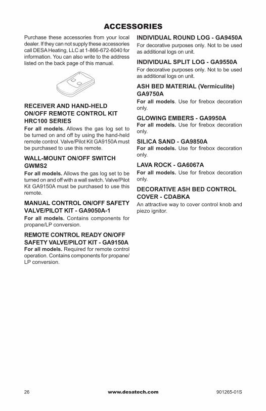
RECEIVER AND HAND-HELD ON/OFF REMOTE CONTROL KIT HRC100 SERIESFor allmodels. Allows the gas log set to be turned on and off by using the hand-held remote control. Valve/Pilot Kit GA9150A must be purchased to use this remote.
WALL-MOUNT ON/OFF SWITCH GWMS2Forallmodels. Allows the gas log set to be turned on and off with a wall switch. Valve/Pilot Kit GA9150A must be purchased to use this remote.
MANUAL CONTROL ON/OFF SAFETY VALVE/PILOT KIT - GA9050A-1For allmodels.Contains components for propane/LP conversion.
REMOTE CONTROL READY ON/OFF SAFETY VALVE/PILOT KIT - GA9150AForallmodels. Required for remote control operation. Contains components for propane/LP conversion.
Purchase these accessories from your local dealer. If they can not supply these accessories call DESA Heating, LLC at 1-866-672-6040 for information. You can also write to the address listed on the back page of this manual.
INDIVIDUAL ROUND LOG - GA9450AFor decorative purposes only. Not to be used as additional logs on unit.
INDIVIDUAL SPLIT LOG - GA9550AFor decorative purposes only. Not to be used as additional logs on unit.
ASH BED MATERIAL (vermiculite)GA9750AForallmodels. Use for firebox decoration only.
GLOWING EMBERS - GA9950AForallmodels. Use for firebox decoration only.
SILICA SAND - GA9850AForallmodels. Use for firebox decoration only.
LAvAROCK-GA6067AForallmodels. Use for firebox decoration only.
DECORATIVE ASH BED CONTROL COVER - CDABKAAn attractive way to cover control knob and piezo ignitor.

www.desatech.com901265-01S 27
NOTES_______________________________________________________________________________________________________________________________________________________________________________________________________________________________________________________________________________________________________________________________________________________________________________________________________________________________________________________________________________________________________________________________________________________________________________________________________________________________________________________________________________________________________________________________________________________________________________________________________________________________________________________________________________________________________________________________________________________________________________________________________________________________________________________________________________________________________________________________________________________________________________________________________________________________________________________________________________________________________________________________________________________________________________________________________________________________________________________________________________________________________________________________________________________________________________________________________________________________________________________________________________________________________________________________________________________________________________________________________________________________________________________________________________________________________________________________________________________________

901265-01Rev. S12/08
901265 01NOT A UPC
DESA Heating, LLC2701 Industrial DriveBowling Green, KY 42101www.desatech.com1-866-672-6040
WARRANTykEEP ThIS WARRANTy
Model (located on product or identification tag) _____________________________
Serial No. (located on product or identification tag) __________________________
Date Purchased __________________________
Keep receipt for warranty verification.
DESA hEATING, LLC LIMITED WARRANTIESNewProducts
Standard Warranty: DESA Heating, LLC warrants this new product and any parts thereof to be free from defects in material and workmanship for a period of one (1) year from the date of first purchase from an authorized dealer provided the product has been installed, maintained and operated in accordance with DESA Heating, LLC’s warnings and instructions.
For products purchased for commercial, industrial or rental usage, this warranty is limited to 90 days from the date of first purchase.
Factory Reconditioned ProductsLimitedWarranty: DESA Heating, LLC warrants factory reconditioned products and any parts thereof to be free from defects in material and workmanship for 30 days from the date of first purchase from an authorized dealer provided the product has been installed, maintained and operated in accordance with DESA Heating, LLC’s warnings and instructions.
TermsCommontoAllWarrantiesThe following terms apply to all of the above warranties:
Always specify model number and serial number when contacting the manufacturer. To make a claim under this warranty the bill of sale or other proof of purchase must be presented.
This warranty is extended only to the original retail purchaser when purchased from an authorized dealer, and only when installed by a qualified installer in accordance with all local codes and instructions furnished with this product.
This warranty covers the cost of part(s) required to restore this product to proper operating condition and an allowance for labor when provided by a DESA Heating, LLC Authorized Service Center or a provider approved by DESA Heating, LLC. Warranty parts must be obtained through authorized dealers of this prod-uct and/or DESA Heating, LLC who will provide original factory replacement parts. Failure to use original factory replacement parts voids this warranty.
Travel, handling, transportation, diagnostic, material, labor and incidental costs associated with warranty repairs, unless expressly covered by this warranty, are not reimbursable under this warranty and are the responsibility of the owner.
Excluded from this warranty are products or parts that fail or become damaged due to misuse, accidents, improper installation, lack of proper maintenance, tampering, or alteration(s).
This is DESA Heating, LLC’s exclusive warranty, and to the full extent allowed by law; this express warranty excludes any and all other warranties, express or implied, written or verbal and limits the duration of any and all implied warranties, including warranties of merchantability and fitness for a particular purpose to one (1) year on new products and 30 days on factory reconditioned products from the date of first purchase. DESA Heating, LLC makes no other warranties regarding this product.
DESA Heating, LLC’s liability is limited to the purchase price of the product, and DESA Heating, LLC shall not be liable for any other damages whatsoever under any circumstances including indirect, incidental, or consequential damages.
Some states do not allow limitations on how long an implied warranty lasts or the exclusion or limitation of incidental or consequential damages, so the above limitation or exclusion may not apply to you.
This warranty gives you specific legal rights, and you may also have other rights which vary from state to state.
For information about this warranty contact: