Embed Size (px)
Citation preview

Save this manual for future reference.
OWNER’S OPERATION AND INSTALLATION MANUAL
VENT-FREE NATURAL GASCOMPACT FIREPLACE
Shown with OptionalCabinet Mantel/Hearth
Base Accessory
®
14,000 to 26,000 Btu/Hrwith Thermostat
CGCF26TNA
This appliance may be installed in an aftermarket* manufactured (mobile) home, where notprohibited by state or local codes.*Aftermarket: Completion of sale, not for purpose of resale, from the manufacturer. (I.E. Installation of this product ispermitted after the manufactured (mobile) home is sited)
WARNING: If the information in this manual is notfollowed exactly, a fire or explosion may result caus-ing property damage, personal injury, or loss of life.
— Do not store or use gasoline or other flammablevapors and liquids in the vicinity of this or anyother appliance.
— WHAT TO DO IF YOU SMELL GAS• Do not try to light any appliance.• Do not touch any electrical switch; do not use
any phone in your building.• Immediately call your gas supplier from a
neighbor’s phone. Follow the gas supplier’sinstructions.
• If you cannot reach your gas supplier, call thefire department.
— Installation and service must be performed by aqualified installer, service agency, or the gassupplier.
WARNING: Improper installa-tion, adjustment, alteration, ser-vice, or maintenance can causeinjury or property damage. Re-fer to this manual for correctinstallation and operationalprocedures. For assistance oradditional information consulta qualified installer, serviceagency, or the gas supplier.
WARNING: This is an unventedgas-fired heater. It uses air(oxygen) from the room inwhich it is installed. Provisionsfor adequate combustion andventilation air must be pro-vided. Refer to Air for Com-bustion and Ventilation sec-tion on page 5 of this manual.
2 104277
VENT-FREE NATURAL GAS COMPACT FIREPLACE
IMPORTANT: Read this owner’smanual carefully and completelybefore trying to assemble, oper-ate, or service this fireplace. Im-proper use of this fireplace cancause serious injury or death fromburns, fire, explosion, electricalshock, and carbon monoxidepoisoning.
SAFETYINFORMATION
Carbon Monoxide Poisoning: Earlysigns of carbon monoxide poisoning re-semble the flu, with headaches, dizziness,or nausea. If you have these signs, the fire-place may not be working properly. Getfresh air at once! Have fireplace serviced.Some people are more affected by carbonmonoxide than others. These include preg-nant women, people with heart or lung dis-ease or anemia, those under the influence ofalcohol, and those at high altitudes.
Natural Gas: Natural gas is odorless. Anodor-making agent is added to natural gas.The odor helps you detect a natural gas leak.However, the odor added to natural gas canfade. Natural gas may be present even thoughno odor exists.
Make certain you read and understand allWarnings. Keep this manual for reference.It is your guide to safe and proper operationof this fireplace.
WARNING ICON G 001
WARNINGS
DANGER: Carbon monoxidepoisoning may lead to death!
WARNING: Any change to thisfireplace or its controls can bedangerous.
1. This appliance is only for use with thetype of gas indicated on the rating plate.This appliance is not convertible for usewith other gases.
2. If you smell gas• shut off gas supply• do not try to light any appliance• do not touch any electrical switch;
do not use any phone in your building.• immediately call your gas supplier
from a neighbor’s phone. Follow thegas supplier’s instructions
• if you cannot reach your gas supplier,call the fire department
3. This fireplace shall not be installed ina bedroom or bathroom.
4. Never install the fireplace• in a recreational vehicle• where curtains, furniture, clothing, or
other flammable objects are less than36 inches from the front, top, or sidesof the fireplace
• as a fireplace insert• in high traffic areas• in windy or drafty areas
5. Do not use this fireplace as a wood-burning fireplace. Use only the logsprovided with the fireplace.
6. Do not add extra logs or ornamentssuch as pine cones, vermiculite, or rockwool. Using these added items cancause sooting. Do not add lava rockaround base. Rock and debris could fallinto the control area of fireplace.
7. You must operate this fireplace with thefireplace screen in place. Make surefireplace screen is in place before run-ning fireplace.
8. This fireplace is designed to be smoke-less. If logs ever appear to smoke, turnoff fireplace and call a qualified ser-vice person. Note: During initial op-eration, slight smoking could occur dueto log curing and fireplace burningmanufacturing residues.
9. To prevent the creation of soot, followthe instructions in Cleaning and Main-tenance, page 19.
10. Do not allow fans to blow directly intothe fireplace. Avoid any drafts that al-ter burner flame patterns. Ceiling fanscan create drafts that alter burner flamepatterns. Altered burner patterns cancause sooting.
11. Before using furniture polish, wax, car-pet cleaner, or similar products, turnheater off. If heated, the vapors fromthese products may create a white pow-der residue within burner box or onadjacent walls or furniture.
12. This fireplace needs fresh air ventila-tion to run properly. This fireplace hasan oxygen depletion sensor (ODS) pi-lot light safety system. The ODS shutsdown the fireplace if not enough freshair is available. See Air for Combus-tion and Ventilation, pages 5 through7. If fireplace keeps shutting off, seeTroubleshooting, pages 16 through 18.
13. Do not run fireplace• where flammable liquids or vapors
are used or stored.• under dusty conditions.
14. Do not use this fireplace to cook foodor burn paper or other objects.
15. Never place any objects in the fireplaceor on logs.
16. Fireplace front and screen becomesvery hot when running fireplace. Keepchildren and adults away from hot sur-faces to avoid burns or clothing igni-tion. Fireplace will remain hot for atime after shut-down. Allow surfacesto cool before touching.
17. Carefully supervise young children whenthey are in same room with fireplace.
18. Do not use fireplace if any part has beenunder water. Immediately call a quali-fied service technician to inspect theroom fireplace and to replace any partof the control system and any gas con-trol which has been under water.
19. Turn off and unplug fireplace and letcool before servicing. Only a qualifiedservice person should service and re-pair fireplace.
20. Operating fireplace above elevations of4,500 feet could cause pilot outage.
21. Do not use a blower insert, heat ex-changer insert, or other accessory notapproved for use with this fireplace.
22. Do not operate fireplace if any log isbroken. Do not operate fireplace if alog is chipped (dime-sized or larger).

3104277
OWNER’S MANUAL
PRODUCTIDENTIFICATION
LOCAL CODESInstall and use fireplace with care. Follow alllocal codes. In the absence of local codes, usethe latest edition of The National Fuel GasCode ANS Z223.1, also known as NFPA 54*.
*Available from:
American National Standards Institute, Inc.1430 Broadway
New York, NY 10018
National Fire Protection Association, Inc.Batterymarch ParkQuincy, MA 02269
Figure 1 - Vent-Free Gas Compact Fireplace
UNPACKING1. Remove log box and fireplace from
carton. The hood is not attached.
2. Remove all protective packaging ap-plied to fireplace for shipment.
3. Make sure your fireplace includes onehardware packet.
4. Check fireplace for any shippingdamage. If fireplace is damaged,promptly inform dealer where youbought fireplace.
PRODUCTFEATURESSAFETY PILOTThis fireplace has a pilot with an OxygenDepletion Sensor Shutoff System (ODS).The ODS/pilot is a required feature for vent-free room fireplaces. The ODS/pilot shuts offthe fireplace if there is not enough fresh air.
PIEZO IGNITION SYSTEMThis fireplace has a piezo ignitor. This sys-tem requires no matches, batteries, or othersources to light fireplace.
THERMOSTATIC HEATCONTROLThis fireplace has a thermostat sensing bulband a control valve. The thermostat willautomatically modulate the heat output tomaintain a consistent room temperature.This results in greater fireplace comfort.This can also result in lower gas bills.
Ignitor Button
FireplaceCabinet
Logs
Screen
Control Knob

4 104277
VENT-FREE NATURAL GAS COMPACT FIREPLACE
WARNING: Failure to positionthe parts in accordance with thesediagrams or failure to use onlyparts specifically approved withthis fireplace may result in prop-erty damage or personal injury.
ASSEMBLY
WARNING: Always havebranch support and screen inplace before operating fireplace.This prevents excessive tempera-tures on fireplace surfaces.
ASSEMBLING FIREPLACETools Required:
• Phillips screwdriver
• 5/16" hex wrench
• slotted screwdriver
Installing Log1. Remove back log, branch, and hood from
log box. Discard protective packaging.
2. Remove two shipping screws abovescreen (see Figure 2).
3. Lift screen up and pull out to remove.
4. An optional blower is available. See Ac-cessories, page 22. Install optionalblower now. Follow installation in-structions provided with blower.
5. Gently place back log on burner sup-port (see Figure 2). The log should fitflat against top of burner support. Placetwo #10 one-inch-long screws throughburner support into the log and tighten.Place branches on branch support (seeFigure 2).
6. Reattach screen by placing notches inscreen frame over shoulder screws andpushing down.
Figure 2 - Assembling Fireplace
Back Log
Screen
Branch
BurnerSupport
Screw
BranchSupport
ScreenShippingScrew
Shoulder Screw
Screw
Figure 3 - Assembling Hood
Assembling Hood1. Locate four #10-3/8" black phillips
sheet metal screws from the hardwarepacket.
2. Remove two 13/4" screws from under-neath middle rail (see Figure 3).
3. Slip top of hood between middle rail andtop of firebox wrapper (see Figure 3).
#10-3/8" Screws
Hood
FireboxWrapper
4. Reinstall two 13/4" screws removed instep 2. Make sure screw pass throughhood and middle rail and attach intoupper louver assembly (see Figure 3).
5. Attach four #10-3/8" hood screws asshown in Figure 3.
Middle Rail

5104277
OWNER’S MANUAL
AIR FORCOMBUSTION ANDVENTILATION
Today’s homes are built more energy effi-cient than ever. New materials, increasedinsulation, and new construction methodshelp reduce heat loss in homes. Home ownersweather strip and caulk around windows anddoors to keep the cold air out and the warm airin. During heating months, home ownerswant their homes as airtight as possible.
While it is good to make your home energyefficient, your home needs to breathe. Freshair must enter your home. All fuel-burningappliances need fresh air for proper com-bustion and ventilation.
Exhaust fans, fireplaces, clothes dryers, andfuel burning appliances draw air from thehouse to operate. You must provide ad-equate fresh air for these appliances. Thiswill insure proper venting of vented fuel-burning appliances.
WARNING: This heater shallnot be installed in a confined spaceor unusually tight constructionunless provisions are provided foradequate combustion and ventila-tion air. Read the following instruc-tions to insure proper fresh air forthis and other fuel-burning appli-ances in your home.
PROVIDING ADEQUATEVENTILATIONThe following are excerpts from NationalFuel Gas Code. NFPA 54/ANS Z223.1, Sec-tion 5.3, Air for Combustion and Ventilation.
All spaces in homes fall into one of the threefollowing ventilation classifications:
1. Unusually Tight Construction
2. Unconfined Space
3. Confined Space
The information on pages 5 through 7 willhelp you classify your space and provideadequate ventilation.
Unusually Tight Construction
The air that leaks around doors and win-dows may provide enough fresh air forcombustion and ventilation. However, inbuildings of unusually tight construction,you must provide additional fresh air.
Unusually tight construction is de-fined as construction where:a. walls and ceilings exposed to the
outside atmosphere have a con-tinuous water vapor retarder witha rating of one perm (6 x 10 -11 kgper pa-sec-m 2) or less with open-ings gasketed or sealed and
b. weather stripping has beenadded on openable windows anddoors and
c. caulking or sealants are appliedto areas such as joints aroundwindow and door frames, be-tween sole plates and floors, be-tween wall-ceiling joints, be-tween wall panels, at penetra-tions for plumbing, electrical, andgas lines, and at other openings.
If your home meets all of the threecriteria above, you must provide ad-ditional fresh air. See Ventilation AirFrom Outdoors , page 7 .
If your home does not meet all of thethree criteria above, proceed to Deter-mining Fresh-Air Flow For FireplaceLocation , page 6.
Confined and Unconfined Space
The National Fuel Gas Code (ANS Z223.1,1992 Section 5.3) defines a confined spaceas a space whose volume is less than 50cubic feet per 1,000 Btu per hour (4.8 m3 perkw) of the aggregate input rating of allappliances installed in that space and anunconfining space as a space whose volumeis not less than 50 cubic feet per 1,000 Btuper hour (4.8 m3 per kw) of the aggregateinput rating of all appliances installed in thatspace. Rooms communicating directly withthe space in which the appliances are in-stalled*, through openings not furnishedwith doors, are considered a part of theunconfined space.
This heater shall not be installed in a con-fined space or unusually tight constructionunless provisions are provided for adequatecombustion and ventilation air.
* Adjoining rooms are communicating onlyif there are doorless passageways or ventila-tion grills between them.
Continued
6 104277
VENT-FREE NATURAL GAS COMPACT FIREPLACE
AIR FORCOMBUSTION ANDVENTILATIONContinued
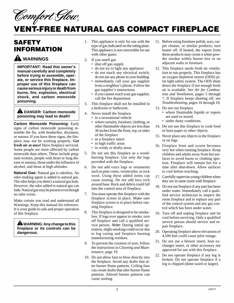
DETERMINING FRESH-AIR FLOW FOR FIREPLACE LOCATION
Determining if You Have a Confined or Unconfined Space
Use this worksheet to determine if you have a confined or unconfined space.
Space : Includes the room in which you will install fireplace plus any adjoining rooms with doorless passageways or ventilation grillsbetween the rooms.
1. Determine the volume of the space (length x width x height).
Length x Width x Height = _________________cu. ft. (volume of space)
Example: Space size 20 ft. (length) x 16 ft. (width) x 8 ft. (ceiling height) = 2560 cu. ft. (volume of space)
If additional ventilation to adjoining room is supplied with grills or openings, add the volume of these rooms to the total volume ofthe space.
2. Divide the space volume by 50 cubic feet to determine the maximum Btu/Hr the space can support.
_________________ (volume of space) ÷ 50 cu. ft. = (Maximum Btu/Hr the space can support)
Example: 2560 cu. ft. (volume of space) ÷ 50 cu. ft. = 51.2 or 51,200 (maximum Btu/Hr the space can support)
3. Add the Btu/Hr of all fuel burning appliances in the space.
Vent-free fireplace _______________ Btu/Hr
Gas water heater _______________ Btu/Hr
Gas furnace _______________ Btu/Hr
Vented gas heater _______________ Btu/Hr
Gas fireplace logs _______________ Btu/Hr
Other gas appliances*+ _______________ Btu/Hr
Total = _______________ Btu/Hr
* Do not include direct-vent gas appliances. Direct-vent draws combustion air from the outdoors and vents to the outdoors.
4. Compare the maximum Btu/Hr the space can support with the actual amount of Btu/Hr used.
_________________ Btu/Hr (maximum the space can support)
_________________ Btu/Hr (actual amount of Btu/Hr used)
Example: 51,200 Btu/Hr (maximum the space can support)
56,000 Btu/Hr (actual amount of Btu/Hr used)
The space in the above example is a confined space because the actual Btu/Hr used is more than the maximum Btu/Hr the space can support.You must provide additional fresh air. Your options are as follows:
A. Rework worksheet, adding the space of an adjoining room. If the extra space provides an unconfined space, remove door to adjoin-ing room or add ventilation grills between rooms. See Ventilation Air From Inside Building, page 7.
B. Vent room directly to the outdoors. See Ventilation Air From Outdoors, page 7.
C. Install a lower Btu/Hr fireplace, if lower Btu/Hr size makes room unconfined.
If the actual Btu/Hr used is less than the maximum Btu/Hr the space can support, the space is an unconfined space. You will need noadditional fresh air ventilation.
WARNING: If the area in which the heater may be operated is smaller than that defined as an unconfined spaceor if the building is of unusually tight construction, provide adequate combustion and ventilation air by one ofthe methods described in the National Fuel Gas Code, ANS Z223.1, 1992, Section 5.3 or applicable local codes.
Example:
Gas water heater 30,000 Btu/Hr
Vent-free fireplace+ 26,000 Btu/Hr
Total = 56,000 Btu/Hr

7104277
OWNER’S MANUAL
Figure 5 - Ventilation Air from Outdoors Shown with Optional Mantel
Ventilation Air From Outdoors
Provide extra fresh air by using ventilationgrills or ducts. You must provide two per-manent openings: one within 12" of theceiling and one within 12" of the floor.Connect these items directly to the outdoorsor spaces open to the outdoors. These spacesinclude attics and crawl spaces.
IMPORTANT: Do not provide openings forinlet or outlet air into attic if attic has athermostat-controlled power vent. Heated airentering the attic will activate the power vent.
OutletAir
VentilatedAttic
OutletAir
InletAir
Inlet Air Ventilated Crawl Space
To CrawlSpace
To Attic
AIR FORCOMBUSTION ANDVENTILATIONContinued
VENTILATION AIR
Ventilation Air From InsideBuilding
This fresh air would come from an adjoiningunconfined space. When ventilating to anadjoining unconfined space, you must pro-vide two permanent openings: one within12" of the ceiling and one within 12" of thefloor on the wall connecting the two spaces(see options 1 and 2, Figure 4). You can alsoremove door into adjoining room (see op-tion 3, Figure 4). Follow the National FuelGas Code NFPA 54/ANS Z223.1, Section5.3, Air for Combustion and Ventilation forrequired size of ventilation grills or ducts.
WARNING: Rework work-sheet, adding the space of theadjoining unconfined space. Thecombined spaces must haveenough fresh air to supply allappliances in both spaces.
Figure 4 - Ventilation Air from Inside Building Shown with Optional Mantel
Or Remove Door into Adjoining
Room, Option 3
Ventilation Grills Into Adjoining Room,
Option 2
12"
12"
VentilationGrills
into AdjoiningRoom,
Option 1

8 104277
VENT-FREE NATURAL GAS COMPACT FIREPLACE
INSTALLATION
WARNING: A qualified ser-vice person must install fireplace.Follow all local codes.
You can recess firebox into the wall. Youcan also position fireplace in the optionalcabinet or corner mantels. IMPORTANT:Only use optional cabinet or corner mantelsspecified in this manual. Purchase the op-tional mantel from your dealer (see Acces-sories, page 22).
CAUTION: This fireplace cre-ates warm air currents. Thesecurrents move heat to wall sur-faces next to fireplace. Installingfireplace next to vinyl or clothwall coverings or operating fire-place where impurities (such astobacco smoke, aromaticcandles, cleaning fluids, oil orkerosene lamps, etc.) in the airexist, may discolor walls.
IMPORTANT: Vent-free fireplaces addmoisture to the air. Although this is benefi-cial, installing fireplace in rooms withoutenough ventilation air may cause mildew toform from too much moisture. See Air forCombustion and Ventilation, pages 5through 7.
LOCATING FIREPLACE
WARNING: Maintain the mini-mum clearances shown in Fig-ures 6 and 7. If you can, providegreater clearances from floor,ceiling, and joining wall.
Note: Your Comfort Glow fireplace is de-signed to be used in zero clearance installa-tions. Wall or framing material can be placeddirectly against any exterior surface on thefireplace, except where stand-off spacersare integrally attached. If stand-off spacersare attached to your fireplace, these spacerscan be placed directly against wall or fram-ing materials.
Use the dimensions shown for rough open-ings to create the easiest installation (seeBuilt-In Fireplace Installation, page 9).
CHECK GAS TYPEUse only natural gas. If your gas supply isnot natural gas, do not install fireplace. Calldealer where you bought fireplace for propertype fireplace.
INSTALLATION ITEMSBefore installing fireplace, make sure youhave the items listed below.
• piping (check local codes)• sealant (resistant to propane/LP gas)• manual shutoff valve *• test gauge connection *• ground joint union• sediment trap• tee joint• pipe wrench
* An A.G.A. design-certified manual shutoffvalve with 1/8" NPT tap is an acceptable
Figure 7 - Mounting Clearances As ViewedFrom Front of Fireplace Shown withOptional Mantel
CAUTION: If you install thefireplace in a home garage• fireplace pilot and burner must
be at least 18 inches abovefloor.
• locate fireplace where movingvehicle will not hit it.
For convenience and efficiency, install fire-place
• where there is easy access for operation,inspection, and service.
• in coldest part of room.
An optional blower kit is available fromyour dealer. See Accessories, page 22. Ifplanning to use blower, locate fireplace nearan electrical outlet.
6"MinimumFromSides OfFireplace
LeftSide
CEILING
36"Minimum
FLOOR
RightSide
Top OfMantel CanBe FlushWith Wall
LeftSide
CEILING
RightSide
36"Minimum
Figure 6 - Mounting Clearances As ViewedFrom Front of Fireplace Shown Built InThe Wall
WARNING: Never install thefireplace• in a bedroom or a bathroom• in a recreational vehicle• where curtains, furniture,
clothing, or other flammableobjects are less than 36 inchesfrom the front, top, or sides ofthe fireplace
• as a fireplace insert• in high traffic areas• in windy or drafty areas
NOTICE: This heater is intendedfor use as supplemental heat. Usethis heater along with your pri-mary heating system. Do not in-stall this heater as your primaryheat source. If you have a centralheating system, you may runsystem’s circulating blower whileusing heater. This will help circu-late the heat throughout thehouse. In the event of a poweroutage, you can use this heateras your primary heat source.
alternative to test gauge connection. Pur-chase the optional A.G.A. design-certifiedmanual shutoff valve from your dealer. SeeAccessories, page 22.
Note: If desired, purchase a four-sided brasstrim kit for built-in installations. See Acces-sories, page 22.

9104277
OWNER’S MANUAL
Continued
Note: A qualified installer should makeall electrical connections.
Figure 10 - Attaching Fireplace to WallStuds
365/8"257/8"
513/4" 267/8"
Figure 9 - Rough Opening for Installing inCorner
2. If installing GA3400(T) blower acces-sory, do so at this time. Follow instruc-tions included with blower accessory.Note: If not installing blower acces-sory, you may wish to run electricalwiring to your fireplace for futureblower installation (see Accessories,page 22). Use only approved three-wireelectrical wiring.
1. Frame in rough opening. Use dimen-sions shown in Figure 8 for the roughopening.
If installing in a corner, use dimensionsshown in Figure 9 for the rough open-ing. The height is 26 7/8" which is thesame as the wall opening above.
267/8"
267/8"
3/4" OffThe FloorMinimum
10 1/2"
Figure 8 - Rough Opening for Installing inWall
BUILT-IN FIREPLACEINSTALLATIONBuilt-in installation of this fireplace involvesinstalling fireplace into a framed-in enclo-sure. This makes the front of fireplace flushwith wall. An optional brass trim kit acces-sory is available (see Accessories, page 22).Brass trim will extend past sides of fireplaceapproximately 1/2 inch. This will cover therough edges of the wall opening. If install-ing a built-in mantel above the fireplace, butyou must follow the clearances shown inFigure 11, page 10. Follow the instructionsbelow to install the fireplace in this manner.Note: Your Comfort Glow fireplace is de-signed to be used in zero clearance installa-tions. Wall or framing material can be placeddirectly against any exterior surface on therear, sides, or top of your fireplace.
Actual Framing
Height 26" 26 7/8"
Front Width 26 3/4" 26 7/8"
Depth 9 1/2" 10 1/2"
Bottom 3/4" 3/4"
INSTALLATIONContinued
Nails orWoodScrews
NailingFlanges
3. Install gas piping to fireplace location.This installation includes an approvedflexible gas line (if allowed by localcodes) after the manual shutoff valve.The flexible gas line must be the lastitem installed on the gas piping.
4. If you have not assembled firebox, fol-low instructions on page 4.
5. Carefully set fireplace in front of roughopening with back of fireplace insidewall opening.
6. Attach flexible gas line to fireplace gasregulator. See Connecting Fireplace toGas Supply, page 12.
7. Bend four nailing flanges on outer cas-ing with pliers (see Figure 10).
8. Attach fireplace to wall studs usingnails or wood screws through holes innailing flange.
9. Check all gas connections for leaks. SeeChecking Gas Connections, page 13.
10. If using optional brass trim kit, installthe trim after final finishing and/orpainting of wall. See instructions in-cluded with brass trim accessory for at-taching brass trim.
WARNING: If pre-wiring, donot connect wiring to any electri-cal source at this time.
Install fireplace electrical outletand connect wiring to outlet be-fore connecting to electricalsource. The fireplace electricaloutlet is included with theGA3450(T) blower accessory.
Only use the fireplace electricaloutlet supplied with theGA3450(T) blower accessory.
10 104277
VENT-FREE NATURAL GAS COMPACT FIREPLACE
13"
16"
19"
21"
2 1/2"
6"
8"
10"Note:All verticalmeasurementsare from top offireplaceopening to bottom ofmantel shelf. Allmeasurementsare in inches.
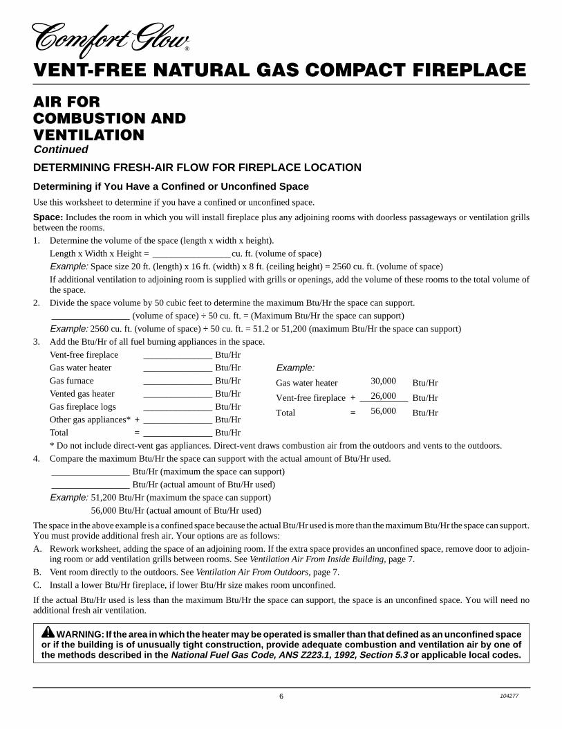
INSTALLATIONContinuedMANTEL CLEARANCES FORBUILT-IN INSTALLATIONIf placing mantel above built-in fireplace,you must meet minimum clearance betweenmantel shelf and top of fireplace opening.
If your installation does not meet the aboveminimum clearances, you must:
• raise the mantel to an acceptable height
OR
• remove the mantel.
Figure 11 - Minimum Mantel Clearancesfor Built-In Installation
Mantel Shelf
Side ofFirebox
Figure 12 - Attaching Brass Trim to Fireplace
OPTIONAL MANTELINSTALLATIONNote: Refer to instructions provided withthe mantel for assembly instructions. Referto instructions below for system installa-tion. Refer to instructions on page 4 forfirebox assembly. Blower accessory shouldbe installed if it is being used (see Accesso-ries, page 22).
1. Unscrew four brass screws that attachtop louver to fireplace. Remove louverfrom fireplace and set aside.
2. Place fireplace on wood base.
3. Place mantel around fireplace/baseassembly.
4. Assemble brass trim kit. See Assem-bling Brass Trim, page 11.
ShoulderScrews
AssembledBrass Trim
Hole for 3"wood screwfor attachingfireplace towooden base
Hole for 3"wood screwforattachingfireplace tomantel
5. Firmly snap brass trim kit on shoulderscrews. Shoulder screws are located onfireplace cabinet (see Figure 12).
6. Align brass trim kit for flush fit aroundopening.
7. Use two 3" wood screws provided andattach fireplace base to wooden base(see Figure 12).
8. Remove brass trim kit and mantel. Becareful not to damage wall or mantel.
9. Place wood base next to wall at instal-lation location.
10. Attach wood base to floor with two1 3/4" black screws provided (see Fig-ure 13). If the floor is concrete use an-chor method (see Attaching Wood Baseto Solid Floor, page 11).
11. Install gas line. See Connecting To GasSupply, page 11.
12. Check for leaks. See Checking GasConnections, page 13.
13. Place mantel around fireplace. Be care-ful not to damage wall or mantel.
14. Place brass trim kit on the shoulderscrews located on the side and top ofthe fireplace. Firmly snap the brass trimover the shoulder screws on fireplace(see Figure 12).
15. Adjust assembly to remove any gaps.Attach remaining two 3" wood screwsfrom hardware pack through openingsinside of fireplace sides into the man-tel. The openings are located at top be-hind the area for the brass louvers (seeFigure 13).
16. Reinstall top brass louvers.
Figure 13 - Attaching Wood Base to Floor
1 3/4" Screw
Wood Base
11104277
OWNER’S MANUAL
CONNECTING TO GASSUPPLY
WARNING: A qualified ser-vice person must connect fire-place to gas supply. Follow alllocal codes.
IMPORTANT: Check gas line pressurebefore connecting fireplace to gas line. Gasline pressure must be no greater than 14inches of water. If gas line pressure is higher,fireplace regulator damage could occur.
Installation must include a manual shutoffvalve, union, and plugged 1/8" NPT tap.Locate NPT tap within reach for test gaugehook up. NPT tap must be upstream fromfireplace (see Figure 16).
Apply pipe joint sealant lightly to malethreads. This will prevent excess sealantfrom going into pipe. Excess sealant in pipecould result in clogged fireplace valves.
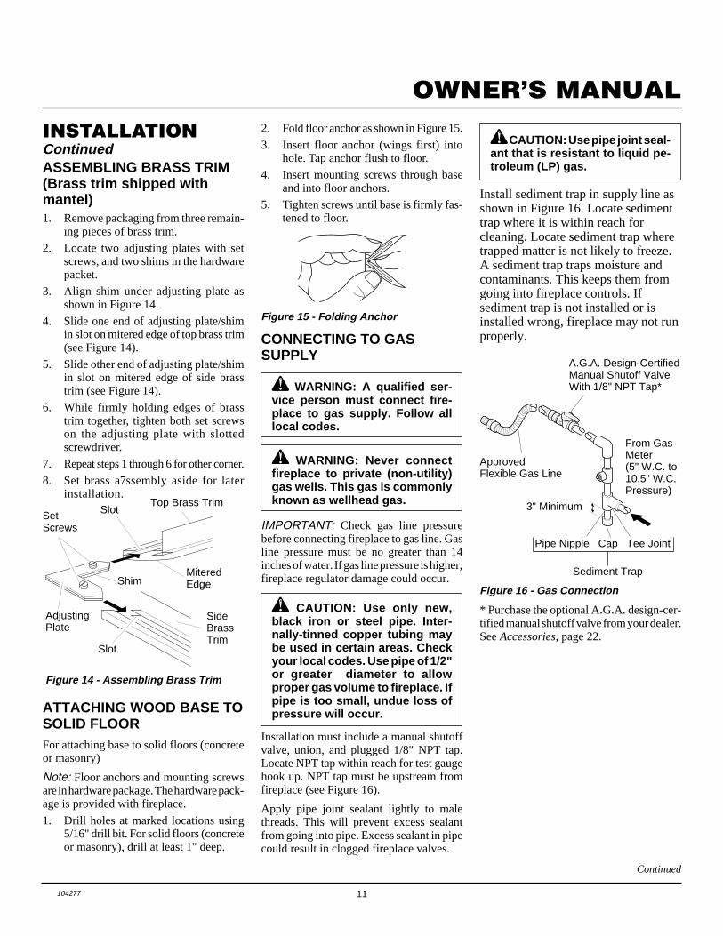
Install sediment trap in supply line asshown in Figure 16. Locate sedimenttrap where it is within reach forcleaning. Locate sediment trap wheretrapped matter is not likely to freeze.A sediment trap traps moisture andcontaminants. This keeps them fromgoing into fireplace controls. Ifsediment trap is not installed or isinstalled wrong, fireplace may not runproperly.
WARNING: Never connectfireplace to private (non-utility)gas wells. This gas is commonlyknown as wellhead gas.
CAUTION: Use only new,black iron or steel pipe. Inter-nally-tinned copper tubing maybe used in certain areas. Checkyour local codes. Use pipe of 1/2"or greater diameter to allowproper gas volume to fireplace. Ifpipe is too small, undue loss ofpressure will occur.
CAUTION: Use pipe joint seal-ant that is resistant to liquid pe-troleum (LP) gas.
* Purchase the optional A.G.A. design-cer-tified manual shutoff valve from your dealer.See Accessories, page 22.
Figure 16 - Gas Connection
ATTACHING WOOD BASE TOSOLID FLOORFor attaching base to solid floors (concreteor masonry)
Note: Floor anchors and mounting screwsare in hardware package. The hardware pack-age is provided with fireplace.
1. Drill holes at marked locations using5/16" drill bit. For solid floors (concreteor masonry), drill at least 1" deep.
Figure 15 - Folding Anchor
ASSEMBLING BRASS TRIM(Brass trim shipped withmantel)1. Remove packaging from three remain-
ing pieces of brass trim.
2. Locate two adjusting plates with setscrews, and two shims in the hardwarepacket.
3. Align shim under adjusting plate asshown in Figure 14.
4. Slide one end of adjusting plate/shimin slot on mitered edge of top brass trim(see Figure 14).
5. Slide other end of adjusting plate/shimin slot on mitered edge of side brasstrim (see Figure 14).
6. While firmly holding edges of brasstrim together, tighten both set screwson the adjusting plate with slottedscrewdriver.
7. Repeat steps 1 through 6 for other corner.
8. Set brass a7ssembly aside for laterinstallation.
Figure 14 - Assembling Brass Trim
INSTALLATIONContinued
Top Brass Trim
SideBrassTrim
MiteredEdgeShim
SetScrews
AdjustingPlate
Slot
Slot
A.G.A. Design-CertifiedManual Shutoff ValveWith 1/8" NPT Tap*
3" Minimum
From GasMeter(5" W.C. to10.5" W.C.Pressure)
ApprovedFlexible Gas Line
Pipe Nipple Cap Tee Joint
Sediment Trap
2. Fold floor anchor as shown in Figure 15.
3. Insert floor anchor (wings first) intohole. Tap anchor flush to floor.
4. Insert mounting screws through baseand into floor anchors.
5. Tighten screws until base is firmly fas-tened to floor.
Continued
12 104277
VENT-FREE NATURAL GAS COMPACT FIREPLACE
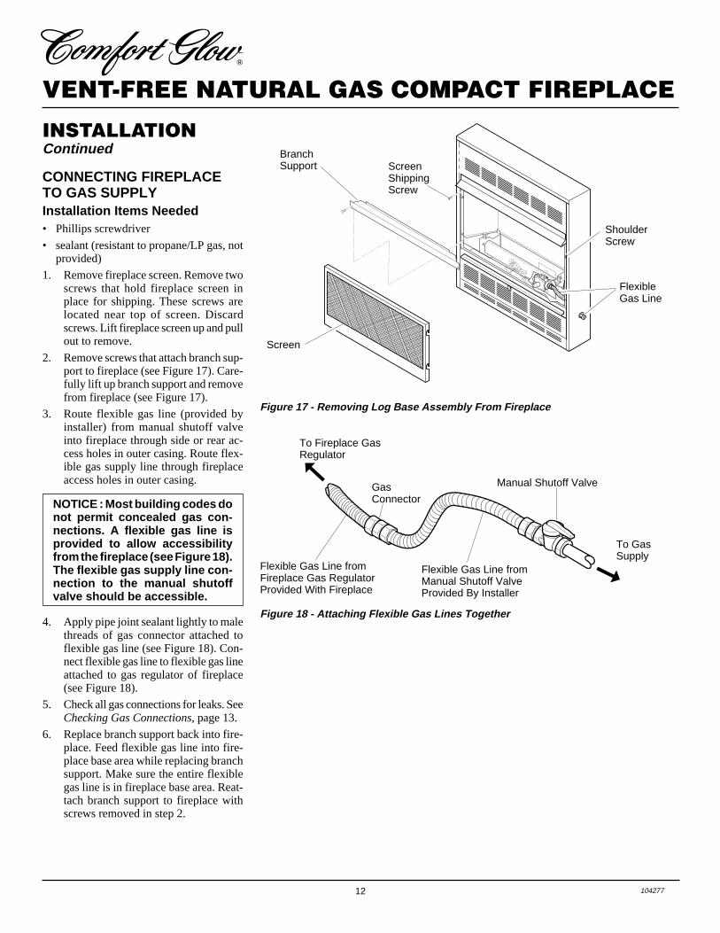
Figure 17 - Removing Log Base Assembly From Fireplace
CONNECTING FIREPLACETO GAS SUPPLYInstallation Items Needed• Phillips screwdriver
• sealant (resistant to propane/LP gas, notprovided)
1. Remove fireplace screen. Remove twoscrews that hold fireplace screen inplace for shipping. These screws arelocated near top of screen. Discardscrews. Lift fireplace screen up and pullout to remove.
2. Remove screws that attach branch sup-port to fireplace (see Figure 17). Care-fully lift up branch support and removefrom fireplace (see Figure 17).
3. Route flexible gas line (provided byinstaller) from manual shutoff valveinto fireplace through side or rear ac-cess holes in outer casing. Route flex-ible gas supply line through fireplaceaccess holes in outer casing.
4. Apply pipe joint sealant lightly to malethreads of gas connector attached toflexible gas line (see Figure 18). Con-nect flexible gas line to flexible gas lineattached to gas regulator of fireplace(see Figure 18).
5. Check all gas connections for leaks. SeeChecking Gas Connections, page 13.
6. Replace branch support back into fire-place. Feed flexible gas line into fire-place base area while replacing branchsupport. Make sure the entire flexiblegas line is in fireplace base area. Reat-tach branch support to fireplace withscrews removed in step 2.
NOTICE : Most building codes donot permit concealed gas con-nections. A flexible gas line isprovided to allow accessibilityfrom the fireplace (see Figure 18).The flexible gas supply line con-nection to the manual shutoffvalve should be accessible.
FlexibleGas Line
BranchSupport
Screen
ScreenShippingScrew
ShoulderScrew
Figure 18 - Attaching Flexible Gas Lines Together
➞Flexible Gas Line fromFireplace Gas RegulatorProvided With Fireplace
To Fireplace GasRegulator
➞GasConnector
Flexible Gas Line fromManual Shutoff ValveProvided By Installer
Manual Shutoff Valve
To GasSupply
INSTALLATIONContinued

13104277
OWNER’S MANUAL
ONPOSITI
OPOS
Pressure Testing Gas SupplyPiping System
Test Pressures In Excess Of 1/2 PSIG1. Disconnect fireplace and its individual
manual shutoff valve from gas supplypiping system. Pressures in excess of1/2 psig will damage fireplace regulator.
2. Cap off open end of gas pipe wheremanual shutoff valve was connected.
3. Pressurize supply piping system byeither using compressed air or open-ing main gas valve located on or neargas meter.
4. Check all joints of gas supply pipingsystem. Apply mixture of liquid soapand water to gas joints. Bubbles form-ing show a leak.
5. Correct all leaks at once.
6. Reconnect heater and manual shutoffvalve to gas supply. Check reconnectedfittings for leaks.
Open
Closed
ManualShutoffValve
CHECKING GASCONNECTIONS
Figure 19 - Manual Shutoff Valve
Gas Meter
Figure 20 - Checking Gas Joints
ManualShutoffValve
WARNING: Test all gas pip-ing and connections for leaksafter installing or servicing. Cor-rect all leaks at once.
WARNING: Never use an openflame to check for a leak. Apply amixture of liquid soap and waterto all joints. Bubbles forming showa leak. Correct all leaks at once.
Pressure Testing Fireplace GasConnections1. Open manual shutoff valve (see Fig-
ure 19).
2. Open main gas valve located on or neargas meter.
3. Make sure control knob of fireplace isin the OFF position.
4. Check all joints from manual shutoffvalve to thermostat gas valve (see Fig-ure 20). Apply mixture of liquid soapand water to gas joints. Bubbles form-ing show a leak.
5. Correct all leaks at once.
6. Light fireplace (see Operating Fire-place, pages 14 and 15). Check all otherinternal joints for leaks.
7. Turn off fireplace (see To Turn Off Gasto Appliance, page 15).
8. Replace front panel.
INSTALLATIONContinued
Test Pressures Equal To or Less Than1/2 PSIG1. Close manual shutoff valve (see
Figure 19).
2. Pressurize supply piping system byeither using compressed air or open-ing main gas valve located on or neargas meter.
3. Check all joints from gas meter tomanual shutoff valve (see Figure 20).Apply mixture of liquid soap and wa-ter to gas joints. Bubbles forming showa leak.
4. Correct all leaks at once.
14 104277
VENT-FREE NATURAL GAS COMPACT FIREPLACE
OPERATINGFIREPLACE
FOR YOUR SAFETYREAD BEFORE
LIGHTING
WARNING: If you do not fol-low these instructions exactly, afire or explosion may result caus-ing property damage, personalinjury or loss of life.
LIGHTINGINSTRUCTIONS
1. STOP! Read the safety informationcolumn 1.
2. Make sure manual shutoff valve isfully open.
3. Turn control knob clockwise to the OFF position.
4. Wait five (5) minutes to clear out anygas. Then smell for gas, including nearthe floor. If you smell gas, STOP! Fol-low “B” in the safety information, col-umn 1. If you don’t smell gas, go tothe next step.
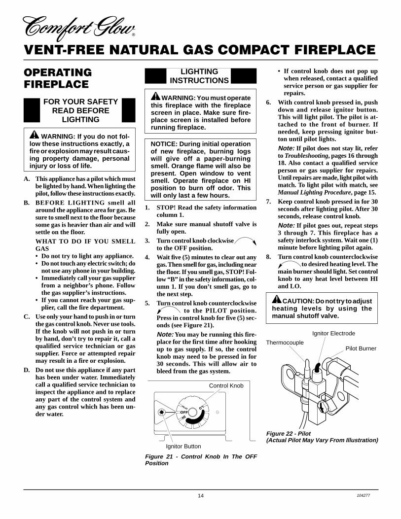
5. Turn control knob counterclockwise to the PILOT position.
Press in control knob for five (5) sec-onds (see Figure 21).Note: You may be running this fire-place for the first time after hookingup to gas supply. If so, the controlknob may need to be pressed in for30 seconds. This will allow air tobleed from the gas system.
Figure 21 - Control Knob In The OFFPosition
A. This appliance has a pilot which mustbe lighted by hand. When lighting thepilot, follow these instructions exactly.
B. BEFORE LIGHTING smell allaround the appliance area for gas. Besure to smell next to the floor becausesome gas is heavier than air and willsettle on the floor.WHAT TO DO IF YOU SMELLGAS• Do not try to light any appliance.• Do not touch any electric switch; do
not use any phone in your building.• Immediately call your gas supplier
from a neighbor’s phone. Followthe gas supplier’s instructions.
• If you cannot reach your gas sup-plier, call the fire department.
C. Use only your hand to push in or turnthe gas control knob. Never use tools.If the knob will not push in or turnby hand, don’t try to repair it, call aqualified service technician or gassupplier. Force or attempted repairmay result in a fire or explosion.
D. Do not use this appliance if any parthas been under water. Immediatelycall a qualified service technician toinspect the appliance and to replaceany part of the control system andany gas control which has been un-der water.
WARNING: You must operatethis fireplace with the fireplacescreen in place. Make sure fire-place screen is installed beforerunning fireplace.
NOTICE: During initial operationof new fireplace, burning logswill give off a paper-burningsmell. Orange flame will also bepresent. Open window to ventsmell. Operate fireplace on HIposition to burn off odor. Thiswill only last a few hours.
Ignitor Button
Control Knob
Figure 22 - Pilot(Actual Pilot May Vary From Illustration)
CAUTION: Do not try to adjustheating levels by using themanual shutoff valve.
ThermocouplePilot Burner
Ignitor Electrode
• If control knob does not pop upwhen released, contact a qualifiedservice person or gas supplier forrepairs.
6. With control knob pressed in, pushdown and release ignitor button.This will light pilot. The pilot is at-tached to the front of burner. Ifneeded, keep pressing ignitor but-ton until pilot lights.Note: If pilot does not stay lit, referto Troubleshooting, pages 16 through18. Also contact a qualified serviceperson or gas supplier for repairs.Until repairs are made, light pilot withmatch. To light pilot with match, seeManual Lighting Procedure, page 15.
7. Keep control knob pressed in for 30seconds after lighting pilot. After 30seconds, release control knob.Note: If pilot goes out, repeat steps3 through 7. This fireplace has asafety interlock system. Wait one (1)minute before lighting pilot again.
8. Turn control knob counterclockwise to desired heating level. The
main burner should light. Set controlknob to any heat level between HIand LO.

15104277
OWNER’S MANUALBURNER FLAME PATTERNFigure 25 shows a correct burner flamepattern. Figure 26 shows an incorrect burnerflame pattern. The incorrect burner flamepattern shows yellow tipping of the flame. Italso shows the flame higher than one inchabove the log.
Note: When using the fireplace the firsttime, the flame will be yellow for approxi-mately one hour until the log cures.
NOTICE: Do not mistake orangeflames with yellow tipping. Dirtor other fine particles enter thefireplace and burn causing briefpatches of orange flame.
If burner flame pattern is incorrect, as shownin Figure 26
• turn fireplace off (see To Turn Off Gas toAppliance)
• see Troubleshooting, pages 16 through 18
Figure 25 - Correct Burner Flame Pattern
Figure 26 - Incorrect Burner Flame Pattern
WARNING: If yellow tippingoccurs, your fireplace could pro-duce increased levels of carbonmonoxide. If burner flame patternshows yellow tipping, follow in-structions at bottom of this page.
Yellow Tipping
Top of Flame AboutOne Inch Above Logs
INSPECTINGBURNER
Thermocouple
Pilot Burner
Figure 23 - Correct Pilot Flame Pattern(Actual Pilot May Vary From Illustration)
Thermocouple Pilot Burner
Figure 24 - Incorrect Pilot Flame Pattern(Actual Pilot May Vary From Illustration)
Check pilot flame pattern and burner flamepattern often.
PILOT FLAME PATTERNFigure 23 shows a correct pilot flame pattern.Figure 24 shows an incorrect pilot flamepattern. The incorrect pilot flame is not touch-ing the thermocouple. This will cause thethermocouple to cool. When the thermo-couple cools, the fireplace will shut down.If pilot flame pattern is incorrect, asshown in Figure 24• turn fireplace off (see To Turn Off Gas to
Appliance)
• see Troubleshooting, pages 16 through 18
TO TURN OFF GASTO APPLIANCE
Shutting Off Fireplace1. Turn control knob clockwise
to the OFF position.2. Turn off all electric power to the ap-
pliance if service is to be performed.
Shutting Off Burner Only (pilotstays lit)
Turn control knob clockwise tothe PILOT position.
The thermostatic control used on this fire-place differs from standard thermostats.Standard thermostats simply turn on andoff the burner. The thermostat used onthis fireplace senses the room tempera-ture. The thermostat adjusts the amountof gas flow to the burner. This increases ordecreases the burner flame height. At timesthe room may exceed the set temperature.If so, the burner will shut off. The burnerwill cycle back on when room temperaturedrops below the set temperature.
The control knob can be set to any heatlevel between HI and LO.
Note: The thermostat sensing bulb mea-sures the temperature of air near the fire-place cabinet. This may not always agreewith room temperature (depending onhousing construction, installation location,room size, open air temperatures, etc.).Frequent use of your fireplace will let youdetermine your own comfort levels.
THERMOSTATCONTROL OPERATION
1. Follow steps 1 through 5 underLighting Instructions, page 14.
2. With control knob pressed in, strikematch. Hold match to pilot until pi-lot lights.
3. Keep control knob pressed in for 30seconds after lighting pilot. After 30seconds, release control knob. Nowfollow step 8, page 14.
MANUAL LIGHTINGPROCEDURE
OPERATINGFIREPLACEContinued
16 104277
VENT-FREE NATURAL GAS COMPACT FIREPLACE
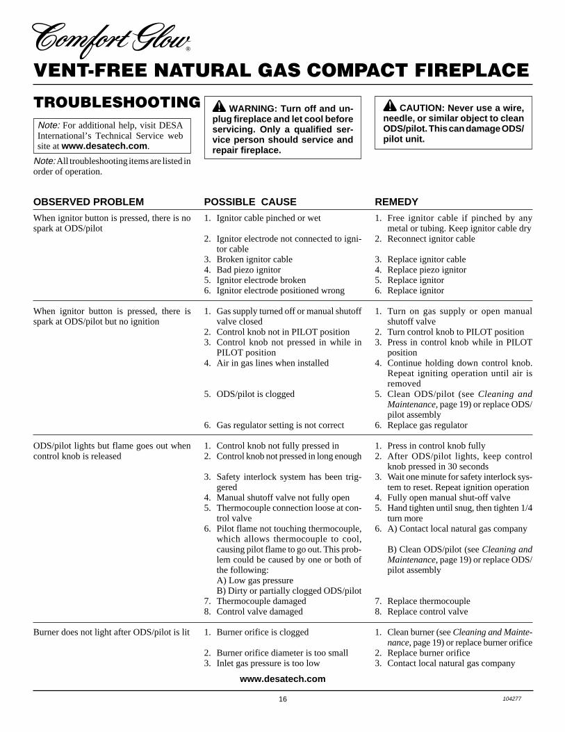
TROUBLESHOOTING
POSSIBLE CAUSE
1. Ignitor cable pinched or wet
2. Ignitor electrode not connected to igni-tor cable
3. Broken ignitor cable4. Bad piezo ignitor5. Ignitor electrode broken6. Ignitor electrode positioned wrong
1. Gas supply turned off or manual shutoffvalve closed
2. Control knob not in PILOT position3. Control knob not pressed in while in
PILOT position4. Air in gas lines when installed
5. ODS/pilot is clogged
6. Gas regulator setting is not correct
1. Control knob not fully pressed in2. Control knob not pressed in long enough
3. Safety interlock system has been trig-gered
4. Manual shutoff valve not fully open5. Thermocouple connection loose at con-
trol valve6. Pilot flame not touching thermocouple,
which allows thermocouple to cool,causing pilot flame to go out. This prob-lem could be caused by one or both ofthe following:A) Low gas pressureB) Dirty or partially clogged ODS/pilot
7. Thermocouple damaged8. Control valve damaged
1. Burner orifice is clogged
2. Burner orifice diameter is too small3. Inlet gas pressure is too low
REMEDY
1. Free ignitor cable if pinched by anymetal or tubing. Keep ignitor cable dry
2. Reconnect ignitor cable
3. Replace ignitor cable4. Replace piezo ignitor5. Replace ignitor6. Replace ignitor
1. Turn on gas supply or open manualshutoff valve
2. Turn control knob to PILOT position3. Press in control knob while in PILOT
position4. Continue holding down control knob.
Repeat igniting operation until air isremoved
5. Clean ODS/pilot (see Cleaning andMaintenance, page 19) or replace ODS/pilot assembly
6. Replace gas regulator
1. Press in control knob fully2. After ODS/pilot lights, keep control
knob pressed in 30 seconds3. Wait one minute for safety interlock sys-
tem to reset. Repeat ignition operation4. Fully open manual shut-off valve5. Hand tighten until snug, then tighten 1/4
turn more6. A) Contact local natural gas company
B) Clean ODS/pilot (see Cleaning andMaintenance, page 19) or replace ODS/pilot assembly
7. Replace thermocouple8. Replace control valve
1. Clean burner (see Cleaning and Mainte-nance, page 19) or replace burner orifice
2. Replace burner orifice3. Contact local natural gas company
OBSERVED PROBLEM
When ignitor button is pressed, there is nospark at ODS/pilot
When ignitor button is pressed, there isspark at ODS/pilot but no ignition
ODS/pilot lights but flame goes out whencontrol knob is released
Burner does not light after ODS/pilot is lit
WARNING: Turn off and un-plug fireplace and let cool beforeservicing. Only a qualified ser-vice person should service andrepair fireplace.
CAUTION: Never use a wire,needle, or similar object to cleanODS/pilot. This can damage ODS/pilot unit.
Note: For additional help, visit DESAInternational’s Technical Service website at www.desatech.com .
Note: All troubleshooting items are listed inorder of operation.
www.desatech.com
17104277
OWNER’S MANUAL
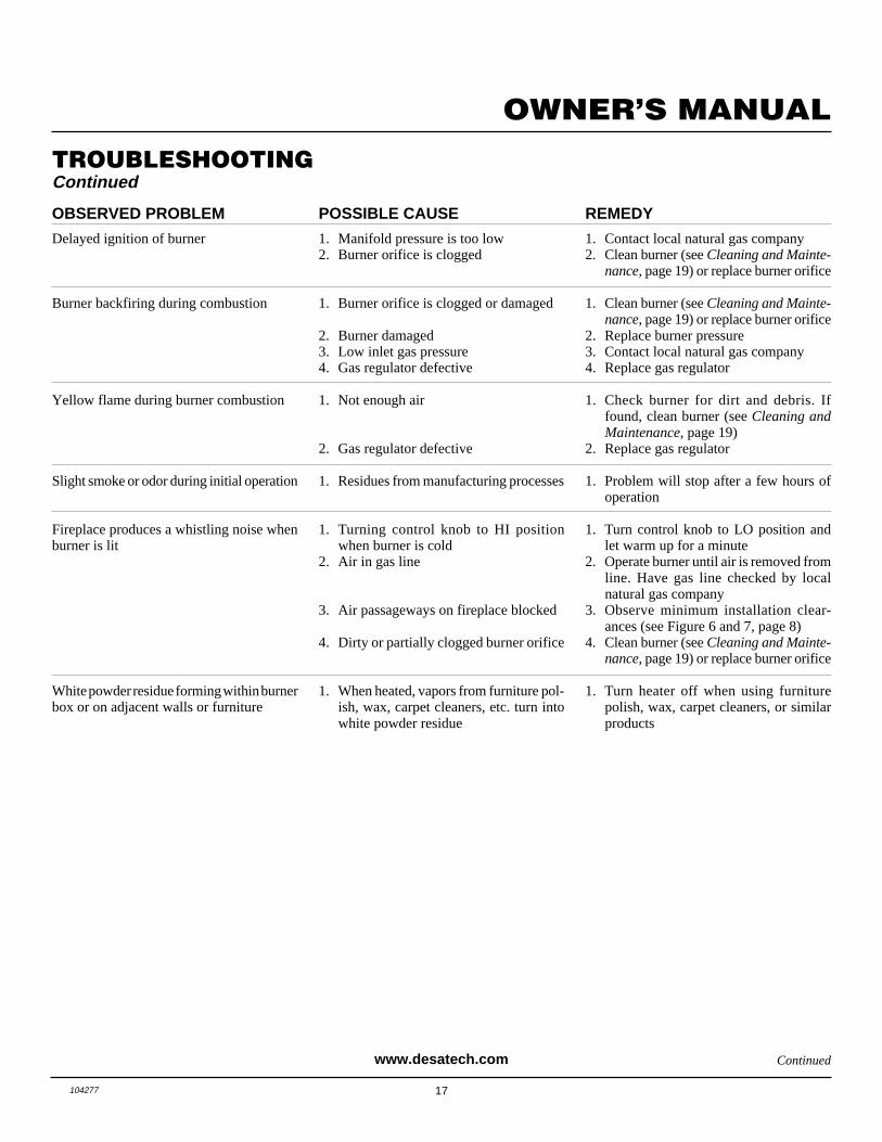
OBSERVED PROBLEM
Delayed ignition of burner
Burner backfiring during combustion
Yellow flame during burner combustion
Slight smoke or odor during initial operation
Fireplace produces a whistling noise whenburner is lit
White powder residue forming within burnerbox or on adjacent walls or furniture
REMEDY
1. Contact local natural gas company2. Clean burner (see Cleaning and Mainte-
nance, page 19) or replace burner orifice
1. Clean burner (see Cleaning and Mainte-nance, page 19) or replace burner orifice
2. Replace burner pressure3. Contact local natural gas company4. Replace gas regulator
1. Check burner for dirt and debris. Iffound, clean burner (see Cleaning andMaintenance, page 19)
2. Replace gas regulator
1. Problem will stop after a few hours ofoperation
1. Turn control knob to LO position andlet warm up for a minute
2. Operate burner until air is removed fromline. Have gas line checked by localnatural gas company
3. Observe minimum installation clear-ances (see Figure 6 and 7, page 8)
4. Clean burner (see Cleaning and Mainte-nance, page 19) or replace burner orifice
1. Turn heater off when using furniturepolish, wax, carpet cleaners, or similarproducts
POSSIBLE CAUSE
1. Manifold pressure is too low2. Burner orifice is clogged
1. Burner orifice is clogged or damaged
2. Burner damaged3. Low inlet gas pressure4. Gas regulator defective
1. Not enough air
2. Gas regulator defective
1. Residues from manufacturing processes
1. Turning control knob to HI positionwhen burner is cold
2. Air in gas line
3. Air passageways on fireplace blocked
4. Dirty or partially clogged burner orifice
1. When heated, vapors from furniture pol-ish, wax, carpet cleaners, etc. turn intowhite powder residue
TROUBLESHOOTINGContinued
Continuedwww.desatech.com

18 104277
VENT-FREE NATURAL GAS COMPACT FIREPLACE
TROUBLESHOOTINGContinued
WARNING: If you smell gas• Shut off gas supply.• Do not try to light any appliance.• Do not touch any electrical switch; do not use any phone in your
building.• Immediately call your gas supplier from a neighbor’s phone. Follow the
gas supplier’s instructions.• If you cannot reach your gas supplier, call the fire department.
IMPORTANT: Operating fireplace where impurities in air exist may create odors. Cleaningsupplies, paint, paint remover, cigarette smoke, cements and glues, new carpet or textiles,etc., create fumes. These fumes may mix with combustion air and create odors.
POSSIBLE CAUSE
1. Metal expanding while heating or con-tracting while cooling
1. Fireplace burning vapors from paint, hairspray, glues, etc. (see IMPORTANTstatement above)
2. Gas leak. See Warning statement attop of page
1. Not enough fresh air is available2. Low line pressure3. ODS/pilot is partially clogged
1. Gas leak. See Warning statement attop of page
2. Control valve defective
1. Foreign matter between control valveand burner
2. Gas leak. See Warning statement attop of page
1. Not enough combustion/ventilation air
OBSERVED PROBLEM
Fireplace produces a clicking/ticking noisejust after burner is lit or shut off
Fireplace produces unwanted odors
Fireplace shuts off in use (ODS operates)
Gas odor even when control knob is in OFFposition
Gas odor during combustion
Moisture/condensation noticed on windows
REMEDY
1. This is common with most fireplaces. Ifnoise is excessive, contact qualified ser-vice person
1. Ventilate room. Stop using odor caus-ing products while fireplace is running
2. Locate and correct all leaks (see Check-ing Gas Connections, page 13)
1. Open window and/or door for ventilation2. Contact local natural gas company3. Clean ODS/pilot (see Cleaning and
Maintenance, page 19)
1. Locate and correct all leaks (see Check-ing Gas Connections, page 13)
2. Replace control valve
1. Take apart gas tubing and remove for-eign matter
2. Locate and correct all leaks (see Check-ing Gas Connections, page 13)
1. Refer to Air for Combustion and Venti-lation requirements (page 5)
www.desatech.com
19104277
OWNER’S MANUAL
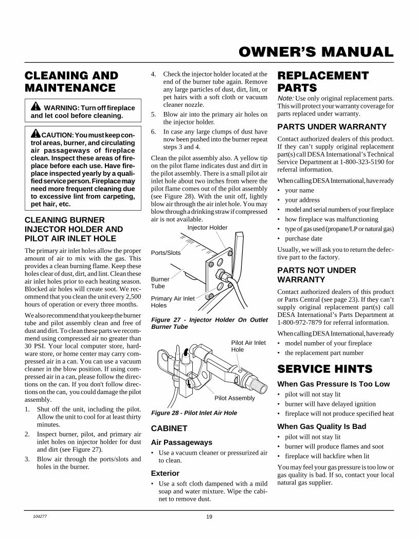
REPLACEMENTPARTSNote: Use only original replacement parts.This will protect your warranty coverage forparts replaced under warranty.
PARTS UNDER WARRANTYContact authorized dealers of this product.If they can’t supply original replacementpart(s) call DESA International’s TechnicalService Department at 1-800-323-5190 forreferral information.
When calling DESA International, have ready
• your name
• your address
• model and serial numbers of your fireplace
• how fireplace was malfunctioning
• type of gas used (propane/LP or natural gas)
• purchase date
Usually, we will ask you to return the defec-tive part to the factory.
PARTS NOT UNDERWARRANTYContact authorized dealers of this productor Parts Central (see page 23). If they can’tsupply original replacement part(s) callDESA International’s Parts Department at1-800-972-7879 for referral information.
When calling DESA International, have ready
• model number of your fireplace
• the replacement part number
CLEANING ANDMAINTENANCE
CABINET
Air Passageways• Use a vacuum cleaner or pressurized air
to clean.
Exterior• Use a soft cloth dampened with a mild
soap and water mixture. Wipe the cabi-net to remove dust.
WARNING: Turn off fireplaceand let cool before cleaning.
CAUTION: You must keep con-trol areas, burner, and circulatingair passageways of fireplaceclean. Inspect these areas of fire-place before each use. Have fire-place inspected yearly by a quali-fied service person. Fireplace mayneed more frequent cleaning dueto excessive lint from carpeting,pet hair, etc.
When Gas Pressure Is Too Low• pilot will not stay lit
• burner will have delayed ignition
• fireplace will not produce specified heat
When Gas Quality Is Bad• pilot will not stay lit
• burner will produce flames and soot
• fireplace will backfire when lit
You may feel your gas pressure is too low orgas quality is bad. If so, contact your localnatural gas supplier.
SERVICE HINTS
CLEANING BURNERINJECTOR HOLDER ANDPILOT AIR INLET HOLEThe primary air inlet holes allow the properamount of air to mix with the gas. Thisprovides a clean burning flame. Keep theseholes clear of dust, dirt, and lint. Clean theseair inlet holes prior to each heating season.Blocked air holes will create soot. We rec-ommend that you clean the unit every 2,500hours of operation or every three months.
We also recommend that you keep the burnertube and pilot assembly clean and free ofdust and dirt. To clean these parts we recom-mend using compressed air no greater than30 PSI. Your local computer store, hard-ware store, or home center may carry com-pressed air in a can. You can use a vacuumcleaner in the blow position. If using com-pressed air in a can, please follow the direc-tions on the can. If you don't follow direc-tions on the can, you could damage the pilotassembly.
1. Shut off the unit, including the pilot.Allow the unit to cool for at least thirtyminutes.
2. Inspect burner, pilot, and primary airinlet holes on injector holder for dustand dirt (see Figure 27).
3. Blow air through the ports/slots andholes in the burner.
Figure 27 - Injector Holder On OutletBurner Tube
4. Check the injector holder located at theend of the burner tube again. Removeany large particles of dust, dirt, lint, orpet hairs with a soft cloth or vacuumcleaner nozzle.
5. Blow air into the primary air holes onthe injector holder.
6. In case any large clumps of dust havenow been pushed into the burner repeatsteps 3 and 4.
Clean the pilot assembly also. A yellow tipon the pilot flame indicates dust and dirt inthe pilot assembly. There is a small pilot airinlet hole about two inches from where thepilot flame comes out of the pilot assembly(see Figure 28). With the unit off, lightlyblow air through the air inlet hole. You mayblow through a drinking straw if compressedair is not available.
BurnerTube
Injector Holder
Primary Air InletHoles
Figure 28 - Pilot Inlet Air Hole
Pilot Assembly
Pilot Air InletHole
Ports/Slots

20 104277
VENT-FREE NATURAL GAS COMPACT FIREPLACE
17
23
29
32
8
14
36
37
13
7 8
42
33
114
17 10
4
7
8
8
30
3 1
2
9
19
6
22
31
2140
41
38
39
16
15
182428
5
34
2625
20
35-1
4
35-2
12
24
12-125
14
8
3
27
12-1
12-2
ILLUSTRATEDPARTSBREAKDOWNCGCF26TNA
21104277
OWNER’S MANUAL
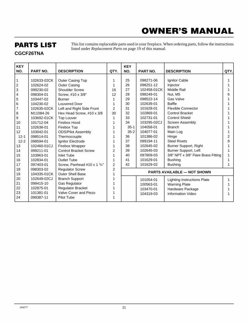
PARTS LIST This list contains replaceable parts used in your fireplace. When ordering parts, follow the instructionslisted under Replacement Parts on page 19 of this manual.
CGCF26TNA
KEYNO. PART NO. DESCRIPTION QTY.
1 102633-02CK Outer Casing Top 12 102624-02 Outer Casing 13 099230-02 Shoulder Screw 164 098304-01 Screw, #10 x 3/8" 125 103447-02 Burner 16 104230-02 Louvered Door 17 102635-02CK Left and Right Side Front 28 M11084-26 Hex Head Screw, #10 x 3/8 309 103692-01CK Top Louver 110 101712-04 Firebox Hood 111 102638-01 Firebox Top 112 103042-01 ODS/Pilot Assembly 1 12-1 098514-01 Thermocouple 1 12-2 098594-01 Ignitor Electrode 113 102460-01CJ Firebox Wrapper 114 099211-01 Control Bracket Screw 215 103963-01 Inlet Tube 116 102834-01 Outlet Tube 117 097403-01 Screw, Panhead #10 x 1 3/4" 218 098303-02 Regulator Screw 219 104335-01CK Outer Shell Base 120 102649-02CJ Branch Support 121 099415-10 Gas Regulator 122 102875-01 Regulator Bracket 123 101381-01 Valve Cover and Piezo 124 099387-11 Pilot Tube 1
KEYNO. PART NO. DESCRIPTION QTY.
25 098271-06 Ignitor Cable 126 098251-12 Injector 127 102458-01CK Middle Rail 128 098249-01 Nut, M5 629 098522-14 Gas Valve 130 102639-01 Baffle 131 101628-01 Flexible Connector 132 102869-01 Control Bracket 133 102731-01 Control Shield 134 103295-02CJ Screen Assembly 1 35-1 104058-01 Branch 1 35-2 104077-01 Main Log 136 101386-02 Hinge 237 099194-11 Steel Rivets 838 102645-02 Burner Support, Right 139 102645-03 Burner Support, Left 140 097809-03 3/8" NPT x 3/8" Flare Brass Fitting 141 101629-01 Bushing 142 101629-02 Bushing 1
PARTS AVAILABLE — NOT SHOWN
101054-01 Lighting Instructions Plate 1100563-01 Warning Plate 1103470-01 Hardware Package 1104319-03 Information Video 1
22 104277
VENT-FREE NATURAL GAS COMPACT FIREPLACE
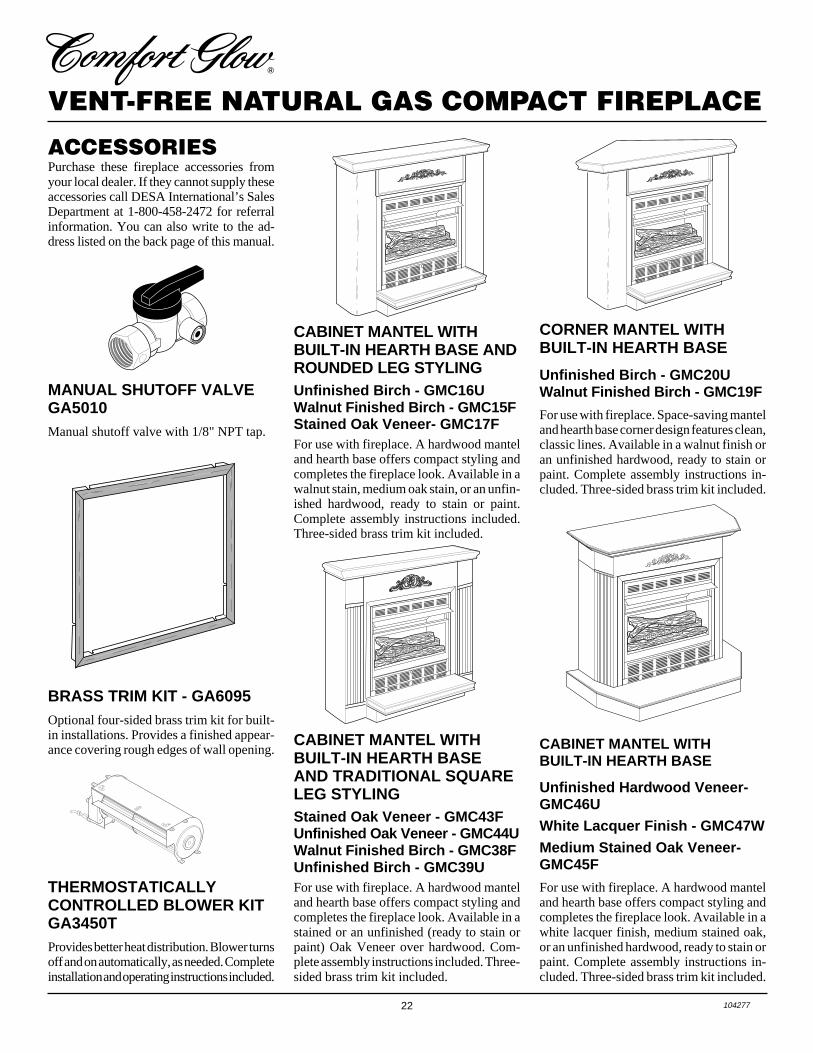
ACCESSORIESPurchase these fireplace accessories fromyour local dealer. If they cannot supply theseaccessories call DESA International’s SalesDepartment at 1-800-458-2472 for referralinformation. You can also write to the ad-dress listed on the back page of this manual.
MANUAL SHUTOFF VALVEGA5010Manual shutoff valve with 1/8" NPT tap.
THERMOSTATICALLYCONTROLLED BLOWER KITGA3450TProvides better heat distribution. Blower turnsoff and on automatically, as needed. Completeinstallation and operating instructions included.
BRASS TRIM KIT - GA6095Optional four-sided brass trim kit for built-in installations. Provides a finished appear-ance covering rough edges of wall opening.
CABINET MANTEL WITHBUILT-IN HEARTH BASE ANDROUNDED LEG STYLINGUnfinished Birch - GMC16UWalnut Finished Birch - GMC15FStained Oak Veneer- GMC17FFor use with fireplace. A hardwood manteland hearth base offers compact styling andcompletes the fireplace look. Available in awalnut stain, medium oak stain, or an unfin-ished hardwood, ready to stain or paint.Complete assembly instructions included.Three-sided brass trim kit included.
CORNER MANTEL WITHBUILT-IN HEARTH BASE
Unfinished Birch - GMC20UWalnut Finished Birch - GMC19F
For use with fireplace. Space-saving manteland hearth base corner design features clean,classic lines. Available in a walnut finish oran unfinished hardwood, ready to stain orpaint. Complete assembly instructions in-cluded. Three-sided brass trim kit included.
CABINET MANTEL WITHBUILT-IN HEARTH BASEAND TRADITIONAL SQUARELEG STYLINGStained Oak Veneer - GMC43FUnfinished Oak Veneer - GMC44UWalnut Finished Birch - GMC38FUnfinished Birch - GMC39UFor use with fireplace. A hardwood manteland hearth base offers compact styling andcompletes the fireplace look. Available in astained or an unfinished (ready to stain orpaint) Oak Veneer over hardwood. Com-plete assembly instructions included. Three-sided brass trim kit included.
CABINET MANTEL WITHBUILT-IN HEARTH BASE
Unfinished Hardwood Veneer-GMC46UWhite Lacquer Finish - GMC47WMedium Stained Oak Veneer-GMC45F
For use with fireplace. A hardwood manteland hearth base offers compact styling andcompletes the fireplace look. Available in awhite lacquer finish, medium stained oak,or an unfinished hardwood, ready to stain orpaint. Complete assembly instructions in-cluded. Three-sided brass trim kit included.
23104277
OWNER’S MANUAL
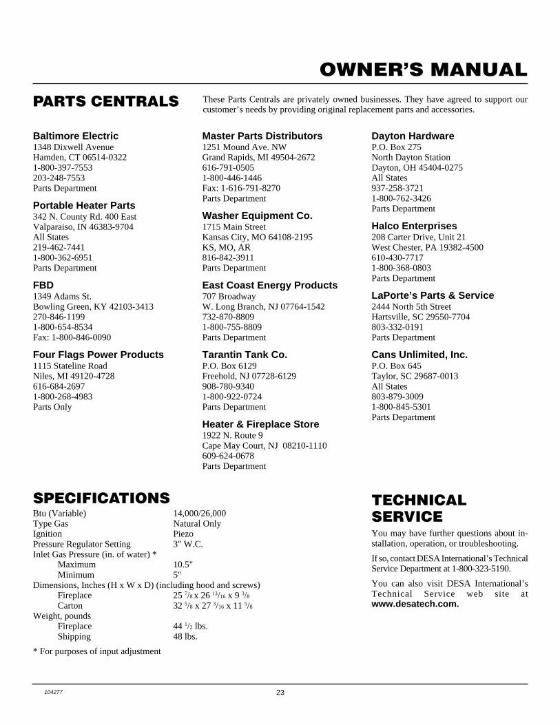
PARTS CENTRALS
Master Parts Distributors1251 Mound Ave. NWGrand Rapids, MI 49504-2672616-791-05051-800-446-1446Fax: 1-616-791-8270Parts Department
Washer Equipment Co.1715 Main StreetKansas City, MO 64108-2195KS, MO, AR816-842-3911Parts Department
East Coast Energy Products707 BroadwayW. Long Branch, NJ 07764-1542732-870-88091-800-755-8809Parts Department
Tarantin Tank Co.P.O. Box 6129Freehold, NJ 07728-6129908-780-93401-800-922-0724Parts Department
Heater & Fireplace Store1922 N. Route 9Cape May Court, NJ 08210-1110609-624-0678Parts Department
Baltimore Electric1348 Dixwell AvenueHamden, CT 06514-03221-800-397-7553203-248-7553Parts Department
Portable Heater Parts342 N. County Rd. 400 EastValparaiso, IN 46383-9704All States219-462-74411-800-362-6951Parts Department
FBD1349 Adams St.Bowling Green, KY 42103-3413270-846-11991-800-654-8534Fax: 1-800-846-0090
Four Flags Power Products1115 Stateline RoadNiles, MI 49120-4728616-684-26971-800-268-4983Parts Only
These Parts Centrals are privately owned businesses. They have agreed to support ourcustomer’s needs by providing original replacement parts and accessories.
Dayton HardwareP.O. Box 275North Dayton StationDayton, OH 45404-0275All States937-258-37211-800-762-3426Parts Department
Halco Enterprises208 Carter Drive, Unit 21West Chester, PA 19382-4500610-430-77171-800-368-0803Parts Department
LaPorte’s Parts & Service2444 North 5th StreetHartsville, SC 29550-7704803-332-0191Parts Department
Cans Unlimited, Inc.P.O. Box 645Taylor, SC 29687-0013All States803-879-30091-800-845-5301Parts Department
SPECIFICATIONSBtu (Variable) 14,000/26,000Type Gas Natural OnlyIgnition PiezoPressure Regulator Setting 3" W.C.Inlet Gas Pressure (in. of water) *
Maximum 10.5"Minimum 5"
Dimensions, Inches (H x W x D) (including hood and screws)Fireplace 25 7/8
x 26 13/16 x 9 3/8Carton 32 5/8 x 27 3/16 x 11 5/8
Weight, poundsFireplace 44 1/2 lbs.Shipping 48 lbs.
* For purposes of input adjustment
TECHNICALSERVICEYou may have further questions about in-stallation, operation, or troubleshooting.
If so, contact DESA International’s TechnicalService Department at 1-800-323-5190.
You can also visit DESA International’sTechnical Service web site atwww.desatech.com.
2701 Industrial DriveP.O. Box 90004Bowling Green, KY 42102-9004
www.desatech.com
104277-01Rev. D10/99
INTERNATIONAL
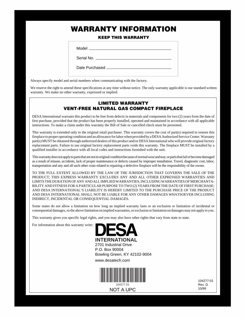
LIMITED WARRANTYVENT-FREE NATURAL GAS COMPACT FIREPLACE
DESA International warrants this product to be free from defects in materials and components for two (2) years from the date offirst purchase, provided that the product has been properly installed, operated and maintained in accordance with all applicableinstructions. To make a claim under this warranty the Bill of Sale or cancelled check must be presented.
This warranty is extended only to the original retail purchaser. This warranty covers the cost of part(s) required to restore thisfireplace to proper operating condition and an allowance for labor when provided by a DESA Authorized Service Center. Warrantypart(s) MUST be obtained through authorized dealers of this product and/or DESA International who will provide original factoryreplacement parts. Failure to use original factory replacement parts voids this warranty. The fireplace MUST be installed by aqualified installer in accordance with all local codes and instructions furnished with the unit.
This warranty does not apply to parts that are not in original condition because of normal wear and tear, or parts that fail or become damagedas a result of misuse, accidents, lack of proper maintenance or defects caused by improper installation. Travel, diagnostic cost, labor,transportation and any and all such other costs related to repairing a defective fireplace will be the responsibility of the owner.
TO THE FULL EXTENT ALLOWED BY THE LAW OF THE JURISDICTION THAT GOVERNS THE SALE OF THEPRODUCT; THIS EXPRESS WARRANTY EXCLUDES ANY AND ALL OTHER EXPRESSED WARRANTIES ANDLIMITS THE DURATION OF ANY AND ALL IMPLIED WARRANTIES, INCLUDING WARRANTIES OF MERCHANTA-BILITY AND FITNESS FOR A PARTICULAR PURPOSE TO TWO (2) YEARS FROM THE DATE OF FIRST PURCHASE;AND DESA INTERNATIONAL’S LIABILITY IS HEREBY LIMITED TO THE PURCHASE PRICE OF THE PRODUCTAND DESA INTERNATIONAL SHALL NOT BE LIABLE FOR ANY OTHER DAMAGES WHATSOEVER INCLUDINGINDIRECT, INCIDENTAL OR CONSEQUENTIAL DAMAGES.
Some states do not allow a limitation on how long an implied warranty lasts or an exclusion or limitation of incidental orconsequential damages, so the above limitation on implied warranties, or exclusion or limitation on damages may not apply to you.
This warranty gives you specific legal rights, and you may also have other rights that vary from state to state.
For information about this warranty write:
KEEP THIS WARRANTY
Model
Serial No.
Date Purchased
Always specify model and serial numbers when communicating with the factory.
We reserve the right to amend these specifications at any time without notice. The only warranty applicable is our standard writtenwarranty. We make no other warranty, expressed or implied.
WARRANTY INFORMATION
NOT A UPC104277 01