Embed Size (px)
Citation preview

8/14/2019 Lecture-Air Movement+Natural Vent
http://slidepdf.com/reader/full/lecture-air-movementnatural-vent 1/15
Lecture: Air Movement and Natural Ventilation1. Basic Concepts
1.1 Natural ventilation 1.2 Mechanical ventilation 1.3 Purposes of ventilation
2. Principles of Natural Ventilation 2.1 Wind effect 2.2 Stack effect 2.3 Combined effect of wind and temperature difference
3. Design for Natural Ventilation 3.1 Ventilation rates 3.2 Flow caused by wind 3.3 Flow caused by thermal forces 3.4 Guidelines for natural ventilation
4. Infiltration and Air Leakage 4.1 Air leakage area and performance 4.2 Estimation of infiltration rates 4.3 Air leakage of building components
Further Reading 1. Basic Concepts VENTILATION is the process by which fresh air is introduced and ventilatedair is removed from an occupied space. The primary aim of ventilation is topreserve the qualities of air. Sometimes, ventilation may also be used to lower the temperature inside an occupied area. 1.1 Natural ventilation Natural ventilation is the process of supplying and removing air by means of
purpose-provided aperture (such as openable windows, ventilators andshafts) and the natural forces of wind and temperature-difference pressures.

8/14/2019 Lecture-Air Movement+Natural Vent
http://slidepdf.com/reader/full/lecture-air-movementnatural-vent 2/15
Natural ventilation may be divided into two categories: Controlled natural ventilation is intentional displacement of air through
specified openings such as windows, doors, and ventilations by using naturalforces (usually by pressures from wind and/or indoor-outdoor temperature
differences). It is usually controlled to some extent by the occupant. Infiltration is the uncontrolled random flow of air through unintentional
openings driven by wind, temperature-difference pressures and/or appliance-induced pressures across the building envelope. In contrast to controllednatural ventilation, infiltration cannot be so controlled and is less desirablethan other ventilation strategies, but it is a main source of ventilation inenvelope-dominated buildings. 1.2 Mechanical ventilation Mechanical or forced ventilation is the process of supplying and removing air by means of mechanical devices, such as fans. It may be arranged to provide
either supply, extract or balanced ventilation for an occupied space. There are also specialised areas in which ventilation is vital, such asventilation for industrial processes, mines, tunnels and undergrounddevelopment. However, in this lecture we will focus only on natural ventilation.
1.3 Purposes of ventilation Maintaining human comfort and health are two key reasons for providingventilation in buildings. To achieve these purposes, a ventilation system
should be able to meet the following criteria:
provide sufficient supply of air/oxygen for the physiological needs of humanbeings (a minimum of 0.2 l/s/person is required for breathing purpose) and/or livestock;
provide sufficient supply of air/oxygen for industrial, agricultural and other processes (for example, provision of oxygen for burning and combustionprocesses);
remove the products of respiration and bodily odour (including those fromsmoking) of human and/or animal occupants;
remove contaminants or harmful chemicals generated by processes or
from building materials; remove heat generated by people, lighting and equipment inside theoccupied space;
create some degree of air movement which is essential for feelings of freshness and comfort (usually a velocity of 0.1 to 0.3 m/s is required). 2. Principles of Natural Ventilation For air to move into and out of a building, a pressure difference between theinside and outside of the building is required. The resistance to flow of air through the building will affect the actual air flow rate. In general, controllednatural ventilation and infiltration are driven by pressure difference across thebuilding envelope. The pressure difference is caused by:

8/14/2019 Lecture-Air Movement+Natural Vent
http://slidepdf.com/reader/full/lecture-air-movementnatural-vent 3/15
• wind (or wind effect); • difference in air density due to temperature difference between indoor
and outdoor air (stack or chimney effect); or • combination of both wind and stack effects.
2.1 Wind effect When air flow is due to wind, air enters through openings in the windwardwalls, and leaves through openings in the leeward walls. The pressuredistribution patterns due to wind in a number of cases are illustrated in Figure1.
Figure 1 Air flow around a building
Wind pressures are generally high/positive on the windward side of a buildingand low/negative on the leeward side. The occurrence and change of windpressures on building surfaces depend on:
• wind speed and wind direction relative to the building; •
the location and surrounding environment of the building; and • shape of the building.

8/14/2019 Lecture-Air Movement+Natural Vent
http://slidepdf.com/reader/full/lecture-air-movementnatural-vent 4/15
Mathematically, pressure on building surfaces may be expressed as: (1)
where P w = mean pressure on the building surface (N/m2 or Pa)P o = static pressure in undistributed wind (N/m2 or Pa)
v w = mean wind velocity (m/s)= density of air (kg/m3)
C p = surface pressure coefficient
Few data exist on pressure coefficients for buildings of different form anddegree of shelter. For buildings of simple form which stand alone by itself, or are much higher than surrounding buildings and obstruction, the BritishStandards BS5925 gives average surface pressure coefficients. For a building with numerous partitions and openings, it is under various
pressures depending on the relative sizes of the openings and the winddirection. With large openings on the windward face, the building tends to beunder positive pressure. The reverse is true if the openings are smaller thanthose downstream. 2.2 Stack effect When air movement is due to temperature difference between the indoor andoutdoor, the flow of air is in the vertical direction and is along the path of leastresistance. The temperature difference causes density differentials, andtherefore pressure differences, that drive the air to move. During the winter
season (see Figure 2a), the following stack effect occurs: • indoor temperature is higher than outdoor temperature; • the warmer air in building then rises up; • the upward air movement produces negative indoor pressure at the
bottom; • positive indoor pressure is created on the top; • warmer air flows out of the building near the top; and • the air is replaces by colder outside air that enters the building near its
base.

8/14/2019 Lecture-Air Movement+Natural Vent
http://slidepdf.com/reader/full/lecture-air-movementnatural-vent 5/15
Figure 2 Stack effect
During the summer season (see Figure 2b), the reverse occurs when indoor
temperature is lower than outdoor temperature. Figure 3 shows stack effectthat may occur in different forms of buildings, including a building with nointernal partition, a building with airtight separation of each storey, and anideal building with vertical shafts and horizontal openings.
Figure 3 Stack effect and pressure distribution in various buildings
When thermal force is acting alone, a neutral pressure level (NPL) exists,where the interior and exterior pressures are equal. At all other levels, thepressure difference between the interior and exterior depends on the distancefrom the neutral pressure level and the difference between the densities of inside and outside air.

8/14/2019 Lecture-Air Movement+Natural Vent
http://slidepdf.com/reader/full/lecture-air-movementnatural-vent 6/15
(2)
where P s = pressure difference due to stack effect (N/m2 or Pa)
= density of air (kg/m3)
g = gravitational constant = 9.81 m/s2
h = height of observation (m)hneutral = height of neutral pressure level (m)
T = absolute temperature (K) (subscripts i = inside and o =outside)
2.3 Combined effect of wind and temperature difference In most cases, natural ventilation depends on a combined force of wind andstack effects. The pressure patterns for actual buildings continually changewith the relative magnitude of thermal and wind forces. Figure 4 shows the
combined effect of wind and thermal forces. The pressures due to each effectare added together to determine the total pressure difference across thebuilding envelope.
Figure 4 Combined effect of wind and thermal forces
The relative importance of the wind and stack pressures in a building dependson building height, internal resistance to vertical air flow, location and flowresistance characteristics of envelope openings, local terrain, and theimmediate shielding of the building structure.
3. Design for Natural Ventilation The design of controlled natural ventilation systems requires identification of the prevailing wind direction, the strategic orientations and positions of openings on the building envelope. These openings include windows, doors,roof ventilators, skylights, vent shafts, and so forth. 3.1 Ventilation rates

8/14/2019 Lecture-Air Movement+Natural Vent
http://slidepdf.com/reader/full/lecture-air-movementnatural-vent 7/15
When designing a ventilation system, the ventilation rates are required todetermine the sizes of fans, openings, and air ducts. The methods that can beused to determine the ventilation rates include: (a) Maximum allowable concentration of contaminants A decay equation can be used to describe the steady-state conditions of contaminant concentrations and ventilation rate, like this:
C i = C o + F / Q (3)where C i = maximum allowable concentration of contaminants
C o = concentration of contaminants in outdoor air
F = rate of generation of contaminants inside the occupied space(l/s)
Q = ventilation rate (l/s)
(b) Heat generation The ventilation rate required to remove heat from an occupied space is givenby:
(4)
where H = heat generation inside the space (W) Q = ventilation rate (l/s)c p = specific heat capacity of air (J/kg.K)
= density of air (kg/m3)T i = indoor air temperature (K)T
o= outdoor air temperature (K)
(c) Air change rates Most related professional institutes and authorities have set up recommendedventilation rates, expressed in air change per hour, for various situations. Theventilation rate is related to the air change rate by the following equation:
(5)
where Q = ventilation rate (l/s)
V = concentration of contaminants in outdoor air
ACH = air change per hour
Table 1 gives some recommended air change rates for typical spaces. Table 2provides some examples of outdoor air requirements for ventilation.

8/14/2019 Lecture-Air Movement+Natural Vent
http://slidepdf.com/reader/full/lecture-air-movementnatural-vent 8/15
Table 1 Recommended air change rates Space Air change rates per hour
Carparks 6
Kitchen 20 - 60Lavatory 15
Bathrooms 6
Boiler rooms 15 - 30
Table 2 Outdoor air requirements for ventilation Application Estimated maximum occupancy
(persons per 100 m2 floor area)Outdoor air
requirements(l/s/person)
Offices - office space 7 10
- conferenceroom
50 10
Retail's Stores
- street level 30 5
- upper floors/arcades
20 5
Education
- classroom 50 8
- auditorium 150 8
- library 20 8
Hospitals
- patient rooms 10 13
- operatingrooms
20 15
Note: Data source: ASHRAE Standard 62-1989, Ventilation for AcceptableIndoor Air Quality . 3.2 Flow caused by wind Major factors affecting ventilation wind forces include:
• average wind speed; • prevailing wind direction; • seasonal and daily variation in wind speed and direction; • local obstructing objects, such as nearby buildings and trees; • position and characteristics of openings through which air flows; and • distribution of surface pressure coefficients for the wind.
8/14/2019 Lecture-Air Movement+Natural Vent
http://slidepdf.com/reader/full/lecture-air-movementnatural-vent 9/15
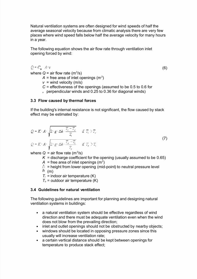
Natural ventilation systems are often designed for wind speeds of half theaverage seasonal velocity because from climatic analysis there are very fewplaces where wind speed falls below half the average velocity for many hoursin a year. The following equation shows the air flow rate through ventilation inletopening forced by wind:
(6)
where Q = air flow rate (m3/s) A = free area of inlet openings (m2)v = wind velocity (m/s)C
v
= effectiveness of the openings (assumed to be 0.5 to 0.6 for perpendicular winds and 0.25 to 0.36 for diagonal winds)
3.3 Flow caused by thermal forces If the building's internal resistance is not significant, the flow caused by stackeffect may be estimated by:
(7)
where Q = air flow rate (m3/s)K = discharge coefficient for the opening (usually assumed to be 0.65) A = free area of inlet openings (m2)
h= height from lower opening (mid-point) to neutral pressure level(m)
T i = indoor air temperature (K)T o = outdoor air temperature (K)
3.4 Guidelines for natural ventilation The following guidelines are important for planning and designing naturalventilation systems in buildings:
• a natural ventilation system should be effective regardless of winddirection and there must be adequate ventilation even when the winddoes not blow from the prevailing direction;
• inlet and outlet openings should not be obstructed by nearby objects; • windows should be located in opposing pressure zones since this
usually will increase ventilation rate; • a certain vertical distance should be kept between openings for
temperature to produce stack effect;

8/14/2019 Lecture-Air Movement+Natural Vent
http://slidepdf.com/reader/full/lecture-air-movementnatural-vent 10/15
• openings at the same level and near the ceiling should be avoidedsince much of the air flow may bypass the occupied zone;
• architectural elements like wingwalls, parapets and overhangs may beused to promote air flow into the building;
• topography, landscaping, and surrounding buildings should be used to
redirect airflow and give maximum exposure to breezes; • in hot, humid climates, air velocities should be maximised in the
occupied zones for bodily cooling; • to admit wind air flow, the long façade of the building and the door and
window openings should be oriented with respect to the prevailing winddirection;
• if possible, window openings should be accessible to and operable byoccupants;
• vertical shafts and open staircases may be used to increase andgenerate stack effect;
• openings in the vicinity of the neutral pressure level may be reducedsince they are less effective for thermally induced ventilation;
• if inlet and outlet openings are of nearly equal areas, a balanced andgreater ventilation can be obtained.
3.5 Barriers to the application of natural ventilation A successful application of natural ventilation strategies is only possible whenthere are no problems in many areas at various levels from the design stageto actual operating demands placed on the building users (Allard, 1998).These potential barriers include:
• Barriers during building operations o Safety concerns o Noise from outdoor o Dust and air pollution o Solar shading covering the openings o Draught prevention o Knowledge of the users about how to take the best advantage of
natural ventilation • Barriers during building design
o Building and fire regulations o Need for acoustic protection o Difficult to predict pattern of use o Devices for shading, privacy & daylighting may hamper the free
flow of air o Problems with automatic controls in openings o lack of suitable, reliable design tools
• Other barriers o Impact on architectural & envelope design o Fluctuation of the indoor conditions o Design a naturally ventilated building requires more work but
could reduce mechanical system (design fee on a fixedpercentage of system's cost)

8/14/2019 Lecture-Air Movement+Natural Vent
http://slidepdf.com/reader/full/lecture-air-movementnatural-vent 11/15
o Increase risk for designers o Lack of suitable standards
4. Infiltration and Air Leakage Infiltration is the uncontrolled flow of air through openings in the buildingenvelope driven by pressure differences across the building shell. The surfacepressure driving the air flow include:
wind pressure; pressures arising from temperature difference between indoor and outdoor;
and pressures resulting from operation of mechanical exhaust.
The infiltration rate of a building depends on weather conditions, equipmentoperation and occupant activities. The characteristics of infiltration air flowmay be determined by measuring the air leakage of the building envelopewhich describes the relative tightness of a building. Typical leakage rates arearound 6 to 10 air changes per hour at 50 Pa pressure difference.Control of infiltration is needed to assure indoor thermal comfort and tominimise building energy use. Normally, infiltration may be lessened byreducing the surface pressures driving the air flow, for instance, throughchanging the landscaping in the vicinity of the building. A more commonmethod is to reduce the air leakage of the building shell (for example,increase air tightness).4.1 Air leakage area and performanceAir leakage is a measure of the air tightness of the building envelope. In
practical building design, the air tightness of the whole building or itscomponents is expressed as a leakage rate (in air change per hour), or an air leakage area.
Building air leakage area is a physical property of a building determined by itsdesign, construction, seasonal effects, and deterioration over time. The larger the air leakage, the larger its infiltration rate. However, no simple relationshipexists between a building’s air tightness and its air exchange rate, althoughsome empirical methods have been developed to estimate the values. The air leakage in buildings may be determined by pressurisation testing or
tracer gas measurement. Ratings for air tightness have been established insome standards based on air flow rates predicted at particular referencepressures and test conditions. In some cases, the predicted air flow rate isconverted to an equivalent or effective air leakage area using the followingequation (which is derived from the Bernoulli equation for incompressible fluidflow):
(8)
where AL = effective air leakage area (cm2)
8/14/2019 Lecture-Air Movement+Natural Vent
http://slidepdf.com/reader/full/lecture-air-movementnatural-vent 12/15
Qr = predicted air flow rate at pr (m3/s)
= density of air (kg/m3)
pr = reference pressure difference (Pa)
C D = discharge coefficient
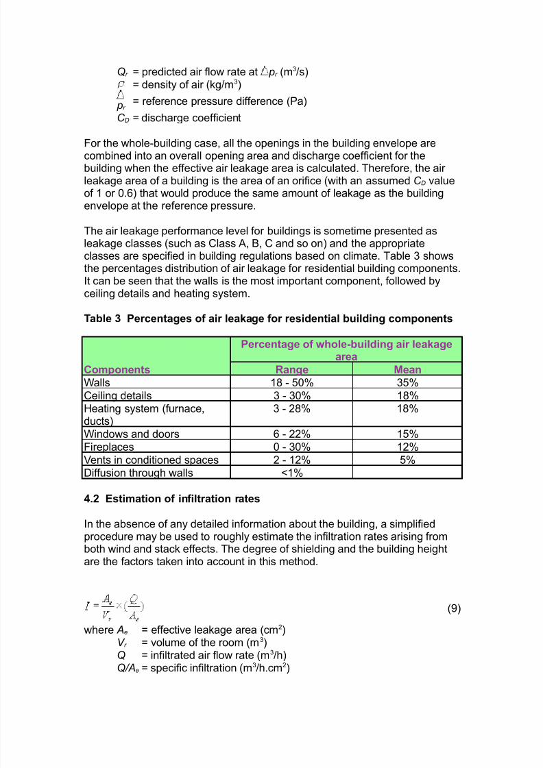
For the whole-building case, all the openings in the building envelope arecombined into an overall opening area and discharge coefficient for thebuilding when the effective air leakage area is calculated. Therefore, the air leakage area of a building is the area of an orifice (with an assumed C D valueof 1 or 0.6) that would produce the same amount of leakage as the buildingenvelope at the reference pressure. The air leakage performance level for buildings is sometime presented asleakage classes (such as Class A, B, C and so on) and the appropriateclasses are specified in building regulations based on climate. Table 3 shows
the percentages distribution of air leakage for residential building components.It can be seen that the walls is the most important component, followed byceiling details and heating system. Table 3 Percentages of air leakage for residential building components
Percentage of whole-building air leakagearea
Components Range Mean
Walls 18 - 50% 35%
Ceiling details 3 - 30% 18%Heating system (furnace,ducts)
3 - 28% 18%
Windows and doors 6 - 22% 15%Fireplaces 0 - 30% 12%
Vents in conditioned spaces 2 - 12% 5%Diffusion through walls <1% 4.2 Estimation of infiltration rates In the absence of any detailed information about the building, a simplified
procedure may be used to roughly estimate the infiltration rates arising fromboth wind and stack effects. The degree of shielding and the building heightare the factors taken into account in this method.
(9)
where Ae = effective leakage area (cm2)V r = volume of the room (m3)Q = infiltrated air flow rate (m3/h)
Q/Ae = specific infiltration (m
3
/h.cm
2
)

8/14/2019 Lecture-Air Movement+Natural Vent
http://slidepdf.com/reader/full/lecture-air-movementnatural-vent 13/15
In this equation, the specific infiltration may be calculated by:
(10)
where A = stack coefficient (m6/h2/cm4/K)B = wind coefficient (m6/h2/cm4/(m/s)2)V W = average wind speed at local weather station (m/s)
T = average indoor-outdoor temperature difference (oC)
The values of stack coefficient and wind coefficient with respect to thedifferent shielding levels are given in Table 4. Table 4 Stack coefficient and wind coefficient
Number of storeysDescription One Two Three
Stack coefficient 0.00188 0.00376 0.00564Wind coefficient - no obstruction or localshielding
0.00413 0.00544 0.00640
- light shielding, fewobstructions
0.00319 0.00421 0.00495
- moderate local shielding 0.00226 0.00299 0.00351
- heavy shielding 0.00135 0.00178 0.00209- very heavy shielding 0.00041 0.00054 0.00063
4.3 Air leakage of building component Additional test procedures for pressure-testing individual building componentsare also available. The component leakage data are useful to building designsince they could be used to determine a more accurate picture of the likely air leakage performance. Table 5 shows effective air leakage areas for somebuilding components. The values in the table give results in terms of air leakage area per unit component. Per unit component means per component,per unit surface area, or per unit length of crack or sash, whichever is
appropriate. The air leakage areas may be converted to the results at other reference pressures, air flow rates, or flow coefficients using some empiricalequations. Table 5 Effective air leakage areas of building components Building components Unit Best estimate RangeCeiling - general cm2/m2 1.8 0.79 - 2.8
- drop cm2/m2 0.19 0.046 - 0.19
- recessed lights cm2/each 10 1.5 - 21
- surface-mounted lights cm2/each 0.82 Doors

8/14/2019 Lecture-Air Movement+Natural Vent
http://slidepdf.com/reader/full/lecture-air-movementnatural-vent 14/15
- single, not weatherstripped cm2/each 21 12 - 53
- single, weatherstripped cm2/each 12 4 - 27
- double, not weatherstripped cm2/m2 11 7 - 22
- double, weatherstripped cm2/m2 8 3 - 23
- interior (stairs) cm2/lmc 0.9 0.25 - 1.5
- mail slot cm2/lmc 4 Walls (exterior) - cast-in place concrete cm2/m2 0.5 0.048 - 1.8
- clay brick cavity wall (finished) cm2/m2 0.68 0.05 - 2.3
- precast concrete panel cm2/m2 1.2 0.28 - 1.65
- low-density concrete block(unfinished)
cm2/m2 3.5 1.3 - 4
- low-density concrete block(painted)
cm2/m2 1.1 0.52 - 1.1
- high-density concrete blk.(unfinished)
cm2/m2 0.25 Windows - awning, not weatherstripped cm2/m2 1.6 0.8 - 2.4
- awning, weatherstripped cm2/m2 0.8 0.4 - 1.2- casement, not weatherstripped cm2/lmc 0.28 - casement, weatherstripped cm2/lmc 0.24 0.1 - 3
- double-hung, notweatherstripped
cm2/lmc 2.5 0.86 - 6.1
- double-hung, weatherstripped cm2/lmc 0.65 0.2 - 1.9
- single-hung, weatherstripped cm2/lms 0.87 0.62 - 1.24
- single horizontal slider,weatherstripped
cm2/lms 0.67 0.2 - 2.06
- single horizontal slider, wood cm2/lms 0.44 0.27 - 0.99
- single horizontal slider,aluminium
cm2/lms 0.8 0.27 - 2.06
- storm inside, heat shrink cm2/lms 0.018 0.009 - 0.018- window sill cm2/lmc 0.21 0.139 - 0.212
Electrical outlets/switches - no gaskets cm2/each 2.5 0.5 - 6.2
- with gaskets cm2/each 0.15 0.08 - 3.5
Piping/plumbing/wiring penetrations
- uncaulked cm2/each 6 2 - 24
- caulked cm2/each 2 1 - 2
Vents - bathroom with damper closed cm2/each 10 2.5 - 20
- bathroom with damper open cm2/each 20 6.1 - 22
Notes: 1. lmc = linear metre of crack; lms = linear metre of sash.2. Data based on a pressure difference of 4 Pa and C D = 1.3. Data source: 1997 ASHRAE Fundamental Handbook , Chp. 25.
The building envelope of large commercial buildings are often thought to bequite air tight, but in fact many cases indicate that some components and theworkmanship of them may affect the performance significantly. The infiltrationcalculations usually focus on doors and windows which are the obvious weakpoints. Lift, stair, service shaft walls; floors; and other internal partitions arealso the major separating elements of concern in these buildings. In large buildings, the air leakage associated with internal partitions is veryimportant for evaluating internal air flow. Their leakage characteristics are

8/14/2019 Lecture-Air Movement+Natural Vent
http://slidepdf.com/reader/full/lecture-air-movementnatural-vent 15/15
needed to determine infiltration through exterior walls and air flow patternswithin the building. These internal resistances are very essential for twoaspects:
in the event of a fire, to predict smoke movement patterns and determine
smoke management strategies; and to support air movement calculations when designing air distribution
systems. Further Reading
Allard, F., 1998. Natural Ventilation in Buildings: A Design Handbook ,James & James, London. [697.92 N2]
CIBSE, 1997. Natural Ventilation in Non-domestic Buildings, CIBSE Applications Manual AM10: 1997 , Chartered Institution of Building ServicesEngineers (CIBSE), London. [LB 697.92 N28]
Clements-Croome, D. (ed.), 1997. Naturally Ventilated Buildings: Buildingsfor the Senses, Economy and Society , E & FN Spon, London. [697.92 N1]
DETR, 1998. Natural Ventilation in Non-domestic Buildings: A Guide for Designers, Developers, and Owners, Good Practice Guide 237, Dept. of theEnvironment, Transport and Regions (DETR), Garston, Watford. [P 697.92 N2v]
Jackman, P. J., 1999. Air Distribution in Naturally Ventilated Offices,Technical Note TN 4/99, Building Services Research and InformationAssociation, Bracknell, England. [P 697.93523 J12]
Martin, A. J., 1996. Control of Natural Ventilation, Technical Note TN 11/95,Building Services Research and Information Association, Berkshire, England.
[LB 697.92 M37]