Embed Size (px)
Citation preview

Variations in form and stress behaviour of a V-shaped membrane in a foldable structure
M. Mollaert, N. De Temmerman & T. Van Mele Department of Architecture, Vrije Universiteit Brussel, Belgium
Abstract
Adaptable tensile structures are often considered to be either completely opened or completely closed. The current study is part of a research project studying adaptable tensile structures which demonstrate stable behaviour within a wide range of opened positions. In this paper a simple V-shaped membrane is studied during the unfolding process. Starting from an initially flat folded membrane, which is not pre-tensioned, a slight curvature is obtained when it is unfolded due to the fact that along the folding line a curved section is cut out of the fabric. The tension introduced in the transverse direction implies a tension in the longitudinal direction too. Two cases are analysed: one with a high curvature in the diagonal cable (~5% sag) and one with a low curvature (~1.3% sag). Based on computer simulations the form and the tensions are verified for different opening angles. The deformation under loading is checked for the shape with a low curvature of the diagonal cable at an opening angle of 70º. The results indicate that the membrane could be used as a fabric roof. Further refined analysis is needed to be able to implement the presented concept for real applications. Keywords: tensile structure, formfinding, coated textiles, adaptable shelter, foldable structures.
1 Introduction
adaptable buildings that can react (open/close) to changing environmental conditions [1].
tensioned while folding or unfolding. A first possibility is to start from a wave
High Performance Structures and Materials III 41
Tension structures, made of high-strength coated fabrics, are well-suited to create
Several solutions are possible, but only a few techniques keep the membrane
doi:10.2495/HPSM06005
© 2006 WIT PressWIT Transactions on The Built Environment, Vol 85, www.witpress.com, ISSN 1743-3509 (on-line)

form. The chosen reference equilibrium form is characterised by an intermediate opening angle (Fig. 5) and an appropriate pre-tension. When the wave form opens (Fig. 6) or closes (Fig. 4), the membrane tension does not change too much as long as the variation in the curvature is not too important and the membrane can be used as a roof in the intermediate positions [2, 3].
Figure 1: Parallel sliding.
Figure 2: Central sliding.
Figure 3: Circular sliding.
Figure 4: Folded configuration.
Figure 5: Reference configuration.
Figure 6: Unfolded configuration.
Figure 7: Folded rhombus shape.
Figure 8: Opened rhombus shape.
Figure 9: Curved diagonal.
In the current study the reference equilibrium form is a folded configuration without pre-tension. To test the basic idea a small model of a rhombus shape with straight edges and covered by fabric was made (Fig. 7, Fig. 8 and Fig. 9). The longitudinal diagonal divides the rhombus in two isosceles triangles with an apex angle of 120º (see Fig. 13 for the definition of the angle). The longitudinal diagonal is the folding axis. At this folding axis a part of the fabric was cut out along an arc that represents the cutting line. As a consequence the longitudinal diagonal is slightly curved. During the unfolding process the membrane is
42 High Performance Structures and Materials III
© 2006 WIT PressWIT Transactions on The Built Environment, Vol 85, www.witpress.com, ISSN 1743-3509 (on-line)

tensioned in the transverse direction, and due to the bi-axial behaviour of the material, the longitudinal direction is tensioned too. The opening angles ranging from 60º to 80º are the most appropriate (in terms of covered area: see Fig. 11, Fig. 12) if one wants to use the unfolded tensioned membrane as an architectural roof.
Figure 10: Elevation for
opening angles ranging from 50º to 90º.
Figure 11: Covered
opening 70º.
Figure 12: Covered areafor an openingangle of 80º.
The cladding material is a coated fabric and the longitudinal diagonal is reinforced by a belt or a cable. The membrane itself is modelled by a mesh of 25cm x 25cm. The boundaries are considered to be stiff beams and modelled as fixed points on the boundary lines. Starting from a tensionless folded state, called the reference equilibrium form, the stress behaviour is analysed, while unfolded along the longitudinal diagonal.
2 Defining the reference equilibrium form
The reference equilibrium form is characterised by an opening angle of 1º and an initial tension in the membrane of 0.02kN/m, considered as a tensionless state. Calculations are made with the EASY software of Technet, based on the Force Density Method [4]. The formfinding based on the force-density method calculates an equilibrium form that is independent of the stiffness of the elements in the net. Different force values in the diagonal cable can be considered. The force values depend on the ratio of the force-density set for the longitudinal cable to the force-density set for the internal net. Five cases have been calculated to be able to estimate the curvature of the diagonal cable for different values of the force in the diagonal cable. The curvature is characterised by the ratio of the height H divided by the span S (see Fig. 13), the span being 6m. For the numeric modelling a rhombus of 6.0m x 3.464m is considered. The following figure illustrates the geometry and basic parameters: For two cases the unfolding has been analysed:
Case 1, having a higher curvature in the diagonal cable, will be considered with a low stiffness of 1kN of the internal net elements, which represents the situation of a ‘stretchable’ net
Case 5, having a lower curvature in the diagonal cable, will be considered with a more realistic stiffness of 150kN of the internal net elements, both in the longitudinal and in the transverse direction
High Performance Structures and Materials III 43
angle of
area for an
© 2006 WIT PressWIT Transactions on The Built Environment, Vol 85, www.witpress.com, ISSN 1743-3509 (on-line)

Used symbols β apex angle of
triangular module
θ opening angle of triangular module
H height of the longitudinal arc
arc AA’ arc in longitudinal direction (along X-axis)
arc BB’ arc in transversal direction (along Y-axis)
Figure 13: Geometry and used symbols. S = AA’
span of the longitudinal arc
Table 1: The height to span ratio of the diagonal for different forces in the diagonal cable.
Case Elevation Force [kN]
Height [m]
H/S [%]
5
2.1453
0.0775
1.29
4 1.7173 0.0952 1.59
3 1.2895 0.1233 2.06
2 0.8622 0.1750 2.92
1
0.4359
0.3013
5.02
44 High Performance Structures and Materials III
© 2006 WIT PressWIT Transactions on The Built Environment, Vol 85, www.witpress.com, ISSN 1743-3509 (on-line)

0.00
0.50
1.00
1.50
2.00
2.50
1.29 1.59 2.06 2.92 5.02
H/S of the diagonal arch [%]
Forc
e [k
N]
Figure 14: Force in the diagonal cable (at 1º opening angle).
It is obvious that the smaller the force in the diagonal cable, the greater the curvature of the diagonal arc will be (for the same pretension in the membrane of 0.02kN/m). But on the other hand, the greater the curvature of the diagonal cable, the higher the stresses in the transverse direction will be when unfolding.
3 Tension in the membrane for different opening angles
3.1 Case 1: Higher curvature in the diagonal cable
The influence of the opening angle on the forces in the membrane and the diagonal cable is verified for a low stiffness of the internal net (1kN) and a stiffness of 5000kN of the diagonal cable. The first form given in Table 2 is the reference equilibrium form (with an opening angle of 1º). The other configurations have been obtained by a static analysis, starting from the reference equilibrium form, with the fixed nodes displaced according to the considered opening angle.
0.00
0.10
0.20
0.30
0.40
0.50
10 20 30 40 50 60 70 80
Opening angle [º]
Tens
ion
[kN
/m]
Figure 15: Tension in the transverse direction due to variation of the opening
angle.
From the calculations with a stiffness of 1kN in the internal net it can be concluded that
- in the longitudinal direction the tension in the membrane remains at a value of about 0.02kN/m
- in the direction perpendicular to the folding axis the tension increases from 0.02kN/m to 0.44kN/m for larger opening angles.
High Performance Structures and Materials III 45
© 2006 WIT PressWIT Transactions on The Built Environment, Vol 85, www.witpress.com, ISSN 1743-3509 (on-line)

0.00
1.00
2.00
3.00
4.00
5.00
6.00
10 20 30 40 50 60 70 80
Opening angle [º]
Forc
e [k
N]
2.70
2.80
2.90
3.00
3.10
3.20
3.30
3.40
10 20 30 40 50 60 70 80
Opening angle [º]
H/S
[%]
cable due to variation of the opening angle.
H/S of the diagonal cabledue to variation of theopening angle.
When unfolding, the force in the diagonal cable increases up to a maximum value. Then the force in the diagonal cable decreases for larger opening angles. Since the force in the cable is proportional to the resultant of the membrane tension at both sides of the cable, two different facts interact:
- for larger opening angles the resultant decreases if the tension in the membrane remains the same
- for larger opening angles the membrane tension in the transverse direction increases
with lower membrane tensions at 60º.
A lower resultant forcewith higher membranetensions at 70º
3.2 Case 5: Lower curvature in the diagonal cable
The influence of the opening angle on the stresses in the membrane and the diagonal cable is verified for a more realistic stiffness in the internal net of 150kN. The stiffness for the diagonal cable remains 5000kN. The 150kN per 0.25m corresponds to a value of 600kN/m valid for a typical PVC coated polyester membrane. From the calculations where the opening angle varies between 60º and 80º can be concluded that:
- in the longitudinal direction the tension in the membrane varies from a value of about 0.6kN/m up to 2.2kN/m for larger opening angles
- in the direction perpendicular to the folding axis the tension increases from 0.4kN/m to 20.0kN/m for larger opening angles
Similar to the membrane tensions in the longitudinal direction, the forces in the diagonal cable increase up to a maximum value and then decrease due to variation of the opening angle.
46 High Performance Structures and Materials III
Figure 16: Force in the diagonal Figure 17:
Figure 18: A higher resultant force Figure 19:
© 2006 WIT PressWIT Transactions on The Built Environment, Vol 85, www.witpress.com, ISSN 1743-3509 (on-line)
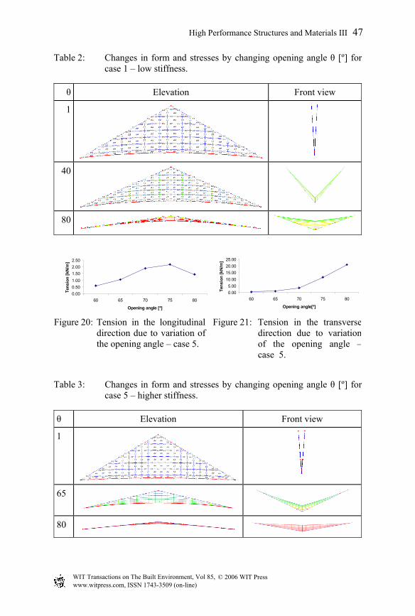
Table 2: Changes in form and stresses by changing opening angle θ [º] for case 1 – low stiffness.
θ Elevation Front view
1
40
80
0.000.501.001.502.002.50
60 65 70 75 80
Opening angle [º]
Tens
ion
[kN
/m]
0.005.00
10.0015.0020.0025.00
60 65 70 75 80
Opening angle[º]
Tens
ion
[kN
/m]
Figure 20: Tension in the longitudinal direction due to variation of the opening angle – case 5.
Figure 21: Tension in the transversedirection due to variationof the opening angle –case 5.
Table 3: Changes in form and stresses by changing opening angle θ [º] for case 5 – higher stiffness.
θ Elevation Front view
1
65
80
High Performance Structures and Materials III 47
© 2006 WIT PressWIT Transactions on The Built Environment, Vol 85, www.witpress.com, ISSN 1743-3509 (on-line)

0.005.00
10.0015.0020.0025.0030.00
60 65 70 75 80
Opening angle [º]
Forc
e [k
N]
0.001.002.003.004.005.00
60 65 70 75 80
Opening angle [º]
H/S
[%]
Figure 22: Force in the diagonal cable due to variation of the opening angle – case 5.
Figure 23: H/S of the diagonal cabledue to variation of theopening angle – case 5.
Plan and Elevation Front view
Figure 24: Equilibrium form at an opening angle of 70º.
Plan 3D-view with loading
Elevation Front view
Figure 25: Structure under snow load (0.4kN/m2).
4 Tension in the membrane at an opening angle of 70º under external loading
Still for case 5, with a stiffness of 150kN in the internal net and 5000kN in the diagonal cable, external loading will be applied for an opening angle of 70º. Two representative load cases have been chosen [5]: a uniform snow load of 0.4kN/m2 and an upward wind load of 0.6kN/m2. For the equilibrium form with an opening angle of 70º without external loading the average tension in the membrane is 2kN/m in the longitudinal direction and 4kN/m in the transverse
48 High Performance Structures and Materials III
© 2006 WIT PressWIT Transactions on The Built Environment, Vol 85, www.witpress.com, ISSN 1743-3509 (on-line)

direction. The static analysis under external loading combines the displacement of the fixed nodes according to the opening angle of 70º with the application of load vectors for the selected load case on the equilibrium form without external loading. A uniform snow load of 0.4kN/m2 has been applied. In this case the maximum deflection is 2cm. In the transverse (load bearing) direction the average tension increases from 4 up to 5kN/m. Next an upward wind load of 0.6kN/m2 (suction) has been applied. In this case a maximum deflection of 4cm occurs. In the longitudinal direction the average tension increases from 2 up to 3.1kN/m.
Plan 3D-view with loading
Elevation Front view
Figure 26: Structure under upward wind load (0.6kN/m2).
5 General remarks
The simulations only give a first estimation of the structural behaviour: the model does not take into account the shear stiffness of the coated fabric, the material behaviour is considered to be linear and independent of the stress level and frequently folding and unfolding will also influence the material behaviour. For more precise results a refined model is required. Moreover, an optimised configuration could be found by choosing a different stiffness or selecting another boundary geometry in plan view.
6 Conclusion
For the same external loading on a membrane roof a more expressive double curvature will imply lower tensions in the membrane. Nevertheless more and more applications use a ‘flat appearing’ curvature to cover box-like spaces. The rhombus-shaped membrane elements will be used as cladding components in a mobile foldable shelter consisting of articulated bars as the primary load bearing structure [6]. Based on the simulation of a rhombus shaped membrane it is shown that the unfolding of flat membrane pieces can, within a certain range of opening angles, create a slightly curved tensioned membrane which can resist, in
High Performance Structures and Materials III 49
© 2006 WIT PressWIT Transactions on The Built Environment, Vol 85, www.witpress.com, ISSN 1743-3509 (on-line)

an acceptable way, representative external wind and snow loads. Several parameters should still be optimised (size, geometry, stiffness) for a specific application of the V-shaped foldable membrane.
References
[1] F. Otto, B. Baier and S. Meyer-Miethke, IL 14 Adaptable Architecture, Karl Krämer Verlag, Stuttgart (1975).
[2] M. Mollaert, N. De Temmerman, T. Van Mele, Ph. Block Philippe, F. Daerden, Adaptable Tensioned Coverings, Proceedings of the IASS-APCS International Symposium on New Perspectives for Shell and Spatial Structures, Taipei, Taiwan pp.204-205, (full paper on cd-rom) (2003).
[3] M. Mollaert, T. Van Mele, N. De Temmerman, Kinetic Structures: Architectural Organisms as a Design Concept, Proceedings IASS Symposium Shell and Spatial Structures from Models to Realization, Montpellier, p.410, (full paper on cd-rom) (2004).
[4] E. Moncrieff, Extreme Patterning: Lessons From the Cutting Pattern Generation of the Mina Valley Tent City and the Federal Chancellery Projects, TensiNet Symposium: Designing Tensile Architecture, pp.66-81, Brussels (2003).
[5] B. Forster, M. Mollaert, European Design Guide for Tensile Surface Structures, TensiNet (2004).
[6] De Temmerman, N., Mollaert, M., Decorte, W., Parametrization and development of a foldable mobile shelter system, Vrije Universiteit Brussel, Research Working Paper No. 2, (2005).
50 High Performance Structures and Materials III
© 2006 WIT PressWIT Transactions on The Built Environment, Vol 85, www.witpress.com, ISSN 1743-3509 (on-line)