Embed Size (px)
Citation preview

Tensile Surface Structures Introduction to the Eurocode framework
TU1303 WG521-09-2017
Marijke MollaertJean-Christophe Thomas 1
1
COST Action TU1303
Novel Structural SkinsImproving sustainability and efficiency through
new structural textile materials and designs
WG5 from material to structure and limit states:
codes and standardization
Introduction to the Eurocode framework
Jean-Christophe THOMAS, Marijke MOLLAERT
2
Introduction
Design and analysis of membrane structures with double curvature and prestress
3
Understanding the structural behaviour
is crucial
Example
André Paduart did in 1958 a hand calculation
for the design of a steel cable net
to cover a band stand at EXPO ’58 (Brussels)
Introduction
4
Introduction
Longitudinal hanging cables + transverse arching cables
5
Introduction
Longitudinal hanging cables + transverse arching cables
Pretension = action of the hanging cables on the arching cables and vice versa
Pretension vertical (re)action of 25kg/m2
6
Report
19 hand written pages
Calculations in plane
Expressing equilibrium of forces
In graphic statics
Easy to reproduce
Introduction

Tensile Surface Structures Introduction to the Eurocode framework
TU1303 WG521-09-2017
Marijke MollaertJean-Christophe Thomas 2
7
Introduction
Load cases are simplified :
a. Self-weight of the construction: 6kg/m2
b. Wind: 50kg/m2 (uniform upward, vertical); for the transversal wind: 45kg/m2
c. Accidental loading: 10kg/m2 (downward)
Self-weight combined with the distributed loads representing the pretension (25kg/m2):
a. Load on the longitudinal cables: 25kg/m2 + 3kg/m2 = 28kg/m2
b. Load on the transversal cables: 25kg/m2 - 3kg/m2 = 22kg/m2
The maximal vertical loading per cable direction:
a. Load on the longitudinal cables: -28kg/m2 - 5kg/m2 (accidental) = -33kg/m2 [~-0.33kN/m2]
b. Load on the transversal cables: 22kg/m2 + 25kg/m2 (wind) = 47kg/m2 [~0.47kN/m2]
8
Introduction
ULS:
The resistance (design value) according to the Eurocode has the same value as considered by A. Paduart, but he applied a safety coefficient of 2.5
The wind loading according to the Eurocode (rough approximation of the shape, pressure coefficients 1.8, multiplied with a partial factor of 1.5) is higher than in the calculation of A. Paduart
9
Introduction
SLS:
The wind loading is not increased with a factor 1.5
Displacements were not checked by A. Paduart
10
Introduction
The approximations
and assumptions made by A. Paduart
are well founded
and resulted in a coherent evaluation
of the cable net structure
11
Introduction
The built design was only based
on a symmetric uplift wind loading
Safe?
The structure did withstand a storm wind
In case the analysis takes into account
different wind directions
the construction
will probably become heavier
12
Since a long time the idea exists to create a commonly agreed design code for membrane structures
The design guide of the European project TensiNet was a first step in this direction
The birth of a Eurocode

Tensile Surface Structures Introduction to the Eurocode framework
TU1303 WG521-09-2017
Marijke MollaertJean-Christophe Thomas 3
13
‘The experts in the field are able to design projects without a Eurocode, why should we have to work on a standard?
There are as many different opinions and reasons as there are designers
A common reason is to increase the market and to have the technology seen as an established building technologyand not only as a niche market with high risks
The birth of a Eurocode
14
The birth of a Eurocode
With harmonised safety levels, and commonly agreed quality standards, the quality of the industry will improve…Membranes are often seen as cladding, treated as a pure add-on, neglecting an impact that might be beneficial or unfavourable
15
The birth of a Eurocode
The structure of the Allianz Arena for example has been designed without taking into account the cladding, only it‘s self weight was consideredTherefore another 50% of steel was required to do the secondary structure
With an integrated design only half of this would have been required
16
The birth of a Eurocode
Also the Unilever façade has been treated as a simple façade
Therefore it was necessary to buildstiff and heavy steel frames tocouple the high tensile forceswhich could not be taken by theconcrete building
17
The proof engineer of the Dresden Castle ETFE roof answered
I do not check the roof tiles
when he received the analysis of the cushions on the roof
The birth of a Eurocode
18
Integrated design is elementary for membrane structures, and without, membrane structures will never become economic
The standardisation process can ensure that in future others treat membrane structures with the required seriousness to the benefit of all’
Bernd Stimpfle, form-TL
The birth of a Eurocode
Tensile Surface Structures Introduction to the Eurocode framework
TU1303 WG521-09-2017
Marijke MollaertJean-Christophe Thomas 4
19
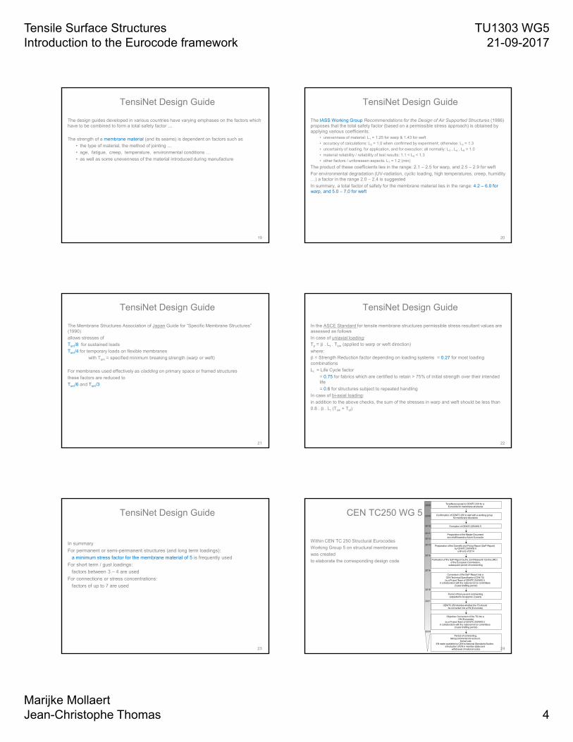
TensiNet Design Guide
The design guides developed in various countries have varying emphases on the factors which have to be combined to form a total safety factor …
The strength of a membrane material (and its seams) is dependent on factors such as
• the type of material, the method of jointing …
• age, fatigue, creep, temperature, environmental conditions …
• as well as some unevenness of the material introduced during manufacture
20
TensiNet Design Guide
The IASS Working Group Recommendations for the Design of Air Supported Structures (1986) proposes that the total safety factor (based on a permissible stress approach) is obtained by applying various coefficients:
• unevenness of material: L1 = 1.25 for warp & 1.43 for weft
• accuracy of calculations: L2 = 1.0 when confirmed by experiment; otherwise: L2 = 1.3
• uncertainty of loading, for application, and for execution: all normally: L3 , L4 , L6 = 1.0
• material reliability / reliability of test results: 1.1 < L5 < 1.3
• other factors / unforeseen aspects: L7 = 1.2 (min)
The product of these coefficients lies in the range: 2.1 – 2.5 for warp, and 2.5 – 2.9 for weft
For environmental degradation (UV-radiation, cyclic loading, high temperatures, creep, humidity …) a factor in the range 2.0 – 2.4 is suggested
In summary, a total factor of safety for the membrane material lies in the range: 4.2 – 6.0 for warp, and 5.0 – 7.0 for weft
21
TensiNet Design Guide
The Membrane Structures Association of Japan Guide for “Specific Membrane Structures” (1990)
allows stresses of
Tsm/8 for sustained loads
Tsm/4 for temporary loads on flexible membranes
with Tsm = specified minimum breaking strength (warp or weft)
For membranes used effectively as cladding on primary space or framed structures
these factors are reduced to
Tsm/6 and Tsm/3
22
TensiNet Design Guide
In the ASCE Standard for tensile membrane structures permissible stress resultant values are assessed as follows
In case of uniaxial loading:Tp = . Lt . Tsm (applied to warp or weft direction)
where: = Strength Reduction factor depending on loading systems = 0.27 for most loading combinations
Lt = Life Cycle factor
= 0.75 for fabrics which are certified to retain > 75% of initial strength over their intended life
= 0.6 for structures subject to repeated handling
In case of bi-axial loading:
in addition to the above checks, the sum of the stresses in warp and weft should be less than0.8 . . Lt (Tsw + Tsf)
23
TensiNet Design Guide
In summary
For permanent or semi-permanent structures (and long term loadings):
a minimum stress factor for the membrane material of 5 is frequently used
For short term / gust loadings:
factors between 3 – 4 are used
For connections or stress concentrations:
factors of up to 7 are used
24
CEN TC250 WG 5
Within CEN TC 250 Structural Eurocodes
Working Group 5 on structural membranes
was created
to elaborate the corresponding design code
Preparation of the Scientific and Policy Report (SaP-Report) by CEN/TC 250/WG 5
until end of 2014
Preparation of the Master Documentas a draft towards a future Eurocode
Formation of CEN/TC 250/WG 5
Confirmation of CEN/TC 250 to start with a working groupfor membrane structures
TensiNet proposal to CEN/TC 250 for aEurocode for membrane structures
Publication of the SaP-Report by the Joint Research Centre (JRC) of the European Commission,
subsequent period of commenting
Conversion of the SaP-Report into a CEN Technical Specification (CEN TS)
by a Project Team of CEN/TC 250/WG 5 in collaboration with the national mirror committees
(3 year drafting period)
Period of trial use and commenting (expected to be approx. 2 years)
CEN/TC 250 decides whether the TS should be converted into a EN (Eurocode)
Objective: Conversion of the TS into a EN (Eurocode)
by a Project Team of CEN/TC 250/WG 5 in collaboration with the national mirror committees
(3 year drafting period)
Period of commenting,taking comments into account,
formal vote,EN made available by CEN to National Standards Bodies,
introduction of EN in member states and withdrawal of national codes
2013
2010
2009
2008
2011-
2013
2015
2016
2019
2021
2024
Tensile Surface Structures Introduction to the Eurocode framework
TU1303 WG521-09-2017
Marijke MollaertJean-Christophe Thomas 5
25
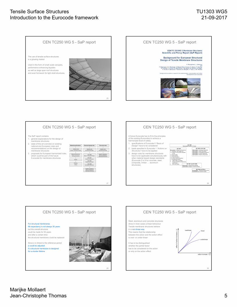
CEN TC250 WG 5 - SaP report
The use of tensile surface structures
is a growing market
Used in the form of small scale canopies,
performance enhancing façades
as well as large span roof structures
and even formwork for light shell structures
26
CEN TC250 WG 5 - SaP report
27
CEN TC250 WG 5 - SaP report
The SaP report contains
1. general explanations for the design of membrane structures
2. state-of-the-art overview on existing national and European rules and recommendations on the design of membrane structures
3. proposals for European harmonized rules, which could be part of the future Eurocode for membrane structures
Material specifications Structural design rules Execution rules
Material standards
Testing standards
CEN/TC 248 Textiles and textile products
EOTA
ETAG‘s
ETA‘s
CEN/TC 250Structural Eurocodes
CEN/TC 250Structural Eurocodes
EN 1990Basis of Structural Design
EN 1991Actions on Structures
CEN/TC 250/WG 5 Structural Design of
Membrane Structures
CEN/TC 250/WG 5 Structural Design of
Membrane Structures
EN 1997Geotechnical Design
EN 1998Earthquake Resistance
28
CEN TC250 WG 5 - SaP report
A future Eurocode has to fit to the principles of the existing Eurocodes to achieve a harmonized level of safety
1. specifications of Eurocode 0 “Basis of Design” have to be considered
2. loads specified in Eurocode 1 “Actions on Structures” have to be applied
3. design rules for membrane structures have to be applicable simultaneously with other material based design standards (Eurocode 2 to 9 for concrete, steel, composite, timber … aluminum structures)
EN 1990Eurocode 0: Basis of Design
EN 1991Eurocode 1: Actions on Structures1-1 Densities, self-weight etc.1-2 Actions on structures exposed to fire1-3 Snow loads1-4 Wind actions1-5 Thermal actions1-6 Actions during execution1-7 Accidential actions2 Traffic loads on bridges3 Actions induced by cranes and machinerys4 Silos and tanks
EN 1992 to EN 1996
Eurocode 2: Concrete StructuresEurocode 3: Steel StructuresEurocode 4: Composite StructuresEurocode 5: Timber StructuresEurocode 6: Masonry Structures
EN 1997 and EN 1998
Eurocode 7: Geotechnical DesignEurocode 8: Design in Seismic Areas
EN 1999 and EN xyEurocode 9: Aluminium StructuresEurocode xy: Structural Glass
29
CEN TC250 WG 5 - SaP report
For structural membranes
life expectancy is not always 50 years
but the overall structure
could be made for 50 years
and after a certain time
the structural membrane could be replaced
Since is linked to the reference period
could be adjusted
if a structural membrane is designed
for a shorter lifetime
30
CEN TC250 WG 5 - SaP report
Steel, aluminium and concrete structures
show in most cases a linear behaviour
Tensile membrane structures behave
in a non-linear way
This means that the relationship
between the action and the action effect
is over- or under-linear
It has to be distinguished
whether the partial factor
has to be considered on the action
or only on the action effect
action increase [-]f
effe
ct o
f act
ion
incr
ease
[-
] linear
underlinear
overlinear

Tensile Surface Structures Introduction to the Eurocode framework
TU1303 WG521-09-2017
Marijke MollaertJean-Christophe Thomas 6
31
CEN TC250 WG 5 - SaP report
Factors are specified to take into account a strength reduction due to
kage: environmental impacts (pollution, UV-rays, rain… )
kbiax: a biaxial stress state
kong: the effect of long term loads
ktemp: the effect of elevated temperature
ksize: the size of membrane panels
32
CEN TC250 WG 5 - SaP report
The design tensile strength of the membrane material or the joint is given byfd = fk,23 / (gM.· { kage; kbiax; klong; ktemp; ksize; kx}) with ki ≥ 1.0
33Reference: lectures from Jean-Armand Calgaro and others at
http://www.novelstructuralskins.eu/events/training-schools/
EUROCODE
34
EUROCODE
1989: agreement for a mandate for 20 years
Responsible for the development: CEN TC 250
First Eurocodes established
2010: withdrawal of contradictory national standards
2012: New mandate:
Maintenance
Harmonisation
Develop new parts, like for membrane structures
Reference: EN-1990 Eurocode - Basis of structural design
35
EUROCODE
36
EUROCODE

Tensile Surface Structures Introduction to the Eurocode framework
TU1303 WG521-09-2017
Marijke MollaertJean-Christophe Thomas 7
37
EUROCODE
38
EUROCODE
The probabilistic approach of structural safety:
Identify limit states
Evaluate the risks
Design in such a way that the probability of the mentioned risks is low
39
EUROCODE
Semi-probabilistic verification:
Adopt representative values for actions, resistances…
Apply partial factors g to actions, resistances…
Introduce safety margins in the models of actions, action effects…
40
Material property Xk
Design valueXd = (h/gm).Xk
Design value of geometric data ad
Resistances
R(Xd,ad)
Design value of resistancesRd = (1/gRd).R(Xd,ad)
Rd = (1/gM).Rk
EUROCODE
Actions Fk
Design valueFd = gf .Fk
Design value of geometric data ad
Effects of actions
E(Fd,ad)
Design value of effects of actions Ed = gEd.E(Fd,ad)
Ed = gF.Ek
41
Verification SLS
Ed < Cd
Cd limiting design value for the serviceabilitycriterion
EUROCODE
Verification ULS
Ed < Rd
Rd design value for the correspondent resistance
Specific combinations of actions
Recommended values for the partial factors g
42
EUROCODE
Level II procedure
The reliability is defined by the reliability index b
Pf = probability of failurePf = F(-b)

Tensile Surface Structures Introduction to the Eurocode framework
TU1303 WG521-09-2017
Marijke MollaertJean-Christophe Thomas 8
43
EUROCODE
44
EUROCODE
EN 1990 specifies failure consequences for ULS and SLS
Considering normal failure consequences
with reliability class 2
and a 50 year re-occurrence
the failure probability pf ranges
from 10-2 in SLS
up to 710-5 in ULS in which case the reliability index = 3.8
45
The target value b50 = 3.8
corresponds to
the ‘acceptable’ probability of failure Pf 50 = 7.2 10-5
The b-value is a formal number
to develop consistent design rules
It does not give a real indication
of the structural failure frequency
EUROCODE
46
EUROCODE
47
EUROCODE
48
EUROCODE
E and R are independently Normally distributed with parameters (mE, sE) and (mR, sR)
For a reliable design Z = (Rd - Ed) > 0
Z also follows a Normal distributionThe reliability index b=mZ/sZ
The target reliability index is b0
For a reliable design b>b0

Tensile Surface Structures Introduction to the Eurocode framework
TU1303 WG521-09-2017
Marijke MollaertJean-Christophe Thomas 9
49
EUROCODE
50
EUROCODE
51
The partial safety factors are function of the target reliability index b (design point)
Verification with the partial factorsgF.Ek < (1/gM).Rk
OrgF.gM< gk
EUROCODE
52
EUROCODE
53
Final remarks
Remaining questions
- In Eurocode 0 a reliability index β of 3.8 is specified for a complete structure. Is considering k-factors a compatible approach?
- Values for SLS and ULS are agreed upon by experts, is the current approach conservative?
- Reduction factors are multiplied. Are they independent?
- Different partial material factors for material and connections?
- …
54
Final remarks
A good reference for reliability concepts in the ECs in the following publication
http://eurocodes.jrc.ec.europa.eu/showpublication.php?id=63

Tensile Surface Structures Introduction to the Eurocode framework
TU1303 WG521-09-2017
Marijke MollaertJean-Christophe Thomas 10
55
Final remarks
‘Eurocodes can also be used for the analysis and design of unconventional structures’
Johannes Berger