Embed Size (px)
Citation preview

VÅNTEC-500 Area Detector for Pharmaceutical XRDPharmaceutical XRD
18.05.2011Bruker Confidential
Bob He 1

This document was presented at PPXRD -Pharmaceutical Powder X-ray Diffraction Symposium
Sponsored by The International Centre for Diffraction Data
This presentation is provided by the International Centre for Diffraction Data in cooperation with the authors and presenters of the PPXRD symposia for the express purpose of educating the scientific community.
All copyrights for the presentation are retained by the original authors.
The ICDD has received permission from the authors to post this material on our website and make the material available for viewing. Usage is restricted for the purposes of education and scientific research.
ICDD Website - www.icdd.comPPXRD Website – www.icdd.com/ppxrd

XRD2 for Pharmaceutical:Reflection System (CS)Reflection System (CS)
18.05.2011Bruker Confidential2

XRD2 for Pharmaceutical:Reflection & Transmission (HTS)Reflection & Transmission (HTS)
Reflection Transmission convertible Geometry
US Patent #7 242 745
18.05.2011Bruker Confidential3
#7,242,745

XRD2 : Innovation and Development
The most dramatic development in XRD2 happens in three critical components and data evaluation
p
in three critical components and data evaluation algorithms:Source: required radiation energy, focal spot size and intensity.Optics: select wavelength, beam profile and divergencedivergence.Detector: collect 2D pattern with correct intensity and position.Data evaluation Algorithm: Diffraction Vector Approach.
Bruker Confidential4

X-ray Source for XRD2:Incoatec Microsource (IμS)TM Incoatec Microsource (IμS)TM
High brillianceLo ene g 30 WLow energy: 30 WAir-cooledSpot size < 100 µmSpot size < 100 µmMontel mirrow
18.05.2011Bruker Confidential5

IμS & VÅNTEC-2000 vs. Classic Set-upCorundum ComparisonCorundum Comparison
IμS & VÅNTEC-2000IμS & VÅNTEC 2000
45kV, 0.650mA,
0.3mm snout
total counts: 1235K
Single 40mm Göbel Mirror,
45kV 40 A45kV, 40mA,
0.3mm collimator
total counts: 78K
18.05.2011Bruker Confidential6

XRD2: Choice of DetectorsSensitivity vs Count Rate Sensitivity vs. Count Rate
Detective Quantum Efficiency (DQE):
MiKroGapMWPC
CCD
y ( )The DQE is a parameter
defined as the square of the ratio of the output and input signal-to-nose ratios p g(SNR).
2
)/()/(
⎟⎟⎠
⎞⎜⎜⎝
⎛=
in
out
NSNSDQE
Image Plate The DQE of a real detector is less than 100% because not every incident x-ray photon is detected,
⎠⎝ in
and because there is always some detector noise.
MiKroGap™ has the best
7
overall performance.

Detector Technology from MWPC to -MikroGapTMMikroGap
MikroGapTM technology with MWPC
resistive anode: shortens drift time of ionsf l dfast electrons induce charge on readout strips
Adjusted surface resistance (105 - 107 Ω/ area): MikroGapTM(105 - 10 Ω/ area):
high enough to limit dischargeslow enough to support
MikroGap
low enough to support high count rates
US P t t US 6 340 819 B1
Bruker Confidential8
US Patent US 6,340,819 B1

VÅNTEC-500 – Outperforms all previous gaseous detectorsprevious gaseous detectors
Similar to Hi-Star (MWPC) detector:High sensitivity: 80% DQE (detection High sensitivity: 80% DQE (detection quantum efficiency) at 8.04 keVradiationEnergy range: 3-15 keV (good for Cu, gy g (g ,Co, Fe and Cr X-ray sources, not recommended for Mo)Energy resolution (∆E/E): 20% at 8.04 keV radiationkeV radiationLow background noise: <5 cps/global Readout time: real timeN liNo coolingCurved Be-window to reduce parallax
9

VÅNTEC-500 – Outperforms all previous gaseous detectorsprevious gaseous detectors
Advances from MWPC:Tapered front end for high 2θ angle Tapered front end for high 2θ angle access and space for large samples and sample stagesDoubled the spatial resolution: The pFWHM of the PSF is 200μmTwo orders of magnitude higher maximum count rate:Global co nt ate 1 5McpsGlobal count rate: 1.5McpsLocal count rate: 250kcps per point-like reflection Radiation hardness: accidental Radiation hardness: accidental intensive irradiation without permanent damageMaintenance-free: no re-gassing
10
g g

VÅNTEC-500 – Tapered front for low and high 2θ accessibility for low and high 2θ accessibility
larctan22 =θDrange arctan22 =θ
hm +D
hm +−= πθmax2
11

VÅNTEC-500 – Outperforms all previous gaseous detectorsprevious gaseous detectors
Detector geometry:Be-window opening 140 mm in dia.Frame size: 2048 x 2048 pixels1024 x 1024 pixels512 x 512 pixelsPixel size: Pixel size: 68 μm x 68 µm 136 μm x 136 µm272 μm x 272 µmDetector working distance: Detector working distance: 5~30 cm in D8 DISCOVER enclosure
2θ range in a single frame:5 cm 83°10 cm 56°10 cm 56°15 cm 42°20 cm 33°25 cm 27°30 23
12
30 cm 23°

Hi-resolution with MikroGapTM Technology
272 μm pixel (512x512) 136 μm pixel (1024x1024) 68 μm pixel (2048x2048)
68 μm pixel size delivers the best spatial resolution

The New D8 DISCOVER
Bruker Confidential14

The New D8 DISCOVERThe New D8 DISCOVERPatented Door Mechanism
Swing door: wide Sliding door: easy accessSwing door: wide opening for good
accessibility
Sliding door: easy access for sample loading and configuration changes
March 16, 2010Bruker Confidential15

The D8 DISCOVER with DAVINCI TWIST-TUBE – from line to spot, and backTWIST TUBE from line to spot, and back
Fast and easy switching between line and spot focusFocus direction recognitionFocus direction recognitionNo need to disconnect cablesC tibl ith t d d Compatible with standard tube designBruker AXS proprietary technology
Bruker Confidential16

The D8 DISCOVER with DAVINCI Tool free mount & component recognitionTool-free mount & component recognition
DAVINCI.SNAP-LOCKTool free change of optics
DAVINCI.MODEComponent recognition
Bruker Confidential17
Tool-free change of optics Component recognition

SAXS
• q i = 0 025 Å-1• qmin 0.025 Å• dmax = 25nm
He beampath, SAXS beamstop, V 500
Mittwoch, 18. Mai 201118
Vantec 500

Configure: GADDS HTSVertical theta-theta, Reflection/Transmission Vertical theta theta, Reflection/Transmission
SCD, December 2008

No barrier between 0D/1D/2DVertical theta-theta CEC for microdiffraction/stress/texture 0D->1D->2DVertical theta theta, CEC for microdiffraction/stress/texture, 0D >1D >2D
SCD, December 2008

XRD2: Systems with VÅNTEC-500 Detectory
21

XRD2 & Single Crystalsg y
S0
S
λh=−⋅ )( 0ssaLaue
λλ
lk=−⋅
)()( 0ssbequation
18.05.2011Bruker Confidential22
λl=−⋅ )( 0ssc

XRD2 & PowdersXRD & Powders
Bragg law
θλ sin2dn =
18.05.2011Bruker Confidential23

XRD2: Diffraction pattern with both γ and 2θ information
Debye Cone
Sample
Incident Beam
⎤⎡ θ 12Diffraction vector with γ
⎥⎥⎥
⎦
⎤
⎢⎢⎢
⎣
⎡−
−=
−=
θγθ
θ
λλ2i
sin2sin12cos
10ssH
18.05.2011Bruker Confidential24
⎥⎦⎢⎣− γθ cos2sin

XRD2: Diffraction vector approach
Applications Vector approaches
Phase Identification: Polarization and absorption correction
T t A l i O i t ti i lTexture Analysis: Orientation mapping angles;Data collection strategy (scheme)
Stress Measurement: Fundamental equation derived by second order tensor transformation;Data collection strategy (scheme)
Crystal Size Analysis: Equations for the effective volumecalculation at both reflection and
18.05.2011Bruker Confidential25
transmission modes.

XRD2: PhaseID Measurement GeometryXRD2: PhaseID Measurement Geometry

XRD2: Single Frame Covering AllXRD2: Single Frame Covering All

XRD2: Frame Merge and IntegrationXRD2: Frame Merge and Integration

XRD2: Fundamental Equation for Texture Analysis
The pole figure angles (α,β) can be calculated
22
21
13
1 cossin hhh +== −−α(α,β) can be calculated from the unit vector components by the pole
i ti
213
⎩⎨⎧
<°<≥°≥
+±= −
0000
cos 2
2211
hifhif
hhh
ββ
βmapping equations: ⎩ <<+ 00 2
22
21
hifhh β

The D8 DISCOVER with DAVINCI VÅNTEC-500 for texture measurement VÅNTEC 500 for texture measurement
Steel can (200) & (110) rings (200) & (110) rings Intensity variation during φ scan
30

XRD2: Particle size measurement by 2θ & γ profile analysis:
XRD Pattern
Debye Cone
Sample
Incident Beam
18.05.2011Bruker Confidential31

XRD2: Peak broadening-gold Nanoparticlesea b oade g go d a opa t c es
18.05.2011Bruker Confidential32

XRD2: Particle size and instrument broadening:g
measured profile particle broadening instrument broadening
The measured profile is a convolution of the functions representing particle-size broadening and instrument broadening
1
where A is the area of the f(y) curve and y=x-z
∫ −= dzzxfzgA
xh )()(1)(
18.05.2011Bruker Confidential33
where A is the area of the f(y) curve and y=x z.Ref: B. E. Warren, X-ray Diffraction, Dover Publications, Inc. New York, 1990.

XRD2: Particle size calculation:
Scherrer equation: λCt =
where λ is wavelength (Å), B is FWHM (radians) corrected f i t t b d i θ i B l C i t l
θcosBt
for instrument broadening, θ is Bragg angle, C is a crystal shape factor from 0.9~1. For Gaussian profiles, 222 SUB =while for Cauchy profiles,
SUB −=
SUB −=where B is the corrected FWHM for crystallite size calculation by Scherrer equation, and U and S are the FWHM’s of the unknown and standard peaks, respectively.
18.05.2011Bruker Confidential34
FWHM s of the unknown and standard peaks, respectively.

XRD2: Data Collection:Acetaminophen powder
5 second data collection 30 second data collection
The spotty diffraction ring is due to the large crystallites compared to The spotty diffraction ring is due to the large crystallites compared to the sampling volume (beam size).The number of spots on the ring is determined by crystallite size, instrumental window (γ-range), multiplicity of the crystal plane, and
18.05.2011Bruker Confidential35
(γ g ), p y y p ,effective diffraction volume.
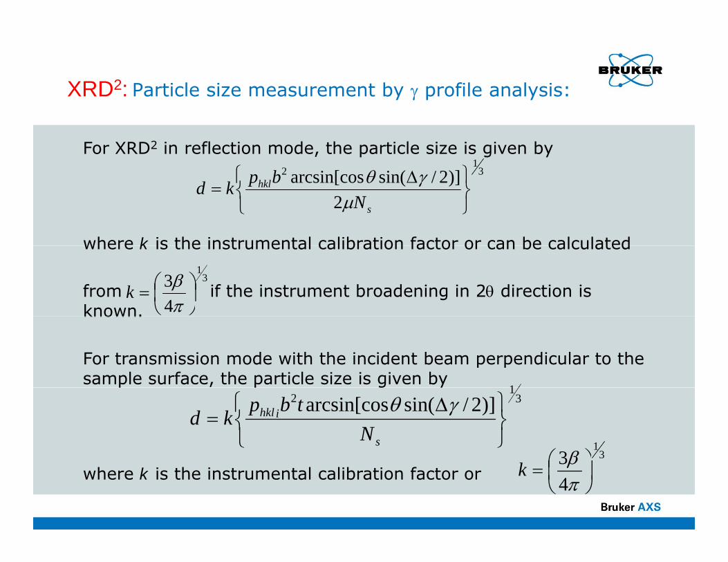
XRD2: Particle size measurement by γ profile analysis:
For XRD2 in reflection mode, the particle size is given by3
12 )]2/sin(arcsin[cos ⎫⎧ Δbp γθ
where k is the instrumental calibration factor or can be calculated
2)]2/sin(arcsin[cos
⎭⎬⎫
⎩⎨⎧ Δ
=s
hkl
Nbpkd
μγθ
where k is the instrumental calibration factor or can be calculated
from if the instrument broadening in 2θ direction is known.
31
43
⎟⎠⎞
⎜⎝⎛=
πβk
known.
For transmission mode with the incident beam perpendicular to the sample surface, the particle size is given by
1p p g y
31
2 )]2/sin(arcsin[cos
⎭⎬⎫
⎩⎨⎧ Δ
=s
ihkl
Ntbp
kdγθ
31
3 ⎞⎛ βwhere k is the instrumental calibration factor or 4
3⎟⎠⎞
⎜⎝⎛=
πβk

XRD2: Particle size measurement by γ profile analysis:
The frame was collected from a SRM660a (LaB6) ( )sample in transmission mode and Cu-Kα x-rays.The 2D detector (Hi-St ) i t t 23 75
(111) (110) (100)Star™) is set at 23.75 cm from the instrument center. The beam (collimator The beam (collimator pinhole) size b is 200 μm.The sample thickness tpis 7.0 μm, based on the calculated μ of 1138 cm-1 and the measured transmission of 0 45transmission of 0.45.

XRD2: Particle size measurement by γ profile analysis:
The 2θ-integrated plots (γ-profiles) of three rings from (100) (110) and (111) planes 120
140
160
(100)
(100), (110) and (111) planes are displayed.The number of crystallites is counted from the number of i i f h fil
0
20
40
60
80
100
intersections of the γ-profile with a threshold line. To cancel out the effects of the overall intensity fluctuation
90
140
190
240
-111 -106 -101 -96 -91 -86 -81 -76 -71γ
(110)
(texture, etc.), a 2nd order polynomial trend line is fitted to each γ-profile as a threshold line. 70
80
-10
40
90
-113 -108 -103 -98 -93 -88 -83 -78 -73 -68γ
Every two intersections of γ-profile with the threshold line represents a crystallite.New analysis strategy?10
20
30
40
50
60 (111)
New analysis strategy?Size distribution?
0-109 -104 -99 -94 -89 -84 -79 -74γ

XRD2: Particle size measurement by γ profile analysis:
Calibration Results:
(hkl) 2θ N k(hkl) hklP 2θ Δω Ns k(100) 6 21.36 38 23 0.1217(110) 12 30.38 46 41 0.1106(111) 8 37 44 42 38 0 1281
The average scaling factor k is 0.12 in this calibration. The system can then be used to measure the crystallite size of unknown materials if the
(111) 8 37.44 42 38 0.1281
then be used to measure the crystallite size of unknown materials if the data can be collected in approximately the same condition. It is always necessary to calibrate the system with a known standard, preferably with a comparable sample geometry and crystallite size. Fo eflection mode it is c itical to ha e a standa d ith a compa able For reflection mode, it is critical to have a standard with a comparable linear absorption coefficient so as to have similar penetration.

XRD2: Particle Size Analysis by X ray Diffraction:XRD2: Particle Size Analysis by X-ray Diffraction:2 profile analysisθ γ profile analysis
1 nm 10 nm 100 nm 1 mμ 10 mμ 100 mμ 1 mm
particle size range in pharmaceutical systems
2θ profile analysis, including measurement from peak FWHM 2θ profile analysis, including measurement from peak FWHM by Scherrer equation, or profile analysis by Stokes and Wilson, is suitable for particle size below 100 nm.γ profile analysis, based on sampling statistics, is suitable γ profile analysis, based on sampling statistics, is suitable for particle size from sub-micrometer to a few millimeters.The particle size range of pharmaceutical substances is from sub-micrometer to a few millimeters.
18.05.2011Bruker Confidential40
from sub micrometer to a few millimeters.

More About XRD2
1. Introduction. 2. Geometry Conventions.2. Geometry Conventions. 3. X-Ray Source and Optics. 4. X-Ray Detectors.
G S S5. Goniometer and Sample Stages. 6. Data Treatment. 7 Phase Identification7. Phase Identification. 8. Texture Analysis. 9. Stress Measurement. 10. Small-Angle X-Ray Scattering. 11. Combinatorial Screening. 12 Quantitative Analysis
41
12. Quantitative Analysis.13. Innovation and Future Development.

Thank You for Your AttentionThank You for Your Attention
18.05.2011Bruker Confidential42