Embed Size (px)
Citation preview

3 V
alve
gat
e sy
s-te
ms
Valve gate systems

2
4
3
1
3 VALVE GATE SYSTEMS
3.0.20 We reserve the right to make technical changes. 01/18
Valve gate technologyHigh visual requirements, a variety of applications, minimal shear stress, variable gate diameters and high process reliability. These are just a few of the requirements for which GÜNTHER valve gate technology has the right answer.

A
B
3.0.2001/18 We reserve the right to make technical changes.
GÜNTHER’s portfolio includes a variety of valve gate nozzles and needle actuation options. This enables perfect application-specific adaptation to the mould concept, both technically and financially. Both the smallest and large shot volumes and gate diameters from 0.8 to 4.0 mm can be implemented with valve gate technology. The innovative design of the needle guide and the optimised shut-off needle enable low-wear operation. During the shut-off movement, the needle is first led over a cone up
to the cylindrical pre-centring device for precise immersion into the cylindrical gate point. The needle guide is supported floating in the melt channel. In case of wear, the needle guide can be changed with minimal effort . Special openings in the mould clamping plate enable individual adjustment of the immersion depth of the shut-off needle from the outside. Depending on the application, highly filled plastics can be processed.
1 ENV single-needle valve
A Adjustment of the needle position
B Installation independent of heat expansion
2 Needle guide and sealing in the manifold
3 Heated connecting nozzle
4 Needle guide in the nozzle
POSSIBLE NEEDLE GUIDE DESIGNS
LA NEEDLE GUIDE
Second mark on the part
KA NEEDLE GUIDE
Application-dependent use
THE ADVANTAGES AT A GLANCE
Unambiguous opening behaviour
Consistent gate point quality
Sequential injection
Long needle guide service life
Time and cost savings
Wear parts are easy to replace

Overview of overall designSingle valve gate nozzles
Clamping plate
Location ring
Frame plate
Cavity plate
Permanent power connection
Permanent thermocouple plug connection
Power connector CMT
Thermocouple connector CMLK
3.1 VALVE GATE SYSTEMS | SINGLE VALVE GATE NOZZLES
3.1.10 We reserve the right to make technical changes. 01/18

3.1.1001/18 We reserve the right to make technical changes.
3.1 Single valve gate nozzles
SINGLE VALVE GATE NOZZLES Page
8NEST 20Single nozzle with conventional heating element and heated nozzle adapter, needle guide versions LA, LA with titanium ring, LAZ and KA
12NEST 30Single nozzle with conventional heating element and heated nozzle adapter, needle guide versions LA, LA with titanium ring and KA
TECHNICAL DATA
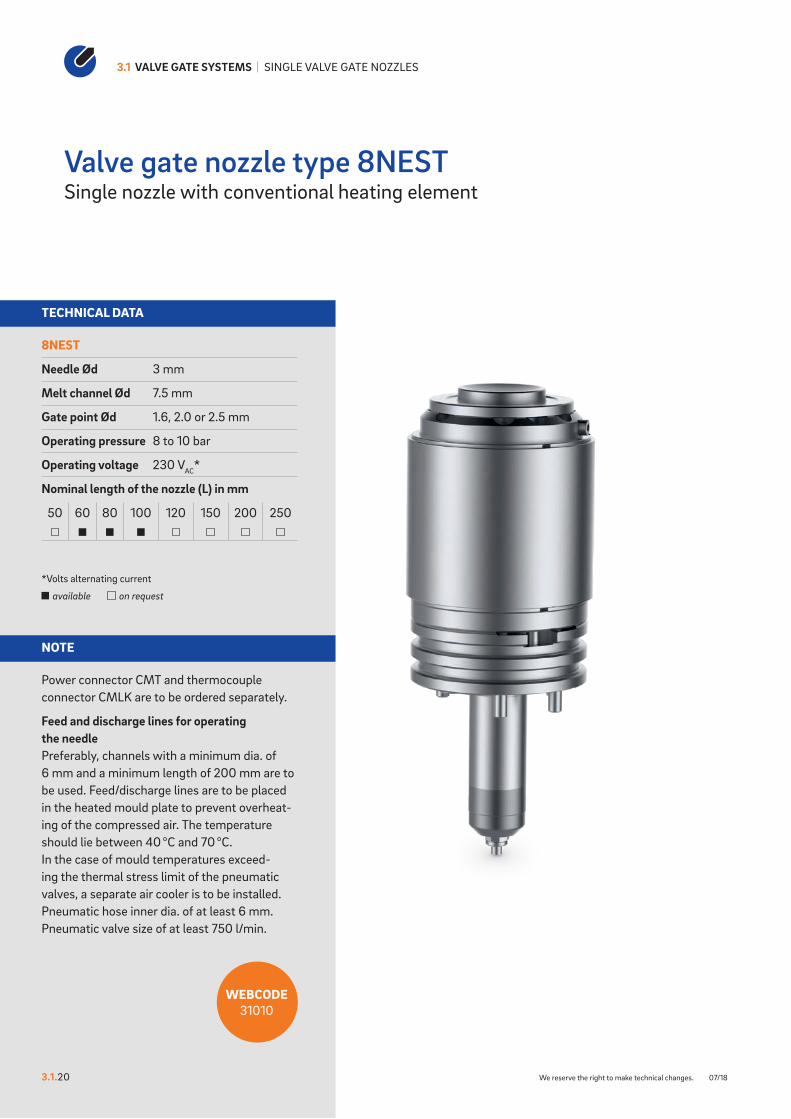
8NEST
Needle Ød 3 mm
Melt channel Ød 7.5 mm
Gate point Ød 1.6, 2.0 or 2.5 mm
Operating pressure 8 to 10 bar
Operating voltage 230 VAC*
Nominal length of the nozzle (L) in mm
50 60 80 100 120 150 200 250
*Volts alternating current
available on request
NOTE
Power connector CMT and thermocouple connector CMLK are to be ordered separately.
Feed and discharge lines for operating the needlePreferably, channels with a minimum dia. of 6 mm and a minimum length of 200 mm are to be used. Feed/discharge lines are to be placed in the heated mould plate to prevent overheat-ing of the compressed air. The temperature should lie between 40 °C and 70 °C. In the case of mould temperatures exceed-ing the thermal stress limit of the pneumatic valves, a separate air cooler is to be installed. Pneumatic hose inner dia. of at least 6 mm. Pneumatic valve size of at least 750 l/min.
3.1 VALVE GATE SYSTEMS | SINGLE VALVE GATE NOZZLES
3.1.20 We reserve the right to make technical changes. 07/18
Valve gate nozzle type 8NESTSingle nozzle with conventional heating element
WEBCODE31010

78
100
126
131,
10 A
ngle
/ Ra
dius
(127
,10
Stra
ight
)
L + 0,
020
50
20
6,1
12
R/W
6,5
4
28 ±0,02
C C
L L
Z
6 x M10 ...12.9
Cavity plate
Fram
e pl
ate
Clamping plate
Location ring
1
5
4
3
2
Strombuchse CMT und Temperaturstecker CMLK sind seperat zu bestellen.
Schnitt C-C: Ausnehmung fürDüsenkopf, Strom-und Temperaturanschluss
10
2
25
4x 6 15M6-6H 12
Ø 6,05x90°, oben
R31 ±0,05
40°
27,50° 27,50°
60
±0,
1
Schnitt L-L: Bohrung für Zu- / Abluft,Befestigungsgewinde, Zentrier- / Positionierstift
Needle closed Ø 6 mm
Needle open Ø 6 mm
Pin position Ø 6,1 mm
("K
")
27 H7
0,5x
45°
50+0
,1
26,5 0+0,4
R2
R2
35
L0+0
,02
26 H7
90°
45°
45°
10,9
-0,2012,6 0
+0,1„X“
Geschlossene Düse mit Nadelführung- Vorkammer - Ausführungen LA
6,3
6,3
1,6
1,6
0,02 A
0,02 A
A
27 H7
0,5x
45°
50+0
,1
26,5 0+0,4
26 H7
R290°
35
L0+0
,02
R8
45°
45°
1,2
-0,10
10,9
-0,20
Geschlossene Düse mit Nadelführung- Vorkammer - Ausführung KA
1,6
1,6
6,3
6,3
0.02 A
0.02 A
A
3.1.2007/18 We reserve the right to make technical changes.
Valve gate nozzle type 8NEST
Detail “Z”
Cross-section C-C: Cutout for nozzle head, power and thermocouple plug connections
For “X” version of the needle guide see following page
Cross-section L-L: Hole for feed/discharge air, fastening thread and centring/positioning pin
INSTALLATION
1 Power and thermocouple plug con-nections in this area can be bent once; minimum radius: R8
2 Thermocouple connector CMLK
3 Power connector CMT4 Permanent thermocouple plug
connection5 Permanent power connection
∆T (°C) 100 150 200 250 300 350
K (mm) 0.09 0.16 0.23 0.29 0.36 0.42
Dimension “K” required for heat expansion is to be ensured by grinding the location ring! Determine the difference between the height of the nozzle (with mount) and the height of the structure when installed! ∆T specifies the temperature differential between the processing temperature and the mould temperature! A pre-tension of 0.03 mm is taken into account for the K dimensions.
Nozzle with needle guide antechamber design KA
Nozzle with needle guide antechamber design LA

Detail X: Ausführung NadelführungVorkammer - Ausführung LA
Ausführung NadelführungVorkammer - Ausführung LA
5 H7
7 -00,1
2,2
0
4,2
0 -0 0,
02
60°
R0,40
7,40 -00,1
90°
R0,40
1,2
±0
,05
scharfkantig,gratfrei
0,4
0,01 A
0.01 A
A
Detail X: Ausführung NadelführungVorkammer - Ausführung LA
Ausführung NadelführungVorkammer - Ausführung LA
5 H7
7 -00,1
2,2
0
4,2
0 -0 0,
02
60°
R0,40
7,40 -00,1
90°
R0,40
1,2
±0
,05
0,4
0,01 A
0.01 A
A
sharp-edged, burr-free
Detail X: Ausführung NadelführungVorkammer - Ausführung LAmit Titanring
Ausführung NadelführungVorkammer - Ausführung LAmit Titanring
5 H7
10 H7
R0,40R0,20R 0,40
60°
60°
2,4
-0,0
20
4,2
10,35
6,39
1,2
±0,0
5
1,5
scharfkantig,gratfrei
1.6
0.4
0.4
0.01 A
0.01 A
0.01 A
A
Detail X: Ausführung NadelführungVorkammer - Ausführung LAmit Titanring
Ausführung NadelführungVorkammer - Ausführung LAmit Titanring
5 H7
10 H7
R0,40R0,20R 0,40
60°
60°
2,4
-0,0
20
4,2
10,35
6,39
1,2
±0,0
5
1,5
1.6
0.4
0.4
0.01 A
0.01 A
0.01 A
A
sharp-edged, burr-free
3.1 VALVE GATE SYSTEMS | SINGLE VALVE GATE NOZZLES
3.1.21 We reserve the right to make technical changes. 01/18
NEEDLE GUIDE VERSIONS
Needle guide version Antechamber version LA
Needle guide version Antechamber version LA
with titanium ring
Valve gate nozzle type 8NESTNeedle guide versions LA, LA with titanium ring, LAZ and KA
Needle guide LAMade of powder-metallurgical steel
If necessary, the needle guide can be changed without great effort. By replacing the needle guide and needle, the gate point diameter can be made larger or smaller without sub-sequent reworking of the mould cavity. Thanks to a precise needle guide, the clean gate point can be closed with nearly no wear or burring.
Advantages:- Long service life and wear-resistance- Wear parts are easy to replace- Outstanding and flash-free gate point quality- Very good visual surface quality- No replacement or subsequent reworking of the
mould inserts required- Minimal shear stress
Needle guide LASpecial version with titanium ring
Thermal insulation of the needle guide using a titanium ring expands the area of use of the valve gate nozzle to include the following plastics:- Polyamides (PA4.6, PA6.6 and HTN)- Thermoplastic polyesters (PBT and PET)- Liquid crystalline polymers (LCP)- Polyether ether ketones (PEEK)

Detail X: Ausführung NadelführungVorkammer - Ausführung LAZ
Ausführung NadelführungVorkammer - Ausführung LAZ
90°
70° R0,40
R0,40
S7 -00,1
3,50 H6
4,2
0 -0 0,
02
7,4 -0,10
t6±0
,05
t50+ 0
,05
0,4
0,4
0,01 A
0.01 A
A
scharfkantig,gratfrei
Detail X: Ausführung NadelführungVorkammer - Ausführung LAZ
Ausführung NadelführungVorkammer - Ausführung LAZ
90°
70° R0,40
R0,40
S7 -00,1
3,50 H6
4,2
0 -0 0,
02
7,4 -0,10
t6±0
,05
t50+ 0
,05
0,4
0,4
0,01 A
0.01 A
A
sharp-edged, burr-free
45°
R0,5
0,5
-0 0,1
D ++
0,0070,003
Detail Y: Ausführung NadelführungVorkammer - Ausführung KA
1,6
geschlien0,2
0,005 A
A
Ausführung NadelführungVorkammer - Ausführung KA
sharp-edged, burr-free
45°
R0,5
0,5
-0 0,1
D ++
0,0070,003
Detail Y: Ausführung NadelführungVorkammer - Ausführung KA
1,6
geschlien0,2
0,005 A
A
Ausführung NadelführungVorkammer - Ausführung KA
sharp-edged, burr-free
3.1.2107/18 We reserve the right to make technical changes.
Needle guide version Antechamber version LAZ
Needle guide version Antechamber version KA
Valve gate nozzle type 8NEST
Needle guide LAZMade of powder-metallurgical steel
If necessary, the needle guide can be changed without great effort. By replacing the needle guide and needle, the gate point diameter can be made larger or smaller without subsequent reworking of the mould cavity. Thanks to a precise needle guide, the clean gate point can be closed with nearly no wear or burring. Needle guide type LAZ has a tapered shape with a smaller contact surface which creates a smaller impression. This version is suitable for items with a minimal wall thickness and part geometries not permitting a larger impression.
Advantages:- Long service life and wear-resistance- Wear parts are easy to replace- Outstanding and flash-free gate point quality- Very good visual surface quality- No replacement or subsequent reworking of the
mould inserts required- Minimal shear stress
Needle guide KAThis is used when a second marking on the part is not permissible.
When selecting the material to be used, the needle hardness of 64 ±2 HRC is to be taken into account!
Installation dimensions of needle guide version LAZ
ØD ØS7 t5 t61.6 3.0 0.63 0.772.0 3.5 0.63 1.072.5 4.0 0.58 1.43

TECHNICAL DATA
12NEST
Needle Ød 5 mm
Melt channel Ød 12 mm
Gate point Ød 3.0, 3.5 or 4.0 mm
Operating pressure 8 to 10 bar
Operating voltage 230 VAC*
Nominal length of the nozzle (L) in mm
60 80 100 120 150 200 250
*Volts alternating current
available on request
NOTE
Power connector CMT and thermocouple connector CMLK are to be ordered separately.
Feed and discharge lines for operating the needlePreferably, channels with a minimum dia. of 6 mm and a minimum length of 200 mm are to be used. Feed/discharge lines are to be placed in the heated mould plate to prevent overheat-ing of the compressed air. The temperature should lie between 40 °C and 70 °C. In the case of mould temperatures exceed-ing the thermal stress limit of the pneumatic valves, a separate air cooler is to be installed. Pneumatic hose inner dia. of at least 6 mm. Pneumatic valve size of at least 750 l/min.
3.1 VALVE GATE SYSTEMS | SINGLE VALVE GATE NOZZLES
3.1.30 We reserve the right to make technical changes. 07/18
Valve gate nozzle type 12NESTSingle nozzle with conventional heating element
WEBCODE31030

Location ring
19
6,1
78
119
145
150,
10 A
ngle
/ Ra
dius
(146
,28
Stra
ight
)
L + 0,
020
50
20
R/W
10
4
28,50 ±0,02
C C
L L
Z
6 x M10 ...12.9
Cavity plate
Fram
e pl
ate
Clamping plate
1
3
2
4
5
25
122
Schnitt C-C: Ausnehmung fürDüsenkopf, Strom-und Thermofühleranschluss
4 x 6,80 22,25M8-6H 16
Ø 8,05x90°, Oben
R40 ±0,05
40°
22,50° 22,50°
72
±0,
05
Needle closed Ø 6 mm
Schnitt L-L: Bohrung für Zu- / Abluft,Befestigungsgewinde, Zentrier- / Positionierstift
Pin position Ø 6,1 mm
Needle open Ø 6 mm
Detail "Z"
("K
")
39 H7
0,5x
45°
100+0
,1
38,5 0+0,4
38 H7
39
L0+0
,02
R2
R12
90°
45°
45°
1,2
-0,10
15,3
-0,20
Geschlossene Düse mit Nadelführung- Vorkammer - Ausführung KA
1,6
1,6
6,3
6,3
0.02 A
0.02 A
A
R2
39 H7
0,5x
45°
100+0
,1
38,5 0+0,4
R2 39
L0+0
,02
38 H7
45°
45°
90°
15,3
-0,20
„X“
Geschlossene Düse mit Nadelführung- Vorkammer - Ausführungen LA
6,3
6,3
1,6
1,6
0,02 A
0,02 A
A
3.1.3007/18 We reserve the right to make technical changes.
Valve gate nozzle type 12NEST
View C-C: Cutout for nozzle head, power and thermocouple plug connections
Cross-section L-L: Hole for feed/discharge air, fastening thread and centring/positioning pin
INSTALLATION
1 Power and thermocouple plug connections in this area can be bent once; minimum radius: R8
2 Thermocouple connector CMLK
3 Power connector CMT4 Permanent thermocouple plug
connection5 Permanent power connection
∆T (°C) 100 150 200 250 300 350
K (mm) 0.11 0.19 0.26 0.33 0.41 0.48
Dimension “K” required for heat expansion is to be ensured by grinding the location ring! Determine the difference between the height of the nozzle (with mount) and the height of the structure when installed! ∆T specifies the temperature differential between the processing temperature and the mould temperature! A pretension of 0.03 mm is taken into account for the K dimensions.
Nozzle with needle guide antechamber design KA
Nozzle with needle guide antechamber design LA
Detail “Z”
For “X” version of the needle guide see following page

10,4 -00,1
6,5 H7 4,8
-0 0,02
2,6
60°
90°
R0,8
R1,2
1,32
±0,0
5
10,8 -00,1
0.4
0.4
0.01 A
0.01 A
A
Detail X: Ausführung NadelführungVorkammer - Ausführung LA
Ausführung NadelführungVorkammer - Ausführung LA
sharp-edged, burr-free
10,4 -00,1
6,5 H7 4,8
-0 0,02
2,6
60°
90°
R0,8
R1,2
1,32
±0,0
5
10,8 -00,1
0.4
0.4
0.01 A
0.01 A
A
Detail X: Ausführung NadelführungVorkammer - Ausführung LA
Ausführung NadelführungVorkammer - Ausführung LA
sharp-edged, burr-free
6,5 H714,5 H7
R1,20R0,20
R0,40
60°
2,2
-0,0
20
4,8
14,85
7,52
60°
1,32
±0,0
5
2,3
0.4
0.4
1.6
0.01 A
0.01 A
0.01 A
A
Detail X: Ausführung NadelführungVorkammer - Ausführung LAmit Titanring
Ausführung NadelführungVorkammer - Ausführung LAmit Titanring
sharp-edged, burr-free
6,5 H714,5 H7
R1,20R0,20
R0,40
60°
2,2
-0,0
20
4,8
14,85
7,52
60°
1,32
±0,0
5
2,3
0.4
0.4
1.6
0.01 A
0.01 A
0.01 A
A
Detail X: Ausführung NadelführungVorkammer - Ausführung LAmit Titanring
Ausführung NadelführungVorkammer - Ausführung LAmit Titanring
sharp-edged, burr-free
3.1 VALVE GATE SYSTEMS | SINGLE VALVE GATE NOZZLES
3.1.31 We reserve the right to make technical changes. 01/18
NEEDLE GUIDE VERSIONS
Needle guide version Antechamber version LA
Needle guide version Antechamber version LA
with titanium ring
Valve gate nozzle type 12NESTNeedle guide versions LA, LA with titanium ring and KA
Needle guide LAMade of powder-metallurgical steel
If necessary, the needle guide can be changed without great effort. By replacing the needle guide and needle, the gate point diameter can be made larger or smaller without sub-sequent reworking of the mould cavity. Thanks to a precise needle guide, the clean gate point can be closed with nearly no wear or burring.
Advantages:- Long service life and wear-resistance- Wear parts are easy to replace- Outstanding and flash-free gate point quality- Very good visual surface quality- No replacement or subsequent reworking of the
mould inserts required- Minimal shear stress
Needle guide LASpecial version with titanium ring
Thermal insulation of the needle guide using a titanium ring expands the area of use of the valve gate nozzle to include the following plastics:- Polyamides (PA4.6, PA6.6 and HTN)- Thermoplastic polyesters (PBT and PET)- Liquid crystalline polymers (LCP)- Polyether ether ketones (PEEK)

D ++
0,0070,003
R0,5
0,5
-0 0,1
45°
Detail Y: Ausführung NadelführungVorkammer - Ausführung KA
1,6
ground0,2
0,005 A
A
Ausführung NadelführungVorkammer - Ausführung KA
sharp-edged, burr-free
D ++
0,0070,003
R0,5
0,5
-0 0,1
45°
Detail Y: Ausführung NadelführungVorkammer - Ausführung KA
1,6
ground0,2
0,005 A
A
Ausführung NadelführungVorkammer - Ausführung KA
sharp-edged, burr-free
3.1.3101/18 We reserve the right to make technical changes.
Valve gate nozzle type 12NEST
Needle guide version Antechamber version KA
Needle guide KAThis is used when a second marking on the part is not permissible.
When selecting the material to be used, the needle hardness of 64 ±2 HRC is to be taken into account!


3.2.1001/18 We reserve the right to make technical changes.
3.2 VALVE GATE SYSTEMS | SYSTEM VALVE GATE NOZZLES
3.2 System valve gate nozzles
SINGLE VALVE GATE NOZZLES Page
4NHF, 5NHF and 6NHF 30, 40, 50System nozzle with thick-film heating element (BlueFlow®), screwed to the manifold, needle guide versions LA, LA with titanium ring, LAZ and KA
5NHT and 6NHT 60, 70System nozzle with conventional heating element screwed to the manifold, needle guide versions LA, LA with titanium ring, LAZ and KA
8NHT, 10NHT and 12NHT 80, 90, 100System nozzle with conventional heating element screwed to the manifold, needle guide versions LA, LA with titanium ring, LAZ and KA
5NMT and 6NMT 110, 120System nozzle with conventional heating element, for minimal spacing not screwed to the manifold, needle guide versions LA, LA with titanium ring, LAZ and KA
4NTT, 5NTT and 6NTT 130, 140, 150System nozzle with conventional heating element screwed from the parting line, needle guide versions LA, LA with titanium ring, LAZ and KA

3.2 VALVE GATE SYSTEMS | SYSTEM VALVE GATE NOZZLES
3.2.20 We reserve the right to make technical changes. 01/18
Overview of overall designSystem valve gate nozzles
AValve gate nozzle type NTT - With shaft - Screwed from the parting line
BValve gate nozzle type NHT - With shaft - Screwed to the manifold
Clamping plate
Nozzle holding plate
Plug-in type power and thermocouple plug connections
Cavity plate
A B

3.2.2001/18 We reserve the right to make technical changes.
CValve gate nozzle type NMT - With shaft - For minimal spacing - Not screwed to the manifold
DBlueFlow® valve gate nozzle type NHF - With shaft - Thick-film heating element (BlueFlow®) - Screwed to the manifold
Clamping plate
Nozzle holding plate
Plug-in type thermocouple and power plug connections
Cavity plate
C D

TECHNICAL DATA
4NHF
Needle Ød 2 mm
Melt channel Ød 3.8 mm
Gate point Ød 0.8, 1.0, 1.2 or 1.4 mm
Operating voltage 230 VAC*
Nominal length of the nozzle (L) in mm
50 60 80 100 120 150 180
Contact us for other nozzle lengths!
*Volts alternating current
available on request
NOTE
Power connector CHF and thermocouple connector CMLK are to be ordered separately.
BlueFlow® hot runner nozzle type NHF is not intended for sale or use in the USA or Canada!
3.2 VALVE GATE SYSTEMS | SYSTEM VALVE GATE NOZZLES
3.2.30 We reserve the right to make technical changes. 01/18
Valve gate nozzle type 4NHFSystem nozzle with thick-film heating element (BlueFlow®), screwed to the manifold
WEBCODE32010
38
L
+ 0,02
0
min
. 29
3,8
min
. 30
("K
")
1Shut-o� needle
VH
Clamping plate
Nozzle holding plate
Manifold
Cavity plate
60
130
20
SW
28
45° 45°
Thermocouple connectorCMLK
PowerconnectorCHF
0,5x
45°
50+0
,1
16 H7
R2 90°
15 H7
15,5 +
0,40
L + 0,
020
29
R8
45°
45°
6,7
-0 0,2
1,2
-0 0,
1
Geschlossene Düse mit Nadelführung- Vorkammer - Ausführungen KA
1,6
1,6
6,3
6,3
0,02 A
0,02 A
A
90°
29
L0+0
,02
0,5x
45
50+0
,10
16 H7
15,5 0+0,4
15 H7
„X“
R2
R2
45°
45°
8 0+0,1
6,7
-0,20
Geschlossene Düse mit Nadelführung- Vorkammer - Ausführungen LA
1,6
1,6
6,3
6,3
0,02 A
0,02 A
A
3.2.3001/18 We reserve the right to make technical changes.
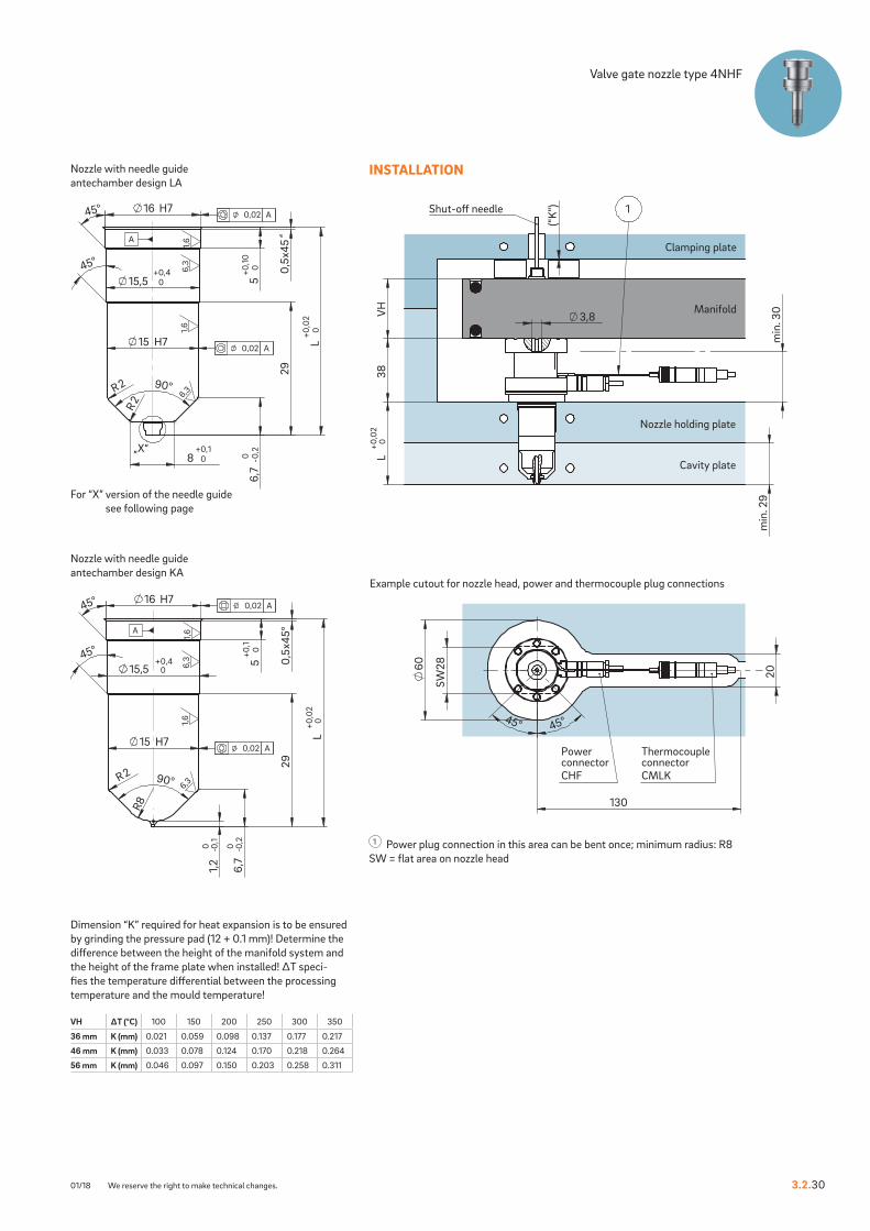
Valve gate nozzle type 4NHF
Example cutout for nozzle head, power and thermocouple plug connections
INSTALLATION
1 Power plug connection in this area can be bent once; minimum radius: R8SW = flat area on nozzle head
Nozzle with needle guide antechamber design KA
Nozzle with needle guide antechamber design LA
VH ∆T (°C) 100 150 200 250 300 350
36 mm K (mm) 0.021 0.059 0.098 0.137 0.177 0.217
46 mm K (mm) 0.033 0.078 0.124 0.170 0.218 0.264
56 mm K (mm) 0.046 0.097 0.150 0.203 0.258 0.311
Dimension “K” required for heat expansion is to be ensured by grinding the pressure pad (12 + 0.1 mm)! Determine the difference between the height of the manifold system and the height of the frame plate when installed! ∆T speci-fies the temperature differential between the processing temperature and the mould temperature!
For “X” version of the needle guide see following page

10+0
,1
3,20
-0,0
20
3,50 H7
-0,10
-0,100
60°
90°
R0,4
Detail X: Ausführung NadelführungVorkammer - Ausführung LA
0,4
0,4
0,01 A
0,01 A
Ausführung NadelführungVorkammer - Ausführung LA
sharp-edged, burr-free
3,9
4,1
1,85
10+0
,1
3,20
-0,0
20
3,50 H7
-0,10
-0,100
60°
90°
R0,4
Detail X: Ausführung NadelführungVorkammer - Ausführung LA
0,4
0,4
0,01 A
0,01 A
Ausführung NadelführungVorkammer - Ausführung LA
sharp-edged, burr-free
3,9
4,1
1,85
R0,4
R0,2
R0,4
60°
60°
1,4
0 -0 0,
02
3,2
0
3,50 H7
1 + 0,
10
Detail X: Ausführung NadelführungVorkammer - Ausführung LAmit Titanring
1.6
0,4
0,4
0,01 A
0,01 A
0,01 A
A
Ausführung NadelführungVorkammer - Ausführung LAmit Titanring
sharp-edged, burr-free
6,5 H7
1,4
R0,4
R0,2
R0,4
60°
60°
1,4
0 -0 0,
02
3,2
0
3,50 H7
1 + 0,
10
Detail X: Ausführung NadelführungVorkammer - Ausführung LAmit Titanring
1.6
0,4
0,4
0,01 A
0,01 A
0,01 A
A
Ausführung NadelführungVorkammer - Ausführung LAmit Titanring
sharp-edged, burr-free
6,5 H7
1,4
3.2 VALVE GATE SYSTEMS | SYSTEM VALVE GATE NOZZLES
3.2.31 We reserve the right to make technical changes. 07/18
NEEDLE GUIDE VERSIONS
Needle guide version Antechamber version LA
Needle guide version Antechamber version LA
with titanium ring
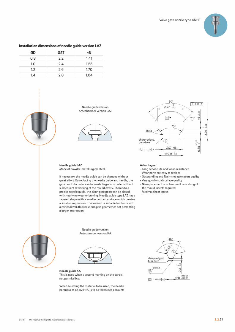
Valve gate nozzle type 4NHFNeedle guide versions LA, LA with titanium ring, LAZ and KA
Needle guide LAMade of powder-metallurgical steel
If necessary, the needle guide can be changed without great effort. By replacing the needle guide and needle, the gate point diameter can be made larger or smaller without sub-sequent reworking of the mould cavity. Thanks to a precise needle guide, the clean gate point can be closed with nearly no wear or burring.
Advantages:- Long service life and wear-resistance- Wear parts are easy to replace- Outstanding and flash-free gate point quality- Very good visual surface quality- No replacement or subsequent reworking of
the mould inserts required- Minimal shear stress
Needle guide LASpecial version with titanium ring
Thermal insulation of the needle guide using a titanium ring expands the area of use of the valve gate nozzle to include the following plastics:- Polyamides (PA4.6, PA6.6 and HTN)- Thermoplastic polyesters (PBT and PET)- Liquid crystalline polymers (LCP)- Polyether ether ketones (PEEK)
-0,10
90°
S7 H6
70°
-0,10
3,20
-0,0
20
t6±0
,05
0,58
0+ 0,0
5
R0,4
Detail X: Ausführung NadelführungVorkammer - Ausführung LAZ
0,4
0,4
0.01 A
0,01 A
A
Ausführung NadelführungVorkammer - Ausführung LAZ
sharp-edged, burr-free
4,1
3,9
-0,10
90°
S7 H6
70°
-0,10
3,20
-0,0
20
t6±0
,05
0,58
0+ 0,0
5
R0,4
Detail X: Ausführung NadelführungVorkammer - Ausführung LAZ
0,4
0,4
0.01 A
0,01 A
A
Ausführung NadelführungVorkammer - Ausführung LAZ
sharp-edged, burr-free
4,1
3,9
R0,
5
45°
0,3
-0 0,1
D ++
0,0070,003
Detail Y: Ausführung NadelführungVorkammer - Ausführung KA
1,6
ground0,2
0,005 A
Ausführung NadelführungVorkammer - Ausführung KA
sharp-edged, burr-free
R0,
5
45°
0,3
-0 0,1
D ++
0,0070,003
Detail Y: Ausführung NadelführungVorkammer - Ausführung KA
1,6
ground0,2
0,005 A
Ausführung NadelführungVorkammer - Ausführung KA
sharp-edged, burr-free
3.2.3107/18 We reserve the right to make technical changes.
Valve gate nozzle type 4NHF
Needle guide version Antechamber version LAZ
Needle guide version Antechamber version KA
Installation dimensions of needle guide version LAZ
ØD ØS7 t60.8 2.2 1.411.0 2.4 1.551.2 2.6 1.701.4 2.8 1.84
Needle guide LAZMade of powder-metallurgical steel
If necessary, the needle guide can be changed without great effort. By replacing the needle guide and needle, the gate point diameter can be made larger or smaller without subsequent reworking of the mould cavity. Thanks to a precise needle guide, the clean gate point can be closed with nearly no wear or burring. Needle guide type LAZ has a tapered shape with a smaller contact surface which creates a smaller impression. This version is suitable for items with a minimal wall thickness and part geometries not permitting a larger impression.
Advantages:- Long service life and wear-resistance- Wear parts are easy to replace- Outstanding and flash-free gate point quality- Very good visual surface quality- No replacement or subsequent reworking of
the mould inserts required- Minimal shear stress
Needle guide KAThis is used when a second marking on the part is not permissible.
When selecting the material to be used, the needle hardness of 64 ±2 HRC is to be taken into account!

TECHNICAL DATA
5NHF
Needle Ød 3 mm
Melt channel Ød 4.8 mm
Gate point Ød 0.8, 1.0, 1.2 or 1.4 mm
Operating voltage 230 VAC*
Nominal length of the nozzle (L) in mm
50 60 80 100 120 150 180
Contact us for other nozzle lengths!
*Volts alternating current
available on request
NOTE
Power connector CHF and thermocouple connector CMLK are to be ordered separately.
BlueFlow® hot runner nozzle type NHF is not intended for sale or use in the USA or Canada!
3.2 VALVE GATE SYSTEMS | SYSTEM VALVE GATE NOZZLES
3.2.40 We reserve the right to make technical changes. 01/18
Valve gate nozzle type 5NHFSystem nozzle with thick-film heating element (BlueFlow®), screwed to the manifold
WEBCODE32020

38
L
+ 0,02
0
min
. 28
4,8
min
. 30
("K
")
1Shut-o� needle
VH
Clamping plate
Nozzle holding plate
Manifold
Cavity plate
60
130
20
SW
28
45° 45°
Thermocouple connectorCMLK
PowerconnectorCHF
0,5x
45°
50+0
,1
19 H7
R2 90°
18 H7
18,5 +
0,40
L + 0,
020
28
R8
45°
45°
6,9
-0 0,2
1,2
-0 0,
1
Geschlossene Düse mit Nadelführung- Vorkammer - Ausführungen KA
1,6
1,6
6,3
6,3
0,02 A
0,02 A
A
90°
28
L0+0
,02
0,5x
45
50+0
,10
19 H7
18,5 0+0,4
18 H7
R2
R2
45°
45°
10,6 0+0,1
6,9
-0,20
Geschlossene Düse mit Nadelführung- Vorkammer - Ausführungen LA
1,6
1,6
6,3
6,3
0,02 A
0,02 A
A
„X“
3.2.4001/18 We reserve the right to make technical changes.
Valve gate nozzle type 5NHF
Example cutout for nozzle head, power and thermocouple plug connections
INSTALLATION
1 Thermocouple plug connection in this area can be bent once; minimum radius: R8SW = flat area on nozzle head
Nozzle with needle guide antechamber design KA
Nozzle with needle guide antechamber design LA
VH ∆T (°C) 100 150 200 250 300 350
36 mm K (mm) 0.021 0.059 0.098 0.137 0.177 0.217
46 mm K (mm) 0.033 0.078 0.124 0.170 0.218 0.264
56 mm K (mm) 0.046 0.097 0.150 0.203 0.258 0.311
Dimension “K” required for heat expansion is to be ensured by grinding the pressure pad (12 + 0.1 mm)! Determine the difference between the height of the manifold system and the height of the frame plate when installed! ∆T speci-fies the temperature differential between the processing temperature and the mould temperature!
For “X” version of the needle guide see following page

10+0
,1
3,20
-0,0
20
3,50 H7
4,6 -0,10
5 -0,100
60°
90°
1,25
R0,4
Detail X: Ausführung NadelführungVorkammer - Ausführung LA
0,4
0,4
0,01 A
0,01 A
Ausführung NadelführungVorkammer - Ausführung LA
sharp-edged, burr-free
10+0
,1
3,20
-0,0
20
3,50 H7
4,6 -0,10
5 -0,100
60°
90°
1,25
R0,4
Detail X: Ausführung NadelführungVorkammer - Ausführung LA
0,4
0,4
0,01 A
0,01 A
Ausführung NadelführungVorkammer - Ausführung LA
sharp-edged, burr-free
R0,4
R0,2
R0,4
60°
60°
1,4
0 -0 0,
02
3,2
0
3,50 H7
7 H7
1,5
1 + 0,
10
Detail X: Ausführung NadelführungVorkammer - Ausführung LAmit Titanring
1.6
0,4
0,4
0,01 A
0,01 A
0,01 A
A
Ausführung NadelführungVorkammer - Ausführung LAmit Titanring
sharp-edged, burr-free
R0,4
R0,2
R0,4
60°
60°
1,4
0 -0 0,
02
3,2
0
3,50 H7
7 H7
1,5
1 + 0,
10
Detail X: Ausführung NadelführungVorkammer - Ausführung LAmit Titanring
1.6
0,4
0,4
0,01 A
0,01 A
0,01 A
A
Ausführung NadelführungVorkammer - Ausführung LAmit Titanring
sharp-edged, burr-free
3.2 VALVE GATE SYSTEMS | SYSTEM VALVE GATE NOZZLES
3.2.41 We reserve the right to make technical changes. 07/18
NEEDLE GUIDE VERSIONS
Needle guide version Antechamber version LA
Needle guide version Antechamber version LA
with titanium ring
Valve gate nozzle type 5NHFNeedle guide versions LA, LA with titanium ring, LAZ and KA
Needle guide LAMade of powder-metallurgical steel
If necessary, the needle guide can be changed without great effort. By replacing the needle guide and needle, the gate point diameter can be made larger or smaller without sub-sequent reworking of the mould cavity. Thanks to a precise needle guide, the clean gate point can be closed with nearly no wear or burring.
Advantages:- Long service life and wear-resistance- Wear parts are easy to replace- Outstanding and flash-free gate point quality- Very good visual surface quality- No replacement or subsequent reworking of
the mould inserts required- Minimal shear stress
Needle guide LASpecial version with titanium ring
Thermal insulation of the needle guide using a titanium ring expands the area of use of the valve gate nozzle to include the following plastics:- Polyamides (PA4.6, PA6.6 and HTN)- Thermoplastic polyesters (PBT and PET)- Liquid crystalline polymers (LCP)- Polyether ether ketones (PEEK)

5 -0,10
90°
S7 H6
70°
4,6 -0,10
3,20
-0,0
20
t6±0
,05
0,58
0+ 0,0
5
R0,4
Detail X: Ausführung NadelführungVorkammer - Ausführung LAZ
0,4
0,4
0.01 A
0,01 A
A
Ausführung NadelführungVorkammer - Ausführung LAZ
sharp-edged, burr-free
Detail Y: Ausführung NadelführungVorkammer - Ausführung KA
Ausführung NadelführungVorkammer - Ausführung KA
R0,
5
45°
0,3
-0 0,1
D ++
0,0070,003
1,6
ground0,2
0,005 A
sharp-edged, burr-free
Detail Y: Ausführung NadelführungVorkammer - Ausführung KA
Ausführung NadelführungVorkammer - Ausführung KA
R0,
5
45°
0,3
-0 0,1
D ++
0,0070,003
1,6
ground0,2
0,005 A
sharp-edged, burr-free
5 -0,10
90°
S7 H6
70°
4,6 -0,10
3,20
-0,0
20
t6±0
,05
0,58
0+ 0,0
5
R0,4
Detail X: Ausführung NadelführungVorkammer - Ausführung LAZ
0,4
0,4
0.01 A
0,01 A
A
Ausführung NadelführungVorkammer - Ausführung LAZ
sharp-edged, burr-free
3.2.4101/18 We reserve the right to make technical changes.
Valve gate nozzle type 5NHF
Needle guide version Antechamber version LAZ
Needle guide version Antechamber version KA
Installation dimensions of needle guide version LAZ
ØD ØS7 t60.8 2.2 0.911.0 2.4 1.051.2 2.6 1.201.4 2.8 1.34
Needle guide LAZMade of powder-metallurgical steel
If necessary, the needle guide can be changed without great effort. By replacing the needle guide and needle, the gate point diameter can be made larger or smaller without subsequent reworking of the mould cavity. Thanks to a precise needle guide, the clean gate point can be closed with nearly no wear or burring. Needle guide type LAZ has a tapered shape with a smaller contact surface which creates a smaller impression. This version is suitable for items with a minimal wall thickness and part geometries not permitting a larger impression.
Advantages:- Long service life and wear-resistance- Wear parts are easy to replace- Outstanding and flash-free gate point quality- Very good visual surface quality- No replacement or subsequent reworking of
the mould inserts required- Minimal shear stress
Needle guide KAThis is used when a second marking on the part is not permissible.
When selecting the material to be used, the needle hardness of 64 ±2 HRC is to be taken into account!
TECHNICAL DATA
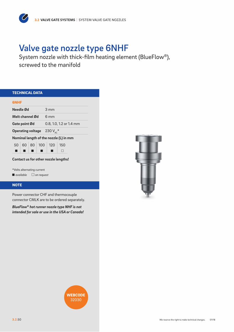
6NHF
Needle Ød 3 mm
Melt channel Ød 6 mm
Gate point Ød 0.8, 1.0, 1.2 or 1.4 mm
Operating voltage 230 VAC*
Nominal length of the nozzle (L) in mm
50 60 80 100 120 150
Contact us for other nozzle lengths!
*Volts alternating current
available on request
NOTE
Power connector CHF and thermocouple connector CMLK are to be ordered separately.
BlueFlow® hot runner nozzle type NHF is not intended for sale or use in the USA or Canada!
3.2 VALVE GATE SYSTEMS | SYSTEM VALVE GATE NOZZLES
3.2.50 We reserve the right to make technical changes. 01/18
Valve gate nozzle type 6NHFSystem nozzle with thick-film heating element (BlueFlow®), screwed to the manifold
WEBCODE32030

38
L
+ 0,02
0
min
. 32
6
min
. 30
("K
")
1Shut-o� needle
VH
Clamping plate
Nozzle holding plate
Manifold
Cavity plate
60
130
20
SW
28
45° 45°
Thermocouple connectorCMLK
PowerconnectorCHF
0,5x
45°
50+0
,1
23 H7
R2 90°
22 H7
22,5 +
0,40
L + 0,
020
32
R8
45°
45°
8,9
-0 0,2
1,2
-0 0,
1
Geschlossene Düse mit Nadelführung- Vorkammer - Ausführungen KA
1,6
1,6
6,3
6,3
0,02 A
0,02 A
A
90°
32
L0+0
,02
0,5x
45
50+0
,10
23 H7
22,5 0+0,4
22 H7
R2
R2
45°
45°
10,6 0+0,1
8,9
-0,20
Geschlossene Düse mit Nadelführung- Vorkammer - Ausführungen LA
1,6
1,6
6,3
6,3
0,02 A
0,02 A
A
„X“
3.2.5001/18 We reserve the right to make technical changes.
Valve gate nozzle type 6NHF
Example cutout for nozzle head, power and thermocouple plug connections
INSTALLATION
1 Thermocouple plug connection in this area can be bent once; minimum radius: R8SW = flat area on nozzle head
Nozzle with needle guide antechamber design KA
Nozzle with needle guide antechamber design LA
VH ∆T (°C) 100 150 200 250 300 350
36 mm K (mm) 0.021 0.059 0.098 0.137 0.177 0.217
46 mm K (mm) 0.033 0.078 0.124 0.170 0.218 0.264
56 mm K (mm) 0.046 0.097 0.150 0.203 0.258 0.311
Dimension “K” required for heat expansion is to be ensured by grinding the pressure pad (12 + 0.1 mm)! Determine the difference between the height of the manifold system and the height of the frame plate when installed! ∆T speci-fies the temperature differential between the processing temperature and the mould temperature!
For “X” version of the needle guide see following page

10+0
,1
3,20
-0,0
20
3,50 H7
4,6 -0,10
5 -0,100
60°
90°
1,25
R0,4
Detail X: Ausführung NadelführungVorkammer - Ausführung LA
0,4
0,4
0,01 A
0,01 A
Ausführung NadelführungVorkammer - Ausführung LA
sharp-edged, burr-free
10+0
,1
3,20
-0,0
20
3,50 H7
4,6 -0,10
5 -0,100
60°
90°
1,25
R0,4
Detail X: Ausführung NadelführungVorkammer - Ausführung LA
0,4
0,4
0,01 A
0,01 A
Ausführung NadelführungVorkammer - Ausführung LA
sharp-edged, burr-free
R0,4
R0,2
R0,4
60°
60°
1,4
0 -0 0,
02
3,2
0
3,50 H7
7 H7
1,5
1 + 0,
10
Detail X: Ausführung NadelführungVorkammer - Ausführung LAmit Titanring
1.6
0,4
0,4
0,01 A
0,01 A
0,01 A
A
Ausführung NadelführungVorkammer - Ausführung LAmit Titanring
sharp-edged, burr-free
R0,4
R0,2
R0,4
60°
60°
1,4
0 -0 0,
02
3,2
0
3,50 H7
7 H7
1,5
1 + 0,
10
Detail X: Ausführung NadelführungVorkammer - Ausführung LAmit Titanring
1.6
0,4
0,4
0,01 A
0,01 A
0,01 A
A
Ausführung NadelführungVorkammer - Ausführung LAmit Titanring
sharp-edged, burr-free
3.2 VALVE GATE SYSTEMS | SYSTEM VALVE GATE NOZZLES
3.2.51 We reserve the right to make technical changes. 07/18
NEEDLE GUIDE VERSIONS
Needle guide version Antechamber version LA
Needle guide version Antechamber version LA
with titanium ring
Valve gate nozzle type 6NHFNeedle guide versions LA, LA with titanium ring, LAZ and KA
Needle guide LAMade of powder-metallurgical steel
If necessary, the needle guide can be changed without great effort. By replacing the needle guide and needle, the gate point diameter can be made larger or smaller without sub-sequent reworking of the mould cavity. Thanks to a precise needle guide, the clean gate point can be closed with nearly no wear or burring.
Advantages:- Long service life and wear-resistance- Wear parts are easy to replace- Outstanding and flash-free gate point quality- Very good visual surface quality- No replacement or subsequent reworking of
the mould inserts required- Minimal shear stress
Needle guide LASpecial version with titanium ring
Thermal insulation of the needle guide using a titanium ring expands the area of use of the valve gate nozzle to include the following plastics:- Polyamides (PA4.6, PA6.6 and HTN)- Thermoplastic polyesters (PBT and PET)- Liquid crystalline polymers (LCP)- Polyether ether ketones (PEEK)

5 -0,10
90°
S7 H6
70°
4,6 -0,10
3,20
-0,0
20
t6±0
,05
0,58
0+ 0,0
5
R0,4
Detail X: Ausführung NadelführungVorkammer - Ausführung LAZ
0,4
0,4
0.01 A
0,01 A
A
Ausführung NadelführungVorkammer - Ausführung LAZ
sharp-edged, burr-free
R0,
5
45°
0,3
-0 0,1
D ++
0,0070,003
Detail Y: Ausführung NadelführungVorkammer - Ausführung KA
1,6
ground0,2
0,005 A
Ausführung NadelführungVorkammer - Ausführung KA
sharp-edged, burr-free
R0,
5
45°
0,3
-0 0,1
D ++
0,0070,003
Detail Y: Ausführung NadelführungVorkammer - Ausführung KA
1,6
ground0,2
0,005 A
Ausführung NadelführungVorkammer - Ausführung KA
sharp-edged, burr-free
5 -0,10
90°
S7 H6
70°
4,6 -0,10
3,20
-0,0
20
t6±0
,05
0,58
0+ 0,0
5
R0,4
Detail X: Ausführung NadelführungVorkammer - Ausführung LAZ
0,4
0,4
0.01 A
0,01 A
A
Ausführung NadelführungVorkammer - Ausführung LAZ
sharp-edged, burr-free
3.2.5101/18 We reserve the right to make technical changes.
Valve gate nozzle type 6NHF
Needle guide version Antechamber version LAZ
Needle guide version Antechamber version KA
Installation dimensions of needle guide version LAZ
ØD ØS7 t60.8 2.2 0.911.0 2.4 1.051.2 2.6 1.201.4 2.8 1.34
Needle guide LAZMade of powder-metallurgical steel
If necessary, the needle guide can be changed without great effort. By replacing the needle guide and needle, the gate point diameter can be made larger or smaller without subsequent reworking of the mould cavity. Thanks to a precise needle guide, the clean gate point can be closed with nearly no wear or burring. Needle guide type LAZ has a tapered shape with a smaller contact surface which creates a smaller impression. This version is suitable for items with a minimal wall thickness and part geometries not permitting a larger impression.
Advantages:- Long service life and wear-resistance- Wear parts are easy to replace- Outstanding and flash-free gate point quality- Very good visual surface quality- No replacement or subsequent reworking of
the mould inserts required- Minimal shear stress
Needle guide KAThis is used when a second marking on the part is not permissible.
When selecting the material to be used, the needle hardness of 64 ±2 HRC is to be taken into account!
TECHNICAL DATA
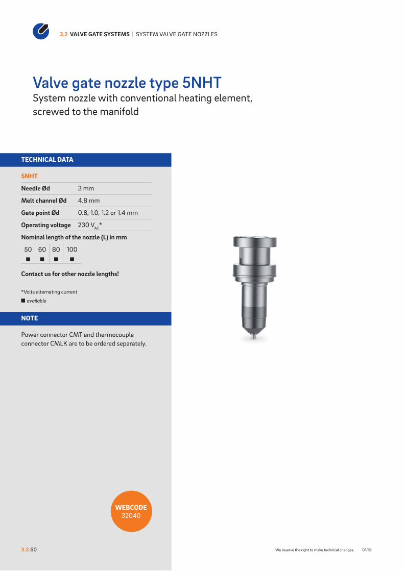
5NHT
Needle Ød 3 mm
Melt channel Ød 4.8 mm
Gate point Ød 0.8, 1.0, 1.2 or 1.4 mm
Operating voltage 230 VAC*
Nominal length of the nozzle (L) in mm
50 60 80 100
Contact us for other nozzle lengths!
*Volts alternating current
available
NOTE
Power connector CMT and thermocouple connector CMLK are to be ordered separately.
3.2 VALVE GATE SYSTEMS | SYSTEM VALVE GATE NOZZLES
3.2.60 We reserve the right to make technical changes. 01/18
Valve gate nozzle type 5NHTSystem nozzle with conventional heating element, screwed to the manifold
WEBCODE32040

38
L
+ 0,02
0
min
. 32
min
. 30
4,8
("K
")
1Shut-o� needle
VH
Clamping plate
Nozzle holding plate
Manifold
Cavity plate
38
L
+ 0,02
0
min
. 32
min
. 30
4,8
("K
")
1Shut-o� needle
VH
Clamping plate
Nozzle holding plate
Manifold
Cavity plate
38
L
+ 0,02
0
min
. 32
min
. 30
4,8
("K
")
1Shut-o� needle
VH
Clamping plate
Nozzle holding plate
Manifold
Cavity plate
38
L
+ 0,02
0
min
. 32
min
. 30
4,8
("K
")
1Shut-o� needle
VH
Clamping plate
Nozzle holding plate
Manifold
Cavity plate
38
L
+ 0,02
0
min
. 32
min
. 30
4,8
("K
")
1Shut-o� needle
VH
Clamping plate
Nozzle holding plate
Manifold
Cavity plate
38
L
+ 0,02
0
min
. 32
min
. 30
4,8
("K
")
1Shut-o� needle
VH
Clamping plate
Nozzle holding plate
Manifold
Cavity plate
38
L
+ 0,02
0
min
. 32
min
. 30
4,8
("K
")
1Shut-o� needle
VH
Clamping plate
Nozzle holding plate
Manifold
Cavity plate
120
20
60
45° 45°
SW
28
Thermocouple connectorCMLK
PowerconnectorCMT
23 H7
22 H7
90°
32
0
,5 x
45
5 + 0,
10
L + 0,
020
22,5 +
0,40
R8
45°
45°
R2
8,9
-0 0,2
1,2
-0 0,
1
Geschlossene Düse mit Nadelführung- Vorkammer Ausführung KA
1,6
1,6
6,3
6,3
0,02 A
0,02 A
A
22 H7
90°R2
R2
22,5 0+0,4
23 H7
50+0
,1
0,5x
45°
45°
32
L0+0
,02
45°
10,6 0+0,1
8,9
-0,20
Geschlossene Düse mit Nadelführung- Vorkammer - Ausführungen LA
1,6
1,6
6,3
6,3
0.02 A
0.02 A
A
„X“
3.2.6001/18 We reserve the right to make technical changes.
Valve gate nozzle type 5NHT
Example cutout for nozzle head, power and thermocouple plug connections
INSTALLATION
1 Power plug connection in this area can be bent once; minimum radius: R8SW = flat area on nozzle head
Nozzle with needle guide antechamber design KA
Nozzle with needle guide antechamber design LA
VH ∆T (°C) 100 150 200 250 300 350
36 mm K (mm) 0.021 0.059 0.098 0.137 0.177 0.217
46 mm K (mm) 0.033 0.078 0.124 0.170 0.218 0.264
56 mm K (mm) 0.046 0.097 0.150 0.203 0.258 0.311
Dimension “K” required for heat expansion is to be ensured by grinding the pressure pad (12 + 0.1 mm)! Determine the difference between the height of the manifold system and the height of the frame plate when installed! ∆T speci-fies the temperature differential between the processing temperature and the mould temperature!
For “X” version of the needle guide see following page
3,20
-0,0
20
3,5 H7
4,6 -0,10
60°
5 -0,10
90°
10+0
,11,
25
Detail X: Ausführung Nadelführung Vorkammer - Ausführung LA
R0,4
0.4
0,4
0.01 A
0.01 A
A
Ausführung NadelführungVorkammer - Ausführung LA
sharp-edged, burr-free
3,20
-0,0
20
3,5 H7
4,6 -0,10
60°
5 -0,10
90°
10+0
,11,
25
Detail X: Ausführung Nadelführung Vorkammer - Ausführung LA
R0,4
0.4
0,4
0.01 A
0.01 A
A
Ausführung NadelführungVorkammer - Ausführung LA
sharp-edged, burr-free
3,50 H7
7 H7
1,4
-0,0
20
3,2
R 0,2R 0,4
R0,4
60°
60°
10+0
,11,
5
Detail X: Ausführung NadelführungVorkammer - Ausführung LAmit Titanring
0.4
0.4 1,6
0,01 A
0,01 A
0,01 A
A
Ausführung NadelführungVorkammer - Ausführung LAmit Titanring
sharp-edged, burr-free
3,50 H7
7 H7
1,4
-0,0
20
3,2
R 0,2R 0,4
R0,4
60°
60°
10+0
,11,
5
Detail X: Ausführung NadelführungVorkammer - Ausführung LAmit Titanring
0.4
0.4 1,6
0,01 A
0,01 A
0,01 A
A
Ausführung NadelführungVorkammer - Ausführung LAmit Titanring
sharp-edged, burr-free
3.2 VALVE GATE SYSTEMS | SYSTEM VALVE GATE NOZZLES
3.2.61 We reserve the right to make technical changes. 01/18
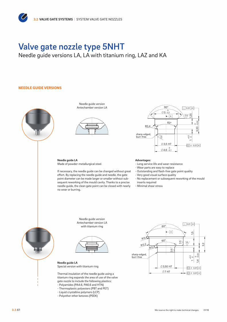
NEEDLE GUIDE VERSIONS
Needle guide version Antechamber version LA
Needle guide version Antechamber version LA
with titanium ring
Valve gate nozzle type 5NHTNeedle guide versions LA, LA with titanium ring, LAZ and KA
Needle guide LAMade of powder-metallurgical steel
If necessary, the needle guide can be changed without great effort. By replacing the needle guide and needle, the gate point diameter can be made larger or smaller without sub-sequent reworking of the mould cavity. Thanks to a precise needle guide, the clean gate point can be closed with nearly no wear or burring.
Advantages:- Long service life and wear-resistance- Wear parts are easy to replace- Outstanding and flash-free gate point quality- Very good visual surface quality- No replacement or subsequent reworking of the mould
inserts required- Minimal shear stress
Needle guide LASpecial version with titanium ring
Thermal insulation of the needle guide using a titanium ring expands the area of use of the valve gate nozzle to include the following plastics:- Polyamides (PA4.6, PA6.6 and HTN)- Thermoplastic polyesters (PBT and PET)- Liquid crystalline polymers (LCP)- Polyether ether ketones (PEEK)

70°
90°
5 -00,1
3,2
0 -0 0,
02
S7 H6
4,60 -00,1
0,58
0+0,0
5t6
±0,0
5
Detail X: Ausführung NadelführungVorkammer - Ausführung LAZ
R0,4
0,4
0,4
0.01 A
0.01 A
A
Ausführung NadelführungVorkammer - Ausführung LAZ
sharp-edged, burr-free
D ++
0,0070,003
0,3
-0 0,1
45°
R0,5
Detail Y:Ausführung Nadelführung Vorkammer - Ausführung KA
1,6
ground0,2
0,005 A
Ausführung NadelführungVorkammer - Ausführung KA
sharp-edged, burr-free
D ++
0,0070,003
0,3
-0 0,1
45°
R0,5
Detail Y:Ausführung Nadelführung Vorkammer - Ausführung KA
1,6
ground0,2
0,005 A
Ausführung NadelführungVorkammer - Ausführung KA
sharp-edged, burr-free
70°
90°
5 -00,1
3,2
0 -0 0,
02
S7 H6
4,60 -00,1
0,58
0+0,0
5t6
±0,0
5
Detail X: Ausführung NadelführungVorkammer - Ausführung LAZ
R0,4
0,4
0,4
0.01 A
0.01 A
A
Ausführung NadelführungVorkammer - Ausführung LAZ
sharp-edged, burr-free
3.2.6101/18 We reserve the right to make technical changes.
Valve gate nozzle type 5NHT
Needle guide version Antechamber version LAZ
Needle guide version Antechamber version KA
Installation dimensions of needle guide version LAZ
ØD ØS7 t60.8 2.2 0.911.0 2.4 1.051.2 2.6 1.201.4 2.8 1.34
Needle guide LAZMade of powder-metallurgical steel
If necessary, the needle guide can be changed without great effort. By replacing the needle guide and needle, the gate point diameter can be made larger or smaller without subsequent reworking of the mould cavity. Thanks to a precise needle guide, the clean gate point can be closed with nearly no wear or burring. Needle guide type LAZ has a tapered shape with a smaller contact surface which creates a smaller impression. This version is suitable for items with a minimal wall thickness and part geometries not permitting a larger impression.
Advantages:- Long service life and wear-resistance- Wear parts are easy to replace- Outstanding and flash-free gate point quality- Very good visual surface quality- No replacement or subsequent reworking of
the mould inserts required- Minimal shear stress
Needle guide KAThis is used when a second marking on the part is not permissible.
When selecting the material to be used, the needle hardness of 64 ±2 HRC is to be taken into account!

TECHNICAL DATA
6NHT
Needle Ød 3 mm
Melt channel Ød 6 mm
Gate point Ød 0.8, 1.0, 1.2 or 1.4 mm
Operating voltage 230 VAC*
Nominal length of the nozzle (L) in mm
50 60 80 100 120 150 200
Contact us for other nozzle lengths!
*Volts alternating current
available on request
NOTE
Power connector CMT and thermocouple connector CMLK are to be ordered separately.
3.2 VALVE GATE SYSTEMS | SYSTEM VALVE GATE NOZZLES
3.2.70 We reserve the right to make technical changes. 01/18
Valve gate nozzle type 6NHTSystem nozzle with conventional heating element, screwed to the manifold
WEBCODE32050
38
L
+ 0,02
0
min
. 35
m
in. 3
0
6,0
("K
")
1Shut-o� needle
VH
Clamping plate
Nozzle holding plate
Manifold
Cavity plate
Thermocouple connectorCMLK
PowerconnectorCMT
120
20
60
45° 45°
SW
28
27 H7
26 H7
R2 90°
35
0
,5 x
45
5 + 0,
10
L + 0,
020
26,5 +
0,40
R8
45°
45°
10,
9 -0 0,
2
1,2
-0 0,
1
Geschlossene Düse mit Nadelführung- Vorkammer Ausführung KA
1,6
1,6
6,3
6,3
0,02 A
0,02 A
A
26 H7
90°R2
R2
26,5 0+0,4
27 H7
50+0
,1
0,5x
45°
45°
35
L0+0
,02
45°
10,6 0+0,1
10,9
-0,20
Geschlossene Düse mit Nadelführung- Vorkammer - Ausführungen LA
1,6
1,6
6,3
6,3
0.02 A
0.02 A
A
„X“
3.2.7001/18 We reserve the right to make technical changes.
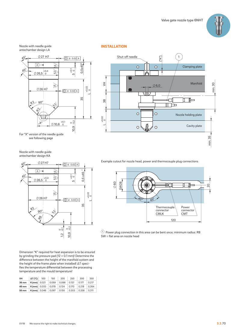
Valve gate nozzle type 6NHT
Example cutout for nozzle head, power and thermocouple plug connections
INSTALLATION
Nozzle with needle guide antechamber design KA
Nozzle with needle guide antechamber design LA
1 Power plug connection in this area can be bent once; minimum radius: R8SW = flat area on nozzle head
VH ∆T (°C) 100 150 200 250 300 350
36 mm K (mm) 0.021 0.059 0.098 0.137 0.177 0.217
46 mm K (mm) 0.033 0.078 0.124 0.170 0.218 0.264
56 mm K (mm) 0.046 0.097 0.150 0.203 0.258 0.311
Dimension “K” required for heat expansion is to be ensured by grinding the pressure pad (12 + 0.1 mm)! Determine the difference between the height of the manifold system and the height of the frame plate when installed! ∆T speci-fies the temperature differential between the processing temperature and the mould temperature!
For “X” version of the needle guide see following page

3,50 H7
7 H7
1,4
-0,0
20
3,2
R0,2R 0,4
R0,4
60°
60°
10+0
,11,
5
Detail X: Ausführung NadelführungVorkammer - Ausführung LAmit Titanring
0.4
0.4 1,6
0,01 A
0,01 A
0,01 A
A
Ausführung NadelführungVorkammer - Ausführung LAmit Titanring
sharp-edged, burr-free
3,20
-0,0
20
3,5 H7
4,6 -0,10
60°
5 -0,10
90°
10+0
,11,
25
Detail X: Ausführung Nadelführung Vorkammer - Ausführung LA
R0,4
0.4
0,4
0.01 A
0.01 A
A
Ausführung NadelführungVorkammer - Ausführung LA
sharp-edged, burr-free 3,
20-0
,02
0
3,5 H7
4,6 -0,10
60°
5 -0,10
90°
10+0
,11,
25
Detail X: Ausführung Nadelführung Vorkammer - Ausführung LA
R0,4
0.4
0,4
0.01 A
0.01 A
A
Ausführung NadelführungVorkammer - Ausführung LA
sharp-edged, burr-free
3,50 H7
7 H7
1,4
-0,0
20
3,2
R0,2R 0,4
R0,4
60°
60°
10+0
,11,
5
Detail X: Ausführung NadelführungVorkammer - Ausführung LAmit Titanring
0.4
0.4 1,6
0,01 A
0,01 A
0,01 A
A
Ausführung NadelführungVorkammer - Ausführung LAmit Titanring
sharp-edged, burr-free
3.2 VALVE GATE SYSTEMS | SYSTEM VALVE GATE NOZZLES
3.2.71 We reserve the right to make technical changes. 01/18
NEEDLE GUIDE VERSIONS
Needle guide version Antechamber version LA
Needle guide version Antechamber version LA
with titanium ring
Valve gate nozzle type 6NHTNeedle guide versions LA, LA with titanium ring, LAZ and KA
Needle guide LAMade of powder-metallurgical steel
If necessary, the needle guide can be changed without great effort. By replacing the needle guide and needle, the gate point diameter can be made larger or smaller without sub-sequent reworking of the mould cavity. Thanks to a precise needle guide, the clean gate point can be closed with nearly no wear or burring.
Advantages:- Long service life and wear-resistance- Wear parts are easy to replace- Outstanding and flash-free gate point quality- Very good visual surface quality- No replacement or subsequent reworking of the mould
inserts required- Minimal shear stress
Needle guide LASpecial version with titanium ring
Thermal insulation of the needle guide using a titanium ring expands the area of use of the valve gate nozzle to include the following plastics:- Polyamides (PA4.6, PA6.6 and HTN)- Thermoplastic polyesters (PBT and PET)- Liquid crystalline polymers (LCP)- Polyether ether ketones (PEEK)

70°
90°
5 -00,1
3,2
0 -0 0,
02
S7 H6
4,60 -00,1
0,58
0+0,0
5t6
±0,0
5
Detail X: Ausführung NadelführungVorkammer - Ausführung LAZ
R0,4
0,4
0,4
0.01 A
0.01 A
A
Ausführung NadelführungVorkammer - Ausführung LAZ
sharp-edged, burr-free
D ++
0,0070,003
0,3
-0 0,1
R0,5
45°
Detail Y: Ausführung Nadelführung Vorkammer - Ausführung KA
1,6
ground0,2
0,005 A
Ausführung NadelführungVorkammer - Ausführung KA
sharp-edged, burr-free
D ++
0,0070,003
0,3
-0 0,1
R0,5
45°
Detail Y: Ausführung Nadelführung Vorkammer - Ausführung KA
1,6
ground0,2
0,005 A
Ausführung NadelführungVorkammer - Ausführung KA
sharp-edged, burr-free
70°
90°
5 -00,1
3,2
0 -0 0,
02
S7 H6
4,60 -00,1
0,58
0+0,0
5t6
±0,0
5
Detail X: Ausführung NadelführungVorkammer - Ausführung LAZ
R0,4
0,4
0,4
0.01 A
0.01 A
A
Ausführung NadelführungVorkammer - Ausführung LAZ
sharp-edged, burr-free
3.2.7101/18 We reserve the right to make technical changes.
Valve gate nozzle type 6NHT
Needle guide version Antechamber version LAZ
Needle guide version Antechamber version KA
Installation dimensions of needle guide version LAZ
ØD ØS7 t60.8 2.2 0.911.0 2.4 1.051.2 2.6 1.201.4 2.8 1.34
Needle guide LAZMade of powder-metallurgical steel
If necessary, the needle guide can be changed without great effort. By replacing the needle guide and needle, the gate point diameter can be made larger or smaller without subsequent reworking of the mould cavity. Thanks to a precise needle guide, the clean gate point can be closed with nearly no wear or burring. Needle guide type LAZ has a tapered shape with a smaller contact surface which creates a smaller impression. This version is suitable for items with a minimal wall thickness and part geometries not permitting a larger impression.
Advantages:- Long service life and wear-resistance- Wear parts are easy to replace- Outstanding and flash-free gate point quality- Very good visual surface quality- No replacement or subsequent reworking of
the mould inserts required- Minimal shear stress
Needle guide KAThis is used when a second marking on the part is not permissible.
When selecting the material to be used, the needle hardness of 64 ±2 HRC is to be taken into account!

TECHNICAL DATA
8NHT
Needle Ød 3 mm
Melt channel Ød 7.5 mm
Gate point Ød 1.6, 2.0 or 2.5 mm
Operating voltage 230 VAC*
Nominal length of the nozzle (L) in mm
50 60 80 100 120 150 200 250
Contact us for other nozzle lengths!
*Volts alternating current
available on request
NOTE
Power connector CMT and thermocouple connector CMLK are to be ordered separately.
3.2 VALVE GATE SYSTEMS | SYSTEM VALVE GATE NOZZLES
3.2.80 We reserve the right to make technical changes. 01/18
Valve gate nozzle type 8NHTSystem nozzle with conventional heating element, screwed to the manifold
WEBCODE32060

38
L
+ 0,02
0
min
. 35
7,5
min
. 20
("K
")
1Shut-o� needle
VH
Clamping plate
Manifold
Nozzle holding plate
Cavity plate
Thermocouple connectorCMLK
PowerconnectorCMT
80
192
11
17
45° 45°
SW
46
27 H7
0,5x
45°
50+0
,1
26,5 0+0,4
26 H7
R290°
35
L0+0
,02
R8
45°
45°
1,20
-0,10
10,9
-0,20
Geschlossene Düse mit Nadelführung- Vorkammer - Ausführung KA
1,6
1,6
6,3
6,3
0.02 A
0.02 A
A
27 H7
0,5x
45°
50+0
,1
26,5 0+0,4
R2
R2
35
L0+0
,02
26 H7
90°
45°
45°
10,9
-0,2012,6 0
+0,1
Geschlossene Düse mit Nadelführung- Vorkammer - Ausführungen LA
6,3
6,3
1,6
1,6
0,02 A
0,02 A
A
„X“
3.2.8001/18 We reserve the right to make technical changes.
Valve gate nozzle type 8NHT
Example cutout for nozzle head, power and thermocouple plug connections
INSTALLATION
Nozzle with needle guide antechamber design KA
Nozzle with needle guide antechamber design LA
1 Power and thermocouple plug connections in this area can be bent once; minimum radius: R8
SW = flat area on nozzle head
VH ∆T (°C) 100 150 200 250 300 350
36 mm K (mm) 0.021 0.059 0.098 0.137 0.177 0.217
46 mm K (mm) 0.033 0.078 0.124 0.170 0.218 0.264
56 mm K (mm) 0.046 0.097 0.150 0.203 0.258 0.311
Dimension “K” required for heat expansion is to be ensured by grinding the pressure pad (12 + 0.1 mm)! Determine the difference between the height of the manifold system and the height of the frame plate when installed! ∆T speci-fies the temperature differential between the processing temperature and the mould temperature!
For “X” version of the needle guide see following page

4,2
- 0,0
20
1,2
±0,0
5
2,2
5 H7
7
7,4 -0,10
90°
60°
Detail X: Ausführung NadelführungVorkammer - Ausführung LA
R0,4
0,4
0,4
0,01 A
0.01 A
A
Ausführung NadelführungVorkammer - Ausführug LA
sharp-edged, burr-free
4,2
-0,0
20
1,2
±0,0
5
2,2
5 H7
7
7,4 -0,10
90°
60°
Detail X: Ausführung NadelführungVorkammer - Ausführung LA
R0,4
0,4
0,4
0,01 A
0.01 A
A
Ausführung NadelführungVorkammer - Ausführug LA
sharp-edged, burr-free
60°
60°
R0,4
R0,2
R0,4
5 H7
10 H7
4,2
2,4
0 -0 0,
02
1,2
±0,0
51,
5
Detail X: Ausführung NadelführungVorkammer - Ausführung LAmit Titanring
0,4
0,4
1,6
0,01 A
0,01 A0.01 A
A
Ausführung NadelführungVorkammer - Ausführug LAmit Titanring
sharp-edged, burr-free
60°
60°
R0,4
R0,2
R0,4
5 H7
10 H7
4,2
2,4
0 -0 0,
02
1,2
±0,0
51,
5
Detail X: Ausführung NadelführungVorkammer - Ausführung LAmit Titanring
0,4
0,4
1,6
0,01 A
0,01 A0.01 A
A
Ausführung NadelführungVorkammer - Ausführug LAmit Titanring
sharp-edged, burr-free
3.2 VALVE GATE SYSTEMS | SYSTEM VALVE GATE NOZZLES
3.2.81 We reserve the right to make technical changes. 01/18
NEEDLE GUIDE VERSIONS
Needle guide version Antechamber version LA
Needle guide version Antechamber version LA
with titanium ring
Valve gate nozzle type 8NHTNeedle guide versions LA, LA with titanium ring, LAZ and KA
Needle guide LAMade of powder-metallurgical steel
If necessary, the needle guide can be changed without great effort. By replacing the needle guide and needle, the gate point diameter can be made larger or smaller without sub-sequent reworking of the mould cavity. Thanks to a precise needle guide, the clean gate point can be closed with nearly no wear or burring.
Advantages:- Long service life and wear-resistance- Wear parts are easy to replace- Outstanding and flash-free gate point quality- Very good visual surface quality- No replacement or subsequent reworking of
the mould inserts required- Minimal shear stress
Needle guide LASpecial version with titanium ring
Thermal insulation of the needle guide using a titanium ring expands the area of use of the valve gate nozzle to include the following plastics:- Polyamides (PA4.6, PA6.6 and HTN)- Thermoplastic polyesters (PBT and PET)- Liquid crystalline polymers (LCP)- Polyether ether ketones (PEEK)

4,20
-0,0
20
7,4 -0,10
7 -0,10
S7 H6
70°
90°
t6
t5
±0,0
5
±0,0
5
Detail X: Ausführung NadelführungVorkammer - Ausführung LAZ
R0,4
0,4
0,4
0.01 A
0.01 A
A
Ausführung NadelführungVorkammer - Ausführug LAZ
sharp-edged, burr-free
4,20
-0,0
20
7,4 -0,10
7 -0,10
S7 H6
70°
90°
t6
t5
±0,0
5
±0,0
5
Detail X: Ausführung NadelführungVorkammer - Ausführung LAZ
R0,4
0,4
0,4
0.01 A
0.01 A
A
Ausführung NadelführungVorkammer - Ausführug LAZ
sharp-edged, burr-free
45°
R0,5
0,5
-0 0,1
D ++
0,0070,003
Detail Y: Ausführung NadelführungVorkammer - Ausführung KA
1,6
ground0,2
0,005 A
A
Ausführung NadelführungVorkammer - Ausführug KA
sharp-edged, burr-free
45°
R0,5
0,5
-0 0,1
D ++
0,0070,003
Detail Y: Ausführung NadelführungVorkammer - Ausführung KA
1,6
ground0,2
0,005 A
A
Ausführung NadelführungVorkammer - Ausführug KA
sharp-edged, burr-free
3.2.8101/18 We reserve the right to make technical changes.
Valve gate nozzle type 8NHT
Needle guide version Antechamber version LAZ
Needle guide version Antechamber version KA
Installation dimensions of needle guide version LAZ
ØD ØS7 t5 t61.6 3.0 0.63 0.772.0 3.5 0.63 1.072.5 4.0 0.58 1.43
Needle guide LAZMade of powder-metallurgical steel
If necessary, the needle guide can be changed without great effort. By replacing the needle guide and needle, the gate point diameter can be made larger or smaller without subsequent reworking of the mould cavity. Thanks to a precise needle guide, the clean gate point can be closed with nearly no wear or burring. Needle guide type LAZ has a tapered shape with a smaller contact surface which creates a smaller impression. This version is suitable for items with a minimal wall thickness and part geometries not permitting a larger impression.
Advantages:- Long service life and wear-resistance- Wear parts are easy to replace- Outstanding and flash-free gate point quality- Very good visual surface quality- No replacement or subsequent reworking of
the mould inserts required- Minimal shear stress
Needle guide KAThis is used when a second marking on the part is not permissible.
When selecting the material to be used, the needle hardness of 64 ±2 HRC is to be taken into account!

TECHNICAL DATA
10NHT
Needle Ød 3 mm
Melt channel Ød 10 mm
Gate point Ød 2.0 or 2.5 mm
Needle Ød 5 mm
Melt channel Ød 10 mm
Gate point Ød 3.0, 3.5 or 4.0 mm
Operating voltage 230 VAC*
Nominal length of the nozzle (L) in mm
60 80 100 120 150 200 250
Contact us for other nozzle lengths!
*Volts alternating current
available on request
NOTE
Power connector CMT and thermocouple connector CMLK are to be ordered separately.
3.2 VALVE GATE SYSTEMS | SYSTEM VALVE GATE NOZZLES
3.2.90 We reserve the right to make technical changes. 11/20
Valve gate nozzle type 10NHTSystem nozzle with conventional heating element, screwed to the manifold
WEBCODE32070

38
L
+ 0,02
0
min
. 38
m
in. 2
0 10
("K
")
1Shut-o� needle
VH
Clamping plate
Manifold
Nozzle holding plate
Cavity plate
Thermocouple connectorCMLK
PowerconnectorCMT
80
11
17
192
45° 45°
SW
46
Geschlossene Düse mit Nadelführung- Vorkammer - Ausführung KA
33 H7
0,5x
45°
100+0
,1
32,5 0+0,4
32 H7
R290°
38
L0+0
,02
45°
45°
R8
13,9
-0,20
1,2
-0 0,
1
1.6
6.3
6.3
1.6
0.02 A
0.02 A
A
R0,4
R 2
32 H7
20 0+0,1
380,
5x45
°
100+0
,1
32,5 0+0,4
33 H7
L0+0
,02
90°
45°
45°
13,9
-0,20
Geschlossene Düse mit Nadelführung- Vorkammer - Ausführungen LA
1.6
1.6
6.3
6.3
0.02 A
0.02 A
A
„X“
3.2.9011/20 We reserve the right to make technical changes.
Valve gate nozzle type 10NHT
Example cutout for nozzle head, power and thermocouple plug connections
INSTALLATION
Nozzle with needle guide antechamber design KA
Nozzle with needle guide antechamber design LA
1 Power and thermocouple plug connections in this area can be bent once; minimum radius: R8
SW = flat area on nozzle head
VH ∆T (°C) 100 150 200 250 300 350
36 mm K (mm) 0.021 0.059 0.098 0.137 0.177 0.217
46 mm K (mm) 0.033 0.078 0.124 0.170 0.218 0.264
56 mm K (mm) 0.046 0.097 0.150 0.203 0.258 0.311
Dimension “K” required for heat expansion is to be ensured by grinding the pressure pad (12 + 0.1 mm)! Determine the difference between the height of the manifold system and the height of the frame plate when installed! ∆T speci-fies the temperature differential between the processing temperature and the mould temperature!
For “X” version of the needle guide see following page

10,8 -0,10
90°
R0,8
R1,2
60°
2,6
4,80
-0,0
20
6,50 H7
10,4 -0,10
1,32
±0,0
5
Detail X: Ausführung NadelführungVorkammer - Ausführung LA
0.4
0.4
0.01 A
0.01 A
A
Ausführung NadelführungVorkammer - Ausführung LA
sharp-edged, burr-free
10,8 -0,10
90°
R0,8
R1,2
60°
2,6
4,80
-0,0
20
6,50 H7
10,4 -0,10
1,32
±0,0
5
Detail X: Ausführung NadelführungVorkammer - Ausführung LA
0.4
0.4
0.01 A
0.01 A
A
Ausführung NadelführungVorkammer - Ausführung LA
sharp-edged, burr-free
6,50 H7
14,50 H7
R1,2R0,2R0,4
60°
2,20
-0,0
20
4,8 60°
1,32
±0,0
52,
3
Detail X: Ausführung NadelführungVorkammer - Ausführung LAmit Titanring
0.4 0.
4
1.6
0.01 A
0.01 A
0.01 A
A
Ausführung NadelführungVorkammer - Ausführung LAmit Titanring
sharp-edged, burr-free
6,50 H7
14,50 H7
R1,2R0,2R0,4
60°
2,20
-0,0
20
4,8 60°
1,32
±0,0
52,
3Detail X: Ausführung NadelführungVorkammer - Ausführung LAmit Titanring
0.4 0.
4
1.6
0.01 A
0.01 A
0.01 A
A
Ausführung NadelführungVorkammer - Ausführung LAmit Titanring
sharp-edged, burr-free
3.2 VALVE GATE SYSTEMS | SYSTEM VALVE GATE NOZZLES
3.2.91 We reserve the right to make technical changes. 01/18
NEEDLE GUIDE VERSIONS
Needle guide version Antechamber version LA
Needle guide version Antechamber version LA
with titanium ring
Valve gate nozzle type 10NHTNeedle guide versions LA, LA with titanium ring and KA
Needle guide LAMade of powder-metallurgical steel
If necessary, the needle guide can be changed without great effort. By replacing the needle guide and needle, the gate point diameter can be made larger or smaller without sub-sequent reworking of the mould cavity. Thanks to a precise needle guide, the clean gate point can be closed with nearly no wear or burring.
Advantages:- Long service life and wear-resistance- Wear parts are easy to replace- Outstanding and flash-free gate point quality- Very good visual surface quality- No replacement or subsequent reworking of
the mould inserts required- Minimal shear stress
Needle guide LASpecial version with titanium ring
Thermal insulation of the needle guide using a titanium ring expands the area of use of the valve gate nozzle to include the following plastics:- Polyamides (PA4.6, PA6.6 and HTN)- Thermoplastic polyesters (PBT and PET)- Liquid crystalline polymers (LCP)- Polyether ether ketones (PEEK)

45°
R0,5
0,5
-0 0,1
D ++
0,0070,003
Detail Y: Ausführung NadelführungVorkammer - Ausführung KA
ground0,2
0,005 A
A
Ausführung NadelführungVorkammer - Ausführung KA
sharp-edged, burr-free
45°
R0,5
0,5
-0 0,1
D ++
0,0070,003
Detail Y: Ausführung NadelführungVorkammer - Ausführung KA
ground0,2
0,005 A
A
Ausführung NadelführungVorkammer - Ausführung KA
sharp-edged, burr-free
3.2.9101/18 We reserve the right to make technical changes.
Valve gate nozzle type 10NHT
Needle guide version Antechamber version KA
Needle guide KAThis is used when a second marking on the part is not permissible.
When selecting the material to be used, the needle hardness of 64 ±2 HRC is to be taken into account!

TECHNICAL DATA
12NHT
Needle Ød 5 mm
Melt channel Ød 12 mm
Gate point Ød 3.0, 3.5 or 4.0 mm
Operating voltage 230 VAC*
Nominal length of the nozzle (L) in mm
60 80 100 120 150 200 250
Contact us for other nozzle lengths!
*Volts alternating current
available on request
NOTE
Power connector CMT and thermocouple connector CMLK are to be ordered separately.
3.2 VALVE GATE SYSTEMS | SYSTEM VALVE GATE NOZZLES
3.2.100 We reserve the right to make technical changes. 01/18
Valve gate nozzle type 12NHTSystem nozzle with conventional heating element, screwed to the manifold
WEBCODE32080
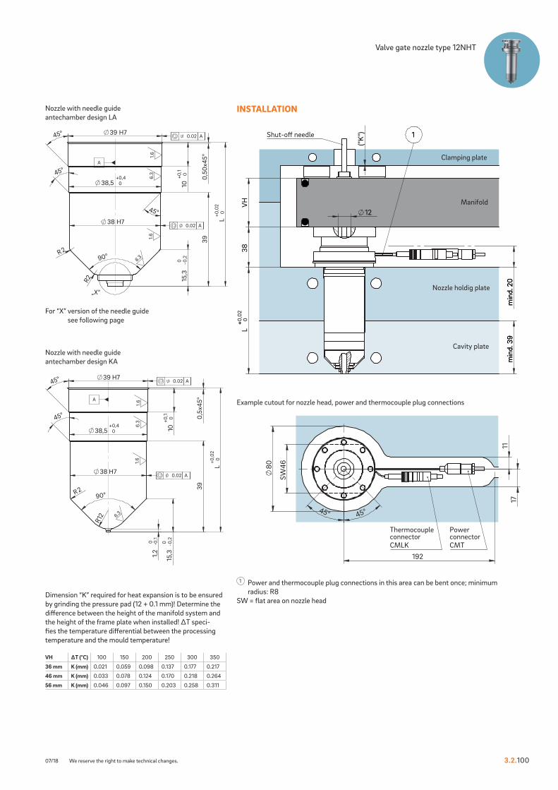
+
min
d. 3
9
min
d. 2
0
1
38
L
+ 0,02
0
min
d. 3
9
VH
min
d. 2
0
12
("K
")
Clamping plate
Manifold
Nozzle holdig plate
Cavity plate
1Shut-o� needle
Thermocouple connectorCMLK
PowerconnectorCMT
80
11
17
192
45° 45°
SW
46
Geschlossene Düse mit Nadelführung- Vorkammer - Ausführung KA
39 H7
0,5x
45°
100+0
,1
38,5 0+0,4
38 H7
R290°
39
L0+0
,02
45°
45°
R12
15,3
-0,20
1,2
-0 0,
1
1.6
6.3
6.3
1.6
0.02 A
0.02 A
A
R2
390,
50x4
5°
100+0
,1
L0+0
,02
38,5 0+0,4
38 H7
45°
39 H7
90°
R2
45°
45°
15,3
-0,20
Geschlossene Düse mit Nadelführung- Vorkammer - Ausführungen LA
1.6
1.6
6.3
6.3
0.02 A
0.02 A
A
„X“
3.2.10007/18 We reserve the right to make technical changes.
Valve gate nozzle type 12NHT
Example cutout for nozzle head, power and thermocouple plug connections
INSTALLATION
Nozzle with needle guide antechamber design KA
Nozzle with needle guide antechamber design LA
1 Power and thermocouple plug connections in this area can be bent once; minimum radius: R8
SW = flat area on nozzle head
VH ∆T (°C) 100 150 200 250 300 350
36 mm K (mm) 0.021 0.059 0.098 0.137 0.177 0.217
46 mm K (mm) 0.033 0.078 0.124 0.170 0.218 0.264
56 mm K (mm) 0.046 0.097 0.150 0.203 0.258 0.311
Dimension “K” required for heat expansion is to be ensured by grinding the pressure pad (12 + 0.1 mm)! Determine the difference between the height of the manifold system and the height of the frame plate when installed! ∆T speci-fies the temperature differential between the processing temperature and the mould temperature!
For “X” version of the needle guide see following page

10,8 -0,10
90°
R0,8
R1,2
60°
2,6
4,80
-0,0
20
6,50 H7
10,4 -0,10
1,32
±0,0
5
Detail X: Ausführung NadelführungVorkammer - Ausführung LA
0.4
0.4
0.01 A
0.01 A
A
Ausführung NadelführungVorkammer - Ausführung LA
sharp-edged, burr-free
10,8 -0,10
90°
R0,8
R1,2
60°
2,6
4,80
-0,0
20
6,50 H7
10,4 -0,10
1,32
±0,0
5
Detail X: Ausführung NadelführungVorkammer - Ausführung LA
0.4
0.4
0.01 A
0.01 A
A
Ausführung NadelführungVorkammer - Ausführung LA
sharp-edged, burr-free
6,50 H7
14,50 H7
R1,2R0,2R0,4
60°
2,20
-0,0
20
4,8 60°
1,32
±0,0
52,
3
Detail X: Ausführung NadelführungVorkammer - Ausführung LAmit Titanring
0.4 0.
4
1.6
0.01 A
0.01 A
0.01 A
A
Ausführung NadelführungVorkammer - Ausführung LAmit Titanring
sharp-edged, burr-free
6,50 H7
14,50 H7
R1,2R0,2R0,4
60°
2,20
-0,0
20
4,8 60°
1,32
±0,0
52,
3Detail X: Ausführung NadelführungVorkammer - Ausführung LAmit Titanring
0.4 0.
4
1.6
0.01 A
0.01 A
0.01 A
A
Ausführung NadelführungVorkammer - Ausführung LAmit Titanring
sharp-edged, burr-free
3.2 VALVE GATE SYSTEMS | SYSTEM VALVE GATE NOZZLES
3.2.101 We reserve the right to make technical changes. 01/18
NEEDLE GUIDE VERSIONS
Needle guide version Antechamber version LA
Needle guide version Antechamber version LA
with titanium ring
Valve gate nozzle type 12NHTNeedle guide versions LA, LA with titanium ring and KA
Needle guide LAMade of powder-metallurgical steel
If necessary, the needle guide can be changed without great effort. By replacing the needle guide and needle, the gate point diameter can be made larger or smaller without sub-sequent reworking of the mould cavity. Thanks to a precise needle guide, the clean gate point can be closed with nearly no wear or burring.
Advantages:- Long service life and wear-resistance- Wear parts are easy to replace- Outstanding and flash-free gate point quality- Very good visual surface quality- No replacement or subsequent reworking of
the mould inserts required- Minimal shear stress
Needle guide LASpecial version with titanium ring
Thermal insulation of the needle guide using a titanium ring expands the area of use of the valve gate nozzle to include the following plastics:- Polyamides (PA4.6, PA6.6 and HTN)- Thermoplastic polyesters (PBT and PET)- Liquid crystalline polymers (LCP)- Polyether ether ketones (PEEK)

45°
R0,5
0,5
-0 0,1
D ++
0,0070,003
Detail Y: Ausführung NadelführungVorkammer - Ausführung KA
ground0,2
0,005 A
A
Ausführung NadelführungVorkammer - Ausführung KA
sharp-edged, burr-free
45°
R0,5
0,5
-0 0,1
D ++
0,0070,003
Detail Y: Ausführung NadelführungVorkammer - Ausführung KA
ground0,2
0,005 A
A
Ausführung NadelführungVorkammer - Ausführung KA
sharp-edged, burr-free
3.2.10101/18 We reserve the right to make technical changes.
Valve gate nozzle type 12NHT
Needle guide version Antechamber version KA
Needle guide KAThis is used when a second marking on the part is not permissible.
When selecting the material to be used, the needle hardness of 64 ±2 HRC is to be taken into account!

TECHNICAL DATA
5NMT
Needle Ød 3 mm
Melt channel Ød 4.8 mm
Gate point Ød 0.8, 1.0, 1.2 or 1.4 mm
Operating voltage 230 VAC*
Nominal length of the nozzle (L) in mm
50 60 80 100 120 150
Contact us for other nozzle lengths!
*Volts alternating current
available on request
3.2 VALVE GATE SYSTEMS | SYSTEM VALVE GATE NOZZLES
3.2.110 We reserve the right to make technical changes. 01/18
Valve gate nozzle type 5NMTSystem nozzle with conventional heating element, for minimal spacing, not screwed to the manifold
WEBCODE32090

38
L
+ 0,02
0
min
. 32
m
in. 3
0
4,8
("K
")
1Shut-o� needle
VH
Clamping plate
Nozzle holding plate
Power connection: Permanent, incl. 2 m cable (flexible)
Thermocouple plug connection: Permanent, incl. 2 m cable (flexible)
Manifold
Cavity plate
55
108 1
7
SW
23,5
23 H7
22 H7
R2 90°
32
0
,5 x
45
5 + 0,
10
L + 0,
020
22,5 +
0,40
R8
8,9
-0 0,2
1,2
-0 0,
1
Geschlossene Düse mit Nadelführung- Vorkammer - Ausführung KA
1,6
6,3
6,3
1,6
0,02 A
0,02 A
A
22 H7
90°R2
R2
22,5 0+0,4
23 H7
50+0
,1
0,5x
45°
45°
32
L0+0
,02
45°
10,6 0+0,1
8,9
-0,20
Geschlossene Düse mit Nadelführung- Vorkammer - Ausführung LA
1,6
6,3
6,3
1,6
0.02 A
0.02 A
A
„X“
3.2.11001/18 We reserve the right to make technical changes.
Valve gate nozzle type 5NMT
Example cutout for nozzle head, power and thermocouple plug connections
INSTALLATION
Nozzle with needle guide antechamber design KA
Nozzle with needle guide antechamber design LA
1 Power and thermocouple plug connections in this area can be bent once; minimum radius: R8
SW = flat area on nozzle head
VH ∆T (°C) 100 150 200 250 300 350
36 mm K (mm) 0.021 0.059 0.098 0.137 0.177 0.217
46 mm K (mm) 0.033 0.078 0.124 0.170 0.218 0.264
56 mm K (mm) 0.046 0.097 0.150 0.203 0.258 0.311
Dimension “K” required for heat expansion is to be ensured by grinding the pressure pad (12 + 0.1 mm)! Determine the difference between the height of the manifold system and the height of the frame plate when installed! ∆T speci-fies the temperature differential between the processing temperature and the mould temperature!
For “X” version of the needle guide see following page

3,20
- 0,0
20
3,50 H7
4,6 -0,10
60°
5 -0,10
90°
10+0
,11,
25
R0,4
Detail X: Ausführung NadelführungVorkammer - Ausführung LA
0.4
0.4
0.01 A
0.01 A
A
Ausführung NadelführungVorkammer - Ausführung LA
sharp-edged, burr-free 3,
20-0
,02
0
3,50 H7
4,6 -0,10
60°
5 -0,10
90°
10+0
,11,
25
R0,4
Detail X: Ausführung NadelführungVorkammer - Ausführung LA
0.4
0.4
0.01 A
0.01 A
A
Ausführung NadelführungVorkammer - Ausführung LA
sharp-edged, burr-free
3,50 H7
7 H7
1,4
-0,0
20
3,20
R0,2R0,4
R0,4
60°
60°
10+0
,11,
5
Detail X: Ausführung NadelführungVorkammer - Ausführung LAmit Titanring
0.4
0.4
1,6
0,01 A
0,01 A
0,01 A
A
Ausführung NadelführungVorkammer - Ausführung LAmit Titanring
sharp-edged, burr-free
3,50 H7
7 H7
1,4
-0,0
20
3,20
R0,2R0,4
R0,4
60°
60°
10+0
,11,
5
Detail X: Ausführung NadelführungVorkammer - Ausführung LAmit Titanring
0.4
0.4
1,6
0,01 A
0,01 A
0,01 A
A
Ausführung NadelführungVorkammer - Ausführung LAmit Titanring
sharp-edged, burr-free
3.2 VALVE GATE SYSTEMS | SYSTEM VALVE GATE NOZZLES
3.2.111 We reserve the right to make technical changes. 01/18
NEEDLE GUIDE VERSIONS
Needle guide version Antechamber version LA
Needle guide version Antechamber version LA
with titanium ring
Valve gate nozzle type 5NMTNeedle guide versions LA, LA with titanium ring, LAZ and KA
Needle guide LAMade of powder-metallurgical steel
If necessary, the needle guide can be changed without great effort. By replacing the needle guide and needle, the gate point diameter can be made larger or smaller without sub-sequent reworking of the mould cavity. Thanks to a precise needle guide, the clean gate point can be closed with nearly no wear or burring.
Advantages:- Long service life and wear-resistance- Wear parts are easy to replace- Outstanding and flash-free gate point quality- Very good visual surface quality- No replacement or subsequent reworking of
the mould inserts required- Minimal shear stress
Needle guide LASpecial version with titanium ring
Thermal insulation of the needle guide using a titanium ring expands the area of use of the valve gate nozzle to include the following plastics:- Polyamides (PA4.6, PA6.6 and HTN)- Thermoplastic polyesters (PBT and PET)- Liquid crystalline polymers (LCP)- Polyether ether ketones (PEEK)

90°
5 -00,1
70°
4,6 -00,1
S7 H6
3,2
0 -0 0,
02
0,58
0+0,0
5t6
±0,0
5
R0,4
Detail X: Ausführung NadelführungVorkammer - Ausführung LAZ
0.4
0.4
0.01 A
0,01 A
A
Ausführung NadelführungVorkammer - Ausführung LAZ
sharp-edged, burr-free
D ++
0,0070,003
0,3
-0 0,1
R0,5
45°
Detail Y: Ausführung NadelführungVorkammer - Ausführung KA
1,6
ground0,2
0,005 A
Ausführung NadelführungVorkammer - Ausführung KA
sharp-edged, burr-free
D ++
0,0070,003
0,3
-0 0,1
R0,5
45°
Detail Y: Ausführung NadelführungVorkammer - Ausführung KA
1,6
ground0,2
0,005 A
Ausführung NadelführungVorkammer - Ausführung KA
sharp-edged, burr-free
90°
5 -00,1
70°
4,6 -00,1
S7 H6
3,2
0 -0 0,
02
0,58
0+0,0
5t6
±0,0
5
R0,4
Detail X: Ausführung NadelführungVorkammer - Ausführung LAZ
0.4
0.4
0.01 A
0,01 A
A
Ausführung NadelführungVorkammer - Ausführung LAZ
sharp-edged, burr-free
3.2.11101/18 We reserve the right to make technical changes.
Valve gate nozzle type 5NMT
Needle guide version Antechamber version LAZ
Needle guide version Antechamber version KA
Installation dimensions of needle guide version LAZ
ØD ØS7 t60.8 2.2 0.911.0 2.4 1.051.2 2.6 1.201.4 2.8 1.34
Needle guide LAZMade of powder-metallurgical steel
If necessary, the needle guide can be changed without great effort. By replacing the needle guide and needle, the gate point diameter can be made larger or smaller without subsequent reworking of the mould cavity. Thanks to a precise needle guide, the clean gate point can be closed with nearly no wear or burring. Needle guide type LAZ has a tapered shape with a smaller contact surface which creates a smaller impression. This version is suitable for items with a minimal wall thickness and part geometries not permitting a larger impression.
Advantages:- Long service life and wear-resistance- Wear parts are easy to replace- Outstanding and flash-free gate point quality- Very good visual surface quality- No replacement or subsequent reworking of
the mould inserts required- Minimal shear stress
Needle guide KAThis is used when a second marking on the part is not permissible.
When selecting the material to be used, the needle hardness of 64 ±2 HRC is to be taken into account!

TECHNICAL DATA
6NMT
Needle Ød 3 mm
Melt channel Ød 6 mm
Gate point Ød 0.8, 1.0, 1.2 or 1.4 mm
Operating voltage 230 VAC*
Nominal length of the nozzle (L) in mm
50 60 80 100 120 150 200
Contact us for other nozzle lengths!
*Volts alternating current
available on request
3.2 VALVE GATE SYSTEMS | SYSTEM VALVE GATE NOZZLES
3.2.120 We reserve the right to make technical changes. 01/18
Valve gate nozzle type 6NMTSystem nozzle with conventional heating element, for minimal spacing, not screwed to the manifold
WEBCODE32100

38
L
+ 0,02
0
min
. 35
m
in. 3
0
6
("K
") 1Shut-o� needle
VH
Nozzle holding plate
Power connection: Permanent, incl. 2 m cable (flexible)
Thermocouple plug connection: Permanent, incl. 2 m cable (flexible)
Clamping plate
Manifold
Cavity plate
55
108
17
SW
27,5
27 H7
26 H7
R2 90°
35
0
,5 x
45
5 + 0,
10
L + 0,
020
26,5 +
0,40
R8
10,
9 -0 0,
2
1,2
-0 0,
1
Geschlossene Düse mit Nadelführung- Vorkammer - Ausführung KA
1,6
6,3
6,3
1,6
0,02 A
0,02 A
A
26 H7
90°R2
R2
26,5 0+0,4
27 H7
50+0
,1
0,5x
45°
45°
35
L0+0
,02
45°
10,6 0+0,1
10,9
-0,20
Geschlossene Düse mit Nadelführung- Vorkammer - Ausführung LA
1,6
6,3
6,3
1,6
0.02 A
0.02 A
A
„X“
3.2.12001/18 We reserve the right to make technical changes.
Valve gate nozzle type 6NMT
Example cutout for nozzle head, power and thermocouple plug connections
INSTALLATION
Nozzle with needle guide antechamber design KA
Nozzle with needle guide antechamber design LA
1 Power and thermocouple plug connections in this area can be bent once; minimum radius: R8
SW = flat area on nozzle head
VH ∆T (°C) 100 150 200 250 300 350
36 mm K (mm) 0.021 0.059 0.098 0.137 0.177 0.217
46 mm K (mm) 0.033 0.078 0.124 0.170 0.218 0.264
56 mm K (mm) 0.046 0.097 0.150 0.203 0.258 0.311
Dimension “K” required for heat expansion is to be ensured by grinding the pressure pad (12 + 0.1 mm)! Determine the difference between the height of the manifold system and the height of the frame plate when installed! ∆T speci-fies the temperature differential between the processing temperature and the mould temperature!
For “X” version of the needle guide see following page

3,20
-0,0
20
3,50 H7
4,6 -0,10
60°
5 -0,10
90°
10+0
,11,
25
R0,4
Detail X: Ausführung NadelführungVorkammer - Ausführung LA
0.4
0.4
0.01 A
0.01 A
A
Ausführung NadelführungVorkammer - Ausführung LA
sharp-edged, burr-free 3,
20-0
,02
0
3,50 H7
4,6 -0,10
60°
5 -0,10
90°
10+0
,11,
25
R0,4
Detail X: Ausführung NadelführungVorkammer - Ausführung LA
0.4
0.4
0.01 A
0.01 A
A
Ausführung NadelführungVorkammer - Ausführung LA
sharp-edged, burr-free
3,50 H7
7 H7
1,4
-0,0
20
3,20
R0,2R0,4
R0,4
60°
60°
10+0
,11,
5
Detail X: Ausführung NadelführungVorkammer - Ausführung LAmit Titanring
0.4
0.4
1,6
0,01 A
0,01 A
0,01 A
A
Ausführung NadelführungVorkammer - Ausführung LAmit Titanring
sharp-edged, burr-free
3,50 H7
7 H7
1,4
-0,0
20
3,20
R0,2R0,4
R0,4
60°
60°
10+0
,11,
5
Detail X: Ausführung NadelführungVorkammer - Ausführung LAmit Titanring
0.4
0.4
1,6
0,01 A
0,01 A
0,01 A
A
Ausführung NadelführungVorkammer - Ausführung LAmit Titanring
sharp-edged, burr-free
3.2 VALVE GATE SYSTEMS | SYSTEM VALVE GATE NOZZLES
3.2.121 We reserve the right to make technical changes. 01/18
NEEDLE GUIDE VERSIONS
Needle guide version Antechamber version LA
Needle guide version Antechamber version LA
with titanium ring
Valve gate nozzle type 6NMTNeedle guide versions LA, LA with titanium ring, LAZ and KA
Needle guide LAMade of powder-metallurgical steel
If necessary, the needle guide can be changed without great effort. By replacing the needle guide and needle, the gate point diameter can be made larger or smaller without sub-sequent reworking of the mould cavity. Thanks to a precise needle guide, the clean gate point can be closed with nearly no wear or burring.
Advantages:- Long service life and wear-resistance- Wear parts are easy to replace- Outstanding and flash-free gate point quality- Very good visual surface quality- No replacement or subsequent reworking of
the mould inserts required- Minimal shear stress
Needle guide LASpecial version with titanium ring
Thermal insulation of the needle guide using a titanium ring expands the area of use of the valve gate nozzle to include the following plastics:- Polyamides (PA4.6, PA6.6 and HTN)- Thermoplastic polyesters (PBT and PET)- Liquid crystalline polymers (LCP)- Polyether ether ketones (PEEK)

90°
5 -00,1
70°
4,6 -00,1
S7 H6
3,2
0 -0 0,
02
0,58
0+ 0,0
5t6
±0,0
5
R0,4
Detail X: Ausführung NadelführungVorkammer - Ausführung LAZ
0.4
0.4
0.01 A
0,01 A
A
Ausführung NadelführungVorkammer - Ausführung LAZ
sharp-edged, burr-free
D ++
0,0070,003
0,3
-0 0,1
R0,5
45°
Detail Y: Ausführung NadelführungVorkammer - Ausführung KA
1,6
ground0,2
0,005 A
Ausführung NadelführungVorkammer - Ausführung KA
sharp-edged, burr-free
D ++
0,0070,003
0,3
-0 0,1
R0,5
45°
Detail Y: Ausführung NadelführungVorkammer - Ausführung KA
1,6
ground0,2
0,005 A
Ausführung NadelführungVorkammer - Ausführung KA
sharp-edged, burr-free
90°
5 -00,1
70°
4,6 -00,1
S7 H6
3,2
0 -0 0,
02
0,58
0+ 0,0
5t6
±0,0
5
R0,4
Detail X: Ausführung NadelführungVorkammer - Ausführung LAZ
0.4
0.4
0.01 A
0,01 A
A
Ausführung NadelführungVorkammer - Ausführung LAZ
sharp-edged, burr-free
3.2.12101/18 We reserve the right to make technical changes.
Valve gate nozzle type 6NMT
Needle guide version Antechamber version LAZ
Needle guide version Antechamber version KA
Installation dimensions of needle guide version LAZ
ØD ØS7 t60.8 2.2 0.911.0 2.4 1.051.2 2.6 1.201.4 2.8 1.34
Needle guide LAZMade of powder-metallurgical steel
If necessary, the needle guide can be changed without great effort. By replacing the needle guide and needle, the gate point diameter can be made larger or smaller without subsequent reworking of the mould cavity. Thanks to a precise needle guide, the clean gate point can be closed with nearly no wear or burring. Needle guide type LAZ has a tapered shape with a smaller contact surface which creates a smaller impression. This version is suitable for items with a minimal wall thickness and part geometries not permitting a larger impression.
Advantages:- Long service life and wear-resistance- Wear parts are easy to replace- Outstanding and flash-free gate point quality- Very good visual surface quality- No replacement or subsequent reworking of
the mould inserts required- Minimal shear stress
Needle guide KAThis is used when a second marking on the part is not permissible.
When selecting the material to be used, the needle hardness of 64 ±2 HRC is to be taken into account!

TECHNICAL DATA
4NTT
Needle Ød 2 mm
Melt channel Ød 3.8 mm
Gate point Ød 0.8, 1.0, 1.2 or 1.4 mm
Operating voltage 230 VAC*
Nominal length of the nozzle (L) in mm
50 60 80
Contact us for other nozzle lengths!
*Volts alternating current
available
NOTE
Power connector CMT and thermocouple con-nector CMLK are to be ordered separately.
3.2 VALVE GATE SYSTEMS | SYSTEM VALVE GATE NOZZLES
3.2.130 We reserve the right to make technical changes. 08/20
Valve gate nozzle type 4NTTSystem nozzle with conventional heating element, screwed from the parting line
WEBCODE32110

0,5x
45°
50+0
,1
16 H7
R2 90°
15 H7
15,5 +
0,40
L + 0,
020
29
R8
45°
45°
6,7
-0 0,2
1,2
-0 0,
1
Geschlossene Düse mit Nadelführung- Vorkammer - Ausführung KA
1,6
1,6
6,3
6,3
0,02 A
0,02 A
A
90°
29
L0+0
,02
0,5x
45
50+0
,10
16 H7
15,5 0+0,4
15 H7
R2
R2
45°
45°
8 0+0,1
6,7
-0,20
Geschlossene Düse mit Nadelführung- Vorkammer - Ausführung LA
1,6
1,6
6,3
6,3
0,02 A
0,02 A
A
„X“
M4
11,
5
38
L
+ 0,02
0
18
2
6
VH
3,8
("K
")
Clamping plate
Manifold
Cavity plate
Nozzle holding plate
1Shut-o needle
9
R4,5
Ø33
1
22
R10
TK 34 ±0,05
SW
28
22,5°
M4
Thermocouple connector CMLK
Power connector CMT
15
27 H7
38 H7
14,
5 +0
,05
0
1 x
45°
1
x 4
5°
0,02 A
0,02 A
A
3.2.13008/20 We reserve the right to make technical changes.
Valve gate nozzle type 4NTT
Example cutout for nozzle head, power and thermocouple plug connections
INSTALLATION
Nozzle with needle guide antechamber design KA
Nozzle with needle guide antechamber design LA
1 Power and thermocouple plug connections in this area can be bent once; minimum radius: R8
SW = flat area on nozzle head
VH ∆T (°C) 100 150 200 250 300 350
36 mm K (mm) 0.021 0.059 0.098 0.137 0.177 0.217
46 mm K (mm) 0.033 0.078 0.124 0.170 0.218 0.264
56 mm K (mm) 0.046 0.097 0.150 0.203 0.258 0.311
Dimension “K” required for heat expansion is to be ensured by grinding the pressure pad (12 + 0.1 mm)! Determine the difference between the height of the manifold system and the height of the frame plate when installed! ∆T speci-fies the temperature differential between the processing temperature and the mould temperature!
For “X” version of the needle guide see following page
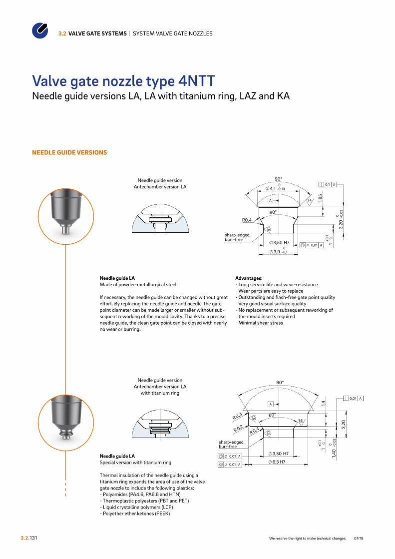
10+0
,1
3,20
-0,0
20
3,50 H7
-0,10
-0,100
60°
90°
R0,4
Detail X: Ausführung NadelführungVorkammer - Ausführung LA
0,4
0,4
0,01 A
0,1 A
A
Ausführung NadelführungVorkammer - Ausführung LA
sharp-edged, burr-free
3,9
4,1
1,85
10+0
,1
3,20
-0,0
20
3,50 H7
-0,10
-0,100
60°
90°
R0,4
Detail X: Ausführung NadelführungVorkammer - Ausführung LA
0,4
0,4
0,01 A
0,1 A
A
Ausführung NadelführungVorkammer - Ausführung LA
sharp-edged, burr-free
3,9
4,1
1,85
10+0
,1
H7
3,50 H7
R0,2
R0,4
R0,4 3,20
60°
60°
1,40
-0,0
20
Detail X: Ausführung NadelführungVorkammer - Ausführung LAmit Titanring
0,4
0,4
1,6
0,01 A
0,01 A
0,01 A
A
Ausführung NadelführungVorkammer - Ausführung LAmit Titanring
sharp-edged, burr-free
6,5
1,4
10+0
,1
H7
3,50 H7
R0,2
R0,4
R0,4 3,20
60°
60°
1,40
-0,0
20
Detail X: Ausführung NadelführungVorkammer - Ausführung LAmit Titanring
0,4
0,4
1,6
0,01 A
0,01 A
0,01 A
A
Ausführung NadelführungVorkammer - Ausführung LAmit Titanring
sharp-edged, burr-free
6,5
1,4
3.2 VALVE GATE SYSTEMS | SYSTEM VALVE GATE NOZZLES
3.2.131 We reserve the right to make technical changes. 07/18
NEEDLE GUIDE VERSIONS
Needle guide version Antechamber version LA
Needle guide version Antechamber version LA
with titanium ring
Valve gate nozzle type 4NTTNeedle guide versions LA, LA with titanium ring, LAZ and KA
Needle guide LAMade of powder-metallurgical steel
If necessary, the needle guide can be changed without great effort. By replacing the needle guide and needle, the gate point diameter can be made larger or smaller without sub-sequent reworking of the mould cavity. Thanks to a precise needle guide, the clean gate point can be closed with nearly no wear or burring.
Advantages:- Long service life and wear-resistance- Wear parts are easy to replace- Outstanding and flash-free gate point quality- Very good visual surface quality- No replacement or subsequent reworking of
the mould inserts required- Minimal shear stress
Needle guide LASpecial version with titanium ring
Thermal insulation of the needle guide using a titanium ring expands the area of use of the valve gate nozzle to include the following plastics:- Polyamides (PA4.6, PA6.6 and HTN)- Thermoplastic polyesters (PBT and PET)- Liquid crystalline polymers (LCP)- Polyether ether ketones (PEEK)

-0,10
90°
S7 H6
70°
-0,10
3,20
-0,0
20
t6±0
,05
0,58
0+ 0,0
5
R0,4
Detail X: Ausführung NadelführungVorkammer - Ausführung LAZ
0,4
0,4
0,01 A
0,01 A
A
Ausführung NadelführungVorkammer - Ausführung LAZ
sharp-edged, burr-free
4,1
3,9
R0,
5
45°
0,3
-0 0,1
D ++
0,0070,003
Detail Y: Ausführung NadelführungVorkammer - Ausführung KA
1,6
ground0,2
0,005 A
Ausführung NadelführungVorkammer - Ausführung KA
sharp-edged, burr-free
-0,10
90°
S7 H6
70°
-0,10
3,20
-0,0
20
t6±0
,05
0,58
0+ 0,0
5
R0,4
Detail X: Ausführung NadelführungVorkammer - Ausführung LAZ
0,4
0,4
0,01 A
0,01 A
A
Ausführung NadelführungVorkammer - Ausführung LAZ
sharp-edged, burr-free
4,1
3,9
R0,
5
45°
0,3
-0 0,1
D ++
0,0070,003
Detail Y: Ausführung NadelführungVorkammer - Ausführung KA
1,6
ground0,2
0,005 A
Ausführung NadelführungVorkammer - Ausführung KA
sharp-edged, burr-free
3.2.13107/18 We reserve the right to make technical changes.
Valve gate nozzle type 4NTT
Needle guide version Antechamber version LAZ
Needle guide version Antechamber version KA
Installation dimensions of needle guide version LAZ
ØD ØS7 t60.8 2.2 1.411.0 2.4 1.551.2 2.6 1.701.4 2.8 1.84
Needle guide LAZMade of powder-metallurgical steel
If necessary, the needle guide can be changed without great effort. By replacing the needle guide and needle, the gate point diameter can be made larger or smaller without subsequent reworking of the mould cavity. Thanks to a precise needle guide, the clean gate point can be closed with nearly no wear or burring. Needle guide type LAZ has a tapered shape with a smaller contact surface which creates a smaller impression. This version is suitable for items with a minimal wall thickness and part geometries not permitting a larger impression.
Advantages:- Long service life and wear-resistance- Wear parts are easy to replace- Outstanding and flash-free gate point quality- Very good visual surface quality- No replacement or subsequent reworking of
the mould inserts required- Minimal shear stress
Needle guide KAThis is used when a second marking on the part is not permissible.
When selecting the material to be used, the needle hardness of 64 ±2 HRC is to be taken into account!

TECHNICAL DATA
5NTT
Needle Ød 3 mm
Melt channel Ød 4.8 mm
Gate point Ød 0.8, 1.0, 1.2 or 1.4 mm
Operating voltage 230 VAC*
Nominal length of the nozzle (L) in mm
50 60 80 100 120
Contact us for other nozzle lengths!
*Volts alternating current
available
NOTE
Power connector CMT and thermocouple connector CMLK are to be ordered separately.
3.2 VALVE GATE SYSTEMS | SYSTEM VALVE GATE NOZZLES
3.2.140
Valve gate nozzle type 5NTTSystem nozzle with conventional heating element, screwed from the parting line
WEBCODE32120
We reserve the right to make technical changes. 08/20

0,5x
45°
50+0
,1
19 H7
R2 90°
18 H7
18,5 +
0,40
L + 0,
020
28
R8
45°
45°
6,9
-0 0,2
1,2
-0 0,
1
Geschlossene Düse mit Nadelführung- Vorkammer - Ausführung KA
1,6
1,6
6,3
6,3
0,02 A
0,02 A
A
90°
28
L0+0
,02
0,5 x
45
50+0
,10
19 H7
18,5 0+0,4
18 H7
R2
R2
45°
45°
10,6 0+0,1
6,9
-0,20
Geschlossene Düse mit Nadelführung- Vorkammer - Ausführung LA
1,6
1,6
6,3
6,3
0,02 A
0,02 A
A
„X“
38
L
+ 0,02
0
18
2
6
VH
4,8
("K
")
Clamping plate
Manifold
Cavity plate
Nozzle holding plate
1Shut-o� needle
27 H7
38 H7
14,
5 + 0,
050
1 x
45°
1
x 4
5°
0,02 A
0,02 A
A
M4
11,
5
9
R4,5
Ø33
1
22
R10
TK 34 ±0,05
SW
28
22,5°
M4
Thermocouple connector CMLK
Power connector CMT
15
3.2.140
Valve gate nozzle type 5NTT
Example cutout for nozzle head, power and thermocouple plug connections
INSTALLATION
Nozzle with needle guide antechamber design KA
Nozzle with needle guide antechamber design LA
1 Power and thermocouple plug connections in this area can be bent once; minimum radius: R8
SW = flat area on nozzle head
VH ∆T (°C) 100 150 200 250 300 350
36 mm K (mm) 0.021 0.059 0.098 0.137 0.177 0.217
46 mm K (mm) 0.033 0.078 0.124 0.170 0.218 0.264
56 mm K (mm) 0.046 0.097 0.150 0.203 0.258 0.311
Dimension “K” required for heat expansion is to be ensured by grinding the pressure pad (12 + 0.1 mm)! Determine the difference between the height of the manifold system and the height of the frame plate when installed! ∆T speci-fies the temperature differential between the processing temperature and the mould temperature!
For “X” version of the needle guide see following page
08/20 We reserve the right to make technical changes.

10+0
,1
3,20
-0,0
20
3,50 H7
4,6 -0,10
5 -0,100
60°
90°
1,25
R0,4
Detail X: Ausführung NadelführungVorkammer - Ausführung LA
0,4
0,4
0,01 A
0,1 A
A
Ausführung NadelführungVorkammer - Ausführung LA
sharp-edged, burr-free
10+0
,1
3,20
-0,0
20
3,50 H7
4,6 -0,10
5 -0,100
60°
90°
1,25
R0,4
Detail X: Ausführung NadelführungVorkammer - Ausführung LA
0,4
0,4
0,01 A
0,1 A
A
Ausführung NadelführungVorkammer - Ausführung LA
sharp-edged, burr-free
10+0
,1
7 H7
3,50 H7
R0,2
R0,4
R0,4 3,20
60°
60°
1,40
-0,0
20
1,50
Detail X: Ausführung NadelführungVorkammer - Ausführung LAmit Titanring
0,4
0,4
1,6
0,01 A
0,01 A
0,01 A
A
Ausführung NadelführungVorkammer - Ausführung LAmit Titanring
sharp-edged, burr-free
10+0
,1
7 H7
3,50 H7
R0,2
R0,4
R0,4 3,20
60°
60°
1,40
-0,0
20
1,50
Detail X: Ausführung NadelführungVorkammer - Ausführung LAmit Titanring
0,4
0,4
1,6
0,01 A
0,01 A
0,01 A
A
Ausführung NadelführungVorkammer - Ausführung LAmit Titanring
sharp-edged, burr-free
3.2 VALVE GATE SYSTEMS | SYSTEM VALVE GATE NOZZLES
3.2.141 We reserve the right to make technical changes. 07/18
NEEDLE GUIDE VERSIONS
Needle guide version Antechamber version LA
Needle guide version Antechamber version LA
with titanium ring
Valve gate nozzle type 5NTTNeedle guide versions LA, LA with titanium ring, LAZ and KA
Needle guide LAMade of powder-metallurgical steel
If necessary, the needle guide can be changed without great effort. By replacing the needle guide and needle, the gate point diameter can be made larger or smaller without sub-sequent reworking of the mould cavity. Thanks to a precise needle guide, the clean gate point can be closed with nearly no wear or burring.
Advantages:- Long service life and wear-resistance- Wear parts are easy to replace- Outstanding and flash-free gate point quality- Very good visual surface quality- No replacement or subsequent reworking of
the mould inserts required- Minimal shear stress
Needle guide LASpecial version with titanium ring
Thermal insulation of the needle guide using a titanium ring expands the area of use of the valve gate nozzle to include the following plastics:- Polyamides (PA4.6, PA6.6 and HTN)- Thermoplastic polyesters (PBT and PET)- Liquid crystalline polymers (LCP)- Polyether ether ketones (PEEK)

5 -0,10
90°
S7 H6
70°
4,6 -0,10
3,20
-0,0
20
t6±0
,05
0,58
0+ 0,0
5
R0,4
Detail X: Ausführung NadelführungVorkammer - Ausführung LAZ
0,4
0,4
0,01 A
0,01 A
A
Ausführung NadelführungVorkammer - Ausführung LAZ
sharp-edged, burr-free
R0,
5
45°
0,3
-0 0,1
D ++
0,0070,003
Detail Y: Ausführung NadelführungVorkammer - Ausführung KA
1,6
ground0,2
0,005 A
Ausführung NadelführungVorkammer - Ausführung KA
sharp-edged, burr-free
3.2.14101/18 We reserve the right to make technical changes.
Valve gate nozzle type 5NTT
Needle guide version Antechamber version LAZ
Needle guide version Antechamber version KA
Installation dimensions of needle guide version LAZ
ØD ØS7 t60.8 2.2 0.911.0 2.4 1.051.2 2.6 1.201.4 2.8 1.34
Needle guide LAZMade of powder-metallurgical steel
If necessary, the needle guide can be changed without great effort. By replacing the needle guide and needle, the gate point diameter can be made larger or smaller without subsequent reworking of the mould cavity. Thanks to a precise needle guide, the clean gate point can be closed with nearly no wear or burring. Needle guide type LAZ has a tapered shape with a smaller contact surface which creates a smaller impression. This version is suitable for items with a minimal wall thickness and part geometries not permitting a larger impression.
Advantages:- Long service life and wear-resistance- Wear parts are easy to replace- Outstanding and flash-free gate point quality- Very good visual surface quality- No replacement or subsequent reworking of
the mould inserts required- Minimal shear stress
Needle guide KAThis is used when a second marking on the part is not permissible.
When selecting the material to be used, the needle hardness of 64 ±2 HRC is to be taken into account!

TECHNICAL DATA
6NTT
Needle Ød 3 mm
Melt channel Ød 6 mm
Gate point Ød 0.8, 1.0, 1.2 or 1.4 mm
Operating voltage 230 VAC*
Nominal length of the nozzle (L) in mm
50 60 80 100 120
Contact us for other nozzle lengths!
*Volts alternating current
available
NOTE
Power connector CMT and thermocouple connector CMLK are to be ordered separately.
3.2 VALVE GATE SYSTEMS | SYSTEM VALVE GATE NOZZLES
3.2.150
Valve gate nozzle type 6NTTSystem nozzle with conventional heating element, screwed from the parting line
WEBCODE32130
We reserve the right to make technical changes. 08/20

0,5x
45°
50+0
,1
23 H7
R2 90°
22 H7
22,5 +
0,40
L + 0,
020
32
R8
45°
45°
8,9
-0 0,2
1,2
-0 0,
1
Geschlossene Düse mit Nadelführung- Vorkammer - Ausführung KA
1,6
1,6
6,3
6,3
0,02 A
0,02 A
A
90°
32
L0+0
,02
0,5x
45
50+0
,10
23 H7
22,5 0+0,4
22 H7
R2
R2
45°
45°
10,6 0+0,1
8,9
-0,20
Geschlossene Düse mit Nadelführung- Vorkammer - Ausführung LA
1,6
1,6
6,3
6,3
0,02 A
0,02 A
A
„X“
38
L
+0,0
20
18
2
6
VH
6
("K
")
Clamping plate
Manifold
Cavity plate
Nozzle holding plate
1Shut-o needle
27 H7
38 H7
14,
5 + 0,
050
1 x
45°
1
x 4
5°
0,02 A
0,02 A
A
M4
11,
5
9
R4,5
Ø33
1
22
R10
TK 34 ±0,05
SW
28
22,5°
M4
Thermocouple connector CMLK
Power connector CMT
15
3.2.150
Valve gate nozzle type 6NTT
Example cutout for nozzle head, power and thermocouple plug connections
INSTALLATION
Nozzle with needle guide antechamber design KA
Nozzle with needle guide antechamber design LA
1 Power and thermocouple plug connections in this area can be bent once; minimum radius: R8
SW = flat area on nozzle head
VH ∆T (°C) 100 150 200 250 300 350
36 mm K (mm) 0.021 0.059 0.098 0.137 0.177 0.217
46 mm K (mm) 0.033 0.078 0.124 0.170 0.218 0.264
56 mm K (mm) 0.046 0.097 0.150 0.203 0.258 0.311
Dimension “K” required for heat expansion is to be ensured by grinding the pressure pad (12 + 0.1 mm)! Determine the difference between the height of the manifold system and the height of the frame plate when installed! ∆T speci-fies the temperature differential between the processing temperature and the mould temperature!
For “X” version of the needle guide see following page
08/20 We reserve the right to make technical changes.

10+0
,1
3,20
-0,0
20
3,50 H7
4,6 -0,10
5 -0,100
60°
90°
1,25
R0,4
Detail X: Ausführung NadelführungVorkammer - Ausführung LA
0,4
0,4
0,01 A
0,1 A
A
Ausführung NadelführungVorkammer - Ausführung LA
sharp-edged, burr-free
10+0
,1
3,20
-0,0
20
3,50 H7
4,6 -0,10
5 -0,100
60°
90°
1,25
R0,4
Detail X: Ausführung NadelführungVorkammer - Ausführung LA
0,4
0,4
0,01 A
0,1 A
A
Ausführung NadelführungVorkammer - Ausführung LA
sharp-edged, burr-free
10+0
,1
7 H7
3,50 H7
R0,2
R0,4
R0,4 3,20
60°
60°
1,40
-0,0
20
1,50
Detail X: Ausführung NadelführungVorkammer - Ausführung LAmit Titanring
0,4
0,4
1,6
0,01 A
0,01 A
0,01 A
A
Ausführung NadelführungVorkammer - Ausführung LAmit Titanring
sharp-edged, burr-free
10+0
,1
7 H7
3,50 H7
R0,2
R0,4
R0,4 3,20
60°
60°
1,40
-0,0
20
1,50
Detail X: Ausführung NadelführungVorkammer - Ausführung LAmit Titanring
0,4
0,4
1,6
0,01 A
0,01 A
0,01 A
A
Ausführung NadelführungVorkammer - Ausführung LAmit Titanring
sharp-edged, burr-free
3.2 VALVE GATE SYSTEMS | SYSTEM VALVE GATE NOZZLES
3.2.151 We reserve the right to make technical changes. 07/18
NEEDLE GUIDE VERSIONS
Needle guide version Antechamber version LA
Needle guide version Antechamber version LA
with titanium ring
Valve gate nozzle type 6NTTNeedle guide versions LA, LA with titanium ring, LAZ and KA
Needle guide LAMade of powder-metallurgical steel
If necessary, the needle guide can be changed without great effort. By replacing the needle guide and needle, the gate point diameter can be made larger or smaller without sub-sequent reworking of the mould cavity. Thanks to a precise needle guide, the clean gate point can be closed with nearly no wear or burring.
Advantages:- Long service life and wear-resistance- Wear parts are easy to replace- Outstanding and flash-free gate point quality- Very good visual surface quality- No replacement or subsequent reworking of
the mould inserts required- Minimal shear stress
Needle guide LASpecial version with titanium ring
Thermal insulation of the needle guide using a titanium ring expands the area of use of the valve gate nozzle to include the following plastics:- Polyamides (PA4.6, PA6.6 and HTN)- Thermoplastic polyesters (PBT and PET)- Liquid crystalline polymers (LCP)- Polyether ether ketones (PEEK)

5 -0,10
90°
S7 H6
70°
4,6 -0,10
3,20
-0,0
20
t6±0
,05
0,58
0+ 0,0
5
R0,4
Detail X: Ausführung NadelführungVorkammer - Ausführung LAZ
0,4
0,4
0,01 A
0,01 A
A
Ausführung NadelführungVorkammer - Ausführung LAZ
sharp-edged, burr-free
R0,
5
45°
0,3
-0 0,1
D ++
0,0070,003
Detail Y: Ausführung NadelführungVorkammer - Ausführung KA
1,6
ground0,2
0,005 A
Ausführung NadelführungVorkammer - Ausführung KA
sharp-edged, burr-free
5 -0,10
90°
S7 H6
70°
4,6 -0,10
3,20
-0,0
20
t6±0
,05
0,58
0+ 0,0
5
R0,4
Detail X: Ausführung NadelführungVorkammer - Ausführung LAZ
0,4
0,4
0,01 A
0,01 A
A
Ausführung NadelführungVorkammer - Ausführung LAZ
sharp-edged, burr-free
R0,
5
45°
0,3
-0 0,1
D ++
0,0070,003
Detail Y: Ausführung NadelführungVorkammer - Ausführung KA
1,6
ground0,2
0,005 A
Ausführung NadelführungVorkammer - Ausführung KA
sharp-edged, burr-free
3.2.15101/18 We reserve the right to make technical changes.
Valve gate nozzle type 6NTT
Needle guide version Antechamber version LAZ
Needle guide version Antechamber version KA
Installation dimensions of needle guide version LAZ
ØD ØS7 t60.8 2.2 0.911.0 2.4 1.051.2 2.6 1.201.4 2.8 1.34
Needle guide LAZMade of powder-metallurgical steel
If necessary, the needle guide can be changed without great effort. By replacing the needle guide and needle, the gate point diameter can be made larger or smaller without subsequent reworking of the mould cavity. Thanks to a precise needle guide, the clean gate point can be closed with nearly no wear or burring. Needle guide type LAZ has a tapered shape with a smaller contact surface which creates a smaller impression. This version is suitable for items with a minimal wall thickness and part geometries not permitting a larger impression.
Advantages:- Long service life and wear-resistance- Wear parts are easy to replace- Outstanding and flash-free gate point quality- Very good visual surface quality- No replacement or subsequent reworking of t
he mould inserts required- Minimal shear stress
Needle guide KAThis is used when a second marking on the part is not permissible.
When selecting the material to be used, the needle hardness of 64 ±2 HRC is to be taken into account!