Embed Size (px)
Citation preview

Ultra Valve Gate Hot RunnerHot Runner Service Manual
Original Instructions

Issue: v 2.2 — March 2021
Document No.: 5275156
This product manual is intended to provide information for safe operation and/or maintenance.Husky reserves the right to make changes to products in an effort to continually improve theproduct features and/or performance. These changes may result in different and/or additionalsafety measures that are communicated to customers through bulletins as changes occur.
This document contains information which is the exclusive property of Husky Injection MoldingSystems Limited. Except for any rights expressly granted by contract, no further publication orcommercial use may be made of this document, in whole or in part, without the prior writtenpermission of Husky Injection Molding Systems Limited.
Notwithstanding the foregoing, Husky Injection Molding Systems Limited grants permission to itscustomers to reproduce this document for limited internal use only.
Husky® product or service names or logos referenced in these materials are trademarks of HuskyInjection Molding Systems Ltd. and may be used by certain of its affiliated companies underlicense.
All third-party trademarks are the property of the respective third-party and may be protected byapplicable copyright, trademark or other intellectual property laws and treaties. Each such third-party expressly reserves all rights into such intellectual property.
©2010 – 2021 Husky Injection Molding Systems Ltd. All rights reserved.
v 2.2 — March 2021 Ultra Valve Gate Hot Runner
ii

General Information
Telephone Support Numbers
North America Toll free 1-800-465-HUSKY (4875)
Europe EC (most countries) 008000 800 4300
Direct and Non-EC + (352) 52115-4300
Asia Toll Free 800-820-1667
Direct: +86-21-3849-4520
Latin America Brazil +55-11-4589-7200
Mexico +52-5550891160 option 5
For on-site service, contact your nearest Husky Regional Service and Sales office.
For non-emergency questions and issues you may also e-mail Husky at [email protected].
Husky Regional Service and Sales Offices
For the location closest to you, please visit www.husky.co.
Product Upgrades
Upgrades are available that can improve your output, reduce cycle times, and add functionality toyour Husky equipment.
To see what upgrades are available for your Husky equipment, visit our website at www.husky.coor call your nearest Husky Regional Service and Sales Office.
Ordering Spare Parts
All spare parts for Husky equipment can be ordered through your nearest Husky PartsDistribution Center or online at www.husky.co.
Hot Runner Service Manual v 2.2 — March 2021
Telephone Support Numbers iii

Hot Runner Refurbishing
Husky offers services for repairing, modifying, and retrofitting Husky hot runners. Contact yourHusky Regional Service and Sales office for details.
v 2.2 — March 2021 Ultra Valve Gate Hot Runner
iv Hot Runner Refurbishing

Table of ContentsGeneral Information..........................................................................................................................................iii
Telephone Support Numbers.................................................................................................................................................. iiiHusky Regional Service and Sales Offices........................................................................................................................... iiiProduct Upgrades........................................................................................................................................................................ iiiOrdering Spare Parts...................................................................................................................................................................iiiHot Runner Refurbishing.......................................................................................................................................................... iv
Chapter 1: Introduction................................................................................................................................... 111.1 Purpose of the Equipment............................................................................................................................................. 111.2 Restrictions of Use.............................................................................................................................................................111.3 Unauthorized Modifications..........................................................................................................................................111.4 Auxiliary Equipment.........................................................................................................................................................111.5 Documentation..................................................................................................................................................................12
1.5.1 Manuals................................................................................................................................................................ 121.5.2 Engineering Drawings and Schematics....................................................................................................131.5.3 Safety Alert Conventions............................................................................................................................... 13
1.6 Training................................................................................................................................................................................. 141.7 Nameplates..........................................................................................................................................................................14
1.7.1 Hot Runner Nameplate...................................................................................................................................141.8 Special Tools........................................................................................................................................................................16
1.8.1 Nozzle Tip Sockets and Heater Removal Tools.......................................................................................161.8.2 Valve Stem Removal Tools.............................................................................................................................171.8.3 Backup Pad Removal Tools............................................................................................................................171.8.4 Alignment Bushing Installation Tool......................................................................................................... 171.8.5 Front Ring Removal Tools.............................................................................................................................. 181.8.6 Double Delta Seal Installation Tools.......................................................................................................... 181.8.7 Retaining Clip Installation Tool....................................................................................................................181.8.8 Standard Nozzle Tip Sockets.........................................................................................................................181.8.9 Thermocouple Wire Stripping Tools.......................................................................................................... 191.8.10 Single Probe Thermocouple Removal Tools.........................................................................................201.8.11 Crimping Tools for Contact Pins (25 or 64 Pin Connectors)............................................................ 20
Chapter 2: Safety Summary.............................................................................................................................212.1 Qualified Personnel.......................................................................................................................................................... 212.2 Safety Guidelines...............................................................................................................................................................212.3 Safety Hazards.................................................................................................................................................................... 21
2.3.1 Mechanical Hazards.........................................................................................................................................222.3.2 Burn Hazards...................................................................................................................................................... 222.3.3 High Pressure Hazards.................................................................................................................................... 232.3.4 Electrical Hazards..............................................................................................................................................242.3.5 Gas, Vapor and Dust Emissions....................................................................................................................242.3.6 Slip, Trip or Fall Hazards..................................................................................................................................242.3.7 Lifting Hazards...................................................................................................................................................24
Hot Runner Service Manual v 2.2 — March 2021 Table of Contents
v

2.4 Safety Signs......................................................................................................................................................................... 242.5 Lockout and Tagout..........................................................................................................................................................262.6 Personal Protective Equipment and Safety Equipment...................................................................................... 27
2.6.1 Personal Protective Equipment (PPE)........................................................................................................272.6.2 Safety Equipment............................................................................................................................................. 28
2.7 Material Safety Data Sheet (MSDS)............................................................................................................................. 292.8 Materials, Parts and Processing.................................................................................................................................... 292.9 Safety Latch Bars................................................................................................................................................................292.10 Lift Bars and Swivel Hoist Rings................................................................................................................................. 30
Chapter 3: Specifications................................................................................................................................. 313.1 Weight................................................................................................................................................................................... 313.2 Operating Temperature.................................................................................................................................................. 313.3 Electrical System Specifications................................................................................................................................... 31
3.3.1 Controller Requirements................................................................................................................................313.3.2 Nozzle Heaters................................................................................................................................................... 323.3.3 Manifold Heaters...............................................................................................................................................32
3.3.3.1 Spare Thermocouple Wires.......................................................................................................... 323.3.4 Power Fluctuation............................................................................................................................................ 33
3.4 Pneumatic Specifications............................................................................................................................................... 333.5 Recommended Lubricants.............................................................................................................................................343.6 Rust Inhibitor Specifications..........................................................................................................................................353.7 Torque Specifications.......................................................................................................................................................36
Chapter 4: Installation and Removal.............................................................................................................. 374.1 Lifting and Handling........................................................................................................................................................ 37
4.1.1 Lifting and Handling Using a Single Lifting Point.................................................................................384.1.1.1 Laying Down Plates Using a Single Lifting Point.................................................................. 384.1.1.2 Picking Up Plates Using a Single Lifting Point.......................................................................39
4.1.2 Lifting and Handling Using Multiple Lifting Points..............................................................................404.1.3 Lifting Using a Lift Bar..................................................................................................................................... 414.1.4 Lifting Using Swivel Hoist Rings.................................................................................................................. 42
4.2 Mounting Methods...........................................................................................................................................................434.2.1 Direct Bolting..................................................................................................................................................... 434.2.2 Clamping............................................................................................................................................................. 444.2.3 Quick Mold Changers and Clamping Systems....................................................................................... 45
4.3 Removing and Installing the Hot Runner................................................................................................................. 454.3.1 Installing the Hot Runner...............................................................................................................................454.3.2 Removing the Hot Runner.............................................................................................................................47
Chapter 5: Startup and Operation.................................................................................................................. 515.1 Preparing the Hot Runner.............................................................................................................................................. 515.2 Heating Up the Hot Runner, Mold and Machine....................................................................................................525.3 Precharging the Hot Runner..........................................................................................................................................535.4 Producing Test Parts.........................................................................................................................................................54
Chapter 6: Maintenance...................................................................................................................................57
v 2.2 — March 2021 Ultra Valve Gate Hot Runner
vi

6.1 Scheduled and Non-Scheduled Maintenance........................................................................................................576.1.1 Preventive Maintenance.................................................................................................................................586.1.2 Service Procedures...........................................................................................................................................58
6.2 Changing the Resin Color...............................................................................................................................................596.3 Extending Nozzle and Sprue Heater Wire Leads....................................................................................................606.4 Measuring Preload............................................................................................................................................................ 61
6.4.1 Measuring Preload for Manifolds in VG-LX and EX Systems............................................................. 626.4.2 Measuring Preload for Manifolds in VG-SX Systems............................................................................ 626.4.3 Measuring Preload for Cross Manifolds in Two Plate Systems (If Equipped).............................. 646.4.4 Measuring Preload for Cross Manifolds in Three Plate Systems (If Equipped)........................... 65
6.5 Testing Heaters...................................................................................................................................................................676.6 Removing and Installing the Cavity Plate.................................................................................................................67
6.6.1 Removing the Cavity Plate On a Work Bench.........................................................................................686.6.2 Installing the Cavity Plate On a Work Bench...........................................................................................696.6.3 Removing the Cavity Plate In the Machine............................................................................................. 716.6.4 Installing the Cavity Plate In the Machine............................................................................................... 73
6.7 Removing and Installing the Backing Plate............................................................................................................. 746.7.1 Removing the Backing Plate.........................................................................................................................756.7.2 Installing the Backing Plate...........................................................................................................................77
6.8 Removing and Installing the Center Plate (If Equipped).....................................................................................796.8.1 Removing the Center Plate (If Equipped)................................................................................................ 796.8.2 Installing the Center Plate (If Equipped).................................................................................................. 81
6.9 Removing and Installing Manifolds............................................................................................................................836.9.1 Removing a Cross Manifold (If Equipped)............................................................................................... 836.9.2 Removing a Manifold...................................................................................................................................... 846.9.3 Inspecting and Cleaning Manifolds........................................................................................................... 866.9.4 Installing a Manifold........................................................................................................................................ 876.9.5 Installing a Cross Manifold (If Equipped)................................................................................................. 90
6.10 Removing and Installing VG-LX and EX Backup Pads........................................................................................916.10.1 Removing the VG-LX and EX Backup Pads............................................................................................916.10.2 Installing the VG-LX and EX Backup Pads..............................................................................................92
6.11 Removing and Installing VG-SX Cylinders............................................................................................................. 936.11.1 Removing Cylinders...................................................................................................................................... 936.11.2 Installing Cylinders........................................................................................................................................ 94
6.12 Removing and Installing Valve Stems..................................................................................................................... 956.12.1 Removing the Valve Stems for U350 and U500 VG-SX Systems....................................................966.12.2 Installing the Valve Stems for U350 and U500 VG-SX Systems................................................... 1006.12.3 Removing the Valve Stems for U500 and U750 VG-LX and EX Systems...................................1056.12.4 Installing the Valve Stems for U500 and U750 VG-LX and EX Systems.....................................1096.12.5 Removing the Valve Stems for U1000 VG-LX Systems................................................................... 1116.12.6 Installing the Valve Stems for U1000 VG-LX Systems..................................................................... 116
6.13 Replacing the Double Delta Seals.......................................................................................................................... 1186.14 Removing and Installing Nozzle Tips.................................................................................................................... 119
6.14.1 Removing the Nozzle Tips when Hot................................................................................................... 1206.14.2 Removing the Nozzle Tips when Cold................................................................................................. 1226.14.3 Removing U750 Nozzle Tips with U1000 VG-EXX RGA Nozzles..................................................1246.14.4 Installing the Nozzle Tips.......................................................................................................................... 1256.14.5 Installing U750 Nozzle Tips with U1000 VG-EXX RGA Nozzles....................................................1276.14.6 Troubleshooting Nozzle Tip Heights.................................................................................................... 128
Hot Runner Service Manual v 2.2 — March 2021 Table of Contents
vii

6.15 Refurbishing Ultra Flow VG Nozzle Tips............................................................................................................... 1296.16 Removing and Installing Nozzle Housings..........................................................................................................129
6.16.1 Removing VG-LX and EX and SX Nozzle Housings..........................................................................1306.16.2 Installing VG-LX and EX and SX Nozzle Housings............................................................................1306.16.3 Removing VG-HP and VX-HP Nozzle Housings.................................................................................1316.16.4 Installing VG-HP and VX-HP Nozzle Housings...................................................................................1326.16.5 Inspecting and Cleaning Nozzle Housings.........................................................................................133
6.17 Removing and Installing Nozzle Heaters.............................................................................................................1346.17.1 Removing and Installing HTM Nozzle Heaters for U350, U500 and U750 Systems............. 134
6.17.1.1 Removing HTM Nozzle Heaters for U350, U500 and U750 Systems.........................1346.17.1.2 Installing HTM Nozzle Heaters for U350, U500 and U750 Systems...........................135
6.17.2 Removing and Installing HTM Nozzle Heaters for U1000 Systems............................................1376.17.2.1 Removing HTM Nozzle Heaters for U1000 Systems....................................................... 1376.17.2.2 Installing HTM Nozzle Heaters for U1000 Systems......................................................... 137
6.17.3 Removing and Installing Copper Nozzle Heaters............................................................................ 1396.17.3.1 Removing Copper Nozzle Heaters........................................................................................ 1396.17.3.2 Installing Copper Nozzle Heaters.......................................................................................... 140
6.17.4 Removing and Installing Ultra Nozzle Heaters With Front Rings (UNH 500 and 750)........ 1416.17.4.1 Removing Ultra Nozzle Heaters (UNH) With Front Rings..............................................1416.17.4.2 Installing Ultra Nozzle Heaters (UNH) with Front Rings................................................ 142
6.17.5 Removing and Installing Ultra Nozzle Heaters (UNH) With Ring Thermocouples............... 1446.17.5.1 Removing Ultra Nozzle Heaters (UNH) With Ring Thermocouples...........................1446.17.5.2 Installing Ultra Nozzle Heaters (UNH) With Ring Thermocouples.............................145
6.17.6 Removing and Installing Bi-Metal Nozzle Heaters...........................................................................1506.17.6.1 Removing Bi-Metal Nozzle Heaters...................................................................................... 1506.17.6.2 Installing Bi-Metal Nozzle Heaters........................................................................................ 150
6.17.7 Removing and Installing VG-HP Nozzle Heaters.............................................................................. 1516.17.7.1 Removing VG-HP Nozzle Heaters..........................................................................................1526.17.7.2 Installing VG-HP Nozzle Heaters............................................................................................152
6.18 Removing and Installing Nozzle Tip Insulators (If Equipped).......................................................................1546.18.1 Removing the Nozzle Tip Insulators..................................................................................................... 1546.18.2 Installing the Nozzle Tip Insulators....................................................................................................... 155
6.19 Removing Insulating Gate Bubbles (If Equipped)............................................................................................ 1566.20 Removing and Installing Manifold Bushings......................................................................................................160
6.20.1 Removing and Installing Press Fit Manifold Bushings....................................................................1606.20.2 Removing Slip Fit Manifold Bushings...................................................................................................1606.20.3 Installing Slip Fit Manifold Bushings.....................................................................................................161
6.21 Removing and Installing the Sprue Heater (If Equipped)..............................................................................1626.21.1 Removing a Sprue Heater with a Built-In Thermocouple............................................................. 1626.21.2 Removing a Sprue Heater with a Separate Thermocouple.......................................................... 1636.21.3 Installing a Sprue Heater with a Built-In Thermocouple................................................................1636.21.4 Installing a Sprue Heater with a Separate Thermocouple............................................................ 164
6.22 Removing and Installing the Sprue Bushing......................................................................................................1666.22.1 Removing the Sprue Bushing..................................................................................................................1666.22.2 Installing the Sprue Bushing....................................................................................................................166
6.23 Removing and Installing Transfer Bushings (If Equipped).............................................................................1686.23.1 Removing Transfer Bushings (If Equipped)........................................................................................ 1686.23.2 Installing Transfer Bushings (If Equipped).......................................................................................... 169
6.24 Adjusting the Thermocouple Wire Length..........................................................................................................171
v 2.2 — March 2021 Ultra Valve Gate Hot Runner
viii

6.25 Removing Air and Water Plugs................................................................................................................................1726.26 Removing Resin from the Hot Runner .................................................................................................................174
6.26.1 Plate Cleaning and Inspection................................................................................................................ 1746.26.2 Cleaning Using a Fluidized Bed Process.............................................................................................. 176
6.26.2.1 Assistance...................................................................................................................................... 1766.26.2.2 Disassembling the Hot Runner for Fluidized Bed Cleaning.........................................1766.26.2.3 Removing the PEEK Bushings.................................................................................................178
6.27 Removing Resin from the Manifold Plate............................................................................................................ 179
Chapter 7: Storage and Shipping..................................................................................................................1817.1 Corrosion Protection......................................................................................................................................................1817.2 Short Term Storage........................................................................................................................................................ 181
7.2.1 Storing in the Machine.................................................................................................................................1827.2.2 Storing Outside the Machine.....................................................................................................................182
7.3 Long Term Storage......................................................................................................................................................... 1837.4 Shipping the Hot Runner............................................................................................................................................. 183
Hot Runner Service Manual v 2.2 — March 2021 Table of Contents
ix

v 2.2 — March 2021 Ultra Valve Gate Hot Runner
x

Chapter 1 Introduction
This chapter describes the hot runner, training opportunities, and the available equipmentmanuals.
1.1 Purpose of the Equipment
Husky equipment and systems are designed for injection molding applications only, usingapproved materials and operating within design guidelines.
Contact your nearest Husky Regional Service and Sales office if you plan to use a Husky productfor anything other than its intended use.
1.2 Restrictions of Use
Husky injection molding equipment must never be:
• operated by more than one person• used for any purpose other than that described in Section 1.1, unless otherwise approved by
Husky• used to extrude any materials not outlined in the scope of the harmonized EN201 or ANSI
B151.1 standard• operated or serviced by personnel unfamiliar with the inherent risks and necessary
precautions related to injection molding equipment• operated at temperatures higher than the maximum permissible temperature for the resin
1.3 Unauthorized Modifications
Unauthorized modifications or reconstruction of any Husky injection molding system is strictlyprohibited. Modifications can be unsafe and/or void warranty.
Contact your nearest Husky Regional Service and Sales office to discuss modifications orrequirements for Husky systems.
1.4 Auxiliary Equipment
Husky is only responsible for the interaction of Husky equipment and systems with auxiliaryequipment when Husky is the system integrator. If auxiliary equipment is removed, the user mustinstall proper safeguards to prevent access to the hazards.
Hot Runner Service Manual v 2.2 — March 2021 Introduction
Purpose of the Equipment 11

For information about integrating non-Husky auxiliary equipment, contact your nearest HuskyRegional Service and Sales office.
1.5 Documentation
A full set of manuals, drawings, schematics, certificates and other documentation are available forevery Husky hot runner.
The following describes the documentation provided with each system, along with commonconventions all readers should be familiar with.
IMPORTANT!
Keep all manuals in a convenient location for future reference.
1.5.1 Manuals
Husky manuals aid in the safe and proper use of Husky products. Where applicable, the manualsprovide instructions on installation, operation and maintenance.
Personnel should thoroughly review all manuals provided with their Husky equipment prior toperforming any tasks. Proceed with tasks only if all instructions are understood and always followapplicable workplace safety requirements.
IMPORTANT!
Images in the manuals are for reference only and may not represent specific equipment details.Refer to engineering drawings and schematics for specific details.
The following manuals are available for each hot runner system:
OperatorManual
Describes the basic startup, operation, shut down and daily maintenance of the hotrunner
Service Manual Describes the installation, startup, operation, shut down and maintenance the hotrunner
NOTE:Refer to the hot runner Service Manual for product specific instructions.
These manuals are available online through www.husky.co.
v 2.2 — March 2021 Ultra Valve Gate Hot Runner
12 Documentation

IMPORTANT!
Some manuals may contain addendums that detail new or updated information. Before reading amanual, make sure to review all available addendums located at the end of the manual.
1.5.2 Engineering Drawings and Schematics
Each Husky hot runner is provided with a set of drawings and schematics specific to the hotrunner. These are used for troubleshooting the hot runner and ordering spare parts.
NOTE:
Each drawing and schematic is specific to the hot runner it is provided with.
1.5.3 Safety Alert Conventions
Safety alerts highlight hazardous conditions that may arise during installation, operation ormaintenance and describe methods for avoiding personal injury and/or property damage.
Depending on the severity of the hazard, safety alerts start with one of the following signal words:Danger, Warning or Caution.
DANGER!
The DANGER safety alert indicates an imminently hazardous situation that, if not avoided,will result in death or serious injury.
WARNING!
The WARNING safety alert indicates a potentially hazardous situation that, if not avoided,could result in death or serious injury.
CAUTION!
The CAUTION safety alert indicates a potentially hazardous situation that, if not avoided,could result in property damage.
Other non-safety related alert types used in the manuals highlight important information neededby the user to install, operate or maintain the equipment properly. They may also, in some cases,describe best practices, offer an expanded explanation, or reference a related section in themanual.
Non-safety related alerts start with one of the following signal words: Note or Important.
Hot Runner Service Manual v 2.2 — March 2021 Introduction
Documentation 13

NOTE:
The NOTE alert is used to add information to a subject that does not fit within the general flow ofthe document.
IMPORTANT!
The IMPORTANT alert is used to highlight important steps, conditions, or considerations related tothe subject.
1.6 Training
All designated operators and maintenance personnel must be fully trained before using orservicing Husky injection molding systems.
If training is required, visit www.husky.co or contact your nearest Husky Regional Service andSales office to learn more about Husky’s training solutions.
IMPORTANT!
It is the obligation of the employer to properly train and instruct all personnel in the safe methodsof operation and maintenance. Manuals and other reference material, which have been preparedby Husky for the operation and maintenance of Husky equipment, do not in any way absolve theemployer from fulfilling these obligations and Husky disclaims liability for injury to personnelwhich is attributable to the employer's failure to do so.
1.7 Nameplates
Nameplates are affixed to the operator’s side of the mold and hot runner for quick identificationof the equipment type, source and general specifications.
IMPORTANT!
The mold and hot runner nameplates must never be removed. The information on thenameplates is necessary for mold selection, setup, parts ordering and troubleshooting.
Immediately order a new nameplate for the mold or hot runner if it is missing or damaged.
1.7.1 Hot Runner Nameplate
Every hot runner nameplate lists the following information:
v 2.2 — March 2021 Ultra Valve Gate Hot Runner
14 Training

• the location where the hot runner was manufactured• the project number• the material type allowed to be used in the hot runner• the melt and mold temperatures• electrical requirements and specifications
NOTE:
Other details and specifications may be required.
IMPORTANT!
Each hot runner is designed to process a specific type and grade of resin/filler based on thecustomer’s requirements. Use of any other type or grade of resin/filler could affect part qualityand/or the performance of the hot runner. Before using a different type or grade of resin/filler,contact Husky.
CAUTION!
Mechanical hazard – risk of damage to the hot runner. Never operate the hot runneroutside of the melt and mold temperatures indicated on the nameplate. Internal resinleakage or component damage could occur.
1
2
3
4
5
Figure 1-1: Hot Runner Nameplate (Sample)
1. Project Number 2. Resin Type Allowed 3. Melt and Mold Temperatures 4. Power Requirements 5. Temperature Warning
Hot Runner Service Manual v 2.2 — March 2021 Introduction
Nameplates 15

1.8 Special Tools
The following sections list various component-specific tools developed by Husky for use duringmaintenance of hot runner systems. Contact Husky to order special tools applicable to your hotrunner system.
1.8.1 Nozzle Tip Sockets and Heater Removal Tools
Nozzle Tip Part Number
Nozzle TipSocket
Heater Removal Tool
U350 All
38726868 mm (0.25
in)12 points
3163811 (Hex Key)OR
7287617 (Torque WrenchAssembly), 0.45 N·m (4 lbf·ft)
OR4715152 (Hex Driver)
3734732Large Pitch >28 mm (1.1 in)
OR6599345
Small Pitch ≤28 mm (1.1 in)
U500
VG
233805912 mm
(0.47 in) 6points
2341532 (Bi-Metal and UNH with Front Ring)3163811 (HTM Heater) Hex Key
4715152 (HTM Heater) Hex Driver7307376 (UNH with Ring Thermocouple)
7287617 (HTM Heater) Torque Wrench Assembly, 0.45 N·m (4lbf·ft)
53198311 mm
(0.43 in) 12points
VG-X 3436695
VG-XX
VX 3253169
U750
VG-R 531983 3163811 (HTM Heater) Hex Key4715152 (HTM Heater) Hex Driver
535160 (Bi-Metal and UNH with Front Ring)7298786 (UNH with Ring Thermocouple)
7287617 (HTM Heater) Torque Wrench Assembly, 0.45 N·m (4lbf·ft)
VG 2338059
VX 3253170
VG-EXXRGA
22 mm(0.87 in)
socket toremove
nozzle tipadapter
v 2.2 — March 2021 Ultra Valve Gate Hot Runner
16 Special Tools

Nozzle Tip Part Number
Nozzle TipSocket
Heater Removal Tool
U750-UP
UltraPackaging
(UP)
37229203756216
U1000VG 2449784
2410903 (Bi-Metal)VX 2816672
1.8.2 Valve Stem Removal Tools
Description Part Number
VG-LX 4793599
VG-EX 4793600
VG-SX 4793598
1.8.3 Backup Pad Removal Tools
Description Part Number
U350
2603927U500
U750
U1000 2948588
1.8.4 Alignment Bushing Installation Tool
Description Part Number
For 25mm ID Plate Alignment Bushings 7568206
Hot Runner Service Manual v 2.2 — March 2021 Introduction
Special Tools 17

1.8.5 Front Ring Removal Tools
Description Part Number
U500 3634736
U750 4925394
1.8.6 Double Delta Seal Installation Tools
Description Part Number
U350 VG-SX 3446999
U500 VG-SX
U350 VG-LX 3087823
U500 VG-LX
U750 VG-LX
U500 VG-EX 3446982
U750 VG-EX
U1000 VG-LX 3500798
1.8.7 Retaining Clip Installation Tool
Description Part Number
U350 4405801
1.8.8 Standard Nozzle Tip Sockets
Size Points Drive Part Number
4 mm 6 (Allen Key) 3/8 inch 622974
6 mm 6 (Allen Key) 3/8 inch 622972
6mm 6 3/8 inch 533942
8 mm 6 1/4 inch 2996145
v 2.2 — March 2021 Ultra Valve Gate Hot Runner
18 Front Ring Removal Tools

Size Points Drive Part Number
8 mm 12 1/4 inch 3436695
8 mm 6 3/8 inch 1501813
10 mm 12 3/8 inch 3253169
11 mm 6 3/8 inch 3320712
11 mm 12 3/8 inch 531983
12 mm 6 3/8 inch 2338059
13 mm 6 3/8 inch 536678
14 mm 12 3/8 inch 533533
15 mm 6 3/8 inch 2449784
15 mm 12 3/8 inch 3253170
16 mm 6 3/8 inch 2402461
16 mm 12 3/8 inch 2816670
17 mm 6 3/8 inch 2308879
20 mm 6 1/2 inch 3722920
21 mm 12 1/2 inch 3274535
22 mm 6 1/2 inch 3311845
22 mm 12 1/2 inch 2816672
29 mm 6 1/2 inch 1502743
30 mm 6 1/2 inch 535571
1/2 inch 6 3/8 inch 2192309
1.8.9 Thermocouple Wire Stripping Tools
Description Part Number
Strippers for Thermocouple Wires 4240042
Hot Runner Service Manual v 2.2 — March 2021 Introduction
Special Tools 19

1.8.10 Single Probe Thermocouple Removal Tools
Description Part Number
11 mm Split Socket 4395427
1.8.11 Crimping Tools for Contact Pins (25 or 64 Pin Connectors)
Description Part Number
Crimp Tool 2292562
Locator 2292574
Removal Tool 534645
Crimp Dies 0.5 to 1.5 mm2 (20 to 16 AWG)[1] 238569
4.0 to 10 mm2 (12 to 8 AWG)[1] 2292575
0.14 to 4.0 mm2 (26 to 12 AWG)[2] 2292576
0.14 to 0.5 mm2 (26 to 20 AWG)[1] 2748316
1.5 to 2.5 mm2 (16 to 14 AWG)[1] 2748326
[1] Stamped crimp pins.[2] Machined crimp pins.
v 2.2 — March 2021 Ultra Valve Gate Hot Runner
20 Single Probe Thermocouple Removal Tools

Chapter 2 Safety Summary
This chapter describes the general requirements and conditions for safe installation, operationand maintenance of the mold and hot runner.
IMPORTANT!
Personnel must read, understand and follow all safety precautions.
IMPORTANT!
Personnel must follow applicable industry and regulatory safety requirements for safeinstallation, operation and maintenance of equipment.
2.1 Qualified Personnel
Only fully trained and qualified personnel should be permitted to maintain equipment. Qualifiedpersonnel must have demonstrated skills and knowledge related to the construction, installationand operation of the injection molding equipment and have received safety training on thehazards involved.
2.2 Safety Guidelines
Personnel operating, installing, maintaining or servicing Husky equipment must adhere to safeworking practices that are in compliance with the following guidelines:
• Lockout and tag electrical, pneumatic and hydraulic energy sources before servicing themold/hot runner or entering the mold area
• Do not operate the mold/hot runner if scheduled preventive maintenance has not beenperformed
• Do not use a magnetic platen without approval from Husky and the magnetic platensupplier/manufacturer
• Do not operate a hot runner outside the maximum melt and mold temperatures specified onthe hot runner nameplate
2.3 Safety Hazards
Some common safety hazards associated with injection molding equipment are:
Hot Runner Service Manual v 2.2 — March 2021 Safety Summary
Qualified Personnel 21

• Mechanical• Electrical• Burn• High pressure (hydraulic system pressure and molten material spray)• Slip, trip or fall• Lifting• Gas, vapor and dust emissions• Noise
2.3.1 Mechanical Hazards
• Worn Hoses and Safety RestraintsRegularly inspect and replace all flexible hose assemblies and restraints.
• Cooling Water HosesCooling water hoses degrade over time and need to be replaced on a yearly basis. Degraded hosesbecome brittle and can break or separate from the fitting when manipulated. To minimize the riskof failure, inspect the hoses regularly and replace as required.Wait until the machine has cooled down before servicing cooling water hoses.
• Seized Screws or PlugsIf screws or plugs cannot be removed by normal methods using standard tooling and force, there isa high possibility these items have become seized; contact Husky for repair recommendation.
WARNING!
Mechanical and/or flying debris hazard - Tool breakage: risk projectile debris, serious injuryand/or mechanical damage. Do not use excessive force and/or use tools beyond theirdesignated limits. Do not use torque multiplying bars. Failure of tools may producefragments that can become projectiles that may cause injury. For seized parts, consultHusky for safe disassembly instructions.
NOTE:
Manifold plugs are not a field repairable item and should never be removed. These items can onlybe serviced at a Husky manufacturing location.
2.3.2 Burn Hazards
• Hot SurfacesThe mold area, auxiliary mold equipment, and injection unit heating elements have numerous hightemperature surfaces. At normal operating temperatures, contact with these surfaces will causesevere skin burns. These areas are clearly marked with safety signs. Wear personal protectiveequipment when working in these areas.
v 2.2 — March 2021 Ultra Valve Gate Hot Runner
22 Mechanical Hazards

• Molten MaterialNever touch process material purged or otherwise flowing from the nozzle, mold, hot runner orfeed throat area. Molten material can appear cool on the surface, but remain very hot on the inside.Wear personal protective equipment when handling purged material.
2.3.3 High Pressure Hazards
WARNING!
Burn and hot resin spray hazard – risk of death, serious injury and/or damage to the hotrunner. All nozzle and sprue heaters (if equipped) must be turned on when manifoldheaters are turned on. Failure to do so could result in generation of dangerous pressurelevels in the manifold, resulting in component failure and/or sudden release of hot resin.
Pressure inside the hot runner manifold(s) can increase to dangerous levels if the nozzle andsprue heaters (if equipped) are not turned on before or at the same time as the nozzle sprue.
The pressure is generated when the injection nozzle sprue is plugged with frozen resin and theresidual resin in the manifold is heated. This pressure can release suddenly causing the resin plugto eject from the sprue and hot resin to spray from the nozzle tips. The risk of serious burn injuriesas a result is increased.
Moisture that infiltrates and is trapped in the hot runner molten material can also increase therisks of this potential hazard. If the temperature of the water in the molten material becomesgreater than 400 °C (725 °F) , the pressure of this trapped water can be significant enough torupture the metal housing and cause serious injury to personnel.
To avoid this hazard, do the following:
1. Always make sure all nozzle and sprue heaters (if equipped) are turned on any time manifoldheaters are turned on outside of the mold. The nozzle and sprue heaters can be turned onindependently of the manifold heaters, however, it is recommended that they be heated firstor slaved to the manifold heaters so they heat up in unison.
2. Always make sure the nozzle tips are open and the nozzle housings are dry prior to applyingheat to the manifold.
IMPORTANT!
In the event of water leaking onto or into the hot runner, the nozzle tips must be removed (cold)and the plastic in the nozzles drilled out to ensure they are open to atmosphere. This can be doneusing a standard twist drill with the cutting edges removed to prevent damage to the meltchannel.
Replace the cavity plate prior to heating the system.
Hot Runner Service Manual v 2.2 — March 2021 Safety Summary
Safety Hazards 23

2.3.4 Electrical Hazards
• Power SupplyMolding equipment draws high amperage current at high voltage. The electrical powerrequirements are indicated on the nameplate and in the electrical schematics. Connect equipmentto a suitable power supply as specified in the electrical schematics and in compliance with allapplicable local regulations.
• WaterWater on the hot runner can be in close proximity to electrical connections and equipment. Thiscan lead to a short circuit, resulting in serious electrical damage to the equipment. Always keepwater lines, hoses, and hose fittings in good condition to avoid leaks.
2.3.5 Gas, Vapor and Dust Emissions
Certain processed materials release harmful gas, vapors or dust. Install an exhaust systemaccording to local codes.
2.3.6 Slip, Trip or Fall Hazards
Do not walk, stand, climb or sit on machine surfaces not approved for safe access.
Do not step on the tie bar or any surfaces with grease and/or oil.
Use a safety approved platform, walkway and step ladders designated to access areas that are notaccessible from the floor.
2.3.7 Lifting Hazards
When lifting equipment, use suitable lifting devices, proper balancing techniques and designatedlifting points. Refer to the installation details, and to handling and lifting instructions. Do notexceed the rated capacity of the lifting equipment.
2.4 Safety Signs
Safety signs clearly mark potentially hazardous areas in or around equipment. For the safety ofpersonnel involved in equipment installation, operation and maintenance, use the followingguidelines:
• Verify that all signs are in the proper locations. Refer to the drawing package for details.• Do not alter signs.• Keep signs clean and visible.• Order replacement signs when necessary. Refer to the drawing package for part numbers.
The following safety symbols may appear on safety signs:
v 2.2 — March 2021 Ultra Valve Gate Hot Runner
24 Electrical Hazards

NOTE:
Safety signs may include a detailed explanation of the potential hazard and associatedconsequences.
Safety Symbol(ANSI)
Safety Symbol(ISO)
General Description of Symbol
GeneralThis symbol indicates a potential personal injury hazard. It is
usually accompanied by another pictogram or text todescribe the hazard.
Hazardous VoltageThis symbol indicates a potential electrical hazard that will
cause death or serious injury.
High Pressure Molten MaterialThis symbol indicates the presence of a high pressure
molten material hazard that could cause death or severeburns.
Lockout/TagoutThis symbol identifies an energy source (electrical, hydraulic
or pneumatic) that must be de-energized beforemaintenance is performed.
Crushing and/or Impact PointsThis symbol indicates a crushing and/or impact area that
could cause serious crushing injury.
High PressureThis symbol indicates a heated water, steam or gas hazard
that could cause severe injury.
High Pressure AccumulatorThis symbol indicates the sudden release of high pressure
gas or oil could cause death or serious injury.
Hot SurfacesThis symbol identifies the presence of exposed hot surfaces
that could cause serious burn injuries.
Hot Runner Service Manual v 2.2 — March 2021 Safety Summary
Safety Signs 25

Safety Symbol(ANSI)
Safety Symbol(ISO)
General Description of Symbol
Slip, Trip or Fall HazardThis symbol indicates a slip, trip or fall hazard that could
cause injury.
Do Not StepThis symbol identifies a location that should not be used as a
step because it may be a slip, trip or fall hazard and couldcause injury.
Crushing and/or Shearing HazardThis symbol indicates the presence of a crushing and/orshearing hazard at the rotating screw that could cause
serious injury.
Read Manual Before OperationThis symbol indicates that qualified personnel should readand understand all instructions in the equipment manuals
before working on the equipment.
Class 2 Laser BeamThis symbol indicates a laser beam hazard that could cause
personal injury with prolonged exposure.
Barrel Cover Grounding StrapThis symbol indicates an electrical hazard related to thebarrel cover grounding strap that could cause death or
serious injury.
Do Not GreaseThis symbol indicates greasing is not required under normal
operating conditions. Greasing could cause equipmentfailure.
2.5 Lockout and Tagout
A lockout/tagout procedure in accordance with local codes must be performed on the machine,controller and auxiliary equipment before any maintenance activities are performed while in themachine or connected to an external energy source.
v 2.2 — March 2021 Ultra Valve Gate Hot Runner
26 Lockout and Tagout

WARNING!
Complete the Lockout/Tag out of all energy sources in accordance with applicable localcodes before performing maintenance activities. Failure to do so could result in seriousinjury or death. Refer to the machine and associated equipment manufacturer’s manual forinstructions.
Only qualified personnel should be permitted to install and remove locks and tags.
Lockout and tagout includes: the isolation of energy; depletion of stored energy; and preventionof re-energization from all energy sources.
2.6 Personal Protective Equipment and Safety Equipment
Personal injury can be avoided when personnel wear appropriate protective gear and use specialsafety equipment. The following describes the safety gear and equipment that should be usedwhen working with the machine and any auxiliary equipment.
2.6.1 Personal Protective Equipment (PPE)
Wear appropriate personal protective equipment when working on or near equipment. Standardpersonal protective equipment includes:
Item Description
Safety GlassesFor protecting the eyes from flying objects/particles, heat, sparks, splash from moltenmaterial, and more.
Face ShieldFor protecting the entire face area from flying objects/particles, heat, sparks, splashfrom molten material, and more.
Heat Resistant GlovesFor protecting the hands from extreme heats.
Hearing ProtectionFor protecting the ears from loud ambient noise.
Hot Runner Service Manual v 2.2 — March 2021 Safety Summary
Lockout and Tagout 27

Item Description
Safety ShoesFor protecting the feet from electrical shocks, crushing hazards, puncture hazards,splash from molten material, and more.
Non-Melting Natural Fiber Pants and Long Sleeved ShirtFor protecting the body from abrasions, cuts, and potential splash from moltenmaterial.
2.6.2 Safety Equipment
Use appropriate safety equipment when working on or near equipment.
Standard safety equipment includes:
• Exhaust FanFor collecting potentially harmful plastic fumes
• Purging ContainerFor containing hot resin purged from the injection unit
• Vacuum CleanerFor collecting spilled resin pellets and other debris that may create a falling hazard
• Stairs and LaddersFor ensuring safe access to areas of the machine
• Danger SignsFor warning other personnel to stand clear of a component or area of the machine
• Locks and TagsFor preventing the use of specific systems and components
• Fire ExtinguishersFor the expedient suppression of small fires
• Telescopic MirrorFor safely inspecting hot runner nozzle tips from outside the mold area
• Brass Hammers and Brass RodsFor safely removing dried resin deposits
v 2.2 — March 2021 Ultra Valve Gate Hot Runner
28 Safety Equipment

2.7 Material Safety Data Sheet (MSDS)
WARNING!
Chemical hazard - Some of the chemicals used with Husky equipment are potentiallyhazardous and could cause injury and illness. Before storing, handling, or working with anychemical or hazardous material, thoroughly read and understand each applicable MaterialSafety Data Sheet (MSDS), use recommended personal protective equipment and followthe manufacturer’s instructions.
The Material Safety Data Sheet (MSDS) is a technical document which indicates the potentialhealth effects of a hazardous product. It contains safety guidelines to protect personnel, as well asinformation about use, storage, handling, and emergency procedures.
Always refer to the applicable Material Safety Data Sheet before doing the following:
• handling a chemical product• disassembling any portion of Husky equipment that may result in exposure to a chemical
product
Contact the material supplier to obtain a copy of the MSDS sheet.
2.8 Materials, Parts and Processing
To prevent personal injury or damage to the equipment, make sure of the following:
• The equipment is only used for its intended purpose, as described in the manuals• The operating temperatures do not exceed the specified permissible maximum value for the
resin• The maximum temperature set point is set below the flash point of the material being
processed• Lubricants, oils, process materials and tools used on equipment meet Husky specifications• Only authentic Husky parts are used
2.9 Safety Latch Bars
All mold and hot runner assemblies are delivered with safety latch bars installed on the operatorand non-operator side of the assembly.
Safety latch bars are used to hold plates together for maintenance and installation purposes. Theyprovide a safe means for transporting and handling the assembly, and for securing plates that arenormally fastened together during normal operation.
Hot Runner Service Manual v 2.2 — March 2021 Safety Summary
Material Safety Data Sheet (MSDS) 29

WARNING!
Crushing hazard – risk of death or serious injury. Plates could separate from each other andfall during handling if not properly secured. Under no circumstances are multiple plates tobe handled with only one safety latch bar installed.
Safety latch bars must always be installed in pairs on diagonally opposite sides of the mold andhot runner assembly to provide equal pull on the plates.
NOTE:
Specific instructions on how to install safety latch bars are provided when needed in this manual.
2.10 Lift Bars and Swivel Hoist Rings
Every mold and hot runner assembly is equipped with tapped lift holes for lifting either thecomplete assembly or individual plates. Husky only supplies special lifting equipment (including alift bar and swivel hoist rings) when required. This lifting equipment is designed specifically forthe mold/hot runner assembly. When Husky provides special lifting equipment, use only Huskyspecified and supplied lifting equipment.
NOTE:
Separate lift bars for the hot and cold halves of the mold and hot runner assembly may beprovided based on the requirements of the assembly.
IMPORTANT!
Make sure all lifting equipment is rated for the load and in safe operating condition. Follow therecommendations and use care when moving or handling plates or assemblies.
For instructions about lifting plates and plate assemblies and using the Husky provided lift barand swivel hoist rings, refer to Section 4.1.
NOTE:
The Husky provided lift bar, swivel hoist rings and associated hardware must be stored togetherwhile the mold, hot runner, tooling plate and CoolPik plate are in operation.
v 2.2 — March 2021 Ultra Valve Gate Hot Runner
30 Lift Bars and Swivel Hoist Rings

Chapter 3 Specifications
This chapter outlines the necessary temperature, electrical, air and lubricant information neededto operate and maintain the hot runner.
3.1 Weight
The full weight of the hot runner assembly is listed on the assembly drawings.
3.2 Operating Temperature
The hot runner must operate within a specific temperature range to prevent internal resinleakage and damage to internal components as the result of thermal expansion. This temperaturerange is listed on the hot runner nameplate as the temperature difference between the manifoldand the mold.
IMPORTANT!
The temperature range is critical for the hot runner system to be able to create a proper seal. It isimportant the designed operating temperature window be observed at all times.
For more information about the nameplate, refer to Section 1.7.1.
3.3 Electrical System Specifications
Refer to the electrical schematic for the following information:
• Control zones• Multi-pin connector and pin positions for each heater and thermocouple wire• Connecting heater wiring in parallel (if applicable)• Amperage, wattage and resistance of each heater• Keypin locations
3.3.1 Controller Requirements
The number of control zones required for the heaters will depend on the size and requirements ofthe basic system.
Hot Runner Service Manual v 2.2 — March 2021 Specifications
Weight 31

DANGER!
Electrical hazard – risk of serious injury, fire and/or overload of electrical components. Donot use a controller with an amperage rating less than that required by the heaters. Do notuse a controller with a higher amperage rating than the connectors or cables to the hotrunner.
The type of controller can be either:
• Automatic control using a thermocouple to sense the nozzle tip temperature• Manual control where the controller is set to provide power during a percentage of time
There may be an optional switchbox for turning ON or OFF the power to individual nozzleheaters.
NOTE:
The controller output to the heaters must be set to 220 to 240 V, 50 to 60 Hz single phase.
3.3.2 Nozzle Heaters
The nozzle heaters can be controlled separately or in zones by manual controllers. Refer to theelectrical schematic for the correct configuration.
3.3.3 Manifold Heaters
Whenever possible, the manifold heaters are wired in parallel and controlled by a single controllerzone. The circuit will be completed either at the cable connector or at the manifold.
The heaters are connected in multiple zones if the total amperage of all the heaters connected inparallel exceeds the capacity of a single controller zone.
Each zone is connected to a separate controller zone with its own thermocouple.
3.3.3.1 Spare Thermocouple Wires
The temperature of each manifold heater zone is sensed by a J-type thermocouple.
NOTE:
Special order thermocouples may be other types.
A spare thermocouple for each zone is also be routed to the base of the multi-pin connector tominimize down time. Should the main thermocouple fail, the spare can be easily connectedwithout having to disassemble the mold. The failed thermocouple can be replaced at the nextmaintenance interval.
The spare thermocouples can also be used to verify the condition of the first thermocoupleshould a sensing problem develop.
v 2.2 — March 2021 Ultra Valve Gate Hot Runner
32 Nozzle Heaters

NOTE:
To establish proper polarity when connecting thermocouples, follow the electrical schematic. ForJ-type thermocouples, the white wire is positive (+) and the red wire is negative (-). This wire colorcoding follows the ANSI J-Type North American Standard. The color coding and wire compositionfor J-type thermocouples in other parts of the world may be different and produce differentreadings.
3.3.4 Power Fluctuation
Hot runner systems are sensitive to fluctuations in power supply voltage. The nozzle and manifoldheaters are rated for 240 V (or 200 V in special applications).
NOTE:
Always refer to the hot runner nameplate on the operator’s side of the clamp before installing ahot runner. For more information on the nameplate, refer to Section 1.7.
The manifold is always controlled by thermocouples and will compensate for minor voltagefluctuations.
Where the nozzle heaters are regulated by percentage timers, the heat output will be directlyaffected by voltage fluctuations. For example, a reduction of the voltage by only 10% will affectoutput (in Watts) by approximately 20%, which will reduce the nozzle temperatures considerably.Adjustment is required.
In severe cases where the stability of the power supply is known to be unreliable, it may beadvisable to install an automatic voltage stabilizer rated for the power requirements of thecontroller.
3.4 Pneumatic Specifications
Pneumatic pressure is used to actuate the valve stems. Compressed air for the pneumatic systemmust meet the following requirements:
• The pressure dew points must be set to 11 °C (20 °F) below the lowest ambient temperatureof the pneumatic system in order to keep compressed air clean and dry.
• Compressed air quality must meet the standards specified in DIN ISO 8573-1.
• Solid particles - Class 1• Humidity - Class 4• Oil - Class 1
• Typical air pressure required is 5.52 to 8.27 bar (80 to 120 psi) , unless otherwise specified inthe mold manufacturer’s documentation.
Hot Runner Service Manual v 2.2 — March 2021 Specifications
Electrical System Specifications 33

NOTE:
For many pneumatic VG applications, air pressure of 7 bar (100 psi) may be sufficient, whilesome applications may require up to 12.5 bar (180 psi) for optimal and stable performance.
• Compressed air hoses must be large enough to permit adequate flow to the locations whereair is required.
• Compressed air used for mold actuators must be interlocked with the machine operator’sgate, so opening the gate prevents any motion.
• Quick exhaust valves must be located close to the actuators they control, so the compressedair in the mold will decompress rapidly and speed operation of the actuator.
• Lockout valves must be installed (according to ANSI Z244.1 or local regulations) to the airsupply for use when:
• Serving the mold• Performing maintenance• Installing and removing the mold
3.5 Recommended Lubricants
The following are recommended lubricants to be used during the assembly and maintenance ofHusky hot runners:
NOTE:
Husky recommends only the following lubricants and assumes no responsibility for lubricants notspecified. It is the customers responsibility when consulting with an alternate supplier to makesure a suitable equivalent is used.
NOTE:
Lubricants of inferior quality can cause premature wear of components.
WARNING!
Chemical hazard - Some of the chemicals used with Husky equipment are potentiallyhazardous and could cause injury and illness. Before storing, handling, or working with anychemical or hazardous material, thoroughly read and understand each applicable MaterialSafety Data Sheet (MSDS), use recommended personal protective equipment and followthe manufacturer’s instructions.
v 2.2 — March 2021 Ultra Valve Gate Hot Runner
34 Recommended Lubricants

CAUTION!
Contamination hazard – risk of contaminating lubricants or greases. Do not mix differentbrands or grades of lubricants or greases. Mixing lubricants or greases can cause prematurebreakdown of the lubricant or grease and could result in equipment damage.
WARNING!
Poison hazard – risk of death or serious injury. Some recommended lubricants may containtoxic and/or non-ingestible additives and may not be Food and Drug Administration (FDA)approved under the United States Department of Agriculture (USDA) rating H1 (formerlyAA). Consult with the lubricant manufacturer for specific details.
Type/Description
Trade Name PartNumber
Quantity Used For
Static applicationGrease
Kem-A-TrixFahrenheit 800Bearing Gel
3936720 113 g (4 oz)Squeeze Tube
Guide pins, alignmentdowels, screw headsand threads, O-ringseals[1]3936725 397 g (14 oz)
Grease Gun Tube
High temperatureAnti-seizelubricant
Loctite Nickel Anti-Seize 771
5541918 225 g (8 oz)Can
Screws installed intothe manifold
Protective spray LPS 2 Lubricant 1501808 566 g (20 oz) Non-Aerosol Spray Bottle
Hot runner plates
Thread-lockingfluid
Loctite 248 5541916 9 g (0.32 oz)Glue Stick
Screws that securethe manifold
[1] Apply only as directed. Refer to maintenance procedures and/or assembly drawings for more information.
3.6 Rust Inhibitor Specifications
Any rust inhibitor used on the mold must meet the following specifications:
Type Trade Name
Protective Spray LPS 2 Protective Spray
Hot Runner Service Manual v 2.2 — March 2021 Specifications
Recommended Lubricants 35

3.7 Torque Specifications
Torque specifications are provided on the assembly drawings.
CAUTION!
Mechanical hazard – risk of damage to the hot runner. Use of improper torque can result inequipment damage. Always consult the assembly drawings for torque specifications.
v 2.2 — March 2021 Ultra Valve Gate Hot Runner
36 Torque Specifications
Chapter 4 Installation and Removal
This chapter describes how to install and remove the hot runner assembly.
IMPORTANT!
The procedures contained in this chapter were written for a standard hot runner and do not takespecial options into consideration.
4.1 Lifting and Handling
The following procedures describe how to safely lift plates and plate assemblies.
CAUTION!
Mechanical hazard – risk of damage to the hot runner. Do not lift plates using magneticlifting devices. These devices could potentially scratch a finely ground plate.
IMPORTANT!
Safety must be the primary consideration when lifting and moving a plate. Make sure to alwaysuse suitable lifting equipment that is inspected regularly and follow the recommendationsoutlined in this manual.
IMPORTANT!
Every mold and hot runner assembly is equipped with tapped lift holes for lifting either thecomplete assembly or individual plates. Husky only supplies special lifting equipment (includinga lift bar and swivel hoist rings) when required. This lifting equipment is designed specifically forthe mold/hot runner assembly. When Husky provides special lifting equipment, use only Huskyspecified and supplied lifting equipment. Use Husky special lifting equipment to lift only thedesignated mold or hot runner or component.
WARNING!
Crushing hazard – risk of death or serious injury. Inadequate lifting equipment could failand cause death or serious injury. Use only Husky specified or supplied lifting equipment.
Hot Runner Service Manual v 2.2 — March 2021 Installation and Removal
Lifting and Handling 37

WARNING!
Crushing hazard – risk of death or serious injury. Misuse of lifting equipment could lead toequipment failure and cause death or serious injury. Use Husky only specified or suppliedlifting equipment for lifting the assembly or the component for which the equipment hasbeen designated by Husky.
4.1.1 Lifting and Handling Using a Single Lifting Point
The following procedures describe how to lift and lower plates using a single lifting point.
4.1.1.1 Laying Down Plates Using a Single Lifting Point
To properly lay a plate on a work surface using a single lifting point, do the following:
WARNING!
Crushing hazard – risk of death or serious injury. Inadequate lifting equipment can fail andcould cause death or serious injury. Make sure all lifting equipment is rated for the load andin safe operating condition.
1. Install a lift bar or swivel hoist ring and connect it to an overhead lifting device.
• For information about lifting using a lift bar, refer to Section 4.1.3.• For information about lifting using swivel hoist rings, refer to Section 4.1.4.
2. Lift the plate above the work surface.
2
1
Figure 4-1: Laying Down a Plate
1. Overhead Lifting Device 2. Wood Block
3. Secure a wood block to the work surface on the side opposite the area where the plate willbe laid down.
v 2.2 — March 2021 Ultra Valve Gate Hot Runner
38 Lifting and Handling Using a Single Lifting Point

4. Lower the plate slowly onto the edge of the secured wood block.5. Continue to slowly lower the plate until it tips over towards the work surface.6. Lay the plate down on the work surface.
4.1.1.2 Picking Up Plates Using a Single Lifting Point
When lifting a plate that has been laid down using a single lifting point, the lifting device may goslack just as the load is in its full vertical position. This may cause the plate to swing over-center inthe opposite direction.
To prevent this from happening, do the following:
WARNING!
Crushing hazard – risk of death or serious injury. Inadequate lifting equipment can fail andcould cause death or serious injury. Make sure all lifting equipment is rated for the load andin safe operating condition.
1. Install a lift bar or swivel hoist ring and connect it to an overhead lifting device.
• For information about lifting using a lift bar, refer to Section 4.1.3.• For information about lifting using swivel hoist rings, refer to Section 4.1.4.
2. Secure a wood block to the work surface near the foot of the plate. This will prevent the platefrom going over-center.
1
2
Figure 4-2: Picking Up a Plate
1. Overhead Lifting Device 2. Wood Block
3. Lift the plate until it touches the secured wood block.
Hot Runner Service Manual v 2.2 — March 2021 Installation and Removal
Lifting and Handling 39
WARNING!
Impact hazard – risk of serious injury. The plate could swing in a pendulum motion just asthe plate is lifted off of the wood block. Lift slowly to reduce the pendulum motion. Standclear of the possible swing area to prevent injury.
4. Continue to lift the plate, keeping the tension on the lifting cable.
CAUTION!
Mechanical hazard – risk of damage to equipment. When storing the plate, make sure it issecured in the vertical or horizontal position. Do not rest the plate against another object.
5. After the plate has stabilized, move it to a safe location and remove the wood block.
4.1.2 Lifting and Handling Using Multiple Lifting Points
To lift a plate using more than one lifting point, do the following:
WARNING!
Crushing hazard – risk of death or serious injury. Inadequate lifting equipment can fail andcould cause death or serious injury. Make sure all lifting equipment is rated for the load andin safe operating condition.
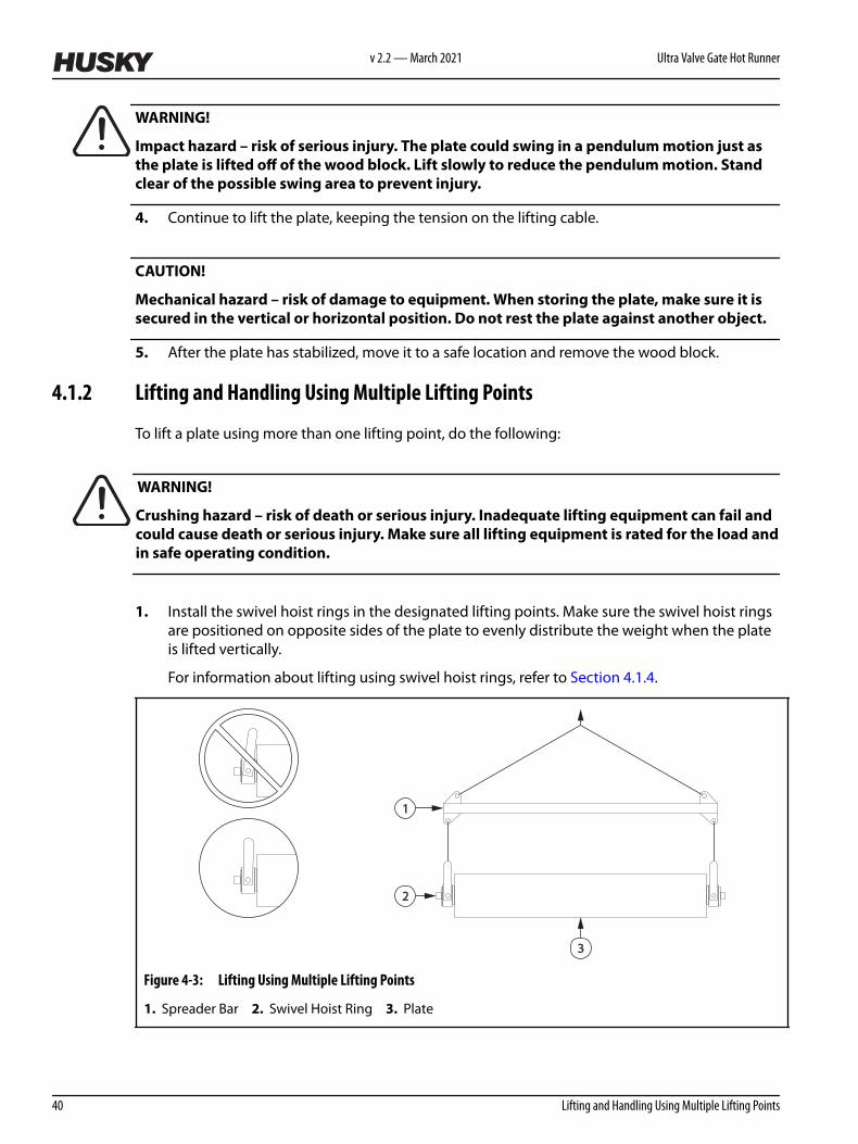
1. Install the swivel hoist rings in the designated lifting points. Make sure the swivel hoist ringsare positioned on opposite sides of the plate to evenly distribute the weight when the plateis lifted vertically.
For information about lifting using swivel hoist rings, refer to Section 4.1.4.
2
1
3
Figure 4-3: Lifting Using Multiple Lifting Points
1. Spreader Bar 2. Swivel Hoist Ring 3. Plate
v 2.2 — March 2021 Ultra Valve Gate Hot Runner
40 Lifting and Handling Using Multiple Lifting Points

2. Connect the swivel hoist rings to an overhead lifting device. Use a spreader bar if either ofthe following conditions occur:
• The pivot angle of any swivel hoist ring exceeds 90°.• The angle of lifting cables, slings or chains is less than 45°.
3. Lift the plate and move it to a safe location.
4.1.3 Lifting Using a Lift Bar
To properly lift plates and assemblies using a lift bar, do the following:
NOTE:
For the installation locations of the lift bars, refer to the hot runner for the markings “Lift Bar Only”or to the assembly drawings.
NOTE:
The maximum weight the bar can lift is stamped on the Husky lift bar. If using a lift bar that is notprovided by Husky, make sure the lift bar is suitably rated for the weight of the mold/hot runnerassembly.
1. Install the lift bar to the lifting holes on the top of the component.
1
2
3
Figure 4-4: Lifting with a Lift Bar
1. Swivel Hoist Ring 2. Lift Bar 3. Screw
2. Torque the hoist ring to the specified value. Refer to Section 3.7 for torque requirements.3. Attach a suitable overhead lifting device to the swivel hoist ring and lift the plate or plate
assembly vertically.4. While the mold and hot runner are in operation, store the Husky provided lifting equipment
together and in a readily accessible area.
Hot Runner Service Manual v 2.2 — March 2021 Installation and Removal
Lifting and Handling 41

4.1.4 Lifting Using Swivel Hoist Rings
When using swivel hoist rings, remember the following:
• For the installation locations of the swivel hoist rings, refer to the hot runner for the markings“Hoist Ring Only” or to the assembly drawings.
• Always make sure the swivel hoist ring is properly torqued before lifting.• Make sure the swivel hoist ring used can support the weight of the plate or component at
the chosen angle of attack.• Do not lift more than the rated capacity.• Depending upon the sling angle, the applied load may be more than the weight being lifted.
Two point lifting of a 1000 kg (2000 lb) weight, with a sling angle of 30°, will result in anapplied load of 1000 kg (2000 lb) to each hoist ring.
• After installation, make sure the hoist ring swivels and pivots freely in all directions. The sideof the ring must not contact anything.
• After installation and during operation, store the Husky provided lifting equipment togetherand in a readily accessible area.
• Never use a hook or other lifting device which will pry or open the “U” shaped bar on center-pull hoist rings.
• Screws must be tightened to the recommended torque values.• Do not apply shock loads. When lifting, apply force gradually.• Do not use spacers between the hoist ring bushing and the work piece surface.• The work piece surface must be flat, providing complete contact for the hoist ring bushing.
Metric and Imperial swivel hoist rings are available through your nearest Husky Parts DistributionCenter.
Swivel hoist rings purchased from other suppliers must meet or exceed the followingspecifications.
Table 4-1: General Hoist Ring Specifications
Category Specification
Material 4140 certified aircraft quality
Type Forged hoist ring
Finish Phosphate per DOD-P-16232F
Safety Factor 5:1
Swivel Pivot 180° and swivel 360°
Thread ISO 261 and ISO 965 - Coarse
Surface Magnetic particle inspected (ASTM E709-80)
Certification Individual certificate of conformance with the serial number specified on the hoist ringfor traceability
v 2.2 — March 2021 Ultra Valve Gate Hot Runner
42 Lifting Using Swivel Hoist Rings

Table 4-2: Specifications for Metric Coarse Swivel Hoist Rings
Part Number Rated Capacity[1] Torque Thread ØMinimum FullThread Depth
Pitch
2761800 1050 kg (2315 lb) 37 N·m (27 lbf·ft) M12 24 1.75
2770570 1900 kg (4189 lb) 80 N·m (59 lbf·ft) M16 32 2.00
2502267 4200 kg (9259 lb) 311 N·m (229 lbf·ft) M24 48 3.00
536013 7000 kg (15432 lb) 637 N·m (470 lbf·ft) M30 60 3.50
2761801 11000 kg (24250 lb) 1085 N·m (800 lbf·ft) M36 72 4.00
2761803 12500 kg (27558 lb) 1085 N·m (800 lbf·ft) M42 84 4.50
[1] Minimum rated capacity at any pull angle (between 0° horizontal pull and 90° vertical pull)
Table 4-3: Specifications for Inch UNC Swivel Hoist Rings
Part Number Rated Capacity[2] Torque Thread ØMinimum FullThread Depth
Pitch
2732764 1130 kg (2500 lb) 38 N·m (28 lbf·ft) 1/2 1.0 13
2732765 2260 kg (5000 lb) 135 N·m (100 lbf·ft) 3/4 1.5 10
2760517 4530 kg (10000 lb) 310 N·m (229 lbf·ft) 1 2.0 8
2732766 6800 kg (15000 lb) 640 N·m (472 lbf·ft) 1 1/4 2.5 7
2732767 10880 kg (24000 lb) 1080 N·m (797 lbf·ft) 1 1/2 3.0 6
[2] Minimum rated capacity at any pull angle (between 0° horizontal pull and 90° vertical pull)
4.2 Mounting Methods
Each hot runner is designed to be mounted to the machine using a specific method. Thefollowing describes the various methods that can be used.
4.2.1 Direct Bolting
The direct bolting method uses screws to secure the hot runner to the stationary platen. Thescrews are either installed through the hot runner into threaded holes in the stationary platen, orthrough the stationary platen into threaded holes in the hot runner.
In this method, the screws are able to carry the maximum possible load while resisting theopening force of the mold.
When using the direct bolting method, adhere to the following guidelines:
Hot Runner Service Manual v 2.2 — March 2021 Installation and Removal
Lifting and Handling 43

• All screws must be lubricated.• The size, quantity and spacing of the screws must be suitable for the machine.
CAUTION!
Crushing hazard – risk of damage to equipment. Screws used to secure the hot runnerto the stationary platen must meet specific requirements. Only use the screwsspecified in the assembly drawings. Failure to use these screws could result inequipment damage.
• Make sure only the screws specified in the assembly drawings are used.• Torque each screw starting from the center of the hot runner and working outwards.
CAUTION!
Mechanical hazard – risk of damage to equipment. Air impact guns could produceexcessive torque and damage the hot runner. Use only a torque wrench to install thehot runner.
• Use a torque wrench to install the screws and verify the torque.
4.2.2 Clamping
The clamping method uses clamps to hold the hot runner to the stationary platen. The clamps aresecured to the stationary platen with screws and hold the hot runner at the operator and non-operator side clamp slots.
In this method, the clamps must be properly secured to prevent the hot runner from slipping. Thismay cause damage as the mold closes or cause the mold and hot runner to fall completely fromthe stationary platen.
WARNING!
Crushing hazard – risk of serious injury, death and/or damage to the hot runner. Clampscould loosen allowing the mold and hot runner to slip or fall completely from the stationaryplaten. Make sure the type, quantity, size and position of the clamps is sufficient formounting the mold and hot runner.
IMPORTANT!
Husky assumes no responsibility for the type, quantity, size or position of the clampingequipment used and does not recommend the clamping method for securing the hot runner tothe machine. It is the responsibility of the customer to make sure the clamping equipment and itsinstallation is adequate for safely securing the hot runner.
Whenever possible, use the direct bolting method. Refer to Section 4.2.1 for more information.
v 2.2 — March 2021 Ultra Valve Gate Hot Runner
44 Clamping

When using the clamping method, adhere to the following guidelines:
• Make sure the screws used to secure the clamps to the stationary platen are torqued.• A sufficient number of clamps must be used to safely secure the mold and hot runner.• The clamps must be positioned as close as possible to each other.• Verify with the clamp supplier the number of clamps to use, the position and the required
torque.• Only use high strength screws with a minimum yield strength of 690 MPa (100000 psi)• Inspect and torque the clamps regularly.
4.2.3 Quick Mold Changers and Clamping Systems
Refer to the quick mold changer or clamping system manufacturer’s documentation forinstallation information.
IMPORTANT!
Any quick mold changer or clamping system must be interlocked appropriately with themachine’s logic and guarding interlock system.
4.3 Removing and Installing the Hot Runner
The following procedures describe how to remove and install the hot runner.
4.3.1 Installing the Hot Runner
IMPORTANT!
Hot runners may not be put into service in a machine that does not comply with the provisions ofMachinery Directive 2006/42/EC, as amended, and with the regulations transposing it intonational law.
To install the hot runner in the machine, do the following:
1. Verify the machine nozzle orifice and radius match the sprue bushing in the hot runner.Processing problems can occur if the two systems do not match.
2. Make sure the clamp is open to maximum daylight.3. Lock out and tag the machine and controller (if equipped). Refer to Section 2.5 for more
information.
Hot Runner Service Manual v 2.2 — March 2021 Installation and Removal
Mounting Methods 45

CAUTION!
Mechanical hazard – risk of damage to equipment. An improperly leveled machine couldmake the hot runner installation difficult and cause premature component wear. Make surethe machine is leveled before installing the hot runner.
4. Make sure the machine is level and the platens are parallel. Refer to the machinemanufacturer’s documentation for more information.
NOTE:
The cavity plate may be attached to the hot runner during installation.
5. Install or remove the cavity plate as needed. Refer to Section 6.6 for more information.6. Using a protective spray and a lint-free cloth, clean all mounting surfaces on the hot runner
and stationary platen. Refer to Section 3.5 for a list of recommended lubricants.
Remove any hard dirt, nicks or burrs with a medium India stone (240 grit oil stone).7. Spray all mounting surfaces on the hot runner and stationary platen with a protective spray.
Refer to Section 3.5 for a list of recommended lubricants.8. Inspect all fittings and electrical connections on the hot runner for damage. Repair or replace
as necessary.
WARNING!
Crushing hazard – risk of death or serious injury. Inadequate lifting equipment could failand cause death or serious injury. Make sure all lifting equipment is rated for the load andin safe operating condition.
9. Install and torque the lift bar to the hot runner. Refer to Section 4.1.3 for more information.
WARNING!
Crushing hazard – risk of death or serious injury. Inadequate lifting equipment could failand cause death or serious injury. Make sure all lifting equipment is rated for the load andin safe operating condition.
10. Attach an overhead lifting device to the lift bar and lift the hot runner over the mold area.Make sure the locating ring faces the stationary platen.
11. Lower the hot runner into the mold area. If necessary, rotate the assembly 90° to fit itbetween the tie bars.
12. Align the locating ring with the sprue nozzle and position the backing plate against thestationary platen.
v 2.2 — March 2021 Ultra Valve Gate Hot Runner
46 Removing and Installing the Hot Runner

CAUTION!
Crushing hazard – risk of damage to equipment. Screws used to secure the hot runner tothe stationary platen must meet specific requirements. Only use the screws specified in theassembly drawings. Failure to use these screws could result in equipment damage.
13. Secure the backing plate to the stationary platen. Refer to Section 4.2 for information aboutvarious mounting methods.
14. Disconnect the overhead lifting device and remove the lift bar.
CAUTION!
Mechanical hazard – risk of damage to equipment. When installing hoses, make sure theyare not routed over edges or positioned where they could rub together, causing motion orvibration damage.
15. Connect the cooling hoses to the hot runner.16. Connect the supplied heater and thermocouple cables to the designated ports on the hot
runner and controller.
CAUTION!
Mechanical hazard – risk of damage to equipment. When installing cables, make sure theyare not routed over edges, positioned where they could rub together, or near moving parts.The resulting motion or vibrations could damage the cable insulation.
17. Arrange the cables, using clamps or ties if necessary, to avoid contact with moving parts orsharp edges.
WARNING!
Poison hazard – risk of death or serious injury. The mold may have been sprayed with a rustinhibitor that could be toxic if ingested. To avoid contamination of food packagingproducts, this inhibitor must be completely removed. Clean all molding surfaces with anappropriate molding surface cleaner and discard all molded products until all traces of therust inhibitor are removed.
18. If the cavity plate is installed on the hot runner, remove the rust inhibitor from all moldingsurfaces on the cavity plate using an appropriate molding surface cleaner.
19. Remove all locks and tags.
4.3.2 Removing the Hot Runner
To remove the hot runner from the machine, do the following:
Hot Runner Service Manual v 2.2 — March 2021 Installation and Removal
Removing and Installing the Hot Runner 47
WARNING!
Hot resin spray hazard – risk of death or serious injury. Residual pressure from gases in thehot runner could cause hot resin to spray from the nozzle tips when released. Make sure thevalve gates are open when turning off the heaters to relieve pressure in the hot runner.
CAUTION!
Mechanical hazard – risk of damage to the hot runner. Do not actuate the valve stems whenthe hot runner is cold. Damage to the valve stems, pistons and/or shear pins (if equipped)could occur. Make sure the hot runner is at operating temperature before actuating thevalve stems.
1. Make sure the valve gates are open.2. Open the mold and turn off all heaters.3. Cool the hot runner by running coolant through it until the nozzles and manifold are at room
temperature (< 25 °C or < 77 °F). This may take 1/2 to 4 hours depending on the size of thehot runner.
4. Lock out and tag the machine and controller (if equipped). Refer to Section 2.5 for moreinformation.
5. Purge all cooling water from the cooling hoses to minimize the risk of a coolant spill should ahose come loose during maintenance. Refer to the machine manufacturer’s documentationfor more information.
6. Disconnect all cooling hoses from the hot runner.7. Disconnect all electrical cables and connectors from mold and hot runner.
WARNING!
Crushing hazard – risk of death or serious injury. Inadequate lifting equipment could failand cause death or serious injury. Make sure all lifting equipment is rated for the load andin safe operating condition.
8. Install and torque the lift bar to the hot runner. Refer to Section 4.1.3 for more information. 9. Attach an overhead lifting device to the hoist ring and lift only until the lifting chain has a
slight tension on it.10. Disconnect the backing plate from the stationary platen starting on the non-operator side,
followed by the operator side.11. Lift the hot runner out of the clamp. If necessary, rotate the hot runner 90° to fit it between
the tie bars.
WARNING!
Crushing hazard – risk of death or serious injury. Do not work under suspended loads. Toprevent injury, install safety blocks.
v 2.2 — March 2021 Ultra Valve Gate Hot Runner
48 Removing and Installing the Hot Runner

12. Install feet on the bottom of the hot runner to protect the hose fittings.
CAUTION!
Mechanical hazard – risk of damage to equipment. Store and secure the hot runner in thevertical or horizontal position. Do not rest the assembly against another object.
CAUTION!
Mechanical hazard – risk of damage to the hot runner. The hot runner must be set onsupports if it is laid down horizontally, such as on a work bench. Damage to the nozzle tips,sprue bar and/or wires could occur.
13. Move the hot runner to a safe location.
Hot Runner Service Manual v 2.2 — March 2021 Installation and Removal
Removing and Installing the Hot Runner 49

v 2.2 — March 2021 Ultra Valve Gate Hot Runner
50

Chapter 5 Startup and Operation
This chapter describes how to safely startup and operate the hot runner. Follow these instructionsalong with any in the machine manufacturer’s documentation.
NOTE:
If the hot runner is installed in a Husky machine, refer to the startup instructions in the machinemanufacturer’s documentation.
To startup the hot runner for operation, perform the following procedures in order:
Step Task Reference
1 Prepare the hot runner Section 5.1
2 Heat up the mold, hot runner and machine Section 5.2
3 Precharge the hot runner with resin Section 5.3
4 Produce test parts Section 5.4
IMPORTANT!
The mold and hot runner must be installed properly by qualified personnel before productionbegins.
5.1 Preparing the Hot Runner
To prepare the hot runner for startup, do the following:
1. Lock out and tag the machine and controller (if equipped). Refer to Section 2.5 for moreinformation.
2. Make sure the mold and hot runner are installed properly.3. Make sure the heaters and thermocouples are connected to the machine or a controller.4. Make sure the resin type in the machine matches the required type indicated on the hot
runner nameplate. Refer to Section 1.7 for more information about the nameplate.
Hot Runner Service Manual v 2.2 — March 2021 Startup and Operation
Preparing the Hot Runner 51

CAUTION!
Mechanical hazard – risk of damage to the hot runner. In the event of water leaking into thehot runner, the nozzle heaters could fail. Make sure all water is removed before starting upthe hot runner.
5. Using compressed air, remove any water around the nozzle tips and parting lines.6. Make sure all safety latches have been removed from the mold and hot runner.7. Remove all locks and tags.
CAUTION!
Mechanical Hazard – Risk of damage to hot runner. Dry cycling the valve stems on a hotrunner system is not recommended. Dry cycling can damage the valve stems, nozzle tips,and gate steel. If dry cycling is required for inspection of the hot runner, this should be keptto a minimum. If a long dry cycle of the injection molding machine is required, then it is notrecommended to actuate valve stems during this operation.
5.2 Heating Up the Hot Runner, Mold and Machine
To bring the hot runner, mold and machine up to operating temperature, do the following:
1. If equipped, make sure the dryer is enabled and adjusted to the proper operatingtemperature.
2. Make sure the water chiller is enabled and adjusted to the proper operating temperature.3. If equipped, make sure the mold enclosure de-humidifier, air compressor and water tower
supplies are enabled.4. Check the air pressure settings for the machine.5. Make sure the compressed air for the mold is turned off. If the compressed air is left on as the
hot runner heats up, air will leak from the system. This will cool the hot runner and delay thestartup.
6. Slowly open the clamp to full shutheight.7. Turn on the hot runner cooling system.
WARNING!
Hot resin spray hazard – risk of death or serious injury. Overheated resin can generatepressurized gas that when suddenly released can cause material to spray out. Do not allowresin to overheat. If the startup process is interrupted, turn off all barrel heaters and retractthe injection unit to allow the hot runner to vent between the machine nozzle and thesprue bushing. For extended delays, follow the machine manufacturer’s and resin supplier’sprocedures for machine shutdown.
8. Turn on the machine barrel heaters and allow them approximately 1/2 to 1 1/2 hours toreach operating temperature, depending on the size of the injection unit.
v 2.2 — March 2021 Ultra Valve Gate Hot Runner
52 Heating Up the Hot Runner, Mold and Machine

9. If equipped, turn on the controller.
CAUTION!
Mechanical hazard – risk of damage to the hot runner. Never operate the hot runner outsideof the melt and mold temperatures indicated on the nameplate. Internal resin leakage orcomponent damage could occur.
10. Set the temperature of the main manifold heaters, cross manifold heaters (if equipped) andsprue heater to the melt temperature indicated on the nameplate. Refer to Section 1.7 formore information about the nameplate.
WARNING!
Hot resin spray hazard – risk of death or serious injury. The sprue heater must be turned onwhen the manifold heaters are turned on. Failure to do so could result in the generation ofdangerous pressure levels in the manifold, resulting in the sudden release of hot resin.
11. Turn on the main manifold heaters, cross manifold heaters (if equipped) and sprue heater (ifequipped) zones. Wait for the heaters to reach operating temperature. Wait an additional 10minutes or more of soak time to make sure the resin has reached the operating temperature.
12. Make sure the main manifold heaters and the cross manifold heaters (if equipped) reach theset temperature.
13. Turn on the transfer bushing heaters (if equipped) zones. Wait for the heaters to reach theoperating temperature and then wait an additional 10 minutes or more of soak time to makesure the resin has reached the operating temperature.
14. Open the process material feed. Refer to the machine manufacturer’s documentation formore information.
5.3 Precharging the Hot Runner
To precharge the hot runner with resin, do the following:
1. Close the clamp and apply tonnage.
WARNING!
Hot resin spray hazard – risk of death or serious injury. Molten resin under high pressurecan suddenly release and spray out from the machine nozzle. Before purging the barrel orshooting pot, clear the area of all non-essential personnel and wear personal protectiveequipment consisting of a heat-resistant coat, heat-resistant gloves and a full face shieldover safety glasses.
2. Purge the injection unit. Refer to the machine manufacturer’s documentation for moreinformation.
Hot Runner Service Manual v 2.2 — March 2021 Startup and Operation
Heating Up the Hot Runner, Mold and Machine 53

3. Clean the machine nozzle, stationary platen and purge guard of any resin deposits. Refer tothe machine manufacturer’s documentation for more information.
4. Make sure the machine nozzle is firmly seated against the sprue bushing.5. Turn on the nozzle heaters and allow them approximately 5 to 7 minutes before mold
operation to reach operating temperature.
CAUTION!
Mechanical hazard – risk of damage to equipment. Do not allow nozzle tips to stayenergized for more than 10 minutes without injecting resin. Resin residing in the nozzle tiparea will degrade.
6. While the nozzle heaters are reaching operating temperature, do the following:a. Turn on the extruder screw to start plasticizing the resin.b. Repeat step 2 to step 3.
7. Move the machine nozzle forward until it is firmly seated against the sprue bushing.
NOTE:
The hot runner channels are properly filled with resin when the injection piston stops beforemaking contact with the injection housing.
8. Inject resin into the hot runner until the injection piston stops. The piston must stop before itmakes contact with the injection housing. If the piston makes contact with the injectionhousing, inject resin again.
9. Once the injection piston stops, start the extruder screw and make sure it retracts fully.
5.4 Producing Test Parts
To produce test parts that will verify the settings and functions for the hot runner and machine,do the following:
1. Make sure the nozzle heaters have not timed out. If the nozzle heaters have timed out, dothe following:a. Enable the heaters and wait approximately 5 to 7 minutes to reach operating
temperature.b. Purge the injection unit. Refer to the machine manufacturer’s documentation for more
information.c. Clean the machine nozzle, stationary platen and purge guard of any resin deposits.
Refer to the machine manufacturer’s documentation for more information.2. Close the clamp and apply tonnage.3. Make sure the machine nozzle is firmly seated against the sprue bushing.4. Reduce the injection pressure to 70 bar (1000 psi) .5. Disable all ejector functions to prevent the machine from automatically ejecting parts.6. Cycle the machine once in normal mode to produce a set of parts.
v 2.2 — March 2021 Ultra Valve Gate Hot Runner
54 Producing Test Parts

7. Check that all parts have been properly molded.8. Manually control the ejector functions to eject the parts.9. If all cavities are producing parts, reset the injection pressure to the recommended value.10. Cycle the machine four times in normal mode to produce parts. This will remove any air
trapped in the resin.11. Visually inspect the last set of parts to verify the part quality. Repeat step 10 until the part
quality is satisfactory.12. Enable the ejector functions.13. If equipped, enable the product handling equipment.14. Cycle the machine 10 times in semi-cycle mode. During each cycle, if equipped, make sure
the product handling equipment properly transfers the parts to the conveyor.15. Enable the auto-cycle mode for the machine and begin production.
Hot Runner Service Manual v 2.2 — March 2021 Startup and Operation
Producing Test Parts 55

v 2.2 — March 2021 Ultra Valve Gate Hot Runner
56
Chapter 6 Maintenance
This chapter describes the maintenance tasks required to maintain the hot runner. Refer to Section 6.1 for a full list of maintenance procedures.
NOTE:
Unless specified otherwise, all bolts, screws, fittings and other hardware should be torqued to thevalues listed on the assembly drawings specific to the hot runner.
WARNING!
Risk of injury. When entering the molding area, personal protective equipment must bewarn to guard against burns, abrasions, hearing, foot, eye, and face hazards and any otherprocedure specific hazards listed in the manual.
WARNING!
Chemical hazard - Some of the chemicals used when servicing or maintaining Huskyequipment are potentially hazardous and could cause injury and illness. Before storing,handling, or working with any chemical or hazardous material, thoroughly read andunderstand each applicable Material Safety Data Sheet (MSDS), use recommendedpersonal protective equipment and follow the manufacturer’s instructions.
IMPORTANT!
The procedures contained in this chapter were written for a standard hot runner and do not takespecial options into consideration.
6.1 Scheduled and Non-Scheduled Maintenance
Throughout the life of the mold and hot runner, various systems and components will need to beinspected and serviced on a scheduled or non-scheduled basis.
There are two types of maintenance procedures:
• Preventive procedures are performed at scheduled intervals• Service procedures are performed when required
Hot Runner Service Manual v 2.2 — March 2021 Maintenance
Scheduled and Non-Scheduled Maintenance 57

6.1.1 Preventive Maintenance
The following procedures must be performed when either the interval or cycle count is reachedas part of the recommended preventive maintenance program for the mold and hot runner.
Interval Cycles Task Description Reference
Every 6 Months 800,000 Test the hot runner heaters Section 6.5
Every 12 Months 1,600,000 Remove excess resin from the manifold plate Section 6.27
Inspect the valve stem and piston assemblies Section 6.12
Every 18 Months 2,000,000 Replace the double delta seals Section 6.13
6.1.2 Service Procedures
The following procedures are to be performed only when needed.
Procedure Reference
Adjusting the thermocouple wire length Section 6.24
Changing the resin color Section 6.2
Extending nozzle and sprue heater wire leads Section 6.3
Measuring preload Section 6.4
Removing insulating gate bubbles Section 6.19
Removing resin from the hot runner Section 6.26
Removing resin from the manifold plate Section 6.27
Removing and installing manifold bushings Section 6.20
Removing and installing manifolds Section 6.9
Removing and installing nozzle heaters Section 6.17
Removing and installing nozzle housings Section 6.16
Removing and installing nozzle tip insulators Section 6.18
Removing and installing nozzle tips Section 6.14
Removing and installing the backing plate Section 6.7
Removing and installing the cavity plate Section 6.6
Removing and installing the center plate (if equipped) Section 6.8
v 2.2 — March 2021 Ultra Valve Gate Hot Runner
58 Preventive Maintenance

Procedure Reference
Removing and installing the sprue bushing Section 6.22
Removing and installing the sprue heater Section 6.21
Removing and installing transfer bushings (if equipped) Section 6.23
Removing and installing valve stems Section 6.12
Removing and installing VG-LX/EX backup pads Section 6.10
Removing and installing VG-SX cylinders Section 6.11
Removing air and water plugs Section 6.25
6.2 Changing the Resin Color
To change the color of the resin, do the following:
1. Lock out and tag the machine and controller (if equipped). For machine lockout and tagprocedures refer to the machine documentation.
2. Remove all traces of the original resin from the material feed equipment.3. Depending on application restrictions, add one of the following to the material feed
equipment to reduce the cleaning time required:
• Purge compound• Natural (uncolored) resin• New colored resin
4. Remove all locks and tags.5. Power up the machine and turn on the controller (if equipped).
WARNING!
Hot resin spray hazard – risk of serious injury. Molten resin under high pressure cansuddenly release and spray out from the machine nozzle. Before purging the injection unit,clear the area of all non-essential personnel and wear personal protective equipmentconsisting of a heat-resistant coat, heat-resistant gloves and a full face shield over safetyglasses.
6. Purge the injection unit until all traces of the old color are eliminated. For instructions, referto the machine manufacturer’s documentation.
7. Increase the injection speed to the maximum value allowed by the application.8. Reduce the hold time and cooling time to the minimum values allowed by the application.9. Increase the temperature of the hot runner nozzle tips, manifold and sprue by 20 to 30 °C (68
to 86 °F) .
Hot Runner Service Manual v 2.2 — March 2021 Maintenance
Scheduled and Non-Scheduled Maintenance 59

10. Repeat step 3 to replenish the material feed system, if required.11. Produce a series of test parts until all traces of the old color are eliminated.12. When the color change is complete, decrease the temperature of the nozzle tips, manifold
and sprue by 20 to 30 °C (68 to 86 °F) .13. Return the hold time, cooling time and injection speed back to their original values.14. Fill the material feed equipment with the new resin.
6.3 Extending Nozzle and Sprue Heater Wire Leads
The following procedure describes how to install the nozzle and sprue heater lead splice kit (P/N4047310) to extend the length of the nozzle and sprue heater wires. This kit may be required onsystems where the wire leads are not long enough to reach the electrical connectors.
IMPORTANT!
This procedure is only for nozzle and sprue heater leads when standard lead lengths are not longenough.
This procedure is not to be used for extending thermocouple wire leads. Splicing thermocouplewires will cause false and/or erratic temperature readings.
When required, standard thermocouples are available with longer wire lead lengths.
To install the kit, do the following:
1. Strip the ends of the wire and the wire supplied with the kit until 6 mm (0.2 in) of wire lead isexposed on both.
2. Slide heat shrink tubing over the butt connector. Make sure the butt connector is centered inthe tubing.
Figure 6-1: Installing the Heat Shrink Tubing
1. Butt Connector 2. Heat Shrink Tubing
3. Insert the wires into both ends of the butt connector until no wire lead is visible.
v 2.2 — March 2021 Ultra Valve Gate Hot Runner
60 Extending Nozzle and Sprue Heater Wire Leads

Figure 6-2: Butt Connector
4. Using a crimping tool, crimp one end of the butt connector at a time.5. Shrink the tubing using a heat gun.6. Seal the ends of the heat shrink tubing where the tubing meets the wire lead insulation.
Figure 6-3: Completed Wire Lead Extension
6.4 Measuring Preload
Preload measurements from various sections of the hot runner must be taken and verified beforethe plates are assembled and when the hot runner is at room temperature (< 25 °C or < 77 °F).Damage to the plates, backup pads or cylinders, and nozzle stacks could occur if the preloadmeasurements are not within the allowed tolerance.
IMPORTANT!
Always measure preload in more than one section of the hot runner to make sure preload isconsistent.
Maintaining proper preload will help prevent molten plastic from leaking inside the hot runner.
Perform the following procedures as applicable to determine the preload on the manifoldsand/or cross manifold (if equipped):
Procedure Reference
Measuring Preload for Manifolds in VG-LX/EX Systems Section 6.4.1
Measuring Preload for Manifolds in VG-SX Systems Section 6.4.2
Measuring Preload for Cross Manifolds (If Equipped) in Two Plate System Section 6.4.3
Measuring Preload for Cross Manifolds (If Equipped) in Three Plate System Section 6.4.4
Hot Runner Service Manual v 2.2 — March 2021 Maintenance
Extending Nozzle and Sprue Heater Wire Leads 61

6.4.1 Measuring Preload for Manifolds in VG-LX and EX Systems
To measure the preload on a manifold, do the following:
CAUTION!
Mechanical hazard – risk of damage to the hot runner. Do not tighten the screws that securethe manifolds to reduce the preload values. These screws should be hand tightened andthen turned counter-clockwise 1/4 turn before preload measurements are taken.
1. Make sure the screws that secure the manifold to the manifold plate are hand-tightened andthen turned counter-clockwise 1/4 turn.
2. Determine the height of the backup pads from the assembly drawings. Record the value asmeasurement A.
3. Using a depth micrometer, measure the distance from the top face of the manifold plate tothe face of the manifold. Record this value as measurement B.
Figure 6-4: Measuring Preload
4. Complete the following calculation to determine the preload:
A - B = Preload5. Repeat step 2 to step 4 for all other corners of the manifold to make sure the preload
measurements are consistent.6. Compare the preload values to the C or C1 dimension values listed on the Tip Chart on the
assembly drawings.
If the measured preload is not within the tolerances given on the Tip Chart, check allmeasurements and review the assembly for obstructions or debris. Repeat step 2 to step 6until the preload measurements are within tolerance.
6.4.2 Measuring Preload for Manifolds in VG-SX Systems
To measure the preload on a manifold, do the following:
v 2.2 — March 2021 Ultra Valve Gate Hot Runner
62 Measuring Preload for Manifolds in VG-LX and EX Systems

CAUTION!
Mechanical hazard – risk of damage to the hot runner. Do not tighten the screws that securethe manifolds to reduce the preload values. These screws should be hand tightened andthen turned counter-clockwise 1/4 turn before preload measurements are taken.
1. Make sure the screws that secure the manifold to the manifold plate are hand-tightened andthen turned counter-clockwise 1/4 turn.
2. Determine the height of the cylinders from the assembly drawings. Record the height asmeasurement A.
3. Using a depth micrometer, measure the distance from the top face of the manifold plate tothe face of the manifold(s). Subtract this value from the height of the cylinders and recordthe measurement as measurement B.
C
BA
2
3
1
Figure 6-5: Measuring Preload
1. Cylinder 2. Backing Plate 3. Manifold Plate
4. On the backing plate, measure the distance from the manifold-plate-to-backing-platesurface to the sealing surface in the cylinder bore. Record the distance as measurement C.
NOTE:
The sealing surface is where the cylinder contacts the backing plate.
5. Complete the following calculation to determine the preload:
A - (B + C) = Preload6. Repeat step 2 to step 5 for all other corners of the manifold to make sure the preload
measurements are consistent.7. Compare the preload values to the C or C1 dimension values listed on the Tip Chart on the
assembly drawings.
If the measured preload is not within the tolerances given on the Tip Chart, check allmeasurements and review the assembly for obstructions or debris. Repeat step 2 to step 7until the preload measurements are within tolerance.
Hot Runner Service Manual v 2.2 — March 2021 Maintenance
Measuring Preload 63

6.4.3 Measuring Preload for Cross Manifolds in Two Plate Systems (If Equipped)
To measure the preload on a cross-manifold, do the following:
CAUTION!
Mechanical hazard – risk of damage to the hot runner. Do not tighten the screws that securethe manifolds to reduce the preload values. These screws should be hand tightened andthen turned counter-clockwise 1/4 turn before preload measurements are taken.
1. Make sure the screws that secure the cross manifold to the manifolds are hand-tightenedand then turned counter-clockwise 1/4 turn.
2. Remove the C-rings, if equipped.3. Using a depth micrometer, measure the distance from the top face of the cross manifold to
the top face of the backup pad (LX or EX) or cylinder (SX). Record value as measurement A.
2
1
3A
Figure 6-6: Measurement A
1. Backup Pad or Cylinder 2. Manifold 3. Cross Manifold
4. Make sure the backing plate is laying on a work bench with the pocket facing up.5. Using a depth micrometer, measure the distance from the top face of the backing plate to
the face inside the bore where the backup plate spring pack will make contact. Record valueas measurement B.
v 2.2 — March 2021 Ultra Valve Gate Hot Runner
64 Measuring Preload for Cross Manifolds in Two Plate Systems (If Equipped)

2
1
B
Figure 6-7: Measurement B
1. Backing Plate 2. Backup Plate Spring Pack
6. Complete the following calculation to determine the preload:
A - B = Preload7. Repeat step 1 to step 6 for all other corners of the cross manifold to make sure the preload
measurements are consistent.8. Compare the preload measurements to the C2 dimension value listed on the Tip Chart on
the assembly drawings.
If the measured preload is not within the tolerances given on the Tip Chart, check allmeasurements and review the assembly for obstructions or debris. Repeat step 1 to step 8until the preload measurements are within tolerance.
6.4.4 Measuring Preload for Cross Manifolds in Three Plate Systems (If Equipped)
To measure the preload on a cross-manifold, do the following:
CAUTION!
Mechanical hazard – risk of damage to the hot runner. Do not tighten the manifold or crossmanifold hold down bolts to reduce the preload values. Manifold and cross manifold holddown bolts should be hand tightened and then turned counter-clockwise 1/4 turn beforepreload measurements are taken.
1. Using a depth micrometer, measure the distance from the top of the transfer bushing to thetop face of the center plate. Record the value as measurement A.
Hot Runner Service Manual v 2.2 — March 2021 Maintenance
Measuring Preload 65

A1
2
3
Figure 6-8: Measuring Distance A
1. Transfer Bushing 2. Center Plate 3. Manifold Plate
2. Using a depth micrometer, measure the distance from the top face of the backing plate tothe face inside the bore where the backup plate spring pack will make contact. Record valueas measurement B.
2
1
B
Figure 6-9: Measurement B
1. Backing Plate 2. Backup Plate Spring Pack
3. Measure the thickness of the center plate and record the value as measurement C.4. Determine the cold clearance between the cross manifold and the transfer bushing listed on
the Tip Chart in the assembly drawings. Refer to Section 6.4.1 for more information. Recordthe value as measurement D.
5. Complete the following calculation to determine the preload:
A - (B + C + D) = Preload6. Repeat step 1 to step 5 for all other corners of the cross manifold to make sure the preload
measurements are consistent.7. Compare the preload measurements to the C2 dimension value listed on the Tip Chart on
the assembly drawings.
If the measured preload is not within the tolerances given on the Tip Chart, check allmeasurements and review the assembly for obstructions or debris. Repeat step 1 to step 7until the preload measurements are within tolerance.
v 2.2 — March 2021 Ultra Valve Gate Hot Runner
66 Measuring Preload

6.5 Testing Heaters
To confirm a heater is functioning properly, do the following:
1. With the heater at or near room temperature, use an ohmmeter to measure the resistancethrough the heater. Refer to the electrical schematic for the required ohms measurement.
The normal tolerance for all heaters is ±15%.
IMPORTANT!
A common problem with heaters is moisture absorption due to the hygroscopic nature of theinsulation. A heater with a low case to center conductor insulation reading (<10K Ω) should bebaked out and retested to determine if moisture was the cause. Contact Husky for moreinformation.
2. Using an ohmmeter, measure the resistance through each lead to ground. A measurementfrom either lead to ground that is below 100K Ω indicates a short to ground. A measurementfrom 100K Ω to 1M Ω is often associated with a wet heater.
A measurement greater than 1M Ω is good.
NOTE:
A short reading can be the result of either a pinched wire or a broken heater element. Inspect thewires first to make sure there are no pinched or damaged lead wires. A heater wire can be spliced,however, this should only be done by a certified electrician. The splice should include dual layerheat shrink tubing with an adhesive inner layer to avoid potential water shorts. The heat shrinkshould be rated for 150 °C (203 °F) minimum.
NOTE:
Refer to the electrical schematics for resistance information.
6.6 Removing and Installing the Cavity Plate
Removing the cavity plate provides access to wiring, nozzle tips, nozzle heaters and gates. Thecavity plate can be removed when the mold and hot runner assembly is in the machine or on awork bench.
CAUTION!
Risk of damage to the sealing surfaces. Hot runner nozzles must be at room temperature(<25 °C or <77 °F) before removing or installing the cavity plate to avoid damage to thesealing surfaces.
Hot Runner Service Manual v 2.2 — March 2021 Maintenance
Testing Heaters 67

6.6.1 Removing the Cavity Plate On a Work Bench
To remove the cavity plate from the hot runner when the assembly is on a work bench, do thefollowing:
NOTE:
The following procedure requires the use of an overhead lifting device. Refer to Section 4.1 forlifting and handling instructions.
CAUTION!
Mechanical hazard – risk of damage to the hot runner. Make sure all valve stems are in theopen position during tool shutdown.
1. Remove the hot runner and cavity plate assembly from the machine and set it on a workbench with the nozzles facing up. Refer to Section 4.3 for more information.
CAUTION!
Mechanical hazard – risk of damage to the nozzle sealing surfaces. The temperature of thenozzle tips must cool to room temperature <25 °C (<77 °F) before the cavity plate isremoved. Damage to the nozzle sealing surfaces will occur if the temperature is too high.
2. Remove the screws that secure the cavity plate to the hot runner.
WARNING!
Crushing hazard – risk of death or serious injury. Inadequate lifting equipment can fail andcould cause death or serious injury. Make sure all lifting equipment is rated for the load andin safe operating condition.
3. Install hoist rings in the designated lifting points marked on the cavity plate.
CAUTION!
Mechanical hazard – risk of damage to the mold and hot runner. Lift the cavity plate slowlyuntil the alignment dowels are cleared. Damage to the cavity plate and/or alignmentdowels could occur.
4. Attach an overhead lifting device to the hoist rings and lift the cavity plate. Use the pry slotsbetween the plate and hot runner to help separate the cavity plate.
v 2.2 — March 2021 Ultra Valve Gate Hot Runner
68 Removing the Cavity Plate On a Work Bench

WARNING!
Crushing hazard – risk of death or serious injury. Do not work under suspended loads. Toprevent injury, install safety blocks.
5. If equipped, install feet on the bottom of the cavity plate to protect the hose fittings.6. Move the cavity plate out of the work area. Store the plate in a location where the plate
cannot fall or tip over.7. If equipped, remove the nozzle tip insulators from the nozzle tips and/or cavity plate. Refer
to Section 6.18 for more information.8. Remove any insulating gate bubbles on the nozzle tips or in the cavity plate gate details.
Refer to Section 6.19 for more information.
6.6.2 Installing the Cavity Plate On a Work Bench
To secure the cavity plate to the hot runner when the assembly is on a work bench, do thefollowing:
NOTE:
The following procedure assumes the cavity plate was removed as described in Section 6.6.1
NOTE:
The following procedure requires the use of an overhead lifting device. Refer to Section 4.1 forlifting and handling instructions.
CAUTION!
Mechanical hazard – risk of damage to the hot runner. Make sure all valve stems are in thestill in the open position prior to installation.
1. Make sure the hot runner is on a work bench with the nozzle tips facing up. The hot runnermust be supported by two blocks.
2. Make sure the nozzle and cavity plate sealing diameters are clean and free of burrs or oil.
Hot Runner Service Manual v 2.2 — March 2021 Maintenance
Removing and Installing the Cavity Plate 69

4
5
2
3
1
Figure 6-10: Cavity and Nozzle Sealing Diameters
1. Nozzle and Cavity Plate Sealing Diameters 2. Gate Bubble 3. Cavity Plate 4. NozzleHousing 5. Manifold Plate
3. Apply a static application grease to the hot runner alignment dowels. Refer to Section 3.5 forinformation about recommended lubricants.
4. If equipped, install a nozzle tip insulator on each nozzle tip. Refer to Section 6.18 for moreinformation.
WARNING!
Crushing hazard – risk of death or serious injury. Inadequate lifting equipment can fail andcause death or serious injury. Make sure all lifting equipment is rated for the load and insafe operating condition.
5. Install hoist rings in the designated lifting points marked on the cavity plate.6. Attach an overhead lifting device to the hoist rings and lift the cavity plate over the hot
runner.
IMPORTANT!
When assembling the cavity plate to the hot runner, special attention should be given topreventing damage to the nozzle tips, valve stems and wires. The cavity plate should mate withthe hot runner without any resistance. If resistance is encountered, remove the plate and checkfor any interference points.
CAUTION!
Mechanical hazard – risk of damage to equipment. Do not force the plate into position asserious damage to the nozzle tips, valve stems and wires can result.
v 2.2 — March 2021 Ultra Valve Gate Hot Runner
70 Removing and Installing the Cavity Plate

CAUTION!
Mechanical hazard – risk of damage to the mold and hot runner. The nozzles and manifoldmust be at room temperature (< 25 °C or < 77 °F) before the cavity plate is connected to thehot runner. Severe damage to the nozzle and cavity plate sealing diameters can result if themold is still hot.
7. Align the cavity plate with the alignment dowels and lower the plate onto the hot runner.Make sure the wires in the wire channels are not pinched between the plates while closing.
8. Disconnect the overhead lifting device and remove the hoist rings.9. Remove the feet from the bottom of the cavity plate.10. Install safety latch bars between the cavity plate and hot runner on both sides of the
assembly. A minimum of two safety latch bars are required.11. Install the screws that secure the cavity plate to the hot runner and torque them to the
specified value. Refer to the manufacturer’s documentation for torque requirements.12. Check the electrical circuit with an ohmmeter to make sure no wires were damaged during
installation. Refer to the electrical schematic to identify each zone.
6.6.3 Removing the Cavity Plate In the Machine
To remove the cavity plate from the hot runner when the assembly is in the machine, do thefollowing:
WARNING!
Hot resin spray hazard – risk of serious injury. Residual pressure from gases in the hotrunner could cause hot resin to spray from the nozzle tips when released. Make sure thevalve gates are open when turning off the heaters to relieve pressure in the hot runner.
CAUTION!
Mechanical hazard – risk of damage to the hot runner. Do not actuate the valve stems whenthe hot runner is cold. Damage to the valve stems could occur.
1. Open the valve gates.2. Cool the mold by running coolant through it until the hot runner nozzles and manifold(s) are
at room temperature (< 25 °C or < 77 °F). This may take 1/2 to 4 hours depending on the sizeof the hot runner.
3. Open the clamp.4. Lock out and tag the machine and controller (if equipped). Refer to Section 2.5 for more
information.5. Purge all cooling water from the cooling hoses to minimize the risk of a coolant spill should a
hose come loose during maintenance. Refer to the machine manufacturer’s documentationfor more information.
Hot Runner Service Manual v 2.2 — March 2021 Maintenance
Removing and Installing the Cavity Plate 71

6. Install safety latch bars between the cavity plate and hot runner on both sides of theassembly. A minimum of two safety latch bars are required.
1
Figure 6-11: Latching the Cavity Plate to the Hot Runner (Overhead View)
1. Safety Latch Bar
CAUTION!
Mechanical hazard – risk of damage to the nozzle sealing surfaces. The temperature of thenozzle tips must cool to room temperature <25 °C (<77 °F) before the cavity plate isremoved. Damage to the nozzle sealing surfaces will occur if the temperature is too high.
7. Remove the screws that secure the cavity plate to the hot runner.8. Remove all locks and tags.9. Reduce the clamp opening and closing speed.10. Slowly close the clamp.11. Lock out and tag the machine and controller (if equipped).12. Remove all safety latch bars.
CAUTION!
Mechanical hazard – risk of damage to the machine, mold and hot runner. Make sure thehoses attached to the cavity plate are long enough to allow latching without damaging thehoses. In some cases it may be necessary to relieve residual pressure in the system and thendisconnect the hoses.
13. Install safety latch bars between the cavity plate and core plate on both sides of theassembly. A minimum of two safety latch bars are required.
14. Remove all locks and tags.
v 2.2 — March 2021 Ultra Valve Gate Hot Runner
72 Removing and Installing the Cavity Plate

CAUTION!
Mechanical hazard – risk of damage to the mold and hot runner. The nozzles and manifoldmust be at room temperature (< 25 °C or < 77 °F) before the cavity plate is separated fromthe hot runner. Severe damage to the nozzle and cavity plate sealing diameters could resultif the mold is still hot.
15. Open the clamp.16. Lock out and tag the machine and controller (if equipped).17. If equipped, remove the nozzle tip insulators from the nozzle tips and/or cavity plate. Refer
to Section 6.18 for more information.18. Remove any insulating gate bubbles on the nozzle tips or in the cavity plate gate details.
Refer to Section 6.19 for more information.
6.6.4 Installing the Cavity Plate In the Machine
To secure the cavity plate to the hot runner when the assembly is in the machine, do thefollowing:
NOTE:
The following procedure assumes the cavity plate was removed as described in Section 6.6.3.
1. Lock out and tag the machine and controller (if equipped). Refer to Section 2.5 for moreinformation.
2. Make sure the nozzle and cavity plate sealing diameters are clean and free of burrs or oil.
4
5
2
3
1
Figure 6-12: Cavity and Nozzle Sealing Diameters
1. Nozzle and Cavity Plate Sealing Diameters 2. Gate Bubble 3. Cavity Plate 4. Nozzle Housing 5. Manifold Plate
3. Apply a static application grease to the hot runner alignment dowels. Refer to Section 3.5 forinformation about recommended lubricants.
4. If equipped, install the nozzle tip insulators. Refer to Section 6.18 for more information.5. Remove all locks and tags.6. Reduce the clamp opening and closing speed.
Hot Runner Service Manual v 2.2 — March 2021 Maintenance
Removing and Installing the Cavity Plate 73

CAUTION!
Mechanical hazard – risk of damage to the mold and hot runner. The nozzles and manifoldmust be at room temperature (< 25 °C or < 77 °F) before the cavity plate is connected to thehot runner. Severe damage to the nozzle and cavity plate sealing diameters could result ifthe mold is still hot.
7. Slowly close the clamp to move the cavity plate into position. Make sure the wires in the wirechannels are not pinched between the plates while closing.
8. Lock out and tag the machine and controller (if equipped).9. Remove all safety latch bars.10. Install safety latch bars between the cavity plate and hot runner on both sides of the
assembly. A minimum of two safety latch bars are required.
1
Figure 6-13: Latching the Cavity Plate to the Hot Runner (Overhead View)
1. Safety Latch Bar
11. Remove all locks and tags.12. Reduce the clamp opening and closing speed.13. Slowly open the clamp to move the cavity plate away from the core plate.14. Lock out and tag the machine and controller (if equipped).15. Install the screws that secure the cavity plate to the hot runner and torque them to the
specified value. Refer to the manufacturer’s documentation for torque requirements.16. Remove all safety latch bars.17. Check the electrical circuit with an ohmmeter to make sure no wires were damaged during
installation. Refer to the electrical schematic to identify each zone.
6.7 Removing and Installing the Backing Plate
The following procedures describe how to remove and install the backing plate.
v 2.2 — March 2021 Ultra Valve Gate Hot Runner
74 Removing and Installing the Backing Plate

6.7.1 Removing the Backing Plate
To remove the backing plate, do the following:
NOTE:
The following procedure requires the use of an overhead lifting device. Refer to Section 4.1 forlifting and handling instructions.
1. Remove the hot runner from the machine. Refer to Section 4.3 for more information.2. Remove the locating ring.
1
2
Figure 6-14: Removing the Locating Ring
1. Locating Ring 2. Screw
3. If equipped, remove the insulator board from the back of the backing plate.
1
2
Figure 6-15: Removing the Insulator Board
1. Insulator Board 2. Screw
4. If the backing plate has wire grooves, do the following:a. Disconnect the wires and thermocouples routed through the backing plate from the
multi-pin connectors.b. Remove the wires and thermocouples from the wire grooves.
Hot Runner Service Manual v 2.2 — March 2021 Maintenance
Removing and Installing the Backing Plate 75

5. Remove the screws that connect the backing plate to the manifold plate.
1
2
Figure 6-16: Removing the Backing Plate Screws
1. Backing Plate 2. Screw
WARNING!
Crushing hazard – risk of death or serious injury. Inadequate lifting equipment could failand cause death or serious injury. Make sure all lifting equipment is rated for the load andin safe operating condition.
6. Install hoist rings in the designated lifting points marked on the backing plate.7. Attach an overhead lifting device to the hoist rings and lift the backing plate in stages. Use
the pry slots between the manifold plate and backing plate to assist in separation.
3
2
1
Figure 6-17: Removing the Backing Plate
1. Hoist Ring 2. Backing Plate 3. Guide Pin
8. Moving the backing plate to a clean work area and set it on supports.
v 2.2 — March 2021 Ultra Valve Gate Hot Runner
76 Removing and Installing the Backing Plate

6.7.2 Installing the Backing Plate
To install the backing plate, do the following:
NOTE:
The following procedure requires the use of an overhead lifting device. Refer to Section 4.1 forlifting and handling instructions.
1. Make sure the backing plate and manifold plate are clean and free of pry marks around thepry slots.
2. Clean the backing plate and manifold plate mounting surfaces with a medium India stone(240 grit oilstone) as needed.
WARNING!
Crushing hazard – risk of death or serious injury. Inadequate lifting equipment can fail andcause death or serious injury. Make sure all lifting equipment is rated for the load and insafe operating condition.
3. Install hoist rings in the designated lifting points marked on the backing plate.4. Attach an overhead lifting device to the hoist rings and lift the backing plate.5. Slowly lower the backing plate onto the manifold plate. Make sure the guide pins align with
the backing plate locating bores.
3
2
1
Figure 6-18: Lowering the Backing Plate
1. Hoist Ring 2. Backing Plate 3. Guide Pin
6. Disconnect the overhead lifting device and remove the hoist rings.7. Install the screws that secure the backing plate to the manifold plate. Torque each screw to
its specified value starting from the center and working outwards in a cross pattern. Refer tothe assembly drawings for torque requirements.
Hot Runner Service Manual v 2.2 — March 2021 Maintenance
Removing and Installing the Backing Plate 77

1
2
Figure 6-19: Installing the Backing Plate Screws
1. Backing Plate 2. Screw
10
11
13
15
16
5
3
2
1
4
7
8
6
9
14
12
Figure 6-20: Torque Sequence
8. If equipped, install the insulator board and torque the screws to the specified value. Refer tothe assembly drawings for torque requirements.
v 2.2 — March 2021 Ultra Valve Gate Hot Runner
78 Removing and Installing the Backing Plate

1
2
Figure 6-21: Installing the Insulator Board
1. Insulator Board 2. Screw
9. Install the locating ring.
1
2
Figure 6-22: Installing the Locating Ring
1. Locating Ring 2. Screw
6.8 Removing and Installing the Center Plate (If Equipped)
The following procedures describe how to remove and install the center plate.
6.8.1 Removing the Center Plate (If Equipped)
To remove the center plate, do the following:
NOTE:
The following procedure requires the use of an overhead lifting device. Refer to Section 4.1 forlifting and handling instructions.
Hot Runner Service Manual v 2.2 — March 2021 Maintenance
Removing and Installing the Backing Plate 79

1. Remove the hot runner from the machine. Refer to Section 4.3 for more information.2. Remove the backing plate. Refer to Section 6.7 for more information.3. Remove the alignment dowels from the center plate.
1
Figure 6-23: Removing Alignment Dowels
1. Alignment Dowels
4. Remove the screws that secure the center plate to the manifold plate.
2
1
Figure 6-24: Removing the Center Plate Screws
1. Center Plate 2. Screw
WARNING!
Crushing hazard – risk of death or serious injury. Inadequate lifting equipment could failand cause death or serious injury. Make sure all lifting equipment is rated for the load andin safe operating condition.
5. Install hoist rings in the designated lifting points marked on the center plate.6. Attach an overhead lifting device to the hoist rings and lift the center plate in stages. Use the
pry slots between the manifold plate and center plate to assist in separation.
v 2.2 — March 2021 Ultra Valve Gate Hot Runner
80 Removing and Installing the Center Plate (If Equipped)

1
2
Figure 6-25: Removing the Center Plate
1. Center Plate 2. Hoist Ring
7. Move the center plate to a clean work area and set it on supports.
6.8.2 Installing the Center Plate (If Equipped)
To install the center plate, do the following:
NOTE:
The following procedure requires the use of an overhead lifting device. Refer to Section 4.1 forlifting and handling instructions.
1. Make sure the manifold plate and center plate are clean and free of pry marks around the pryslots.
2. Clean the center plate surface with a medium India stone (240 grit oilstone) as needed.3. Measure the dimensions of the backup pad bore depth and verify them with those in the
assembly drawings.4. Apply a static application grease to the guide pins in the manifold plate. Refer to Section 3.5
for information about recommended lubricants.
WARNING!
Crushing hazard – risk of death or serious injury. Inadequate lifting equipment can fail andcause death or serious injury. Make sure all lifting equipment is rated for the load and insafe operating condition.
5. Install hoist rings in the designated lifting points marked on the center plate.
Hot Runner Service Manual v 2.2 — March 2021 Maintenance
Removing and Installing the Center Plate (If Equipped) 81

1
2
Figure 6-26: Installing the Center Plate
1. Center Plate 2. Hoist Ring
6. Attach an overhead lifting device to the hoist rings and lift the center plate.7. Slowly lower the center plate onto the manifold plate. Make sure the guide pins align with
the center plate locating bores.8. Disconnect the overhead lifting device and remove the hoist rings.9. Install the screws that secure the center plate to the manifold plate. Torque the screws to the
specified value starting from the center and working outwards in a cross pattern. Refer to theassembly drawings for torque requirements.
2
1
Figure 6-27: Installing the Center Plate Screws
1. Center Plate 2. Screw
v 2.2 — March 2021 Ultra Valve Gate Hot Runner
82 Removing and Installing the Center Plate (If Equipped)

10
11
13
15
16
5
3
2
1
4
7
8
6
9
14
12
Figure 6-28: Torque Sequence
10. Install the alignment dowels.
1
Figure 6-29: Installing the Alignment Dowels
1. Alignment Dowels
11. Install the backing plate. Refer to Section 6.7.2 for more information.
6.9 Removing and Installing Manifolds
The following procedures describe how to remove, maintain and install the manifolds.
6.9.1 Removing a Cross Manifold (If Equipped)
To remove the cross manifold, do the following:
NOTE:
The following procedure requires the use of an overhead lifting device. Refer to Section 4.1 forlifting and handling instructions.
1. Remove the hot runner from the machine. Refer to Section 4.3 for more information.2. Remove the backing plate and place it on a work bench with the cross manifold facing up.
Refer to Section 6.7 for more information.
Hot Runner Service Manual v 2.2 — March 2021 Maintenance
Removing and Installing the Center Plate (If Equipped) 83

3. Remove the screws that secure the cross manifold to the backing plate.
2 6
1 5
3
4
Figure 6-30: Cross Manifold Assembly
1. Cross Manifold and Sprue Bushing 2. Backing Plate 3. Spring Pack 4. HoistRing 5. Screw 6. Alignment Dowel
4. If the cross manifold has lifting points, do the following:
WARNING!
Crushing hazard – risk of death or serious injury. Inadequate lifting equipment could failand cause death or serious injury. Make sure all lifting equipment is rated for the load andin safe operating condition.
a. Install hoist rings in the designated lifting points marked on the cross manifold.b. Attach an overhead lifting device to the hoist rings.
5. Lift the cross manifold and place it on a clean, flat work surface.
IMPORTANT!
There is no need to remove the sprue bushing from the manifold unless the following conditionsoccur:
• There is contaminated material in the sprue bushing melt channel• The material in the sprue bushing melt channel has been degraded by overheating• A complete disassembly is required for cleaning the manifold melt channels
6. If necessary, remove the sprue bushing. Refer to Section 6.22 for more information.7. Remove the spring packs and alignment dowels.8. Inspect and clean the cross manifold. Refer to Section 6.9.3 for more information.
6.9.2 Removing a Manifold
To remove a manifold, do the following:
v 2.2 — March 2021 Ultra Valve Gate Hot Runner
84 Removing a Manifold

NOTE:
The following procedure requires the use of an overhead lifting device. Refer to Section 4.1 forlifting and handling instructions.
1. Remove the hot runner from the machine. Refer to Section 4.3.2 for more information.2. Remove the backing plate. Refer to Section 6.7 for more information.
IMPORTANT!
There is no need to remove the sprue bushing (if equipped) from the manifold unless thefollowing conditions occur:
• There is contaminated material in the sprue bushing melt channel• The material in the sprue bushing melt channel has been degraded by overheating• A complete disassembly is required for cleaning the manifold melt channels
3. If equipped, remove the sprue bushing or cross manifold.
• For information about removing the sprue bushing, refer to Section 6.21• For information about removing the cross manifold, refer to Section 6.9.1
4. If equipped, remove the center plate. Refer to Section 6.8.1 for more information.5. If equipped, remove the transfer bushings. Refer to Section 6.23.1 for more information.6. Remove the backup pads or cylinders.
• For information about removing backup pads, refer to Section 6.10• For information about removing cylinders, refer to Section 6.11
7. Disconnect all manifold heater and related thermocouple wires from the multi-pinconnectors and wire channels.
8. Remove the screws that secure the manifold to the manifold plate.
12
Figure 6-31: Removing the Screws
1. Manifold 2. Screw
9. If the manifold has lifting points, do the following:
Hot Runner Service Manual v 2.2 — March 2021 Maintenance
Removing and Installing Manifolds 85

WARNING!
Crushing hazard – risk of death or serious injury. Inadequate lifting equipment can fail andcould cause death or serious injury. Make sure all lifting equipment is rated for the load andin safe operating condition.
a. Install hoist rings in the designated lifting points marked on the manifold.
12
Figure 6-32: Removing a Manifold
1. Manifold 2. Hoist Ring
b. Attach an overhead lifting device to the hoist rings.10. Lift the manifold and place it on a clean, flat work surface.11. If hoist rings are installed, disconnect the overhead lifting device and remove the hoist rings.12. If necessary, remove the nozzle housings. Refer to Section 6.16 for more information.13. Inspect and clean the manifold. Refer to Section 6.9.3 for more information.
6.9.3 Inspecting and Cleaning Manifolds
To inspect and clean a manifold, do the following:
NOTE:
A fluidized bed cleaning process is recommended for cleaning manifolds and manifoldcomponents.
1. Clean the manifold in a fluidized bed. Refer to Section 6.26.2 for more information.
However, if fluidized bed cleaning is unavailable, do the following:
a. Using brass scrapers, remove any resin left protruding from the manifold. Do notdamage the sharp corners or sealing surfaces.
b. Clean the manifold bushing and seating surfaces using brass scrapers. Do not damagethe sharp corners or sealing surfaces.
v 2.2 — March 2021 Ultra Valve Gate Hot Runner
86 Inspecting and Cleaning Manifolds

c. Remove all resin from the backup pads and manifold pocket. Refer to Section 6.27 formore information.
2. Clean the mating surfaces on the manifold with a medium India stone (240 grit oilstone). Donot scratch the manifold.
3. Make sure all contact surfaces on the manifold plate and manifold bushings are clean andfree of resin, scratches, nicks or burrs.
4. Clean the mating surfaces on the manifold insulators with a medium India stone (240 gritoilstone). Do not scratch the manifold insulators.
CAUTION!
Mechanical hazard – risk of damage to the nozzle housings. Do not hone the back surface ofthe nozzle housing to remove nicks and burrs. The back surface is a precision made sectionof the housing with a contoured surface. Honing this section will cause the system to leakand void the leak proof guarantee for the hot runner.
5. Inspect the nozzle housings. Make sure they are free of nicks, burrs and any resin, especiallyin the melt channels. If the sealing surfaces are damaged in any way, replace the nozzlehousings.
6. Make sure the manifolds are clean and flat.
NOTE:
Use only Husky recommended high temperature power and thermocouple wire.
NOTE:
Refer to the electrical schematic when replacing wiring.
7. Check all manifold, heater and thermocouple wiring. Replace as necessary.
6.9.4 Installing a Manifold
To install a manifold, do the following:
NOTE:
The following procedure requires the use of an overhead lifting device. Refer to Section 4.1 forlifting and handling instructions.
1. Replace the manifold bushings as necessary. Refer to Section 6.20 for more information.2. Install the locating insulator, manifold locating dowel(s) and nozzle locating dowels into the
manifold plate pocket.
Hot Runner Service Manual v 2.2 — March 2021 Maintenance
Removing and Installing Manifolds 87

3
2
41
Figure 6-33: Assembling the Manifold Plate (Typical)
1. Nozzle Locating Dowel 2. Screw 3. Locating Insulator 4. Manifold Locating Dowel
3. If removed previously, install the nozzle housings in the manifold plate. Refer to Section 6.16for more information.
4. If the manifold has lifting points, do the following:
WARNING!
Crushing hazard – risk of death or serious injury. Inadequate lifting equipment can fail andcould cause death or serious injury. Make sure all lifting equipment is rated for the load andin safe operating condition.
a. Install hoist rings in the designated lifting points marked on the manifold.
12
Figure 6-34: Installing a Manifold
1. Manifold 2. Hoist Ring
b. Attach an overhead lifting device to the hoist rings.5. Lift the manifold over the manifold plate pocket.
v 2.2 — March 2021 Ultra Valve Gate Hot Runner
88 Removing and Installing Manifolds

6. Lower the manifold into position onto the locating insulator and locating dowel. Adjust themanifold to engage the locating features.
7. If hoist rings are installed, disconnect the overhead lifting device and remove the hoist rings.8. Apply a thread-locking fluid to the threads of the screws that secure the manifold to the
manifold plate. Refer to Section 3.5 for information about recommended lubricants.
CAUTION!
Mechanical hazard – risk of damage to the hot runner. Screws used to secure the manifoldsmust remain loose until the preload is measured. Overtightening the screws could over-extend the nozzle housings or damage components under the manifold that are notproperly seated.
9. Install and hand tighten the screws. Do not apply torque.
12
Figure 6-35: Installing the Screws
1. Manifold 2. Screws
10. Turn the screws counter-clockwise 1/4 turn.11. Measure the preload for the manifold. Refer to Section 6.4 for more information.
IMPORTANT!
All wiring near the manifold heater must be either a high temperature braid or sleeved using hightemperature sleeving.
12. Route the manifold heater and thermocouple wires through the exit channels at the top ofthe manifold plate.
13. Label each wire with the heater zone number. Refer to the electrical schematic for the zonenumber.
14. Crimp the wire ends and connect the wires to the appropriate multi-pin connectors. Refer tothe electrical schematic for more information.
15. Install the backup pads or cylinders on the manifold.
• For information about installing backup pads, refer to Section 6.10.• For information about installing cylinders, refer to Section 6.11.
Hot Runner Service Manual v 2.2 — March 2021 Maintenance
Removing and Installing Manifolds 89

16. If equipped, install the transfer bushings. Refer to Section 6.23.2 for more information.17. If equipped, install the center plate. Refer to Section 6.8 for more information.18. If equipped, install the sprue bushing or cross manifold.
• For information about installing the sprue bushing, refer to Section 6.21.• For information about installing the cross manifold, refer to Section 6.9.5.
19. Install the backing plate. Refer to Section 6.7 for more information.20. Install the hot runner in the machine. Refer to Section 4.3 for more information.
6.9.5 Installing a Cross Manifold (If Equipped)
To install the cross manifold, do the following:
NOTE:
The following procedure requires the use of an overhead lifting device. Refer to Section 4.1 forlifting and handling instructions.
1. Make sure the manifolds are installed. Refer to Section 6.9.4 for more information.2. Insert the spring packs and alignment dowels into the cross manifold pocket in the backing
plate.3. Install the sprue bushing. Refer to Section 6.22.2 for more information.4. If the cross manifold has lifting points, do the following:
WARNING!
Crushing hazard – risk of death or serious injury. Inadequate lifting equipment can fail andcause death or serious injury. Make sure all lifting equipment is rated for the load and insafe operating condition.
a. Install hoist rings in the designated lifting points marked on the cross manifold.
2 6
1 5
3
4
Figure 6-36: Cross Manifold Assembly
1. Cross Manifold and Sprue Bushing 2. Backing Plate 3. Spring Pack 4. Hoist Ring 5. Screw 6. Alignment Dowel
b. Attach an overhead lifting device to the hoist rings.
v 2.2 — March 2021 Ultra Valve Gate Hot Runner
90 Installing a Cross Manifold (If Equipped)

5. Lift the cross manifold and sprue bushing over the backing plate pocket.6. Lower the cross manifold onto the spring packs and alignment dowels. Adjust the cross
manifold to engage the locating features.7. If hoist rings are installed, disconnect the overhead lifting device and remove the hoist rings.8. Apply a thread-locking fluid to the threads of the screws that secure the cross manifold to
the backing plate. Refer to Section 3.5 for information about recommended lubricants.
CAUTION!
Mechanical hazard – risk of damage to the hot runner. Screws used to secure the manifoldsmust remain loose until the preload is measured. Overtightening the screws could over-extend the nozzle housings or damage components under the manifold that are notproperly seated.
9. Install and hand tighten the screws. Do not apply torque.10. Turn the screws counter-clockwise 1/4 turn.11. Measure the preload for the cross manifold. Refer to Section 6.4 for more information.
IMPORTANT!
All wiring near the manifold heater must be either a high temperature braid or sleeved using hightemperature sleeving.
12. Route the cross manifold heater and thermocouple wires through the wire channels in thebacking plate. Make sure all wiring is properly retained in the wire channels using wire clips.
13. Label each wire with the heater zone number. Refer to the electrical schematic for the zonenumber.
14. Crimp the wire ends and connect the wires to the appropriate multi-pin connectors. Refer tothe electrical schematic for more information.
15. Test each cross manifold heater. Refer to Section 6.5 for more information.16. Install the backing plate. Refer to Section 6.7.2 for more information.
6.10 Removing and Installing VG-LX and EX Backup Pads
The following procedures describe how to remove and install the backup pads from the manifold.Backup pads are specific to VG-LX/EX hot runners.
6.10.1 Removing the VG-LX and EX Backup Pads
To remove the backup pads, do the following:
1. Remove the hot runner from the machine. Refer to Section 4.3 for more information.2. Remove the backing plate. Refer to Section 6.7 for more information.3. If equipped, remove the center plate. Refer to Section 6.8 for more information.
Hot Runner Service Manual v 2.2 — March 2021 Maintenance
Removing and Installing Manifolds 91

4. Remove the valve stem assemblies. Refer to Section 6.12 for more information.5. For each backup pad, do the following:
a. Remove the clip ring.
1
2
3
4
5
6
Figure 6-37: VG-LX and EX Backup Pad Assembly
1. Clip Ring 2. Backup Pad 3. Grafoil Seal 4. Exterior C-Ring Seal 5. Interior C-Ring Seal 6. ManifoldBushing
b. Install the backup pad removal tool by aligning the screw with the manifold bushingand installing the pull posts. Refer to Section 1.8 for a list of special Husky tools andorder numbers.
1
2
3
Figure 6-38: Aligning the Backup Pad Removal Tool
1. Spacer Bar 2. Screw 3. Pull Post
c. Turn the screw on the backup pad removal tool clockwise to remove the backup pad.d. Discard the C-ring seals and Grafoil seal.e. Remove any resin deposits inside the backup pad.
6.10.2 Installing the VG-LX and EX Backup Pads
To install the backup pads, do the following:
1. For each backup pad, do the following:a. Install new interior and exterior C-ring seals over the manifold bushing.
v 2.2 — March 2021 Ultra Valve Gate Hot Runner
92 Installing the VG-LX and EX Backup Pads

1
2
3
4
5
6
Figure 6-39: VG-LX and EX Backup Pad Assembly
1. Clip Ring 2. Backup Pad 3. Grafoil Seal 4. Exterior C-Ring Seal 5. Interior C-Ring Seal 6. ManifoldBushing
b. Install a new Grafoil seal over the manifold bushing.c. Install the backup pad. Make sure the backup pad contacts the metal O-ring seal.d. Install the clip ring.
2. Measure the preload for the manifold. Refer to Section 6.4 for more information.3. Install the valve stem assemblies. Refer to Section 6.12.4 for more information.4. If equipped, install the center plate. Refer to Section 6.8 for more information.5. Install the backing plate. Refer to Section 6.7 for more information.6. Install the hot runner in the machine. Refer to Section 4.3 for more information.
6.11 Removing and Installing VG-SX Cylinders
The following procedures describe how to remove and install the cylinders from the manifold.Cylinders are specific to VG-SX hot runners.
6.11.1 Removing Cylinders
To remove the cylinders, do the following:
1. Remove the hot runner from the machine. Refer to Section 4.3 for more information.2. Remove the backing plate. Refer to Section 6.7 for more information.3. If equipped, remove the center plate. Refer to Section 6.8 for more information.4. Remove the valve stem assemblies. Refer to Section 6.12 for more information.5. For each cylinder, do the following:
a. Remove any resin deposits on the cylinder.
Hot Runner Service Manual v 2.2 — March 2021 Maintenance
Removing and Installing VG-LX and EX Backup Pads 93

Figure 6-40: VG-SX Cylinder Assembly
1. Retaining Clip 2. Cylinder 3. Grafoil Seal 4. Exterior C-Ring Seal (Only for Slip-Fit ManifoldBushings) 5. Interior C-Ring Seal (Only for Slip-Fit Manifold Bushings)
b. Remove the retaining clips from each cylinder.c. Remove the cylinder.d. Discard the Grafoil seal.e. If equipped, discard the exterior and interior C-ring seals.
6.11.2 Installing Cylinders
To install a cylinder, do the following:
1. For each cylinder, do the following:a. Clean or replace the cylinders as needed.
v 2.2 — March 2021 Ultra Valve Gate Hot Runner
94 Installing Cylinders

Figure 6-41: VG-SX Cylinder Assembly
1. Retaining Clip 2. Cylinder 3. Grafoil Seal 4. Exterior C-Ring Seal (Only for Slip-Fit ManifoldBushings) 5. Interior C-Ring Seal (Only for Slip-Fit Manifold Bushings)
b. Inspect the retaining clip and replace it if it is damaged or worn.
NOTE:
Interior and exterior C-ring seals are only required when slip-fit manifold bushings are installed.
c. Clean or replace the cylinder as needed.d. Place a new Grafoil seal over the manifold bushing.e. For slip-fit manifold bushings only, do the following:
i. Place a new interior C-ring seal over the manifold bushingii. Coat the bottom of the cylinder with a high temperature lubricant and insert a
new exterior C-ring seal.f. Align the cylinder with the locating dowel and press it onto the manifold until the
cylinder is fully seated.g. Install the retaining clip into the groove at the end of the manifold bushing.
2. Measure the preload for the manifold. Refer to Section 6.4 for more information.3. Install the valve stem assemblies. Refer to Section 6.12 for more information.4. If equipped, install the center plate. Refer to Section 6.8 for more information.5. Install the backing plate. Refer to Section 6.7 for more information.6. Install the hot runner in the machine. Refer to Section 4.3 for more information.
6.12 Removing and Installing Valve Stems
The following procedures describe how to remove and install the valve stems.
Hot Runner Service Manual v 2.2 — March 2021 Maintenance
Removing and Installing VG-SX Cylinders 95

6.12.1 Removing the Valve Stems for U350 and U500 VG-SX Systems
Valve stems can be removed when the hot runner is cold or hot, with each method offering itsown advantages and disadvantages.
Cold Hot
Advantage Disadvantage Advantage Disadvantage
• Fast removalreduces downtime
• Easy to clean• No danger from
heat
• Valve stem maybreak
• More difficult toremove valvestem
• Reduces the risk ofvalve stemsbreaking
• Valve stems areeasy to remove
• Slow, increaseddown time
• Difficult to clean• Danger from heat
To remove valve stems from the hot runner, do the following:
NOTE:
This procedure can be performed in the machine or on a work bench.
1. Remove the backing plate. Refer to Section 6.7 for more information.2. If equipped, remove the center plate. Refer to Section 6.8 for more information.3. If the valve stems will be removed while the hot runner is cold, proceed to step 4. However, if
the valve stems will be removed while the hot runner is hot, do the following:a. Reconnect any thermocouples that were disconnected during disassembly.b. Connect the hot runner to a controller.c. Turn on the controller.
DANGER!
Electrocution hazard – risk of death, serious injury and/or damage to the hot runner. Do notturn on the heaters if water has leaked into the hot runner. If water has leaked into the hotrunner, the hot runner must be completely disassembled, dried and assembled before theheaters are turned on.
WARNING!
Hot resin spray hazard – risk of serious injury. Hot resin may unexpectedly spray from thenozzle tips while the hot runner is reaching operating temperature. To avoid serious burns,wear personal protective equipment consisting of a heat-resistant coat, heat-resistantgloves and a full face shield over safety glasses. Use adequate ventilation for fumes.
v 2.2 — March 2021 Ultra Valve Gate Hot Runner
96 Removing the Valve Stems for U350 and U500 VG-SX Systems

WARNING!
Burn hazard – risk of serious injury. Hot runner components stay hot for long periods oftime after heaters have been turned off. Wear personal protective equipment whenworking near the hot runner and place a warning sign in the area before leaving the hotrunner unattended.
d. Increase the temperature of the hot runner to a temperature high enough to soften theresin in the melt channels.
NOTE:
The Vicat Softening Temperature for the resin type is recommended. Refer to the resin supplier’sdocumentation for more information.
WARNING!
Electrocution hazard - risk of death or serious injury. Complete the lockout/tagoutprocedure of the electrical power source before disconnecting the electrical connectors.
e. Lock out and tag the electrical power source.
IMPORTANT!
Do not allow the nozzle tips to overheat or degraded material will have to be cleaned out of thenozzle housing before a new nozzle tip can be installed.
f. Disconnect the controller.4. For each valve stem to be removed, do the following:
NOTE:
Refer to Section 1.8 for a list of special tools and part numbers.
a. From the valve stem removal tool assembly, place the valve stem removal tool base ontop of the cylinder.
Hot Runner Service Manual v 2.2 — March 2021 Maintenance
Removing and Installing Valve Stems 97

2
1
3
4
Figure 6-42: Valve Stem Removal Tool Base and Piston Head Adapter Assembly
1. Screw 2. Piston Head Adapter 3. Valve Stem Removal Tool Base 4. Piston
b. Insert the piston head through the valve stem removal base into the piston.c. Install screws to secure the piston head to the piston.
2
1
5
4
3
6
7
Figure 6-43: Valve Stem Removal Tool Assembly
1. Piston Head Adapter 2. Cylinder 3. Sleeve 4. Interface Tool 5. Valve Stem Removal ToolBase 6. Cap 7. Nut
d. Slide the interface tool onto the piston head adapter.e. Lower the sleeve and insert he cap beneath the thrust washers.f. Hold the valve stem removal tool in place and rotate the top nut clockwise until it is
tight.
CAUTION!
Mechanical hazard – risk of damage to the equipment. Be careful not to bend the valvestem when removing it. Bent valve stems cannot be re-used.
v 2.2 — March 2021 Ultra Valve Gate Hot Runner
98 Removing and Installing Valve Stems

CAUTION!
Mechanical hazard – risk of damage to the equipment. If the valve stem and piston do notpull out easily, the valve stem may have seized in the manifold bushing. If this is the case,remove the manifold bushing from the manifold and remove the valve stem. Contact Huskyfor more information.
g. Using a wrench, rotate the nut on the valve stem removal tool clockwise to remove thevalve stem assembly.
NOTE:
Double delta seals must be replaced during the installation of the valve stem assemblies. Do notremove them at this time.
h. Disconnect the valve stem removal tool, valve stem removal tool base and piston headadapter from the piston.
i. Remove the screws that secure the spacer to the piston.
1
3
2
4
Figure 6-44: Valve Stem Assembly
1. Screw 2. Piston and Double Delta Seals 3. Spacer 4. Valve Stem
j. Remove the valve stem from the spacer.5. Inspect the gate end of the valve stems to make sure there is no damage or wear. If possible,
use a new valve stem for comparison.
WARNING!
Burn, fire and gas hazard – risk of death or serious injury, and property damage. Use of anopen flame to remove resin can produce harmful gases (depending on the resin type),damage components and increase the risk of fire. Only use open flames sparingly and in acontrolled environment.
Hot Runner Service Manual v 2.2 — March 2021 Maintenance
Removing and Installing Valve Stems 99

WARNING!
Burn hazard – risk of serious injury. To avoid serious burns, wear personal protectiveequipment consisting of a heat-resistant coat, heat-resistant gloves, and a full face shieldover safety glasses. Use adequate ventilation for fumes.
CAUTION!
Mechanical hazard – risk of damage to the equipment. Abrasives should never be used toclean the valve stems, as this could damage the critical sealing surfaces.
6. Remove any resin deposits from the valve stems. If required, carefully heat the resin depositswith a propane torch and then wipe the deposits away with a clean, soft cloth. This may haveto be repeated several times.
7. Make sure the valve stems are not overheated, scratched, scored, bent or worn. Replace eachvalve stem if it shows signs of this type of damage.
6.12.2 Installing the Valve Stems for U350 and U500 VG-SX Systems
To install valve stems into the hot runner, do the following:
NOTE:
This procedure can be performed in the machine or on a work bench.
IMPORTANT!
Husky recommends that the Ultra Helix valve gate nozzle tip be removed before the installationof the valve stem.
1. For each valve stem assembly, do the following:a. Make sure all components are clean and free of resin, scratches, nicks or burrs. Replace
as necessary.
v 2.2 — March 2021 Ultra Valve Gate Hot Runner
100 Installing the Valve Stems for U350 and U500 VG-SX Systems

1
3
2
4
Figure 6-45: Valve Stem Assembly
1. Screw 2. Piston and Double Delta Seals 3. Spacer 4. Valve Stem
b. Insert the valve stem through the spacer.c. Inspect the O-ring seals embedded in the screws. Replace the screws if the O-ring seals
are worn, damaged or missing.d. Apply a static application grease to the threads of the screws. Refer to Section 3.5 for a
list of recommended lubricants.e. Place the valve stem and spacer against the bottom of the piston and install the screws.
Torque the screws to the value specified on the assembly drawings.f. Rotate the valve stem to make sure no binding has occurred. The valve stem should
rotate freely.g. Replace the double delta seals. Refer to Section 6.13 for more information.
2. If the valve stems will be installed while the hot runner is cold, proceed to step 3. However, ifthe valve stems will be installed while the hot runner is hot, do the following:a. Reconnect any thermocouples that were disconnected during disassembly.b. Connect the hot runner to a controller.c. Turn on the controller.
DANGER!
Electrocution hazard – risk of death, serious injury and/or damage to the hot runner. Do notturn on the heaters if water has leaked into the hot runner. If water has leaked into the hotrunner, the hot runner must be completely disassembled, dried and assembled before theheaters are turned on.
WARNING!
Hot resin spray hazard – risk of serious injury. Hot resin may unexpectedly spray from thenozzle tips while the hot runner is reaching operating temperature. To avoid serious burns,wear personal protective equipment consisting of a heat-resistant coat, heat-resistantgloves and a full face shield over safety glasses. Use adequate ventilation for fumes.
Hot Runner Service Manual v 2.2 — March 2021 Maintenance
Removing and Installing Valve Stems 101

WARNING!
Burn hazard – risk of serious injury. Hot runner components stay hot for long periods oftime after heaters have been turned off. Wear personal protective equipment whenworking near the hot runner and place a warning sign in the area before leaving the hotrunner unattended.
d. Increase the temperature of the hot runner to a temperature high enough to soften theresin in the melt channels.
NOTE:
Heating the nozzles will minimize the misalignment between the manifold bushings and nozzlesand will guarantee that the plastic in the system is soft enough not to deflect the stem duringinstallation.
NOTE:
The Vicat Softening Temperature for the resin type is recommended. Refer to the resin supplier’sdocumentation for more information.
WARNING!
Electrocution hazard - risk of death or serious injury. Complete the lockout/tagoutprocedure of the electrical power source before disconnecting the electrical connectors.
e. Lock out and tag the electrical power source.
IMPORTANT!
Do not allow the nozzle tips to overheat or degraded material will have to be cleaned out of thenozzle housing before a new nozzle tip can be installed.
f. Disconnect the controller.g. Verify that the manifold hold down screws are fastened securely.h. Insert the alignment tool until the small diameter starts to engage the tip
(approximately 10 mm (0.4 in) from the end of insertion) to pre-align the tip.
NOTE:
If an alignment tool is not available, an old stem with the plunger section removed may be used.
v 2.2 — March 2021 Ultra Valve Gate Hot Runner
102 Removing and Installing Valve Stems

Figure 6-46: Old Stem with Plunger Section Removed
IMPORTANT!
Some resistance may be felt while inserting the alignment tool. If this occurs, rotate the toolslightly and then continue the installation.
i. When the tool slides back and forth easily in the guide, remove the tool.
Figure 6-47: Alignment Tool Inserted Correctly
Hot Runner Service Manual v 2.2 — March 2021 Maintenance
Removing and Installing Valve Stems 103

IMPORTANT!
The stem should be installed promptly after removing the alignment tool to minimize the flow ofmolten plastic into the void created.
CAUTION!
Mechanical hazard - risk of damage to the equipment. Never try to force the valve stemforward if resistance is felt. Doing so may result in the plunger and guide being damaged.
j. Install the valve stem by hand until the head is 15 mm (0.6 in) from being fully seated inthe actuation plate or cylinder.
NOTE:
Resistance should not be felt when the stem encounters the scraper or manifold bushing. Ifresistance is felt, rotate the stem while continuing to apply slight pressure until resistance is nolonger felt.
k. Carefully insert the stem for the final 10 mm (0.4 in) .
IMPORTANT!
If the stem is severely misaligned, there is a possibility that the plunger has entered one of thehelical grooves in the tip. If this happens, pull the stem back and rotate it slightly, then continuethe installation.
Figure 6-48: Valve Stem Misaligned
3. Carefully insert the valve stem assemblies into the cylinder. Make sure the pistons are seatedbelow the top surface of the cylinders.
v 2.2 — March 2021 Ultra Valve Gate Hot Runner
104 Removing and Installing Valve Stems

IMPORTANT!
In a hot installation, if the stem is severely mislaigned, there is a possibility that the plunger hasentered one of the helical grooves in the tip. If this happens, pull the stem back and rotate itslightly, then continue the installion.
4. If equipped, install the center plate. Refer to Section 6.8 for more information.5. Install the backing plate. Refer to Section 6.7 for more information.
6.12.3 Removing the Valve Stems for U500 and U750 VG-LX and EX Systems
Valve stems can be removed when the hot runner is cold or hot, with each method offering itsown advantages and disadvantages.
Cold Hot
Advantage Disadvantage Advantage Disadvantage
• Fast removalreduces downtime
• Easy to clean• No danger from
heat
• Valve stem maybreak
• More difficult toremove valvestem
• Reduces the riskof valve stemsbreaking
• Valve stems areeasy to remove
• Slow, increaseddown time
• Difficult to clean• Danger from heat
To remove valve stems from the hot runner, do the following:
NOTE:
This procedure can be performed in the machine or on a work bench.
1. Remove the backing plate. Refer to Section 6.7 for more information.2. If equipped, remove the center plate. Refer to Section 6.8 for more information.3. If the valve stems will be removed while the hot runner is cold, proceed to step 4. However, if
the valve stems will be removed while the hot runner is hot, do the following:a. Reconnect any thermocouples that were disconnected during disassembly.b. Connect the hot runner to a controller.c. Turn on the controller.
DANGER!
Electrocution hazard – risk of death, serious injury and/or damage to the hot runner. Do notturn on the heaters if water has leaked into the hot runner. If water has leaked into the hotrunner, the hot runner must be completely disassembled, dried and assembled before theheaters are turned on.
Hot Runner Service Manual v 2.2 — March 2021 Maintenance
Removing and Installing Valve Stems 105

WARNING!
Hot resin spray hazard – risk of serious injury. Hot resin may unexpectedly spray from thenozzle tips while the hot runner is reaching operating temperature. To avoid serious burns,wear personal protective equipment consisting of a heat-resistant coat, heat-resistantgloves and a full face shield over safety glasses. Use adequate ventilation for fumes.
WARNING!
Burn hazard – risk of serious injury. Hot runner components stay hot for long periods oftime after heaters have been turned off. Wear personal protective equipment whenworking near the hot runner and place a warning sign in the area before leaving the hotrunner unattended.
WARNING!
Electrocution hazard - risk of death or serious injury. Complete the lockout/tagoutprocedure of the electrical power source before disconnecting the electrical connectors.
d. Increase the temperature of the hot runner to a temperature high enough to soften theresin in the melt channels.
NOTE:
The Vicat Softening Temperature for the resin type is recommended. Refer to the resin supplier’sdocumentation for more information.
WARNING!
Electrocution hazard - risk of death or serious injury. Complete the lockout/tagoutprocedure of the electrical power source before disconnecting the electrical connectors.
e. Lock out and tag the electrical power source.
IMPORTANT!
Do not allow the nozzle tips to overheat or degraded material will have to be cleaned out of thenozzle housing before a new nozzle tip can be installed.
f. Disconnect the controller.4. For each valve stem to be removed, do the following:
a. Remove the piston cylinder from the piston.
v 2.2 — March 2021 Ultra Valve Gate Hot Runner
106 Removing and Installing Valve Stems

1
2
3
Figure 6-49: Piston Cylinder Assembly
1. Piston Cylinder 2. Piston 3. Backup Pad
b. From the valve stem removal tool assembly, connect the interface tool to the piston.
NOTE:
Refer to Section 1.8 for a list of special tools and part numbers.
3
74
5
6
1
2
Figure 6-50: Valve Stem Removal Tool Assembly
1. Screw 2. Interface Tool 3. Piston and Valve Stem 4. Valve Stem Removal Tool 5. Valve Stem RemovalTool Base 6. Nut 7. Cap
c. Slide the valve stem removal tool base onto the interface tool.d. Lower the sleeve and insert the cap beneath the thrust washers.e. Hold the valve stem removal tool in place and rotate the top nut clockwise until it is
tight.
Hot Runner Service Manual v 2.2 — March 2021 Maintenance
Removing and Installing Valve Stems 107

CAUTION!
Mechanical hazard – risk of damage to the equipment. Be careful not to bend the valvestem when removing it. Bent valve stems cannot be re-used.
CAUTION!
Mechanical hazard – risk of damage to the equipment. If the valve stem and piston do notpull out easily, the valve stem may have seized in the manifold bushing. If this is the case,remove the manifold bushing from the manifold and remove the valve stem. Contact Huskyfor more information.
f. Using a wrench, rotate the nut on the valve stem removal tool clockwise to remove thevalve stem assembly.
NOTE:
Double delta seals must be replaced during the installation of the valve stem assemblies. Do notremove them at this time.
g. Remove the set screw and valve stem from the piston.
1
3
2
4
Figure 6-51: Valve Stem Assembly
1. Set Screw 2. Piston 3. Double Delta Seal 4. Valve Stem
5. Inspect the gate end of the valve stems to make sure there is no damage or wear. If possible,use a new valve stem for comparison.
WARNING!
Burn, fire and gas hazard – risk of death or serious injury, and property damage. Use of anopen flame to remove resin can produce harmful gases (depending on the resin type),damage components and increase the risk of fire. Only use open flames sparingly and in acontrolled environment.
v 2.2 — March 2021 Ultra Valve Gate Hot Runner
108 Removing and Installing Valve Stems

WARNING!
Burn hazard – risk of serious injury. To avoid serious burns, wear personal protectiveequipment consisting of a heat-resistant coat, heat-resistant gloves, and a full face shieldover safety glasses. Use adequate ventilation for fumes.
CAUTION!
Mechanical hazard – risk of damage to the equipment. Abrasives should never be used toclean the valve stems, as this could damage the critical sealing surfaces.
6. Remove any resin deposits from the valve stems. If required, carefully heat the resin depositswith a propane torch and then wipe the deposits away with a clean, soft cloth. This may haveto be repeated several times.
7. Make sure the valve stems are not overheated, scratched, scored, bent or worn. Replace eachvalve stem if it shows signs of this type of damage.
6.12.4 Installing the Valve Stems for U500 and U750 VG-LX and EX Systems
To install valve stems into the hot runner, do the following:
NOTE:
This procedure can be performed in the machine or on a work bench.
IMPORTANT!
Husky recommends that the Ultra Helix valve gate nozzle tip be removed before the installationof the valve stem.
1. For each valve stem assembly, do the following:a. Make sure all components are clean and free of resin, scratches, nicks or burrs. Replace
as necessary.
Hot Runner Service Manual v 2.2 — March 2021 Maintenance
Removing and Installing Valve Stems 109

1
3
2
4
Figure 6-52: Valve Stem Assembly
1. Set Screw 2. Piston 3. Double Delta Seal 4. Valve Stem
b. Insert the valve stem through the piston.c. Apply a static application grease to the threads of the set screw. Refer to Section 3.5 for
a list of recommended lubricants.d. Install the set screw into the piston and hand tighten.e. While holding the piston with a wrench or vice, torque the set screw to the specified
value. Refer to the assembly drawings for torque values.f. Rotate the valve stem to make sure no binding has occurred. The valve stem should
rotate freely.g. Replace the double delta seals and install the piston cylinder. Refer to Section 6.13 for
more information.2. If the valve stems will be installed while the hot runner is cold, proceed to step 3. However, if
the valve stems will be installed while the hot runner is hot, do the following:a. Reconnect any thermocouples that were disconnected during disassembly.b. Connect the hot runner to a controller.c. Turn on the controller.
DANGER!
Electrocution hazard – risk of death, serious injury and/or damage to the hot runner. Do notturn on the heaters if water has leaked into the hot runner. If water has leaked into the hotrunner, the hot runner must be completely disassembled, dried and assembled before theheaters are turned on.
WARNING!
Hot resin spray hazard – risk of serious injury. Hot resin may unexpectedly spray from thenozzle tips while the hot runner is reaching operating temperature. To avoid serious burns,wear personal protective equipment consisting of a heat-resistant coat, heat-resistantgloves and a full face shield over safety glasses. Use adequate ventilation for fumes.
v 2.2 — March 2021 Ultra Valve Gate Hot Runner
110 Removing and Installing Valve Stems
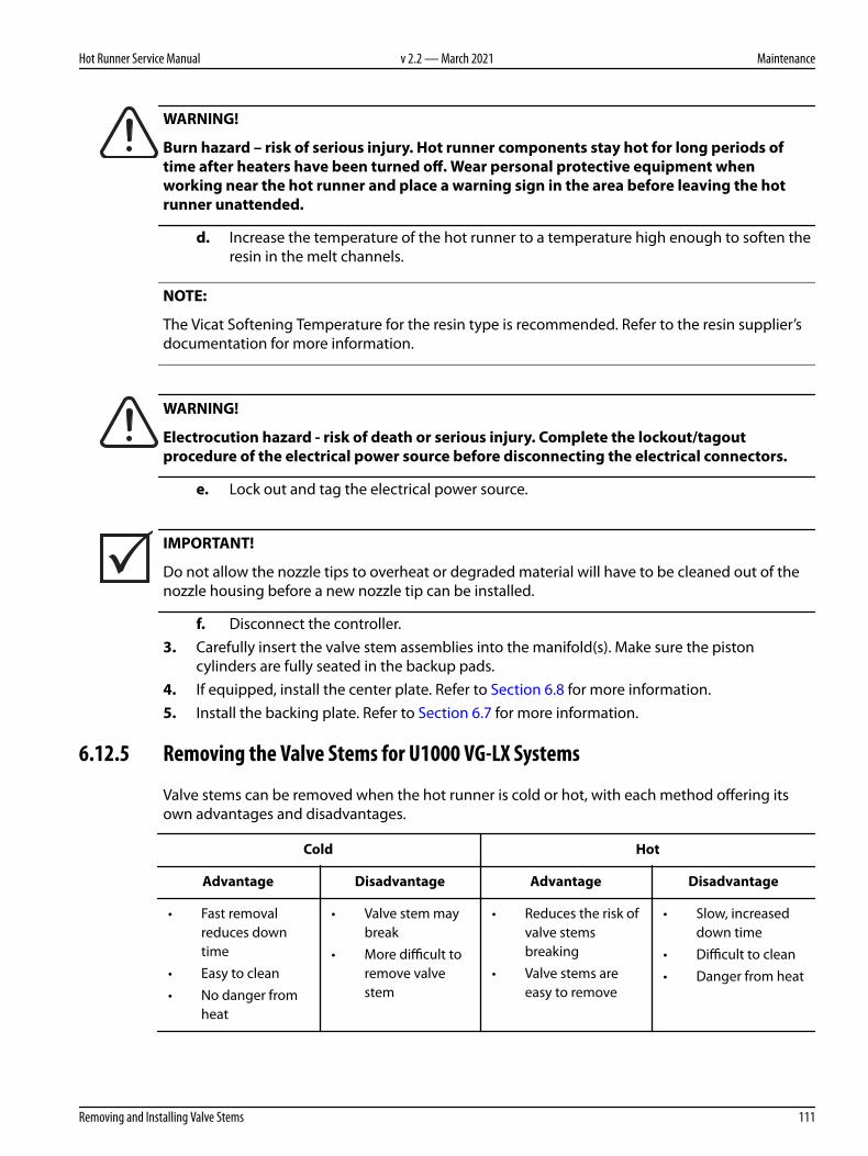
WARNING!
Burn hazard – risk of serious injury. Hot runner components stay hot for long periods oftime after heaters have been turned off. Wear personal protective equipment whenworking near the hot runner and place a warning sign in the area before leaving the hotrunner unattended.
d. Increase the temperature of the hot runner to a temperature high enough to soften theresin in the melt channels.
NOTE:
The Vicat Softening Temperature for the resin type is recommended. Refer to the resin supplier’sdocumentation for more information.
WARNING!
Electrocution hazard - risk of death or serious injury. Complete the lockout/tagoutprocedure of the electrical power source before disconnecting the electrical connectors.
e. Lock out and tag the electrical power source.
IMPORTANT!
Do not allow the nozzle tips to overheat or degraded material will have to be cleaned out of thenozzle housing before a new nozzle tip can be installed.
f. Disconnect the controller.3. Carefully insert the valve stem assemblies into the manifold(s). Make sure the piston
cylinders are fully seated in the backup pads.4. If equipped, install the center plate. Refer to Section 6.8 for more information.5. Install the backing plate. Refer to Section 6.7 for more information.
6.12.5 Removing the Valve Stems for U1000 VG-LX Systems
Valve stems can be removed when the hot runner is cold or hot, with each method offering itsown advantages and disadvantages.
Cold Hot
Advantage Disadvantage Advantage Disadvantage
• Fast removalreduces downtime
• Easy to clean• No danger from
heat
• Valve stem maybreak
• More difficult toremove valvestem
• Reduces the risk ofvalve stemsbreaking
• Valve stems areeasy to remove
• Slow, increaseddown time
• Difficult to clean• Danger from heat
Hot Runner Service Manual v 2.2 — March 2021 Maintenance
Removing and Installing Valve Stems 111

To remove valve stems from the hot runner, do the following:
NOTE:
This procedure can be performed in the machine or on a work bench.
1. Remove the backing plate. Refer to Section 6.7 for more information.2. If equipped, remove the center plate. Refer to Section 6.8 for more information.3. If the valve stems will be removed while the hot runner is cold, proceed to step 4. However, if
the valve stems will be removed while the hot runner is hot, do the following:a. Reconnect any thermocouples that were disconnected during disassembly.b. Connect the hot runner to a controller.c. Turn on the controller.
DANGER!
Electrocution hazard – risk of death, serious injury and/or damage to the hot runner. Do notturn on the heaters if water has leaked into the hot runner. If water has leaked into the hotrunner, the hot runner must be completely disassembled, dried and assembled before theheaters are turned on.
WARNING!
Hot resin spray hazard – risk of serious injury. Hot resin may unexpectedly spray from thenozzle tips while the hot runner is reaching operating temperature. To avoid serious burns,wear personal protective equipment consisting of a heat-resistant coat, heat-resistantgloves and a full face shield over safety glasses. Use adequate ventilation for fumes.
WARNING!
Burn hazard – risk of serious injury. Hot runner components stay hot for long periods oftime after heaters have been turned off. Wear personal protective equipment whenworking near the hot runner and place a warning sign in the area before leaving the hotrunner unattended.
d. Increase the temperature of the hot runner to a temperature high enough to soften theresin in the melt channels.
NOTE:
The Vicat Softening Temperature for the resin type is recommended. Refer to the resin supplier’sdocumentation for more information.
v 2.2 — March 2021 Ultra Valve Gate Hot Runner
112 Removing and Installing Valve Stems

WARNING!
Electrocution hazard - risk of death or serious injury. Complete the lockout/tagoutprocedure of the electrical power source before disconnecting the electrical connectors.
e. Lock out and tag the electrical power source.
IMPORTANT!
Do not allow the nozzle tips to overheat or degraded material will have to be cleaned out of thenozzle housing before a new nozzle tip can be installed.
f. Disconnect the controller.4. For each valve stem to be removed, do the following:
a. Remove the piston cylinder from the piston.
1
2
3
Figure 6-53: Piston Cylinder Assembly
1. Piston Cylinder 2. Piston 3. Backup Pad
b. From the valve stem removal tool assembly, connect the interface tool to the piston.
NOTE:
Refer to Section 1.8 for a list of special tools and part numbers.
Hot Runner Service Manual v 2.2 — March 2021 Maintenance
Removing and Installing Valve Stems 113

3
74
5
6
1
2
Figure 6-54: Valve Stem Removal Tool Assembly
1. Screw 2. Interface Tool 3. Piston and Valve Stem 4. Valve Stem Removal Tool 5. Valve Stem RemovalTool Base 6. Nut 7. Cap
c. Slide the valve stem removal tool base over the interface tool.d. Lower the sleeve and insert the cap beneath the thrust washers.e. Hold the valve stem removal tool in place and rotate the top nut clockwise until it is
tight.
CAUTION!
Mechanical hazard – risk of damage to the equipment. Be careful not to bend the valvestem when removing it. Bent valve stems cannot be re-used.
CAUTION!
Mechanical hazard – risk of damage to the equipment. If the valve stem and piston do notpull out easily, the valve stem may have seized in the manifold bushing. If this is the case,remove the manifold bushing from the manifold and remove the valve stem. Contact Huskyfor more information.
f. Using a wrench, rotate the nut on the valve stem removal tool clockwise to remove thevalve stem assembly.
NOTE:
Double delta seals must be replaced during the installation of the valve stem assemblies. Do notremove them at this time.
g. Remove the piston spacer and valve stem from the piston.
v 2.2 — March 2021 Ultra Valve Gate Hot Runner
114 Removing and Installing Valve Stems

4
2
1
3
Figure 6-55: Valve Stem Assembly
1. Piston 2. Double Delta Seal 3. Piston Spacer 4. Valve Stem
5. Inspect the gate end of the valve stems to make sure there is no damage or wear. If possible,use a new valve stem for comparison.
WARNING!
Burn, fire and gas hazard – risk of death or serious injury, and property damage. Use of anopen flame to remove resin can produce harmful gases (depending on the resin type),damage components and increase the risk of fire. Only use open flames sparingly and in acontrolled environment.
WARNING!
Burn hazard – risk of serious injury. To avoid serious burns, wear personal protectiveequipment consisting of a heat-resistant coat, heat-resistant gloves, and a full face shieldover safety glasses. Use adequate ventilation for fumes.
CAUTION!
Mechanical hazard – risk of damage to the equipment. Abrasives should never be used toclean the valve stems, as this could damage the critical sealing surfaces.
6. Remove any resin deposits from the valve stems. If required, carefully heat the resin depositswith a propane torch and then wipe the deposits away with a clean, soft cloth. This may haveto be repeated several times.
7. Make sure the valve stems are not overheated, scratched, scored, bent or worn. Replace eachvalve stem if it shows signs of this type of damage.
Hot Runner Service Manual v 2.2 — March 2021 Maintenance
Removing and Installing Valve Stems 115
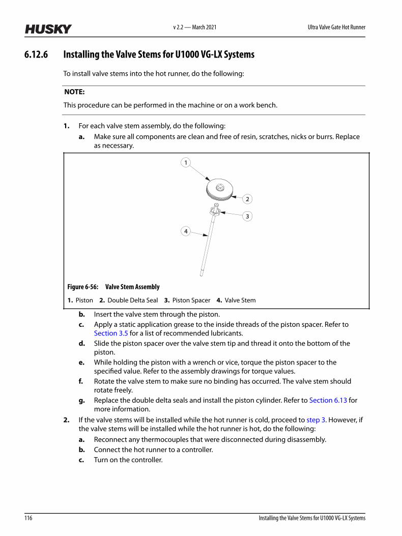
6.12.6 Installing the Valve Stems for U1000 VG-LX Systems
To install valve stems into the hot runner, do the following:
NOTE:
This procedure can be performed in the machine or on a work bench.
1. For each valve stem assembly, do the following:a. Make sure all components are clean and free of resin, scratches, nicks or burrs. Replace
as necessary.
4
2
1
3
Figure 6-56: Valve Stem Assembly
1. Piston 2. Double Delta Seal 3. Piston Spacer 4. Valve Stem
b. Insert the valve stem through the piston.c. Apply a static application grease to the inside threads of the piston spacer. Refer to
Section 3.5 for a list of recommended lubricants.d. Slide the piston spacer over the valve stem tip and thread it onto the bottom of the
piston.e. While holding the piston with a wrench or vice, torque the piston spacer to the
specified value. Refer to the assembly drawings for torque values.f. Rotate the valve stem to make sure no binding has occurred. The valve stem should
rotate freely.g. Replace the double delta seals and install the piston cylinder. Refer to Section 6.13 for
more information.2. If the valve stems will be installed while the hot runner is cold, proceed to step 3. However, if
the valve stems will be installed while the hot runner is hot, do the following:a. Reconnect any thermocouples that were disconnected during disassembly.b. Connect the hot runner to a controller.c. Turn on the controller.
v 2.2 — March 2021 Ultra Valve Gate Hot Runner
116 Installing the Valve Stems for U1000 VG-LX Systems

DANGER!
Electrocution hazard – risk of death, serious injury and/or damage to the hot runner. Do notturn on the heaters if water has leaked into the hot runner. If water has leaked into the hotrunner, the hot runner must be completely disassembled, dried and assembled before theheaters are turned on.
WARNING!
Hot resin spray hazard – risk of serious injury. Hot resin may unexpectedly spray from thenozzle tips while the hot runner is reaching operating temperature. To avoid serious burns,wear personal protective equipment consisting of a heat-resistant coat, heat-resistantgloves and a full face shield over safety glasses. Use adequate ventilation for fumes.
WARNING!
Burn hazard – risk of serious injury. Hot runner components stay hot for long periods oftime after heaters have been turned off. Wear personal protective equipment whenworking near the hot runner and place a warning sign in the area before leaving the hotrunner unattended.
d. Increase the temperature of the hot runner to a temperature high enough to soften theresin in the melt channels.
NOTE:
The Vicat Softening Temperature for the resin type is recommended. Refer to the resin supplier’sdocumentation for more information.
WARNING!
Electrocution hazard - risk of death or serious injury. Complete the lockout/tagoutprocedure of the electrical power source before disconnecting the electrical connectors.
e. Lock out and tag the electrical power source.
IMPORTANT!
Do not allow the nozzle tips to overheat or degraded material will have to be cleaned out of thenozzle housing before a new nozzle tip can be installed.
f. Disconnect the controller.3. Carefully insert the valve stem assemblies into the manifold(s). Make sure the piston
cylinders are fully seated in the backup pads.4. If equipped, install the center plate. Refer to Section 6.8 for more information.5. Install the backing plate. Refer to Section 6.7 for more information.
Hot Runner Service Manual v 2.2 — March 2021 Maintenance
Removing and Installing Valve Stems 117

6.13 Replacing the Double Delta Seals
To replace the double delta seals on the pistons, do the following:
1. Remove the backing plate. Refer to Section 6.7 for more information.2. If equipped, remove the center plate. Refer to Section 6.8.1 for more information.3. Remove the valve stem assemblies. Refer to Section 6.12 for more information.4. For each valve stem assembly that requires new double delta seals, do the following:
a. For VG-LX/EX hot runners only, remove, clean and inspect the piston cylinder. If thepiston cylinder is damaged, replace it immediately.
1 2
Figure 6-57: Piston Cylinder Inspection
1. Good Piston Cylinder 2. Damaged Piston Cylinder
CAUTION!
Mechanical hazard – risk of damage to the equipment. Do not damage the pistons whenremoving the seals. This will later diminish the integrity of the new seals.
b. Remove the outer and inner seals from the piston.
IMPORTANT!
Pistons must be cleaned before new seals are installed. Any debris or grease present will shortenthe service life of the seals.
c. Remove any loose debris or grease from the piston and surrounding area.d. Install the interior O-ring seal into the seal groove by rolling it over the piston. No tools
are required.
v 2.2 — March 2021 Ultra Valve Gate Hot Runner
118 Replacing the Double Delta Seals

2
1
Figure 6-58: Installing the Inner O-Ring Seal
1. Piston 2. Inner O-Ring Seal
e. Place the seal installation tool on top of the piston.
3
1
2
Figure 6-59: Installing the Outer O-Ring Seal
1. Seal Installation Tool 2. Outer O-Ring Seal 3. Piston
f. Install the outer O-ring seal by pushing the seal over the seal installation tool until it sitsover the interior O-ring seal.
g. Remove the seal installation tool.h. Slide the piston installation tool over the piston to compress the seals. This will protect
the seals from damage when the piston cylinder is installed.i. Inspect the piston assembly for damage, debris or grease.
NOTE:
The piston cylinder is easier to install when it is installed shortly after the piston installation tool isremoved.
j. For VG-LX/EX hot runners only, install the piston cylinder.5. Install the valve stem assemblies. Refer to Section 6.12 for more information.6. If equipped, install the center plate. Refer to Section 6.8.2 for more information.7. Install the backing plate. Refer to Section 6.7 for more information.
6.14 Removing and Installing Nozzle Tips
The following procedures describe how to remove and install nozzle tips.
Hot Runner Service Manual v 2.2 — March 2021 Maintenance
Replacing the Double Delta Seals 119

IMPORTANT!
The Ultra Helix Valve Gate nozzle heater must be removed to allow full engagement of the torquetool. The Husky supplied torque tool must be used to install the Ultra Helix nozzle tip or the tipmay be damaged.
NOTE:
On VG-HP systems, the nozzle tip and nozzle housing are one piece. Refer Section 6.16 to forinformation about removing the nozzle tip and housing.
NOTE:
When removing the nozzle tips, it is recommended they be removed when the hot runner is atroom temperature (< 25 °C or < 77 °F).
NOTE:
For U750 nozzle tips with U1000 VG-EXX RGA nozzles, refer to Section 6.14.3 for informationabout removing the nozzle tip and adapter, and Section 6.14.5 for information about installingthe nozzle tip and adapter.
6.14.1 Removing the Nozzle Tips when Hot
To remove the nozzle tips when they are hot, do the following:
NOTE:
The following procedure should only be performed when the nozzle tips cannot be removedwhen the hot runner is at room temperature (< 25 °C or < 77 °F).
1. Separate or remove the cavity plate from the hot runner. Refer to Section 6.6 for moreinformation.
2. Remove all nozzle heater components except for the nozzle heater and thermocouple. Referto Section 6.17 for more information.
3. If necessary, connect the hot runner to a controller.4. Remove all locks and tags. Refer to Section 2.5 for more information.5. Power up the machine or turn on the controller (if equipped).
DANGER!
Electrocution hazard – risk of death, serious injury and/or damage to the hot runner. Do notturn on the heaters if water has leaked into the hot runner. If water has leaked into the hotrunner, the hot runner must be completely disassembled, dried and assembled before theheaters are turned on.
v 2.2 — March 2021 Ultra Valve Gate Hot Runner
120 Removing the Nozzle Tips when Hot

WARNING!
Hot resin spray hazard – risk of serious injury. Hot resin may unexpectedly spray from thenozzle tips while the hot runner is reaching operating temperature. To avoid serious burns,wear personal protective equipment consisting of a heat-resistant coat, heat-resistantgloves and a full face shield over safety glasses. Use adequate ventilation for fumes.
WARNING!
Burn hazard – risk of serious injury. Hot runner components stay hot for long periods oftime after heaters have been turned off. Wear personal protective equipment whenworking near the hot runner and place a warning sign in the area before leaving the hotrunner unattended.
6. Increase the temperature of the nozzle housings to a temperature high enough to soften theresin around the nozzle tip threads. If there is no resin in the system, set the heat zones toroom temperature (<25 °C or <77 °F).
NOTE:
The Vicat Softening Temperature for the resin type is recommended. Refer to the resin supplier’sdocumentation for more information.
IMPORTANT!
Do not allow the nozzle tips to overheat or degraded material will have to be cleaned out of thenozzle housing before a new nozzle tip can be installed.
7. Lock out and tag the machine and controller (if equipped).
WARNING!
Burn hazard – risk of serious injury. To avoid serious burns, wear personal protectiveequipment consisting of a heat-resistant coat, heat-resistant gloves, and a full face shieldover safety glasses. Use adequate ventilation for fumes.
CAUTION!
Mechanical hazard – risk of damage to the equipment. Support nozzle tip sockets squarelyover the nozzle tips to prevent side-load on the tip.
8. Using an appropriate nozzle tip socket, loosen each nozzle tip that will be removed. Do notunscrew or remove the nozzle tips.
Refer to Section 1.8 for a list of available nozzle tip sockets.
Hot Runner Service Manual v 2.2 — March 2021 Maintenance
Removing and Installing Nozzle Tips 121

WARNING!
Burn hazard – risk of serious injury. To avoid serious burns, wear personal protectiveequipment consisting of a heat-resistant coat, heat-resistant gloves and a full face shieldover safety glasses. Use adequate ventilation for fumes.
9. Wearing appropriate personal protective equipment, hand tighten each nozzle tip while theresin is still soft until the nozzle tips touch the nozzle housing.
10. Allow the nozzle tips to cool to room temperature (< 25 °C or < 77 °F). This may take 1/2 to 4hours depending on the size of the hot runner. However, this step will reduce the risk of resinsolidifying on the nozzle tip sealing surfaces.
11. Remove the nozzle tips using the nozzle tip socket.
1
2
3
Figure 6-60: Removing a Nozzle Tip
1. Nozzle Tip 2. Valve Stem 3. Nozzle Housing
12. Remove the nozzle heaters. Refer to Section 6.17 for more information.
IMPORTANT!
Care must be taken to prevent damage to the nozzle tip and nozzle sealing surfaces.
13. Remove any resin from the interior of the nozzle tip using a soft wire brush or equivalent.14. Remove any resin from the interior and exterior of the nozzle housing using a soft wire brush
or equivalent.
NOTE:
Do not remove locks and tags until the nozzle tips are installed.
6.14.2 Removing the Nozzle Tips when Cold
To remove the nozzle tips when they are cold, do the following:
1. Separate or remove the cavity plate from the hot runner. Refer to Section 6.6 for moreinformation.
v 2.2 — March 2021 Ultra Valve Gate Hot Runner
122 Removing the Nozzle Tips when Cold

2. Remove all nozzle heater components except for the nozzle heater and thermocouple. Referto Section 6.17 for more information.
CAUTION!
Mechanical hazard – risk of damage to the hot runner. Solidified resin can make it difficultto loosen the nozzle tips. Too much force when loosening the nozzle tips could damage thesealing surfaces.
If the nozzle tips do not loosen easily, heat up the nozzle tips before removing them. Referto Section 6.14.1 for more information.
3. Using an appropriate nozzle tip socket, loosen each nozzle tip that will be removed. Do notunscrew or remove the nozzle tips.
Refer to Section 1.8. for a list of available nozzle tip sockets.4. Remove the nozzle tips using the nozzle tip socket.
1
2
3
Figure 6-61: Removing a Nozzle Tip
1. Nozzle Tip 2. Valve Stem 3. Nozzle Housing
5. Remove the nozzle heaters. Refer to Section 6.17 for more information.
IMPORTANT!
Care must be taken to prevent damage to the nozzle tip and nozzle sealing surfaces.
6. Remove any resin from the interior of the nozzle tip using a soft wire brush or equivalent.7. Remove any resin from the interior and exterior of the nozzle housing using a soft wire brush
or equivalent.
NOTE:
Do not remove locks and tags until the nozzle tips are installed.
Hot Runner Service Manual v 2.2 — March 2021 Maintenance
Removing and Installing Nozzle Tips 123

6.14.3 Removing U750 Nozzle Tips with U1000 VG-EXX RGA Nozzles
The following procedure describes how to remove U750 nozzle tips with U1000 VG-EXX RGAnozzles.
NOTE:
Nozzle tips must be removed first, followed by the nozzle tip adapters. Whenever the nozzle tip isremoved, the nozzle tip must also be removed so that the correct torque is applied when re-installed.
To remove the nozzle tips when they are hot, refer to section Section 6.14.1.
To remove the nozzle tips when they are cold, refer to section Section 6.14.2.
To remove the nozzle tip adapter, do the following:
1. Using an appropriate socket, loosen each nozzle tip adapter that will be removed. Refer to Section 1.8 for a list of available sockets.
WARNING!
Burn hazard - risk of serious injury. To avoid serious burns, wear personal protectiveequipment consisting of a heat-resistant coat, heat-resistant gloves and a full face shieldover safety glasses. Use adequate ventilation for fumes.
2. Wearing appropriate personal protective equipment, hand tighten each nozzle tip adapterwhile the resin is soft until the nozzle tip adapter touches the nozzle housing.
2 3 4 5
1
Figure 6-62: U1000 VG-EXX RGA Nozzle
1. U750 Shim 2. U750 Nozzle Tip 3. Nozzle Tip Adapter 4. Valve Stem 5. U1000 Nozzle Housing
3. Allow the nozzle tip adapters to cool to room temperature ( < 25 °C (< 77 °F) ) . This may take1/2 to 4 hours depending on the size of the hot runner. However, this step will reduce therisk of resin solidifying on the nozzle tip sealing surfaces.
4. Remove the nozzle tip adapter using a socket or open-end wrench.
v 2.2 — March 2021 Ultra Valve Gate Hot Runner
124 Removing U750 Nozzle Tips with U1000 VG-EXX RGA Nozzles

6.14.4 Installing the Nozzle Tips
To install a nozzle tip, do the following:
IMPORTANT!
Ultra Helix Valve Gate nozzle tips need to be installed after the valve stems are installed to reducethe risk of stem damage in cold condition, especially with drop locations farther away from thecenter of expansion. UltraHelix is especially susceptible to damage due to the smaller diameter ofthe Helix guiding feature.
IMPORTANT!
Make sure the Ultra Helix valve stem is installed in the closed position before fastening the nozzletip to the nozzle housing body. This prevents the valve stem from binding in the spiraled portionof the Ultra Helix nozzle tips.
IMPORTANT!
The Ultra Helix Valve Gate nozzle heater must be removed to allow full engagement of the torquetool. The Husky supplied torque tool must be used to install the Ultra Helix nozzle tip or the tipmay be damaged.
NOTE:
Nozzle tips must be installed when the resin and nozzle housings are cold.
1. Lock out and tag the machine and controller (if equipped). Refer to Section 2.5 for moreinformation.
IMPORTANT!
If resin or other residues are not thoroughly cleaned off the threads and seating areas of both thenozzle tip and nozzle housing, the result could lead to the following:
• Compressive overload of the tip, even at the correct torque recommendation, causingdamage to the tip (permanently shortened)
• A tip which is no longer tight after it has been heated up and cooled down• Poor performance or quality of the gate due to the incorrect tip position (too far back or too
far forward)• Leakage between the nozzle tip and nozzle tip insulator, permitting the formation of
degraded resin• Thread stripping
2. Remove any resin or other residue found on the nozzle tips and nozzle housings.
Hot Runner Service Manual v 2.2 — March 2021 Maintenance
Removing and Installing Nozzle Tips 125

3. If the nozzle housing has an external thread, proceed to step 4. Otherwise, clean the nozzletip seating surface at the bottom of the nozzle housing bore with a soft wire brush.
4. Make sure the nozzle tip and nozzle housing are clean and dry.5. For Ultra Helix Valve Gate, make sure the valve stem is fully forward in the closed position.
The valve stem should slide smoothly into the stem guide. If there is any resistance, theguide is not properly engaged and the tip should be re-positioned or the valve stem will bedamaged.
6. Using a nozzle tip socket, install the nozzle tip and torque it to the value printed on thenozzle tip. Refer to Section 1.8 for a list of available nozzle tip sockets.
1
2
3
Figure 6-63: Installing a Nozzle Tip
1. Nozzle Tip 2. Valve Stem 3. Nozzle Housing
7. Install the nozzle heater. Refer to Section 6.17 for more information.8. Measure the height of the nozzle tip using a depth micrometer and compare the
measurement to the tip height listed on the Tip Chart in the assembly drawings.
If the nozzle tip height is outside the tolerances listed on the Tip Chart, refer to Section 6.14.6.
Figure 6-64: Measuring the Nozzle Tip Height
9. Remove all locks and tags.10. Install the cavity plate. Refer to Section 6.6 for more information.
v 2.2 — March 2021 Ultra Valve Gate Hot Runner
126 Removing and Installing Nozzle Tips

6.14.5 Installing U750 Nozzle Tips with U1000 VG-EXX RGA Nozzles
The following procedure describes how to install U750 nozzle tips with U1000 VG-EXX RGAnozzles.
NOTE:
Install and torque the nozzle tip adapter first, then install and torque the nozzle tip. Do not installand torque them as a single unit.
2 3 4 5
1
Figure 6-65: U1000 VG-EXX RGA Nozzle
1. U750 Shim 2. U750 Nozzle Tip 3. Nozzle Tip Adapter 4. Valve Stem 5. U1000 Nozzle Housing
To install the nozzle tip adapter, do the following:
IMPORTANT!
Ultra Helix Valve Gate nozzle tips need to be installed after the valve stems are installed to reducethe risk of stem damage in cold condition, especially with drop locations farther away from thecenter of expansion. Ultra Helix is especially susceptible to damage due to the smaller diameter ofthe Helix guiding feature.
IMPORTANT!
Make sure the Ultra Helix valve stem is installed in the closed position before fastening the nozzletip to the nozzle housing body. This prevents the valve stem from binding in the spiraled portionof the Ultra Helix nozzle tips.
NOTE:
Nozzle tips must be installed when the resin and nozzle housings are cold.
Hot Runner Service Manual v 2.2 — March 2021 Maintenance
Removing and Installing Nozzle Tips 127

1. Lock out and tag the machine and controller (if equipped). Refer to Section 2.5 for moreinformation.
IMPORTANT!
If resin or other residue are not thoroughly cleaned off the threads and seating area of both thenozzle tip adapter and nozzle housing, the result could lead to the following:
• Compressive overload of the tip, even at the correct torque recommendation, causingdamage to the tip (permanently shortened)
• A tip which is no longer tight after it has been heated up and cooled down• Poor performance or quality of the gate due to the incorrect tip position (too far back or too
far forward)• Leakage between the nozzle tip, nozzle tip adapter, and nozzle tip insulator, permitting the
formation of degraded resin• Thread stripping
2. Remove any resin or other residue found on the nozzle tip, nozzle tip adapters, and nozzlehousings.
3. If the nozzle housing has an external thread, proceed to step 4. Otherwise, clean the nozzletip adapter seating surface at the bottom of the nozzle housing bore with a soft wire brush.
4. Make sure the nozzle tip adapter and nozzle housings are clean and dry.5. For Ultra Helix Valve Gate, make sure the valve stem is fully forward in the closed position.
The valve stem should slide smoothly into the stem guide. If there is any resistance, theguide is not properly engaged and the tip should be re-positioned or the valve stem will bedamaged.
6. Using an appropriate socket, install the nozzle tip adapter and torque it to the value printedon the adapter. Refer to Section 1.8 for a list of available sockets.
To install the nozzle tips refer to Section 6.14.4.
6.14.6 Troubleshooting Nozzle Tip Heights
The following describes reasons and corrective action for nozzle heights that are less or morethan the values listed on the Tip Chart.
Problem Reason Action
Dimension is shorterthan required tipheight
Nozzle tip has been over-tightened, worn, or damaged
1. Remove the nozzle tip2. Clean resin from the nozzle tip and
nozzle housing3. Replace or install new nozzle tip
v 2.2 — March 2021 Ultra Valve Gate Hot Runner
128 Troubleshooting Nozzle Tip Heights

Problem Reason Action
Dimension is longerthan required tipheight
Nozzle tip is damagedORNozzle tip is being preventedfrom seating in the nozzlehousing by resin under thenozzle tip seating surface.
1. Remove the nozzle tip2. Clean resin from the nozzle tip and
nozzle housing3. Re-apply the torque to the nozzle tip4. Verify the nozzle tip height
6.15 Refurbishing Ultra Flow VG Nozzle Tips
To refurbish Ultra Flow VG nozzle tips, do the following:
1. Remove the nozzle tips from the nozzle assembly.2. Thermally clean the tips by burning out the plastic (pyrolysis). Heat them at 400 °C (752 °F)
for 60 minutes. Do not exceed 450 °C (842 °F) .
NOTE:
For best results, use an oven capable of heating the tips under a vacuum.
3. Allow the tips to cool, then clean the ash from the them using a small soft wire brush.4. Allow the tips to cool, then clean the ash from the them using a small soft wire brush.5. Visually inspect the internal surface of each tip for remaining plastic or ash.
NOTE:
A boroscope, if available, is best for this visual inspection.
6. Repeat steps 2 to 5 if any plastic remains in the tip.7. Inspect each tip for burrs or damage.8. Install the nozzle tips into the nozzle assembly.
NOTE:
If the tips are to be stored, coat them inside and out with anti-rust oil.
6.16 Removing and Installing Nozzle Housings
The following procedures describe how to remove, maintain and install nozzle housings.
Hot Runner Service Manual v 2.2 — March 2021 Maintenance
Removing and Installing Nozzle Tips 129

6.16.1 Removing VG-LX and EX and SX Nozzle Housings
To remove a nozzle housing, do the following:
1. Remove the hot runner from the machine. Refer to Section 4.3.2 for more information.2. Remove the cavity plate. Refer to Section 6.6 for more information.3. Remove the nozzle tip. Refer to Section 6.14.1 for more information.4. Remove the nozzle heaters and thermocouples. Refer to Section 6.17 for more information.5. Remove the backing plate. Refer to Section 6.7 for more information.6. If equipped, remove the center plate. Refer to Section 6.8.1 for more information.7. Remove the manifolds and cross manifold (if equipped). Refer to Section 6.9 for more
information.
CAUTION!
Mechanical hazard – risk of damage to the hot runner. Use a brass rod to protect themanifold plate and nozzle from damage.
8. Break the resin around the nozzle housing with a side impact against the nozzle flange at themanifold face.
9. Pull the nozzle stack assembly out of the manifold pocket and disassemble.
Figure 6-66: Nozzle Stack Assembly
1. Retaining Clip 2. Nozzle Locating Insulator 3. Ultra Springs 4. Anti-Rotation Tab 5. NozzleHousing
10. Inspect and clean the nozzle housing. Refer to Section 6.16.5 for more information.
6.16.2 Installing VG-LX and EX and SX Nozzle Housings
To install the nozzle housings, do the following:
1. Assemble each nozzle housing.
v 2.2 — March 2021 Ultra Valve Gate Hot Runner
130 Removing VG-LX and EX and SX Nozzle Housings

NOTE:
Refer to the assembly drawings to verify the orientation and correct number of Ultra springs.
1
2
34
5
6
Figure 6-67: Nozzle Stack Assembly and Installation
1. Retaining Clip 2. Nozzle Locating Insulator 3. Ultra Springs 4. Anti-Rotation Tab 5. NozzleHousing 6. Nozzle Bore
2. Place all housing assemblies into the nozzle bores in the manifold plate. Make sure thehousing assemblies are properly aligned with the nozzle locating dowels to prevent rotation.
3. Install the manifolds and cross manifold (if equipped). Refer to Section 6.9 for moreinformation.
4. If equipped, install the center plate. Refer to Section 6.8.2 for more information.5. Install the backing plate. Refer to Section 6.7 for more information.6. Install the nozzle heaters and thermocouples. Refer to Section 6.17 for more information.7. Install the nozzle tip. Refer to Section 6.14.4 for more information.8. Install the cavity plate. Refer to Section 6.6 for more information.9. Install the hot runner into the machine. Refer to Section 4.3 for more information.
6.16.3 Removing VG-HP and VX-HP Nozzle Housings
To remove a nozzle housing, do the following:
1. Remove the hot runner from the machine. Refer to Section 4.3.2 for more information.2. Remove the cavity plate. Refer to Section 6.6 for more information.3. Remove the nozzle tip. Refer to Section 6.14.1 for more information.4. Remove the nozzle heaters and thermocouples. Refer to Section 6.17 for more information.5. Remove the backing plate. Refer to Section 6.7 for more information.6. If equipped, remove the center plate. Refer to Section 6.8.1 for more information.7. Remove the manifolds and cross manifold (if equipped). Refer to Section 6.9 for more
information.
Hot Runner Service Manual v 2.2 — March 2021 Maintenance
Removing and Installing Nozzle Housings 131
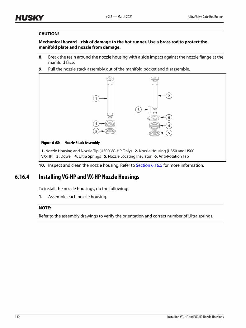
CAUTION!
Mechanical hazard – risk of damage to the hot runner. Use a brass rod to protect themanifold plate and nozzle from damage.
8. Break the resin around the nozzle housing with a side impact against the nozzle flange at themanifold face.
9. Pull the nozzle stack assembly out of the manifold pocket and disassemble.
4
5
1
6
4
5
3
2
Figure 6-68: Nozzle Stack Assembly
1. Nozzle Housing and Nozzle Tip (U500 VG-HP Only) 2. Nozzle Housing (U350 and U500VX‑HP) 3. Dowel 4. Ultra Springs 5. Nozzle Locating Insulator 6. Anti-Rotation Tab
10. Inspect and clean the nozzle housing. Refer to Section 6.16.5 for more information.
6.16.4 Installing VG-HP and VX-HP Nozzle Housings
To install the nozzle housings, do the following:
1. Assemble each nozzle housing.
NOTE:
Refer to the assembly drawings to verify the orientation and correct number of Ultra springs.
v 2.2 — March 2021 Ultra Valve Gate Hot Runner
132 Installing VG-HP and VX-HP Nozzle Housings

4
5
1
6
4
5
3
2
Figure 6-69: Nozzle Stack Assembly
1. Nozzle Housing and Nozzle Tip (U500 VG-HP Only) 2. Nozzle Housing (U350 and U500VX‑HP) 3. Dowel 4. Ultra Springs 5. Nozzle Locating Insulator 6. Anti-Rotation Tab
2. Place all housing assemblies into the nozzle bores in the manifold plate. Make sure thehousing assemblies are properly aligned with the nozzle locating dowels to prevent rotation.
3. Install the manifolds and cross manifold (if equipped). Refer to Section 6.9 for moreinformation.
4. If equipped, install the center plate. Refer to Section 6.8.2 for more information.5. Install the backing plate. Refer to Section 6.7.2 for more information.6. Install the nozzle tip. Refer to Section 6.14.4 for more information.7. Install the nozzle heaters and thermocouples. Refer to Section 6.17 for more information.8. Install the cavity plate. Refer to Section 6.6 for more information.
6.16.5 Inspecting and Cleaning Nozzle Housings
To inspect and clean the nozzle housings after they have been removed, do the following:
CAUTION!
Mechanical hazard – risk of equipment damage. Do not hone the back surface of the nozzlehousing to remove nicks and burrs. The back surface is a precision made section of thehousing with a contoured surface. Honing this section will cause the system to leak andvoid the leak proof guarantee for the hot runner.
1. Inspect all nozzle stack components for damage or wear. Replace as necessary.2. If the nozzle housing has an internal thread, clean the nozzle tip seating surface at the
bottom of the nozzle housing bore. This step is not required for nozzle housings that have anexternal thread.
3. Clean the thread with a soft wire brush.4. Remove all resin from the melt channel in the nozzle housing.5. Remove all resin from the nozzle housing bore in the manifold plate.
Hot Runner Service Manual v 2.2 — March 2021 Maintenance
Removing and Installing Nozzle Housings 133

6.17 Removing and Installing Nozzle Heaters
The following procedures describe how to remove and install nozzle heaters. The following typesof nozzle heaters are supported:
IMPORTANT!
Husky nozzle heaters are rugged and have a long service life. Only replace nozzle heaters withHusky approved parts. Use of components not sold or approved by Husky will void the hot runnerwarranty.
• HTM heaters for U350, U500 and U750 systems• HTM heaters for U1000 systems• Copper heaters for U500 systems• Ultra Nozzle Heaters (UNH) with front rings for U500 and U750 systems• Ultra Nozzle Heaters (UNH) with ring thermocouples for U500 and U750 systems• Bi-metal heaters for U500, U750 and U1000 systems• VG-HP heaters for U500 systems
6.17.1 Removing and Installing HTM Nozzle Heaters for U350, U500 and U750Systems
The following procedures describe how to remove and install HTM nozzle heaters for U350, U500and U750 systems.
6.17.1.1 Removing HTM Nozzle Heaters for U350, U500 and U750 Systems
To remove an HTM nozzle heater, do the following:
1. Separate or remove the cavity plate from the hot runner. Refer to Section 6.6 for moreinformation.
2. Remove the retaining clip from the nozzle tip.
v 2.2 — March 2021 Ultra Valve Gate Hot Runner
134 Removing and Installing Nozzle Heaters

7
1 2
3
4
5
6
Figure 6-70: HTM Nozzle Heater Assembly
1. HTM Heater with Set Screw 2. HTM Heater without Set Screw 3. Retaining Clip 4. HTM NozzleHeater 5. Nozzle Tip 6. Wave Springs 7. Set Screw
3. Remove the necessary wire clips to expose the nozzle heater and thermocouple wires.
NOTE:
The nozzle heater assembly includes the retaining sleeve, nozzle heater and thermocouple.
4. Remove retaining set screw on the heater sleeve, if applicable.5. Remove the nozzle heater assembly.6. Remove and discard the wave springs.
6.17.1.2 Installing HTM Nozzle Heaters for U350, U500 and U750 Systems
To install an HTM nozzle heater for U350, U500 and U750 systems, do the following:
1. Install new wave springs over the nozzle housing and nozzle tip.
Hot Runner Service Manual v 2.2 — March 2021 Maintenance
Removing and Installing Nozzle Heaters 135

7
1 2
3
4
5
6
Figure 6-71: HTM Nozzle Heater Assembly
1. HTM Heater with Set Screw 2. HTM Heater without Set Screw 3. Retaining Clip 4. HTM NozzleHeater 5. Nozzle Tip 6. Wave Springs 7. Set Screw
2. Slide the nozzle heater assembly over the nozzle housing far enough to show the retainingclip groove on the nozzle tip.
3. Install the retaining clip on the nozzle tip and pull the nozzle heater assembly up against it.4. Install the set screw, if applicable.5. Route the nozzle heater and thermocouple wires through the wire channels in the manifold
plate. Make sure all wiring is properly retained in the wire channels using wire clips.6. Make sure to stagger the knuckles in the wire grooves.
Figure 6-72: Staggering the Knuckles in the Wire Grooves
NOTE:
All wire, including heater or thermocouple wire, that could contact a heated component such as anozzle housing or manifold must be mineral insulated high temperature wire (hard lead). If themineral insulated lead is not long enough to allow this, additional steps must be taken, such asusing high temperature sleeving, to prevent the knuckles and PTFE or Kapton insulated wire (softlead) from overheating.
7. Label each wire with the heater zone number. Refer to the electrical schematic for the zonenumber.
8. Crimp the wire ends and connect the wires to the appropriate multi-pin connectors. Refer tothe electrical schematic for more information.
9. Test each nozzle heater. Refer to Section 6.5 for more information.10. Install the cavity plate. Refer to Section 6.6 for more information.
v 2.2 — March 2021 Ultra Valve Gate Hot Runner
136 Removing and Installing Nozzle Heaters

6.17.2 Removing and Installing HTM Nozzle Heaters for U1000 Systems
The following procedures describe how to remove and install HTM nozzle heaters for U1000systems.
6.17.2.1 Removing HTM Nozzle Heaters for U1000 Systems
To remove the HTM nozzle heaters for a U1000 system, do the following:
1. Separate or remove the cavity plate from the hot runner. Refer to Section 6.6 for moreinformation.
2. Remove the retaining clip from the nozzle tip.
1
2
3
4
5
6
7
Figure 6-73: HTM Nozzle Heater Assembly
1. Retaining Clip 2. Thermocouple Retaining Clip 3. Thermocouple 4. HTM Heater 5. RetainingSleeve 6. Nozzle Tip 7. Wave Spring
3. Remove the retaining sleeve, if applicable.4. Remove the necessary wire clips to expose the nozzle heater and thermocouple wires.
NOTE:
The nozzle heater assembly includes the retaining sleeve, nozzle heater and thermocouple.
5. Remove the thermocouple retaining clip from the nozzle heater.6. Disconnect the thermocouple from the nozzle heater.7. Remove the nozzle heater and thermocouple.8. Remove and discard the wave springs.
6.17.2.2 Installing HTM Nozzle Heaters for U1000 Systems
To install an HTM heater for a U1000 system, do the following:
1. Install new wave springs over the nozzle housing and nozzle tip.
Hot Runner Service Manual v 2.2 — March 2021 Maintenance
Removing and Installing Nozzle Heaters 137

1
2
3
4
5
6
7
Figure 6-74: HTM Nozzle Heater Assembly
1. Retaining Clip 2. Thermocouple Retaining Clip 3. Thermocouple 4. HTM Heater 5. Retaining Sleeve 6. Nozzle Tip 7. Wave Spring
2. Slide the nozzle heater assembly over the nozzle housing.3. Insert the tip of the thermocouple with a downward motion into one of the thermocouple
probe holes.
IMPORTANT!
Make sure that the tip of the thermocouple is pressed all the way down into the hole in the heaterbody. This will help to secure the thermocouple effectively.
1
Figure 6-75: Thermocouple "U" Bend
1. Thermocouple
4. Install the thermocouple retaining clip on the nozzle heater.5. Install the retaining clip on the nozzle tip.6. Bend the thermocouple so it is tight to the heater body (the end of the thermocouple should
now be bent in a U-shape).
v 2.2 — March 2021 Ultra Valve Gate Hot Runner
138 Removing and Installing Nozzle Heaters

7. Install the retaining sleeve over the nozzle heater and thermocouple, if applicable.8. Route the nozzle heater and thermocouple wires through the wire channels in the manifold
plate. Make sure all wiring is properly retained in the wire channels using wire clips.9. Pull the heater away from the retaining clip and release it. Make sure the heater moves back
into place and contacts the retaining clip.10. Make sure to stagger the knuckles in the wire grooves.
Figure 6-76: Staggering the Knuckles in the Wire Grooves
NOTE:
All wire, including heater or thermocouple wire, that could contact a heated component such as anozzle housing or manifold must be mineral insulated high temperature wire (hard lead). If themineral insulated lead is not long enough to allow this, additional steps must be taken, such asusing high temperature sleeving, to prevent the knuckles and PTFE or Kapton insulated wire (softlead) from overheating.
11. Label each wire with the heater zone number. Refer to the electrical schematic for the zonenumber.
12. Crimp the wire ends and connect the wires to the appropriate multi-pin connectors. Refer tothe electrical schematic for more information.
13. Test each nozzle heater. Refer to Section 6.5 for more information.14. Install the cavity plate. Refer to Section 6.6 for more information.
6.17.3 Removing and Installing Copper Nozzle Heaters
The following procedures describe how to remove and install copper nozzle heaters.
6.17.3.1 Removing Copper Nozzle Heaters
To remove a copper nozzle heater, do the following:
1. Separate or remove the cavity plate from the hot runner. Refer to Section 6.6 for moreinformation.
2. Remove the front ring.
Hot Runner Service Manual v 2.2 — March 2021 Maintenance
Removing and Installing Nozzle Heaters 139

1
5
2
3
4
6
Figure 6-77: Copper Nozzle Heater Assembly
1. Front Ring 2. Retaining Sleeve (If Equipped) 3. Retaining Clip 4. CopperHeater 5. Thermocouple 6. Nozzle Tip
3. If equipped, remove the retaining sleeve.4. Disconnect the thermocouple from the nozzle heater.5. Remove the retaining clip from the nozzle tip.6. Remove the necessary wire clips to expose the nozzle heater and thermocouple wires.7. Remove the nozzle heater and thermocouple.
6.17.3.2 Installing Copper Nozzle Heaters
To install a copper nozzle heater, do the following:
1. Slide the nozzle heater over the nozzle housing and nozzle tip.
1
5
2
3
4
6
Figure 6-78: Copper Nozzle Heater Assembly
1. Front Ring 2. Retaining Sleeve (If Equipped) 3. Retaining Clip 4. CopperHeater 5. Thermocouple 6. Nozzle Tip
2. Install the retaining clip around the nozzle tip.3. Connect the thermocouple to the nozzle heater.4. Pull the nozzle heater up against the retaining clip.5. If equipped, install the retaining sleeve over the nozzle heater and thermocouple.
v 2.2 — March 2021 Ultra Valve Gate Hot Runner
140 Installing Copper Nozzle Heaters

6. Install the front ring and tighten by hand.7. Route the nozzle heater and thermocouple wires through the wire grooves in the manifold
plate. Make sure all wiring is properly retained in the wire grooves using wire clips.8. Make sure to stagger the knuckles in the wire grooves.
Figure 6-79: Staggering the Knuckles in the Wire Grooves
NOTE:
All wiring along the nozzle heater must be either a high temperature braid or sleeved using ahigh temperature sleeving.
9. Label each wire with the heater zone number. Refer to the electrical schematic for the zonenumber.
10. Crimp the wire ends and connect the wires to the appropriate multi-pin connectors. Refer tothe electrical schematic for more information.
11. Test each nozzle heater zone. Refer to Section 6.5 for more information.
6.17.4 Removing and Installing Ultra Nozzle Heaters With Front Rings (UNH 500 and750)
The following procedures describe how in remove and install ultra nozzle heaters with front rings.
6.17.4.1 Removing Ultra Nozzle Heaters (UNH) With Front Rings
To replace an Ultra Nozzle Heater (UNH) with a front ring, do the following:
1. Separate or remove the cavity plate from the hot runner. Refer to Section 6.6 for moreinformation.
2. Remove the front ring.
Hot Runner Service Manual v 2.2 — March 2021 Maintenance
Removing and Installing Nozzle Heaters 141

1
34
2
5
Figure 6-80: Ultra Nozzle Heater (UNH) Assembly With Front Rings
1. Front Ring 2. Retaining Clip 3. Ultra Nozzle Heater (UNH) 4. Thermocouple 5. Nozzle Tip
3. Disconnect the thermocouple from the nozzle heater.4. Remove the retaining clip from the nozzle tip.5. Remove the necessary wire clips to expose the nozzle heater and thermocouple wires.6. Remove the nozzle heater and thermocouple.
6.17.4.2 Installing Ultra Nozzle Heaters (UNH) with Front Rings
To install an Ultra Nozzle Heater (UNH) with a front ring, do the following:
1. Slide the nozzle heater over the nozzle housing and nozzle tip.
1
34
2
5
Figure 6-81: Ultra Nozzle Heater (UNH) Assembly with a Front Ring
1. Front Ring 2. Retaining Clip 3. Ultra Nozzle Heater (UNH) 4. Thermocouple 5. Nozzle Tip
2. Install the retaining clip around the nozzle tip.3. Connect the thermocouple to the nozzle heater.4. Pull the nozzle heater up against the retaining clip.5. Install the front ring and tighten by hand.
v 2.2 — March 2021 Ultra Valve Gate Hot Runner
142 Installing Ultra Nozzle Heaters (UNH) with Front Rings

CAUTION!
Mechanical hazard – risk of damage to the hot runner. Do not bend the nozzle heater wiresat a 90° angle. Do not bend the nozzle heater wires directly at the lead exit of the heaterbody. The wires will crack or break over time.
6. On the U750 heaters, bend the nozzle heater wires in an arc against the heater body. Makesure each bend has a minimum 10 mm (0.4 in) radius.
1
2
Figure 6-82: Ultra Nozzle Heater - U750
1. Ultra Nozzle Heater 2. Nozzle Heater Wires
7. On U500 heaters, first bend the leads along the curvature of the heater, and then bend themup or down (away from the lead exit of the heater body) to meet the manifold plate wiregroove as required.
1 2
Figure 6-83: Ultra Nozzle Heater - U500
1. Heater leads before bending 2. Heater leads after bending
8. Route the nozzle heater and thermocouple wires through the wire channels in the manifoldplate. Make sure all wiring is properly retained in the wire channels using wire clips.
9. Make sure to stagger the knuckles in the wire grooves.
Hot Runner Service Manual v 2.2 — March 2021 Maintenance
Removing and Installing Nozzle Heaters 143

Figure 6-84: Staggering the Knuckles in the Wire Grooves
NOTE:
All wire, including heater or thermocouple wire, that could contact a heated component such as anozzle housing or manifold must be mineral insulated high temperature wire (hard lead). If themineral insulated lead is not long enough to allow this, additional steps must be taken, such asusing high temperature sleeving, to prevent the knuckles and PTFE or Kapton insulated wire (softlead) from overheating.
10. Label each wire with the heater zone number. Refer to the electrical schematic for the zonenumber.
11. Crimp the wire ends and connect the wires to the appropriate multi-pin connectors. Refer tothe electrical schematic for more information.
12. Test each nozzle heater. Refer to Section 6.5 for more information.
6.17.5 Removing and Installing Ultra Nozzle Heaters (UNH) With Ring Thermocouples
The following procedures describe how to remove and install ultra nozzle heaters with ringthermocouples (UNH 500 and UNH 750).
6.17.5.1 Removing Ultra Nozzle Heaters (UNH) With Ring Thermocouples
To replace an Ultra Nozzle Heater (UNH) with a ring thermocouple, do the following:
1. Separate or remove the cavity plate from the hot runner. Refer to Section 6.6 for moreinformation.
2. Remove the retaining clip from the nozzle tip.3. Remove the necessary wire clips to expose the nozzle heater and thermocouple wires.4. Remove the ring thermocouple.
v 2.2 — March 2021 Ultra Valve Gate Hot Runner
144 Removing and Installing Ultra Nozzle Heaters (UNH) With Ring Thermocouples

1
2
3
4
5
Figure 6-85: Ultra Nozzle Heater (UNH) Assembly With a Ring Thermocouple
1. Retaining Clip 2. Ring Thermocouple 3. Ultra Nozzle Heater (UNH) 4. Nozzle Tip 5. Wave Spring
5. Remove the nozzle heater.6. Remove and discard the wave springs.
6.17.5.2 Installing Ultra Nozzle Heaters (UNH) With Ring Thermocouples
To install an Ultra Nozzle Heater (UNH) with a ring thermocouple, do the following:
1. Install new wave springs over the nozzle housing and nozzle tip.
Hot Runner Service Manual v 2.2 — March 2021 Maintenance
Removing and Installing Nozzle Heaters 145

1
2
3
4
5
Figure 6-86: Ultra Nozzle Heater (UNH) Assembly With a Ring Thermocouple
1. Retaining Clip 2. Ring Thermocouple 3. Ultra Nozzle Heater (UNH) 4. Nozzle Tip 5. Wave Spring
2. Slide the nozzle heater over the nozzle housing far enough to show the retaining clip grooveon the nozzle tip.
3. Slide the ring thermocouple over the nozzle tip, on to the nozzle heater, far enough to showthe retaining clip groove on the nozzle tip.
4. Install the retaining clip on the nozzle tip and pull the nozzle heater and ring thermocoupleup against it.
IMPORTANT!
Make sure the retaining ring is snapped fully into the retaining clip groove around the wholediameter of the nozzle tip. Refer to the following figure.
1
2
Figure 6-87: Retaining Ring in Nozzle Tip Groove
1. Retaining Clip Fully Seated in Groove (Correct) 2. Retaining Clip Not Fully Seated in Groove (Incorrect)
v 2.2 — March 2021 Ultra Valve Gate Hot Runner
146 Removing and Installing Nozzle Heaters

CAUTION!
Mechanical hazard – risk of damage to the hot runner. Do not bend the nozzle heater wiresat a 90° angle. Do not bend the nozzle heater wires directly at the lead exit of the heaterbody. The wires will crack or break over time.
5. On U750 heaters, bend the nozzle heater wires in an arc against the heater body. Make sureeach bend has a minimum 10 mm (0.4 in) radius.
1
2
Figure 6-88: Ultra Nozzle Heater - U750
1. Ultra Nozzle Heater 2. Nozzle Heater Wires
6. On U500 heaters, first bend the leads along the curvature of the heater, and then bend themup or down (away from the lead exit of the heater body) to meet the manifold plate wiregroove as required.
1 2
Figure 6-89: Ultra Nozzle Heater - U500
1. Heater leads before bending 2. Heater leads after bending
7. Route the nozzle heater and thermocouple wires through the wire channels in the manifoldplate. Make sure all wiring is properly retained in the wire channels using wire clips. Makesure of the following:a. Wiring does not protrude above the plate surface.
Hot Runner Service Manual v 2.2 — March 2021 Maintenance
Removing and Installing Nozzle Heaters 147

b. The heater and thermocouple spring back to the retaining ring and maintain contactwith each other after being pushed down (0.5 to 2mm) on the housing. See thefollowing figure.
Figure 6-90: Heater/ Thermocouple Spring Back to Retaining Ring
v 2.2 — March 2021 Ultra Valve Gate Hot Runner
148 Removing and Installing Nozzle Heaters
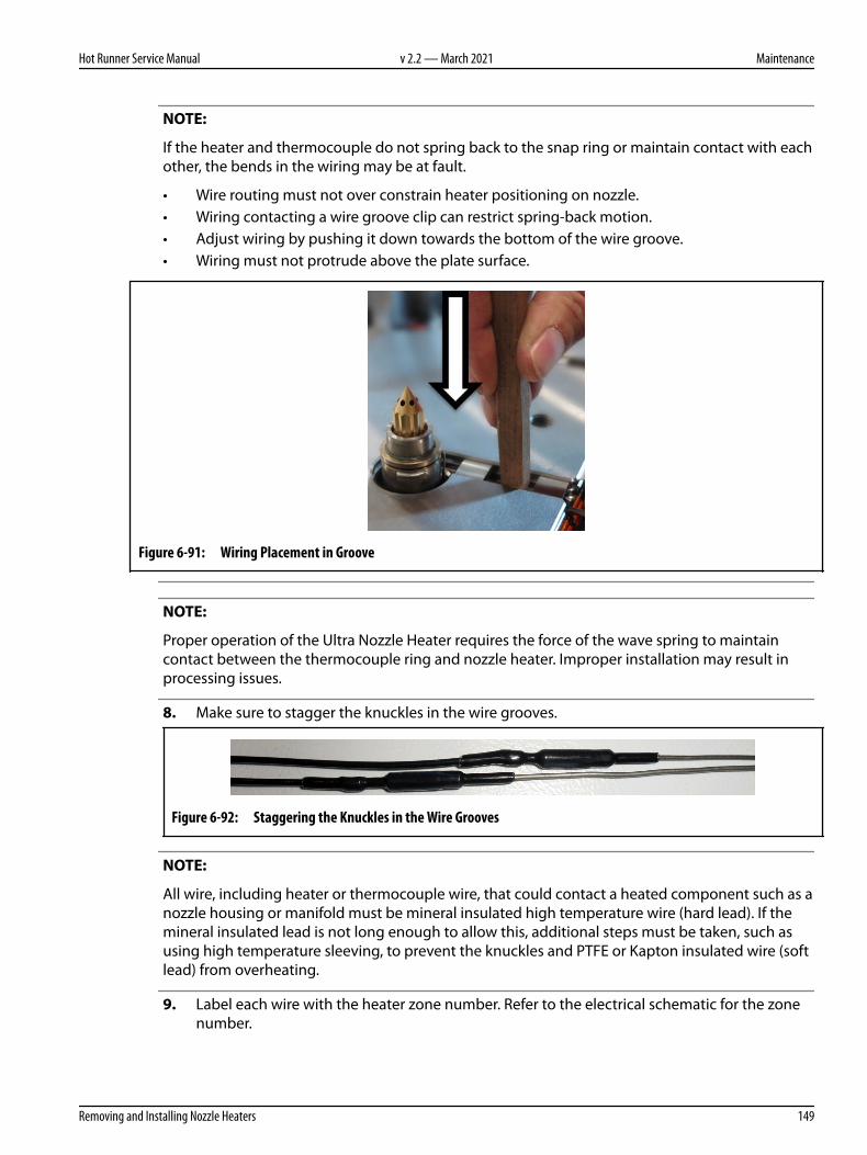
NOTE:
If the heater and thermocouple do not spring back to the snap ring or maintain contact with eachother, the bends in the wiring may be at fault.
• Wire routing must not over constrain heater positioning on nozzle.• Wiring contacting a wire groove clip can restrict spring-back motion.• Adjust wiring by pushing it down towards the bottom of the wire groove.• Wiring must not protrude above the plate surface.
Figure 6-91: Wiring Placement in Groove
NOTE:
Proper operation of the Ultra Nozzle Heater requires the force of the wave spring to maintaincontact between the thermocouple ring and nozzle heater. Improper installation may result inprocessing issues.
8. Make sure to stagger the knuckles in the wire grooves.
Figure 6-92: Staggering the Knuckles in the Wire Grooves
NOTE:
All wire, including heater or thermocouple wire, that could contact a heated component such as anozzle housing or manifold must be mineral insulated high temperature wire (hard lead). If themineral insulated lead is not long enough to allow this, additional steps must be taken, such asusing high temperature sleeving, to prevent the knuckles and PTFE or Kapton insulated wire (softlead) from overheating.
9. Label each wire with the heater zone number. Refer to the electrical schematic for the zonenumber.
Hot Runner Service Manual v 2.2 — March 2021 Maintenance
Removing and Installing Nozzle Heaters 149

10. Crimp the wire ends and connect the wires to the appropriate multi-pin connectors. Refer tothe electrical schematic for more information.
11. Test each nozzle heater. Refer to Section 6.5 for more information.12. Remove all locks and tags. Refer to Section 2.5 for more information.
6.17.6 Removing and Installing Bi-Metal Nozzle Heaters
The following procedures describe how in remove and install bi-metal nozzle heaters.
6.17.6.1 Removing Bi-Metal Nozzle Heaters
To replace a bi-metal nozzle heater, do the following:
1. Separate or remove the cavity plate from the hot runner. Refer to Section 6.6 for moreinformation.
2. Remove the front ring.
1
3
45
6
2
Figure 6-93: Bi-Metal Nozzle Heater Assembly
1. Front Ring 2. Retaining Sleeve (If Equipped) 3. Retaining Clip 4. Bi-Metal NozzleHeater 5. Thermocouple 6. Nozzle Tip
3. Disconnect the thermocouple from the nozzle heater.4. Remove the retaining clip from the nozzle tip.5. Remove the necessary wire clips to expose the nozzle heater and thermocouple wires.6. Remove the nozzle heater and thermocouple.
6.17.6.2 Installing Bi-Metal Nozzle Heaters
To install a bi-metal nozzle heater, do the following:
1. Slide the nozzle heater over the nozzle housing and nozzle tip.
v 2.2 — March 2021 Ultra Valve Gate Hot Runner
150 Removing and Installing Bi-Metal Nozzle Heaters

1
34
2
5
Figure 6-94: Bi-Metal Nozzle Heater Assembly
1. Front Ring 2. Retaining Clip 3. Bi-Metal Nozzle Heater 4. Thermocouple 5. Nozzle Tip
2. Install the retaining clip around the nozzle tip.3. Connect the thermocouple to the nozzle heater.4. Pull the nozzle heater up against the retaining clip.5. Install the front ring and tighten by hand.6. Route the nozzle heater and thermocouple wires through the wire channels in the manifold
plate. Make sure all wiring is properly retained in the wire channels using wire clips.7. Make sure to stagger the knuckles in the wire grooves.
Figure 6-95: Staggering the Knuckles in the Wire Grooves
NOTE:
All wire, including heater or thermocouple wire, that could contact a heated component such as anozzle housing or manifold must be mineral insulated high temperature wire (hard lead). If themineral insulated lead is not long enough to allow this, additional steps must be taken, such asusing high temperature sleeving, to prevent the knuckles and PTFE or Kapton insulated wire (softlead) from overheating.
8. Label each wire with the heater zone number. Refer to the electrical schematic for the zonenumber.
9. Crimp the wire ends and connect the wires to the appropriate multi-pin connectors. Refer tothe electrical schematic for more information.
10. Test each nozzle heater. Refer to Section 6.5 for more information.
6.17.7 Removing and Installing VG-HP Nozzle Heaters
The following procedures describe how to remove and install VG-HP nozzle heaters.
Hot Runner Service Manual v 2.2 — March 2021 Maintenance
Removing and Installing Nozzle Heaters 151
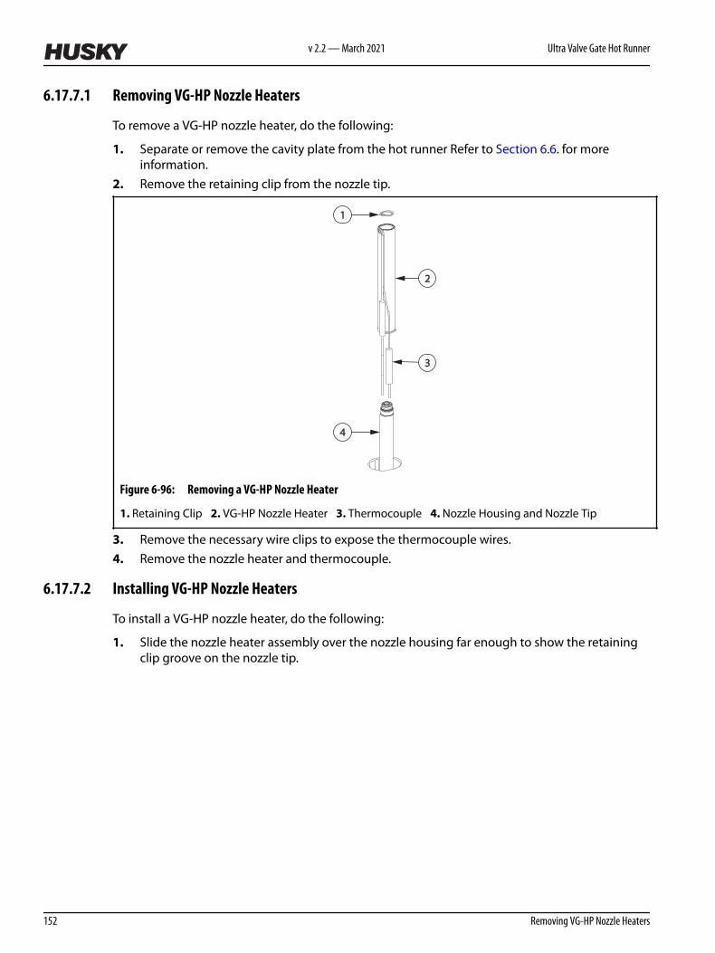
6.17.7.1 Removing VG-HP Nozzle Heaters
To remove a VG-HP nozzle heater, do the following:
1. Separate or remove the cavity plate from the hot runner Refer to Section 6.6. for moreinformation.
2. Remove the retaining clip from the nozzle tip.
2
4
1
3
Figure 6-96: Removing a VG-HP Nozzle Heater
1. Retaining Clip 2. VG-HP Nozzle Heater 3. Thermocouple 4. Nozzle Housing and Nozzle Tip
3. Remove the necessary wire clips to expose the thermocouple wires.4. Remove the nozzle heater and thermocouple.
6.17.7.2 Installing VG-HP Nozzle Heaters
To install a VG-HP nozzle heater, do the following:
1. Slide the nozzle heater assembly over the nozzle housing far enough to show the retainingclip groove on the nozzle tip.
v 2.2 — March 2021 Ultra Valve Gate Hot Runner
152 Removing VG-HP Nozzle Heaters

2
4
1
3
Figure 6-97: VG-HP Nozzle Heater Assembly
1. Retaining Clip 2. VG-HP Nozzle Heater 3. Thermocouple 4. Nozzle Housing and Nozzle Tip
2. Install the retaining clip on the nozzle tip and pull the nozzle heater assembly up against it.3. Route the thermocouple wires through the wire channels in the manifold plate. Make sure all
wiring is properly retained in the wire channels using wire clips.4. Make sure to stagger the knuckles in the wire grooves.
Figure 6-98: Staggering the Knuckles in the Wire Grooves
NOTE:
All wire, including heater or thermocouple wire, that could contact a heated component such as anozzle housing or manifold must be mineral insulated high temperature wire (hard lead). If themineral insulated lead is not long enough to allow this, additional steps must be taken, such asusing high temperature sleeving, to prevent the knuckles and PTFE or Kapton insulated wire (softlead) from overheating.
5. Label each wire with the heater zone number. Refer to the electrical schematic for the zonenumber.
6. Crimp the wire ends and connect the wires to the appropriate multi-pin connectors. Refer tothe electrical schematic for more information.
7. Test each nozzle heater. Refer to Section 6.5 for more information.
Hot Runner Service Manual v 2.2 — March 2021 Maintenance
Removing and Installing Nozzle Heaters 153

6.18 Removing and Installing Nozzle Tip Insulators (If Equipped)
Nozzle tip insulators protect the gate details and nozzle tips from damage and prevent resin leaks.
The following procedures describe how to remove and install nozzle tip insulators.
6.18.1 Removing the Nozzle Tip Insulators
To remove the nozzle tip insulators, do the following:
WARNING!
Burn hazard – risk of serious injury. To avoid serious burns, wear personal protectiveequipment consisting of a heat-resistant coat, heat-resistant gloves, and a full face shieldover safety glasses. Use adequate ventilation for fumes.
1. Separate the cavity plate from the hot runner. Refer to Section 6.6 for more information.
NOTE:
Some nozzle tip insulators may remain in the gate detail in the cavity plate.
2. Lock out and tag the machine. For machine lockout and tag procedures refer to the machinedocumentation.
IMPORTANT!
Due to geometric variations between the gate details and the witness marks left in the nozzle tipinsulators by the nozzle tips, Husky does not recommend reusing nozzle tip insulators. Previouslyused nozzle tip insulators should always be replaced with new nozzle tip insulators. If reuse isabsolutely necessary (i.e. unscheduled maintenance with no spares on hand), order new nozzletip insulators and replace as soon as possible. Contact your nearest Husky Regional Service andSales Office or www.husky.co.
IMPORTANT!
Nozzle tip insulators form to the dimensions of the nozzle tip and gate detail when compressed.Before removing a nozzle tip, make sure to record the nozzle tip location and the orientation ofthe nozzle tip insulator. This will help avoid resin leakage if the nozzle tip insulators are reused.
3. If nozzle tips must be reused, record the position and orientation of each nozzle tip insulator.
v 2.2 — March 2021 Ultra Valve Gate Hot Runner
154 Removing and Installing Nozzle Tip Insulators (If Equipped)

CAUTION!
Mechanical hazard – risk of equipment damage. Do not allow molten resin to drop onnozzle tip insulators while the insulators are being removed. The additional material willincrease the calculated preload for the nozzle tip insulator and damage the hot runnerduring assembly with the cavity plate.
Make sure all nozzle tip insulators are clean during removal and installation.
4. Remove the nozzle tip insulators from the nozzle tips using needle nose pliers. Be careful notto damage the nozzle tips or sealing surfaces.
5. If a nozzle tip insulator is found in the gate detail in the cavity plate, remove the nozzle tipinsulator using a 10 mm or 3/8”‑18 NPT tap or pipe and then clean the gate.
Clean the gate detail using a pointed hardwood stick and soft cloth, or a Scotch‑Brite No.7447 (Maroon). Care must be taken not to scratch the cylindrical sealing surfaces betweenthe gate insert and nozzle housing. Even a slight scratch may cause leaks at high injectionpressures.
6. Inspect the nozzle tip insulators for resin. If resin is found, the nozzle tip insulator is leakingand will not function as required.
Determine the following:
• The cause of the leak by inspecting the gate insert dimensions.• The nozzle tip position to make sure it is correct before a new insulator is installed.
7. Remove all locks and tags.
6.18.2 Installing the Nozzle Tip Insulators
To install the nozzle tip insulators, do the following:
IMPORTANT!
Due to geometric variations between the gate details and the witness marks left in the nozzle tipinsulators by the nozzle tips, Husky does not recommend reusing nozzle tip insulators. Previouslyused nozzle tip insulators should always be replaced with new nozzle tip insulators. If reuse isabsolutely necessary (i.e. unscheduled maintenance with no spares on hand), order new nozzletip insulators and replace as soon as possible. Contact your nearest Husky Regional Service andSales Office or www.husky.co.
CAUTION!
Mechanical hazard – risk of damage to the hot runner. Make sure all nozzle tip insulatorsare clean before they are installed. Any additional material on the nozzle tip insulator willincrease the calculated preload and damage the hot runner during assembly with thecavity plate.
Hot Runner Service Manual v 2.2 — March 2021 Maintenance
Removing and Installing Nozzle Tip Insulators (If Equipped) 155

1. Make sure the hot runner is either installed in the machine or laying on a work bench withthe nozzle tips facing up.
2. Make sure all nozzle tip insulators are clean and in good condition.
CAUTION!
Mechanical hazard – risk of damage to the hot runner. Nozzle tip insulators form to thedimensions of the nozzle tip and gate detail when compressed. Make sure previously usednozzle tips are installed on the same nozzle tip in the same orientation. Resin leakage willoccur otherwise.
3. Place a nozzle tip insulator on each nozzle tip. If used nozzle tip insulators are being installed,make sure they are installed on the same nozzle tip as previously removed and in the sameorientation.
Figure 6-99: Nozzle Tip Insulator
4. Make sure there are no nozzle tip insulators in the gate inserts.5. Install the cavity plate. Refer to Section 6.6 for more information.
6.19 Removing Insulating Gate Bubbles (If Equipped)
In place of nozzle tip insulators, some hot runners form a bubble of resin at the nozzle tip referredto as an insulating gate bubble. The bubbles provide thermal insulation between the nozzle tipand the cold cavity plate steel. They also increase the speed of color changes and prevent thedegradation of some heat sensitive resins. The gate bubble needs to be removed if the gate holeis blocked by contamination.
v 2.2 — March 2021 Ultra Valve Gate Hot Runner
156 Removing Insulating Gate Bubbles (If Equipped)

1
Figure 6-100: Gate Bubbles
1. Gate Bubbles
To remove the insulating gate bubbles, do the following:
1. Remove the cavity plate. Refer to Section 6.6 for more information.2. Connect the hot runner to a controller.3. Turn on the controller.
DANGER!
Electrocution hazard – risk of serious injury and/or damage to the hot runner. Do not turnon the heaters if water has leaked into the hot runner. If water has leaked into the hotrunner, the hot runner must be completely disassembled, dried and assembled before theheaters are turned on.
WARNING!
Hot resin spray hazard – risk of serious injury. Hot resin may unexpectedly spray from thenozzle tips while the hot runner is reaching operating temperature. To avoid serious burns,wear personal protective equipment consisting of a heat-resistant coat, heat-resistantgloves and a full face shield over safety glasses. Use adequate ventilation for fumes.
WARNING!
Burn hazard – risk of serious injury. Hot runner components stay hot for long periods oftime after heaters have been turned off. Wear personal protective equipment whenworking near the hot runner and place a warning sign in the area before leaving the hotrunner unattended.
4. Increase the temperature of a row of nozzle tips to a temperature high enough to soften theinsulating gate bubble.
Hot Runner Service Manual v 2.2 — March 2021 Maintenance
Removing Insulating Gate Bubbles (If Equipped) 157

NOTE:
The Vicat Softening Temperature for the resin type is recommended. Refer to the resin supplier’sdocumentation for more information.
5. Once the nozzle tips have reached their setpoint approximately 120 °C (248 °F), wait until thegate bubble on the first nozzle tip is soft enough to remove and then turn off all the nozzletip heaters.
WARNING!
Electrocution hazard - risk of death or serious injury. Complete the lockout/tagoutprocedure of the electrical power source before disconnecting the electrical connectors.
6. Lock out and tag the electrical power source.
IMPORTANT!
Do not allow the nozzle tips to overheat or degraded material will have to be cleaned out of thenozzle housing before a new nozzle tip can be installed.
7. Disconnect the controller.8. Remove all gate bubbles from the row with brass pliers, a clean cloth or a soft wire brush.9. Repeat step 4 to step 8 for all subsequent rows.
WARNING!
Burn, fire and gas hazard – risk of death or serious injury, and property damage. Use of anopen flame to remove resin could produce harmful gases (depending on the resin type),damage components and increase the risk of fire. Only use open flames sparingly and in acontrolled environment.
WARNING!
Burn hazard – risk of serious injury. To avoid serious burns, wear personal protectiveequipment consisting of a heat-resistant coat, heat-resistant gloves, and a full face shieldover safety glasses. Use adequate ventilation for fumes.
CAUTION!
Mechanical hazard – risk of damage to the equipment. Abrasives should never be used toclean the nozzle tips, as this could damage the critical sealing surfaces.
Do not remove the gate bubble with a hammer or tools made of hard material. Use toolsmade of soft materials such as brass, copper or wood. Hammering or using hard materialtools could result in damage to the nozzle tips.
v 2.2 — March 2021 Ultra Valve Gate Hot Runner
158 Removing Insulating Gate Bubbles (If Equipped)

10. Remove any insulating gate bubbles in the cavity plate. If required, carefully heat the gatebubbles with a propane torch and then wipe the deposits away with a clean, soft cloth orsoft wire brush. This may have to be repeated several times.
CAUTION!
Mechanical hazard – risk of damage to the hot runner. Do not allow molten resin to drop onor build up under the nozzle tip insulators while the gate bubbles are being removed. Theadditional material will increase the calculated preload for the nozzle tip insulator anddamage the hot runner during assembly with the cavity plate.
Make sure all nozzle tip insulators are clean and seated correctly before installing the cavityplate.
11. Make sure all nozzle tip insulators (if equipped) are seated correctly with a minimal and evengap between the nozzle tip insulator and the nozzle housing. For reused nozzle tips, the gapmay not be noticeable. When plastic is under the nozzle tip insulator, it will have a largerthan usual and/or uneven gap in relation to the nozzle housing. If plastic is under the nozzletip insulator it must be cleaned or replaced. For more information on removing and installingthe nozzle tip insulator refer to Section 6.18.
Figure 6-101: Seating the Nozzle Tip Insulator (Example)
To remove, clean and install the nozzle tip insulator, do the following:
a. Mark the orientation of the nozzle tip insulator.b. Remove the nozzle tip insulator.
IMPORTANT!
If the nozzle tip insulator is damaged or cannot be cleaned then it must be replaced.
c. Clean the nozzle tip insulator by heating to melt the residual plastic and wiping it clean.d. Install the nozzle tip insulator. Nozzle tip insulators must be installed on the same
nozzle tip in the original orientation.12. Make sure the hot runner is at room temperature <25 °C (<77 °F).
Hot Runner Service Manual v 2.2 — March 2021 Maintenance
Removing Insulating Gate Bubbles (If Equipped) 159

NOTE:
If the hot runner is still in the machine the cooling water can be turned on to cool the hot runnerdown.
13. Install the cavity plate. Refer to Section 6.6 for more information.
6.20 Removing and Installing Manifold Bushings
The following procedures describe how to remove, maintain and install manifold bushings.
Manifold bushings need to be replaced if the following occurs:
• The valve stem is stuck and cannot be removed• The valve stem bore is worn and leaking heavily back into the actuation area• The manifold bushing is collapsed from overheating• The air seal face is damaged• The manifold bushing is damaged in a way that renders it unusable
NOTE:
Husky provides two styles of manifold bushings: press fit or slip fit. Press fit manifold bushings aretypically used in systems designed to process heat-sensitive resins. Slip fit manifold bushings areused in systems designed to process resins that are not heat-sensitive. Refer to the assemblydrawings to determine if the manifold bushings are press fit or slip fit.
6.20.1 Removing and Installing Press Fit Manifold Bushings
It is recommended that press fit bushings be removed and replaced by Husky. Contact yourHusky Regional Service and Sales office for more information about removing press fit manifoldbushings.
6.20.2 Removing Slip Fit Manifold Bushings
To remove slip fit manifold bushings, do the following:
1. Disconnect the manifold and thermocouple wires from the manifolds.2. Remove the nozzle heaters and thermocouples. Refer to Section 6.17 for more information.3. Remove the nozzle tips. Refer to Section 6.14 for more information.4. Remove the nozzle housings. Refer to Section 6.16 for more information.5. Remove the manifold from the manifold plate pocket. Refer to Section 6.9.2 for more
information.6. Press the manifold bushings out of the manifold using a heavy brass punch. Take care not to
damage the bushings or manifold.
v 2.2 — March 2021 Ultra Valve Gate Hot Runner
160 Removing and Installing Manifold Bushings

2
4
1
3
Figure 6-102: Removing a Manifold Bushing (Typical)
1. Manifold 2. Locating Dowel 3. Manifold Bushing 4. Heavy Brass Punch
6.20.3 Installing Slip Fit Manifold Bushings
To install slip fit manifold bushings, do the following:
1. Remove any resin from the manifold bushing pockets and seating area in the manifold plateusing brass scrapers. Do not damage the sharp corners or sealing surfaces.
2. Remove any resin from the exterior of the manifold bushings with brass scrapers. Do notdamage the sharp corners or sealing surfaces.
3. Make sure the interior of the manifold bushing is free of resin.4. Clean the stem bore in the manifold bushing with alcohol and cotton swabs. The interior is
clean when a cotton swab can be removed from the bushing without any dirt on it.5. Use a medium India stone (240 grit oil stone) to clean all mating surfaces on the manifold.
Do not scratch the manifold.6. Check that all contact surfaces on the manifold plate, center plate or air plate and manifold
bushings are clean and free of residue, scratches, nicks, or burrs.7. Make sure the manifold bushing locating dowel is installed in the manifold.
Hot Runner Service Manual v 2.2 — March 2021 Maintenance
Removing and Installing Manifold Bushings 161

2
1
3
Figure 6-103: Installing a Manifold Bushing (Typical)
1. Manifold 2. Locating Dowel 3. Manifold Bushing
8. Align the manifold bushing with the locating dowel and press the bushing into the manifolduntil the bushing bottoms out on the manifold. Repeat this step for all manifold bushings.
6.21 Removing and Installing the Sprue Heater (If Equipped)
The following procedures describe how to remove and install a sprue heater with a built-inthermocouple or a separate thermocouple.
6.21.1 Removing a Sprue Heater with a Built-In Thermocouple
To remove a sprue heater that has a built-in thermocouple, do the following:
1. If necessary, remove the hot runner from the machine. Refer to Section 4.3 for moreinformation.
2. If a center plate is not equipped, remove the backing plate. Refer to Section 6.7 for moreinformation.
3. Disconnect the sprue heater and thermocouple wires from the multi-pin connectors.
1
4
3
2
1
Figure 6-104: Removing the Sprue Heater
1. Retaining Clip 2. Lead Exit 3. Sprue Heater and Thermocouple 4. Sprue Bushing
v 2.2 — March 2021 Ultra Valve Gate Hot Runner
162 Removing and Installing the Sprue Heater (If Equipped)

4. Remove the sprue heater and thermocouple wires from the wire channels in the manifoldplate.
5. Remove the retaining clip from the sprue bushing.6. Remove the sprue heater and thermocouple from the sprue bushing.
6.21.2 Removing a Sprue Heater with a Separate Thermocouple
To remove a sprue heater that has a separate thermocouple, do the following:
1. If necessary, remove the hot runner from the machine. Refer to Section 4.3 for moreinformation.
2. If a center plate is not equipped, remove the backing plate. Refer to Section 6.7 for moreinformation.
3. Disconnect the sprue heater and thermocouple wires from the multi-pin connectors.
1
2
3
4 5
Figure 6-105: Removing the Sprue Heater
1. Front Ring 2. Retaining Clip 3. Sprue Heater 4. Sprue Bushing 5. Thermocouple
4. Remove the sprue heater and thermocouple wires from the wire channels in the manifoldplate.
5. Remove the front ring, retaining clip and thermocouple.6. Using a heater removal tool, remove the sprue heater from the sprue bushing. Refer to
Section 1.8 for a list of special Husky tools and order numbers.
6.21.3 Installing a Sprue Heater with a Built-In Thermocouple
To install a sprue heater with a built-in thermocouple, do the following:
1. If there are two retaining clip grooves, install a retaining clip in the groove closest to themanifold.
Hot Runner Service Manual v 2.2 — March 2021 Maintenance
Removing and Installing the Sprue Heater (If Equipped) 163

2. With the lead exit facing away from the manifold, slide the sprue heater onto the spruebushing. Make sure the sprue heater is below the retaining clip groove in the sprue bushing.
1
4
3
2
1
Figure 6-106: Installing the Sprue Heater
1. Retaining Clip 2. Lead Exit 3. Sprue Heater and Thermocouple 4. Sprue Bushing
3. Align the heater and thermocouple wires with the wire channels in the backing plate.4. Install the retaining clip into the groove on the sprue bushing.5. Pull the sprue heater up until it makes contact with the retaining clip.
NOTE:
All wiring near the sprue heater must be either a high temperature braid or sleeved using a hightemperature sleeving.
6. Route the sprue heater and thermocouple wires through the wire channels in the manifoldplate. Make sure all wiring is properly retained in the wire channels using wire clips.
If the wire length is too long or too short, refer to Section 6.24 for information aboutadjusting the wire length.
7. Label each wire with the heater zone number. Refer to the electrical schematic for the zonenumber.
8. Crimp the wire ends and connect them to the appropriate multi-pin connectors. Refer to theelectrical schematic for more information.
9. Test the sprue heater. Refer to Section 6.5 for more information.10. If a center plate is not equipped, install the backing plate. Refer to Section 6.7.2 for more
information.
6.21.4 Installing a Sprue Heater with a Separate Thermocouple
To install a sprue heater with a separate thermocouple, do the following:
1. Slide the sprue heater onto the sprue bushing. Make sure the sprue heater is below theretaining clip groove in the sprue bushing.
v 2.2 — March 2021 Ultra Valve Gate Hot Runner
164 Installing a Sprue Heater with a Separate Thermocouple

1
2
3
4 5
Figure 6-107: Installing the Sprue Heater
1. Front Ring 2. Retaining Clip 3. Sprue Heater 4. Sprue Bushing 5. Thermocouple
2. Install the retaining clip into the groove on the sprue bushing.3. Using a heater removal tool, pull the sprue heater up until it makes contact with the
retaining clip. Refer to Section 1.8 for a list of special Husky tools and order numbers.
NOTE:
All wiring near the sprue heater must be either a high temperature braid or sleeved using a hightemperature sleeving.
4. Connect the thermocouple to the sprue heater.5. Route the sprue heater and thermocouple wires through the wire channels in the manifold
plate. Make sure all wiring is properly retained in the wire channels using wire clips.
If the wire length is too long or too short, refer to Section 6.24for information aboutadjusting the wire length.
6. Thread the front ring onto the sprue heater and tighten by hand.7. Label each wire with the heater zone number. Refer to the electrical schematic for the zone
number.8. Crimp the wire ends and connect them to the appropriate multi-pin connectors. Refer to the
electrical schematic for more information.9. Test the sprue heater. Refer to Section 6.5 for more information.10. If a center plate is not equipped, install the backing plate. Refer to Section 6.7.2 for more
information.
Hot Runner Service Manual v 2.2 — March 2021 Maintenance
Removing and Installing the Sprue Heater (If Equipped) 165

6.22 Removing and Installing the Sprue Bushing
The following procedures describe how to remove, maintain and install the sprue bushing.
6.22.1 Removing the Sprue Bushing
To remove the sprue bushing, do the following:
1. Remove the hot runner from the machine. Refer to Section 4.3 for more information.2. Remove the backing plate. Refer to Section 6.7 for more information.3. If equipped, remove the center plate. Refer to Section 6.8.1 for more information.4. Remove the sprue heater. Refer to Section 6.21 for more information.5. Remove the screws that secure the sprue bushing to the manifold.
1
2
Figure 6-108: Removing the Sprue Bushing
1. Sprue Bushing 2. Screw
6. Remove the sprue bushing.7. Using a brass rod, remove the resin slug from the sprue bushing melt channel.8. Clean the sprue bushing. Do not damage any sealing surfaces.9. Check and repair the nozzle radius, if required.
6.22.2 Installing the Sprue Bushing
To install the sprue bushing, do the following:
WARNING!
Hot resin spray hazard – risk of serious injury. Any contamination or damage at the spruebushing and manifold interface could cause hot resin to spray out of the mold, possiblyresulting in serious burns. Both the mounting faces of the sprue bushing and manifoldmust be spotlessly clean and undamaged. The mounting screws must also be torqued tothe specified value.
v 2.2 — March 2021 Ultra Valve Gate Hot Runner
166 Removing and Installing the Sprue Bushing

NOTE:
The supplied screws used to install the sprue bushing are of a special quality and must not besubstituted.
1. Clean the surfaces on the sprue bushing and manifold where the two components willinterface.
1
2
3
4
Figure 6-109: Sprue Bushing and Manifold Sealing Faces
1. Manifold 2. Spigot Pocket Face 3. Spigot Face 4. Locating Diameters
CAUTION!
Crushing hazard – risk of damage to equipment. Screws used to install sprue bushings mustmeet specific requirements. Only use the screws specified in the assembly drawings. Failureto use these screws may result in equipment damage.
2. Apply a high temperature anti-seize lubricant to the screws used to install the sprue bushing.Refer to Section 3.5 for information about recommended lubricants.
1
2
Figure 6-110: Installing the Sprue Bushing
1. Sprue Bushing 2. Screw
Hot Runner Service Manual v 2.2 — March 2021 Maintenance
Removing and Installing the Sprue Bushing 167

3. Install the sprue bushing and torque all screws to half the specified value in a cross pattern.Refer to the assembly drawings for torque requirements.
4. Torque the screws fully to the specified value to make sure an even seal is made between thesprue bushing and manifold. Refer to the assembly drawings for torque requirements.
5. Install the sprue heater. Refer to Section 6.21 for more information.6. If equipped, install the center plate. Refer to Section 6.8.2 for more information.7. Install the backing plate. Refer to Section 6.7.2 for more information.8. Install the hot runner into the machine. Refer to Section 4.3.1 for more information.
6.23 Removing and Installing Transfer Bushings (If Equipped)
The following procedures describe how to remove and install transfer bushings.
6.23.1 Removing Transfer Bushings (If Equipped)
To remove a transfer bushing, do the following:
1. Remove the transfer bushing cover plates.
1
2
Figure 6-111: Removing the Transfer Bushing Cover Plates
1. Cover Plate 2. Screw
2. Remove the center plate. Refer to Section 6.8.1 for more information.3. Disconnect the transfer bushing heater and thermocouple wires from the multi-pin
connectors.
v 2.2 — March 2021 Ultra Valve Gate Hot Runner
168 Removing and Installing Transfer Bushings (If Equipped)

6
5
3
1
4
2
Figure 6-112: Transfer Bushing Assembly
1. Retaining Ring 2. Thermocouple Retaining Ring 3. Transfer BushingHeater 4. Springs 5. Screw 6. Transfer Bushing
4. Remove the transfer bushing heater and thermocouple wires from the wire channels in themanifold plate.
5. Remove the retaining clip from the transfer bushing.6. Remove the thermocouple retaining ring from the heater.7. Remove the heater and springs.8. Inspect the springs for wear, corrosion, cracks or other damage. Replace the springs if
necessary.9. Remove the screws that secure the transfer bushing to the manifold.10. Remove the transfer bushing.11. Using a brass rod, remove the resin slug from the transfer bushing melt channel.12. Clean the transfer bushing. Do not damage any sealing surfaces.
6.23.2 Installing Transfer Bushings (If Equipped)
To Install a transfer bushing, do the following:
NOTE:
The supplied screws used to install the transfer bushing are of a special quality and must not besubstituted.
1. Clean the surfaces on the transfer bushing and manifold where the two components willinterface.
Hot Runner Service Manual v 2.2 — March 2021 Maintenance
Removing and Installing Transfer Bushings (If Equipped) 169

1
2
3
4
Figure 6-113: Transfer Bushing and Manifold Sealing Faces
1. Manifold 2. Spigot Pocket Face 3. Spigot Face 4. Locating Diameters
CAUTION!
Crushing hazard – risk of damage to equipment. Screws used to install transfer bushingsmust meet specific requirements. Only use the screws specified in the assembly drawings.Failure to use these screws may result in equipment damage.
2. Apply a high temperature anti-seize lubricant to the screws used to install the transferbushing. Refer to Section 3.5 for information about recommended lubricants.
6
5
3
1
4
2
Figure 6-114: Transfer Bushing Assembly
1. Retaining Ring 2. Thermocouple Retaining Ring 3. Transfer Bushing Heater 4. Springs 5. Screw 6. Transfer Bushing
3. Install the transfer bushing and torque all screws to half the specified value in a cross pattern.Refer to the assembly drawings for torque requirements.
4. Torque the screws fully to the specified value to make sure an even seal is made between thetransfer bushing and manifold. Refer to the assembly drawings for torque requirements.
5. Slide springs onto the transfer bushing.
v 2.2 — March 2021 Ultra Valve Gate Hot Runner
170 Removing and Installing Transfer Bushings (If Equipped)

6. Slide the transfer bushing heater onto the transfer bushing. Make sure the transfer bushingheater is below the retaining clip groove in the transfer bushing.
7. Snap the thermocouple ring onto the transfer bushing heater.8. Install the retaining clip into the groove on the transfer bushing.
NOTE:
All wiring near the transfer bushing heater must be either a high temperature braid or sleevedusing a high temperature sleeving.
9. Route the transfer bushing heater and thermocouple wires through the wire channels in themanifold plate. Make sure all wiring is properly retained in the wire channels using wire clips.
If the wire length is too long or too short, refer to Section 6.24for information aboutadjusting the wire length.
10. Label each wire with the heater zone number. Refer to the electrical schematic for the zonenumber.
11. Crimp the wire ends and connect them to the appropriate multi-pin connectors. Refer to theelectrical schematic for more information.
12. Test the transfer bushing heater. Refer to Section 6.5 for more information.13. Install the center plate. Refer to Section 6.8.2 for more information.14. Install the transfer bushing cover plates.
1
2
Figure 6-115: Installing the Transfer Bushing Cover Plates
1. Cover Plate 2. Screw
15. Install the backing plate. Refer to Section 6.7.2 for more information.
6.24 Adjusting the Thermocouple Wire Length
In some cases, the length of a thermocouple wire may be too long or too short depending on thesize of the hot runner. The following are recommendations for adjusting the wire length:
1. Long Thermocouple Wires
Hot Runner Service Manual v 2.2 — March 2021 Maintenance
Removing and Installing Transfer Bushings (If Equipped) 171

For small hot runners where the lead length is greater than required, wrap the wires aroundthe heater body to reduce slack and make sure the wires fit properly in the wire channel.
Figure 6-116: Wire Wrapped Around Sprue Heater (Example)
2. Short Thermocouple Wires
For large hot runners where the lead length is insufficient to reach a wire channel, cut andinstall a length of fiberglass sleeving to protect the wire.
Figure 6-117: Fiberglass Sleeving (Example)
6.25 Removing Air and Water Plugs
IMPORTANT!
Husky does not recommend the removal of seized air and water plugs in the field. Contact Huskyto arrange returning the hot runner for repair and/or rework. This procedure was prepared byHusky at the request of the customer, and does not in any way absolve the customer fromfulfilling their usual obligations, including those mentioned above. Husky disclaims liability fordamage to property or injury to personnel caused by the customer attempting the procedure. Itis the obligation of the customer to confirm that personnel are trained and have appropriatequalifications including: understanding the safe methods and using the correct personalprotective equipment prior to performing this procedure.
v 2.2 — March 2021 Ultra Valve Gate Hot Runner
172 Removing Air and Water Plugs

WARNING!
Burn and mechanical hazard - risk of serious injury and/or damage to the equipment. Onlyqualified personnel should perform this procedure using the appropriate personalprotective equipment.
WARNING!
Burn hazard – risk of serious injury. To avoid serious burns, do not touch the plate or plugafter heating and wear personal protective equipment consisting of a heat-resistant coat,heat-resistant gloves, and a full face shield over safety glasses.
1. Heat the plate area surrounding the stainless steel plug with a hand held torch for 1-2minutes. Do not heat the plug directly.
IMPORTANT!
Do not use an impact gun or impact driver as the plug will seize.
2. Once the plate is heated, use a safety-rated breaker bar and the appropriate Hex socketadapter to apply pressure and back the plug out.
If the plug does not move, repeat step 1 and step 2.3. If the plug cannot be removed manually using step 1 and step 2, the use of a magnetic drill
or milling out the plug will be required.
If you are unable to safely remove the plug as described in this procedure, return the part toHusky for rework and/or repair. Contact Husky for more information.
IMPORTANT!
Do not use an impact gun or impact driver as the plug will seize.
4. Clean the threads on the plug and then, if required, apply the appropriate plug sealant to thethreads.
5. Install the new plug. Refer to Table 6-1 for the recommended torque. Contact Husky forappropriate part number
Table 6-1: Pipe Threads, Taps and Torques
Pipe Thread†STAINLESS STEEL
Tap Drill Torque
1 - 11 1/2 29.36 mm (1.156 in) 108 N·m (80 lbf·ft)
1 1/4 - 11 1/2 38.10 mm (1.50 in) 136 N·m (100 lbf·ft)
1 1/2 - 11 ½ 44.05 mm (1.734 in) 163 N·m (120 lbf·ft)
Hot Runner Service Manual v 2.2 — March 2021 Maintenance
Removing Air and Water Plugs 173
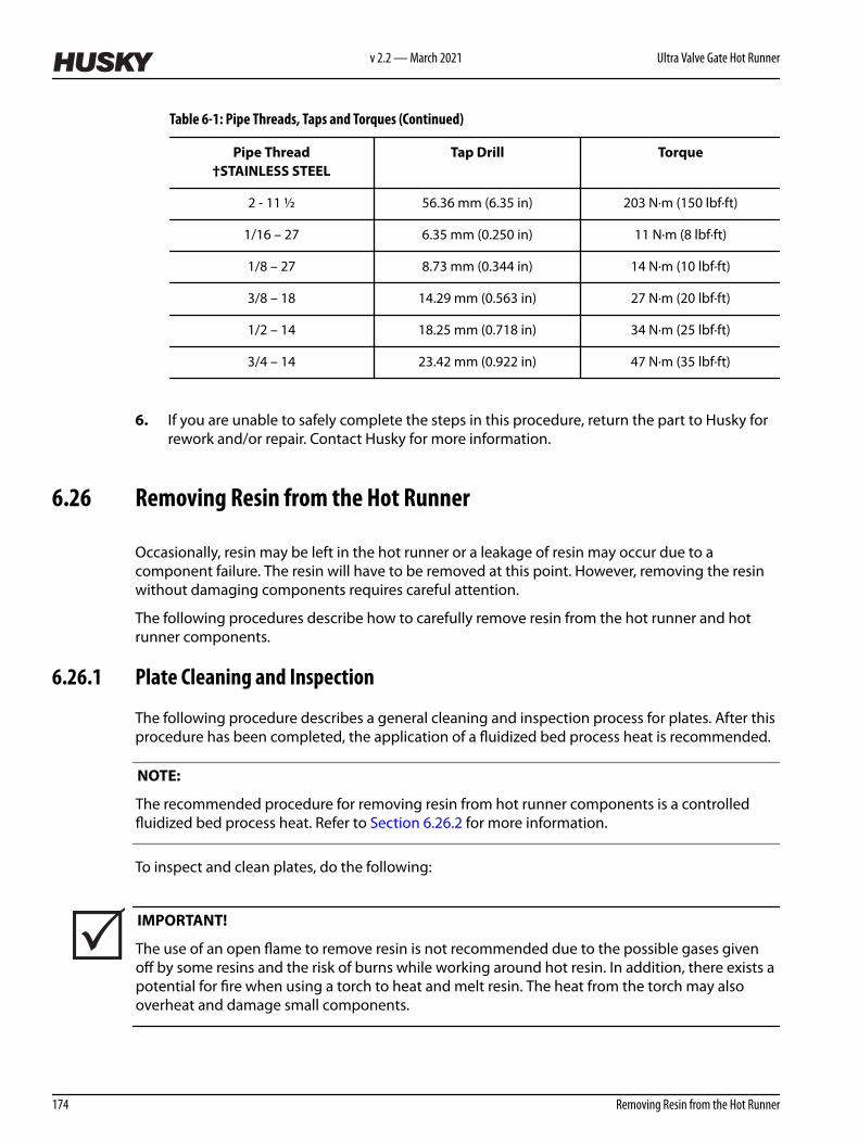
Table 6-1: Pipe Threads, Taps and Torques (Continued)
Pipe Thread†STAINLESS STEEL
Tap Drill Torque
2 - 11 ½ 56.36 mm (6.35 in) 203 N·m (150 lbf·ft)
1/16 – 27 6.35 mm (0.250 in) 11 N·m (8 lbf·ft)
1/8 – 27 8.73 mm (0.344 in) 14 N·m (10 lbf·ft)
3/8 – 18 14.29 mm (0.563 in) 27 N·m (20 lbf·ft)
1/2 – 14 18.25 mm (0.718 in) 34 N·m (25 lbf·ft)
3/4 – 14 23.42 mm (0.922 in) 47 N·m (35 lbf·ft)
6. If you are unable to safely complete the steps in this procedure, return the part to Husky forrework and/or repair. Contact Husky for more information.
6.26 Removing Resin from the Hot Runner
Occasionally, resin may be left in the hot runner or a leakage of resin may occur due to acomponent failure. The resin will have to be removed at this point. However, removing the resinwithout damaging components requires careful attention.
The following procedures describe how to carefully remove resin from the hot runner and hotrunner components.
6.26.1 Plate Cleaning and Inspection
The following procedure describes a general cleaning and inspection process for plates. After thisprocedure has been completed, the application of a fluidized bed process heat is recommended.
NOTE:
The recommended procedure for removing resin from hot runner components is a controlledfluidized bed process heat. Refer to Section 6.26.2 for more information.
To inspect and clean plates, do the following:
IMPORTANT!
The use of an open flame to remove resin is not recommended due to the possible gases givenoff by some resins and the risk of burns while working around hot resin. In addition, there exists apotential for fire when using a torch to heat and melt resin. The heat from the torch may alsooverheat and damage small components.
v 2.2 — March 2021 Ultra Valve Gate Hot Runner
174 Removing Resin from the Hot Runner
1. Using brass or hardwood scrapers, remove all resin deposits from the plates2. Remove all cooling fittings and plugs.3. Clean the deposits from the cooling hoses.
CAUTION!
Mechanical hazard – risk of equipment damage. Cleaning products such as scour pads andbrushes can be abrasive. When using pads or brushes, do not damage surfaces. To avoiddamaging surfaces, use non-abrasive products.
4. Clean the entire plate using a medium India stone (240 grit oilstone) on flat surfaces andScotch-BriteTM No. 7447 (Maroon) on difficult to reach areas
5. Remove any deposits from the alignment bushings and alignment dowels.6. Check the plate for the following:
• Wear at the alignment bushings and alignment dowels• Corrosion in the cooling channels• Cracks (especially around the mold mounting bolt holes or clamp mounting slots)• Damage to the dowel holes• Sharp edges around the wire grooves
WARNING!
Respiratory hazard – risk of serious injury. Use an appropriate breathing apparatus asprotection while using a brass wire bush or wheel. See the material safety data sheet(MSDS) from the resin supplier. As a minimum, a particle mask is recommended.
7. Rework or replace the plates as required.
NOTE:
Before re-installing components, the plate pocket(s) must be thoroughly cleaned. An electrichand drill with a brass wire wheel or a brass chisel may be used. This will prevent unnecessaryscratching.
8. Install the fittings with new pipe plugs.9. Pressure test the cooling circuits to verify there are no coolant leaks.
WARNING!
Wear appropriate eye and face protection following the recommendations of the ABMA(American Brush Manufacturers Association) and ANSI (American National StandardsInstitute) following ANSI Z87.1 “Occupational Eye and Face Protection” ANSI B165.1 andANSI B165.2 “Safety Requirements - Power Brushes”.
Hot Runner Service Manual v 2.2 — March 2021 Maintenance
Removing Resin from the Hot Runner 175

WARNING!
Respiratory hazard – risk of serious injury. Use an appropriate breathing apparatus asprotection while using a brass wire bush or wheel. See the material safety data sheet(MSDS) from the resin supplier. As a minimum, a particle mask is recommended.
10. Brush the plate surfaces with a brass wire brush and collect any dust with a vacuum.
CAUTION!
Mechanical hazard – risk of equipment damage. Cleaning products such as scour pads andbrushes can be abrasive. When using pads or brushes, do not damage, scratch, or score anysealing surfaces. To avoid damaging sealing surfaces, use non-abrasive products.
11. Clean the plate with Scotch-Brite No. 7447 (Maroon).
NOTE:
Resin on plates may also be removed using the fluidized bed cleaning process, provided that allbrass and copper components are removed from the plate and the plate assembly isdisassembled completely. Refer to Section 6.26.2 for more information.
6.26.2 Cleaning Using a Fluidized Bed Process
The following sections describe fluidized bed cleaning and how to prepare the hot runner.
Cleaning the manifold passages is rarely required. However, if necessary, manifold passages mustbe cleaned using the fluidized bed process. Only the fluidized bed cleaning process willsuccessfully remove the resin completely from the melt channels of the hot runner components.
Fluidized bed cleaning is a process with aluminum oxide particles in a high temperature retort.The heated air at 343 to 454 °C (650 to 850 °F) levitates the aluminum oxide particles creating aliquid-like behavior. The temperature and flow of the fluidized bed pyrolizes (thermallydecomposes) the polymer.
NOTE:
Husky does not recommend using a fluidized bed to clean mold plates and components.
6.26.2.1 Assistance
Husky provides a full system repair and cleaning service, in addition to helping customers find alocal fluidized bed cleaning process.
Contact your nearest Husky Regional Service and Sales office for more information.
6.26.2.2 Disassembling the Hot Runner for Fluidized Bed Cleaning
When disassembling a hot runner for fluidized bed cleaning, do the following:
v 2.2 — March 2021 Ultra Valve Gate Hot Runner
176 Cleaning Using a Fluidized Bed Process

IMPORTANT!
Before disassembling a hot runner for fluidized bed cleaning, please note the following:
• When removing resin from the mold, make sure the faces of the manifold are kept scratchfree. Scratches around the nozzle housing, valve bushing, manifold bushing and pistoncylinder, or sprue bushing/sprue bar surfaces may cause severe resin leakage.
• The thickness of the manifold(s) is extremely important for the performance of the hotrunner. There is a risk that cleaning the surface through grinding or sanding would changethe total height of the stack and thereby increase the cold clearance. This would result in aresin leak.
IMPORTANT!
The fluidized bed cleaning process will anneal Beryllium Copper (BeCu), causing rapid failure ofthe components when returned to service.
Mechanical cleaning of BeCu components must not damage any of the sealing surfaces. Use onlysoft brass, hardwood sticks, Scotch-Brite, or soft brass brushes. Do not use abrasive methods toclean BeCu components.
WARNING!
Poison hazard - risk of death or serious injury. Do not use abrasives in an open airenvironment to clean BeCu components. Airborne beryllium particles are knowncarcinogens. Only rework BeCu components using abrasives under flood coolants toprevent airborne particles.
IMPORTANT!
The Husky Warranty does not cover BeCu components used outside the operating temperaturerange, or cleaned using the fluidized bed process.
CAUTION!
Do not remove any surface or melt channel plugs. This will void the leak proof guaranteefor the hot runner. Plugs can only be removed by Husky.
1. Any system that is to be sent for fluidized bed cleaning is to be completely disassembled.However do not send the following items for cleaning:
• Set screws• Polyetheretherketone (PEEK) bushings (refer to Section 6.26.2.3) or ceramic bushings• Surface hex head plugs• Nozzle tip insulators
Hot Runner Service Manual v 2.2 — March 2021 Maintenance
Removing Resin from the Hot Runner 177

• Nozzle heaters• Sprue bushing heaters• Beryllium Copper (BeCu) components, such as manifold bushings, manifold inserts,
some nozzle tips and tip retainers, etc.
NOTE:
Contact Husky for verification of the component’s material before cleaning it with a fluidized bedprocess.
2. Make sure all electrical wiring and thermocouples are removed.3. When packing for shipment, make sure the manifold heater ends do not get damaged
during shipping.
The best method is to pack the manifold in a crate where it cannot move, or place themanifold between two pieces of plywood cut approximately 50 mm (2 in) larger all around.Hold the manifold and plywood pieces together with bolts using existing hold down holesor clearance holes in the manifold. Only use plywood thick enough to protect the manifoldand absorb impacts if the manifold is dropped.
4. Send a complete packing list of all the components shipped to make sure nothing isoverlooked when the components are returned.
6.26.2.3 Removing the PEEK Bushings
Due to the extreme temperatures in a fluidized bed (454 °C or 850 °F), Polyetheretherketone(PEEK) bushings must be removed from the manifold heater ends. The PEEK bushings will melt ifsubjected to the cleaning process.
To remove the PEEK bushings, twist the bushings 1/4 turn to break the adhesive used to attach it.
Figure 6-118: PEEK Bushing Removal and Installation
The bushings must be installed after the fluidized bed cleaning process. New adhesive is notnecessary.
v 2.2 — March 2021 Ultra Valve Gate Hot Runner
178 Removing the PEEK Bushings

6.27 Removing Resin from the Manifold Plate
Excess resin can weep out of the valve stem area into the manifold plate during production. Thiscan inhibit valve stem performance, create manifold thermal control issues, and damage electricalwiring.
CAUTION!
Mechanical hazard – risk of damage to the hot runner. Weepage must be cleaned before itcompletely fills the back side of the manifold pocket or covers any electrical wiring.
IMPORTANT!
Do not extend the cleaning interval beyond the interval recommended in the maintenanceschedule. If the rate of weepage increases significantly, valve stem and manifold bushings shouldbe inspected for wear and replaced, if needed.
The manifold plate should be cleaned at the interval specified in the maintenance schedule.However, based on observations made during an inspection, an earlier interval may be required.
To remove resin from the manifold plate, do the following:
1. Remove the hot runner from the machine. Refer to Section 4.3.2 for more information.2. Remove the backing plate. Refer to Section 6.7 for more information.3. If equipped, remove the center plate. Refer to Section 6.8.1 for more information.4. Remove the valve stem assemblies. Refer to Section 6.12 for more information.5. Remove the backup pads or cylinders from the manifold. Refer to Section 6.10 for
information about removing backup pads or Section 6.11 for information about removingcylinders.
WARNING!
Burn, fire and gas hazard – risk of death or serious injury, and property damage. Use of anopen flame to remove resin can produce harmful gases (depending on the resin type),damage components and increase the risk of fire. Only use open flames sparingly and in acontrolled environment.
WARNING!
Burn hazard – risk of serious injury. To avoid serious burns, wear personal protectiveequipment consisting of a heat-resistant coat, heat-resistant gloves, and a full face shieldover safety glasses. Use adequate ventilation for fumes.
Hot Runner Service Manual v 2.2 — March 2021 Maintenance
Removing Resin from the Manifold Plate 179

CAUTION!
Mechanical hazard – risk of damage to the hot runner. Only use a soft brass or hardwoodchisel to remove resin from the hot runner.
6. Remove the resin deposits or dust from the outside of the backup pads and manifold pocketarea. If required, carefully heat the resin deposits with a propane torch and then wipe thedeposits away with a clean, soft cloth. This may have to be repeated several times.
7. If required, use a brass rod to clean the inside of the backup pads. Do not scratch or score thebackup pad surface.
8. Remove the resin deposits or dust from the sealing insert on the backup pad.9. Check all manifold and nozzle heater wiring using an ohmmeter. Refer to the electrical
schematic for specific wire and heater resistances.10. Install the backup pads or cylinders on the manifold.
• For information about installing backup pads, refer to Section 6.10• For information about installing cylinders, refer to Section 6.11
11. If equipped, install the center plate. Refer to Section 6.8.2 for more information.12. Install the backing plate. Refer to Section 6.7 for more information.13. Install the hot runner into the machine. Refer to Section 4.3 for more information.
v 2.2 — March 2021 Ultra Valve Gate Hot Runner
180 Removing Resin from the Manifold Plate

Chapter 7 Storage and Shipping
Hot runner surfaces are sensitive to many environmental conditions and require special methodsfor storage and shipping to avoid damage.
NOTE:
The storage instructions in Section 7.2 are recommended when shipping the hot runner by air.
NOTE:
The storage instructions in Section 7.3 are recommended when shipping the hot runner overseas.
CAUTION!
Mechanical hazard – risk of damage to the hot runner. Store all hot runners in an airconditioned environment.
7.1 Corrosion Protection
Humidity, salt in the air, rapid weather changes, and even condensation that forms duringoperation can quickly damage an unprotected hot runner.
Use a protective spray that does not contain chlorofluorocarbons (CFCs), has good moisture andoxidation resistance, and is resistant to mild acids and alkaline.
For additional corrosion protection during storage, add a moisture-absorbing silicate bag beforesealing the hot runner in a vacuum polyethylene bag.
WARNING!
Poison hazard – risk of death or serious injury. Before using any corrosion protectionproduct, always follow the supplier’s recommendations for use and thoroughly review theMaterial Safety Data Sheet (MSDS).
7.2 Short Term Storage
Short term storage is intended for periods less than three months and can be done either in themachine or separately.
Hot Runner Service Manual v 2.2 — March 2021 Storage and Shipping
Corrosion Protection 181

7.2.1 Storing in the Machine
1. Open the clamp to full shutheight.2. Lock out and tag the machine and controller (if equipped). Refer to Section 2.5 for more
information.3. Clean the mold, hot runner and molding surfaces of dirt, debris and condensation.4. Perform all required preventive maintenance procedures. Refer to Section 6.1 for more
information.5. Inspect all moving components for damage. Replace or repair as needed.
WARNING!
Poison hazard – risk of death or serious injury. Protective sprays can cause headaches,dizziness, nausea and anesthetic effects. Wear a face shield and solvent resistant gloves. Ifused in an enclosed area, use an organic vapor respirator or self-contained breathingapparatus.
6. Spray all accessible faces and molding surfaces with a protective spray. Allow surfaces to dryfor approximately two hours. Refer to Section 3.5 for information about recommendedlubricants.
If additional coats are required, make sure the hot runner has thoroughly dried before thenext application.
7. Leave the mold open.
7.2.2 Storing Outside the Machine
To store the hot runner separately from the machine for a period of less than three months, dothe following:
1. Open the clamp to full shutheight.2. Lock out and tag the machine and controller (if equipped). Refer to Section 2.5 for more
information.3. Purge all cooling water from the hot runner. Refer to the machine manufacturer’s
documentation for more information.4. Clean the mold, hot runner and molding surfaces of dirt, debris and condensation.5. Perform all required preventive maintenance procedures as required. Refer to Section 6.1 for
more information.6. Inspect all moving components for damage. Replace or repair as needed.
WARNING!
Poison hazard – risk of death or serious injury. Protective sprays can cause headaches,dizziness, nausea and anesthetic effects. Wear a face shield and solvent resistant gloves. Ifused in an enclosed area, use an organic vapor respirator or self-contained breathingapparatus.
v 2.2 — March 2021 Ultra Valve Gate Hot Runner
182 Storing in the Machine

7. Spray all accessible faces and molding surfaces with LPS 2 protective spray. Allow surfaces todry for approximately two hours. Refer to Section 3.6 for specifications on protective spray.
If additional coats are required, make sure the hot runner has thoroughly dried before thenext application.
8. Remove the hot runner from the machine. Refer to Section 4.3.2 for more information9. Place a cover over the hot runner to protect it during storage.10. Store the hot runner in an air conditioned environment.
7.3 Long Term Storage
To store the mold and/or hot runner for a period of more than three months, do the following:
NOTE:
The following procedure can also be used to store spare parts.
1. Prepare the mold and/or hot runner for storage and remove it from the machine. Refer to Section 7.2.2 for more information.
2. Place the mold and/or hot runner on a wooden platform.3. Place the mold and/or hot runner in a 0.1 mm (0.004 in) or heavier (thicker) polyethylene bag
along with a suitably sized moisture absorbing silicate bag.
The silicate bag offers additional corrosion protection.4. Remove the lift bar and hoist ring.5. Vacuum heat seal the polyethylene bag to retain the protective spray and prevent invasion
of dirt or moisture.
7.4 Shipping the Hot Runner
The following guidelines should be followed when shipping a hot runner:
CAUTION!
Mechanical hazard – risk of damage to equipment. Residual coolant could freeze whentransporting the hot runner in cold climates. Make sure all coolant is drained fully from thesystem before transporting it. Failure to do so could cause severe damage to the hot runner.
1. Before shipping the hot runner, check that all coolant has been drained fully.2. Pack the hot runner, regardless of where it is being shipped, in a shipping crate. This will
provide the best possible protection from any damage. For Cross Manifold design, and priorto manifold removal, make sure that the alignment pull dowels that keep the cross and mainmanifolds aligned during assembly are re-installed.
Hot Runner Service Manual v 2.2 — March 2021 Storage and Shipping
Short Term Storage 183

3. When returning a mold and/or hot runner to Husky for refurbishing, include the followingitems for testing purposes:
• All electrical cables and switch boxes• All lift bars and latch bars installed in their shipping position on the hot runner• All mechanisms that had to be removed from the hot runner for any reason
v 2.2 — March 2021 Ultra Valve Gate Hot Runner
184 Shipping the Hot Runner