Embed Size (px)
Citation preview

Vacuum Vessel System Sub Assembly Fabrication For National Stellarator Experiment
at the Princeton Plasma Physics Laboratory
Major Tool and Machine, Inc. Indianapolis, IN
Program Mgr: Mike Manuel and Lead Engineer: Doug McCorkle

65678 PPPL NCSX VVSA Primary job information
Created by Doug McCorkle 1 of 2
Manufacturing Routing Job / Lot Breakdown:
• Lot 1: 120 Degree VVSA Period # 1 • Lot 2: 120 Degree VVSA Period # 2 • Lot 3: 120 Degree VVSA Period # 3 • Lot 4: Panel Production / Forming (for lot 1) • Lot 5: Panel Production / Forming (for lot 2) • Lot 6: Panel Production / Forming (for lot 3) • Lot 7: Port Extensions, Flanges, Seals, Hardware, etc…(for lot 1) • Lot 8: Port Extensions, Flanges, Seals, Hardware, etc…(for lot 2) • Lot 9: Port Extensions, Flanges, Seals, Hardware, etc…(for lot 3) • Lot 10: Panel Forming Die Sets / Inspection Gages / Panel Development • Lot 11: 60 Degree Build Fixtures (x2) • Lot 12: 120 Degree Fab/Mach/Insp Fixture (x3) • Lot 13: Fixtures: Fabricated Port Extensions & Field Joint Spacer • Lot 14: VVSA Miscellaneous Equipment / Supplies
Process Specification procedures:
• PS480 Visual Weld Inspection Procedure • PS481 Volumetric Inspection Procedure • PS482 Laser Tracker Procedure • PS483 Cleanliness Control Procedure • PS484 Magnetic Permeability Inspection Procedure • PS485 U-T Inspection Procedure • PS486 Vacuum Testing Procedure • PS487 Surface Finish Inspection Procedure • PS488 Subcontract / Subcontractor requirements • PS489 Material Procurement requirements • PS490 Serialization / Part Identification • PS491 Welding
Fixture Number / Description summary:
• MTMFX-3060: Neutral Beam Port Extension Build Fixture • MTMFX-3067: # 12 Port Extension Build Fixture • MTMFX-____: # 4 Port Extension Build Fixture • MTMFX-____: Field Joint Spacer Build Fixture • MTMFX-____: 60 Degree Vessel Build Fixture • MTMFX-____: 120 Degree Vessel Build Fixture • MTMFX-____: Zero Degree Reinforcement • MTMFX-2883: Die Set # 1 Cavity • MTMFX-2884: Die Set # 1 Core • MTMFX-2885: Die Set # 2 Cavity

65678 PPPL NCSX VVSA Primary job information
Created by Doug McCorkle 2 of 2
• MTMFX-2886: Die Set # 2 Core • MTMFX-2887: Die Set # 3 Cavity • MTMFX-2892: Die Set # 3 Core • MTMFX-2888: Die Set # 4 Cavity • MTMFX-2889: Die Set # 4 Core • MTMFX-2890: Die Set # 5 Cavity • MTMFX-2891: Die Set # 5 Core • MTMFX-____: Die Set # 6 Cavity • MTMFX-____: Die Set # 6 Core • MTMFX-____: Die Set # 7 Cavity • MTMFX-____: Die Set # 7 Core • MTMFX-____: Die Set # 8 Cavity • MTMFX-____: Die Set # 8 Core • MTMFX-____: Die Set # 9 Cavity • MTMFX-____: Die Set # 9 Core

Sample process outline.xls
MTM 65678 Lot #8
Spec Ref Activity Visual Mfg Ref. Ref ProcedureWitness/ Hold Point
Reporting / Documentation Req
TRIM- FIT AND POSITION THE PANELS TO THE BUILD FIXTURE (MAINTAIN FLUSH FIT TO 0.188- MAX GAP). DURING INITIAL FITTING- ENSURE THE EDGES PROTRUDE APPROXIMATELY 0.125- - 0.250- BEYOND THE FIXTURE FACE (THIS IS A TARGET START DIMENSION THAT WILL SET THE PROFILE PROPERLY.--CLEAN THE WELD JOINTS AND TACK WELD PANELS TO THE FIXTURE AND EACH OTHER.--TEAM LEADER VISUAL INSEPECT WELD JOINT (IN TACK WELDED CONDITION)--Part Number: SE120-004 PORT NB--Part Description: PORT NB SUB-ASSEMBLY--Specification: PS480--Specification: PS483--Specification: PS484--Specification: PS485--Specification: PS487--Specification: PS491 65678/8.0 -Sub:1 Op#:10
PS480 / PS483 / PS484 / PS485 / PS487 / PS491
IN-PROCESS PROFILE INSPECTION--INSPECT THE ENTIRE PART PROFILE AND RECORD IDC DATA--Part Number: SE120-004 PORT NB--Part Description: PORT NB SUB-ASSEMBLY--Specification: PS483--Specification: PS482 65678/8.0 -Sub:1 Op#:20
PS482 / PS483
WELD AND VISUAL INSPECT THE TWO NB SIDE PANEL STRUCTURAL WELD JOINTS COMPLETE--TRIM THE FLANGE END FLUSH WITH THE ADJACENT FIXTURE SURFACE FOR INSTALLING AND FITTING THE FLANGE.--Part Number: SE120-004 PORT NB--Part Description: PORT NB SUB-ASSEMBLY--Specification: PS483--Specification: PS491--Specification: PS480 65678/8.0 -Sub:1 Op#:30
PS480 / PS483 / PS491
IN-PROCESS PROFILE INSPECTION--INSPECT PROFILE IN THE APPLIED WELD ZONE AREAS AND RECORD IDC DATA--Part Number: SE120-004 PORT NB--Part Description: PORT NB SUB-ASSEMBLY--Specification: PS483--Specification: PS482 65678/8.0 -Sub:1 Op#:35
PS482 / PS483
1 of 13
Mike ManuelMajor Tool Machine
11/12/04

Sample process outline.xls
MTM 65678 Lot #8POSITION AND WELD THE FLANGE IN PLACE PER DRAWING (SHEET 15)--NOTE: AFTER THE EXTERIOR COVER PASS IS COMPLETED (AND INSPECTED)- BLEND SMOOTH (AS NECESSARY) AND WELD THE EXTERIOR FILLETS (SKIP WELDS)--Part Number: SE120-004 PORT NB--Part Description: PORT NB SUB-ASSEMBLY--Specification: PS480--Specification: PS483--Specification: PS484--Specification: PS485--Specification: PS487--Specification: PS490--Specification: PS491 65678/8.0 -Sub:1 Op#:40
PS480 / PS483 / PS484 / PS485 / PS487 / PS490 / PS491
IN-PROCESS PROFILE INSPECTION--INSPECT PROFILE IN THE APPLIED WELD ZONE AREAS AND RECORD IDC DATA--Part Number: SE120-004 PORT NB--Part Description: PORT NB SUB-ASSEMBLY--Specification: PS483--Specification: PS482 65678/8.0 -Sub:1 Op#:50
PS482 / PS483
REMOVE FROM FIXTURE- CLEANUP- AND LAYOUT FOR X-RAY--Part Number: SE120-004 PORT NB--Part Description: PORT NB SUB-ASSEMBLY--Specification: PS481--Specification: PS483 65678/8.0 -Sub:1 Op#:60
PS481 / PS483
RADIOGRAPHIC INSPECT (LOCATIONS IDENTIFIED ON PART) (DOUBLE LOAD FILM) PER THE FOLLOWING:--Part Number: SE120-004 PORT NB--Part Description: PORT NB SUB-ASSEMBLY--Specification: PS481--Specification: PS483--MTM NDT Cert: --Material Type: INCONEL 625--Material Thickness: 1/2---Specification: 20.A.100 --Specification: ASME SECT V- ARTICLE 2--Specification: ASME SECT VIII-DIV 1-UW-51 65678/8.0 -Sub:1 Op#:70
20.A.100 / ASME SECT V- ARTICLE 2 / ASME SECT VIII-DIV 1-UW-51 / PS481 / PS483 MTM NDT Cert
2 of 13
Mike ManuelMajor Tool Machine
11/12/04

Sample process outline.xls
MTM 65678 Lot #8
SETUP WITH THE FLANGE FACING THE SPINDLE--LEVEL TO THE SIDEWALL SURFACES--INDICATE THE FLANGE FACE / VERIFY STOCK AND ALIGNMENT--CLAMP IN PLACE (NOTE THAT CLAMPING PROVISIONS WILL BE TACK WELDED TO THE OUTSIDE SURFACES OF THE PORT SIDEWALLS AS NECESSARY TO SUPPORT THE STRUCTURE.--N/C MACHINE THE FLANGE FACE- GROOVE- AND HOLES PER DRAWING SE122-072 AND PROGRAM.--NOTE THAT THE 32 RA MICRO-INCH SURFACE FINISH WILL BE POLISHED LATER.--Part Number: SE120-004 PORT NB--Part Description: PORT NB SUB-ASSEMBLY--Specification: PS483--Additional Drawing: SE120-004 Rev: 0 65678/8.0 -Sub:1 Op#:75 PS483 / IDC:10INSPECT ON MACHINE AND VERIFY PREVIOUS SEQUENCE IDCS--Part Number: SE120-004 PORT NB--Part Description: PORT NB SUB-ASSEMBLY--Specification: PS483--Additional Drawing: SE122-072 Rev: 0 65678/8.0 -Sub:1 Op#:76 PS483DEBURR HOLES--Part Number: SE120-004 PORT NB--Part Description: PORT NB SUB-ASSEMBLY--Specification: PS483--Additional Drawing: SE122-072 Rev: 0 65678/8.0 -Sub:1 Op#:77 PS483
TRIM LENGTH PER PROVIDED MYLAR (NOTE THAT THE MYLAR TRIM LINE INCLUDES EXCESS STOCK FOR FITTING AND TRIMMING THE PORT EXTENSION TO THE VESSEL WALL)--GRIND / BLEND ALL INTERIOR WELDS FLUSH--POLISH INTERIOR AND FLANGE FACE TO A 32 MICRO-INCH RA SURFACE FINISH--CREATE I.D. TAG- POSITION AND TACK WELD IN PLACE--CLEAN AND PROTECT PART--Part Number: SE120-004 PORT NB--Part Description: PORT NB SUB-ASSEMBLY--Specification: PS483--Specification: PS485--Specification: PS487--Specification: PS490 65678/8.0 -Sub:1 Op#:80
PS483 / PS485 / PS487 / PS490
3 of 13
Mike ManuelMajor Tool Machine
11/12/04

Sample process outline.xls
MTM 65678 Lot #8VERIFY THE FOLLOWING:--CLEANLINESS--MAGNETIC PERMEABILITY--SURFACE FINISH--MATERIAL THICKNESS--SERIALIZATION / IDENTIFICATION / TRACEABILITY--Part Number: SE120-004 PORT NB--Part Description: PORT NB SUB-ASSEMBLY--Specification: PS483--Specification: PS484--Specification: PS485--Specification: PS487--Specification: PS490--Additional Drawing: SE122-072 Rev: 0 65678/8.0 -Sub:1 Op#:90
PS483 / PS484 / PS485 / PS487 / PS490 / IDC:4
ASSEMBLE THE SEAL RETAINER- SEALS- AND COVER PLATE PER DRAWING. ENGINEERING OVERSIGHT REQUIRED PRIOR TO FINAL INSTALLATION OF THE COVER.--SEAL THE OPEN END AND EXPOSED THREADED FLANGE HOLES TO ENSURE CLEANLINESS IS MAINTAINED.--Part Number: SE120-004 PORT NB--Part Description: PORT NB SUB-ASSEMBLY--Specification: PS483--Specification: PS486 65678/8.0 -Sub:1 Op#:100
PS483 / PS486
FINAL PORT EXTENSION SUB-ASSEMBLY PROFILE INSPECTION--Part Number: SE120-004 PORT NB--Part Description: PORT NB SUB-ASSEMBLY--Specification: PS482--Specification: PS483 65678/8.0 -Sub:1 Op#:110
PS482 / PS483
4 of 13
Mike ManuelMajor Tool Machine
11/12/04

Sample process outline.xls
MTM 65678 Lot #8
RECEIVE AND INSPECT CUT SHAPE PER MTM PURCHASE ORDER REQUIREMENTS AND THE FOLLOWING:--DIMENSIONAL INSPECT PER PART DRAWING DIMENSIONS--VISUAL INSPECT BOTH SIDES OF THE PLATE SURFACES FOR PITS- POCK MARKS- GOUGES- OR IMPERFECTIONS GREATER THAN 0.03-.--IDENTIFY ALL VISIBLE IRREGULARITIES ON THE FACES OF THE PLATE.--IDENTIFY INTERIOR / EXTERIOR SURFACE IF NECESSARY (NOTE THAT THE CRITICAL INSIDE PART SURFACE WILL ALWAYS BE FACING UP WITHIN THE ENGINEERING GEOMETRY) (APPROXIMATE MARKING LOCATION PROVIDED ON DETAIL DRAWING)--APPLY TRACE ID TAG AND ENSURE SERIALIZATION CODE IS INCLUDED AND CLEARLY LEDGIBLE--RECORD IDC DATA.----Part Number: SE120-004 NB SW BLANK--Specification: PS483--Specification: PS484--Specification: PS485--Specification: PS487--Specification: PS489--Specification: PS490--Part Description: PORT NB SIDEWALL BLANK 65678/8.0 -Sub:26 Op#:10
PS483 / PS484 / PS485 / PS487 / PS489 / PS490 Material Certification
SE120-004 NB SW BLANK-PORT NB SIDEWALL BLANK 65678/8.0 -Sub:26 Op#:10 Pc:10
5 of 13
Mike ManuelMajor Tool Machine
11/12/04

Sample process outline.xls
MTM 65678 Lot #8
FORM SIDEWALLS PER DRAWING AND TO FIT THE PROFILE OF FIXTURE # MTMFX-3060 AS FOLLOWS:--WHEN THE FORMED PANEL IS -BEST FIT- TO THE FIXTURE THEIR MUST BE A MAXIMUM GAP OF 0.125- BETWEEN THE FIXTURE PROFILE AND PANEL SURFACE- AND THE EDGES OF THE PART MUST PROTRUDE BEYOND THE ADJACENT FIXTURE FACES AT LEAST 0.25-.--NOTE THAT THE SURFACE IDENTIFIED AS -INSIDE- IS TO BE THE CONCAVE OR INWARD SURFACE AFTER FORMING.--100% DIMENSIONAL VERIFICATION AND CERTIFICATE OF COMPLIANCE TO PURCHASE ORDER SPECIFICATIONS IS REQUIRED WITH SHIPMENT.--Specification: PS483 Rev: B--Part Number: SE120-004 NB SW--Part Description: PORT NB SIDEWALL--Dimensional Report: DIMENSIONAL REPORT--Certificate of Conformance: --Material Type: INCONEL 625--Material Thickness: 0.5---Specification: PS488 Rev: A 65678/8.0 -Sub:26 Op#:20
PS483 / PS488
Certificate of Conformance / Dimensional Report
RECEIVE AND INSPECT FORMED PANELS AS FOLLOWS:--DIMENSIONAL INSPECT PART TO FIXTURE BY VERIFYING PART TO FIXTURE GAP- AND EXCESS TRIM ALLOWANCE EXISTS WHERE NECESSARY.--AUDIT MATERIAL THICKNESS (KEY ON AREAS WHICH RECEIVED A HIGH DEGREE OF FORMING)--VISUAL INSPECT THE ENTIRE SURFACE FINISH--AUDIT SURFACE FINISH WITH GAGE--AUDIT MAGNETIC PERMEABILITY--RECORD IDC DATA--Part Number: SE120-004 NB SW--Part Description: PORT NB SIDEWALL--Specification: PS483--Specification: PS484--Specification: PS485--Specification: PS487 65678/8.0 -Sub:26 Op#:30
PS483 / PS484 / PS485 / PS487
6 of 13
Mike ManuelMajor Tool Machine
11/12/04
Sample process outline.xls
MTM 65678 Lot #8
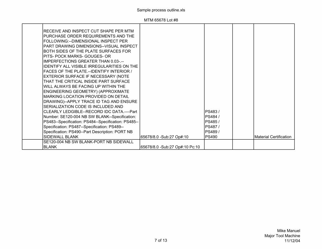
RECEIVE AND INSPECT CUT SHAPE PER MTM PURCHASE ORDER REQUIREMENTS AND THE FOLLOWING:--DIMENSIONAL INSPECT PER PART DRAWING DIMENSIONS--VISUAL INSPECT BOTH SIDES OF THE PLATE SURFACES FOR PITS- POCK MARKS- GOUGES- OR IMPERFECTIONS GREATER THAN 0.03-.--IDENTIFY ALL VISIBLE IRREGULARITIES ON THE FACES OF THE PLATE.--IDENTIFY INTERIOR / EXTERIOR SURFACE IF NECESSARY (NOTE THAT THE CRITICAL INSIDE PART SURFACE WILL ALWAYS BE FACING UP WITHIN THE ENGINEERING GEOMETRY) (APPROXIMATE MARKING LOCATION PROVIDED ON DETAIL DRAWING)--APPLY TRACE ID TAG AND ENSURE SERIALIZATION CODE IS INCLUDED AND CLEARLY LEDGIBLE--RECORD IDC DATA.----Part Number: SE120-004 NB SW BLANK--Specification: PS483--Specification: PS484--Specification: PS485--Specification: PS487--Specification: PS489--Specification: PS490--Part Description: PORT NB SIDEWALL BLANK 65678/8.0 -Sub:27 Op#:10
PS483 / PS484 / PS485 / PS487 / PS489 / PS490 Material Certification
SE120-004 NB SW BLANK-PORT NB SIDEWALL BLANK 65678/8.0 -Sub:27 Op#:10 Pc:10
7 of 13
Mike ManuelMajor Tool Machine
11/12/04

Sample process outline.xls
MTM 65678 Lot #8
FORM SIDEWALLS PER DRAWING AND TO FIT THE PROFILE OF FIXTURE # MTMFX-3060 AS FOLLOWS:--WHEN THE FORMED PANEL IS -BEST FIT- TO THE FIXTURE THEIR MUST BE A MAXIMUM GAP OF 0.125- BETWEEN THE FIXTURE PROFILE AND PANEL SURFACE- AND THE EDGES OF THE PART MUST PROTRUDE BEYOND THE ADJACENT FIXTURE FACES AT LEAST 0.25-.--NOTE THAT THE SURFACE IDENTIFIED AS -INSIDE- IS TO BE THE CONCAVE OR INWARD SURFACE AFTER FORMING.--100% DIMENSIONAL VERIFICATION AND CERTIFICATE OF COMPLIANCE TO PURCHASE ORDER SPECIFICATIONS IS REQUIRED WITH SHIPMENT.--Specification: PS483 Rev: B--Part Number: SE120-004 NB SW--Part Description: PORT NB SIDEWALL--Dimensional Report: DIMENSIONAL REPORT--Certificate of Conformance: --Material Type: INCONEL 625--Material Thickness: 0.5---Specification: PS488 Rev: A 65678/8.0 -Sub:27 Op#:20
PS483 / PS488
Certificate of Conformance / Dimensional Report
RECEIVE AND INSPECT FORMED PANELS AS FOLLOWS:--DIMENSIONAL INSPECT PART TO FIXTURE BY VERIFYING PART TO FIXTURE GAP- AND EXCESS TRIM ALLOWANCE EXISTS WHERE NECESSARY.--AUDIT MATERIAL THICKNESS (KEY ON AREAS WHICH RECEIVED A HIGH DEGREE OF FORMING)--VISUAL INSPECT THE ENTIRE SURFACE FINISH--AUDIT SURFACE FINISH WITH GAGE--AUDIT MAGNETIC PERMEABILITY--RECORD IDC DATA--Part Number: SE120-004 NB SW--Part Description: PORT NB SIDEWALL--Specification: PS483--Specification: PS484--Specification: PS485--Specification: PS487 65678/8.0 -Sub:27 Op#:30
PS483 / PS484 / PS485 / PS487
8 of 13
Mike ManuelMajor Tool Machine
11/12/04
Sample process outline.xls
MTM 65678 Lot #8
RECEIVE AND INSPECT CUT SHAPE PER MTM PURCHASE ORDER REQUIREMENTS AND THE FOLLOWING:--DIMENSIONAL INSPECT PER PART DRAWING DIMENSIONS--VISUAL INSPECT BOTH SIDES OF THE PLATE SURFACES FOR PITS- POCK MARKS- GOUGES- OR IMPERFECTIONS GREATER THAN 0.03-.--IDENTIFY ALL VISIBLE IRREGULARITIES ON THE FACES OF THE PLATE.--APPLY TRACE ID TAG AND ENSURE SERIALIZATION CODE IS INCLUDED AND CLEARLY LEDGIBLE--RECORD IDC DATA.----Part Number: SE122-072-1BLANK--Specification: PS483--Specification: PS484--Specification: PS485--Specification: PS487--Specification: PS489--Specification: PS490 65678/8.0 -Sub:82 Op#:10
PS483 / PS484 / PS485 / PS487 / PS489 / PS490 Material Certification
SE122-072-1BLANK-PORT NB WELD FLANGE BLANK 65678/8.0 -Sub:82 Op#:10 Pc:10SETUP AND FACE ONE SIDE TO MINIMUM CLEANUP--N/C INNER AND OUTER PROFILE PER PROGRAM--INVERT AND FACE THE OTHER SIDE TO CLEANUP MAINTAINING A 1.400- MINIMUM FLANGE THICKNESS.--Part Number: SE122-072-1--Part Description: PORT NB WELD FLANGE--Specification: PS483 65678/8.0 -Sub:82 Op#:20 PS483DEBURR AND CLEANUP--Specification: PS483 65678/8.0 -Sub:82 Op#:30 PS483INSPECT AND RECORD IDC DATA.--NOTE THAT HOLES AND THICKNESS WILL BE FINISHED AFTER WELDING TO PORT SIDEWALLS--Part Number: SE122-072-1--Part Description: PORT NB WELD FLANGE--Specification: PS483--Specification: PS487 65678/8.0 -Sub:82 Op#:40
PS483 / PS487 / IDC:8
N/C PROGRAMMING FOR PARENT OPERATION SEQUENCE REQUIREMENTS 65678/8.0 -Sub:86 Op#:10N/C PROGRAMMING FOR PARENT OPERATION SEQUENCE REQUIREMENTS 65678/8.0 -Sub:93 Op#:10
9 of 13
Mike ManuelMajor Tool Machine
11/12/04

Sample process outline.xls
MTM 65678 Lot #8
RECEIVE AND INSPECT CUT SHAPE PER MTM PURCHASE ORDER REQUIREMENTS AND THE FOLLOWING:--DIMENSIONAL INSPECT PER PART DRAWING DIMENSIONS--VISUAL INSPECT BOTH SIDES OF THE PLATE SURFACES FOR PITS- POCK MARKS- GOUGES- OR IMPERFECTIONS GREATER THAN 0.03-.--IDENTIFY ALL VISIBLE IRREGULARITIES ON THE FACES OF THE PLATE.--APPLY TRACE ID TAG AND ENSURE SERIALIZATION CODE IS INCLUDED AND CLEARLY LEDGIBLE--RECORD IDC DATA.----Part Number: SE122-172-1BLANK--Specification: PS483--Specification: PS484--Specification: PS485--Specification: PS487--Specification: PS489--Specification: PS490--Part Description: PORT NB COVER BLANK 65678/8.0 -Sub:84 Op#:10
PS483 / PS484 / PS485 / PS487 / PS489 / PS490 Material Certification
SE122-172-1BLANK-PORT NB COVER BLANK 65678/8.0 -Sub:84 Op#:10 Pc:10SETUP AND FACE ONE SIDE TO CLEANUP--N/C PERIMETER TO FINISH PER DRAWING AND PROGRAM--DRILL AND REAM A CONSTRUCTION HOLE (0.2500- DIAMETER X 0.250- MAX DEEP) AT THE INTERSECTION OF DATUMS -A- & -B-.--INVERT- REPOSITION AND CLAMP.--FACE TO BRING IN THICKNESS PER DRAWING--N/C GROOVE PER DRAWING AND PROGRAM (NOTE FINISH REQUIREMENTS- PART WILL BE POLISHED TO A 16 MICRO-INCH SURFACE FINISH AFTER MACHINING)--DRILL AND TAP HOLES PER DRAWING AND PROGRAM--RECORD IDC DATA--Part Number: SE122-172-1--Part Description: PORT NB COVER PLATE--Specification: PS483 65678/8.0 -Sub:84 Op#:20 PS483 / IDC:3DEBURR AND CLEANUP--Specification: PS483 65678/8.0 -Sub:84 Op#:25 PS483WRAP THE PART WITH POLYETHYLENE FOAM AND SHEET AND PALLETIZE FOR DELIVERY TO SUBCONTRACT.--NOTE THAT THREE PARTS SHOULD SHIP TOGETHER ON ONE PALLET.--Specification: PS483 65678/8.0 -Sub:84 Op#:30 PS483
10 of 13
Mike ManuelMajor Tool Machine
11/12/04

Sample process outline.xls
MTM 65678 Lot #8POLISH THE BOTTOM OF THE GROOVE TO ACHIEVE 16 MICRO-INCH RA SURFACE FINISH--(REF. DRAWING SECTION VIEW A-A- ZONE C7)--DIMENSIONAL VERIFICATION RECORD AND CERTIFICATE OF CONFORMANCE REQUIRED WITH SHIPMENT--REFERENCE ROLLEIGH QUOTATION RQ-0281 DATED 09NOV04.--Part Number: SE122-172-1--Part Description: PORT NB COVER PLATE--Specification: PS483--Specification: PS488--Dimensional Report: --Certificate of Conformance: 65678/8.0 -Sub:84 Op#:40
PS483 / PS488
Certificate of Conformance / Dimensional Report
VISUAL INSPECT PART FOR HANDLING DAMAGE-ETC...--VERIFY SUBCONTRACTOR DOCUMENTATION--VERIFY FLATNESS HAS BEEN MAINTAINED--INSPECT GROOVE DIMENSIONAL FEATURES--INSPECT GROOVE SURFACE FINISH (SIDES AND BOTTOM)--AUDIT MAGNETIC PERMEABILITY--RECORD IDC DATA--Part Number: SE122-172-1--Part Description: PORT NB COVER PLATE--Specification: PS483--Specification: PS487 65678/8.0 -Sub:84 Op#:50
PS483 / PS487 / IDC:7
N/C PROGRAMMING FOR PARENT OPERATION SEQUENCE REQUIREMENTS 65678/8.0 -Sub:85 Op#:10RECEIVE AND INSPECT PER MTM PURCHASE ORDER REQUIREMENTS--NOTIFY DOUG MCCORKLE UPON RECIEPT--Certificate of Conformance: --Part Number: 190019--Part Description: BOLT KIT- MDC VACUUM--Specification: PS489 65678/8.0 -Sub:87 Op#:10 PS489
Certificate of Conformance / Material Certification
190019-BOLT KIT- MDC VACUUM PRODUCTS CORP. 65678/8.0 -Sub:87 Op#:10 Pc:10
11 of 13
Mike ManuelMajor Tool Machine
11/12/04

Sample process outline.xls
MTM 65678 Lot #8RECEIVE AND INSPECT CUT SHAPE PER MTM PURCHASE ORDER REQUIREMENTS AND THE FOLLOWING:--DIMENSIONAL INSPECT PER PART DRAWING DIMENSIONS--VISUAL INSPECT BOTH SIDES OF THE PLATE SURFACES FOR PITS- POCK MARKS- GOUGES- OR VISIBLE IMPERFECTIONS.--IDENTIFY ALL VISIBLE IRREGULARITIES ON THE FACES OF THE PLATE.--APPLY TRACE ID TAG AND ENSURE SERIALIZATION CODE IS INCLUDED AND CLEARLY LEDGIBLE--RECORD IDC DATA.----Part Number: SE122-173-1BLANK--Specification: PS483--Specification: PS484--Specification: PS485--Specification: PS487--Specification: PS489--Specification: PS490 65678/8.0 -Sub:88 Op#:10
PS483 / PS484 / PS485 / PS487 / PS489 / PS490 Material Certification
SE122-173-1BLANK-PORT NB SEAL RETAINER BLANK 65678/8.0 -Sub:88 Op#:10 Pc:10
SETUP ON FLAT SUB-PLATE--BOLT IN PLACE THROUGH PROVIDED HOLES--ALIGN AND CLAMP IN PLACE--N/C PERIMETER PROFILE PER DRAWING AND PROGRAM--N/C FACE MILL TO THICKNESS PER DRAWING AND PROGRAM--DRILL THROUGH HOLES PER DRAWING (WILL C'BORE IN NEXT SETUP)--REMOVE AND SETUP INTO SUPPORT FIXTURE (SUPPORTING THE OUTSIDE PROFILE)--ALIGN AND CLAMP IN PLACE (THROUGH PART HOLES- AND TOE CLAMP FROM THE OUTSIDE AS NECESSARY).--ROUGH N/C TO REMOVE INNER DROP MATERIAL--FINISH N/C THE INNER PROFILE PER DRAWING AND PROGRAM--COUNTERBORE THE HOLES PER DRAWING AND PROGRAM--Specification: PS483--Part Number: SE122-173-1--Part Description: PORT NB SEAL RETAINER 65678/8.0 -Sub:88 Op#:20 PS483 / IDC:15
12 of 13
Mike ManuelMajor Tool Machine
11/12/04

Sample process outline.xls
MTM 65678 Lot #8
INSPECTION (ON MACHINE) IN RESTRAINED CONDITION--VERIFY PREVIOUS SEQUENCE IDCs--INSPECT MAGNETIC PERMEABILITY AND RECORD IDC DATA--Part Number: SE122-173-1--Part Description: PORT NB SEAL RETAINER--Specification: PS483--Specification: PS484 65678/8.0 -Sub:88 Op#:30
PS483 / PS484
DEBURR AND CLEANUP--Specification: PS483 65678/8.0 -Sub:88 Op#:40 PS483N/C PROGRAMMING FOR PARENT OPERATION SEQUENCE REQUIREMENTS 65678/8.0 -Sub:92 Op#:10RECEIVE AND VISUAL INSPECT CUSTOMER SUPPLIED MATERIAL PER MTM PURCHASE ORDER REQUIREMENTS--NOTIFY DOUG MCCORKLE UPON RECIEPT--Certificate of Conformance: --Part Number: SE120-004-52--Part Description: O-RING- METAL- HELICOFLEX--Specification: PS489--Material Certification: 65678/8.0 -Sub:89 Op#:10 PS489
Certificate of Conformance / Material Certification
SE120-004-52-O-RING- METAL- HELICOFLEX TYPE HNV 65678/8.0 -Sub:89 Op#:10 Pc:10RECEIVE AND VISUAL INSPECT CUSTOMER SUPPLIED MATERIAL PER MTM PURCHASE ORDER REQUIREMENTS--NOTIFY DOUG MCCORKLE UPON RECIEPT--Certificate of Conformance: --Part Number: SE120-004-52--Part Description: O-RING- METAL- HELICOFLEX--Specification: PS489--Material Certification: 65678/8.0 -Sub:90 Op#:10 PS489
Certificate of Conformance / Material Certification
SE120-004-53-O-RING- METAL- HELICOFLEX TYPE HNV 65678/8.0 -Sub:90 Op#:10 Pc:10
RECEIVE AND VISUAL INSPECT PER MTM PURCHASE ORDER REQUIREMENTS--Part Number: SE120-004-47--Part Description: NB SEAL RETAINER SCREWS--Certificate of Conformance: 65678/8.0 -Sub:91 Op#:10
Certificate of Conformance
98164A133-BHCS 316SST #8-32UNC-3A X 0.25- LONG 65678/8.0 -Sub:91 Op#:10 Pc:10
13 of 13
Mike ManuelMajor Tool Machine
11/12/04

PS-484
Process Specification – Magnetic Permeability Inspection 65678 PPPL NCSX Vacuum Vessel Sub Assembly
Doc: PS484 Rev. C Page 1 of 3 Prepared by: Doug McCorkle Date: 27Oct04 Status: Approved for Submittal
1. PURPOSE This specification establishes the process parameters to ensure magnetic permeability testing performed on the NCSX SE120-002 Vacuum Vessel Sub Assembly is maintained within the guidelines required by PPPL product specification NCSX-CSPEC-121-02
2. SCOPE
This specification defines the minimum requirements for measuring magnetic permeability of materials used to produce the NCSX VVSA components (using a Severn Engineering High Sensitivity Low-Mu Permeability Indicator) when required by the MTM MIT.
3. DEFINITIONS
PPPL – Princeton Plasma Physics Laboratory MTM – Major Tool & Machine, Inc. NCSX – National Compact Stellarator Experiment VVSA- Vacuum Vessel Sub Assembly MIT – Manufacturing, Inspection, and Test plan (MTM Mfg. Routing) IDC – MTM Inspection Data Checklist system QAP – MTM Quality Assurance Planning system NCR – Non-Conformance Report
4. REFERENCE DOCUMENTS
PPPL Product Specification NCSX-CSPEC-121-02 ASTM A800/A800M – Standard Practice for Estimating Ferrite Content Operating manual – High Sensitivity Low-Mu Permeability Indicator – Severn Engineering QA-SOP-01 Non-Conformance Control MTM Mfg. Routing / Inspection Plan / Quality Assurance Plan 65678 PS483 – Cleanliness Control
5. EQUIPMENT AND SUPPLIES
• High Sensitivity Low-Mu Permeability Indicator – Severn Engineering 6. GENERAL INFORMATION / PRECAUTIONS (obtained from Severn Engineering website)
The operation of the Indicator is based on the mutual attraction of a permanent bar magnet for a known standard and an unknown material. In use, an insert is screwed into the top of the case. The magnet is then attracted to the insert by a force dependent upon the insert's permeability. The end of the magnet projecting from the opening in the bottom of the case is then brought into contact with the material being tested. It is essential that the contact surface be clean and free from oxide scale or foreign material. The Indicator is then moved away in a direction normal to the contact surface. If the material being tested has a permeability higher than that of the insert value, the magnet will first break contact with the insert as the Indicator is moved away. Only full, complete breaks should be considered as indicative of a higher permeability than the test material. On the other hand, if the permeability of the material being tested is lower than that of the insert value, the magnet will first break contact with the test material as the Indicator is moved away. Thus, by interchanging the inserts, it is possible to bracket the permeability of the materials under test.

PS-484
Process Specification – Magnetic Permeability Inspection 65678 PPPL NCSX Vacuum Vessel Sub Assembly
Doc: PS484 Rev. C Page 2 of 3 Prepared by: Doug McCorkle Date: 27Oct04 Status: Approved for Submittal
Two features of the Indicator deserve special mention. First, the balanced beam to which the magnet is attached permits the use of the Indicator in all positions without correction due to gravity. Secondly, the hemispherical magnet ends provide point contact with the inserts and the test materials. The High Sensitivity Low-Mu Permeability Indicator must be handled with care. The following precautions should be observed: • Remove metal filings, chips and dirt from the surface of the material under test. Filings and dirt on the
end of the magnet can be removed with masking tape. • Under no circumstances bring another magnet in contact with the indicator magnet. This will disturb
the calibration of the Indicator to such an extent that it will necessitate its return and subsequent recalibration.
• Be sure inserts are screwed firmly in place so as to establish contact with the magnet. • Do not jerk the Indicator away from the test material, especially with the 1.01 insert in place. This will
tend to give a false indication. Smoothly lift the unit straight up. Do not “rock” the unit while removing.
• Avoid as much as possible contacting the Indicator with strongly magnetic materials such as steel, cast iron, or straight chromium steels. This can be accomplished by first screening the materials under test with a hand magnet.
• Do not drop the Indicator • When not in use keep the Indicator in its box with the highest value insert in place in the Indicator. • Inserts are not interchangeable between indicators
7. INSTRUCTIONS
7.1. Ensure all locations where measurements will be taken are clean and free of any dirt, oil, lint, or any other foreign matter that may affect the readings taken.
7.1.1. If cleaning is necessary, it should be performed in compliance with PS483.
7.2. Ensure the part being checked is isolated from ferrous materials (e.g. work tables, bracing, tools, etc…). In addition, any part or material that is suspect of holding residual magnetism must be demagnetized before taking a permeability measurement. Residual magnetism can adversely effect permeability measurements.
7.3. If the panel / assembly has not already been laid out for inspection, layout according to the inspection
drawing. The layout should cover the entire part evenly, and consist of an approximate 6” grid throughout the body of the component, and an approximate 1” grid near weld seams and edges.
7.4. Inspect the magnetic permeability at each inspection point following the directions given within the
manufacturer’s operating manual, MTM MIT, above information, and the following:
7.4.1. Screw the insert reflecting the maximum allowable relative permeability into the top of the case. For example, if the area in question cannot exceed 1.2 mu, use the 1.2 mu indicator.
7.4.1.1. Use the following criteria for insert selection: • Overall relative magnetic permeability of Inconel 625 components: 1.02 max. • Overall relative magnetic permeability of 316SST components: 1.02 max. • Overall relative magnetic permeability in welds (and heat affected zones) joining 316 SST to
Inconel 625: 1.2 max. 7.4.2. Place the indicator on the piece under test with the exposed magnet making contact within the grid
cell.

PS-484
Process Specification – Magnetic Permeability Inspection 65678 PPPL NCSX Vacuum Vessel Sub Assembly
Doc: PS484 Rev. C Page 3 of 3 Prepared by: Doug McCorkle Date: 27Oct04 Status: Approved for Submittal
7.4.3. Smoothly lift the indicator away from the test surface, in a direction perpendicular to the test surface. 7.4.4. If the magnet breaks contact with the test piece before breaking contact with the indicator, the test
piece has a lower relative magnetic permeability and is acceptable. 7.4.5. If the magnet breaks contact with the indicator before breaking contact with the test piece, the test
piece has a higher relative magnetic permeability.
7.4.5.1. Recheck the area with successively higher value indicators until a determination can be made that the test piece permeability is greater than one indicator (indicator broke first), but less than another (test piece broke first).
7.5. If out-of-tolerance conditions are detected, additional measurements must be taken in the immediate area
to adequately define the extent of the non-conformance. Continue checking in all directions in a circular pattern until conforming material is found. The approximate size and location of the nonconformance will be mapped and/or identified on the inspection drawing. The completed map / drawing will be included as an attachment to the resulting NCR.
8. QUALITY ASSURANCE / DOCUMENTATION
8.1. The MTM MIT will specify all in-process and final inspection documentation requirements. All quality documentation will be compiled electronically utilizing MTM’s integrated IDC and QAP systems
8.1.1. At a minimum, the MTM MIT will require documentation for all contractual features and/or physical
requirements (e.g. final component features / final material condition). 8.1.2. To ensure compliance is maintained throughout the manufacturing process, interim / additional
documentation requirements will be provided within the associated MTM IDC, and QAP system
8.1.3. When an IDC record, or QAP document is completed, reference to the specific area being tested will be clearly discernable. The record will include the following information (as applicable):
• MTM Work Order Number • Part Identification Number • Part Description • Part Serial Number • Date of Inspection • Gage Serial Number • Reference Standard Serial Number • Inspector Signature / Acknowledgement, Initials, or Stamp
8.1.4. For all MIT operation sequences that include this document as a task requisite, but do not specify
physical inspection records or documentation, the electronic completion (“clocking out”) of each sequential manufacturing operation within the MTM (Visual Manufacturing®) routing confirms compliance to the applicable requirements. The MTM employee completing the electronic transaction (which completes and closes the operation sequence) personally acknowledges completeness and compliance to the routing instructions.
8.2. All un-authorized exceptions / out of tolerance conditions according to MTM MIT will be documented
within the MTM Non-Conformance system per QA-SOP-01.

ID Task Name Contract Start Contract Finish Plan Start Plan Finish MileStones
%Complete
1 Submit Proposal Thu 7/22/04 Thu 7/22/04 Thu 7/22/04 Thu 7/22/04 100%
2 Teleconference to discuss Proposal Mon 7/26/04 Fri 7/30/04 Mon 7/26/04 Fri 7/30/04 100%
3 Receive Order Tue 8/31/04 Tue 8/31/04 Tue 8/31/04 Fri 9/24/04 100%
4 Start Up/Engineering LI#1 Thu 7/22/04 Mon 12/13/04 NA NA 20%
5 Process Order Tue 8/31/04 Mon 12/13/04 Fri 9/24/04 Thu 12/30/04 20%
6 Sect 5.1.3 Proc Outline & Asc Procedu Thu 7/22/04 Thu 7/22/04 Fri 9/24/04 Fri 12/10/04 95 10%
7 Special Tooling LI# 2 Thu 7/22/04 Fri 10/28/05 NA NA 1%
8 Dies Mon 9/6/04 Fri 10/28/05 NA NA 1%
9 Engineering Mon 9/6/04 Fri 10/22/04 Mon 9/20/04 Wed 12/1/04 5%
10 Sect 5.1 Segmentation Scheme Thu 10/27/05 Fri 10/28/05 Thu 11/4/04 Fri 11/19/04 75 0%
11 Procure Materials (4 sets) Mon 9/13/04 Fri 10/22/04 Mon 11/15/04 Fri 1/7/05 215 0%
12 Machine Complete Fri 10/8/04 Thu 12/2/04 Wed 12/1/04 Fri 1/28/05 0%
13 Deburr Thu 12/2/04 Tue 12/7/04 Fri 12/10/04 Fri 2/4/05 0%
14 Inspection Wed 12/8/04 Mon 12/20/04 Fri 12/17/04 Fri 2/11/05 239 0%
15 Fixtures (2) 60 degree Mon 9/6/04 Tue 12/7/04 NA NA 1%
16 Engineering Mon 9/6/04 Fri 11/5/04 Mon 10/25/04 Fri 12/17/04 2%
17 Procure Materials Mon 9/13/04 Fri 10/8/04 Fri 12/17/04 Fri 1/14/05 0%
18 Machine Complete Mon 10/11/04 Fri 11/19/04 Fri 1/14/05 Fri 2/4/05 0%
19 Assemble Mon 11/22/04 Fri 11/26/04 Fri 2/4/05 Mon 2/14/05 0%
20 Deburr Fri 11/26/04 Tue 11/30/04 Mon 2/14/05 Wed 2/16/05 0%
21 Inspection Wed 12/1/04 Tue 12/7/04 Wed 2/16/05 Fri 2/18/05 0%
22 Fixture (1) 120 degree Thu 7/22/04 Thu 7/22/04 NA NA 0%
23 Engineering Thu 7/22/04 Thu 7/22/04 Thu 1/6/05 Fri 1/21/05 1%
24 Procure Materials Thu 7/22/04 Thu 7/22/04 Fri 1/21/05 Fri 2/4/05 220 0%
25 Machine Complete Thu 7/22/04 Thu 7/22/04 Fri 2/4/05 Fri 2/18/05 0%
26 Assemble Thu 7/22/04 Thu 7/22/04 Fri 2/18/05 Tue 2/22/05 0%
27 Deburr Thu 7/22/04 Thu 7/22/04 Tue 2/22/05 Fri 2/25/05 0%
28 Inspection Thu 7/22/04 Thu 7/22/04 Fri 2/25/05 Fri 3/4/05 0%
29 Sect 5.1.2 Fiducials Thu 7/22/04 Thu 7/22/04 Mon 11/29/04 Fri 12/17/04 55 60%
30 Procure Vessel Material Thu 7/22/04 Thu 7/22/04 Fri 10/29/04 Fri 2/25/05 290 5%
31 Development Panels (9 panels) Fri 10/28/05 Fri 10/28/05 Fri 2/25/05 Tue 4/26/05 260 0%
32 Production Panels (9-18 panels) Fri 10/28/05 Fri 10/28/05 Tue 4/26/05 Tue 5/17/05 200 0%
33 Production Panels (36-45 panels) Fri 10/28/05 Fri 10/28/05 Tue 5/17/05 Tue 6/28/05 200 0%
34 First 120 deg seg LI #3 Thu 1/20/05 Mon 9/5/05 NA NA 0%
35 1st 60 deg segment Thu 1/20/05 Thu 4/21/05 Tue 3/29/05 Tue 5/10/05 0%
7/22
Teleconference to discuss Proposal
Receive Order
Start Up/Engineering LI#1
Process Order
Sect 5.1.3 Proc Outline & Asc Procedures
Special Tooling LI# 2
Dies
Engineering
Sect 5.1 Segmentation Scheme
Procure Materials (4 sets)
Machine Complete
Deburr
Inspection
Fixtures (2) 60 degree
Engineering
Procure Materials
Machine Complete
Assemble
Deburr
Inspection
Engineering
Procure Materials
Machine Complete
Assemble
Deburr
Inspection
Sect 5.1.2 Fiducials
Procure Vessel Material
Development Panels (9 panels)
Production Panels (9-18 panels)
Production Panels (36-45 panels)
First 120 deg seg LI #3
1st 60 deg segment
27 4 111825 1 8 152229 5 121926 3 10172431 7 142128 5 121926 2 9 162330 6 132027 6 132027 3 101724 1 8 152229 5 121926 3 10172431 7 142128 4 111825 2 9 162330 6 132027 4 111825 1 8 152229 5 121926Jul '04 Aug '04 Sep '04 Oct '04 Nov '04 Dec '04 Jan '05 Feb '05 Mar '05 Apr '05 May '05 Jun '05 Jul '05 Aug '05 Sep '05 Oct '05 Nov '05 Dec '05 Jan '06 Feb '06
Summary Proposal Milestone Planned Completed
NCSX VVSA for PPPLSubcontract S005243-F
MTM WO# 65678
Page 1 of 2 Mike Manuel11-09-04

ID Task Name Contract Start Contract Finish Plan Start Plan Finish MileStones
%Complete
36 2nd 60 deg segment Mon 2/28/05 Thu 4/21/05 Tue 5/3/05 Fri 6/3/05 0%
37 Join two pieces Thu 4/21/05 Thu 5/19/05 Sun 5/22/05 Tue 6/14/05 350 0%
38 Machine for Ports Thu 5/19/05 Wed 6/8/05 Tue 6/14/05 Tue 7/5/05 0%
39 Weld Ports Wed 6/8/05 Wed 6/29/05 Tue 7/5/05 Tue 8/16/05 0%
40 Final Machine Wed 6/29/05 Fri 7/22/05 Tue 8/16/05 Tue 9/6/05 0%
41 Vacuum Test Fri 7/22/05 Fri 8/5/05 Tue 9/6/05 Tue 9/20/05 0%
42 Cut Off Ports Fri 8/5/05 Fri 8/26/05 Tue 9/20/05 Tue 10/11/05 0%
43 Pack for Shipping LI#4 Fri 8/26/05 Thu 9/1/05 Tue 10/11/05 Fri 10/14/05 0%
44 Receive at PPPL Thu 9/1/05 Mon 9/5/05 Fri 10/14/05 Wed 10/19/05 375.56 0%
45 Second 120 deg seg LI# 3 Thu 4/21/05 Tue 9/20/05 NA NA 0%
46 60 deg segment Thu 4/21/05 Thu 6/9/05 Fri 6/3/05 Fri 7/1/05 0%
47 60 deg segment Thu 4/21/05 Thu 6/9/05 Tue 6/14/05 Tue 7/12/05 0%
48 Join two pieces Thu 6/9/05 Mon 6/27/05 Tue 7/5/05 Tue 7/19/05 350 0%
49 Machine for Ports Mon 6/27/05 Mon 7/11/05 Tue 7/19/05 Tue 8/9/05 0%
50 Weld Ports Mon 7/11/05 Wed 8/3/05 Tue 8/9/05 Tue 9/6/05 0%
51 Final Machine Wed 8/3/05 Fri 8/19/05 Tue 9/6/05 Tue 9/27/05 0%
52 Vacuum Test Fri 8/19/05 Fri 8/26/05 Tue 9/27/05 Tue 10/11/05 0%
53 Cut Off Ports Fri 8/26/05 Tue 9/13/05 Fri 10/7/05 Fri 10/21/05 0%
54 Pack for Shipping LI#4 Tue 9/13/05 Fri 9/16/05 Fri 10/21/05 Thu 10/27/05 0%
55 Receive at PPPL Fri 9/16/05 Tue 9/20/05 Thu 10/27/05 Mon 10/31/05 375 0%
56 Third 120 deg seg LI# 3 Thu 6/9/05 Fri 10/28/05 NA NA 0%
57 60 deg segment Thu 6/9/05 Thu 7/28/05 Fri 7/1/05 Fri 7/29/05 0%
58 60 deg segment Thu 6/9/05 Thu 7/28/05 Sun 7/17/05 Sun 8/14/05 0%
59 Join two pieces Thu 7/28/05 Thu 8/11/05 Tue 8/9/05 Tue 8/23/05 375 0%
60 Machine for Ports Thu 8/11/05 Tue 8/23/05 Tue 8/23/05 Tue 9/6/05 0%
61 Weld Ports Tue 8/23/05 Tue 9/13/05 Tue 9/6/05 Tue 9/27/05 0%
62 Final Machine Tue 9/13/05 Tue 9/27/05 Tue 9/27/05 Tue 10/11/05 0%
63 Vacuum Test Tue 9/27/05 Tue 10/4/05 Tue 10/11/05 Tue 10/25/05 0%
64 Cut Off Ports Tue 10/4/05 Tue 10/18/05 Tue 10/25/05 Tue 11/15/05 0%
65 Pack for Shipping LI#4 Tue 10/18/05 Fri 10/21/05 Tue 11/15/05 Fri 11/18/05 0%
66 Receive at PPPL Fri 10/21/05 Tue 10/25/05 Fri 11/18/05 Tue 11/22/05 375 0%
67 Pack for PPPL Tooling Fri 10/28/05 Fri 10/28/05 Fri 11/18/05 Fri 11/25/05 0%
68 Receive at PPPL Tooling Fri 10/28/05 Fri 10/28/05 Mon 11/28/05 Thu 12/1/05 486 0%
2nd 60 deg segment
Join two pieces
Machine for Ports
Weld Ports
Final Machine
Vacuum Test
Cut Off Ports
Pack for Shipping LI#4
Receive at PPPL
Second 120 deg seg LI# 3
60 deg segment
60 deg segment
Join two pieces
Machine for Ports
Weld Ports
Final Machine
Vacuum Test
Cut Off Ports
Pack for Shipping LI#4
Receive at PPPLReceive at PPPL
Third 120 deg seg LI# 3
60 deg segment
60 deg segment
Join two pieces
Machine for Ports
Weld Ports
Final Machine
Vacuum Test
Cut Off Ports
Pack for Shipping LI#4
Receive at PPPLReceive at PPPL
Pack for PPPL Tooling
Receive at PPPL Tooling
27 4 111825 1 8 152229 5 121926 3 10172431 7 142128 5 121926 2 9 162330 6 132027 6 132027 3 101724 1 8 152229 5 121926 3 10172431 7 142128 4 111825 2 9 162330 6 132027 4 111825 1 8 152229 5 121926Jul '04 Aug '04 Sep '04 Oct '04 Nov '04 Dec '04 Jan '05 Feb '05 Mar '05 Apr '05 May '05 Jun '05 Jul '05 Aug '05 Sep '05 Oct '05 Nov '05 Dec '05 Jan '06 Feb '06
Summary Proposal Milestone Planned Completed
NCSX VVSA for PPPLSubcontract S005243-F
MTM WO# 65678
Page 2 of 2 Mike Manuel11-09-04


![[XLS]Job Statistical Report · Web viewOwner's Phone # Job # Doc # Borough House # Street Name Block Lot Bin # Job Type Job Status Job Status Descrp Latest Action Date Building Type](https://img.dokumen.tips/doc/110x75/5af6a6d57f8b9ae9488f103d/xlsjob-statistical-viewowners-phone-job-doc-borough-house-street-name.jpg)