Embed Size (px)
Citation preview

� � � � � � � � � � � � � �
� � � � � � � � � � � � � � � � �� � � � � � � �� � � � ! � " � # � �

Copyright 2012Agilent, Inc.
Vacuum PumpIsolation (VPI) Valve
Dust-Off is a registered trademark of Falcon Safety Products, Inc.Krytox is a registered trademarks of DuPont.TriScroll is a trademark of Agilent, Inc.Viton is a registered trademark of DuPont Dow Elastomers.Apiezon L is a registered trademark of M & I Materials.
$
% � " " � & ' � � � � � � � � � � � � � � � � � � � � � � � � � � � � � � � � � � � � � � � � � � � � � � � � � � � � � � � � � � � � � � � � � � � � � � � � � � � � � � � � � � � � � � � � � � � � � � � � � � � � � � � � � � � � � � � � � � � � � � � � � � � � � � � � � � � � � � � � � � � � �% � " " � & ' � � ( � � � � � & � ) * ) + � � & � & � � � � � � � � � � � � � � � � � � � � � � � � � � � � � � � � � � � � � � � � � � � � � � � � � � � � � � � � � � � � � � � � � � � � � � � � � � � � � � � � � � � � � � �, � - � " ) � ) . � / � & ' 0 / � " � & � � � � � � � � � � � � � � � � � � � � � � � � � � � � � � � � � � � � � � � � � � � � � � � � � � � � � � � � � � � � � � � � � � � � � � � � � � � � � � � � � � � � � � � � � � � � � � � � � � � � � #1 � & � � & � 2 * 2 � � � & � � � � � � � � � � � � � � � � � � � � � � � � � � � � � � � � � � � � � � � � � � � � � � � � � � � � � � � � � � � � � � � � � � � � � � � � � � � � � � � � � � � � � � � � � � � � � � � � � � � � � � � � � � � � � � � � � � � � � � � �. � � & � � � � 0 & " � ) � � & � � � � � � � � � � � � � � � � � � � � � � � � � � � � � � � � � � � � � � � � � � � � � � � � � � � � � � � � � � � � � � � � � � � � � � � � � � � � � � � � � � � � � � � � � � � � � � � � � � � � � � � � � � � � � � � � � � � � � � � � 3� � � � � � � " � ( & � � � � � � � � � � � � � � � � � � � � � � � � � � � � � � � � � � � � � � � � � � � � � � � � � � � � � � � � � � � � � � � � � � � � � � � � � � � � � � � � � � � � � � � � � � � � � � � � � � � � � � � � � � � � � � � � � � � � � � � � � � � � � � 3� � � 4 ( � " � & � 2 5 " � � � ( � � � � � � � � � � � � � � � � � � � � � � � � � � � � � � � � � � � � � � � � � � � � � � � � � � � � � � � � � � � � � � � � � � � � � � � � � � � � � � � � � � � � � � � � � � � � � � � � � � � � � � � � � � � � � � � � � � 3� � 3 4 ( � " � & � � . � 6 � � � � � � � � � � � � � � � � � � � � � � � � � � � � � � � � � � � � � � � � � � � � � � � � � � � � � � � � � � � � � � � � � � � � � � � � � � � � � � � � � � � � � � � � � � � � � � � � � � � � � � � � � � � � � � � � � � 7� � 7 8 � � 9 � � � � . ( � � � / � � � & � � � � � � � � � � � � � � � � � � � � � � � � � � � � � � � � � � � � � � � � � � � � � � � � � � � � � � � � � � � � � � � � � � � � � � � � � � � � � � � � � � � � � � � � � � � � � � � � � � � � � � � � � � � �. � � & � � � � 0 � & � � � � & � � � � � � � � � � � � � � � � � � � � � � � � � � � � � � � � � � � � � � � � � � � � � � � � � � � � � � � � � � � � � � � � � � � � � � � � � � � � � � � � � � � � � � � � � � � � � � � � � � � � � � � � � � � � � � � � � � � � � � � � � � �� � � : � � � & " � � � � � � � � � � � � � � � � � � � � � � � � � � � � � � � � � � � � � � � � � � � � � � � � � � � � � � � � � � � � � � � � � � � � � � � � � � � � � � � � � � � � � � � � � � � � � � � � � � � � � � � � � � � � � � � � � � � � � � � � � � � � � � � � � � � �� � � 0 � & � � � � 2 ; 5 0 ; � � � � & � * 2 � � � & 8 " � . � " � � � < ; � � � � 5 � ( � � � � � � � � � � � � � � � � � � � � � � � � � � � � � � � � � � � � � � � � � � � � � � � � � � � � � � =� � � � � 8 " � . � " � � � 3 # # > 3 � # > � # # > � ) � � # � � � � � � � � � � � � � � � � � � � � � � � � � � � � � � � � � � � � � � � � � � � � � � � � � � � � � � � � � � � � � � � � � � � � � � � � � � � � � � � � � � � =� � � � � % � " � 2 � � � � � � � � � � � � � � � � � � � � � � � � � � � � � � � � � � � � � � � � � � � � � � � � � � � � � � � � � � � � � � � � � � � � � � � � � � � � � � � � � � � � � � � � � � � � � � � � � � � � � � � � � � � � � � � � � � � � � � � � � � � � =� � � � 3 8 " � . � " � � � 3 # # > � # # 0 � � " & � " � � � � � � � � � � � � � � � � � � � � � � � � � � � � � � � � � � � � � � � � � � � � � � � � � � � � � � � � � � � � � � � � � � � � � � � � � � � � � � � � � � � � � � � � � � � � � #� � 3 � � � 9 � � � � � � � � � � � � � � � � � � � � � � � � � � � � � � � � � � � � � � � � � � � � � � � � � � � � � � � � � � � � � � � � � � � � � � � � � � � � � � � � � � � � � � � � � � � � � � � � � � � � � � � � � � � � � � � � � � � � � � � � � � � � � � � � � � �. � � & � � 3 � . � " � � � � � � � � � � � � � � � � � � � � � � � � � � � � � � � � � � � � � � � � � � � � � � � � � � � � � � � � � � � � � � � � � � � � � � � � � � � � � � � � � � � � � � � � � � � � � � � � � � � � � � � � � � � � � � � � � � � � � � � � � � � � � � � � � 33 � � � � � � � � � ! � ' � � � � � � � � � � � � � � � � � � � � � � � � � � � � � � � � � � � � � � � � � � � � � � � � � � � � � � � � � � � � � � � � � � � � � � � � � � � � � � � � � � � � � � � � � � � � � � � � � � � � � � � � � � � � � � � � � � � � � � � � � � 33 � � � � ( � � " � / . � ! ? * � � � ! � � � � � � � � � � � � � � � � � � � � � � � � � � � � � � � � � � � � � � � � � � � � � � � � � � � � � � � � � � � � � � � � � � � � � � � � � � � � � � � � � � � � � � � � � � � � � � � � � � � � � � � � � 73 � � � � 5 � � & � @ � � � ( 9 " � 2 . � ! ? * � � � ! � ' � � � � � � � � � � � � � � � � � � � � � � � � � � � � � � � � � � � � � � � � � � � � � � � � � � � � � � � � � � � � � � � � � � � � � � � � � � � � � � � � � 73 � � � � � � � � 5 � � � � 4 ? " � 2 � � ( � � � � � & � � � � � � � � � � � � � � � � � � � � � � � � � � � � � � � � � � � � � � � � � � � � � � � � � � � � � � � � � � � � � � � � � � � � � � � � � � � � � � � � � � � A3 � 3 � � � � � � ! � ' � � � � � � � � � � � � � � � � � � � � � � � � � � � � � � � � � � � � � � � � � � � � � � � � � � � � � � � � � � � � � � � � � � � � � � � � � � � � � � � � � � � � � � � � � � � � � � � � � � � � � � � � � � � � � � � � � � � � � � � � � � � �3 � 7 8 " � � ! � � � 9 � � & � 2 � � � � � � � � � � � � � � � � � � � � � � � � � � � � � � � � � � � � � � � � � � � � � � � � � � � � � � � � � � � � � � � � � � � � � � � � � � � � � � � � � � � � � � � � � � � � � � � � � � � � � � � � � � � � � � � � � � � � � �3 � 7 � � ; 5 0 ; � � � � 1 � � & B � 5 � ( � ) � � C & � , � 2 9 ; � � � � � � � � � � � � � � � � � � � � � � � � � � � � � � � � � � � � � � � � � � � � � � � � � � � � � �3 � 7 � � ; 5 0 ; � � � � D � � E � � 1 � � � � ) 5 � � � & � � � � � � � � � � � � � � � � � � � � � � � � � � � � � � � � � � � � � � � � � � � � � � � � � � � � � � � � � � � � � � � � � � � � � � � � � � � � � � � � �3 � 7 � 3 ; 5 0 ; � � � � 1 � � � � � 8 � � . � � C � ' � � � � � � � � � � � � � � � � � � � � � � � � � � � � � � � � � � � � � � � � � � � � � � � � � � � � � � � � � � � � � � � � � � � � � � � � � � � � � � � � � � � � � � � � =3 � 7 � 7 ; 5 0 ; � � � � 4 ( � � 8 � � . � � C � ' � " � � & 1 � ( � � & � � ' � � � � � � � � � � � � � � � � � � � � � � � � � � � � � � � � � � � � � � � � � � � � � � � � � � � � � � � � � � =3 � 7 � A ; 5 0 ; � � � � � � � � � & � 4 ( � � � � � � � � � � � � � � � � � � � � � � � � � � � � � � � � � � � � � � � � � � � � � � � � � � � � � � � � � � � � � � � � � � � � � � � � � � � � � � � � � � � � � � � � � � � � � � � � � =3 � 7 � � 1 � � � � 2 1 � � � � � D � " 2 � B � " � & � / * � " � & � . ' � & � � � � � � � � � � � � � � � � � � � � � � � � � � � � � � � � � � � � � � � � � � � � � � � � � � � � � � � � � � � � � =3 � 7 � � . � � � � � ) ; � � � � � � , � & � � � � � � � � � � � � � � � � � � � � � � � � � � � � � � � � � � � � � � � � � � � � � � � � � � � � � � � � � � � � � � � � � � � � � � � � � � � � � � � � � � � � � � � � � � � � � � � � � � � � �3 � A � � � & � " ' � � ( � � " � � � � � � � � � � � � � � � � � � � � � � � � � � � � � � � � � � � � � � � � � � � � � � � � � � � � � � � � � � � � � � � � � � � � � � � � � � � � � � � � � � � � � � � � � � � � � � � � � � � � � � � � � � � � � � � � � � � � � � 3 #3 � � � � ( � � � � � & 5 � " & � � � � � � � � � � � � � � � � � � � � � � � � � � � � � � � � � � � � � � � � � � � � � � � � � � � � � � � � � � � � � � � � � � � � � � � � � � � � � � � � � � � � � � � � � � � � � � � � � � � � � � � � � � � � � � � � 3 �

This page intentionally left blank.
F
� 4 ( � " � & � 2 . � 6 � � � � � � � � � � � � � � � � � � � � � � � � � � � � � � � � � � � � � � � � � � � � � � � � � � � � � � � � � � � � � � � � � � � � � � � � � � � � � � � � � � � � � � � � � � � � � � � � � � � � � � � � � � � � � � � � � 7� . � 2 � � 5 9 � � � � � & � " : � � � & " � � � � 1 � � � & � � � � � � � � � � � � � � � � � � � � � � � � � � � � � � � � � � � � � � � � � � � � � � � � � � � � � � � � � � � � � � � � � � � � � � � � � � � � � �3 8 9 " � � 5 9 � � � � � & � " : � � � & " � � � � 1 � � � & � � � � � � � � � � � � � � � � � � � � � � � � � � � � � � � � � � � � � � � � � � � � � � � � � � � � � � � � � � � � � � � � � � � � � � � � � � � � � � �7 ; 5 0 * ( ( � � � � & � � � 8 " � . � " � � � 3 # # > � # # 0 � � " & � " 5 � ( � � � � � � � � � � � � � � � � � � � � � � � � � � � � � � � � � � � � � � � � � � � � � � � � � � � � � � � � � � � � #A 0 � & � � � � & � � � � � 2 " � � � � � � � � � � � � � � � � � � � � � � � � � � � � � � � � � � � � � � � � � � � � � � � � � � � � � � � � � � � � � � � � � � � � � � � � � � � � � � � � � � � � � � � � � � � � � � � � � � � � � � � � � � � � � � � �� * � � � ! � ' ; � � C � ) � � ( � � � � � & 5 � " & � � � � � � � � � � � � � � � � � � � � � � � � � � � � � � � � � � � � � � � � � � � � � � � � � � � � � � � � � � � � � � � � � � � � � � � � � � � � � � � � 3� * � � � ! � ' ; � � C � ) � � ( � � � � � & 5 � " & � � � � � � � � � � � � � � � � � � � � � � � � � � � � � � � � � � � � � � � � � � � � � � � � � � � � � � � � � � � � � � � � � � � � � � � � � � � � � � � � �

G

H
� 8 � � 9 � � � � . ( � � � / � � � & � � � � � � � � � � � � � � � � � � � � � � � � � � � � � � � � � � � � � � � � � � � � � � � � � � � � � � � � � � � � � � � � � � � � � � � � � � � � � � � � � � � � � � � � � � � � � � � � � � � � � � � � � �� 4 ( � " � & � 2 ; � � & � 2 � � � � � � � � � � � � � � � � � � � � � � � � � � � � � � � � � � � � � � � � � � � � � � � � � � � � � � � � � � � � � � � � � � � � � � � � � � � � � � � � � � � � � � � � � � � � � � � � � � � � � � � � � � � � � � � � �3 ; 5 0 ; � � � � 0 � & � � � � & � � � � & � � � � � � � � � � � � � � � � � � � � � � � � � � � � � � � � � � � � � � � � � � � � � � � � � � � � � � � � � � � � � � � � � � � � � � � � � � � � � � � � � � � � � � � � � � � � � � � � � � � =7 � � ( � � � � � & 5 � " & � @ I � & � � � � � � � � � � � � � � � � � � � � � � � � � � � � � � � � � � � � � � � � � � � � � � � � � � � � � � � � � � � � � � � � � � � � � � � � � � � � � � � � � � � � � � � � � � � � � � � � � � � � � � � 3 �

This page intentionally left blank.
J
Products manufactured by Seller are warranted against defects in materials and workmanship for twelve (12) months from date of shipment thereof to Customer, and Seller’s liability under valid warranty claims is limited, at the option of Seller, to repair, to replace, or refund of an equitable portion of the purchase price of the Product. Items expendable in normal use are not covered by this warranty. All warranty replacement or repair of parts shall be limited to equipment malfunctions which, in the sole opinion of Seller, are due or traceable to defects in original materials or workmanship. All obligations of Seller under this warranty shall cease in the event of abuse, accident, alteration, misuse, or neglect of the equipment. In-warranty repaired or replaced parts are warranted only for the remaining unexpired portion of the original warranty period applicable to the repaired or replaced parts. After expiration of the applicable warranty period, Customer shall be charged at the then current prices for parts, labor, and transportation.
Reasonable care must be used to avoid hazards. Seller expressly disclaims responsibility for loss or damage caused by use of its Products other than in accordance with proper operating procedures.
Except as stated herein, Seller makes no warranty, express or implied (either in fact or by operation of law), statutory or otherwise; and, except as stated herein, Seller shall have no liability under any war-ranty, express or implied (either in fact or by operation of law), statutory or otherwise. Statements made by any person, including representatives of Seller, which are inconsistent or in conflict with the terms of this warranty shall not be binding upon Seller unless reduced to writing and approved by an officer of Seller.
All claims under warranty must be made promptly after occurrence of circumstances giving rise thereto, and must be received within the applicable warranty period by Seller or its authorized representative. Such claims should include the Product serial number, the date of shipment, and a full description of the circumstances giving rise to the claim. Before any Products are returned for repair and/or adjust-ment, written authorization from Seller or its authorized representative for the return and instructions as to how and where these Products should be returned must be obtained. Any Product returned to Seller for examination shall be prepaid via the means of transportation indicated as acceptable by Seller. Seller reserves the right to reject any warranty claim not promptly reported and any warranty claim on any item that has been altered or has been returned by non-acceptable means of transportation. When any Product is returned for examination and inspection, or for any other reason, Customer shall be responsible for all damage resulting from improper packing or handling, and for loss in transit, notwith-standing any defect or non-conformity in the Product. In all cases, Seller has the sole responsibility for determining the cause and nature of failure, and Seller’s determination with regard thereto shall be final.
If it is found that Seller’s Product has been returned without cause and is still serviceable, Customer will be notified and the Product returned at its expense; in addition, a charge for testing and examination may be made on Products so returned.
3/1/00

K L
This manual uses the following standard safety protocols:M N O P Q P RThe warning messages are for attracting the attention of the operator to a particular procedure or practice which, if not followed correctly, could lead to serious injury.S N T U Q V PThe caution messages are displayed before procedures, which if not followed, could cause damage to the equipment.P V U WThe notes contain important information.
Operators and service personnel must be aware of all hazards associated with this equipment. They must know how to recognize hazardous and potentially hazardous conditions, and know how to avoid them. The consequences of unskilled, improper, or careless operation of the equipment can be serious. This product must only be operated and maintained by trained personnel. Every operator or service person must read and thoroughly understand operation/maintenance manuals and any additional information provided by Agilent, Inc. All warning and cautions should be read carefully and strictly observed. Consult local, state, and national agencies regarding specific requirements and regulations. Address any safety, operation, and/or maintenance questions to your nearest Agilent, Inc. office.
Cleanliness is vital when servicing any vacuum equipment. S N T U Q V PDo not use silicone oil or silicone grease.
Use powder-free butyl or polycarbonate gloves to prevent skin oils from getting on vacuum surfaces.
Do not clean any aluminum parts with Alconox®. Alconox is not compatible with aluminum and will cause damage.P V U WNormally, it is unnecessary to use vacuum grease. However, if it must be used, avoid silicone types, and use it sparingly. Apiezon® L grease is recommended (Agilent Part Number 695400004).

K K
When removing, checking or replacing O-rings, keep in mind the following:P V U WAgilent recommends replacing all O-rings during routine maintenance or during any maintenance procedure requiring that O-rings be removed.S N T U Q V PRemove O-rings carefully with your fingers. Do not use metal tools for this task. This prevents scratching of any sealing surfaces.
❑ Wipe all O-rings clean with a lint-free cloth before installation to ensure that no foreign matter is present to impair the seal.
❑ Do not use alcohol, methanol or other solvents on O-rings. To do so causes deterioration and reduces their ability to hold a vacuum.
❑ If applicable, apply a small amount of Apiezon® L grease and wipe the O-rings “shiny” dry.
In the United States, you can contact Agilent Customer Service at 1-800-882-7426. See the back cover of this manual for a listing of our sales and service offices.
Visit our web site at: http://www.chem.agilent.com/en-US/Products/Instruments/vacuum/pages/default.aspx.

This page intentionally left blank.
K $
The Vacuum Pump Isolation (VPI) valve is a safety valve that protects a vacuum system in the event of power failure by isolating the vacuum system and venting the mechanical pump. This avoids oil back up and allows the motor to restart the pump more easily. The VPI valve is offered with the ISO-KF flange sizes and solenoid voltages/frequencies most commonly found on mechanical pumps. Since it operates with atmospheric pressure and activates upon loss of electrical power, the novel design requires no external pressurized gas source.
The fast acting VPI valve is light weight, constructed of vacuum compatible materials, and maximizes pumping conductance. Lifetimes in excess of 100,000 cycles are typical, which translates into years of trouble free use in suitable environments. The opening burst is less than the critical backing pressure for turbomolecular and diffusion pumps, when appropriately sized mechanical pumps are used. The closing burst is minimized by the unique patented buffer volume design.
The VPI valve consumes little power. Installation is simple because standard ISO-KF dimensions are used, allowing the valve to replace elbows, tees, and crosses of the same size. Even when the mechanical pump is equipped with an integral anti-suckback valve, a VPI valve should be used because the pump’s integral valve will not vent it.
The VPI valve’s solenoid valve is connected in parallel with the mechanical pump’s electrical supply, either at its source or at the pump’s switch. When the electrical power is on, the solenoid valve is closed, allowing the pump to keep the VPI valve’s body and the vacuum system evacuated. Interruption of electrical power to the mechanical pump causes the solenoid valve to open. Air is admitted into the VPI valve causing it to close very quickly. This isolates the vacuum system from the mechanical pump, while the pressure differential between the outside atmosphere and the vacuum system provides the force to maintain the valve in its closed position without electrical or pneumatic power. With the vacuum system isolated, a series of small orifices admits air to the inlet port of the mechanical pump until it has risen to atmospheric pressure. When the mechanical pump is restarted, it evacuates the area above the piston until the pressure is lowered to approximately that of the vacuum system. The VPI valve automatically opens again allowing the vacuum system to be pumped at the full speed of the mechanical pump.
K X
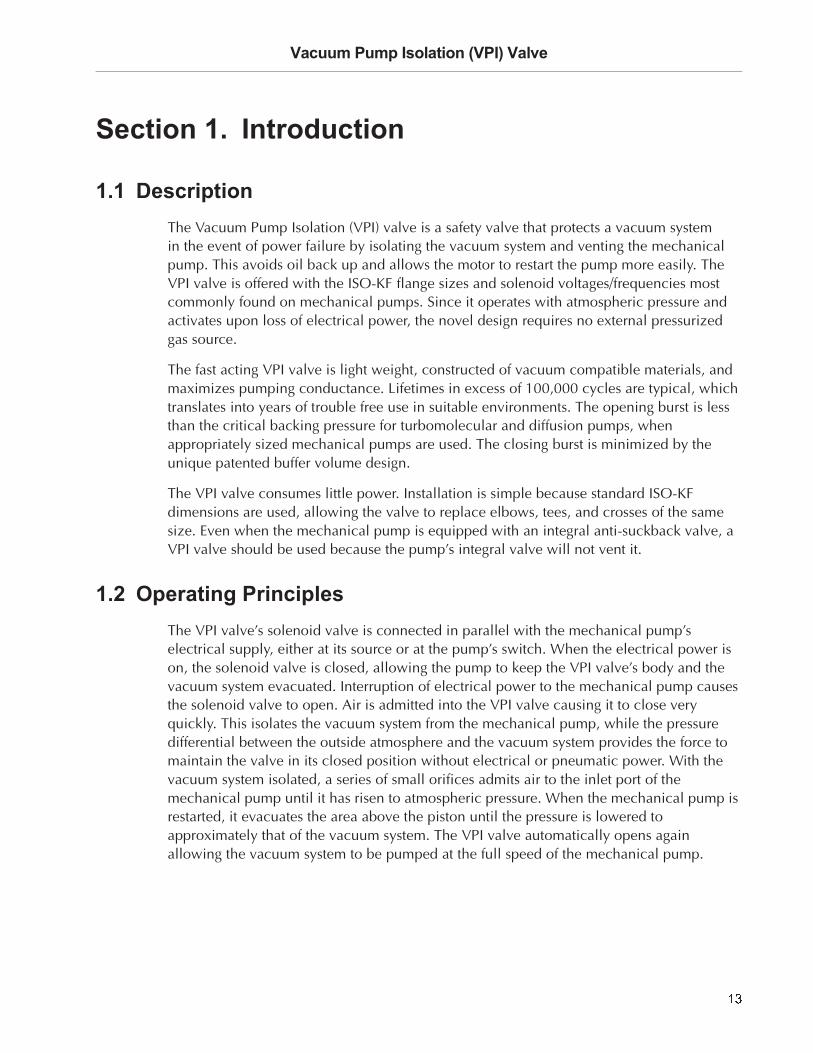
Y Z [ \ ] ^ _ ` a ^ ] b c Z d [ e ^ f \ ^ d g ^

K F
Figure 1 (a): Normal Operation – Open Position Power is on to the mechanical pump and the VPI valve. The mechanical pump, inlet side of the VPI valve, and the VPI valve are all under vacuum at approximately the same pressure. The spring is holding the VPI valve open, and the vacuum system is exposed to the mechanical pump’s full pumping speed.
Figure 1 (b): Power Interruption The VPI valve solenoid loses its power, since it is connected in parallel to the mechanical pump. The solenoid opens to the atmosphere. Air enters the VPI valve through the solenoid and creates a higher pressure above the piston than exists below it. The piston closes rapidly (30 ms). During this time only the inside of the piston (buffer volume) is being filled, isolating the vacuum system from any introduction of air. This figure shows the piston in transit downward.
Figure 1 (c): Valve Closed – Mechanical Pump Vented The piston is fully down and the VPI valve is fully closed. The higher pressure above the piston forces it against the valve seat, where the Viton® O-ring makes a vacuum tight seal. Air from the higher pressure area above the piston continues to flow through the small orifice in the top of the piston into the inside of the piston, and through a second small orifice in its side into the mechanical pump’s inlet port. This vents the mechanical pump to atmospheric pressure gradually. When the pump is fully vented, the pressure above the piston, inside the piston, and in the mechanical pump are the same (atmospheric). The pressure below the piston, in the vacuum system, is still lower and the piston remains down (closed), maintaining the vacuum system under vacuum. P V U W
Given enough time, the pressure in the vacuum system will rise due to outgassing, leaks, etc., or venting by the operator, and when the pressure is high enough, the spring will open the piston and the vacuum system will be at the same pressure as the mechanical pump (atmospheric).
Figure 1 (d): Power Restored The solenoid coil is energized causing the solenoid to close, isolating the inside of the VPI valve from the outside atmosphere. The mechanical pump evacuates the inside of the piston through the small orifice in its side and the area above the piston through the small orifice in the top of the piston via the inside of the piston. When the pressure above the piston is approximately equal to that in the vacuum system, the spring pushes the piston upward, fully opening the VPI valve. The vacuum system is now back in normal operation and exposed to the full pumping speed of the mechanical pump. P V U W
In Figure 1, the mechanical pump is connected to the port on the right side and the vacuum system to the bottom port.

K G
h b i j ^ _ h ^ g k d Z g b j e a ^ g Z l Z g b c Z m d no p q r s t u v p w x y z { r s | } F L q q ~� � t � � t � �❑ � p w x � K � K L � J t � q � � � � � � � �❑ � � t u � K � K L � J t � q � � � � � � � �� u p � r s � � r q � $ L q r u u r � � � p s w �� u p � r s � v � � � � K � K L � � � p � � � u r � � �� p � � � H | L � t � � � � p � � � t � � u r � t � r p s �F | � � t � � � � p � � � r � � � p u u r s � � � � � � � � q �t � � u r � t � r p s �� t � � � r t u �❑ � p w x t s w � u t s � � � � � � � � w � w t u � q r s � q } G L G K � � G ~❑
� r � � p s � t � � r s � w t u � q r s � q } { L { X ~❑ � � t u � } � � � r s � t s w w r t � � � t � q ~ � r � p s❑ � r w � � r s $ L X � � t r s u � � � � � � � u� � q � � � t � � � � � t s � � } � t u � � ~ L ¡ � p K L L ¡ �� � q � � � t � � � � � t s � � } � p u � s p r w ~ L ¡ � p F L ¡ �� � s � r s � � r q �❑
o � X L K L � �ι
p � � � s � � w � p u � q �❑
o � { F F L � �ι
p � � � s � � w � p u � q �

K H
The VPI Valve should be installed so that it is controlled by the vacuum pump’s electrical source, preferably at the vacuum pump’s automatic or manual switch. Ideally the opening of the valve should occur simultaneously with or after the pump start up. The valve closing should occur simultaneously or prior to the pump shut off.
Refer to Table 2 to verify that the solenoid operating voltage range of the VPI Valve to be installed is compatible with the actual operating voltage and frequency that will be used to control the VPI Valve. Verify that the valve is properly grounded prior to applying electrical power. P V U W
The VPI Valve can be damaged if it is energized with a voltage that is outside of it’s specified range.h b i j ^ ¢ ` a ^ ] b c Z d [ £ m j c b [ ^ nP M ¤ ¥¦ § Q ¦ ¨ © ª «§ ¨ ¬ P ® ¯ ° « ¬ P M ± ²¦ § Q ¦ ¨ © ª «§ ¨ ¬ P ® ¯ ° « ¬ ³ ´ © « µ ´ ¶ · V ¸ « ¬ ¨ ¶ µ ¹¦ ´ © ¨ ¹ « O ¨ µ ¹ « º ¨ » ¶ ¯ ® ¯V ¸ « ¬ ¨ ¶ µ ¹ S ® ¬ ¬ « µ � � y { F K { L F L G L � � y X L K { L F L G L J L � K $ { � � � F L � G L � ¼ G F q �� � y { F K $ $ F L G L � � y X L K $ $ F L G L K { L � K X G � � � F L � G L � ¼ { { q �� � y { F { { L F L G L � � y X L { { L F L G L K � L � { G X � � � F L � G L � ¼ $ { q �� � y { F { G G F L G L � � y X L { G G F L G L { $ J � { J $ � � � F L � G L � ¼ { $ q �� � y { F y o � { X z � � � y X L y o � { X z � { K | G � { G | X � z � { G H q �
K �
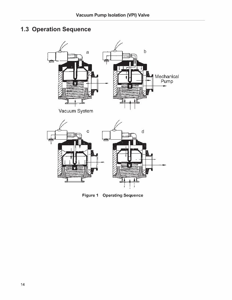
When installed correctly, the position of the VPI Valve is controlled by the TriScroll vacuum pump motor internal thermal switch and it’s electrical supply. The VPI Valve will open when the pump is running and close when it is stopped. It will also close if the TriScroll motor thermal overload protection switch shuts down the pump.P V U W
To prevent damage to the VPI Valve it must be installed only as specified below.
Refer to Table 3 to verify that the VPI Valve to be installed is compatible with the TriScroll Vacuum Pump supply voltage and frequency. Then, find the proper wiring diagram to use from Table 3. Remove the pump motor cover and connect the VPI Valve solenoid wire leads to the pump motor as shown in the diagram. Replace the pump motor cover, and verify that the valve is properly grounded prior to applying electrical power.h b i j ^ ½ £ ¾ ¿ £ b j À ^ ¿ d n c b j j b c Z m d Á b c bU ¬ ¶ ³  ¬ ´ © ©¦ ¨  ® ® ¯ § ® ¯ ¸V ¸ « ¬ ¨ ¶ µ ¹ ¦ ´ © ¨ ¹ « P M ¤ ¥¦ § Q ¦ ¨ © ª «§ ¨ ¬ P ® ¯ ° « ¬ P M ± ²¦ § Q ¦ ¨ © ª «§ ¨ ¬ P ® ¯ ° « ¬ ³ ´ © « µ ´ ¶ ·V ¸ « ¬ ¨ ¶ µ ¹¦ ´ © ¨ ¹ « O ¨ µ ¹ « M ¶ ¬ ¶ µ ¹ à ¶ ¨ ¹ ¬ ¨ ¯Ä ´  ¨ ¶ ´ µK L L � K { L � � �F L � G L � ¼K � � t � � � � y { F K { L F L G L � � y X L K { L F L G L J L � K $ { � � �F L � G L � ¼ Å r � � � � { p s � t � � K J� p � � p u � t � �{ L L � { $ L � � �F L � G L � ¼K � � t � � � � y { F K { L F L G L � � y X L K { L F L G L J L � K $ { � � �F L � G L � ¼ Æ Å r � � � � { p s � t � � K J� r � � � p u � t � �{ L L � � �F L � G L � ¼$ � � t � � � � y { F K { L F L G L � � y X L K { L F L G L J L � K $ { � � �F L � G L � ¼ Æ Å r � � � � $ p s � t � � K J� p � � p u � t � �{ $ L � � �F L � G L � ¼$ � � t � � � � y { F K $ $ F L G L � � y X L K $ $ F L G L K { L � K X G � � �F L � G L � ¼ Æ Å r � � � � $ p s � t � � K J� p � � p u � t � �$ � L � � �F L � G L � ¼$ � � t � � � � y { F { { L F L G L � � y X L { { L F L G L K � L � { G X � � �F L � G L � ¼ Æ Å r � � � � $ p s � t � � K J� r � � � p u � t � �

K J
Y Z [ \ ] ^ ¢ e Z d [ j ^ ¾ k b n ^ Ç m c m ] È j ^ g c ] Z g b j É m d d ^ g c Z m d n
Y Z [ \ ] ^ ½ h k ] ^ ^ ¾ k b n ^ Ç m c m ] È j ^ g c ] Z g b j É m d d ^ g c Z m d n
X K F � � �F L � G L � ¼$ � � t � � � � y { F { { L F L G L � � y X L { { L F L G L K � L � { G X � � �F L � G L � ¼ Æ Å r � � � � $ p s � t � � K J� r � � � p u � t � �X G L � F L � G L � ¼$ � � t � � � � y { F { G G F L G L � � y X L { G G F L G L { $ J � { J $ � � �F L � G L � ¼ Æ Å r � � � � $ p s � t � � K J� r � � � p u � t � �Ê Ë Ì Í Î Ï Ì Ð Ñ Ì Ò Î Ó Ô Õ Ð Ï Ö × Ì Í Õ Ô Ö Î Ø Ô Ó Î Í Ì Ù Î Ó Õ Ú Ô Ï Õ Ú Î Û Ó Ð Ë Ü Ó Ì Í Í × Ô Ü Ý Ý Þ Ò Ý Þ Ò Ì Ò Î Ó Ô Õ Ð Ï Ö × Ì Í Õ Ô Ö Î Ø Ð Ï Ì Ó Ñ Î Ó Õ Ì Ý Õ Ð Í Ð ß Î Õ Ú Î Û Ó Ð Ë Ü Ó Ì Í ÍÞ Ì Õ Ì Ó à Ø Ð Ï Õ Î Ó Ï Ô Í Õ Ú Î Ó Þ Ô Í Ø Ù Ð Õ Ü Ú Õ Ì Ô Ü Õ Ý Ô Õ Î Õ Ú Î á â ã á Ô Í × Î ä
h b i j ^ ½ £ ¾ ¿ £ b j À ^ ¿ d n c b j j b c Z m d Á b c b å É m d c Z d \ ^ æ çU ¬ ¶ ³  ¬ ´ © ©¦ ¨  ® ® ¯ § ® ¯ ¸V ¸ « ¬ ¨ ¶ µ ¹ ¦ ´ © ¨ ¹ « P M ¤ ¥¦ § Q ¦ ¨ © ª «§ ¨ ¬ P ® ¯ ° « ¬ P M ± ²¦ § Q ¦ ¨ © ª «§ ¨ ¬ P ® ¯ ° « ¬ ³ ´ © « µ ´ ¶ ·V ¸ « ¬ ¨ ¶ µ ¹¦ ´ © ¨ ¹ « O ¨ µ ¹ « M ¶ ¬ ¶ µ ¹ à ¶ ¨ ¹ ¬ ¨ ¯Ä ´  ¨ ¶ ´ µ
è é ê ë ì íî ë ï ð ñ ò ó ô õ ö ö ÷ø � ò ø é ù ì ÷è ú û è ï ë ü ìø ý ò ø é ù ì ÷
ø � þ ø ýõî ë ï ð ñ ò ó ô õ ö ö ÷ø � ò ø é ù ì ÷è ú û è ï ë ü ìø ý ò ø é ù ì ÷
ø � þ ø ýõ è é ê ë ì íî ë ÿ ì ò ó ô � ö ö ÷è ú û è ï ë ü ì� � � � � � � � � � � � � � � � �
è ú û è ï ë ü ìî ë ÿ ì ò ó ô � ö ö ÷ ì �î � ê � ù � � ï ù � ì� � é í ì � ì ë ë ê �î ë ÿ ì ø ý ò ø é ù ì ÷è ú û è ï ë ü ìø � ò ø é ù ì ÷ø õ ò ø é ù ì ÷� � � � � � � � � � � � � � � � � î � ê � ù
è ú û è ï ë ü ì � � ï ù � ì � ì ë ë ê � ì �è ú û è ï ë ü ìø ý ò ø é ù ì ÷� � é í ìø � ò ø é ù ì ÷î ë ÿ ìø õ ò ø é ù ì ÷è ú û è ï ë ü ì

{ L
For TriScroll 300/600 Inverter models (Figure 4), a 24 VDC VPI kit (VPI25INV24DC for triScroll 300/VPI40INV24DC for TriScroll 600), includes a VPI valve, a communication cable, a 24 VDC power supply, and a splitter cord. The VPI valve is controlled by an output signal from the inverter that is tied to motor operation.
Y Z [ \ ] ^ � £ ¾ ¿ � a a j Z g b c Z m d Z d h ] Z e g ] m j j ½ � � � � � � ¿ d À ^ ] c ^ ] ¾ \ � a nP V U WThe VPI valve kit provided must be connected to I/O P1 before starting the pump and operating the VPI valve. To prevent damage to the valve, it must be installed only as specified below.
¾ _É m � � \ d Z g b c Z m dÉ b i j ^ £ ¾ ¿ £ b j À ^
Ç b Z d n ¾ m � ^ ] ¿ d a \ ce a j Z c c ^ ] É m ] æ� � � !¾ m � ^ ] e \ a a j "

{ K
To install:
1. Connect the 24 VDC power supply and the pump inverter to the mains power using the splitter cord.
2. Connect the communication cable DB9 connector into the inverter I/O port (P1).
3. Connect the 24 VDC power supply output cord to the communications cable labeled 24 V.
4. Connect the VPI solenoid cord to the communications cable connector labeled VPI.

{ {
The VPI valve is installed between the mechanical pump and vacuum chamber or high vacuum pump (Figure 5). The flow arrows on the unit’s label point from the vacuum system to the mechanical pump.
Y Z [ \ ] ^ # ¿ d n c b j j b c Z m d Á Z b [ ] b �While it is preferable to mount it directly onto the mechanical pump, it may be located remotely. For best performance, the maximum volume should be on the vacuum system side, and the minimum volume on the mechanical pump side of the VPI valve. Operation is position independent and standard ISO-KF centering ring assemblies and clamps are used to connect the VPI valve. The valve body can operate in ambient temperatures up to 100° C, but the solenoid is limited to about 50° C because of the heat generated by the coil. This should be kept in mind when selecting a mounting location.
The body of the VPI valve is very rugged, and it is difficult to deform it in any normal piping arrangement used in vacuum systems. It is possible, however, that tremendous forces could result from thermal expansion or from a long run of pipe cantilevered from a fixed valve. Where this possibility exists, provide stress relief for the valve by installing a short bellows and support the attached piping other than with the valve.
Valves are shipped with plastic snap-on covers over the ports to protect the delicate seal surfaces and to keep the valve clean. These covers should be left in place until the moment when the valve is to be installed in the piping. A single fiber or bit of lint on an O-ring seal is enough to prevent leak-tight sealing. The usual cleaning techniques in vacuum practice should be observed in installing the valve.
When installing the valve, adequate clearance should be allowed between adjacent components so there is no sliding of seal surfaces against each other. Flanges that have been assembled for some time may stick together. They should be separated gently. S N T U Q V P
Don’t set the valve down on unprotected seal surfaces.

{ $
Vacuum components must be kept free of both particulate contamination and all foreign materials which have a significant vapor pressure. Before repairing a vacuum valve, prepare a clean dust-free work area and use clean, degreased tools devoted to precision assembly. P V U W
The VPI valve should be periodically tested for proper operation.
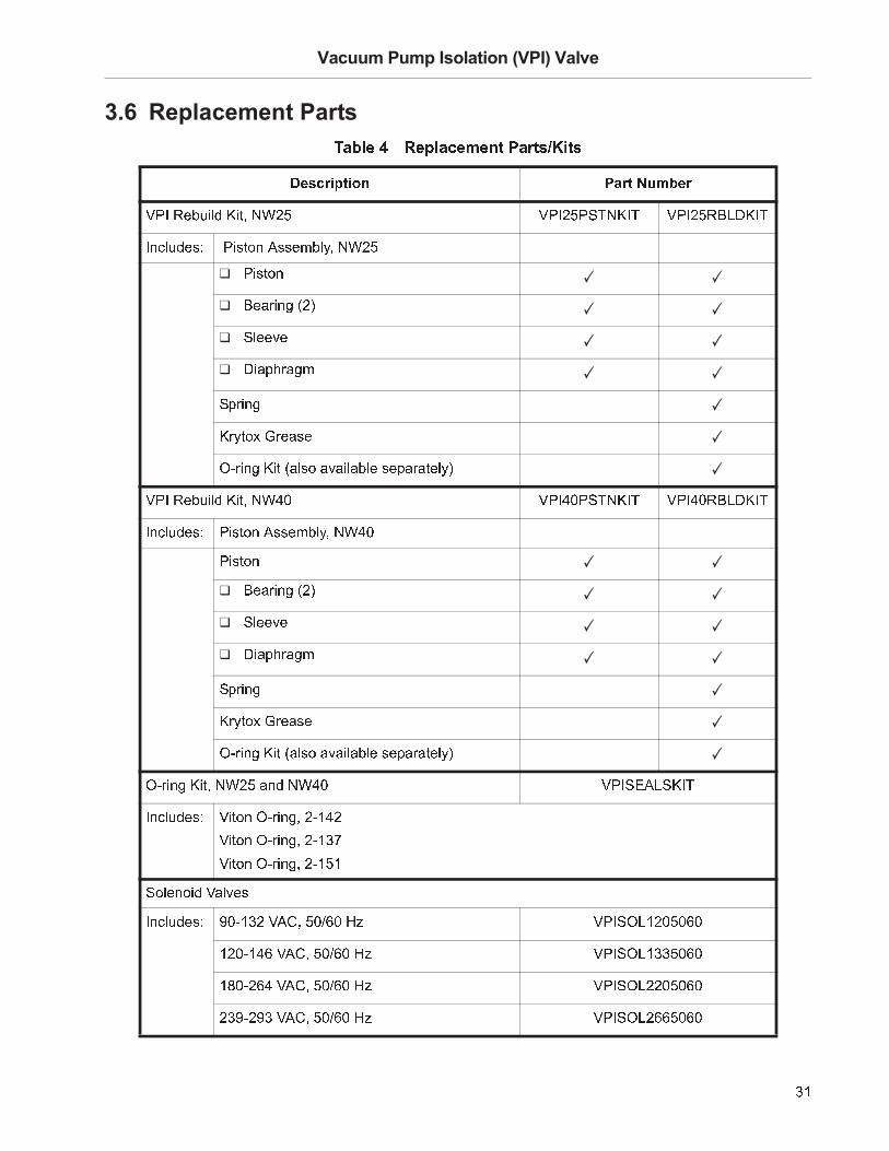
Y Z [ \ ] ^ � � n n ^ � i j " £ Z ^ � b d æ $ ^ a j b g ^ � ^ d c ¾ b ] c nThese instructions refer to Figure 6. Circled items are replacement parts. Items 1 through 4 are part of the Piston Assembly (see Section 3.6 “Replacement Parts” on page 31).
1. Remove the six 10-32 x 7/8 socket head cap screws from the bonnet.
2. Remove the bonnet with the solenoid valve still attached.
3. Remove the diaphragm/piston assembly by gently prying up the diaphragm at one edge and pulling free of the body around the full circumference. Inspect the diaphragm for holes, tears, or accumulated contamination and the orifices and for blockage.
¾ _É m � � \ d Z g b c Z m dÉ b i j ^ £ ¾ ¿ £ b j À ^
Ç b Z d n ¾ m � ^ ] ¿ d a \ ce a j Z c c ^ ] É m ] æ� � � !¾ m � ^ ] e \ a a j "

{ X
4. Inspect the nose piece ➄ O-ring carefully. It must be replaced if it is scratched or imbedded with foreign material
1. Remove the diaphragm ➃ from the piston by unscrewing the sleeve ➂ from the piston using a spanner wrench. Inspect the orifices and clean if necessary. Be careful not to enlarge the orifices, because performance may suffer. Inspect the diaphragm ➃ for holes, tears, or accumulated contamination. Discard it if damaged.
2. Inspect the dry bushings ➁ pressed into the sleeve ➂. These bushings are normally good for several hundred thousand cycles, but they can be replaced when they have worn out. A worn bushing can be identified by excessive exposure of the sintered bronze matrix, which is not normally visible. A modest amount of lead /PTFE flakes in and around the bushing and pin is normal and does not constitute abnormal wear of the bushing. If there is any doubt about the condition of the bushings, they should be replaced. Remove by inserting a number 10 machine screw and pulling. There are two ¼ in. long bushings used in tandem. After removal of the old bushings inspect the bore in the sleeve ➂ for debris and burrs. Clean as necessary. Press two new bushings into the bore, one at a time, flush to the top of the sleeve.
3. To reassemble, place the diaphragm ➃ on the piston with the inner bead down and the outer bead up (Figure 6 on page 23). A small amount of vacuum compatible grease should be smeared on the sleeve side of the diaphragm/sleeve contact area to prevent puckering of the diaphragm during tightening of the sleeve. Also, if the piston and sleeve have been degreased prior to assembly, a small amount of vacuum compatible lubrication should be applied to the male threads of the sleeve to prevent seizing of the sleeve to the piston. DuPont Krytox® GPL 206 is acceptable. Tighten the sleeve hand tight. Do not overtighten, this is not a vacuum grade seal.

{ F
The nose piece O-ring ➄ should be removed only if a new replacement is available.
To remove the old O-ring:
1. Insert a sharp pointed tool, such as a machinist’s scribe obliquely into the ring. The sharp point must not pass through the seal or the surface of the groove will be damaged. Lift the seal out with the scribe. Use care not to scratch any of the sealing surfaces.
2. Prepare the new seal by smearing a very light but continuous coat of a vacuum compatible grease on the O-ring. DuPont Krytox® GPL206, a high quality fluorinated grease offering low vapor pressure, excellent temperature stability and is chemically inert is recommended — do not skip this step. Tests have indicated that a dry nose piece O-ring used in a valve that has been closed for more than two hours is subject to a breakaway friction exceeding the modest return spring force.P V U W
The return spring has intentionally been designed to be soft so as to minimize the opening remote pressure burst, thereby necessitating a boundary layer lubrication at the nose piece O-ring to control the breakaway friction between the valve seat and the O-ring.
To replace the seal:
❑ Position the piston ➀ so that the groove faces upward. Be sure that the bottom of the groove and surfaces of the new O-ring are free of scratches. If necessary, a suitable solvent may be used to clean the groove. Particulate contamination may be blown off with Dust-Off® or dry nitrogen. Place the prepared O-ring from step 2 above on top of the groove. Place two thumbs on the O-ring at points 180 degrees apart, and push the O-ring into the groove. Avoid twisting the O-ring as it is pushed in. Then push in the opposite intermediate points, and so on, until the ring is uniformly in place.

{ G
Y Z [ \ ] ^ % � n n ^ � i j " £ Z ^ � b d æ $ ^ a j b g ^ � ^ d c ¾ b ] c nRefer to Figure 7 for these instructions.
1. Slide the piston/diaphragm subassembly onto the guide pin. With the piston facing up so it does not slide off of the guide pin, place the body down over the piston, flat surface to the diaphragm. Now invert the body with the bonnet held close and align the bolt holes. Insert six 10-32 x 7/8 in. socket head cap screws and tighten to 27 in-lb torque.
2. Before returning the valve to service, it should be leak tested.P V U WPower will need to be supplied to the solenoid in order to check the integrity of the body seals as well as the solenoid itself.
& '

{ H
This section is a guide for solving problems that may occur with the VPI valve. Listed below are symptoms with possible causes and suggestions for help.
1. Valve leaks from external atmosphere into vacuum system. First check that the solenoid has proper electrical power applied to the coil. If the solenoid appears to be functional, then carefully leak test with a quality leak detector. With careless leak detection, a leak a large distance away can be picked up and the leaking component not found. Some possible sources of leaks are:
a. Nonsealing flanges between valve and system may be due to damaged flanges, damaged O-ring, dirt, loose clamps, or incorrect assembly. Locate the problem and assemble correctly.
b. If a leak signal is obtained at the solenoid/bonnet connection, disassemble, clean, and reassemble.
c. A leak signal at the solenoid intake indicates a defective solenoid valve. Disassembly of the solenoid valve is not recommended. Install a new solenoid valve (see Table 4 on page 31 for part numbers).
2. VPI Valve is dirty and contaminated with a material that is outgassing or blocking the orifices. Correct by thoroughly cleaning the valve.S N T U Q V P
If the solenoid valve is replaced by a unit not supplied by Agilent, it is the responsibility of the user to ensure that it is sufficiently leak tight to meet the specifications.
1. Check for proper installation. The valve has been designed to vent the roughing pump upon closure. If the valve has inadvertently been installed backwards it would isolate the pump and vent the system. Reinstall the valve correctly with the flow arrow on the body label pointing toward the mechanical vacuum pump.
2. The nose piece O-ring ➄ leaks. Confirm leak using a leak detector. Replace O-ring as described previously.

{ �
1. Inlet filter to solenoid valve is clogged. Clean or replace filter.
2. Solenoid valve is defective. Replace with a new solenoid valve.
3. There is excess friction between bushing ➁ and guide pin. Clean and repair the bushing and guide pin as described in Section 3.2.1 “Piston/Diaphragm Sub-Assembly” on page 24.
4. The spring is restricted by contamination. Disassemble, clean, or replace.
1. The orifices are partially blocked. Clean and reassemble.
2. There is excess friction between bushing ➁ and guide pin. Clean and repair the bushing and guide pin as described in Section 3.2.1 “Piston/Diaphragm Sub-Assembly”.
3. The diaphragm ➃ or spring is contaminated. Disassemble, clean or replace, and reassemble.
1. The solenoid valve has a leak or will not close properly preventing the evacuation of the chamber over the piston. Check to make sure that electrical power has been restored to the solenoid valve. If the solenoid valve is energized, leak check. If a leak is found in the solenoid, replace the solenoid.
2. Foreline between the mechanical pump and VPI valve has a major leak preventing the evacuation of the chamber over the piston. Isolate and correct the leak.
3. Excess friction between bushing ➁ and guide pin. Clean and repair bushing as described in Section 3.2.1 “Piston/Diaphragm Sub-Assembly” on page 24.
4. The nose piece O-ring ➄ is stuck to valve seat due to excess heat, contamination or the improper installation of a dry (ungreased) O-ring. Follow the instructions in Section 3.2.2 “Nose Piece O-ring Replacement”.
5. The diaphragm ➃ or spring is contaminated. Disassemble, clean or replace, and reassemble.
1. Diaphragm ➃ is damaged. Replace with a new diaphragm, see Section 3.2.1 “Piston/Diaphragm Sub-Assembly”.
2. Diaphragm ➃ has become detached from piston ➀ and sleeve. Inspect and reassemble as described in Section 3.2.1 “Piston/Diaphragm Sub-Assembly” on page 24.

{ J
1. This is a continuous duty valve equipped with Viton seals capable of sustained high temperature operation. A 85° C temperature rise is normal for this valve.
2. Coil and operating voltage/frequency not matched. Change the solenoid coil to one with a voltage/frequency compatible with the pump. See Table 3 on page 18.
3. The ambient temperature is too high. The ambient temperature near the solenoid is limited to less than 50° C due to the temperature rise inherent in the solenoid valve. Higher temperature rated coils are available on a special request basis if the ambient cannot be controlled to the 50° C temperature limit. Replace the solenoid valve with a new one (see Table 3 on page 18) if the unit is too hot and verify that the ambient air temperature is within limits. P V U W
It is permissible to remotely place the solenoid valve up to twelve inches away from the VPI valve using standard ¼ in. tubing, but this could adversely affect the closing time.S N T U Q V PIf the solenoid valve is replaced by a unit not supplied by Agilent, it is the responsibility of the user to ensure that it is sufficiently leak tight to meet the specifications.
$ L
The VPI valve was designed for user repair, but occasionally it is necessary to return a valve to the factory. Before shipping, observe the following steps:
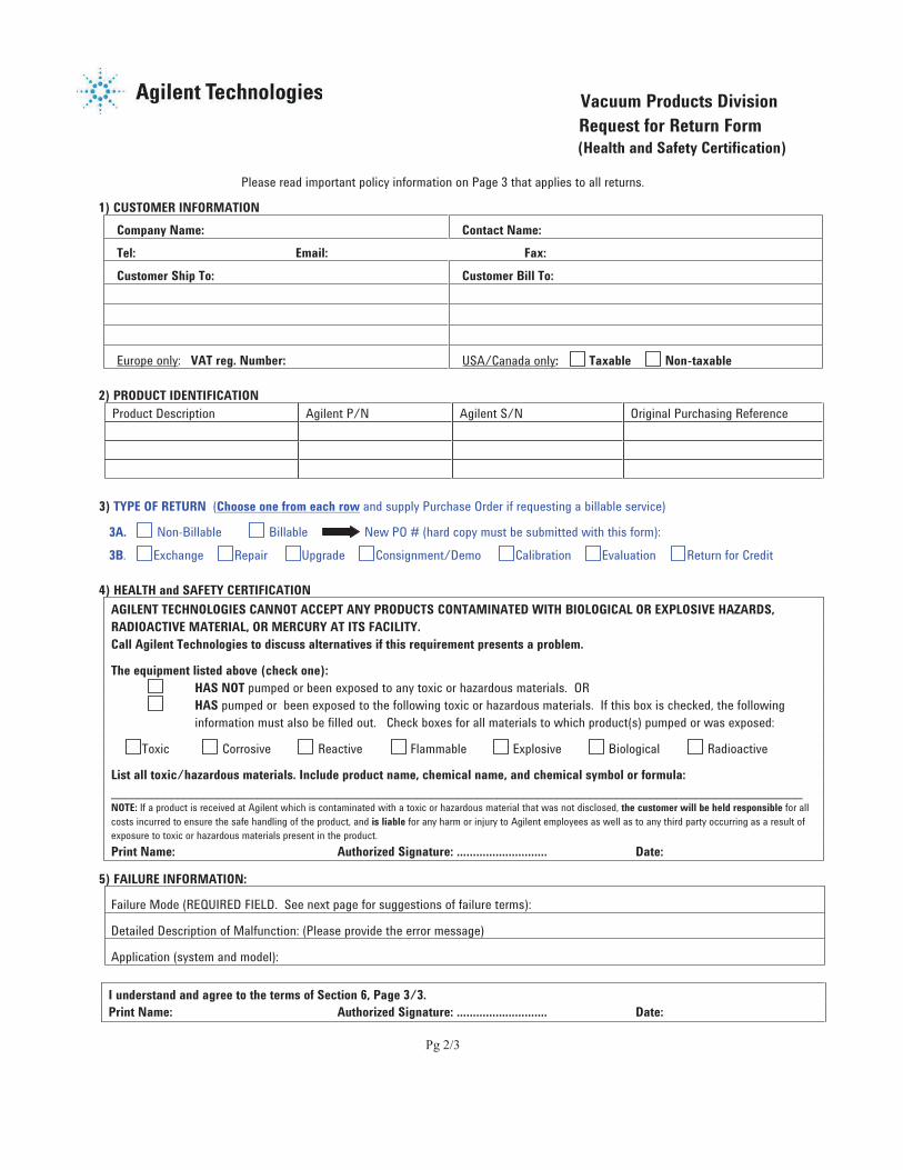
1. Call Agilent to obtain a Returned Material Authorization (RMA) number. You will be asked to fax a completed copy of the Health and Safety Certification form, located in the back of this document, before an RMA number is issued. This form is used to certify that the product to be returned does not present any health or environmental risks or dangers; please read carefully.P V U W
Y Z [ \ ] ^ ( É m d c b g c � [ Z j ^ d c É \ n c m � ^ ] e ^ ] À Z g ^ c m m i c b Z d b $ ^ c \ ] d Ç b c ^ ] Z b j n � \ c k m ] Z ) b c Z m d å $ Ç � çd \ � i ^ ] b d æ b * ^ b j c k b d æ e b l ^ c " Á b c b e k ^ ^ c + $ ^ c \ ] d m l b d " a b ] c � \ n c i ^ b g g m � a b d Z ^ æ i " i m c km l c k ^ n ^ g m � a j ^ c ^ æ l m ] � n m ] c k ^ n k Z a � ^ d c � Z j j d m c i ^ b g g ^ a c ^ æ +2. Use the RMA number on all packing slips, boxes, and be prepared to answer the
following questions:
a. What is the problem?
b. What are the symptoms and how are they observed?
c. What is the application?
d. Is it an emergency repair?
e. Is it a warranty repair? When was the valve shipped to you?
f. Who in your organization can answer technical questions about the use of the valve?
3. Prepare the valve for shipment by capping the ports to prevent entry of foreign material and to protect the seal surfaces. Place the valve in a sealed plastic bag, and pack it securely in a sturdy shipping container. Insert a packing slip or letter referencing the RMA number.
4. If inspection shows the problem to be a warranty matter, the valve will be repaired and returned free of charge. If it is not covered by warranty, you will be charged for repairs.
$ K
h b i j ^ � $ ^ a j b g ^ � ^ d c ¾ b ] c n , - Z c nà « .  ¬ ¶ ¸ ¶ ´ µ § ¨ ¬ P ® ¯ ° « ¬� � y / � v � r u w 0 r � 1 o � { F � � y { F � � � o 0 y � � � y { F / � � z 0 y �y s � u � w � � 2 � r � � p s � � � � q v u x 1 o � { F❑ 3 4 5 6 7 8 ✓ ✓
❑ 9 : ; < 4 8 = > ? @ ✓ ✓
❑ A B : : C : ✓ ✓
❑ D 4 ; E F < ; = G ✓ ✓A E < 4 8 = ✓H < I 6 7 J K < : ; 5 : ✓L M < 4 8 = H 4 6 > ; B 5 7 ; C ; 4 B ; N B : 5 : E ; < ; 6 : B I @ ✓O 3 P Q : N R 4 B S H 4 6 T U V W X O 3 P W X 3 A Y U H P Y O 3 P W X Q 9 Z D H P YP 8 [ B R S : 5 \ 3 4 5 6 7 8 ] 5 5 : G N B I T U V W X3 4 5 6 7 8 ✓ ✓
❑ 9 : ; < 4 8 = > ? @ ✓ ✓
❑ A B : : C : ✓ ✓
❑ D 4 ; E F < ; = G ✓ ✓A E < 4 8 = ✓H < I 6 7 J K < : ; 5 : ✓L M < 4 8 = H 4 6 > ; B 5 7 ; C ; 4 B ; N B : 5 : E ; < ; 6 : B I @ ✓L M < 4 8 = H 4 6 T U V ? ^ ; 8 S U V W X O 3 P A _ ] Z A H P YP 8 [ B R S : 5 \ O 4 6 7 8 L M < 4 8 = T ? M ` W ?O 4 6 7 8 L M < 4 8 = T ? M ` a bO 4 6 7 8 L M < 4 8 = T ? M ` ^ `A 7 B : 8 7 4 S O ; B C : 5P 8 [ B R S : 5 \ c X M ` a ? O ] d T ^ X e f X g h O 3 P A L Z ` ? X ^ X f X` ? X M ` W f O ] d T ^ X e f X g h O 3 P A L Z ` a a ^ X f X` i X M ? f W O ] d T ^ X e f X g h O 3 P A L Z ? ? X ^ X f X? a c M ? c a O ] d T ^ X e f X g h O 3 P A L Z ? f f ^ X f X

This page intentionally left blank.

This page intentionally left blank.
Pg 1/3
NORTH AMERICA:
Fax: 1 781 860 9252
Toll Free: 800 882 7426, Option 3
PACIFIC RIM:
please visit our website for individual
office information
http://www. .com
EUROPE:
Fax: 00 39 011 9979 330
Fax Free: 00 800 345 345 00
Toll Free: 00 800 234 234 00
Vacuum Products Division
Instructions for returning products
Dear Customer:
Please follow these instructions whenever one of our products needs to be returned.
1) Complete the attached Request for Return form and send it to Agilent Technologies (see below), taking particular care to identify
all products that have pumped or been exposed to any toxic or hazardous materials.
2) After evaluating the information, Agilent Technologies will provide you with a Return Authorization (RA) number via email or fax,
as requested.
Note: Depending on the type of return, a Purchase Order may be required at the time the Request for Return is submitted. We
will quote any necessary services (evaluation, repair, special cleaning, eg).
3) Important steps for the shipment of returning product:
Remove all accessories from the core product (e.g. inlet screens, vent valves).
Prior to shipment, drain any oils or other liquids, purge or flush all gasses, and wipe off any excess residue.
If ordering an Advance Exchange product, please use the packaging from the Advance Exchange to return the defective
product.
Seal the product in a plastic bag, and package product carefully to avoid damage in transit. You are responsible for loss or
damage in transit.
Agilent Technologies is not responsible for returning customer provided packaging or containers.
Clearly label package with RA number. Using the shipping label provided will ensure the proper address and RA number
are on the package. Packages shipped to Agilent without a RA clearly written on the outside cannot be accepted and will
be returned.
4) Return only products for which the RA was issued.
5) Product being returned under a RA must be received within 15 business days.
6) Ship to the location specified on the printable label, which will be sent, along with the RA number, as soon as we have received
all of the required information. Customer is responsible for freight charges on returning product.
7) Return shipments must comply with all applicable Shipping Regulations (IATA, DOT, etc.) and carrier requirements.
RETURN THE COMPLETED REQUEST FOR RETURN FORM TO YOUR NEAREST LOCATION:
This page intentionally left blank.
Pg 2/3
Vacuum Products Division
Request for Return Form
(Health and Safety Certification)
Please read important policy information on Page 3 that applies to all returns.
1) CUSTOMER INFORMATION
Company Name: Contact Name:
Tel: Email: Fax:
Customer Ship To: Customer Bill To:
Europe only: VAT reg. Number: USA/Canada only: Taxable Non-taxable
2) PRODUCT IDENTIFICATION
Product Description Agilent P/N Agilent S/N Original Purchasing Reference
3) TYPE OF RETURN (Choose one from each row and supply Purchase Order if requesting a billable service)
3A. Non-Billable Billable New PO # (hard copy must be submitted with this form):
3B. Exchange Repair Upgrade Consignment/Demo Calibration Evaluation Return for Credit
4) HEALTH and SAFETY CERTIFICATION
AGILENT TECHNOLOGIES CANNOT ACCEPT ANY PRODUCTS CONTAMINATED WITH BIOLOGICAL OR EXPLOSIVE HAZARDS,
RADIOACTIVE MATERIAL, OR MERCURY AT ITS FACILITY.
Call Agilent Technologies to discuss alternatives if this requirement presents a problem.
The equipment listed above (check one):
HAS NOT pumped or been exposed to any toxic or hazardous materials. OR
HAS pumped or been exposed to the following toxic or hazardous materials. If this box is checked, the following
information must also be filled out. Check boxes for all materials to which product(s) pumped or was exposed:
Toxic Corrosive Reactive Flammable Explosive Biological Radioactive
List all toxic/hazardous materials. Include product name, chemical name, and chemical symbol or formula:
________________________________________________________________________________________________________NOTE: If a product is received at Agilent which is contaminated with a toxic or hazardous material that was not disclosed, the customer will be held responsible for all
costs incurred to ensure the safe handling of the product, and is liable for any harm or injury to Agilent employees as well as to any third party occurring as a result of
exposure to toxic or hazardous materials present in the product.
Print Name: Authorized Signature: ………………………. Date:
5) FAILURE INFORMATION:
Failure Mode (REQUIRED FIELD. See next page for suggestions of failure terms):
Detailed Description of Malfunction: (Please provide the error message)
Application (system and model):
I understand and agree to the terms of Section 6, Page 3/3.
Print Name: Authorized Signature: ………………………. Date:
This page intentionally left blank.
Pg 3/3
Vacuum Products Division
Request for Return Form
(Health and Safety Certification)
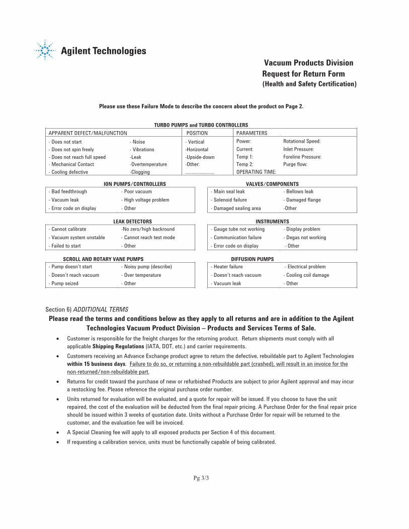
Please use these Failure Mode to describe the concern about the product on Page 2.
TURBO PUMPS and TURBO CONTROLLERS
APPARENT DEFECT/MALFUNCTION POSITION PARAMETERS
- Does not start - Noise - Vertical Power: Rotational Speed:
- Does not spin freely - Vibrations -Horizontal Current: Inlet Pressure:
- Does not reach full speed -Leak -Upside-down Temp 1: Foreline Pressure:
- Mechanical Contact -Overtemperature -Other: Temp 2: Purge flow:
- Cooling defective -Clogging …………………. OPERATING TIME:
ION PUMPS/CONTROLLERS VALVES/COMPONENTS
- Bad feedthrough - Poor vacuum - Main seal leak - Bellows leak
- Vacuum leak - High voltage problem - Solenoid failure - Damaged flange
- Error code on display - Other - Damaged sealing area -Other
LEAK DETECTORS INSTRUMENTS
- Cannot calibrate -No zero/high backround - Gauge tube not working - Display problem
- Vacuum system unstable - Cannot reach test mode - Communication failure - Degas not working
- Failed to start - Other - Error code on display - Other
SCROLL AND ROTARY VANE PUMPS DIFFUSION PUMPS
- Pump doesn’t start - Noisy pump (describe) - Heater failure - Electrical problem
- Doesn’t reach vacuum - Over temperature - Doesn’t reach vacuum - Cooling coil damage
- Pump seized - Other - Vacuum leak - Other
Section 6) ADDITIONAL TERMS
Please read the terms and conditions below as they apply to all returns and are in addition to the Agilent
Technologies Vacuum Product Division – Products and Services Terms of Sale.
Customer is responsible for the freight charges for the returning product. Return shipments must comply with all
applicable Shipping Regulations (IATA, DOT, etc.) and carrier requirements.
Customers receiving an Advance Exchange product agree to return the defective, rebuildable part to Agilent Technologies
within 15 business days. Failure to do so, or returning a non-rebuildable part (crashed), will result in an invoice for the
non-returned/non-rebuildable part.
Returns for credit toward the purchase of new or refurbished Products are subject to prior Agilent approval and may incur
a restocking fee. Please reference the original purchase order number.
Units returned for evaluation will be evaluated, and a quote for repair will be issued. If you choose to have the unit
repaired, the cost of the evaluation will be deducted from the final repair pricing. A Purchase Order for the final repair price
should be issued within 3 weeks of quotation date. Units without a Purchase Order for repair will be returned to the
customer, and the evaluation fee will be invoiced.
A Special Cleaning fee will apply to all exposed products per Section 4 of this document.
If requesting a calibration service, units must be functionally capable of being calibrated.

This page intentionally left blank.


j k l m n o p q l r s tu v w x y z { | y } ~ z � x � v w y �� � � � � � { � y x x u � y z � y� y � w z v { � z � � u � � � � � � � u| y x � � � � � � � � � � � � � �| � x x � � � y y � � � � � � � � � � � � �� � � � � � � � � � � � � � � �� � x � } � � { � � y � � y � � w } y � � v w x y z { � } � �� q � q ¡ ¢u v w x y z { | y } ~ z � x � v w y � £ y { ~ y � x � z ¤ � ¥ � ¦ �� y � } � x y � � y v �� � � � § � � w ¤ ¤ y x ¨ � � v | ~ y £ y { ~ y � x � z ¤ �| y x � � � � � � � � � � � � �� � � � � � � � � � � � � � � ©| � x x ª � y y � � � � � � � � � � � � � �« n r � tu v w x y z { | y } ~ z � x � v w y � ¬ ~ w z � ® � � � { ¤£ � � � � ¯ � z v ° w z v ¥ y w � � � ~ � � ± � z v ² w � �{ � w } { � ¥ y w ³ w z v � � � � � � � ~ w z � | y x � � � � � ¬ � � ®� � � © � � � �� � � � � � � ¬ � � ® � � � © � � � �| � x x � � � y y � � � � � � � � � � �� � } � } � � { � � y � � y � � w } y � � v w x y z { � } � �´ l t � s qu v w x y z { | y } ~ z � x � v w y � � � � z } y� � � y z � y ¤ y � | � � � w µ � y �¶ � u � ¤ y � � � { � ¨ � y � ª � ¥ � § � � �© � © � � � y � � x w � } y ¤ y � � � � z } y| y x � � � � � ¬ � ® � � © � � � � � �� � � � � � � ¬ � ® � � © � � � © � �| � x x ª � y y � � � � � � � � � � � � � �� � ª � � � x y � � � v w x y z { � } � �· q l p t � ¸ ¹ o ¡ º m l r tu v w x y z { | y } ~ z � x � v w y �� » � z y � � { � � � �� � � � � � � � z ¼ ª � � { � � � � w z ½ y � � � z »| y x � � � � © � © � � � � � � � � � �� � � � � � © � © � � � � � � � � � �| � x x ª � y y � � � � � � � � � � � � � �| ~ w � w z ª � � � � { w � z w � � � ¨ ³ y } { { � } ~ � z v y� w { ~ � � { z � { w } y �¾ u v w x y z { | y } ~ z � x � v w y � � ¿ z } � � � � � �§ � ¨ x w � ~ y ¤ w z � � u � ² y } y � ¨ y � � � � � �
À � Á r tu v w x y z { | y } ~ z � x � v w y � ¿ z ¤ w � § � { � � { ¤ �½ � � � § � w � y } � � � � � � { y § � � ¼ �� � �  � � � � � � ~ � � à � � ¤ �Ä � � � ¥ x � y ² � � { y z { � y �u z ¤ ~ y � w ¬ Å � � { ® � � � � ¨ � w Æ � � � � © © � ¿ z ¤ w �| y x � � © � � � � � � � � � � �  � � � �� � � � � © � � � � � � � � � � �| � x x � � y y � � � � � � � � � � �} � v Ç w z ¤ w � � � v w x y z { � } � �À m t ¸u v w x y z { | y } ~ z � x � v w y � ¿ { � x w � � � � � u �� w � � � x x w ¦ � � w � z � �� � � � � � y w z w � ¬ | � � w z � ® ¿ | u � ±| y x � � � � © � � � © © � © � � �� � � � � � © � � � © © � © � � �| � x x � � � y y � � � � � � � � � � � � � �� � { � � � x y � � � v w x y z { � } � �� � { � } � � { � � y � � y � � w } y � � v w x y z { � } � �È t É t �u v w x y z { | y } ~ z � x � v w y � ° � � � z � � { ¤ �� { ~ � x � � � � � � � w { � � � � ~ w ¨ � � � � ¥ � w x ¤ w z v� � � � � � � � ~ w ¨ � � � � � w z � { � � ¼ �| � ¼ » � � � � ° u § u £| y x � � � � � � � � � � � � � �| � x x � � � y y � � � � � � � � � � �� � � � � � � � � � � � � � � �� � ³ � } � � { � � y � � y � � w } y � � v w x y z { � } � �Ê k l q tu v w x y z { | y } ~ z � x � v w y �� ~ w z � � � z ¤ ¥ x ¤ v � � �© � � � � ² � y } ~ w � ¤ � z vË � z v z � � � v � � � y � � x Ë Ä Ã Å u � � � � � � �| y x � � � � � � � � � � � � � �| � x x � � � y y � � � � � � � � � � �� � � � � � � � � � � � � � � �� � ¼ � } � � { � � y � � y � � w } y � � v w x y z { � } � �Ì r � Í t É k l qu v w x y z { | y } ~ z � x � v w y � � w z v � � � � y § { y � � { ¤£ � � � ± w � ~ � z u � y z � y � � w z v � � � � y � � � © � �| y x � � � � � � � � � � � �� � � � � � � � � � � � � � �| � x x � � � y y � � � � � � � � � � � �� � � � } � � { � � y � � y � � w } y � � v w x y z { � } � �
Ì k ¡ m n q t º m o º r tu v w x y z { | y } ~ z � x � v w y � � � x y � � ¤ z ¥ ~ ¤� z w { � � � � � y � y x � � � { � � z � �� ° � x � z � � � �  � � � ² � � � z � � � � � � { � � z� � � � � § y { � x w z v ° � » � � � y x � z v � � � � � x � » � w �| y x � � � � � � � � � � � � �� � � � � � � � � � � � � � � �| � x x � � � y y � � � � � � � � � � �� � � � } � � { � � y � � y � � w } y � � v w x y z { � } � �Î t r Ï t �u v w x y z { | y } ~ z � x � v w y � | � w � � z � w � w { y ¤� � Ë � � � � ~ � � z v à ¤ � � § w z � ~ y z w { » � � � �| � � » � � z � � w y z � | � w � � z � à � Ä � � | y x � � � � �� � © � © � � �| � x x � � y y � � � � � � � � � � �� � � � } � � { � � y � � y � � w } y � � v w x y z { � } � �Ð Ê ¹ À l q t � Áu v w x y z { | y } ~ z � x � v w y �� � y � ¤ à � � ¤Ä � ª � � ¤ ¿ z ¤ � � { � w � x § � � ¼± � � z { � z � Ä � ª � � ¤ Ä Ñ � � Ò � � Ë| y x � � � � � ¬ � ® � � � � � © � � � �� � � � � � � ¬ � ® � � � � � © � � � �| � x x ª � y y � � � � � � � � � � � � � �� � { � } � � { � � y � � y � � w } y � � v w x y z { � } � �Ó Ô Õ Ö × Ø Ù Ö Ô ÚÛ Û Û Ü Õ Ý Þ ß Ô × à Ü á Ù Ø â á ã Ô Ø â ä Õ á å å Ø