Embed Size (px)
Citation preview

) V
UNITED STATES DEPARTMENT OF THE INTERIOR
BUREAU OF RECLAMATION
A STUDY OF A DISCHARGE REGULATOR FOR THE POLE HILL SIPHON
COLORADO-BIG THOMPSON PROJECT
Hydraulic Laboratory Report No. Hyd-335
ENGINEERING LABORATORIES BRANCH
DESIGN AND CONSTRUCTION DIVISION DENVER, COLORADO
May 12, 1952

The information contained in this re -port may not be used in any publication, advertising, or othe r promotion in such a manner as to constitute an endorsement by the Government or the Bureau of Reclamation, either explicil or implicit, of any material, product, device, or proce ss that may be re ferred to in the report.
CONTENTS
Summary ••. Introduction • • The Model. • • The Investigation
. . . . . . ~ . . . . . , . . . .
. . . . . . . . . . . . . . . . . . ., . . . . . . . . . . . . . . . . . . . . . . . . . . . . . . . . . . . . . . . . .
Discussion of Siphonic Flow • • • • • • General Discussion of Tests . . . . .
Criteria for Good Performance . . Model-prototype Relation • . . . .
Adaptation of Siphon-breaker Pipe • . . Multiple Air Conduits • • . . . . . .
Pipe Conduits • • • • • Rectangular Conduits • • •
. . . .
• • . . . . . . . . • •
. .
• • • • • • . . . . • . • . . • . . . . . . . . . • . . . . . . . . . • • • . . . . . . . . . . . . . . . . . .
Slot Controls . . . . . . . . . . . . . . . . . . . . . Horizontal Slots- -Orifice Type
Priming characteristics Operation • • • • • • . •
• •
Horizontal Slots--Solid-wall Type •
Operation •
Vertical Slots • . . . Priming ••• Operation • •
. . . .
. . . . . .
. . . . . . . . . . . .
. . . . . . . . . . . . . . . . . . . .
• • • • . . . . . . . . . . . . . . . . . . . . .
Comparison of Horizontal and Vertical Slots . . . . . Discharge regul8:tion • • • • • Reservoir elevation regulation
. . . . . . . . .
Recommendations . . . . . . . . . . . . . . .. . . . . .
Page
1 2 3 4
4 5
5 5
5 6
7 7
8
9
9 9
10
10
11
11 11
12
12 12
12
Figure
Damage at the discharge end of the Marys Lake Siphon. • • • • 1 Siphon installation, nomenclature and dimensions • • • • • • • 2 Adaptation of siphon-breaker pipe • • • • • • • • • • • • • 3
i
CONTENTS--Continued
Figure
Multiple pipe conduit • • • • • • • • . • • • • • • . • • • • 4 Rectangular conduit • • • • • • • • . • • • • • • • • • • • 5 Horizontal orifice-type slots • • • • • • • • • • • • • • • • 6 Horizontal orifice-type slot, discharge--1 second-foot • • • • • 7 Horizontal orifice-type slot, discharge--4 second feet • • • • • 8 Horizontal orifice-type slot, discharge--8 second feet • • • • • 9 Discharge curves • • • • • • • • • • • • • • • • • • • • • 10 Horizontal solid-wall-type slots • • • • • • . • • • • • • • • 11 Vertical orifice-type slots • • • . • • • . • • • • • • • • • 12 Vertical orifice-type slot, discharge- .. 1 second-foot • • • • • • 13 Vertical orifice-type slot, discharge- .. 4 second feet • • • • • • 14 Vertical orifice-type slot, discharge--8 second feet • • • • • • 15 Discharge cycles • • • • • • • • • . • • • • . • • • • • • 16 Comparison of flow in siphon barrel, discharge--2 second feet • 17
ii

UNITED STATES DEPARTMENT OF THE INTERIOR
BUREAU OF RECLAMATION
Design and Construction Division Engineering Laboratories Branch Denver,· Colorado
Laboratory Report No. Hyd-335 Hydraulic Laboratory Section Compiled by: T. J. Rhone Reviewed by: A. J. Peterka May 12, 1952
Subject: A study of a discharge regulator for Pole Hill Siphon--ColoradoBig Thompson Project
SUMMARY
The model studies presented in this report were made to determine the possibility of regulating the flow through a siphon spillway by admitting air into the throat.
Three methods of admitting air into the siphon were investigated:
1. Through the siphon breaker pipe, Figure 3
2. Through multiple air conduits, Figure 4
3. Through slotted openings in the roof of the siphon, Figures 6 and 12
The first method did not provide regulation over a sufficiently wide range of discharge. The second method provided better regulation, but the number of conduits needed to provide full regulation resulted in a cumbersome device that would be impracticable for field construction.
The third method, recommended for field installation, provided excellent regulation. With the slots in a horizontal position, the siphon was regulated for about 94 percent of the discharge range; with the slots in a vertical position, there was regulation for the full discharge range.
Since it was desired to utilize on the Pole Hill Siphon the slotted regulator developed in these tests and since the model tests were limited in scope in that they did not establish the quantity of air needed to provide the proper air-water mixture for the prototype structure, recommendations were made to install a completely adjustable opening for the prototype regulator. Then, based on field tests, the slot area needed to regulate the prototype siphon can be determined and set. Recommendations were also made to obtain comprehensive data which can be compared with model data to provide a better understanding of the regulator for future designs.

INTRODUCTION
Several structures in-the Colorado-Big Thompson Project make use of siphon spillways to provide a method of discharging the flow in cases of emergency, such as power plant failure.
At one of. these structures, the Pole Hill Power Plant., it was found necessary to-provide for a small diversion flow during the completion of the power plant and penstock. The only available structure for discharging this diversion flow was the Pole Hill Siphon.
The quantity of the diversion flow was considerably smaller than the design discharge of the siphon. Since a siphon operates only at or near its maximum discharge, an intermittent flow condition would result which would be dangerous to the construction workers and fishermen in the area below the power plant.
_ . If a method could be found to regulate the discharge of the siphon it would eliminate the necessity of constructing an expensive turnout structure upstream in the canal.
During the course of the laboratory investigations, water was turned into another of the Colorado-Big Thompson structures, the Marys Lake Siphon. The operation of the siphon spillway was not satisfactory, and considerable damage occurred at the discharge end of the siphon, Figure 1. When the siphon was fully primed it discharged approximately 500 second feet, the inflow into the forebay of the siphon was about 200 second feet. Due to the comparatively small forebay area, the discharge lowered the water level 30 inches in approximately 15 seconds, allowing air to be admitted through the siphon breaker to break the prime of the siphon and stop the flow. It took approximately 30 seconds for the fore bay to refill to the original level, whereupon the siphon primed again and the cycle was repeated. At the discharge end of the siphon, the highvelocity flow from the siphon swept the tail water away from the outlet; when the flow ceased there was a reversal of flow in the tail water and it moved back toward the discharge end of the siphon. About the time that the outlet was fully sub,merged the siphon was discharging again and the two flows., traveling in opposite directions, collided inside the downstream end of the siphon, producing tremendous pressures within the structure. The resulting stresses were the cause of the damage to the structure as shown in Figure 1.
_ In most installations there is no problem as described above, but there still remains a serious objection to the ordinary siphon. The characteristic action of a siphon is to discharge the maximum flow whenever it oper~tes and conse_quently, the protective works at the discharge end must be .capa,b~e 9f dissipating. ·the energy in the maximum flow at all times, resulting . in an expensive structure.
If a satisfactory type of regulator could be developed., it could be installed in new and existing siphon spill ways and would serve the dual purpose of preventing or lessening the probability of damage at the outlet of the siphon and would also regulate the siphon outflow so that the larger discharges would occur only when necessary.
2

A regulated siphon spillway could be used to safely pass the low flows that occur most of the time and still retain the advantage of having sufficient capacity to pass the maximum flow in an emergency. The protective· works could then be designed to produce excellent flow conditions at all times for the normal flow and to handle short-period emergency flows without damage to the structure. Experience has shown this method to be less costly than providing safe protective works for the maximum discharge at all times.
The possibility that a regulator could be developed was indicated in a paper in the 1938 Proceedin s of the American Society of Civil En ineers, page 1627, entitled "Sip ons as ater eve egu ators, y • evens.
THE MODEL
Sufficient funds were not available to construct an exact model of the Pole Hill Siphon, so it was decided to utilize a siphon which had been constructed for another purpose and was in storage in the Hydraulic Laboratory. This siphon had been built to obtain design data on low-head siphons for Wasteway No. 2, Roza Division, Yakima Project, Washington.
The dimensions of the Yakima Siphon were not the same as any of the Colorado-Big Thompson siphons, but minor modifications were made to the model so that it would serve to indicate whether a siphon spillway could be regulated to discharge less than the maximum capacity and still remain partially primed. The top of the Yakima Siphon model was modified from the crown to the upstream lip to represent the Pole Hill Siphon; the remaining part of the structure was not changed. The scale ratio of this portion was 1:4.614.
The structure used was constructed of heavy-gage galvanized sheet iron with transparent plastic sides.
The siphon was installed in the lower end of the laboratory's steel flume. The flume is 4 feet wide, 8 feet high, and over 80 feet long. During the testing, it became apparent that even this comparatively large reservoir area was not sufficient to reproduce exactly the priming characteristics of the prototype siphon. Figure 2 shows the siphon and its installation; the nomenclature and dimensions of the various parts are also given. Photographs throughout the report show the siphon in operation.
Water was supplied to the steel flume from the permanent laboratory pumps and measured by Venturi meters. The water supply was arranged so that the flow could be diverted through a 4-, 6-, 8-, or 12-inch Venturi meter, thus assuring accurate measurement of discharge for a wide range.
The water-surface elevation of the reservoir was measured by two methods. A point gage was installed in the flume 10 feet upstream from the siphon; this was satisfactory for discharges up to 4 second feet, but for the larger discharges the wave action in the flume was too pronounced to obtain definite elevations. Therefore, a stilling-well with a hook gage was installed
3

\ on the outside of the flume, opposite the point gage, with a 1/ 2-inch insidediameter hose connecting the well with the flume. Both the hook gage and the point gage were zeroed to the elevation of the siphon crest.
In order to represent the prototyp~ exit conditions, the discharge was retained by a gate at the end of the flume so that the outlet was submerged at all flows.
THE INVESTIGATION
Discussion of Siphonic Flow
A more complete discussion of the theory of siphonic flow can be found in Hydraulic Laboratory Report No. Hyd-108. The following discussion, however, is a general review of siphon action.
When the flow starts over the crest of the siphon, it is the same as flow over a spillway crest. On the downstream side of the siphon crest, however, a small lip is placed so that the sheet of water passing over the siphon crest springs free of the surface and is deflected to the opposite side of the barrel in a thin sheet. This sheet divides the barrel into two parts and provides an air seal between the two. The flowing water in the sheet pumps air out of the throat, or upper section of the siphon, reducing the pressure to below atmospheric. As the air in the throat is exhausted water rises to take its place until the barrel is flo'Ving full. The quantity may then be computed by the orifice equation Q = CA: 2gH, with H being the difference in elevation between the reservoir and the tail-water surface.
When the throat is flowing full, the siphon is considered fully primed. As soon as the siphon starts to prime it begins to discharge a greater amount than can be passed over an open-crest weir, but the maximum capacity is obtained only when the siphon is fully primed.
Once primed, the siphon will discharge at maximum capacity until ~ir is admitted near the crown or into the throat. This is usually done by means of a siphon--breaker pipe installed near the crown of the siphon. The entrance to this pipe is placed in the reservoir at some predetermined elevation so that when the reservoir level falls to this elevation air passes through the pipe into the throat of the siphon and the prime is broken. · If the siphonbreaker entrance is below the crest elevation, flow ceases entirely. If the entrance is above the crest elevation, the flow is reduced to the amount that an open spillway crest would discharge. The reservoir water surface may then rise until the siphon again primes and the same cycle is repeated.
It has been noted on some siphons that as the reservoir level falls the discharge is reduced by an amount greater than can be accounted for by the decrease in head. This usually occurs when the reservoir level is in the vicinity of the siphon-breaker entrance. With only a thin layer of water over the breaker inlet, the siphon breaker takes air through vortices, this air mixes with the water and reduces the siphon discharge.
4

General Discussion of Tests
1, J,
Three basic types of regulators were tested. In the first type the intake end of the siphon-breaker pipe was modified so that some air was admitted at all reservoir levels, and so that as the level fell a progressively greater quantity of air was allowed to enter. The second type was a multiple air conduit having air passages under the lip of the siphon. The passages were placed so that the reservoir elevation governed the amount of air that entered; with lower water-surface elevations a greater number of the air-pa~sage entrances were exposed to the atmosphere., thus allowing greater _-:...__ quantities of air to enter. The third type of regulator consisted of a slotted opening in the top or hood of the siphon inlet located between the lip and the crown. As the reservoir level fell, a greater area of the slotted opening was exposed, allowing more air to enter.
The first two types of regulators provided some control but only from maximum flow down to about 40 percent of the maximum discharge. The third type., with slots in the hood, provided control for the full range of discharge.
Criteria for Good Performance
To determine the effectiveness of the regulating devices, reservoir elevation versus discharge curves were plotted and compared, using data obtained from the model. If the siphon under test was found to operate primed over a wide range of discharge with only a relatively small change in head, and if the outflow from the siphon increased and decreased uniformly without breaking prime as the inflow increased and decreased, the operation-was considered satisfactory.
Model-prototype Relation
All dimen~ions and discharges given in this report are actual model figures. To obtain a corresponding prototype value, the model quantity should be multiplied by the following relationshipi: for length, by t}J.e model scale N = 4. 614; area, by N2; discharge, by N° 2; velocity, by Nl/ 2. However, care should-be taken in scaling up any values involving discharges because the similarity between model and prototype siphons has not been proven in cases where pressures below atmospheric are apt to occur. Furthermore, it is known that prototype values involving entrained air cannot be predicted from the simple relationships given here.
Adaptation of Siphon-breaker Pipe
Preliminary information received by the laboratory when the testing started indicated that the construction of the Pole Hill Siphon had advanced to such a point that modifications necessary to obtain flow regulation would have to be accomplished by adding some convenient device to the existing structure rather than by modifying the structure itself. It appeared that a simple device added to the siphon-breaker pipe would serve to regulate the flow and this was tried first.
5

The siphon-breaker pipe was equipped with a sleeve at the intake end. This sleeve was made adjustable so that it could be set at different elevations or easily removed. The first regulating device tested consisted of a vertical slot cut in the lower end of this sleeve, Figure 3. The entrance to the sleeve was 3. 25 inches lower than the crest elevation, or 5. 20 inches below the maximum allowable reservoir elevation. The height of the slot was 3. 90 inches, with an adjustable width of from 0. 33 to 1. 30 inches.
The vertical slot in the siphon-breaker pipe did not produce satisfactory results. The range in the reservoir elevation was from 0. 64 foot above the crest at 7. 50 second feet to o. 05 foot below the crest at 3 second feet. At 3 second feet the flow through the siphon temporarily ceased because the siphon lost its prime. Since the reservoir elevation was below the crest, there was no flow until the inflow had raised the reservoir level above the crest, then the siphon primed and flowed near maximum discharge until the reservoir level was pulled down to a point where the air entering the slot in the siphon breaker broke the prime.
Three other types of air slots in the siphon-breaker pipe were tried. The first was a horizontal slot with its center line 0. 65 inch above the crest. The second was a combination of the horizontal and the vertical in the shape of a tee. The third was an inverted triangular opening with the base of the triangle at the same elevation as the horizontal slot. All of these modifications resulted in the same general type of action found with the vertical slot. Schematic drawings of the slots and their discharge-elevation curves are shown in Figure 3.
The four types of slots used in conjunction with the siphon-breaker pipe failed to even show promise of providing the regulation that was being sought, therefore, no further attempts were made to use the siphon breaker as a regulator.
Multiple Air Conduits
Another device that could be added to the prototype siphon spill-ways without rebuilding them was a multiple air-conduit type of regulator. This regulator consisted of multiple air conduits passing under the lip of the siphon to admit air near the crown through inlets placed at different elevations in the headwater pool. The theory behind this type of regulator was to expose more air inlets and provide a greater air supply to regulate the flow as the reservoir fell and the discharge was reduced. Two types of conduits were tested. The first consisted of relatively small diameter tubes and the other of larger rectangular passages.
Rather than make needlessly long tests to determine the effectiveness of the multiple air conduits, two necessary criteria were first checked. If one or both failed, testing was immediately stopped and a new device tested.
The criteria were: (1) to determine whether the discharge at which the siphon broke prime was sufficiently small to insure the required range of
6

continuous flow, and (2) to determine whether the difference in reservoir elevation for maximum and minimum flow was acceptable.
Pipe Conduits
The pipe conduits were made of 3/8-inch inside.-diameter rubber tubing. The tubes were placed in horizontal rows, six tubes to a row. The entrances to the first row of tubes were at approximately O. 65 inch above the crest. The tubes were passed below the lip and along the roof to a point about halfway between the lip and the crown, Figure 4. ·
___ Three tests were made with the pipe conduits. For the first test one·row of six tubes was used. The center line of the row was O. 65 inch above the crest. The discharge range on the first .test was from 8 · to 1.~ 7 second feet, but the change in reservoir elevation was too great for effective regulation. For 1. 7 second feet the reservoir was drawn down to the lower edge of the lip, or 3. 90 inches below the crest. making the operation unsatisfactory.
For the second test another row of six tubes was added, with the center line of their entrances 1 inch above the center line of the original row. With the second row of tubes added, slightly better control was obtained. The discharge could be reduced to 1. 5 second feet before intermittent outflow started with the minimum reservoir elevation 2. 71 inches below the crest.
A third row of six tubes placed 1 inch above the second failed to appreciably lower the minimum discharge at which siphon action stopped. Although the reservoir elevation at the minimum discharge, 1. 45 second feet, was i.19 inches higher than for the previous test, it was still 1. 52 inches below the er.est, which was too wide a range in reservoir elevation for the type of regulation that was being sought.
Thus each row of air tubes added to the regulator increased the primed range of the siphon slightly and decreased the range of reservoir elevations. Therefore. it appeared that greater quantities of air should be admitted to provide the desired regulation. However, to provide a greater quantity of air by means of individual pipes would result in an unwieldy arrangement that would not be practical for field construction. A system of rectangular conduits was then devised to provide air:openings having a larger net area.
Rectangular Conduits
The principle of the rectangular conduits was the same as that of the multiple pipe conduits; namely, to admit some air into the stream at all times, and as the reservoir elevation fell, to admit more air to further reduce the siphon discharge.
This regulator consisted of three rectangular conduits placed one above the other. Each conduit in cross section was 1/2 inch by 14 inches. The entrances of the conduits were arranged in tiers so that as the reservoir elevation fell 1 inch another conduit was exposed to the atmosphere and more
7

air was drawn through the conduit into the barrel of the siphon. The entrance to the top conduit was 1. 60 inches above the crest. The conduits passed underneath the lip of the siphon and extended, parallel to the roof, toward the crown for 1 inch, Figure 5.
With this type of regulator, the range of primed siphon flow was from 8 to 1. 8 second feet. At maximum discharge the reservoir elevation was the same as for the previous regulators. For the minimum discharge the reservoir level was 0. 90 inch below the crest elevation, indicating an improvement in this respect. However, at this point the siphon discharged in surges. The siphon barrel filled with water and then started drawing air; the air rapidly replaced the water until there was only about 2 inches of water flowing over the crest, then the barrel again filled with water and the process repeated itself. This cycle usually repeated three or four times before the flow ceased entirely. When the reservoir elevation had risen enough to reprime the siphon, the surging cycle started again. The operation was extremely poor.
It appeared that the air was not being introduced into the flow sufficiently close to the crown of the siphon and that this might be the cause of the surges. The downstream ends of the chambers were then extended along the roof to a point approximately halfway to the crown, Figure 5. With this regulator the minimum steady flow was 1. 5 second feet at the same reservoir elevation indicated in the previous test. At 1. 4 second feet the surging again occurred with the exception that the flow ceased entirely on the fifth or sixth surge instead of the third or fourth.
fu order to have effective regulation, it was apparent that the needed quantity of air must be supplied instantaneously to the area needing it. With pipes or air conduits being used as air passages, and fastened to the structure in the manner they were, the passages filled with water when the reservoir was at the higher elevations, and as the reservoir fell below the passage entrances some water remained in the tubes. A sufficiently large differential pressure then had to be developed to exhaust the water from the conduit before the air could flow into the siphon barrel. The resulting time lag was too long to allow the smooth and constant regulation that was being sought.
As a result of these tests, it was decided that it would be necessary to modify the siphon itself rather than add some device to the existing structure.
Slot Controls
To simplify the method of introducing air into the siphon, a regulator consisting of slots cut in the roof or inlet to the siphon was used, Figures 6 and 12. fu the model two adjacent rectangular areas, each 4 inches high by 6 inches wide, located 1 inch from either edge of the siphon with 1 inch between them, Figures 6 and 12, were cut out of the roof of the siphon. The bottom edge of the opening was located 0. 26 inch above the crest. Sheetmetal plates were made and installed over the rectangular openings to provide slots which could be adjusted for size and location. The photographs
8

in Figures 7, 8, and 9 show the horizontal slots and the photographs in Figures 13, 14, and 15 show the vertical slots.
The first tests made with the slots placed horizontally gave very close control of the reservoir elevation for the entire range of discharges and smooth siphon outflow from a maximum of 8 second feet down to approximately O. 50 second-foot. The next tests, with the slots in a vertical position, indicated that the control of the reservoir elevation was not as close, but smooth flow was obtained from 8 to o. 35 second feet. For flows less than O. 35 second-foot, the siphon operated as a weir with no rough transition zone, giving, in effect, smooth flow from maximum discharge to zero.
Horizontal Slots- -Orifice Type
The two openings cut in the roof of the siphon and covered with the sheet-metal plates provided two openings 1/2 by 6 inches. The walls on three sides of the slot were the same thickness as the siphon roof and the fourth side was similar to a sharp-edge orifice, due to the plate covering the original opening, Figure 6.
Priming characteristics. When flow starts over the crest of a siphon the intake is submerged, and the barrel on the downstream side is sealed by the sheet of water that is deflected across the barrel. This traps a quantity of air in the crown of the siphon that must be exhausted before the siphon can prime; this air is exhausted by the flowing sheet of water. Every time the siphon primes, the same quantity of air must be exhausted, and the elapsed time of priming is almost constant regardless of the rate of inflow or rate of rise of the reservoir. It is apparent, therefore, that the rate of rise of the reservoir has an important bearing on the reservoir elevation at which the siphon primes. With a rapidly rising reservoir, higher priming head results.
The siphon model was not built for an exacting study of priming characteristics and consequently, because of the comparatively small forebay area, the rate of rise of the reservoir for inflows above 3 second feet was too great to obtain the minimum required priming head with any degree of accuracy. With the horizontal slotted type of regulator, the siphon primed
• I
before the slots were fully submerged at inflows up to 1. 5 second feet. For inflows greater than 1. 5 second feet, the slot was fully submerged before the siphon primed, with the required priming head becoming fairly constant at inflows of 2. 25 to 3 second feet., Figure 10, Curve E.
Operation. When the siphon primed for inflows above 2 second feet, it discharged near maximum until the reservoir elevation had been lowered enough to permit air to enter through the slots. Some air entered the slots before the water level dropped to the slot elevation because of vortices that appeared on the water surface and because of a local depression in the water surface near the slots, Figure 9. As the reservoir dropped, the intake of air increased until a proper mixture of air and water was obtained which
9

stabilized the discharge and the reservoir elevation. The discharge through the siphon and the elevation of the reservoir then remained constant as long as the inflow into the fore bay remained constant. When the inflow was increased or decreased, the siphon made the necessary adjustment in both discharge and reservoir elevation without the prime being broken. Figures 7, 8, 9, and 17 show the operation for different discharges.
With the horizontal orifice-type slot the siphon primed at any inflow greater than O. 50 second-foot, and after discharging enough water to drawdown the reservoir to the point that sufficient air was admitted through the slot to obtain an air-water balance in the barrel of the siphon, steady now occurred. When the inflow was less than O. 30 second-foot the siphon operated as a weir. For inflows between O. 30 and 0. 50 second-foot-> the siphon primed, discharged as a siphon for a short period, the prime then temporarily broke, and weir flow occurred until the siphon reprimed. The time for the above cycle was only a minute for the model and the difference in quantity between the weir flow and prir-:1~d flow was sufficiently small that no undesirable flow condition occurred.
A curve giving the reservoir elevation in feet above the crest at any discharge is shown in Figure 10, Curve A. From the curve for the horizontal orifice-type slot, the head above the crest at 8 second feet is O. 295 foot and at O. 50 second-foot the head is 0.135 foot, or a total drop of 0.16 foot between the maximum and minimum discharges.
To obtain the effect of the elevation of the slot on the siphon, the slot was placed at different elevations along the roof. The same type of operation occurred regardless of the vertical location of the slot, with the same discharge limits for smooth now. However, the reservoir elevation was directly dependent on the vertical location of the slot. A small change in location of the slot, either above or below the elevation used in the previous tests, resulted in a similar change in the reservoir level.
A smaller slot, 3/8 by 6 inches and a larger slot 3/4 by 6 inches, both of the orifice type, were also tried. The 3/ 8-inch slot did not have sufficient area to provide the air required, and consequently the reservoir was drawn down near the lip of the siphon, resulting in the prime being broken at discharges as high as 1. 5 second feet. The 3/ 4-inch slot provided too much area, and whereas the reservoir elevation did not drop as much as with the 1/ 2-inch slot, the quantity of air that entered caused the prime to be partially broken at flows under 3 second feet, which in turn resulted in intermittent flow through the siphon due to the tendency of the siphon to reprime. The intermittent flow condition consisted of a short period of small discharge followed by a short period of large discharge.
Horizontal Slots--Solid-wall Type
In place of the sheet-metal plate forming the fourth wall of the slots, a solid wall the same thickness as the siphon roof was used. The dimensions of these slots were also 1/2 by 6 inches, Figure 11.
Operation. The priming and operating characteristics with the solid-
10

wall-type slots were, in general, the same as for the orifice-type slots. Two differences in the operation were noted:
1. At a given discharge the reservoir elevation was lower for the solid wall slot than it was for the orifice type, Figure 10, Curves A and B.
This can probably be explained by the fact that the air quantity necessary to regulate the siphon at a given discharge is the same regardless of the type of air slot. An orifice-type slot will pass more air than the solid-wall type having the same area, therefore, the reduced pressure in the siphon is relieved with a smaller air opening, i.e., a higher reservoir elevation when an orifice-type opening is used.
2. At a discharge of approximately 2. 75 second feet there was an abrupt drop in the reservoir elevation of about O. 035 foot. There was still steady flow through the siphon after the change in elevation, but the head-discharge curve had a steeper slope for discharges below 2. 75 second feet than it did for discharges greater than 2. 75 second feet, Figure 10, Curve B. This drop in elevation was established by obtaining numerous points in the region of this discharge, so there could be no doubt as to its veracity. No explanation for this drop can be given, however.
Vertical Slots
The vertical slots used were of the orifice type, formed by sheetmetal plates partly covering the original openings and forming slots at the center of each of the openings in the roof of the siphon, Figure 12. The height of the slots was 4 inches, measured along the slope of the roof, with widths of 1/2 and 1 inch being used.
Priming. With the vertical slots the reservoir elevation had to be approximately o. 25 foot above the crest before the siphon primed, Figure 10, Curve C. When the reservoir was at this height the slots were fully submerged and the air in the barrel could be exhausted without more air entering. Once the slots were submerged the length of time for the siphon to become fully primed was the same as for the horizontal slots.
Operation. The vertical slots provided steady and continuous flow from the maximum to zero discharge, with siphonic flow occurring from 8 second feet to approximately O. 35 second-foot and weir flow from O. 35 secondfoot to zero with no rough transition between siphonic and weir flow. Figures 13, 14, 1~ and 17 show the operation at different discharges.
Although there was no break in the flow with the vertical slots, the reservoir elevation was higher at all discharges than it was for the horizontal slots, Figure 10.
When the width of the vertical slot was changed to 1 inch, the reservoir elevation for all discharges above o. 30 second-foot was higher than it was
11

for the 1/2-inch width, since the needed amount of air could be obtained with less drop in reservoir elevation with the wider slot. Below O. 30 second-foot there was weir flow and the reservoir elevation was the same for both types of s1ots, Figure 10, Curve D.
Comparison of Horizontal and Vertical Slots
The desired regulation was obtained with either the horizontal or the vertical slots; however, each type had some advantages over the other, depending on the type of regulation being sought, i.e., discharge regulation or reservoir elevation regulation.
Discharge regulation. The vertical slot gave the best discharge regulation, with continuous flow from zero discharge to maximum.
The horizontal slot gave continuous regulation from o. 45 secondfoot to maximum discharge. For flows under 0. 45 second-foot the siphon primed and discharged for a short time, the prime then broke and there was a small flow comparable to open-crest weir flow until the siphon reprimed; this cycle repeated itself until the inflow was increased above O. 45 secondfoot. Some of the discharge cycles are shown and explained in Figure 16.
Reservoir elevation reiulation. The horizontal slots provided better reservoir elevation regulation t an the vertical slots. When the orifice-type slot was used, the change in reservoir elevation between a discharge of 7. 75 second feet and O. 45 second-foot was O. 132 foot for the horizontal slots and 0.190 foot for the vertical slots. In other words, there was approximately 30 perc~nt less change in reservoir elevation with the horizontal slots than with the vertical slots.
The solid-wall type was only used for the horizontal slot so a comparison between horizontal and vertical solid-wall slots cannot be made. However, as shown in Figure 10, the change in. reservoir elevation between maximum and minimum discharges with the horizontal solid-wall slot was much greater than it was with the horizontal orifice-type slot, indicating that the change in reservoir elevation for a vertical solid-wall slot would be g:c_-eater than it was for the horizontal solid-wall-type slot. Photographs showing the flow in the siphon barrel for a discharge of 2 second feet with the hori-zontal and vertical slots are shown in Figure 1 7.
RECOMMENDATIONS
The quantity of air necessary to regulate the prototype siphon cannot be accurately predetermined from a small scale model;· therefore, provisions should be made in the prototype structure to provide slots that can be easily changed to obtain the needed area.
A suggested method is to provide open areas in the structure comparable to the 4- by 6-inch rectangular areas in the model. Steel plates can then be used to partially cover the areas, leaving either horizontal or vertical slots. The exact size of the slot can then be determined by adjusting the steel
12

plates during operation_ of the prototype structures. Once adjusted, the plates should not have to be changed.
The Hydraulic Laboratory expects to make further studies on model and prototype siphon spillways. The model-testing program will include further studies on regulation with slotted controls. When the field tests are made to determine the size of the prototype control slots for the Pole Hill Siphon, a representative of the Hydraulic Laboratory should be present so that the information obtained can be correlated with the model data.
13

Damage at the discharge end of the Marys Lake siphon Photograplr taken March 19, 1951
FIGURE 1 HYD 335

HYO. 335
-- ---so' -- ---- ----- -- ----- --- ------ -- - -- - -- - - - -- - ---:::--:-'- - - - ---- - ---- 6'- -- - - - -- - - --->-;
~:-1 Tail gate3 1
\
--Baffle
. 3-12" - " ---:--,.,.- Supply pipes= ~ - --
q-- -r ' '
,Point gage
: ---a~ 11~ on _jB __ J_JA
PLAN
--12" Supply pipe -Baffle
-Paint gage
I -2
-<D
,, ~-Siphon breaker pipe
FIGURE 2 REPORT HYO. 335
r--------ll40''--------r---r11 1------s 40"------1--------12 oo''- -------i 10 ,---,---,----r--,c--.---,---,-----,
2~ 9 l : I
=o O>
o;,
" _/, __ _ "'·
~-Throat section
' '
\ ?; 6" .... \
, - ~,--. I , , -.;. Inlet section:' ~ \ \,\; i~/ --~'
I
-7'
~ \, 1,/,',(--'"' • \ f : .... · "R--•-
_i_ ------ ------- ----- ---- ----- ---- --- -- --->Y~:_:~-: :~~:::~R--1---- ---
=Q N
"'
I 1Lawer leg) I
~
; 5: --Elevation of siphon crown. ----- w 1----.f-.....L.--.--+-------....__-- r-------t----t----
~~ 6~--+---+--+-f-f--+--+---+-~ o,
o:m ~:: ~ ~ ~ 2 / - - - -- -::.:-~
. "'" I - J Crest e I eva tion_-:-L ______ ~_;:;_, -~===1~::-:::-::::t~-~-=!===j====~===1====t==j
-- - - - - - - - -- - - - ---i-
=~ <D ,,;
2 ' DISCHARGE-SECOND FEET
EX PLAN AT ION VERTICAL-ORIFICE TYPE SLOT HORIZONTAL ORIFICE TYPE SLOT HORIZONTAL SOLID WALL TYPE SLOT
DISCHARGE CURVES SLOTTED OPENING REGULATORS
For more detailed curves, see figure 10
' ' i-:-- -----1- /2" R.- - - - --~== :+ -t- - - - - -- --- - - --26.00"- -------- -- ------- ---~
1s':>"IV'
Lower bend -, I
y
" 0 0
'-;
'---Lower bend crown
/ '- 71Jiverging outlet tube
' ' ;
' ' ' ' _! __ y_
'0 0
" -T '
C) 0
2
' --~-
C) 0 ,-:
j--'------------'--'---------_._ _____________ n __________ __JJ==--------'===i j_ ---
'
L, ----------------------------------l, _y_ r<- ---------- -- ----- ----- ------ --------- 46.45'.'.. _ ----- -- -- - ---- -- - - - ---- ---- - - -- ---------~
SECTION A-A
SIPHON INSTALLATION
SIPHON SPILLWAY DISCHARGE REGULATOR
SIPHON INSTALLATION, NOMENCLATURE AND DIMENSIONS
SECTION B-B
DETAIL "N"- SIPHON NOMENCLATURE 8 DIMENSIONS
-....._

HYO. 335
!-- - -- - - - - ----- -- ------ - ----12.00' -- - - - --- - ----- - -------1
l
~-~---+--->.- ---------~----I I
: : I I
l I
f t--- ~= i I : 'l--+----1' I
i ' ' ' ' ' . .., ai I
"' l
Attached to siphon _,/ near the crown.------
,-Removable sleeve
I
' ' ~ 'l1 i I l
L---1--'--l
ELEVATION
© Variable width from ...__-;,-··_,,.
o. so' to 4. oo·-------SE CTION B·B
B
r i ~
.,A 0 4---,-.;. _,--Variable width from
B. REMOVABLE SLEEVE WITH HORIZONTAL SLOT
--- o. 32' to 1.30'
' ' ' ' ' ' I i LL.<-+-+--+--'
SECTION A·A
1-----r.....i ·---See section A·A
!!l 1 !
.__........__..,_j_
ELEVATION
0 '-1.30 ....
SECTION D·D
D.REMOVABLE SLEEVE WITH TRIANGULAR SLOT
SIPHON BREAKER A.REMOVABLE SLEEVE
WITH VERTICAL SLOT
0.10
0.110
0.-40 ... "' "' ... I
~ o.ao ... : "' .J
"' !: O,IO 0 > 0:
"' II>
"' 0: +0.10
0.00
-0.10 0
Crest
NOTE' Curve No. I -Dashed line
For slots A I B. Curve No.2-Solid line
For slots C ID. Where curves discontinue at
lower end is discharge at which the siphon broke prime.
elevation ---,_ L•
'_,_ L- -
• • • DISCHARGE• SECOND FEET
"' ....
..
DISCHARGE RESERVOIR ELEVATION CURVES
SIPHON SPILLWAY DISCHARGE REGULATOR
ADAPTION OF SIPHON BREAKER PIPE
FIGURE 3 REPORT HYO. 335
• : I
'---'+'___,j_ ELEVATION
0 ""--~-).
SECTION C-C
Q REMOVABLE SLEEVE WITH T- TYPE SLOT
~
I

FIGURE 4 HYO. 335
r , Crown/
I I I I I .,
0 It)
<O I I I I I
Crest :~!,.Q.Q.9':..;~1~,-,--,,.......""'I aa___
SECTION A-A
A
-<7
----- - - --- - - - -- -15.00 11 - - --------- ------
18 Tubes Equally spaced
SECTION B-B
SIP HON SPILLWAY DISCHARGE REGULATOR
MULTIPLE PIPE CONDUIT
REPORT HYO, 335

HYO, 335
r !"
.l.. E " 1 I [ L.tJ.60 :l____ - -
T---·· 't_, ,J",
\,End of conduit for second test.
~-· "1..--End of conduit for first test.
.4 . ...
. ...
,SECTION A-A
,
Crown-, _y __ J ___ ,_ ___________ ----------· .
i 1-c- - ---- - - --- ---- - -----15. oo" ------ - --- ---- --- --• I I
I :I 0 on <D
I I I
r<---- ---------------14 00 11 -- - ---------------~
r---------------------~ : ~----------------------1 ~ ---------- ---------Crest3_J _________________________ •-
1-----------------------
1-- .:.:~==--=-~~. ~- :-~-=-~-=--=--=--=--=--=-d...:. -------------------------------------------
, i
SECTION B-8
SIPHON SPILLWAY DISCHARGE REGULATOR
RECTANGULAR CONDUIT
FIGURE 5 REPORT HYO. 335

Removable sheet metal plate-,
Reservoir elevation siphon Discharging 8 c.f. s:--,,
}
Crown---'
SECTION A-A
__ --Removable sheet metal plates--, /' )
--7 I I
I I I
r-r-------, I I I I ., I I "f"_ I I I =-i.,, I I I I
Jc---- ---61L-- ----~ 111 k--- --- 611-------~ I I I I
-------------- -------15 11 ------ - ------------
SECTION B-B
SIPHON SPILLWAY DISCHARGE REGULATOR
SLOTTED OPENINGS HORIZONTAL - ORIFICE TYPE
I I I I I
=' 0 U)
co I I I I I I I
REPORT HYO. 335

Top photograph shows air and water entering the slot. Lower photograph shows operation of the siphon partially primed, at about one-eighth maximum discharge. Reservoir elevation shown in water column on right edge of photograph.
SIPHON REGULA TOR Horizontal orifice-type slot
Discharge - 1 second-foot
FIGURE 7 HYD 335

FIGURE 8 HYO 335,- -,
Reservoir elevation slightly higher than top of slot; top photograph shows local drawdown of the water surface near the slot. Lower photograph shows the air-water mixture at about one-half maximum discharge
SIPHON REGULA TOR Horizontal orifice-type slot
Discharge - 4 second-feet

Reservoir elevation above top of slots, some air entering resulting in a local depression of the water surface near the slots. Lower photograph shows the air-water mixture at about maximum discharge.
SIPHON REGULA TOR Horizontal orifice-type slot
Discharge - 8 second-feet
FIGURE 9 HYD 335
HYO. 335
I-1/1 II.I a::
" II.I > 0 m ct I-II.I II.I II. I z !:! I-ct > II.I .J II.I
a:: 0 > a:: II.I 1/1 II.I a::
FIGURE 10 R EPDRT HYO. 335
0.!10
0.40 CURVE D-, '-
1.).-- ....... ,_- _ ......
_..,..._ ,_...- ' - ,CURVE C -- -i----· ..... 0.30
t...,,, ...... --i.-- ,_ -I., ... ,_~ ...... .• rC )RVE i..:--- E
(CURVE A i.,..
0.20 V , ............ ....... -
j 1..,"" c-i-- I'? / 1-- '--- 'CURVE B I i.,..,- I - I)
0.10 .,i.'-
j L, i..,.,
:.-i.--
0.00 0.0 1,0 2.0 3.0 4.0 5.0
DISCHARGE-SECOND FEET 6.0 7.0
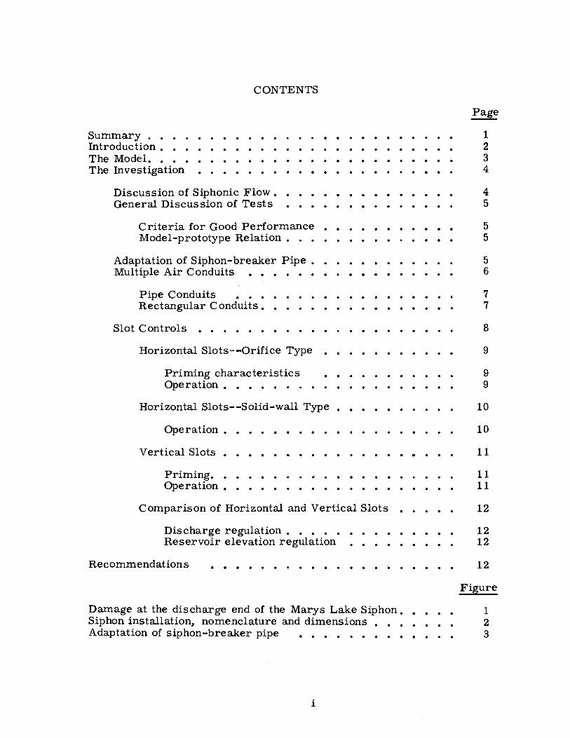
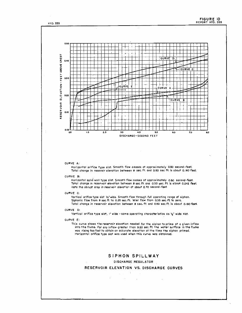
CURVE A:
Horizontal orifice type slot. Smooth flaw ceases at approximately 0.50 second-feet. Total change in resevoir elevation between 8 sec. ft. and 0.50 sec. ft is about 0.160 feet
CURVE B: Hor1zontol solid wall type slot. Smooth flow ceases at approximately 0.50 second-feet. Toto I change in reservoir elevation between a sec. ft. and a 50 sec. ft is a bout 0.242 feet Note the abrupt drop in reservoir elevation at about 2. 70 second-feet
CURVE C:
Vertical orifice type slot 1/z''wide. Smooth flow through full operoting range af siphon. Siphonic flow from 8 sec. ft to 0,35 sec. ft, Wier flow from 035 sec. ft to zero. Total change in reservoir elevation between e sec. ft and 0.50 sec. ft is about 0.190 feet
CURVE D:
Vertical orifice type slot, 1• wide -same operating characteristics as 1,2• wide slot
CURVE E:
This curve shows the reservoir elevation needed for the siphon to prime at a given inflow into the flume. Far any inflow greater than 3.20 sec. ft the water sulfoce in the flume was rising too fast to obtain on accurate elevation at the time the siphon primed. Horizontal orifice type slot was used when this curve was obtained.
SIPHON SPILLWAY DISGHARGE REGULATOR
RESERVOIR ELEVATION VS. DISCHARGE CURVES
_i.,..,
, ,_.,,·~ ~
8.0

FIGURE II · HYO .. 335
Reservoir elevation siphon discharging 8 c.f.ss-,
REPORT HYO, 335
• .. .>·· {:\ .• i:\''j:.' Crown--.,' !
El.t3.31"
~ ' ' I ' .. i : 5
7' =-IN
,·Original 4"x 6" opening _, partially filled to leave
a ~·x 6" opening.
SECTION A-A
i I
•' .,. ' ' I
~ ' ;,) 11!...IN
' ¼ I ' I ~---------6~-- ----->11" t<--------6~-------->1
k- - - -- - - - - ---- --- - --15~ -- - - -- - -- ---- - ----·>
SECTION B-B
SIPHON SPILLWAY DISCHARGE REGULATOR
SLOTTED OPENINGS
HORIZONTAL SOLID WALL TYPE
I I I
~ ui

HYO. 335 FIGURE 12
REPORT HYQ 335
Re~ervoir ~levatio~:~p:::ble sheet metal Pillot,,) ,,j~/·w·· > ...) .•• r•·• ·•f 00:x· D1scharg1ng 8c.f.s.----..) 11 , .::·-: :-:·.:_· •• :_.::·::::·:.:- • Crown- !
~===~==:_=_=_~_=_~_'=_=_~==~E~l-=+~4.§8=5 +~,:/'; ·-<_:{){ \> ~-:- ·. · · J r,,.~ ·::"_.-.·i."·Ef.+3.02" -~
=el~==::'._=_=_=_=:_=_ =.::::::~E-~-~1.(/ -- - 1 I I
Crest- El. o.oo _j_
SECTION A-A
;(Rem~~~~e sheet metal plates-r---., \ --- I J 111 ', /' I I JII \
\ ·i2r- ~ r ·>j r-2 ~ f_T __ ._ ----7 r-.-- ----, I I I I : I 1 l I I .: I I =..t I I 'r I I I I I : I I : I I I • I L_!. __ .._ ____ _j L_i___ _ ___ J
k--------6~------..l k------6 11-- _____ ,..J I I I I
--------------------1511 ------- ----------
SECTION B-B
SIPHON SPILL WAY DISCHARGE REGULATOR
SLOTTED OPENINGS
VERTICAL ORIFICE TYPE

Partially primed operation. Top photograph shows very little local draw-down aro\Uld slots. Water column at right edge of lower photograph shows reservoir elevation.
SIPHON REGULA TOR Vertical orifice-type slot Discharge - 1 second-foot
FIGURE 13 BYD 335

FIGURE 14 HYD 335
Slight water surface draw-down near slots. Lower photograph shows air-water mixture at about one-half maximum discharge. The air seems to be better distributed with this type of slot than with the horizontal slot, see Figure 8.
SIPHON REGULA TOR Vertical orifice-type slot Discharge - 4 second-feet
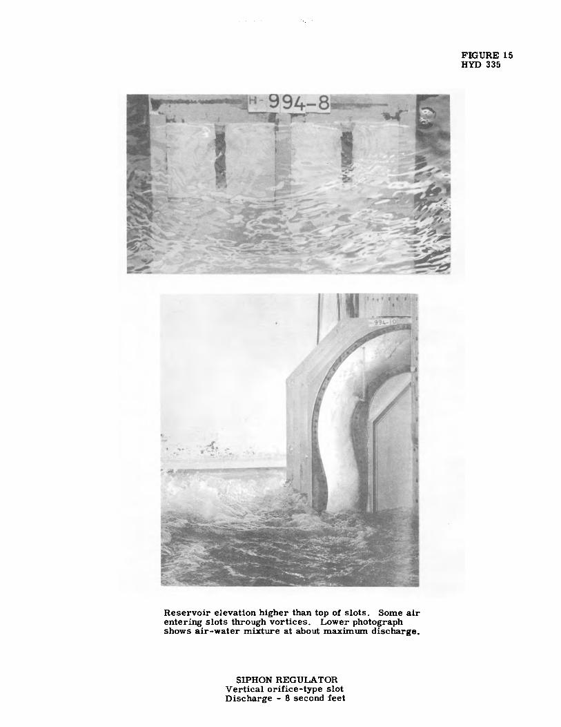
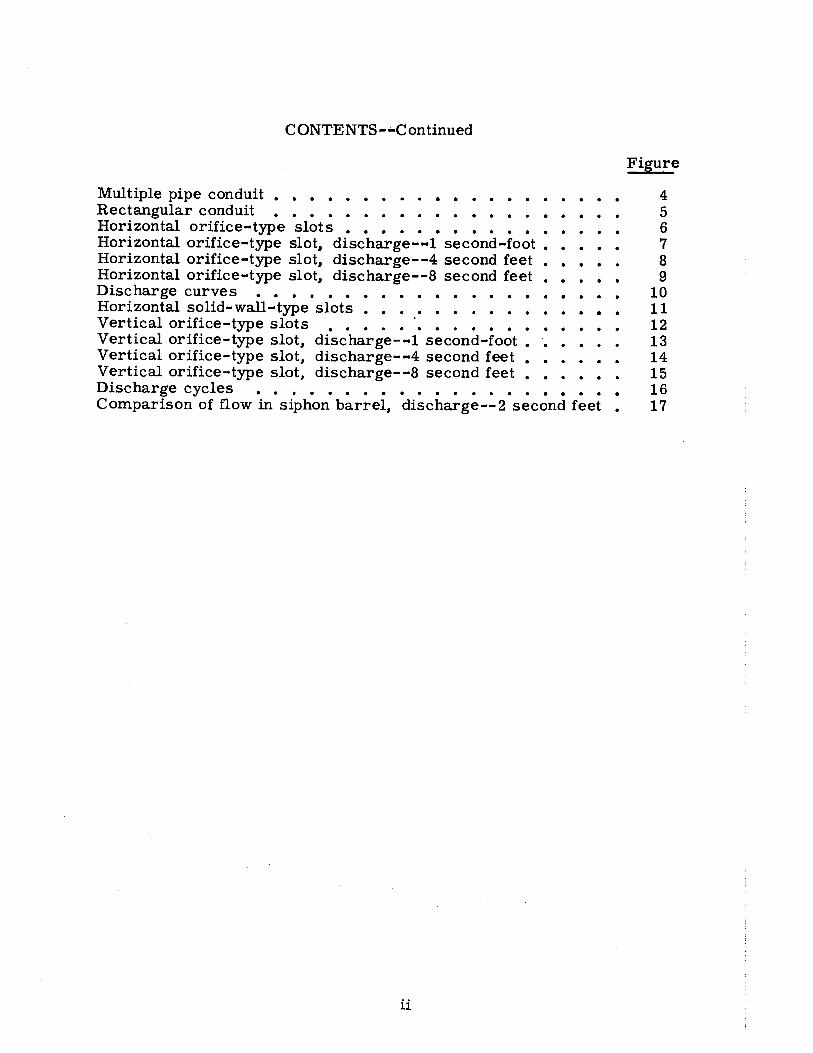
Reservoir elevation higher than top of slots. Some air entering slots through vortices. Lower photograph shows air-water mmure at about maximum discharge.
SIPHON REGULA TOR Vertical orifice-type slot Discharge - 8 second feet
FIGURE 15 HYD 335

HYO 335 FIGURE 16
REPORT HYO. 335
Iell ..,
0,50
a: 0.40 u .., >
i 1-
::: Q30 ... I
2 0 I-
"' ·> l&I Q20 ..J .., a: 0 > a: ::l QIO .., a:
j
I
A QOO
ao
J
J
'.'.'"n
J ·" ft ....... ,,M ~E
- >-:- -E'
) ·CURVI
J I
I
·---- --- -- ----L..,,
-- -- - -----·
1,0 2.0
I
L:--
1..,...-
i--, CURVE
I 3
,. -D
: _,__
3.0
DISCHARGE
, _i-
1..-,...
-- --
4.0 5.0
SECOND-FEET
1-i--,_ ..... _i,..,, • ··CURVE 4
:,, C -- ,__ --.........
CURVE 2
6.0 7.0
CURVE I CURVE 3
FREE FLOW DISCHARGE CURVE
CURVE 2
DISCHARGE CURVE- SIPHON WITH
HORIZONTAL ORIFICE TYPE SLOTS
PRIMING HEAD CURVE
CURVE 4
DISCHARGE CURVE - SIPHON WITH
VERTICAL ORIFICE TYPE SLOTS
I. For o. siphon equipped with horizontal or'ifice type slots, with on inflow of 3 second-feet. As the flow starts over the siphon crest the reservoir rises ond the dischorge increases
as shown by line A- B on the graph, when the reservoir elevation reaches B the siphon primes and the discharge instantaneously increases as shown by line B· C. The reservoir level then falls and the discharge decreases, as shown by line C-D,until the siphon is discharging 3 second-feet. The siphon will continue to poss 3 second-feet with o steady reservoir elevation as long as the inflow remains at 3 second-feet. If the inflow decreases to 0.50 second-feet the reservoir elevation and the discharge will decrease,as shown by line D-E,without breaking prime. For any increase in inflow the siphon discharge and the reservoir elevation will smoothly change along curve 2. Far an inflow less than 050 second-feet, say 030 second-feet, the reservoir elevation and discharge will increase as shown by line A-K, the siphon then primes and the discharge increases as shown by line K-L, the discharge and reservoir elevation then decrease as shown by line L·E', the siphon then breaks prime and the dischorge decreases from E' to M and the cycle M-K- L- E' repeats.
2. For o siphon equipped with vertical orifice type slots,with any inflow For an inflow the reservoir elevation and discharge increase along curve I to point o and then
along curve 4 until the discharge equals the inflow. The discharge and reservoir elevation remain steady· as long as the inflow stays the some, if the inflow increases or decreases the discharge and reservoir elevation smoothly change regardless of the quantity of inflow. The reservoir elevation-discharge relation always follows curve I up to point o and curve 4 for values greater than point o.
SIPHON SPILL WAY DISCHARGE REGULATOR
DISCHARGE CYCLES
i.--
~
8.0

G) 'U 0
"' to c,, I
IJ)
~
Vertical slot regulation Horizontal slot regulation
Discharge about one-fourth of maximum. Water column on right edge of each photograph shows the reservoir elevation. The air seems to enter the horizontal slots in slugs and the vertical slots steadily; howe.ver. notice the similarity of the air-water mixture in the lower leg of the siphon.
SIPHON REGULA TOR Comparison of flow in siphon barrel.
Discharge - 2 second-feet
= 1-zJ ~6
0 ~,:, ~t".1
.... -.:,