Embed Size (px)
Citation preview

Utah Underground Storage Tank (UST)
Groundwater & Soil Sampling Reference Material
August 2011
www.undergroundtanks.utah.gov

INDEX UST Branch: Program Overview. Section 1: Sampling Procedures
• Sampling Procedures and Requirements For Underground Stogage Tank (UST) Sites • Subsurface Investigations, Sampling & Analytical Requirements (Chapter 6 - Consultant
Certification Manual 2009) • EPA-RCRA Ground-Water Technical Enforcement Guidance Document – Chapter 4
(September 1986) • Compendium of ERT Surface Water and Sediment Sampling Procedures (January 1991) • Closure Plan Requirements • UST Closure Plan • UST Closure Notice • Other DEQ Division Requirements • Site Assessment and Mitigation Manual – Section 5(III)
http://www.co.san-diego.ca.us/deh/water/sam_manual.html Section 2: Cleanup Standards
• Initial Screening Levels (ISLs) • Analytical Methods for Environmental Sampling at Underground Storage Tank Sites in
Utah • Screening /Cleanup Levels for LUST Sites (Chapter 7 - Consultant Certification Manual
2009) • Leaking Underground Storage Tanks (LUST) Subsurface Investigation Report (SIR)
Guide • Guidelines for Disposition and Treatment of Petroleum Contaminated Soils For
Underground Storage Tank Sites Section 3: Health & Safety
• General Site Health and Safety (Chapter 5 - Consultant Certification Manual 2009) • Health and Safety Training for Underground Storage Tank Inspector (Partial - June 1992)
Rules and Regulation: see UST Certification Requirements and Rules http://www.undergroundtanks.utah.gov/study_guides.htm

UST Branch: Program Overview
The Utah State Underground Storage Tank program is a regulatory branch of the Department of Environmental Quality. Its primary goal is to protect human health and the environment from leaking underground storage tanks (USTs). The UST staff oversees: UST notification, installation, inspection, removal, and compliance with State and Federal UST regulations concerning release prevention and remediation.
What are Underground Storage Tanks?
An UST is a tank system, including piping connected to the tank, that has at least 10 percent of its volume underground. Federal and state regulations apply only to those USTs containing petroleum products or certain hazardous chemicals. USTs not regulated include:
• Farm or residential tanks 1,100 gallons or less, used non-commercially. • Tanks storing heating oil, used on the premises. • Flow-through process tanks. • Emergency spill and overflow tanks. • Tanks holding 110 gallons or less. • Others as described in the federal register.
Why Worry About An UST Release?
Utah obtains more than 50% of the population's drinking water from groundwater. Currently, there are more than 3000 leaking UST sites in Utah. These sites have resulted in contaminated ground water and in some cases, explosive situations. Many more USTs in Utah could leak or have yet to be discovered in the future adding to the existing problems.
What Do the UST Regulations Accomplish?
The Environmental Protection Agency (EPA), with the help of the regulated industry, developed regulations concerning UST owners and operators. The goals of these regulations include:
• To prevent leaks and spills. • To find leaks and spills. • To correct the problems created by leaks and spills. • To ensure the owners and operators can pay for clean-up associated with
leaking USTs. • To ensure that Utah has a regulatory program that complies with the
Federal regulations.

The EPA phased-in many of the requirements over a ten year period beginning December 22, 1988. By December 22, 1998, all operating facilities were required to be upgraded with corrosion protection, spill and overfill equipment, and regularly monitored for a release. Non-operational facilities must be properly closed..
The Utah UST Program
As a result of the federal mandate, the State of Utah amended the Solid and Hazardous Waste Act in 1986 which established the Utah UST Program. UST owners and operators were required to register all USTs. In 1989, the Underground Storage Tank Act was enacted; it details the duties and responsibilities of the Executive Secretary (UST), the Solid and Hazardous Waste Control Board, and the Utah UST Program Authority. The act established the Petroleum Storage Tank (PST) Fund and provides certain requirements for UST owners and operators.
Executive Secretary (UST)
The Executive Secretary (UST) is an individual who has the authority to administer the UST Program as established by the Utah Legislature. The Executive Secretary answers to the Utah Solid and Hazardous Waste Control Board which consists of approximately ten individuals appointed by the Governor.
The UST Section
The UST section of the Division of Environmental Response and Remediation (DERR), is a group of environmental scientists whose task is to oversee the regulated public in issues that concern the operational life of USTs up to proper closing of UST systems. The UST staff has tracked about 15,000 USTs and currently regulates approximately 4,300 USTs at more than 1,500 different facilities. UST staff members perform compliance inspections, issue compliance notices, and serve as expert witnesses at administrative hearings. Outreach classes and seminars are taught throughout the state.

The LUST Section
The Leaking Underground Storage Tank (LUST) section of DERR oversees remediation of contamination from USTs. LUST scientists and engineers review and reestablish clean-up guidelines. When responsible parties are not available or are unable to pay for the remediation of a LUST site, the LUST staff is required to define the degree of hazard, possibly take action with LUST-TRUST money to abate the hazard and remediate the site, and recover costs incurred from responsible parties. Often, responsible parties seek the guidance of the LUST staff to insure clean-up in a timely and economical fashion.
Administrative Support Section
The administrative support section oversees collection of UST fees and monitors expenditures. Accountants and technicians answer questions concerning billings and distribute funds where appropriate.
What are the Requirements for Owner/Operators of Underground Storage Tank Systems?
• Notify the DERR of all regulated USTs with EPA Notification Form 7530-1. • Pay any applicable fees. • Obtain a Certificate of Compliance. • Maintain compliance with regulations. • Upgrade USTs when required. • Report any UST release to the DERR. • Remediate contamination. • Remove UST appropriately.
Comments and Questions
You can obtain more information and forms from the DERR, 195 North 1950 West, Salt Lake City, Utah 84116; phone 801-536-4100.

Sampling Procedures

Sampling Procedures and Requirements for Underground Storage Tank (UST) Sites
The below-listed items assist to ensure that all types of samples collected are of good integrity, representative of environmental conditions, and provide legally defensible data.
1. Describe and document any necessary property access requirements.
2. All soil, groundwater, and surface water samples must be collected by a Utah certified sampler. The name and certification number of the sampler must be clearly identified.
3. All soil, groundwater, and surface water samples must be analyzed by a Utah certified laboratory. The name of the analytical laboratory must be clearly identified.
4. Native soil type must be evaluated using Unified Soil Classification methods. Other detailed lithologic descriptions may also be necessary.
5. Describe subsurface stratigraphy and continuity of strata beneath the site. Describe features such as discontinuous clay, silt, or sand lenses, interbedded strata, and other features.
6 . Chain of Custody documentation must be maintained and provided for all samples collected.
7. Identify sampled media (soil, groundwater, surface water, drinking water, air, other) and ensure that the identification for each sampled media is consistent.
8. All sample identifications, names and numbers must be consistent throughout the Chain of Custody documentation, laboratory analytical results, site map, data tables, and the report text.
9. Describe the rationale for selecting sample locations and sampled intervals in excavations, test pits, soiVwel1 borings, soil land farms, soil stockpiles, or other sample locations. Describe whether the sample location determination was based on field instrument measurements, random selection, judgmental or other reasons.
10. Describe and/or illustrate depths at which samples are collected.
1 1. Show sample locations on a properly scaled and oriented site map.
12. Specify the following sampled features and the applicable media sampled, including but not limited to: a. Excavations b. Test pits c. Soil borings d. Soil borings for wells e. Soil land farms

f. Soil stockpiles g. Wells, including vadose injection and extraction, groundwater monitor, groundwater
injection and extraction or other. h. Piezometer I . Surface water
13. Identify the sample type(s) including, but not limited to, the following: a. Grab b. Composite c. Headspace d. Time-flow averaged e. Closure sample f. Confirmation sample (verification) g. Quality control (QC) samples (duplicates, splits, blanks, etc).
14. Provide detailed descriptions of field screening methods and devices used, including but not limited to organic vapor meters, or other methods for detecting the presence of vapor contamination.
15. Describe sampling methodology, equipment and devices used.
16. Describe devices used to measure the depth to groundwater.
17. Describe the proper Q N Q C sample collection methods and equipment used. a. Describe sample containers for each sample type and media, and identify the source
or supplier of the sample containers. b. Describe decontamination procedures for all sampling equipment, containers, water
and product level measuring devices, drilling equipment, or other devices that contact and affect the sample.
c. Sampling procedures must be conducted in a manner that minimizes the loss of volatile organic compounds. Describe the methods used to minimize the loss of volatiles and maintain sample integrity, including but not limited to the following: Zero headspace in sample container, methods used to preserve the sample at 4" Celsius (approximately 39.2" Fahrenheit).
d. Describe methods used to transport environmental samples to the laboratory. e. If samples are not immediately delivered to the laboratory, describe the methods used
to preserve samples and maintain sample integrity. f. Describe how groundwater wells were purged and the calculations that support the
reported number of casing or borehole volumes removed. Purging is complete when the pH, electrical conductivity, and temperature stabilize. If following this procedure is not possible, remove a minimum of three volumes.
18. If a health and safety plan was prepared for the site, please submit a copy.

19. Analytical Methods and Contamination Concentration Determination: The following chart shows the constituents in each product type that must be analyzed using suggested analytical methods. The analyses of additional constituents may be required, as determined by the
Substance or Product Type
Gasoline
Diesel
Used Oil
New Oil
Other or Unknown
ve Secretary.
Contaminant Compounds to be Analyzed I ANALYTICAL METHODS'
I Soil, Groundwater (Table of Analytical Methods for Sampling March 3 1, 1999) or Surface Water
Oil and Grease (O&G) or Total Recoverable Petroleum I EPA 1664 or 5520 Hydrocarbons (TRPH)
Total Petroleum Hydrocarbons (TPH); and Benzene, Toluene, Ethyl benzene, Xylenes, Naphthalene, (BTEXN) and MTBE
Total Petroleum Hydrocarbons (TPH); and Benzene, Toluene, Ethyl benzene, Xylenes, and Naphthalene (BTEXN)
Oil and Grease (O&G) or Total Recoverable Petroleum Hydrocarbons (TRPH); and Benzene, Toluene, Ethyl benzene, Xylenes, Naphthalene (BTEXN) and MTBE; Halogenated Volatile Organic Compounds (VOC's)
EPA 801 5B' and EPA 802 1 B' or 8260B
EPA 801 5B and EPA 802 1 B or 8260B
EPA 1664 or 5520' and EPA 802 l B or 8260B
Halogenated Volatile Organic Compounds (VOC's)
Total Petroleum Hydrocarbons (TPH); and Benzene, Toluene, Ethyl benzene, Xylenes, and Naphthalene (BTEXN);
'The following modifications to thesse certified methods are considered acceptable by the Executive Secretary (UST): A. Dual column confirmation may not be required for TPH & BTEXNIMTBE analysis. B. A micro-extraction or scale-down technique may be used for aqueous samples. C. Hexane may be used as an extraction solvent. Note: The sample preparation method and any modification(s) to a certified method must be reported by the
laboratory on the final analytical report. ' Methods or test procedures allowed for Oil and Grease (O&G) or Total Recoverable Petroleum Hydrocarbons (TRPH) are 5520(b) or 5520(f) respectively. * When sampling a known substance, analyze for that substance, i.e anti-freeze tank analyze for ethylene glycol.
EPA 801 5B and EPA 802 1 B or 8260B
20. Laboratory analytical detection limits must be sufficiently low in order to detect contaminant concentrations at or below their applicable maximum contaminant levels or state-established cleanup levels.
21. Submit copies of original laboratory report forms; must include detection levels.
22. If soil samples are corrected for moisture content, please provide the moisture content of the sample and any other relevant information.
23. Ensure that dates of sample collection, date submitted to the laboratory, and date analyzed are clearly identified in all submitted reports and information.
24. Groundwater well installation and abandonment must be conducted in accordance with the Utah Division of Water Rights specifications.

If soil borings and wells are emplaced, the following information at a minimum is required: 1 . Type of drilling apparatus and equipment. 2. Drilling fluids used, if applicable. 3. Appropriate vertical scale must be shown on the boring logs. 4. Detailed geologic boring logs describing the lithology, grain sizes, grain angularity,
sorting, color, moisture, firmness, plasticity, strata characteristics such as bed thickness, lenses, interbedding, or other pertinent features.
5 . Sample collection locations, including soil, groundwater, and organic vapor meter measurements, headspace, or other.
6. Blow counts per foot, if applicable. 7 . Presence or absence of hydrocarbon staining. 8. Depth to groundwater, if encountered, and groundwater elevations. 9. Total depth of well or boring. 10. Number of wells and/or borings. 1 1. As-built drawings. 12. Well construction materials, including casing screen type, filter pack material and
particle size. 13. Screen length and slot size. 14. Type and placement of pumps, if applicable.
26. Describe in detail the procedures used to dispose of drill cuttings, purged water, or any other materials generated during any phase of work.

Environmental Sampling
INTRODUCTION
Investigations at UST sites usually require chemical and physical analyses of soil and groundwater samples that were collected at the sites. The data obtained serve as the basis for decisions regarding impacts to soil and potential drinking water supplies, and assessing actual and potential impacts to human health and the environment. Data obtained on soil and groundwater quality at UST sites must, to the greatest extent possible, be accurate and representative of site conditions. This chapter reviews environmental sampling with emphasis on those techniques and pertinent items discussed in the Certified Samplers Training and is customized to DERR rules and regulations.
REGULATIONS
Field operations involving environmental sampling at underground storage tank sites in the state of Utah shall conform to all rules and regulations set forth in 40 CFR Part 280 Subparts: A,B,C,D,E,F and G ; and in State of Utah Administrative Code (UAC): R311, Parts 200-208. Additionally, a State of Utah Closure Plan conforming to UAC R311-204 must be submitted outlining details of the UST system closure. Soil and groundwater samples must be collected by a State of Utah Certified Soil and Groundwater Sampler during closure operations and during subsequent field investigations.
Following the UST closure, the OwnerIOperator (010) must submit a completed "Closure Notice" to the DERR UST section to document that the closure was performed as outlined in the Closure Plan.
SAMPLING EQUIPMENT AND TECHNIQUES
Sampling equipment and techniques must conform to the State's Site Assessment Protocol. A brief summary of protocol guidelines follows.
Sample Types
In addition to the environmental and USC samples required at UST sites, as discussed above, state regulations stipulate that grab samples be collected rather than composite samples. If groundwater is encountered at a site, water samples are to be collected in the same sampling locations as soil samples, but 6-inches below the top of the water level.
State of Utah regulations require that two types of samples be collected during closure at all UST sites in the State:
Environmental samples, which are soil andlor groundwater samples, which are analyzed for petroleum constituents. Environmental samples must be analyzed by a State of Utah certified laboratory. Uniform soil classification (UST) samples which are analyzed for soil type.

Environmental samples must be collected during subsurface investigations and after corrective actions at LUST sites. USC samples are not required during these phases, if USC samples were collected during UST closure.
UST Closure Sampling Locations
Sampling locations depend upon the number of tanks at the site and whether or not groundwater is encountered during excavation. Generally, at a &k site, and if no groundwater is encountered, two environmental soil samples must be collecte 9 at each end of the tank, 0-2 feet below native soil- tank backfill interface. If groundwater is encountered, a minimum of one groundwater sample and one soil sampled must be collected at each end of the excavation. One USC soil sample must be collected at the same depth as the environmental sample. If two or more tanks are in the same excavation, and if no groundwater is encountered, four environmental soil samples must be collected, one from each corner of the excavation, 0-2 feet below native soil-tank backfill interface. If groundwater is encountered, a minimum of one groundwater sample and one soil sample must be collected at each end of the excavation. One USC soil sample must be collected at the same depth as the environmental sample. Re& RJ 11 - W
Subsurface Investigation Sampling Locations
Soil borings and monitoring wells are installed as part of the subsurface investigation at a LUST site to delineate the lateral and vertical extent of contamination. A decision on the locations and number of soil borings and monitoring wells should be made in consultation with the DERR project manager, and should be determined based on site-specific information. At some sites three or four soil borings may be enough to delineate the extent of contamination, while at other sites a dozen or more soil borings may be needed. Soil or rock samples should be collected for potential laboratory analysis. A minimum of one soil sample should be analyzed from each soil boring, regardless of depth of the boring. Several soil samples should be analyzed from deep soil borings. A sufficient number of soil samples from each soil boring should be analyzed to determine the vertical extent of contamination in the boring.
Groundwater monitoring wells are required at sites where groundwater is impacted. A minimum of three groundwater monitoring wells are necessary to define the groundwater flow direction. In practice, more than three wells are typically necessary so that at least one monitoring well is directly down gradient from the source of the contamination. A down gradient monitoring well is helpful to demonstrate if contamination remains onsite or has migrated offsite. Conversely, an upgrading well is helpful to demonstrate if contamination is moving onto the site from an offsite source.
Corrective Action Confirmation Sampling Locations
Corrective action confirmation samples are environmental samples that are collected to demonstrate that cleanup goals have been achieved after corrective action at site is complete. The number and locations of samples should be determined in consultation with the DERR project manager, and are based on site-specific information. By way of example:

• at least one soil sample should be collected and analyzed from each sidewall and bottom of an excavation pit after over excavation is complete
groundwater samples should be collected from each monitoring well at a site after groundwater remediation is complete
PIDfFID Monitoring
Photoionization detector (PID) and Flame ionization detector (FID) instruments are the most common hydrocarbon vapor analyzers in use. Their use serves two purposes: protection of worker health; and screening of environmental samples to determine which samples to analyze and the relative concentrations of hydrocarbons that the sample may contain.
Soil Sampling
Clean and decontaminated stainless steel spoons, trowels, hand augers, or split-spoon sampler should be used to collect soil samples. Excavate, or hand auger, the natural soil until the correct location and depth are reached as required in the State Site Assessment Protocol. The sample container should be full with no air or head space between the soil and the cap. All samples should be shipped to the laboratory as soon as possible to ensure quality. The maximum time between sample collection and analysis is 14 days.
Groundwater Sampling
Groundwater samples are typically collected with a bailer. The bailer should be lowered into the water slowly allowing only the top portion of the water, near the surface, to be sampled. The sample should be sufficient to fill the sampling container. No air should be allowed between the liquid surface and the lid of the container. It is important not to shake or agitate the sample in the bailer as this might cause the loss of volatiles (BTEX).
Prior to water being sampled from a monitoring well, the must be measured and the total water volume calculated. A minimum of 3 should be removed to ensure that all stagnant water has been replaced by fresh formation water. If free product is suspected or verified during water level measurements, an interface probe, or hydrocarbon sensitive paste should be used to measure the apparent thickness of the free product.
Analytical Methods
Soil and groundwater environmental samples are analyzed for petroleum constituents as follows:
• Total petroleum hydrocarbons (TPH) as gasoline andfor diesel (based on contents of the USTs) using 8015B. If the USTs contained oil or used oil, total recoverable hydrocarbons (TRH) using U.S. EPA Method 5520 or oil and grease (O&G) using U.S. EPA Method 1664 are substituted for the TPH analyses.
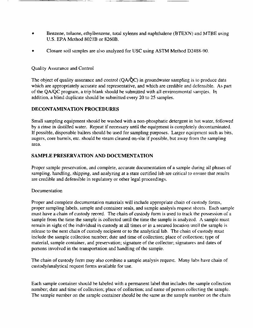
Benzene, toluene, ethylbenzene, total xylenes and naphthalene (BTEXN) and MTBE using U.S. EPA Method 8021B or 8260B.
Closure soil samples are also analyzed for USC using ASTM Method D2488-90.
Quality Assurance and Control
The object of quality assurance and control ( Q N ~ C ) in groundwater sampling is to produce data which are appropriately accurate and representative, and which are credible and defensible. As part of the QAIQC program, a trip blank should be submitted with all environmental samples. In addition, a blind duplicate should be submitted every 20 to 25 samples.
DECONTAMINATION PROCEDURES
Small sampling equipment should be washed with a non-phosphatic detergent in hot water, followed by a rinse in distilled water. Repeat if necessary until the equipment is completely decontaminated. If possible, disposable bailers should be used for sampling purposes. Larger equipment such as bits, augers, core barrels, etc. should be steam cleaned on-site if possible, but away from the sampling area.
SAMPLE PRESERVATION AND DOCUMENTATION
Proper sample preservation, and complete, accurate documentation of a sample during all phases of sampling, handling, shipping, and analyzing at a state certified lab are critical to ensure that results are credible and defensible in regulatory or other legal proceedings.
Documentation
Proper and complete documentation materials will include appropriate chain of custody forms, proper sampling labels, sample and container seals, and sample analysis request sheets. Each sample must have a chain of custody record. The chain of custody form is used to track the possession of a sample from the time the sample is collected until the time the sample is analyzed. A sample must remain in sight of the individual in custody at all times or in a secured location until the sample is release to the next chain of custody recipient or to the analytical lab. The chain of custody must include the sample collection number; date and time of collection; place of collection; type of material, sample container, and preservation; signature of the collector; signatures and dates of persons involved in the transportation and handling of the sample.
The chain of custody form may also combine a sample analysis request. Many labs have chain of custody/analytical request forms available for use.
Each sample container should be labeled with a permanent label that includes the sample collection number; date and time of collection; place of collection; and name of person collecting the sample. The sample number on the sample container should be the same as the sample number on the chain

of custody form. Waterproof or indelible ink should be used to write on the sample labels.
Coordination with a Certified Laboratory
The sampler should contact a state Certified Lab in advance of sampling to determine that the lab is capable of conducting the sample analysis within the specified holding time, usually 14 calendar days. For oil and grease samples, the time is 28 calendar days. The State Certified Lab must use an approved detection method that will detect levels for BTEXN in water at 5 ug/L, or lower.
The USC sample may be described by a qualified geologist in the field, or analyzed by a certified lab or a geotechnical lab.
Preservation and Shipping Procedures
Soil and groundwater samples should be placed in a container acceptable by both the lab and carrier, if the samples are not going to be transported directly to the lab by the sampler or representative. Dry ice should not be used when shipping water samples as the samples may freeze and break the glass container. Additionally, when shipping samples of pure volatile like gasoline, never fill the container to the top, as expansion during transportation may rupture the glass container.
SAFETY
Personal safety is paramount at UST sites. Petroleum products are toxic and present fire and explosion hazards. Personal safety in the collection of soil and groundwater samples at UST facilities must meet the standards required by federal and state regulatory agencies.
Extreme care should be used when it becomes necessary to enter an excavation for sampling purposes. If this is the case, the excavation side walls should be sloped or shored to prevent slumping or cave-in.

Subsurface Investigation, Sampling, and Analytical Requirements
6-1
Utah Division of Environmental Response and Remediation Underground Storage Tank Consultant Certification Manual 2009
CHAPTER 6 Subsurface Investigations, Sampling, and Analytical Requirements
Requirements and format guidelines for Subsurface Investigation Reports are presented in the LUST Subsurface Investigation Report Guide (Chapter 3). In accordance with Utah UST Rule R311-201-2 (Chapter 1), leaking underground storage tank (LUST)-related work must be overseen by a Utah-Certified UST Consultant in the event the owner/operator does not conduct and manage the investigative and cleanup work in house. Soil and groundwater sampling must be performed by a Utah-Certified Groundwater and Soil Sampler. 6.1 EXPEDITED SITE ASSESSMENT___________________________________________ An expedited site assessment (ESA) is a process of rapidly delineating the extent of soil and groundwater contamination, determining potential exposure pathways, and identifying potential receptors at LUST sites. An ESA utilizes rapid soil sampling methods (direct-push hydraulic borehole rigs), installation of small diameter groundwater monitoring wells (1 to 2 inch diameter), on-site surveying and determination of groundwater flow direction, field analytical methods (mobile laboratories), and on-site decision-making by experienced personnel. The goal of an ESA is to complete a subsurface investigation in one mobilization. Conventional site assessment processes can involve several mobilizations because decisions regarding the placement of additional soil boreholes or monitor wells are usually made back in the office following data evaluation. The field work is usually conducted by less experienced field technicians who collect samples for off-site laboratory analysis. For more detailed information on ESAs, the reader should review the U.S. EPA’s guidance document entitled Expedited Site Assessment Tools For Underground Storage Tank Sites (EPA, 1997). 6.2 BACKGROUND RESEARCH_______________________________________________ Before conducting a subsurface investigation at a LUST site, background research on the current and historical uses of the site and surrounding area should be performed. The following examples illustrate the usefulness of this information. ♦ Review DERR Interactive Map to find information on other LUST sites within the vicinity of
the subject LUST site. These files can provide information on soil types, depth to groundwater, and groundwater flow direction. This information can be used to determine the type of drilling rig to use and how deep monitor wells must be installed.
♦ Review Utah Division of Water Rights (DWR) records. These records can provide
information on the presence of municipal, domestic, irrigation, and other types of water wells in the area. In some cases, geologic borehole logs and well construction information are available online as well.
♦ Review historical aerial photographs. This information can be used to determine past uses of
the site and surrounding area. For example, aerial photographs can be used to determine if other USTs are/were located on the site.

Subsurface Investigation, Sampling, and Analytical Requirements
6-2
Utah Division of Environmental Response and Remediation Underground Storage Tank Consultant Certification Manual 2009
CHAPTER 6 Subsurface Investigations, Sampling, and Analytical Requirements
6.3 SITE RECONNAISSANCE__________________________________________________ Prior to performing a subsurface investigation, a reconnaissance of the site and surrounding area should be conducted. Information to be obtained includes: ♦ The locations of all USTs, product piping, and pump islands. ♦ The locations of all other potential sources of environmental contamination, such as septic
tanks, leach fields, and floor drains. ♦ The locations of all wells on site or in the vicinity of the site. Verify the presence and use of
all wells identified by the DWR records search. ♦ The locations of overhead and underground utilities for drilling safety purposes and potential
contaminant transport. “Blue Stakes” can be called to mark out the site prior to your site visit (Chapter 9).
♦ The locations and addresses of businesses and property owners in the vicinity for access
agreements and potential environmental concerns. ♦ Photographs of the site and vicinity. Using the information collected during the site reconnaissance, prepare scaled site and vicinity maps. 6.4 SUBSURFACE INVESTIGATION___________________________________________ The following sections describe several types of techniques used for traditional and expedited subsurface investigations. 6.5 SOIL AND GROUNDWATER SAMPLING____________________________________ The following section describes the various types and locations of soil and groundwater samples collected at UST sites in Utah. 6.5.1 Sample Types Utah UST regulations require that the following types of samples be collected at UST closure: ♦ Environmental samples: Soil and groundwater samples collected for laboratory analysis
for petroleum hydrocarbon compounds by a Utah-certified analytical laboratory. Soil and water samples must be discrete, not composites.

Subsurface Investigation, Sampling, and Analytical Requirements
6-3
Utah Division of Environmental Response and Remediation Underground Storage Tank Consultant Certification Manual 2009
CHAPTER 6 Subsurface Investigations, Sampling, and Analytical Requirements
♦ Unified Soil Classification System (USCS) samples: Soil samples analyzed for soil type.
USCS samples may be described by a qualified geologist in the field or analyzed by a Utah-certified analytical laboratory or a geotechnical laboratory. Information on field soil classification is included in the section below on Soil Classification.
♦ Environmental confirmation samples are collected during an UST closure if
overexcavation has removed additional soil past the location of the closure samples. USCS samples are not required during this and later phases, if USCS samples were collected during UST closure. However, detailed descriptions of subsurface lithology are required during the subsurface investigation phase in order to determine contaminant migration potential and select a remediation methodology.
Requirements for sampling of soil and groundwater at UST closures are detailed in Utah Underground Storage Tank Rule R311-205-2(b). The UST Rules are referenced in Chapter 1. 6.5.2 Subsurface Investigation Sampling Soil boreholes and monitoring wells are installed as part of a subsurface investigation at a LUST site to delineate the lateral and vertical extent of contamination. Decisions regarding the number and locations of soil boreholes and monitoring wells should be made in consultation with the DERR Project Manager. For example, at some sites three or four soil boreholes may be enough to delineate the extent of contamination. At other sites a dozen or more soil boreholes may be needed. A minimum of one soil sample should be analyzed from each soil borehole, regardless of the depth of the borehole. Several soil samples should be analyzed from deep soil boreholes. A sufficient number of soil samples from each soil borehole should be analyzed to determine the vertical extent of contamination in the borehole and document the lithology. It may be necessary to collect soil samples below the water table to fully delineate the vertical extent of contamination. Instruments with photoionization and flame-ionization detectors (PID/FID) are commonly used in the field to monitor ambient air for the protection of worker health and qualitatively determine relative volatile petroleum hydrocarbon vapor concentrations in soil samples. These instruments are used to screen soil samples to determine which samples to analyze in an off-site Utah-certified analytical laboratory. Groundwater monitoring wells are required at sites where groundwater is encountered. A minimum of three groundwater monitoring wells are necessary to determine the groundwater flow direction and gradient. In practice, more than three wells are typically necessary so that at least one monitoring well is located directly downgradient of the source of the contamination. A downgradient monitoring well is required to determine if contamination has migrated off site. Conversely, an upgradient well is useful to determine if contamination is migrating onto the site from an off-site source.
Subsurface Investigation, Sampling, and Analytical Requirements
6-4
Utah Division of Environmental Response and Remediation Underground Storage Tank Consultant Certification Manual 2009
CHAPTER 6 Subsurface Investigations, Sampling, and Analytical Requirements
6.5.3 Corrective Action Confirmation Samples Corrective action confirmation samples are environmental samples that are collected to demonstrate that cleanup goals have been achieved after corrective action at site is complete. The number and locations of samples should be determined in consultation with the DERR Project Manager. For example: ♦ Soil samples should be collected and analyzed from each sidewall and the bottom of an
excavation pit after overexcavation of contaminated soil is complete. ♦ Groundwater samples should be collected from each monitoring well at a site after
groundwater remediation is complete. ♦ Post remedial soil confirmation samples must indicate that contaminant concentrations in
soil meet cleanup goals following in-situ remediation as well. These soil samples should be collected from each location where cleanup standards were exceeded during site investigation.
6.5.4 Soil Classification In general, soil classification systems are used to describe soil particle-size distribution, or texture that affects hydrologic, engineering, and contaminant transport characteristics of the soil. The most common classification system utilized in classifying soils using their engineering properties is the USCS. Other classification systems not described in this manual may be better suited to interpret depositional environments and hydrologic and contaminant transport properties. The American Society for Testing and Materials (ASTM) has developed a Standard Practice for Description and Identification of Soil (Visual-Manual Procedure) D2488-93, which describes the description of soils for engineering purposes using the USCS. Relative proportions of grain size are estimated either in the laboratory or field. The USCS also incorporates other soil properties such as plasticity, liquid limit, clod strength, dilatancy, toughness, and stickiness for classification.

Subsurface Investigation, Sampling, and Analytical Requirements
6-75
Utah Division of Environmental Response and Remediation Underground Storage Tank Consultant Certification Manual 2009
CHAPTER 6 Subsurface Investigations, Sampling, and Analytical Requirements
6.38 GROUNDWATER SAMPLING AND HANDLING PROCEDURES______________ This section provides an overview of groundwater sampling and handling procedures, which generally are applicable to any groundwater monitoring program. This section is not intended to provide specific guidance on sampling for a specific situation, but provides information on the major activities that are required for sample collection and handling. The starting point for any groundwater sampling program is the quality assurance/quality control (QA/QC) plan. Groundwater sampling protocols appropriate to the data quality objectives and the site conditions will define the specific procedures that will be followed for individual sampling events. Well purging typically has been an important element of sampling procedures, the specific procedures of which will vary with site conditions. Specific sample handling and preservation procedures are likely to vary somewhat, depending on the analyte of interest at a site, as will decontamination procedures.
6.39 LUST SITE GROUNDWATER MONITORING WELL PURGING_______________ Prior to collecting groundwater samples from a monitoring well, stagnant water must be removed from the well. This is called “well purging.” A minimum of three well volumes of water should be removed to ensure that all stagnant water has been replaced by representative formation water. If free product is detected during water level measurements, an interface probe or hydrocarbon-sensitive paste should be used to measure the apparent thickness of the LNAPL. The following section excerpted from Subsurface Characterization and Monitoring Techniques (EPA, 1993b) describes well purging methods, considerations, and frequency of use. 6.40 LUST SITE GROUNDWATER SAMPLING__________________________________ Following purging, groundwater samples are typically collected from monitoring wells with a bailer. The bailer should be lowered into the water slowly, allowing only the top portion of the water nearest the air-water interface to be sampled. For volatile petroleum hydrocarbon compounds, such as TPH, BTEX, and MTBE, the groundwater sample should be poured from the bailer into volatile organic analysis (VOA) vials. After filling, no air bubbles (no headspace) should be present in the VOA vials. Groundwater may also be collected with a low-flow pump to minimize aeration of the sample.

Subsurface Investigation, Sampling, and Analytical Requirements
6-76
Utah Division of Environmental Response and Remediation Underground Storage Tank Consultant Certification Manual 2009
CHAPTER 6 Subsurface Investigations, Sampling, and Analytical Requirements
6.41 WELL PURGING_________________________________________________________ 6.41.1 Other Names Used to Describe Method Well flushing. 6.41.2 Uses at Contaminated Sites Removing stagnant water from a well before sample collection. 6.41.3 Method Description Well purging involves the pumping of stagnant water from a well before sample collection. A monitoring well is pumped (generally at a rate from 1 to 5 gallons per minute) until a certain number of well volumes have been removed and until water quality indicators, such as pH, conductance and/or temperature, have stabilized, indicating that fresh formation water fills the well. Sampling takes place after purging is completed. Recent research (Kearl et al, 1992) has suggested that purging is not desirable because it can mobilize colloidal particles upon which contaminants are sorbed. The alternative to purging is to use a dedicated sampling device set at the level of the well screen capable of low pumping rates (around 100 mI./minute), which will not increase colloid density in the ground-water sample compared to natural colloidal flow through the well. 6.41.4 Method Selection Considerations Recommended rules of thumb, such as purging three to five volumes (Fenn et al., 1977) should be treated only as a starting point. Accurate estimation of purge volume requires knowing: (1) Well yield, determined from a slug or pumping test, and (2) the stagnant volumes of both the well casing and the sand pack. Figure B.2a shows the volume of water stored per foot of well casing at different diameters. In slowly recovering wells, extra care is required when purging to ensure that water levels do not drop below the level of the well screen because aeration might allow loss of volatile or redox sensitive contaminants. After stagnant water has been removed or isolated, chemical indicators (pH, conductance, and temperature) should continue to be monitored until they reach a consistent end point (no upward or downward trend). Another important consideration in purging is that the pumping rate should not exceed levels that will cause turbulent flow. Turbulent flow in the well might cause pressure changes, which could result in loss of carbon dioxide and other volatile gases, subsequently changing pH and dissolved solids content (Meredith and Brine, 1992). The maximum discharge rate during pumping that avoids turbulent flow is a function of hydraulic conductivity, the length of the well screen, width of the screen openings, and the total open area of the screen. Figure B.2b shows the optimum screen entrance velocity related to the hydraulic conductivity of an aquifer. Table B2 provides guidelines for maximum purging rate based on screen type, diameter, slot size, open area, and entrance velocity (from Figure B.2b).

Subsurface Investigation, Sampling, and Analytical Requirements
6-77
Utah Division of Environmental Response and Remediation Underground Storage Tank Consultant Certification Manual 2009
CHAPTER 6 Subsurface Investigations, Sampling, and Analytical Requirements
6.41.5 Frequency of Use Has been a standard procedure for all ground-water sampling. Although, as noted above, the practice has been called into question. 6.41.6 Standard Methods/Guidelines Barcelona et al. (1985) provide a detailed procedure for estimating well purging volume. 6.41.7 Sources for Additional Information All standard guides on ground-water sampling discuss purging (see general texts/reports and additional references listed under “purging” in Table B-I). Herzog et al. (1991) provide a good review of the literature on well purging. 6.42 QUALITY ASSURANCE/QUALITY CONTROL______________________________ The following section excerpted from Subsurface Characterization and Monitoring Techniques (EPA, 1993b) describes QA/QC protocols, considerations, and frequency of use. The following section excerpted from Subsurface Characterization and Monitoring Techniques (EPA, 1993b) describes QAJQC protocols, considerations, and frequency of use. 6.42.1 Other Names Used to Describe Method QA/QC, sampling protocol. 6.42.2 Uses at Contaminated Sites Minimizing the sources of error in ground-water (and soil) sampling results. 6.42.3 Method Description A QA/QC plan involves the establishment of a sampling protocol, which is designed to minimize sources of error in each stage of the sampling process, from sample collection to analysis and reporting of analytical data. Key elements include: (1) Development of a statistically sound sampling plan for spatial and temporal characterization of ground water (U.S. EPA, 1989b); (2) installation of a vertical and horizontal sampling network, which allows collection of samples that are representative of the subsurface; (3) use of sampling devices that minimize disturbance of the chemistry of the formation water (4) use of decontamination procedures for all sampling equipment to minimize cross-contamination between sampling points (see Section B.4); (5) collection of QA/QC samples (see Table B.1 for types of samples); and (6) bottling, preservation, and transport of samples to maximize the integrity of the samples (Section B3). Additional QA/QC procedures must be followed in the laboratory. Figure B.1 shows a generalized flow diagram for ground-water soil sampling protocol.

Subsurface Investigation, Sampling, and Analytical Requirements
6-78
Utah Division of Environmental Response and Remediation Underground Storage Tank Consultant Certification Manual 2009
CHAPTER 6 Subsurface Investigations, Sampling, and Analytical Requirements
6.42.4 Method Selection Considerations As requirements for precision and accuracy increase, the type and number of QA/QC samples will increase. Field rinsate blanks should be collected any time there is a possibility of cross- contamination from sampling equipment. 6.42.5 Frequency of Use Required standard procedure for all ground-water sampling. 6.42.6 Standard Methods/Guidelines 6.42.7 Sources for Additional Information See Table B-L 6.43 LABORATORY ANALYTICAL REQUIREMENTS, SAMPLE HOLDING TIMES, AND DOCUMENTATION 6.43.1 Sample Containers and Preservation The type and number of sample containers and the sample preservation method depends on the analysis required, the media sampled (soil or water), and the laboratory used. Check with the Utah-certified analytical laboratory that you will be using for specific information on sample containers and preservation. 6.43.2 Sample Holding Times Check with the Utah-certified analytical laboratory in advance of sampling to determine if they can perform the analyses within the specified sample holding time. For example, the holding time for analysis of volatile petroleum hydrocarbon compounds (TPH, BTEX, and MTBE) is 14 calendar days (groundwater samples must be acidified with HCl for the 14-day holding time, otherwise the holding time is 7 days). For TRPH and Oil & Grease analyses, the holding times are 28 calendar days. 6.43.3 Sample Documentation Sample documentation materials include chain-of-custody forms and sample labels. The chain-of-custody form is used to track the possession of a sample from the time the sample is collected until the time the sample is analyzed. Samples must remain in the control of the individual in custody of the samples at all times (or in a secured location) until the sample is released to the next chain-of-custody recipient or to the analytical laboratory. The chain-of-custody form must include the sample identification number, date/time of collection, place of collection (borehole/well number), type of material (soil or water), sample container type (VOA vial, 1-liter bottle, etc.), preservation method (acidified, cooled, etc.), signature/printed name and company of the sample collector, and signatures/printed names and dates/times of persons involved in the

Subsurface Investigation, Sampling, and Analytical Requirements
6-79
Utah Division of Environmental Response and Remediation Underground Storage Tank Consultant Certification Manual 2009
CHAPTER 6 Subsurface Investigations, Sampling, and Analytical Requirements
transportation and handling of the sample. An example chain-of-custody form is included at the end of this chapter. Each sample container should be labeled with a permanent label that includes the sample identification number, date and time of collection, place of collection, and name of person/company collecting the sample. The sample number on the sample container should be the same as the sample number on the chain-of-custody form and the laboratory report. 6.43.4 Utah Certified Laboratories The Utah Department of Health has a program that establishes and enforces standards for laboratories that provide test results for compliance purposes to the Utah Department of Environmental Quality. A laboratory requesting certification is required to complete an application, participate in a proficiency testing program, and meet state laboratory standards. The certification process requires an on-site survey of the laboratory by state certification officers to assess the laboratory's compliance with state standards. All analytical test results submitted to the DERR for an UST site in Utah must be performed by a Utah Certified laboratory. A list of Utah Certified laboratories is located at: http://health.utah.gov/lab/labimp/labcert/LabsCertified_RCRA.xls. 6.43.5 Approved Analytical Methods Specific analytical methods must be used when sampling for petroleum constituents at UST sites in Utah. Refer to the following table in this section for the correct analytical methods: Analytical Methods for Environmental Sampling at Underground Storage Tank Sites in Utah (July 2004).

Subsurface Investigation, Sampling, and Analytical Requirements
6-89
Utah Division of Environmental Response and Remediation Underground Storage Tank Consultant Certification Manual 2009
CHAPTER 6 Subsurface Investigations, Sampling, and Analytical Requirements
6.54 SPECIAL SECTION ON MTBE____________________________________________ The following text comes from an MTBE Fact Sheet originally prepared in early 2000: Methyl tertiary butyl ether (MTBE) is a fuel additive used as an octane-enhancing replacement for lead primarily in high-grade gasoline at concentrations as high as 8%. It is also used as a fuel oxygenate at higher concentrations, ranging from 11% to 15%, to reduce ozone and carbon monoxide levels, in response to either the Reformulated Gasoline Program or Oxygenated Fuel Program. MTBE has been used widely throughout the country since the mid-1980s. According to the National LUST Programs Survey (1998), 251 to 422 public water supply wells in 19 states contained detectable concentrations of the MTBE. As a result, many of these wells have been shut down, required treatment, and/or required other water sources used at much greater expense than the original water source. 6.54.1 Use of MTBE in Utah In Utah, there are three out of six refineries using MTBE: Phillips 66, Flying J and Inland Oil. The Phillips 66 refinery uses 8% to12% MTBE in gasoline in the summer as an octane enhancer (in the winter Phillips 66 uses 9.5% ethanol in Utah County). The Flying J and Inland Oil refineries use less than 1% by volume MTBE in the gasoline sold in Utah. The rest of the refineries, Chevron, BP Amoco, and Texaco use ethanol instead of MTBE. Ethanol is not a major environmental problem because it is much more biodegradable than MTBE. For comparison, California uses about 15% by volume MTBE in the gasoline sold throughout the state. Retailers around the state may receive deliveries of gasoline containing MTBE due to their proximity to an area in which MTBE is used to achieve compliance with the Clean Air Act Amendments. 6.54.2 Risk, Fate, and Transport of MTBE The EPA has classified MTBE as a possible human carcinogen. No MCL has been established for the compound, as its health effects are still being studied. However, MTBE is known to be a nuisance pollutant with respect to taste and odor. The EPA Drinking Water Advisory suggests that the range of 20 to 40 micrograms per liter (μg/L) would be below the unpleasant odor and taste thresholds for a large majority of people. UDEQ relies on the EPA Health Advisory concentration of 70 μg/L as a cleanup level. MTBE is problematic as a pollutant due to its high water solubility and low biodegradability. ♦ MTBE migrates at about the same velocity as the groundwater; ♦ MTBE generates large plumes due to its affinity to water;

Subsurface Investigation, Sampling, and Analytical Requirements
6-90
Utah Division of Environmental Response and Remediation Underground Storage Tank Consultant Certification Manual 2009
CHAPTER 6 Subsurface Investigations, Sampling, and Analytical Requirements
♦ MTBE has a lower volatility than benzene in the dissolved phase; ♦ MTBE travels through soil rapidly since it is not sorbed to soils or organic carbon; and ♦ MTBE is recalcitrant to biodegradation. Active remediation of MTBE may be required at some LUST sites where MTBE has migrated much further than conventional gasoline components, e.g., BTEXN. Due to the different physical and chemical characteristics of MTBE, the preferred techniques for cleanup may differ from a conventional gasoline plume. According to the EPA (1998), MTBE’s relatively high solubility allows it to dissolve into the groundwater in “pulses” that result in rapid orders of magnitude changes in groundwater concentrations. The pulses may result from changes in groundwater elevation or infiltration of rainwater. These pulses may warrant frequent groundwater sampling events to determine actual MTBE concentrations and levels of risk to down-gradient receptors. The velocity of the groundwater and density of the groundwater monitoring well network will dictate the frequency of sampling. More information about MTBE can be found on the EPA’s website at: http://www.epa.gov/mtbe/. 6.54.3 Salt Lake Valley Hydrogeology and MTBE MTBE is a concern for aquifers in the Salt Lake Valley. Generally, the predominant groundwater production aquifer (principal aquifer) in the Salt Lake Valley is relatively deep and is confined/artesian. For the most part, it is separated from shallow groundwater by thick clay layers. These attributes reduce the likelihood that shallow groundwater contamination will impact the principal aquifer. However, the clay layers are not continuous throughout the valley and continued pumping of the principal aquifer may, at some time in the future, pull contaminated shallow groundwater into the principal aquifer. In fact, a downward vertical hydraulic gradient between the shallow groundwater and the principal aquifer currently exists in the Midvale and Sandy area. In addition, old abandoned wells (there are many in the Salt Lake Valley) can act as conduits for shallow groundwater contamination to migrate to deeper aquifers and the eastern part of the Salt Lake Valley is considered an “unprotected recharge zone.” Therefore, there is a potential for MTBE, and other contaminants in shallow groundwater, to migrate to the principal aquifer in the Salt Lake Valley. 6.54.4 Potential for MTBE to Impact Municipal Wells in Utah Statewide, as of early 2000, about 209 sites out of a total of 730 open LUST sites (29%) have MTBE contamination in the shallow groundwater. In the Salt Lake Valley, about 80 sites out of about 300 open LUST sites (27%) have MTBE contamination in the shallow groundwater. Even

Subsurface Investigation, Sampling, and Analytical Requirements
6-91
Utah Division of Environmental Response and Remediation Underground Storage Tank Consultant Certification Manual 2009
CHAPTER 6 Subsurface Investigations, Sampling, and Analytical Requirements
though the MTBE content of gasoline in Utah is relatively low, the compound is prevalent at LUST sites. Use of the shallow groundwater in the Salt Lake Valley is being planned because the principal aquifer has been fully appropriated. For example, the Jordan Valley Water Conservancy District (JVWCD) has recently received approval to install wells (screened from 10 to 100 feet below grade [bgs]) in the shallow unconfined groundwater aquifer to provide water for rapidly growing areas within its service area. The JVWCD plans to install about 60 wells east of the Jordan River from about 2100 South Street to 7800 South Street. Fortunately, there has been only one municipal (irrigation) well in Utah impacted by MTBE to date. The well is in Milford, Utah and is located about 300 feet from a gasoline station LUST site. The shallow groundwater underlying the gas station is at about 30 feet bgs and the municipal (irrigation) well is screened from about 250 to 400 feet bgs in a deeper (reportedly confined) aquifer. Without other sources contributing to the plume, there must be some type of vertical hydraulic connection between the shallow groundwater and the deeper aquifer, possibly due to a discontinuous aquitard or a leaky grout seal on the municipal-irrigation well.


CHAPTER FOUR
SAMPLING AND ANALYSIS
Federal regulation 40 CFR Part 265, Subpart F, Section 265.92,
requires the owner/operator to prepare and implement a written
ground-water sampling and analysis (SEA) plan. This plan must include
procedures and techniques for sample collection, sample preservation and
shipment, analytical procedures, and chain-of-custody control. The plan
is an important document. It allows the technical reviewer to thoroughly
review how the owner/operator has structured the S&A program, Also,
comparison of the written plan to field activities will allow the
technical reviewer to ensure the owner/operator is, in fact, following
his plan while collecting and analyzing ground-water samples. The
purpose of this chapter is to describe important elements of written SEA
plans and to discuss the level of detail that owner/operators should
include in their plans.
EPA has observed a number of problems in the way in which owner/
operators prepare their S&A plans or implement their S&A programs. Some
of the more common problems are listed below.
Owner/operators have not prepared SdA plans or do not keep plans on site,
Plans contain very little information or do not adequately describe the S&A program that the owner/operator is employing at his facility.
Field sampling personnel are not following the written plan or are not even aware that it exists.
Improper well evacuation techniques are used.
Sampling equipment is used that may alter chemical constituents in ground water.
Sampling techniques are used that may alter chemical composition of samples, particularly in regard to stripping of volatile organic compounds in samples.

Facility personnel are not using field blanks, chemical standards, and chemically spiked samples to identify changes in sample quality after collection.
Field personnel do not properly clean nondedicated sampling equipment after use.
Field personnel are placing sampling equipment (rope, bailer, tubing) on the ground where it can become contaminated prior to use.
Field personnel do not document their field activities adequately (e.g., keep sampling logs).
Field personnel are not following proper chain-of-custody procedures.
Little attention is paid to data reporting errors or anomalies.
QA/QC protocol is inadequate (field and/or laboratory).
This chapter describes important elements in S&A plans (Section 4.1),
and then discusses the level of detail the owner/operator should include
(Sections 4.2 through 4.6). Furthermore, this chapter describes important
aspects of evaluating the field implementation of S&A plans (Sections 4.2
through 4.6). Section 4.7 describes how technical reviewers may examine
ground-water data to identify problems in the way owner/operators
acquire, process, and evaluate data.
4.1 Elements of Sampling and Analysis Plans
The owner/operatorfs S&A plan should, at a minimum, address a number
of elements. Specifically, the S&A plan should include information on:
Sample collection (Section 4.2);
Sample preservation and handling (Section 4.3);
Chain-of-custody control (Section 4.4);
Analytical procedures (Section 4.5); and
Field and laboratory quality assurance/quality control (Section 4.6).

4.2 Sample Collection
4.2.1 Measurement of Static Water Level Elevation
The sampling and analysis plan should include provisions for
measurement of static water elevations in each well prior to each
sampling event. Collection of water elevation on a continuing basis is
important to determine if horizontal and vertical flow gradients have
changed since initial site characterization. A change in hydrologic
conditions may necessitate modification to the design of the owner/
operator's ground-water monitoring system. The S&A plan should specify
the device to be used for water level measurements, as well as the
procedure for measuring water levels.
The owner/operatorls field measurements should include depth to
standing water and total depth of the well to the bottom of the intake
screen structure. This information is required to calculate the volume
of stagnant water in the well and provide a check on the integrity of the
well (e.g., identify siltation problems). The measurements should be
taken to 0.01 foot. Each well should have a permanent, easily identified
reference point from which its water level measurement is taken. The
reference points should be established by a licensed surveyor and
typically located and marked at the top of the well casing with locking
cap removed or on the apron, and, where applicable, the protective
casing. The references points should be established in relation to an
established National Geodetic Vertical Datum (NGVD). In remote areas, a
temporary benchmark should be established to facilitate resurveying. The
reference point should be established in relation to an established NGVD,
and the survey should also note the well location coordinates and the
coordinates of any temporary benchmarks. The device used to detect the
water level surface must be sufficiently sensitive so that a measurement
to 20.01 foot can be obtained reliably. A steel tape will usually
suffice; however, it is recommended that an electronic device (e.g.,

M-Scope) be used to measure depth to the surface of the ground water or
light phase immiscibles. Whenever nondedicated equipment is used,
procedures need to be instituted to ensure that the sample is not
contaminated. Equipment should be constructed of inert materials and
decontaminated prior to use at another well.
4.2.2 Detection of Immiscible Layers
The S&A plan should include provisions for detecting immiscible
contaminants (i.e., "floaters" and "sinkers") where they would not be
detected in an aqueous phase if the owner/operator manages wastes of this
type at his facility. "Floaters" are those relatively insoluble organic
liquids that are less dense than water and which spread across the
potentiometric surface. "Sinkers" are those relatively insoluble organic
liquids that are more dense than water and tend to migrate vertically
through the sand and gravel aquifers to the underlying confining layer.
The detection of these immiscible layers requires specialized equipment
that must be used before the well is evacuated for conventional
sampling. The S&A plan should specify the device to be used to detect
light phases and dense phases, as well as the procedures to be used for
detecting and sampling these contaminants.
Owner/operators should follow the procedures below for detecting the
presence of light and/or dense phase immiscible organic layers. These
procedures should be undertaken before the well is evacuated for
conventional sampling:
1. Remove the locking and protective caps.
2. Sample the air in the well head for organic vapors using either a photoionization analyzer or an organic vapor analyzer, and record measurements.
3. Determine the static liquid level using a manometer and record the depth.
4. Lower an interface probe into the well to determine the existence of any immiscible layer(s), light and/or dense.
The air above the well head should be monitored in order to determine
the potential for fire, explosion, and/or toxic effects on workers. This
test also serves as a first indication of the presence of light phase
immiscible organics. A manometer or acoustical sounder (for very shallow
wells) will provide an accurate reading of the depth to the surface of
the liquid in the well, but neither are capable of differentiating
between the potentiometric surface and the surface of an immiscible
layer. Nonetheless, it is very useful to determine that surface depth
first to guide the lowering of the interface probe. The interface probe
serves two related purposes. First, as it is lowered into the well, the
probe registers when it is exposed to an organic liquid and thus
identifies the presence of immiscible layers. Careful recording of the
depths of the air/floater and floater/water interfaces establishes a
measurement of the thickness of the light phase immiscible layer.
Secondly, after passing through the light phase immiscible layer, the
probe indicates the depth to the water level. The presence of floaters
precludes the exclusive use of sounders to make a determination of static
water level. Dense phase immiscible layers are detected by lowering the
device to the bottom of the well where, again, the interface probe
registers the presence of organic liquids.
The approach to collecting light phase imrniscibles is dependent on
the depth to the surface of the floating layer and the thickness of that
layer. The immiscible phase must be collected prior to any purging
activities. If the thickness of this phase is 2 feet or greater, a
bottom valve bailer is the equipment of choice. The bailer should be
lowered slowly until contact is made with the surface of the immiscible
phase, and lowered to a depth less than that of the imrniscible/water
interface depth as determined by preliminary measure with the interface
probe.
When the thickness of the floating layer is less than 2 feet, but
the depth to the surface of the floating layer is less than 25 feet, a
peristaltic pump can be used to "vacuum" a sample.

When the thickness of the floating layer is less than 2 feet and the
depth to the surface of the floating layer is beyond the effective
"reach" of a peristaltic pump (greater than 25 feet), a bailer must be
modified to allow filling only from the top. Sampling personnel should
disassemble the bottom check valve of the bailer and insert a piece of
2-inch diameter fluorocarbon resin sheet between the ball and ball seat.
This will seal off the bottom valve. The ball from the top check valve
should be removed to allow the sample to enter from the top. The
buoyancy that occurs when the bailer is lowered into the floater can be
overcome by placing a length of 1-inch stainless steel pipe (304, 316,
2205) dn the retrieval line above the bailer (this pipe may have to be
notched to allow sample entry if the pipe remains within the top of the
bailer). The device should be lowered carefully, measuring the depth to
the surface of the floating layer, until the top of the bailer is level
with the top of the floating layer. The bailer should be lowered an
additional one-half thickness of the floating layer and the sample
collected. This technique is the most effective method of collection if
the floating phase is only a few inches thick.
The best method for collecting dense phase immiscibles is to use a
double check valve bailer. The key to sample collection is controlled,
slow lowering (and raising) of the bailer to the bottom of the well. The
dense phase must be collected prior to any purging activities.
4.2.3 Well Evacuation
The water standing in a well prior to sampling may not be
representative of in-situ ground-water quality. Therefore, the
owner/operator should remove the standing water in the well and filter
pack so that formation water can replace the stagnant water. The
owner/operator's S&A plan should include detailed, step-by-step
procedures for evacuating wells. The equipment the owner/operator plans
to use to evacuate wells should also be described.

The owner/operator's evacuation procedure should ensure that all
stagnant water is replaced by fresh formation water upon completion of
the process. The owner/operator's approach should allow drawing the
water down from above the screen in the uppermost part of the water
column in high yield formations to ensure that fresh water from the
formation will move upward in the screen. In low-yield formations, water
should be purged so that it is removed from the bottom of the screened
interval.
The procedure the owner/operator should use for well evacuation
depends on the hydraulic yield characteristics of the well. When
evacuating low-yield wells (wells that are incapable of yielding three
casing volumes), the owner/operator should evacuate wells to dryness
once. As soon as the well recovers sufficiently, the first sample should
be tested for pH, temperature, and specific conductance. Samples should
then be collected and containerized in the order of the parameters'
volatilization sensitivity. The well should be retested for pH,
temperature, and specific conductance after sampling as a measure of
purging efficiency and as a check on the stability of the water samples
over time. Whenever full recovery exceeds two hours, the owner/operator
should extract the sample as soon as sufficient volume is available for a
sample for each parameter. At no time should an owner/operator pump a
well to dryness if the recharge rate causes the formation water to
vigorously cascade down the sides of the screen and cause an accelerated
loss of volatiles. The owner/operator should anticipate this problem and
purge three casing volumes from the well at a rate that does not cause
recharge water to be excessively agitated. For higher yielding wells,
the owner/operator should evacuate three casing volumes prior to sampling.
In order to minimize the introduction of contamination into the
well pqsitive-gas-displacement, fluorocarbon resin bladder pumps are
recommended for purging wells. Fluorocarbon resin or stainless steel
bailers are also recommended purging equipment. Where these devices

cannot be used, peristaltic pumps, gas-lift pumps, centrifugal pumps, and
venturi pumps may be used. Some of these pumps cause volatilization and
produce high pressure differentials, which result in variability in the
analysis of pH, specific conductance, metals, and volatile organic
samples. They are, however, acceptable for purging the wells if
sufficient time is allowed to let the water stabilize prior to sampling.
When purging equipment must be reused, it should be decontaminated,
following the same procedures required for the sampling equipment. Clean
gloves should be worn by the sampling personnel. Measures should be
taken to prevent surface soils from coming in contact with the purging
equipment and lines, which in turn could introduce contaminants to the
well. Purged water should be collected and screened with photoionization
or organic vapor analyzers, pH, temperature, and conductivity meters. If
these parameters and facility background data suggest that the water is
hazardous, it should be drummed and disposed of properly.
4.2.4 Sample Withdrawal
The technique used to withdraw a ground-water sample from a well
should be selected based on a consideration of the parameters to be
analyzed in the sample. To ensure the ground-water sample is represen-
tative of the formation, it is important to minimize physically altering
or chemically contaminating the sample during the withdrawal process, In
order to minimize the possibility of sample contamination, the
owner/operator should:
Use only fluorocarbon resin or stainless steel sampling devices, and
Use dedicated samplers for each well. (If a dedicated sampler is not available for each well, the owner/operator should thoroughly clean the sampler between sampling events, and should take blanks and analyze them to ensure cross-contamination has not occurred.)
The S&A plan should specify the order in which samples are to be
collected. Samples should be collected and containerized in the order of

the volatilization sensitivity of the parameters. A preferred collection
order for some common ground-water parameters follows:
Volatile organics (VOA)
Purgeable organic carbon (PCC)
Purgeable organic halogens (POX)
Total organic halogens (TOX)
Total organic carbon (TOC)
Extractable organics
Total metals
Dissolved metals
Phenols
Cyanide
Sulfate and chloride
Turbidity
Nitrate and ammonia
Radionuclides
Temperature, pH, and specific conductance measurements should be
made in the field before and after sample collection as a check on the
stability of the water sampled over time. The S&A plan should also
specify in detail the devices the owner/operator will use for sample
withdrawal. The plan should state that devices are either dedicated to
a specific well or are capable of being fully disassembled and cleaned
between sampling events. Procedures for cleaning the sampling equipment
should be included in the plan. Any special sampling procedures that the
owner/operator must use to obtain samples for a particular constituent
(e.g., TOX or TOC) should also be described in the plan.
Equipment and procedures that minimize sample agitation and
reduce/eliminate contact with the atmosphere during sample transfer must
be used. When used properly, the following are acceptable sampling
devices for all parameters:

Gas-operated, fluorocarbon. resin or stainless steel squeeze pump (also referred to as a bladder pump with adjustable flow control);
Bailer (fluorocarbon resin or stainless steel), provided it is equipped with double check valves and bottom emptying device;
Syringe bailer (stainless steel or fluorocarbon resin); and
Single check valve fluorocarbon resin or stainless steel bailer.
Sampling equipment should be constructed of inert material. Equipment
with neoprene fittings, PVC bailers, tygon tubing, silicon rubber
bladders, neoprene impellers, polyethylene, and viton is not acceptable.
If the owner/operator is using bailers, an inert cable/chain (e.g.,
fluorocarbon resin-coated wire, single strand stainless steel wire)
should be used to raise and lower the bailer.
While in the field, the technical reviewer should observe the
owner/operator's sampling technique to ensure that the owner/operator
satisfies the following:
Positive gas displacement bladder pumps should be operated in a continuous manner so that they do not produce pulsating samples that are aerated in the return tube or upon discharge.
Check valves should be designed and inspected to assure that fouling problems do not reduce delivery capabilities or result in aeration of the sample.
Sampling equipment (e.g., especially bailers) should never be dropped into the well, because this will cause degassing of the water upon impact.
The contents should be transferred to a sample container in a way that will minimize agitation and aeration.
Clean sampling equipment should not be placed directly on the ground or other contaminated surfaces prior to insertion into the well.
When dedicated equipment is not used for sampling (or well
evacuation), the owner/operator's sampling plan should include procedures

for disassembly and cleaning of equipment oefore each use. If the
constituents of interest are inorganic, the equipment should be cleaned
with a nonphosphate detergent/soap mixture. The first rinse should be a
dilute (0.1 N) hydrochloric acid or nitric acid, followed by a rinse of
tap water and finally Type I1 reagent grade water. Dilute hydrochloric
acid is generally preferred to nitric acid when cleaning stainless steel
because nitric acid may oxidize stainless steel. When organics are the
constituents of concern, the owner/operator should wash equipment with a
nonphosphate detergent and rinse with tap water, distilled water,
acetone, and pesticide-quality hexane, in that order. The sampling
equipment should be thoroughly dried before use to ensure that the
residual cleaning agents (e.g., HC1) are not carried over to the sample.
The owner/operator should sample background wells first and then proceed
to downgradient wells.
When collecting samples where volatile constituents or gases are of
interest using a positive gas displacement bladder pump, pumping rates
should not exceed 100 milliliters/minute. Higher rates can increase the
loss of volatile constituents and can cause fluctuation in pH and pH-
sensitive analytes. Once the portions of the sample reserved for the
analysis of volatile components have been collected, the owner/operator
may use higher pumping rate, particularly if a large sample volume must
be collected. The sampling flow rate should not exceed the flow rate
used while purging.
4.2.5 In-Situ or Field Analyses
Several constituents of the parameters being evaluated are
physically or chemically unstable and must be tested either in the
borehole using a probe (in-situ) or immediately after collection using a
field test kit. Examples of unstable elements or properties include pH,
redox potential, chlorine, dissolved oxygen, and temperature. Although
specific conductivity (analogous to electrical resistance) of a substance

is relatively stable, it is recolmended that this characteristic be
determined in the field. Most conductivity instruments require
temperature compensation; therefore, the temperature of the samples
should be measured at the time conductivity is determined. If the
owner/operator uses probes (pH electrode, specific ion electrode,
thermistor) to measure any of the above properties, it is important that
this is done on water samples taken after well evacuation and after any
samples for chemical analysis have been collected, so that the potential
for probe(s) to contaminate a sample designated for laboratory analysis
is minimized. Monitoring probes should not be placed in shipping
containers containing ground-water samples for laboratory analysis.
The owner/operator should complete the calibration of any in-situ
monitoring equipment or field-test probes and kits at the beginning of
aach use, according to the manufacturers' specifications and consistent
with Test Methods for Evaluating Solid Waste - Physical/Chemical Methods (SW-846), 2nd Edition, 1982.
4.3 Sample Preservation and Handling
Many of the chemical constituents and physiochemical parameters that
are to be measured or evaluated in ground-water monitoring programs are
not chemically stable, and therefore sample preservation is required.
Test Methods for Evaluating Solid Waste - Physical/Chemical Methods
(SW-846) includes a discussion by analyte of the appropriate sample
preservation procedures. In addition, SW-846 specifies the sample
containers that the owner/operator should use for each constituent or
common set of parameters. The owner/operator should identify in the S&A
plan what preservation methods and sample containers will be employed.
Each sampling and analysis plan should also detail all procedures and
techniques for transferring the samples to either a field or off-site
laboratory.

Improper sample handling may alter the analytical results of the
sample. Samples should be transferred in the field from the sampling
equipment directly into the container that has been specifically prepared
for that analysis or set of compatible parameters. It is not an
acceptable practice for samples to be composited in a common container in
the field and then split in the laboratory, or poured first into a wide
mouth container and then transferred into smaller containers. The S&A
plan should specify how the samples for volatiles will be transferred
from the sample collection device to the sample container in order to
minimize loss through agitation/volatilization.
4.3.1 Sample Containers
The owner/operator's S&A plan should identify the type of sample
containers to be used to collect samples, as well as the procedures the
owner/operator will use to ensure that sample containers are free of
contaminants prior to use.
When metals are the analytes of interest, fluorocarbon resin or
polyethylene containers with polypropylene caps should be used. When
organics are the analytes of interest, glass bottles with fluorocarbon
resin-lined caps should be used. The plan should refer to the specific
analytical method (in SW-846) that designates an acceptable container.
Containers should be cleaned based on the analyte of interest. When
samples are to be analyzed for metals, the sample containers as well as
the laboratory glassware should be thoroughly washed with nonphosphate
detergent and tap water, and rinsed with (1:l) nitric acid, tap water,
(1:l) hydrochloric acid, tap water, and finally Type I1 water, in that
order.
Similarly, an EPA-approved procedure is available for cleaning
containers used to store samples for organics analysis. The sampling
container should be emptied of any residual materials, followed by
washing with a nonphosphate detergent in hot water. It should then be

rinsed with tap water, distilled water, acetone, and finally with
pesticide-quality hexane. Dirty or contaminated glassware does not form
a very thin sheet of water on its surface and may require treatment with
chromic acid and/or baking in a rnuffle furnace at 400°C for 15 to
30 minutes to ensure that the glass is clean. Chromic acid may be useful
to remove organic deposits from glassware; however, the analyst should be
cautioned that the glassware must be thoroughly rinsed with water to
remove the last traces of chromium. The use of chromic acid can cause a
contamination problem and must be avoided if chromium is an analyte of
interest.
Glassware should be sealed and stored in a clean environment
immediately after drying or cooling to prevent any accumulation of dust
or other contaminants. It should be stored capped with aluminum foil and
inverted.
The cleanliness of a batch of precleaned bottles should be verified
in the laboratory. The residue analysis should be available prior to
sampling in the field.
4.3.2 Sample Preservation
The owner/operator's S&A plan should identify sample preservation
methods that the owner/operator plans to use. Methods of sample
preservation are relatively limited and are generally intended to
(1) retard biological action, (2) retard hydrolysis, and (3) reduce
sorption effects. Preservation methods are generally limited to pH,
control, chemical addition, refrigeration, and protection from light.
The owner/operator should refer to the specific preservation method in
SW-846 that will be used for the constituent in the sample. A summary
list of appropriate sample container types and sample preservation
measures is presented in Table 4-1.
4.3.3 Special Handling Considerations
Samples requiring analysis for organics should not be filtered.
Samples should not be transferred from one container to another, because

TABLE 4-1
Recomnended Minimum Volume
Maximum Required for Parameter Preservative
containerb Holding Time Anal ysls
PH T, P, G Field determined None
Specific conductance T, P, G Field determined None
TOC G, amber, T-1 ined Cool ~ o c , ~ 28 days cape HCI to p~ < 2
TOX G, amber, T-lined Cool 4OC, add 1 ml of 7 days septa or caps 1.1M sodium sulfite
Ground-Water Oualitv characteristic^
T, P. G 4OC 28 days Chloride
Iron Manganese Sod i um Phenol s
Field acidified 6 months to pH <2 with HN03
G 4OC/H SO to pH <2 2 4 28 days
T, P, G Cool, 4OC 28 days Sulfate
EPA Interim Drinkina Water Characteristics
Arsenlc Bar 1 um Cadmium Chromium Lead Mercury Sel en i urn Silver
T, P Total Metals 6 months Field acidified to pH < 2 with HN03
6 months Dissolved Metals 1 . Field filtration
(0.45 micron) Dark Bottle 2. Acidify to pH <2
with HN03
Fluoride T. P Cool, 4OC 28 days 300 rnl
1 ,000 rnl T, P, G 40C/H2S04 to pH < 2 14 days
(Continued)
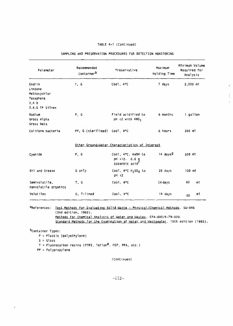
TABLE 4-1 (Cont inued)
SAMPLING AND PRESERVATION PROCEDURES FOR DETECTION MONITORING
Parameter
Minimum Volume Recomnended Maximum
P r e s e r v a t i v e Requ i red f o r c o n t a i n e r b Ho ld ing Time Analysis
Endr i n T, G Lindane
Methoxychlor Toxaphene
2,4 D 2.4,s TP S i l v e x
Radium Gross Alpha Gross Beta
Cool. 4OC 7 days 2,000 ml
F i e l d a c i d i f i e d t o 6 months 1 g a l l o n pH <2 Wl th HNOj
C o l i f o r m b a c t e r i a PP, G ( s t e r i l i z e d ) Cool , 4OC 6 hours 200 ml
Other Ground-Water C h a r a c t e r i s t i c s o f l n t e r e s
Cyanide
O i l and Grease G o n l y
Cool, 4OC, NaOH t o 14 daysg 500 ml pH >12. 0.6 g a s c o r b i c a c i d f
Cool, 4OC H2S04 t o 28 days 100 ml pH <2
S e m i v o l a t i l e . T, G Cool, 4OC
n o n v o l a t i l e o rgan ics
V o l a t i l e s G, 1 - l i n e d Cool , 4OC
1 4 days 60 ml
14 days 60 m1
aReferences: Test Methods f o r E v a l u a t i n a Sol i d Waste - Phvsica l /Chemical Methods, SW-846 (2nd e d i t i o n , 1982). Methods f o r Chemical Ana lvs is o f Water and Wastes, EPA-600/4-79-020. Standard Methods f o r t h e Examinat ion o f Water and Wastewater, 1 6 t h e d i t i o n (1985) .
b ~ o n t a i n e r Types:
P = P l a s t i c ( p o l y e t h y l e n e )
G = Glass T = F luorocarbon r e s i n s (PTFE, ~ e f l o n @ , FEP, PFA, e t c . )
PP = Polypropylene
(Cont inued)

TABLE 4-1 (Cont inued)
SAMPLING AND PRESERVATION PROCEDURES FOR DETECTION MONITORING
C ~ a s e d on t h e requi rements f o r d e t e c t i o n m o n i t o r i n g (5265 .931 , t h e owner /operator must c o l l e c t a s u f f i c i e n t volume o f grdund water t o a l l o w f o r t h e a n a l y s i s o f f o u r separa te rep1 i c a t e s .
d ~ h i p p i n g c o n t a i n e r s ( c o o l i n g chest w i t h i c e o r i c e pack) should be c e r t i f i e d as t o t h e 4OC temperature a t t ime o f sample placement i n t o these c o n t a i n e r s . P r e s e r v a t i o n o f samples r e q u i r e s t h a t t h e temperature o f c o l l e c t e d samples be a d j u s t e d t o t h e 4OC i m n e d i a t e l y a f t e r c o l l e c t i o n . Shipping c o o l e r s must be a t 4OC and ma in ta ined a t 4OC upon placement of sample and d u r i n g shipment. Maximum-minimum thermometers a r e t o be p laced i n t o t h e s h i p p i n g ches t t o r e c o r d temperature h i s t o r y . Chain-of -custody forms w i l l have Sh ipp ing /Rece iv ing and I n - t r a n s i t (max/min) temperature boxes f o r r e c o r d i n g data and v e r i f i c a t i o n .
e ~ o no t a l l o w any head space i n t h e c o n t a i n e r
ascorb ic a c i d o n l y i n t h e presence o f o x i d i z i n g agents.
g~aximum h o l d i n g t i m e i s 24 hours when s u l f i d e i s p resen t . O p t i o n a l l y , a l l samples may be t e s t e d w i t h l e a d a c e t a t e paper b e f o r e t h e pH adjustment i n o rder t o determine i f s u l f i d e i s present . I f s u l f i d e i s p resen t , i t can be removed by a d d i t i o n o f cadmium n i t r a t e powder u n t l l a n e g a t i v e spot t e s t i s obta ined. The sample i s f i l t e r e d and then NaOH i s added t o pH 12.

losses of organic material onto the walls of the container or aeration
may occur. Total organic halogens (TOX) and total organic carbon (TOC)
samples should be handled and analyzed as materials containing volatile
organics. No headspace should exist in the sample containers to minimize the possibility of volatilization of organics. Field logs and laboratory
analysis reports should note the headspace in the sample container(s) at
the time of receipt by the laboratory, as well as at the time the sample
was first transferred to the sample container at the wellhead.
Metallic ions that migrate through the unsaturated (vadose) and
saturated zones and arrive at a ground-water monitoring well may be
present in the well. Particles (e.g., silt, clay), which may be present
in the well even after well evacuation procedures, may absorb or adsorb
various ionic species to effectively lower the dissolved metal content in
the well water. Ground-water samples on which metals analysis will be
conducted should be split into two portions. One portion should be
filtered through a 0.45-micron membrane filter, transferred to a bottle,
preserved with nitric acid to a pH less than 2 (Table 4-l), and analyzed
for dissolved metals, The remaining portion should be transferred to a
bottle, preserved with nitric acid, and analyzed for total metals. Any
difference in concentration between the total and dissolved fractions may
be attributed to the original metallic ion content of the particles and
any sorption of ions to the particles.
The owner/operator must describe a chain-of-custody program in the
S&A plan. An adequate chain-of-custody program will allow for the
tracing of possession and handling of individual samples from the time of
field collection through laboratory analysis. An owner/operatorfs chain-
of-custody program should include:
Sample labels, which prevent misidentification of samples;
Sample seals to preserve the integrity of the sample from the time it is collected until it is opened in the laboratory;

Field logbook to record information about each sample collection during the ground-water monitoring program;
Chain-of-custody record to establish the documentation necessary to trace sample possession from the time of collection to analysis;
Sample analysis request sheets, which serve as official communication to the laboratory of the particular analysis(es) required for each sample and provide further evidence that the chain of custody is complete; and
Laboratory logbook and analysis notebooks, which are maintained at the laboratory and record all pertinent information about the sample.
4.4.1 Sample Labels
To prevent misidentification of samples, the owner/operator should
affix legible labels to each sample container. The labels should be
sufficiently durable to remain legible even when wet and should contain
the following types of information:
Sample identification number Name of collector Date and time, of collection Place of collection Parameter(s) requested (if space permits) Internal temperature of shipping container at time sample was placed Internal temperature of shipping container upon opening at laboratory Maximum and minimum temperature range that occurred during shipment
4.4.2 Sample Seal
In cases where samples may leave the owner/operatorts immediate
control, such as shipment to a laboratory by a common carrier (e.g., air
freight), a seal should be provided on the shipping container or
individual sample bottles to ensure that the samples have not been
disturbed during transportation.

4.4.3 Field Logbook
An owner/operator or the individual designated to perform ground-
water monitoring operations should keep an up-to-date field logbook that
documents the following:
Identification of well Well depth Static water level depth and measurement technique Presence of immiscible layers and detection method Well yield - high or low Purge volume and pumping rate Time well purged Collection method for immiscible layers and sample identification numbers Well evacuation procedure/equipment Sample withdrawal procedure/equipment Date and time of collection Well sampling sequence Types of sample containers used and sample identification numbers Preservative(s) used Parameters requested for analysis Field analysis data and method(s) Sample distribution and transporter Field observations on sampling event Name of collector Climatic conditions including air temperature Internal temperature of field and shipping (refrigerated) containers
4.4.4 Chain-of-Custody Record
To establish the documentation necessary to trace sample possession
from time of collection, a chain-of-custody record should be filled out
and should accompany every sample. The record should contain the
following types of information:
Sample number Signature of collector Date and time of collection Sample type (e.g., ground water, immiscible layer) Identification of well Number of containers Parameters requested for analysis Signature of person(s) involved in the chain of possession Inclusive dates of possession

Internal temperature of shipping (refrigerated) container (chest) when samples were sealed into the shipping container Maximum temperature recorded during shipment Minimum temperature recorded during shipment Internal temperature of shipping (refrigerated) container upon opening in the laboratory
4.4.5 Sample Analysis Request Sheet
This document should accompany the sarnple(s) on delivery to the
laboratory and clearly identify which sample containers have been
designated (e.g., use of preservatives) for each requested parameter.
The record should include the following types of information:
Name of person receiving the sample Laboratory sample number (if different from field number) Date of sample receipt Analyses to be performed Internal temperature of shipping (refrigerated) container upon opening in the laboratory
4.4.6 Laboratory Logbook
Once the sample has been received in the laboratory, the sample
custodian and/or laboratory personnel should clearly document the
processing steps that are applied to the sample. All sample preparation
techniques (e.g., extraction) and instrumental methods must be identified
in the logbook. Experimental conditions, such as the use of specific
reagents (e.g., solvents, acids), temperatures, reaction times, and
instrument settings, should be noted. The results of the analysis of all
quality control samples should be identified specific to each batch of
ground-water samples analyzed. The laboratory logbook should include the
time, date, and name of the person who performed each processing step.
4.5 Analytical Procedures
The S6A plan should describe in detail the analytical procedures
that will be used to determine the concentrations of constituents or
parameters of interest. These procedures should include suitable
analytical methods as well as proper quality assurance and quality
control protocols. The required precision, accuracy, detection limits,
and percent recovery (if applicable) specifications should be clearly
identified in the plan.
The S&A plan should identify one method that will be used for each
specific parameter or constituent. The plan should specify a method in
SW-846 or an EPA-approved method, and clearly indicate if there are going
to be any deviations fron the stated method and the reasons for these
deviations.
Records of ground-water analyses should include the methods used,
extraction date, and date of actual analysis. Data from samples that are
not analyzed within recommended holding times should be considered
suspect. Any deviation from an EPA-approved method (SW-846) should be
adequately tested to ensure that the quality of the results meets the
performance specifications (e.g., detection limit, sensitivity,
precision, accuracy) of the reference method.
4.6 Field and Laboratory Quality Assurance/Quality Control
One of the fundamental responsibilities of the owner/operator is
the establishment of continuing programs to ensure the reliability and
validity of field and analytical laboratory data gathered as part of the
overall ground-water monitoring program.
The owner/operatorls S&A plan must explicitly describe the QA/QC
program that will be used in the field and laboratory. Many owner/
operators use commercial laboratories to conduct analyses of ground-water
samples. In these cases, it is the owner/operator's responsibility to
ensure that the laboratory of choice is exercising a proper QA/QC
program. The QA/QC program described in the owner/operatorfs S&A plan
must be used by the laboratory analyzing samples for the owner/operator.
4.6.1 Field QA/QC Program
The owner/operator's S&A plan should provide for the routine
collection and analysis of two types of QC blanks: trip blanks and

equipment blanks. Each time a group of bottles is prepared for use in
the field, one bottle of each type (e.g., glass, fluorocarbon resin,
polyethylene) should be selected from the batch and filled with deionized
water. The bottles filled with the blank should be transported to the
sampling location and returned to the laboratory in a manner identical to
the handling procedure used for the samples. These trip blanks should be
subjected to the same analysis as the ground water. Any contaminants
found in the trip blanks could be attributed to (1) interaction between
the sample and the container, (2) contaminated rinse water, or (3) a
handling procedure that alters the sample analysis results. The
concentration levels of any contaminants found in the trip blank should
not be used to correct the ground-water data. The contaminant levels
should be noted, and if the levels are within an order of magnitude when
compared to the field sample results, the owner/operator should resample
the ground water.
Various types of field blanks should be used to verify that the
sample collection and handling process has not affected the quality of
the samples. The owner/operator should prepare each of the following
field blanks and analyze 'them for all of the required monitoring
parameters:
Trip Blank - Fill one of each type of sample bottle with Type I1 reagent grade water, transport to the site, handle like a sample, and return to the laboratory for analysis. One trip blank per sampling event is recommended.
Equipment Blank - To ensure that the nondedicated sampling device has been effectively cleaned (in the laboratory or field), fill the device with Type I1 reagent grade water or pump Type I1 reagent grade water through the device, transfer to sample bottle(s), and return to the laboratory for analysis. A minimum of one equipment blank for each day that ground-water monitoring wells are sampled is recommended.
The results of the analysis of the blanks should not be used to
correct the ground-water data. If contaminants are found in the blanks,

the source of the contamination should be identified and corrective
action, including resampling, should be initiated.
All field equipment that the owner/operator will use should be
calibrated prior to field use and recalibrated in the field before
measuring each sample. The owner/operatorts S&A plan should describe a
program for ensuring proper calibration of field equipment. Other QA/QC
practices such as sampling equipment decontamination proc,edures and
chain-of-custody procedures should also be described in the
owner/operator1s S&A plan.
4.6.2 Laboratory QA/QC Program
The owner/operator's S&A plan should provide for the use of
standards, laboratory blanks, duplicates, and spiked samples for
calibration and identification of potential matrix interferences. The
owner/operator should use adequate statistical procedures (e.g., QC
charts) to monitor and document performance and implement an effective
program to resolve testing problems (e.g., instrument maintenance,
operator training). Data from QC samples (e.g., blanks, spiked samples)
should be used as a measure of performance or as an indicator of
potential sources of cross-contamination, but should not be used to alter
or correct analytical data. These data should be submitted to the Agency
with the ground-water monitoring sample results.
4.7 Evaluation of the Quality of Ground-Water Data
A ground-water sampling and analysis program produces a variety of
hydrogeological, geophysical, and ground-water chemical constituent
(GWCC) data. This section pertains primarily to the evaluation of GWCC
data because these data are specifically required by the regulations, are
evaluated in the statistical tests, provide the fundamental evidence used
to determine whether the facility is contaminating the ground water, and
are used to determine the extent of plume migration during assessment
monitoring. Also, details regarding how to obtain and identify quality

hydrogeological and geophysical data have been discussed earlier. The
GWCC data may be initially presented by the laboratory (by electronic
transmittal or) on reporting sheets; these data then must be compiled and
analyzed by the owner/operator prior to submission to the state or EPA in
order to evaluate the degree of ground-water contamination.
It is essential for owner/operators to make sure that, during
chemical analysis, laboratory reporting, computer automation, and report
preparation, data are generated and processed to avoid mistakes, and that
data are complete and fully documented. Data must be reported correctly
to have accurate analyses and valid results. If data errors do occur,
statistical analyses cannot discover, correct, or ameliorate these errors.
The following discussion considers aspects of data quality that may
indicate to the technical reviewer that the data acquisition, processing,
and evaluation were executed poorly or incorrectly.
The specific areas that are addressed include:
Reporting of low and zero concentration values; Missing data values; Outliers; and Units of measure.
4.7.1 Reportinq of Low and Zero Concentration Values
A critical concern is the interpretation, reporting, and analysis of
GWCCs that are measured at less than (LT) a limit of detection. LT limit
of detection values presently result from a variety of laboratory
conventions and protocols. Technical reviewers, during the review of
data submissions, may confront a variety of codes indicating that GWCC
concentrations are below a value which the laboratory designates as the
detection limit.
Values that are LT a limit of detection can result when:
GWCCs are present at low concentrations; An insensitive analytical technique has been used; and The chemical matrix of the ground water interferes with the analytical technique.
The following guidelines should help the technical reviewer identify
problems associated with the reporting of LT detection limit values,
analyze the data sets that contain LT detection limit values, and
prescribe remedies for future owner/operator submissions.
GWCC should be given close attention if the LT detection limit
values appear to increase over time. Increasing detection limits may be
used to conceal an increasing concentration trend. Similarly, if back-
ground data are reported without a LT designation at low concentrations
and comparison downgradient data are presented at higher concentrations
with a LT designation, then it is possible that LT detection limit values
are being used to conceal larger downgradient concentrations. It is
unacceptable to report onlg qualitative information for values that were
measured below a limit of detection. The technical reviewer must ensure
that numerical values accompany the LT designation, so that data are
available for analysis. LT detection limit values that are high or that
vary should be reduced in future work by laboratory procedures that
remove or control interfering constituents.
The owner/operator must explain and follow a specific laboratory
protocol for determining and reporting low concentration values.
Technical reviewers should not allow the use of highly variable reporting
formats. An appropriate protocol for determining and reporting GWCC data
at low concentrations is described in Appendix B of 40 CFR 5136, titled
"Definition and Procedure for the Determination of the Method Detection
Limit - Revision 1.11." Other methods are offered by the American
Chemical Society and the International Union of Pure and Applied
Chemistry . LT values should not be deleted from the analysis. Instead, when
data sets consist of a mixture of values that are LT a limit of detection
and actual concentration measurements, LT values may be analyzed at half
their reported value. This technique is simple to use and has been
presented for use in the following references:

Gilbert, R.O. and Kinnison, R.R. 1981. Statistical Pethods for Estimating the Mean and Variance from Radionuclide Data Sets Containing Negative, Unreported, or Less than Values. Health Pl~ysics 40 : 377-390.
Nehls, G.J. and Akland G.G. 1973. Procedures for Handling Aerometric Data. Journal of the Air Pollution Control Association 23:180-184.
LT values may also be analyzed using Cohen's Method. This method is also
simple to use and has been described by:
Cohen C. 1961. Tables for Maximum Likelihood Estimates from Singly Truncated and Singly Censored Samples. Technometrics 3:535-541.
Finally, a variety of other techniques, which are slightly more
complicated, are described in the following references:
Gilliom, R.J. and Helsel, D.R. 1986. Estimation of Distributional Parameters for Censored Trace Level Water Quality Data. 1. Esti- mation Techniques. Water Resources Research 22:135-146.
Helsel, D.R. and Gilliom, R.J. 1986. Estimation of Distributional Parameters for Censored Trace Level Water Quality Data. 2. Verifi- cation and Applications. Water Resources Research 22:147-155.
In some cases, the technical reviewer will be confronted with a
situation where the values for a chemical constituent in the back-
ground well system are LT a limit of detection. In this case, no data
are available to estimate the background variance, and the background
mean will be biased higher than its actual value, which is some value LT
the limit of detection. In this case, the technical reviewer should
ensure that laboratory protocols and data which are used to establish the
detection limit values are provided. In addition, it is recommended
that, especially in this case, the laboratory should ensure that any
values, which are reported above a limit of detection, are quantifiable.
The American Chemical Society's LOQ or the upper confidence limit of
EPA's MDL may be used to establish a threshold criteria.
4.7.2 .Missing Data Values
Owner/operators incur a substantial risk of missing an extreme
environmental event and measurement of particularly large or small values

if they fail to collect all of the data required for a monitoring program.
This may result in an incomplete measure of environmental variability and
an increased likelihood of falsely detecting contamination. Also, if
assessment monitoring data are missing, there is a danger that the full
extent of contamination may not be characterized. Owner/operators must
take extreme care to ensure that concentration measurements result from
all samples taken. Nevertheless, the technical reviewer is likely to
confront situations where complete detection monitoring data have not
been collected. The technical reviewer should have the owner/operator
perform the t-test despite incomplete data collection, provided that the
following criteria have been met:
If there are data from one upgradient well and one downgradient well, statistical comparisons should still be made. If data exist for three quarters at a well, statistical comparisons should be made after applying the rule described in the next bullet.
If only one quarter of data is missing, values should be assigned for the missing quarter by averaging the values obtained during the other three quarters.
If there are missing replicate measurements from a sampling event, then average the replicate(s) that are available for that sampling event.
These guidelines have been described previously in the November 1983 EPA
memorandum on statistical analyses of indicator parameter data. The
intent of this methodology is to encourage use of the t-test, despite
prior noncompliance with the data collection requirements in the
regulations, so that a determination can be made as to whether assessment
monitoring should begin. Regardless of whether there are sufficient data
for performing the t-test, the technical reviewer should consider taking
enforcement action to compel additional sampling on an accelerated
schedule. The technical reviewer must minimize delays in the evaluation
of a facility's ground water because of prior incomplete data collection.

4.7.3 Outliers
A GWCC value that is much different from most other values in a data
set for the same GWCC can be referred to as an "outlier." The reasons
for outliers can be:
A catastrophic unnatural occurrence such as a spill;
Inconsistent sampling or analytical chemistry methodology;
Errors in the transcription of data values or decimal points; and
True but extreme GWCC concentration measurements.
The technical reviewer should attempt to have owner/operators
correct outlying values if the cause of the problem can be documented and
corrected by the owner/operator without delay. The data should be
corrected if outliers are caused by incorrect transcription and the
correct values can be obtained and documented from valid owner/operator
records. Also, if a catastrophic event or a problem in methodology
occurred that can be documented, then data values should be from
calculations with clear reference to this deletion at all relevant
stages. Documentation and validation of the cause of outliers must
accompany any attempt to correct or delete data values, because true but
extreme values must not be altered. The technical reviewer should not
accept the mere presence of an extreme value in data or the effect of an
extreme value on the statistical analysis as a valid reason for the
continuation of detection monitoring.
Ground-water contaminant concentrations when influenced by a
hazardous waste management facility do not necessarily vary gradually.
Instead, it is not uncommon for contamination (e.g., halogenated organic)
to be reflected in a series of data collected over time with the following
trend. Measurements remain below a limit of detection and then, in a
single or several sampling event(s), concentrations rise to measurable
levels and soon return to concentrations which are LT a limit of detection

in subsequent sampling periods. In general, technical reviewers should
not accept the contention that contaminant concentrations measured in
wells immediately downgradient or in the vicinity of hazardous waste
management areas increase only gradually. Rapidly increasing and
decreasing concentrations can occur in ground waters subjected to con-
tamination; the high concentrations in these cases would be true extreme
values but not outliers.
4.7.4 Units of Measure
Associated with each GWCC value is a unit of measure that must, be
reported accurately. Mistakes in the reporting of the units of measure
can result in gross errors in the apparent concentrations of GWCCs. For
example, a lead value of 30.2 might have a unit of measure of parts per
billion (ppb). Alternatively, the same lead value of 30.2 might have
been incorrectly reported with a unit of measure in parts per million
(ppm). The reported value would transform to a concentration with the
units of measure in ppb as 30,200 ppb of lead or three orders of
magnitude larger than it was measured.
The following guidelines should help the technical reviewers
ensure that units of measure associated with data values are reported
consistently and unambiguously:
The units of measure should accompany each chemical parameter name. Laboratory data sheets that include a statement "values are reported in ppm unless otherwise noted" should generally be discouraged but at least reviewed in detail by the technical reviewer. It is common to find errors in reporting the units of measure on this type of data reporting sheet especially when these reporting sheets have been prepared manually.
The units of measure for a given chemical parameter must be consistent throughout the report.
Finally, reporting forms for detection monitoring, as specified in the EPA November 1983 memorandum, and the data presentation methods described in Chapter Five should help to reduce problems associated with the reporting of units of measure.


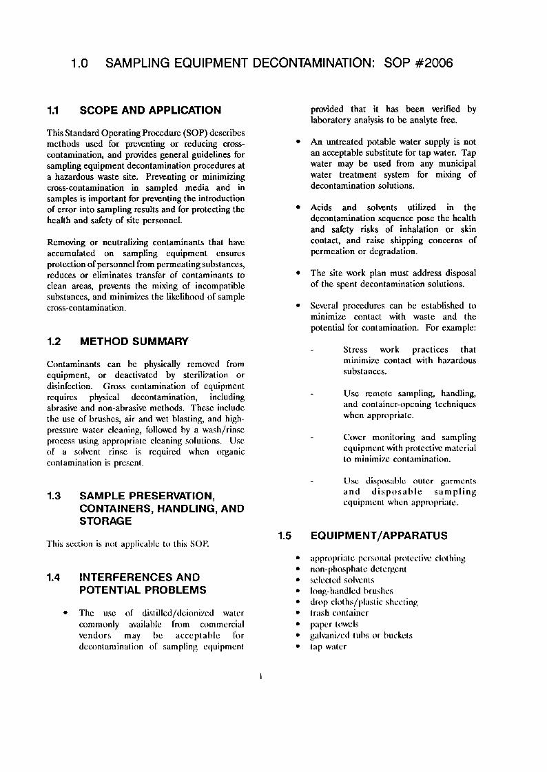


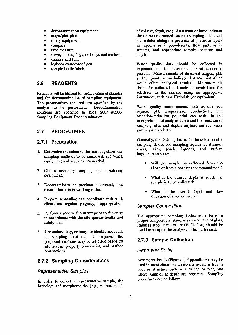


UST Branch: Closure Plan Requirements
R311-204, Utah Administrative Code (U.A.C.), requires Underground Storage Tank (UST) owners/operators to submit a Closure Plan outlining the details of the UST closure to the Executive Secretary (UST), Utah Solid and Hazardous Waste Control Board.
1. The Owner(s)/Operator(s) (O/O) must submit to the Division of Environmental Response and Remediation (DERR) a completed "CLOSURE PLAN" which must be approved before commencing closure of the UST. A contractor may complete the closure plan, however the O/O is responsible for compliance with the UST rules and regulations.
2. For closure in-place or change in service, the Closure Plan must now be submitted and approved prior to completing the site assessment.
3. The approved Closure Plan is valid for one year from the approval date. If closure does not take place within one year the O/O must submit a new Closure Plan for approval.
4. The O/O must notify the Local Health and Fire Departments and the DERR/UST at least 72 hours prior to starting closure activities.
5. The certified UST remover and sampler performing the closure must have a current Utah certification and follow the approved Closure Plan. Changes to an approved plan must be submitted in writing to the Executive Secretary and approved before closure.
6. The O/O must have a copy of the approved Closure Plan on-site during closure activities. 7. The O/O must ensure the completion of a site assessment in accordance with 40CFR 280.72 and R311-205, U.A.C.
Indicate the proposed sample locations on the Facility Site Plat of the Closure Plan and complete the Sample Information Table. If contamination is encountered or suspected at locations other than the approved sample locations, additional samples must be collected at the location(s) where contamination is most likely to be present. If groundwater is encountered a soil sample must be collected, in the unsaturated zone, in addition to each groundwater sample.
8. The O/O must report suspected or confirmed contamination (any amount) to the Executive Secretary by reporting to the DERR/Leaking Underground Storage Tanks (LUST) section at (801)536-4100 within 24 hours of discovery.
9. The O/O must submit to the DERR a Closure Notice within 90 days after the tank closure. The Closure Notice should include:
a. A properly completed Closure Notice form signed by the owner and certified groundwater and soil sampler.
b. An updated Site Plat and a Sample Information Table with actual depths and locations of all samples, including depth of ground water.
c. Analytical results of samples
d. A Chain of Custody Form
10. The O/O must pay Registration and PST Fund fees for the assessment period in which the tank is closed and all other unpaid fees.
11. If contamination is suspected or confirmed during UST closure activities, or is based on analytical results, the O/O may receive a reporting and remediation schedule from the DERR/LUST section, outlining their obligation to characterize and possibly remediate the release. Any person providing remedial assistance for a fee, including over-excavation (of more than 50 yd3) and aeration, must be a Certified UST Consultant (a list is available from the DERR). Expenses to be applied toward the Petroleum Storage Tank (PST) Fund deductible must meet the same test of reasonable, customary and legitimate as expenses submitted for reimbursement. For expenses above the $10,000 deductible to be eligible for reimbursement from the PST Fund, all work plans and budgets must be approved the State Project Manager before any work begins
Refer questions concerning the Closure Plan approval process to the DERR/UST section at 801-536-4100.
Send the completed Closure Plan to:
State of Utah Department of Environmental Quality Division of Environmental Response and Remediation UST Section P.O. Box 144840 195 North 1950 West Salt Lake City, Utah 84114-4840
Page 1 of 1Utah: DEQ: DERR: UST Branch: Closure Plan
7/18/2011http://www.undergroundtanks.utah.gov/closure_req.htm

1
UNDERGROUND STORAGE TANK CLOSURE PLAN (rev. 1/05) FACILITY ID# …
LHD USE ONLY
Date Received
Reviewer
Date LHD Approved
Date mailed to State
Closure Plan prepared at the request of the owner/operator (identified below) by of (company name) Phone # Address City State Zip A Contractor may prepare this Closure Plan as the owner/operator's agent. In preparing the Closure Plan, the Contractor must act with the owner/operator's knowledge and approval. The owner/operator must sign the Closure Plan. This Closure Plan is submitted in compliance with the requirements contained in 40 CFR 280 Subpart G and R311-204 (U.A.C.)
Tank #
Type (Steel,FRP,etc.)
Date Installed
Capacity
Substance stored*
Date last operated Removed/In Place/ Change in Service (CIS)?
*Indicate the specific substance stored in each tank to be closed (regular, unleaded, diesel, waste oil, etc.)
For waste oil tanks: Have degreasing or other types of solvents been stored or mixed with the waste oil? Yes (identify if known) . No Not Known Analysis for lead or other contaminants may be required prior to disposal of contaminated soil or other material. (Check with your disposal facility.)
STATE USE ONLY Date Received Date Mailed to LHD Date Received From LHD Reviewer/Date Approved Mgr. Review/Date
FACILITY INFORMATION Tank Owner Phone #
sole proprietorship partnership corporation
Address City State Zip
Facility Name Address City State Zip Contact person Phone #
Total number of regulated underground tanks at this site
Total number of regulated underground tanks at this site to be closed

2
Before the closure plan is submitted for approval, the local health and fire departments where the facility is located must be contacted. If the facility is in Beaver, Carbon, Davis, Emery, Garfield, Grand, Iron, Kane, Salt Lake, San Juan, Wasatch, or Washington county contact DERR (UST) at (801)536-4100 instead of the local health district. You still must contact the local fire department in these counties.
CONTACT LOCAL HEALTH DISTRICT: Name of Dist. Date
Contact Title Phone#
CONTACT LOCAL FIRE DEPT. Name of Dept. Date
Contact Title Phone#
DISPOSAL INFORMATION
Tank(s) will be disposed at: Facility
Address City State Zip
Contact person Phone# Product lines will either be: removed or cleaned, secured in place, and capped.
Vent lines will either be: removed or cleaned and secured open.
Piping will be disposed at: Facility
Address City State Zip Contact person Phone# Tank(s) will be emptied by: company Phone# Tank(s) will be cleaned by: company Phone# Contaminated water in the tank/rinsate will be disposed at: Facility
Contact person Phone# Tank(s) will be: purged or rendered inert by the following method:
Residual sludges will be disposed at the following facility:
Address City State Zip Contact person Phone#
FOR CLOSURE IN PLACE ONLY
Approval for in-place closure has been granted by the Local Fire Department.
Fire Dept. Phone# Contact person Date
Approval for in-place closure has been granted by the Local Health Department.
Health Dept. Phone# Contact person Date Substance to be used to fill tanks:
TANK REMOVER Name Cert. # TR Exp. Date
Company Phone #
Address City State Zip
SOIL/GROUNDWATER SAMPLER Name Cert. # GS Exp. Date
Company Phone # Address City State Zip

3
SITE ASSESSMENT A site assessment must be performed for all UST closures and change-in-service. Site assessments must be performed as outlined in 40 CFR 280.72 and R311-205 (U.A.C.). If contamination is suspected, additional samples must be collected at the location where contamination is most likely to be present. If groundwater is encountered, a soil sample must be collected, in the unsaturated zone, in addition to each groundwater sample. Soil and groundwater samples must be analyzed for the compounds shown in the following table, using appropriate lab methods.
ANALYTICAL METHODS1
Substance or Product Type
Contaminant Compounds to be Analyzed for Each
Substance or Product Type Soil, Groundwater or Surface Water
Total Petroleum Hydrocarbons (purgeable TPH as gasoline range organics C6 - C10)
EPA 8015B or EPA 8260B
Gasoline
Benzene, Toluene, Ethyl benzene, Xylenes, Naphthalene, (BTEXN) and MTBE
EPA 8021B or EPA 8260B
Total Petroleum Hydrocarbons (extractable TPH as diesel range organics C10 – C28)
EPA 8015B
Diesel Benzene, Toluene, Ethyl benzene, Xylenes, and Naphthalene (BTEXN)
EPA 8021B or EPA 8260B
Oil and Grease (O&G) or Total Recoverable Petroleum Hydrocarbons (TRPH)
EPA 1664A or EPA 1664A (SGT*)
Used Oil Benzene, Toluene, Ethyl benzene, Xylenes, Naphthalene (BTEXN) & MTBE; and Halogenated Volatile Organic Compounds (VOX)
EPA 8021B or EPA 8260B
New Oil
Oil and Grease (O&G) or Total Recoverable Petroleum Hydrocarbons (TRPH)
EPA 1664A or EPA 1664A (SGT*)
Other
Type of analyses will be based upon the substance or product stored, and as approved by the Executive Secretary (UST)
Method will be based upon the substance or product type
Total Petroleum Hydrocarbons (purgeable TPH as gasoline range organics C6 - C10)
EPA 8015B or EPA 8260B
Total Petroleum Hydrocarbons (extractable TPH as diesel range organics C10 – C28)
EPA 8015B
Oil and Grease (O&G) or Total Recoverable Petroleum Hydrocarbons (TRPH)
EPA 1664A or EPA 1664A (SGT*)
Unknown
Benzene, Toluene, Ethyl benzene, Xylenes, and Naphthalene (BTEXN) and MTBE; and Halogenated Volatile Organic Compounds (VOX)
EPA 8021B or EPA 8260B
1 The following modifications to these certified methods are considered acceptable by the Executive Secretary (UST): • Dual column confirmation may not be required for TPH and BTEXN/MTBE analysis. • A micro-extraction or scale-down technique may be used for aqueous samples, but only for the determination of extractable TPH as diesel range
organics (C10 – C28). • Hexane may be used as an extraction solvent. • *Silica Gel Treatment (SGT) may be used in the determination of Total Recoverable Petroleum Hydrocarbons.
NOTE: The sample preparation method and any modification(s) to a certified method must be reported by the laboratory.

4
CONTAMINATED MATERIALS MUST BE DISPOSED AT AN ACCEPTABLE FACILITY: All materials generated from UST closures must be managed and disposed in a manner that does not place those materials in direct contact with the environment. On-site stockpiling of contaminated soils may be required prior to any soil management activities. Any person providing remedial assistance for a fee, including aeration and over-excavation (of more than 50 yd3), must be a Certified UST Consultant.
Contaminated soils generated as part of tank removal are to be disposed at the following facility: Address City State Zip Contact person Phone
Complete the Facility Site Plat and Sample Information Table on pages 4 and 5 to provide site assessment information. CONTAMINATION INFORMATION If contamination at the facility is suspected or confirmed, the information must be reported to the Executive Secretary (UST) at (801) 536-4100 within 24 hours. The Division of Water Quality must be notified at (801) 538-6146 if Free Product is encountered or if surface water has been impacted. If contamination is confirmed, any person assisting in the remediation process for a fee must be a Certified UST Consultant.
SAMPLE INFORMATION TABLE Complete table for all samples to be taken for closure.
1 Soil (SS), Groundwater (GW), or Unified Soil Classification (USC). 2 Approx. depth in feet below grade. The required minimum site assessment samples must be taken at 0-2 feet below the backfill/native soil interface. 3 Contaminant compounds to be analyzed for each sample (from table on p. 3). 4 Appropriate analysis methods for contaminant compound(s) in each sample (from table on p. 3).
Sample #
Substance stored in
tank
Sample type1 Depth2 Compounds3 Analysis method(s)4

5
Facility Site Plat (Closure Plan) The site plat must be drawn to an appropriate identified scale. It must show planned sampling locations, substances stored in tanks, and other relevant information. Tank and sample identification numbers must be consistent with the information given on p. 1 and 4 of the Closure Plan.
Facility ID: Drawn By: Date:
X = Sample locations (SS-#, WS-#, USC-#) Site Plat Must Indicate Approximate Locations Of: θ = Monitoring Wells (MW-#,) Υ Current & former tanks, piping & dispensers F = Soil boring (SB-#), or Geoprobe Boring (GP-#) Υ Location of all samples to be taken M = Water Wells (domestic, livestock, etc.) Υ Buildings, fences, & property boundaries Slope of Surface Topography: (N,NW,W,SW,S,SE,E,NE) Υ Utility conduits (sewers, gas, water, storm drains, Land Use At Site: Residential Commercial Industrial electrical, etc.) Surrounding Land: Residential Commercial Industrial
North
Scale: 1”= Feet

6
Approximate depth to groundwater in the vicinity of the tanks: feet.
Regional groundwater flow direction:
State Certified Laboratory to be used:
Address City State Zip
Contact Person Phone
I certify under penalty of law that I am the owner/operator of the tank(s) referenced above and that I am familiar with the information on this form and that it is true, accurate and complete, and further, that the procedures described herein will be followed during tank closure.
Signature of tank owner Full Name of tank owner Date
Please explain any unusual or extenuating circumstances expected regarding the site assessment or closure:

1
UNDERGROUND STORAGE TANK PERMANENT CLOSURE NOTICE (rev. 3/4/03) FACILITY ID# . …
State Use Only Date Processed by Date Mailed to LHD LUST ID# Date to LUST Review
Closure Notice prepared at the request of the owner/operator (identified below) by of (company name) Phone # Address City State Zip
TANKS CLOSED
Tank #
Type (Steel,FRP,etc.)
Date Installed
Capacity (Gallons)
Substance stored*
Date last operated
Date Closed Removed/In Place/ Change in Service (CIS)?
*Indicate the specific substance stored in each tank to be closed (regular, unleaded, diesel, waste oil, etc.)
CLOSURE INFORMATION Fuel was emptied Sludge was removed Tank was cleaned Tank was: Purged Inerted Method Used: Location of Closure Records: For In-Place Closure: tanks filled with: For Change-In-Service: Substance to be stored:
FACILITY INFORMATION
Tank Owner Phone #
sole proprietorship partnership corporation
Address City State Zip
Facility Name Address City State Zip Contact person Phone #
Total number of regulated underground tanks at this site before closure
Total number of regulated underground tanks at this site after closure
TANK REMOVER Name Cert. # TR Exp. Date Company Phone # Address City State Zip SOIL/GROUNDWATER SAMPLER Name Cert. # GS Exp. Date Company Phone # Address City State Zip

2
DISPOSAL SITES USED Location Name Contact Name Phone # Date Amount
Tank(s) Tank #
Product From Tank(s) Contaminated Water From Tank Cleaning
Sludge Contaminated Water From Excavation
Contaminated Soil SITE ASSESSMENT
Complete the Facility Site Plat (Closure Notice) and Sample Information Table (Closure Notice) on pages 3 and 4 to show the locations, depths, and other information on all soil/groundwater samples taken for closure. The samples must be consistently identified by sample ID # on the site plat, table, and lab analysis report.
Completed Facility Site Plat (Closure Notice) is attached. The following must be included (enter the distance, and direction (N,S,E,W) from the area of contamination or, where applicable, use OH for overhead, NP for not present): Water Line Sewer Line Natural Gas Storm Drain Telephone Electrical Property Line Buildings
Completed Sample Information Table (Closure Notice) is attached. Certified lab analytical environmental sample results are attached. Unified Soil Classification (USC) sample results are attached. Chain of Custody form is attached.
Samples were properly: Collected Labeled Packaged Transported Samples were in sight of the person in custody at all times or in a secured locked place.
I certify under penalty of law that the closure site assessment at this facility was conducted in accordance with R311-202 (parts 280.52 and 280.72) and R311-205 U.A.C., and that any additional samples required by R311-202 parts 280.52 and 280.72 and R311-205-2(a)(1) were properly collected.
Signature of Certified Groundwater/Soil Sampler
Full name of Certified Sampler Date If contamination at the facility is confirmed, any person providing remedial assistance for a fee must be a Certified UST Consultant. The Certified UST Consultant providing assistance is: CERTIFIED UST CONSULTANT
Name Cert. #CC Exp. Date
Company Address
City State Zip Phone #
Please explain any unusual or extenuating circumstances expected regarding the site assessment or closure:

3
Facility Site Plat (Closure Notice) The site plat must be drawn to an appropriate identified scale. It must show planned sampling locations, substances stored in tanks, and other relevant information. Tank and sample identification numbers must be consistent with the information given on p. 1 and 4 of the Closure Notice.
Facility ID: Drawn By: Date: X = Sample locations (SS-#, WS-#, USC-#) Site Plat Must Indicate Actual Locations Of: ρ = Monitoring Wells (MW-#,) √ Current & former tanks, piping & dispensers
= Soil boring (SB-#), or Geoprobe Boring (GP-#) √ Location of all samples to be taken ● = Water Wells (domestic, livestock, etc.) √ Buildings, fences, & property boundaries Slope of Surface Topography: (N,NW,W,SW,S,SE,E,NE) √ Utility conduits (sewers, gas, water, storm drains, electrical, etc.) Land Use At Site: Residential Commercial Industrial √ Depth to groundwater (if encountered) Surrounding Land: Residential Commercial Industrial √ Excavations, GW monitoring wells & soil stockpiles
North
Scale: 1”= Feet

4
SAMPLE INFORMATION TABLE (Closure Notice)
Complete table for all samples that were taken for closure. Sample ID numbers on the table must be consistent with the sample ID numbers given on the site plat and in the lab analysis report.
1 Soil (SS), Groundwater (GW), or Unified Soil Classification (USC). 2 Final depth (in feet) below grade at which samples were taken. 3 Contaminant compound(s) analyzed for each sample (TPH, BTEXN, O&G, etc). 4 Appropriate analysis methods for contaminant compound(s) in each sample
State Certified Laboratory used Address City State Zip Contact Person Phone #
I certify under penalty of law that I am the Owner of the tank(s) described above and that I am familiar with the information on this form and that it is true, accurate and complete and further, that the procedures described herein were followed during tank closure.
Signature of UST owner Full Name of owner Date
Return completed Closure Notice form, Facility Site Plat and Sample Information Table, Soil/Groundwater sample lab analysis results, USC sample results, and Chain of Custody form within 90 days of UST Closure to: State of Utah Dept. of Environmental Quality Division of Environmental Response and Remediation / UST Section P.O. Box 144840 195 North 1950 West Salt Lake City, Utah 84114-4840
Sample #
Substance stored in tank
Sample type1 Depth2 Compounds3 Analysis method(s)4

Other DEQ Division Requirements
INTRODUCTION
Other Divisions of the DEQ have requirements that are applicable to UST sites. These requirements are briefly discussed below.
GROUNDWATER MONITORING WELL PERMITTING REQUIREMENTS
The Utah Division of Water Rights (DWR) requires that all groundwater monitoring wells in the state of Utah constructed to a depth of 30-feet or greater below natural ground surface shall be properly permitted, and properly installed by a well driller currently licensed in the State of Utah. The DWR must be contacted for well installation procedures and any other permit requirements contained in the Division's Administrative Rules for Water Well Drillers. Any documentation of the notification and any permits or approvals obtained must be submitted to DERR. Applicable sections in Administrative Rules for Water Well Drillers include: R655-4-4 General Procedural Requirements; and R655-4-7 Minimum Construction Requirements.
GROUNDWATER MONITORING WELL ABANDONMENT PROCEDURES
The Utah Division of Water Rights must be notified at (801) 538-7240 for well installation, abandonment procedures, and any other permit requirements contained in Administrative Rules for Water Well Drillers. Documentation of the notification and any permits or approvals obtained must be submitted to the DERR. Well abandonment requirements are contained in State Regulation R655-4- 12, Administrative Rules for Water Well Drillers.
BLUE STAKES REQUIREMENTS
Section 54-8a- 1 thru 11 of the Utah Code Annotated 1953, as Amended in 1993, Damage to Underground facilities requires that Blue Stakes (1-800-662-41 11) must be notified by telephone at least 2 working days before excavating or drilling at an UST site, and that the work must begin within 7 days of the request. Excavation or any digging at the site without first calling Blue Stakes is "prima facie" evidence of negligence.
AIR EMISSIONS
The Utah Division of Air Quality (DAQ) must be notified at (801) 536-4000 prior to any release of petroleum vapors from free product removal, soil or groundwater treatment, so a determination can be made whether or not an Air Permit is required. Documentation of the notification and any permits or approvals obtained must be submitted to the DERR. DAQ requirements are contained in State Regulation R307-6 "De minimis Emissions from Air Strippers and Soil Venting Projects."
HAZARDOUS WASTE
Improper disposition and aeration of petroleum-contaminated soils and other hazardous wastes

from leaking underground storage tank sites could potentially cause public health and environmental problems. The ownerloperator (010) is responsible for notifying and obtaining approval from the DERR, the DAQ, local health departments, and local fire agencies prior to any soil management activity at an underground storage tank site. As outlined in State Regulation R3 1 1-204-2, the Executive Secretary of the Utah Solid and Hazardous Waste Control Board approves closure plans which includes information concerning contaminated soils management.
POTW REQUIREMENTS
Publically Operated Treatment Works (POTW) requirements concerning pretreatment regulations and discharge concentrations of groundwater impacted by petroleum free-phase or dissolved product are site and Sewer District specific. If an ownerloperator (010) is planning to dispose of water from a water treatment system, a permit from the Utah Division of Water Quality (DWQ) at (801) 538-6146 must be obtained. Additionally, the specific local sanitary sewer district must be contacted before any treated or untreated waters are discharged to the sanitary sewer. Documentation of the notification and any permits or approvals obtained must be submitted to the DERR.
LOCAL HEALTH DEPARTMENT AUTHORITYRESPONSIBILITY
Local health and fire departments must be notified of installation or closure of underground storage tanks, treatment of petroleum contaminated soils on-site or the storage of free product on-site, if any. Some local health and fire departments require prior approval of the installation or closure of underground storage tanks and must be notified at least 72 hours prior to any such activity.
STORM DRAIN AND RECEIVING STREAM DISCHARGE REGULATIONS
If an ownerloperator of an UST site is aware that groundwater has been impacted by petroleum free-phase or dissolved product, or that surface waters have been contaminated, the DWQ must immediately be notified (801) 538-6146. Any required permits such as the Utah Pollution Discharge Elimination System (UPDES) permit must be obtained prior to initiating corrective action of abatement measures. The UPDES permit is required if treated water will be disposed to surface waters including streams, ditches, storm drains, or lakes.
REINJECTION OF CONTAMINATED MEDIA REGULATIONS
An Underground Injection Control (UIC) Permit is required when placing or re-injecting treated water back into the ground. The permit must be secured from the DWQ at (801) 538-6146 prior to implementing any corrective action or abatement measures. Documentation of the notification and any permits or approvals obtained must be submitted to the DERR. UIC rules and regulations are found in Utah Administrative Code R3 17-7.

Utah Administrative Code R655-4 Water Well Drillers
R655-4- 1 1. Drilling of Monitor Wells.
1 1.0 General.
All monitor wells in the state constructed to a depth of 30 feet or greater below natural ground surface shall be installed by a currently licensed well driller.
1 1.1 Approval.
Approval to drill monitor wells is issued by the state engineer following review of written requests from the owner or applicant, federal or state agency or engineering representative. The requests for approval shall be made on forms provided by the state engineer and shall include the following information:
1 ) General location or common description of the monitoring project.
2) Specific course and distance locations from established government surveyed outside section comers or quarter comers or location by 1/4, 114 section.
3) Total anticipated number of wells to be installed.
4) Diameters, approximate depths and materials used in the wells.
5) Projected start and completion dates.
6) Name and license number of the driller contracted to install the wells.
1 1.2 Start CardIOfficial Well Drillers Report.
Upon written approval by the state engineer the project will be assigned an approved authorization number which will be referenced by the licensed driller on all intention to drill (start) cards and official well drillers reports as required in Section R655-4.1.1 and Section R655-4.3.
1 1.3 Installation and Construction.
11.3.1 All material used in the installation of monitor wells shall be sterile and contaminant free when placed in the ground. During construction contaminated water should not be allowed to enter contaminant-free geologic formations or water bearing zones. 1 1.3.2 Some minor cross-contamination may occur during the drilling process, but the integrity of the borehole and individual formations must then be safeguarded.
11.3.3 The well casing should be perforated or screened and filter packed with sand or gravel where necessary to provide adequate sample collection at depths where appropriate aquifer flow

zones exist. The annular space brtu.een the borehole and casing should be adequately sealed ~lsing bentonite-slurry. pellets. grunules or chips. cement grout or neat cement.
1 1.3.4 The gravel or filter pack should generally extend two feet to ten feet above screened or perforated areas to pre\lent the migration of the sealing material from entering the zones being sampled. Drill cutting should not be placed into the open borehole annulus. Figure 6. dated December 15, 1994 refers to typical groundwater monitor well construction standards and is incorporated by reference to these rules.
1 1.4 Abandonment.
Abandonment of monitor wells shall be completed in compliance with the provisions of Sections R655-4- 12.1 through R655-4- 12.12. The provisions of subsection R655-4- 12.4(4) are not required for the permanent abandonment of monitor wells or wells completed less than 30 feet below natural ground surface.
1 1.5 Summary
Most monitor well projects are the result of compliance with the Environmental Protection Agency (EPA). Federal Regulations such as the Resource Conservation and Recovery Act (RCRA), Comprehensive Environmental Response. Compensation and Liability Act (CERCLA or "Superfund"), or specific State Solid and Hazardous Waste requirements. The contracts governing their installation are tightly written containing specific requirements as to site location, materials used, sampling procedures and overall objectives. Therefore specific construction requirements for monitor well installation shall be governed by applicable contracts and reguiations providing they meet or exceed state requirements and specifications. Guidelines and recommended practices dealing with the installation of monitor wells may be obtained from the srate engineer upon request. Additional recommended information may be obtained from the Environmental Protection Agency I EPA), Resource Conservation and Recovery Act I RCRA). Groundwater monitoring Enforcement and Compliance Document available from EPA's regional office in Denver. Colorado and from the Handbook of Suggested Practices for the Design and Installation of Groundwater Monitoring Wells, available from the National Groundwater Association in Dublin. Ohio.
R655-4- 12. Abandonment of Wells.
12.1 Temporary Abandonment.
When any well is temporarily removed from service, the top of the well shall be sealed with a tamper resistant. water-tight cap or seal. If the well is temporarily abandoned during construction. i t shall be assumed that the well is permanently abandoned after 90 days and an official report of well driller (.well log) must be submitted in compliance with Section R655-4.3.3.
12.2 Permanent Abandonment.

Any well that is to be permanently abandoned shall be completely filled in a manner to prevent vertical movement of water within the borehole as well as preventing the annular space surrounding the well casing from becoming a conduit for possible contamination of the groundwater supply.
1 2.3 License Required.
Well abandonment shall be accomplished under the direct supervision of a currently licensed water well driller who shall be responsible for verification of the procedures and materials used.
12.4 Materials Used.
The following materials may be used in the permanent abandonment of wells:
1) Neat Cement conforming to ASTM standard C150-94 (standard specification for Portland Cement) of sufficient weight of not less than 15 lbs/gallon to prevent the flow of any water into the borehole from any aquifer penetrated.
2) Cement grout consisting of equal parts of cement conforming to ASTM standard C150 and sand or aggregate with no more than 6 gallons of water per 94 pound sack of cement.
3) Bentonite-based, commercially produced products specifically designed for permanent well abandonment, which are mixed and placed according to manufacturer's recommended procedures (i.e. Plug-Gel, Shur-Gel. Benseal, etc.).
4) The uppermost ten feet of the abandoned well casing or borehole shall consist of neat cement as required in Subsection R655-4- 12.4( 1) or cement grout as required in Subsection R655-4- 12.4(2).
5) The liquid phase of the abandonment fluid shall be non-saline water containing no chemicals or toxic materials or other substances which may decompose or possibly contaminate the groundwater supply.
6) Abandonment materials placed opposite any nonwater bearing intervals or zones shall be at least as impervious as the formation or strata prior to penetration during the drilling process.
12.5 Placement of Materials.
1) Neat cement and cement grout shall be introduced at the bottom of the well or required sealing interval and placed progressively upward to the top of the well. The sealing material shall be placed by the use of a grout pipe, trernie line or dump bailer in order to avoid segregation or dilution of the materials.
2) Bentonite-based abandonment products shall be mixed and placed according to manufacturer's recommended procedures.

12.6 Terrninat~on of Casing.
The casings or' ~vells to be abandoned shall be severed a minimum of two feet below either the natural sround surface adjacent to the well or at the collar of the hole. whichever is the lower elevation. ,A minimum of two feet of compacted native material shall be placed above the abandoned ~vell upon completion.
12.7 Report of Abandonment.
Within 30 days of the completion of well abandonment procedures, a report must be submitted to the state engineer by the responsible licensed driller giving data relating to the abandonment of the well. The report shall be made on an official report of well driller (well log) forms furnished by the state englneer and shall contain information he may require. including the following:
1 ) Name of licensed driller or other person(s) performing the abandonment procedures.
2) Name of the well owner at time of abandonment.
3) Local address or location of well by section. township and range.
4) Abandonment materials, equipment and procedures used.
5) Water right or authorization number covering the well.
6) Final disposition of the well.
7) Date of completion.
12.8 Abandonment of Artesian Wells.
A neat cement. cement grout or concrete plug shall be placed in the confining stratum overlying the artesian zone so as to prevent subsurface leakage from the artesian zone. The remainder of the well shall be filled with cement grout. neat cement. bentonite abandonment products, concrete. or clay sluny. The uppermost ten feet of the well shall be abandoned as required in Subsection R655-4- 12.4( 1) and Subsection R655-4- 12.4(2).
12.9 Abandonment of Drilled and Jetted Wells.
A cement grout. neat cement or concrete plug shall be placed opposite all perforations, screens or openings in the well casing. The remainder of the well shall be filled with cement grout, neat cement. bentonite abandonment products, concrete. or clay slurry. The uppermost ten feet of the well shall be abandoned as required in Subsection R655-4- 12.4(1) and Subsection R655-4- 1 ?.-I(?).

12.10 Abandonment of Gravel Packed Wells.
All gravel packed wells shall be pressure grouted throughout the perforated or screened section of the well. The remainder of the well shall be filled with cement grout. neat cement, bentonite abandonment products. concrete, or clay slurry. The uppermost ten feet of the well shall be abandoned as required in Subsection R655-4- 12.4(1) and Subsection R655-4- 12.4(2).
12.1 1 Removal of Casing.
It is desirable to remove the well casing during well abandonment, and when doing so the abandonment materials shall be placed from the bottom of the well or borehole progressively upward as the casing is removed. The well shall be sealed with cement grout. neat cement, bentonite abandonment products, concrete, or clay slurry. In the case of gravel packed wells, the entire gravel section shall be pressure grouted. The uppermost ten feet of the well shall be abandoned as required in Subsection R655-4- 12.4(1) and Subsection R655-4-12.4(2).
12.12 Replacement Wells.
Wells which are to be removed from operation and replaced by the drilling of a new well, under an approved replacement application, shall be abandoned in a manner consistent with the provisions of Subsections R655-4- 12.1 through R655-4- 12.12 before the rig is removed from the site of the newly constructed replacement well. Also refer to the requirements provided in Subsection R655-4-7.12.

SECTION 5: SITE INVESTIGATION TECHNIQUES
Please refer to Appendix B.II for local standards on well construction, well reconstruction, and well and boring destruction. Additionally, San Diego County requires all work to comply with the Department of Water Resources Bulletins 74-81 and 74-90.
III. SOIL AND ROCK SAMPLING
A. Geologic Observations and Interpretations Understanding the geology at a site is critical in designing and implementing site assessment and remediation programs. Observations of soil and rock types encountered during site investigations should be integrated with all site findings and correlated with the local geologic environment. Consider the following items to improve your understanding of the site.
Review of existing geologic information from all available sources such as: Published geologic maps and reports, Personal or company experience in the site vicinity, Reference material at local university libraries, Site investigation and assessment reports prepared by environmental consultants on file
with governmental agencies such as DEH, RWQCB, building departments, GeoTracker or others.
Review of aerial photographs Review of topographic maps Observation of road cuts, excavations, and other exposures in the site vicinity Drilling one or more soil boring(s) using continuous coring methods
It is important to understand the local geologic environment to interpret the significance of changes in soil and rock types encountered in excavations and boreholes at the site.
Field observations, chemical analytical data, presence of groundwater, and presence of free product should be detailed in boring logs and trench logs. The depth and thickness of perched water or zones with non-aqueous phase liquid (NAPL) above the water table should be logged, sampled, and reported on the boring logs. Drilling generates cuttings that can be logged and interpreted to describe the underlying rock type and geologic structure. An interpretation should be made between fill and native soil, and should include an identification of the fill and native soil contact. Furthermore, all soil and fill materials should be described by using a soil classification system. Rocks and geologic formations should be described by using an appropriate rock classification system, such as ASTM.
A list of the observations that should be made and noted on field logs is presented in Table 5-1. Note that additional field descriptions for soils may be made depending on grain size. A key must be submitted with all boring logs. A list of field description guides is available in Appendix I.II, under Technical References.
An PG, CEG, RCE, or CHG who is registered with, or certified by, the State of California must log all soil and rock materials. A trained and experienced technician working under the direct
Page 5-8 9.2.2010 SAM Manual

SECTION 5: SITE INVESTIGATION TECHNIQUES
supervision and review of one of these registered professionals shall be deemed qualified, provided this professional assumes responsibility for the accuracy and completeness of the logs. In addition, all work and reports that require geologic or engineering evaluations and/or judgments must be performed under the direction of an appropriately registered or certified professional. The registered professional must sign all reports containing such information.
SAM Manual 9.2.2010 Page 5-9
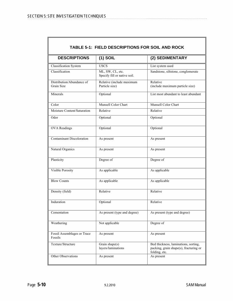
SECTION 5: SITE INVESTIGATION TECHNIQUES
TABLE 5-1: FIELD DESCRIPTIONS FOR SOIL AND ROCK
DESCRIPTIONS (1) SOIL (2) SEDIMENTARY
Classification System USCS List system used
Classification ML, SW, CL, etc. Specify fill or native soil.
Sandstone, siltstone, conglomerate
Distribution/Abundance of Grain Size
Relative (include maximum Particle size)
Relative (include maximum particle size)
Minerals Optional List most abundant to least abundant
Color Munsell Color Chart Munsell Color Chart
Moisture Content/Saturation Relative Relative
Odor Optional Optional
OVA Readings Optional Optional
Contaminant Discoloration As present As present
Natural Organics As present As present
Plasticity Degree of Degree of
Visible Porosity As applicable As applicable
Blow Counts As applicable As applicable
Density (field) Relative Relative
Induration Optional Relative
Cementation As present (type and degree) As present (type and degree)
Weathering Not applicable Degree of
Fossil Assemblages or Trace Fossils
As present As present
Texture/Structure Grain shape(s) layers/laminations
Bed thickness, laminations, sorting, packing, grain shape(s), fracturing or folding, etc.
Other Observations As present As present
Page 5-10 9.2.2010 SAM Manual

SECTION 5: SITE INVESTIGATION TECHNIQUES
TABLE 5-1 (cont.): FIELD DESCRIPTIONS FOR SOIL AND ROCK
DESCRIPTIONS (3) IGNEOUS (4) METAMORPHIC Classification System List system used List system used
Classification Diorite, monzonite, gabbro, dacite, basalt, etc.
Schist, gneiss, quartzite, mylonite, etc.
Minerals List most abundant to least abundant
List most abundant to least abundant
Particle/Grain Size Distribution Relative (include maximum particle size)
Relative (include maximum particle size)
Color Munsell Color Chart Munsell Color Chart
Moisture Content/Saturation Relative Relative
Odor Optional Optional
OVA Readings Optional Optional
Contaminant Discoloration As present As present
Natural Organics Not applicable, unless in fractures Not applicable, unless in fractures
Visible Porosity As applicable As applicable
Blow Counts As applicable As applicable
Density (field) Relative Relative
Induration Relative Relative
Weathering Degree of Degree of
Fossil Assemblages or Trace Fossils
Not applicable As present (remnant)
Texture Euhedral to anhedral, equigranular to porphyritic, vesicular to scoriaceous, crystalline or glassy, etc.
Lineations, foliation, cleavage, cataclastic to mylonitic, etc.
Structure Size and density of fractures, faulting, folding, cleavage, etc.
Size and density of fractures, faulting, folding, cleavage, etc.
Other Observations As present As present
SAM Manual 9.2.2010 Page 5-11
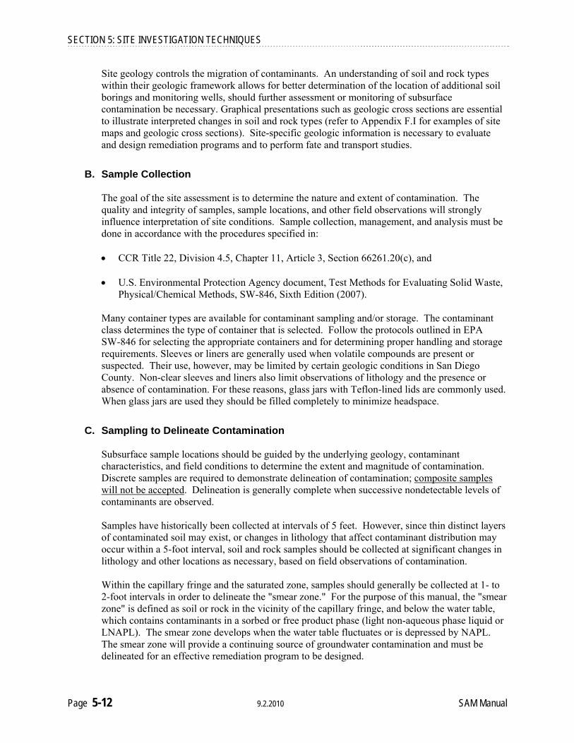
SECTION 5: SITE INVESTIGATION TECHNIQUES
Site geology controls the migration of contaminants. An understanding of soil and rock types within their geologic framework allows for better determination of the location of additional soil borings and monitoring wells, should further assessment or monitoring of subsurface contamination be necessary. Graphical presentations such as geologic cross sections are essential to illustrate interpreted changes in soil and rock types (refer to Appendix F.I for examples of site maps and geologic cross sections). Site-specific geologic information is necessary to evaluate and design remediation programs and to perform fate and transport studies.
B. Sample Collection The goal of the site assessment is to determine the nature and extent of contamination. The quality and integrity of samples, sample locations, and other field observations will strongly influence interpretation of site conditions. Sample collection, management, and analysis must be done in accordance with the procedures specified in:
CCR Title 22, Division 4.5, Chapter 11, Article 3, Section 66261.20(c), and U.S. Environmental Protection Agency document, Test Methods for Evaluating Solid Waste,
Physical/Chemical Methods, SW-846, Sixth Edition (2007).
Many container types are available for contaminant sampling and/or storage. The contaminant class determines the type of container that is selected. Follow the protocols outlined in EPA SW-846 for selecting the appropriate containers and for determining proper handling and storage requirements. Sleeves or liners are generally used when volatile compounds are present or suspected. Their use, however, may be limited by certain geologic conditions in San Diego County. Non-clear sleeves and liners also limit observations of lithology and the presence or absence of contamination. For these reasons, glass jars with Teflon-lined lids are commonly used. When glass jars are used they should be filled completely to minimize headspace.
C. Sampling to Delineate Contamination Subsurface sample locations should be guided by the underlying geology, contaminant characteristics, and field conditions to determine the extent and magnitude of contamination. Discrete samples are required to demonstrate delineation of contamination; composite samples will not be accepted. Delineation is generally complete when successive nondetectable levels of contaminants are observed.
Samples have historically been collected at intervals of 5 feet. However, since thin distinct layers of contaminated soil may exist, or changes in lithology that affect contaminant distribution may occur within a 5-foot interval, soil and rock samples should be collected at significant changes in lithology and other locations as necessary, based on field observations of contamination. Within the capillary fringe and the saturated zone, samples should generally be collected at 1- to 2-foot intervals in order to delineate the "smear zone." For the purpose of this manual, the "smear zone" is defined as soil or rock in the vicinity of the capillary fringe, and below the water table, which contains contaminants in a sorbed or free product phase (light non-aqueous phase liquid or LNAPL). The smear zone develops when the water table fluctuates or is depressed by NAPL. The smear zone will provide a continuing source of groundwater contamination and must be delineated for an effective remediation program to be designed.
Page 5-12 9.2.2010 SAM Manual

SECTION 5: SITE INVESTIGATION TECHNIQUES
Site-specific sampling protocol and sampling strategy must be presented in a workplan (Section 4.III), and should be discussed with DEH staff. Sampling plans often need to be modified during field operations; therefore, details of the sampling and analyses actually performed must be described in the site assessment report.
D. Drilling Techniques for Sample Collection A number of sample collection techniques are used in subsurface investigations. Determining a suitable approach to sampling will depend upon the site accessibility, underlying lithology, and contaminant type. Driven sampling methods that utilize split-spoon samplers, probe/push-sampling techniques, and continuous coring techniques are preferred because these methods allow collection of samples at precise depths. Samples should be collected at least 6 to 18 inches in advance of the drill bit or auger to ensure that undisturbed native material is obtained.
Because the original borehole depth of grab samples collected from auger flights is uncertain, this sampling technique should only be used when driven-sampler and continuous-coring methods are not feasible. When grab samples are being collected, they should be obtained from the lowest flight of the auger and close to the auger stem. Caving or sloughing of the sides of the borehole in softer sediments may further complicate identification of grab sample depths and should be noted on field logs.
Drilling methods that add water, drilling fluids, or other substances into the boring during drilling may contaminate samples, spread contamination, and interfere with analysis for target compounds. A Material Safety Data Sheet (MSDS) must be obtained from the manufacturer for each drilling fluid or additive used at the site. For percussion drilling and other down-hole devices that require lubrication, a pure vegetable oil or other petroleum-free hydrocarbon lubricant must be used. Any substance introduced into the boring or drilling environment should be sampled for comparison analysis of target compounds if cross-contamination is suspected.
The most common drilling and auguring methods are presented in Table 5-2. Actual site conditions may affect the suitability of these methods. Alternative approaches must be discussed with DEH staff.
SAM Manual 9.2.2010 Page 5-13

Cleanup Standards

Initial Screening Levels November 1, 2005
Contaminants* Groundwater (mg/L)
Soil (mg/kg)
Benzene 0.005 0.2 Toluene 1.0 9
Ethylbenzene 0.7 5 Xylenes 10.0 142
Naphthalene 0.7 51 Methyl t-butyl ether (MTBE) 0.2 0.3
Total Petroleum Hydrocarbons (TPH) as gasoline 1 150
Total Petroleum Hydrocarbons (TPH) as diesel 1 500
Oil and Grease or Total Recoverable Petroleum Hydrocarbons (TRPH)
10 1000
Tier 1 Screening Criteria November 1, 2005
Tier 1 Screening Levels are applicable only when the following site conditions are met:
1.) No buildings, property boundaries or utility lines within 30 feet of the highest measured concentration of any contaminant that is greater than the initial screening levels but less than or equal to the Tier 1 screening levels AND, 2.) No water wells or surface water within 500 feet of highest measured concentration of any contaminant that is greater than the initial screening levels but less than or equal to the Tier 1 screening levels.
Contaminants * Groundwater (mg/L)
Soil (mg/kg)
Benzene 0.3 0.9 Toluene 3 25
Ethylbenzene 4 23 Xylenes 10 142
Naphthalene 0.7 51 Methyl t-butyl ether (MTBE) 0.2 0.3
Total Petroleum Hydrocarbons (TPH) as gasoline 10 1500
Total Petroleum Hydrocarbons (TPH) as diesel 10 5000
Oil and Grease or Total Recoverable Petroleum
Hydrocarbons (TRPH) 10 10000

Analytical Methods for Environmental Sampling at Underground Storage Tank Sites in Utah
ANALYTICAL METHODS1
Substance or Product Type
Contaminant Compounds to be Analyzed for Each
Substance or Product Type Soil, Groundwater or Surface Water
Total Petroleum Hydrocarbons (purgeable TPH as gasoline range organics C6 - C10)
EPA 8015B or EPA 8260B
Gasoline
Benzene, Toluene, Ethyl benzene, Xylenes, Naphthalene, (BTEXN) and MTBE
EPA 8021B or EPA 8260B
Total Petroleum Hydrocarbons (extractable TPH as diesel range organics C10 – C28)
EPA 8015B
Diesel Benzene, Toluene, Ethyl benzene, Xylenes, and Naphthalene (BTEXN)
EPA 8021B or EPA 8260B
Oil and Grease (O&G) or Total Recoverable Petroleum Hydrocarbons (TRPH)
EPA 1664A or EPA 1664A (SGT*)
Used Oil Benzene, Toluene, Ethyl benzene, Xylenes, Naphthalene (BTEXN) & MTBE; and Halogenated Volatile Organic Compounds (VOX)
EPA 8021B or EPA 8260B
New Oil
Oil and Grease (O&G) or Total Recoverable Petroleum Hydrocarbons (TRPH)
EPA 1664A or EPA 1664A (SGT*)
Other
Type of analyses will be based upon the substance or product stored, and as approved by the Executive Secretary (UST)
Method will be based upon the substance or product type
Total Petroleum Hydrocarbons (purgeable TPH as gasoline range organics C6 - C10)
EPA 8015B or EPA 8260B
Total Petroleum Hydrocarbons (extractable TPH as diesel range organics C10 – C28)
EPA 8015B
Oil and Grease (O&G) or Total Recoverable Petroleum Hydrocarbons (TRPH)
EPA 1664A or EPA 1664A (SGT*)
Unknown
Benzene, Toluene, Ethyl benzene, Xylenes, and Naphthalene (BTEXN) and MTBE; and Halogenated Volatile Organic Compounds (VOX)
EPA 8021B or EPA 8260B
1 The following modifications to these certified methods are considered acceptable by the Executive Secretary (UST):
• Dual column confirmation may not be required for TPH and BTEXN/MTBE analysis. • A micro-extraction or scale-down technique may be used for aqueous samples, but only for the determination of extractable TPH as diesel range organics
(C10 – C28). • Hexane may be used as an extraction solvent. • *Silica Gel Treatment (SGT) may be used in the determination of Total Recoverable Petroleum Hydrocarbons.
NOTE: The sample preparation method and any modification(s) to a certified method must be reported by the laboratory
Subsurface Investigation, Sampling, and Analytical Requirements
7-1
Utah Division of Environmental Response and Remediation Underground Storage Tank Consultant Certification Manual 2009
CHAPTER 7 Screening/Cleanup Levels for LUST Sites
7. INTRODUCTION__________________________________________________________ The question: “How clean is clean?” is not easily answered. In a perfect world, the answer would be “non-detectable” or “pristine” or “the way it was before you spilled chemicals on it.” In the real world, however, the answer is complex and depends on several factors:
♦ Contaminant type, ♦ Contaminant location, ♦ Contaminant migration potential (fate and transport), ♦ Threat or risk to human health and the environment, ♦ Current and future use of property, and ♦ Economics.
Utah's Department of Environmental Quality, Division of Environmental Response and Remediation (DERR), Leaking Underground Storage Tank (LUST) Section has developed an assessment process to evaluate risks to human health and the environment resulting from petroleum contamination from LUSTs. This process is intended to address cleanup when Maximum Contaminant Levels (MCLs), Initial Screening Levels (ISLs), or other applicable cleanup standards cannot reasonably be achieved and is based on Utah Administrative Code R311-211, Corrective Action Cleanup Standards Policy-UST and CERCLA Sites, referred to as Cleanup Standards Policy (2006). A copy of the Cleanup Standards Policy is provided in this Chapter. A table summarizing MCLs, ISLs, and other applicable standards is included in this Chapter. A summary of Utah’s cleanup levels for petroleum contaminated soil and groundwater can be found on the DERR’s website at www.undergroundtanks.utah.gov/docs/cleanuplevels.pdf. Utah’s risk assessment process is derived from, and is consistent with, the United States Environmental Protection Agency’s (EPA) Office of Solid Waste and Emergency Response (OSWER) Directive 9610.17 (February 24, 1994) (“EPA Directive” entitled Use of Risk-Based Decision-Making in UST Corrective Action Programs). The EPA Directive references the American Society for Testing Materials (ASTM) Standard Guide for Risk-Based Corrective Action (RBCA) Applied at Petroleum Release Sites (ASTM, 1995) which identifies and describes one method of evaluating the risk to human health and the environment posed by multiple constituents in petroleum-contaminated soil, groundwater and air. The ASTM (1995) document provides guidance for evaluating risks at petroleum release sites using a three-tiered approach. The first tier (Tier 1) is a screening process that uses only general hydrogeologic information and conservative assumptions to ensure protection of potential receptors. The second and third tiers require increasingly more accurate site-specific data, as well as increasingly sophisticated contaminant fate and transport modeling, to achieve greater accuracy and certainty in evaluating risks to receptors. The 1995 ASTM document contains the mathematical exposure equations for calculating risk-based screening levels (RBSLs) for a specified target excess risk (TER) limit.

Subsurface Investigation, Sampling, and Analytical Requirements
7-2
Utah Division of Environmental Response and Remediation Underground Storage Tank Consultant Certification Manual 2009
CHAPTER 7 Screening/Cleanup Levels for LUST Sites
Utah has generally adopted the 1995 ASTM method but has modified it into a two-tiered approach for performing risk assessments. Utah’s method is designed to provide systematic and consistent determinations of risk to potential receptors in accordance with the Cleanup Standards Policy. Like the ASTM (1995) approach, Utah’s two-tiered approach requires increasingly more accurate site-specific data and increasingly complex transient contaminant fate and transport modeling with each option upgrade in order to achieve greater accuracy and certainty in evaluating risks to receptors. Utah’s Tier 1 Screening Levels (SLs) are contaminant concentrations in soil and groundwater that are considered “safe to leave in the subsurface” at any site if all of the Tier 1 distance criteria are met. Tier 1 SLs were developed by the DERR using conservative formulas and general Utah-specific (not site-specific) input parameters. Tier 1 distance criteria are distances from contaminated subsurface soil or groundwater to “receptors”. Receptors include wells (municipal, domestic, and irrigation), surface water bodies (lakes, rivers, streams, and canals), utilities (water supply lines, storm drain pipes, and sewer lines), and property lines. In order to use Tier 1 SLs, the contaminated soil and groundwater at the site must be located over 30 feet from utilities and property lines, and over 500 feet from wells and surface water bodies. In most cases, if subsurface contamination is below Tier 1 Screening Levels and the site meets all Tier 1 criteria, then no additional cleanup work is required at the site and the case is closed. A summary of the Tier 1 Screening Process can be found in the DERR’s Guidelines for Utah’s Corrective Action Process for Leaking Underground Storage Tank Sites, October 30, 2005. This guide is available on the DERR’s website at: http://www.undergroundtanks.utah.gov/rbca.htm. Utah’s Tier 2 SLs are developed using site specific input parameters from the site and more realistic (less conservative) formulas than those used to develop the Tier 1 SLs. Details on determining Tier 2 site-specific screening levels (SSCLs) can be found in DERR’s Guidelines for Utah’s Corrective Action Process for Leaking Underground Storage Tank Sites, October 30, 2005. This guide is available on the DERR’s website at: http://www.undergroundtanks.utah.gov/rbca.htm.

Subsurface Investigation, Sampling, and Analytical Requirements
7-3
Utah Division of Environmental Response and Remediation Underground Storage Tank Consultant Certification Manual 2009
CHAPTER 7 Screening/Cleanup Levels for LUST Sites
7.1 FATE AND TRANSPORT OF PETROLEUM HYDROCARBONS IN THE
SUBSURFACE An understanding of contaminant fate and transport processes in the subsurface is fundamental to making informed decisions at leaking underground storage tank (LUST) sites. The behavior of petroleum hydrocarbons in the subsurface is governed by the physical and chemical properties of the contaminants, as well as the site-specific characteristics of the media (soil, groundwater, soil gas) through which the contaminants migrate. Fate and transport mechanisms are complex and the discipline is rapidly evolving. Numerous computer software packages are available to assist in simulating fate and transport processes. In most cases, the objective of computer simulations is to generate numerical models that predict concentrations of petroleum contaminants in soil or groundwater over time. Their success in predicting actual site conditions depends on the availability and reliability of site-specific data including (but not limited to) input parameters which represent soil sorption, dispersion, and biodegradation processes. Computer models are only as reliable as the input parameters on which they are based. Whenever possible, site-specific parameters should be utilized, and a discussion of model assumptions and limitations should always accompany the computer simulations. When valid assumptions are made, computer fate and transport modeling can be a valuable tool for planning subsurface investigations, screening remedial options, or designing corrective action systems. 7.2 DETERMINATION OF RBSL AND SSCL VALUES FOR TOTAL PETROLEUM
HYDROCARBONS (TPH) TPH fractionation is only required when a LUST site has been approved to conduct a risk assessment following RBCA protocols as outlined in Guidelines for Utah’s Corrective Action Process for Leaking Underground Storage Tank Sites. Utah’s Guidelines for TPH Fractionation at Leaking Underground Storage Tank Sites document can be found on the DERR’s website at http://www.undergroundtanks.utah.gov/docs/fractionation.pdf. 7.3 SAMPLE COLLECTION___________________________________________________ Collect a minimum of one environmental sample which is representative of each contaminated medium (e.g., soil and groundwater) and the maximum concentration and composition of the petroleum contamination at the site. For sites where TPH contamination is highly variable in concentration or composition, the user should collect multiple TPH samples at representative locations to ensure a representative analysis by the laboratory.

Subsurface Investigation, Sampling, and Analytical Requirements
7-4
Utah Division of Environmental Response and Remediation Underground Storage Tank Consultant Certification Manual 2009
CHAPTER 7 Screening/Cleanup Levels for LUST Sites
7.4 LABORATORY ANALYSIS________________________________________________ Analyze the sample(s) using EPA Methods 8260B and 8270B. Specify “Utah TPH Fractionation” on the chain-of-custody forms to ensure that the laboratory uses the reporting format specific for TPH fractionation, which differs from a typical 8260B and/or 8270B chemical parameter listing. The laboratory should report concentrations for each of the 10 different TPH fractions shown on the following flowchart. In addition, on the 8260B report, the laboratory should list values for any detectable BTEXN and MTBE. For fractions where the measured concentration is below the method reporting limit, a value of half of the method reporting limit should be used as the representative source area concentration in deriving SSCLs. 7.5 DETERMINATION OF TIER 2 RBSLS FOR EACH TPH FRACTION____________ Fraction-specific RBSL values must be derived for each complete exposure pathway at the site. For each TPH fraction, RBSL values can be calculated for each relevant exposure pathway using the equations provided on Table C-1 of the Tier 2 Guidance Document (Equations C.1 through C.8). Fraction-specific chemical property values and toxicological parameters to be used in the RBSL calculations are provided in Table C-2 of the Tier 2 Guidance Document. 7.6 DETERMINATION OF SSLC VALUES FOR TPH FRACTIONS_________________ Under Tier 2 Options 2 through 4, SSCL values for the individual TPH fractions are developed in the same manner as for any other COCs (e.g., BTEXN and MTBE). Using the chemical property values and toxicological parameter values, a NAF value may be derived for each TPH fraction using the Option 2 through 4 calculation methods. The NAF is then multiplied by the appropriate RBSL value to obtain an SSCL for each complete exposure pathway. The fraction that exceeds its applicable SSCL the most will ultimately drive the cleanup for all the other fractions contained within TPH at the site. 7.7 CONFIRMATION SAMPLING FOR TPH FRACTIONS FOLLOWING TPH-
DRIVEN CLEANUP ACTIVITIES After completing cleanup activities that are driven by the exceedence of the SSCLs for the TPH fraction(s), the user should obtain an appropriate number of environmental samples at representative locations and depths in order to verify the effectiveness of the cleanup at the release site. The same procedures described herein would again be employed for comparison with representative source area TPH fractionation values obtained. During cleanup, the user may elect to obtain samples for TPH fractionation, and BTEXN and MTBE (EPA Method 8020) if applicable, to measure the relative progress of the cleanup activities and to estimate the cleanup duration.

Subsurface Investigation, Sampling, and Analytical Requirements
7-5
Utah Division of Environmental Response and Remediation Underground Storage Tank Consultant Certification Manual 2009
CHAPTER 7 Screening/Cleanup Levels for LUST Sites
Figure 7-1 Utah’s Total Petroleum Hydrocarbon Fractionation & Analytical Method
Relationship
Soil and/or
Groundwater Sample
Gasoline Range Organics (GRO)Using EPA method 8260B
Diesel Range Organics (DRO) Using EPA method 8270B
C9 - C10 Alkyl
Benzenes (1, 3 ,5
Trimethyl benzene)
C5 - C6 Alphatics (Hexane)
C11 - C13 Alkyl
Naphthalenes (Total alkyl
naphthalenes)
C12 - C22 PAHs
(Polynuclear aromatic
hydrocarbons)
C7 - C8
Aliphatics (Heptane)
C9 - C10 Aliphatics
(Nonane)
C11 - C12 Aliphatics (Undecane)
C13 - C16 Aliphatics
(Hexadecane)
C17 - C21
Aliphatics (Heptadecane)
C22 - C35 Aliphatics (Eicosane)
* = Surrogate Chemical used for Toxicity values (RfD) in the RBCA Document.

____________________________________________________________________________________________
State Of Utah
Department of Environmental Quality Division of Environmental Response and Remediation
Leaking Underground Storage Tank (LUST) Subsurface Investigation Report Guide
A Customer Guide to assist Utah owners and operators of underground storage tanks in their investigation of the extent and degree
of petroleum contamination from LUST sites.
December 2009 ________________________________________________________________________________

Subsurface Investigation Report Guide Page 2
A petroleum release has been confirmed at your facility, and screening levels have beenexceeded. You are therefore required to investigate and remediate the release. This publication will guide you through the process of preparing the Subsurface Investigation Report as required under the state-established compliance schedule(s) for releases of petroleumproducts from underground storage tank (UST) systems. A subsurface investigation, to definethe extent and degree of contamination, is required in order to establish site-specific clean-up levels prior to consideration of closing the release site. This Subsurface Investigation Report replaces the former versions known as the “Abatement and Initial Site Characterization Report” and the “Subsurface Investigation Report,” formally required under the “Phase I” and “Phase II Reporting and Remediation Schedules.” The “Corrective Action Plan Report” has been replaced by the “Corrective Action Plan Guide.” The former reporting formats should be discontinued immediately.
TABLE OF CONTENTS SUBSURFACE INVESTIGATION AND CLEAN-UP CHECKLIST.............................. 3FREQUENTLY ASKED QUESTIONS............................................................................... 3
WHY SHOULD I SUBMIT A REPORT?............................................................. 3SHOULD I HIRE A CONSULTANT? .................................................................. 4WHEN DO I SUBMIT THE REPORT? ............................................................... 4HOW DO I FILE THE REPORT? ........................................................................ 4WHAT INFORMATION SHOULD THE REPORT CONTAIN? ..................... 4
REPORT COMPONENTS EXECUTIVE SUMMARY ................................................................................................... 5TABLE OF CONTENTS ...................................................................................................... 5
1 INTRODUCTION ................................................................................................ 52 SITE DESCRIPTION AND MAPS .................................................................... 53 TIER 1 CRITERIA .............................................................................................. 64 NATURE OF THE RELEASE AND ABATEMENT MEASURES ................ 75 METHODOLOGY ............................................................................................... 86 RESULTS.............................................................................................................. 97 CONCLUSIONS AND RECOMMENDATIONS.............................................. 98 REFERENCES AND APPENDICES .............................................................. 109 FREE PRODUCT REMOVAL REPORT (if applicable) ............................... 10
ADDITIONAL INFORMATION
PERMITTING REQUIREMENTS LIST ........................................................... 11SAMPLING PROCEDURES AND REQUIREMENTS .................................... 12TABLE OF ANALYTICAL METHODS FOR SAMPLING ............................ 13FINAL ADVICE.................................................................................................... 14
State of Utah Department of Environmental Quality Division of Environmental Response and Remediation Leaking Underground Storage Tank (LUST) Section 168 North 1950 West, First Floor Salt Lake City, Utah 84116 Telephone: (801) 536-4100 Fax: (801) 359-8853 TDD: (801) 536-4414
The former reporting formats have been replaced and they should not be used any more.

Subsurface Investigation Report Guide
Page 3
The answers to these questions can help get you started.
Subsurface Investigation and Clean-up Checklist The following checklist will provide you with a summary of the steps between discovery of a petroleum release, investigation and remediation (clean-up) of your release and final site closure. It is designed to help you understand the steps involved, to graphically track your progress, and show how near to completion of the process you are.
X Important Steps to Remember
Report the release within 24 hours of discovery to the Division of Environmental Response and Remediation (DERR). Stop the source of the release and prevent the spread of further contamination.
If the leak or release occurred from a tank that is covered by the Utah Petroleum Storage Tank Trust Fund (FUND)*, submit an Eligibility Application for reimbursement of investigation and clean-up costs. Refer to the DERR's publication "Petroleum Storage Tank Fund Claims Packet" for complete eligibility and reimbursement information.
Prepare and submit a "Subsurface Investigation Report" within 90 days of notification from the DERR. Use this guide for preparing the report.**
If free product is found, prepare a "Free Product Removal Report" and include it with your Subsurface Investigation report. Use this guide for preparing your Free Product Removal Report (page 10).
Refer to the “Permitting Requirements List” contained in this guide (page 11) for any applicable reporting or permitting requirements by other regulatory agencies for the release at your facility.
Submit a "Corrective Action Plan", as requested by the DERR, to clean up contamination to established or recommended clean-up levels, or conduct a risk assessment to establish site-specific clean-up levels.
Once work or clean-up at the site is completed as determined by the DERR, request site closure in the form of a "no further action" letter from the DERR.
Frequently Asked Questions Why should I submit a Subsurface Investigation Report? There are two reasons why you must submit this report to the Utah Division of Environmental Response and Remediation (DERR). First, you are required by Utah law to report, control, abate and characterize the release by defining the extent and degree of contamination, and conduct remediation (clean-up) if necessary. And second, it will enable the DERR to help guide you through the investigation and clean-up process to make it as timely, site-specific and cost effective as possible. If information regarding your release site indicates relatively high levels of petroleum contamination, further investigation will help determine if there are risks of contaminating drinking water, indoor air, surface water, sensitive wildlife habitats or other sensitive receptors. This report provides information to help determine these potential risks.
*Even if the tank is not currently on the Fund, the release may be covered by the Fund if the release occurred while the tank was on the Fund and if the tank was on the Fund within the last six (6) months (or one year in some circumstances). If there is any possibility that the release is covered, the eligibility application should be submitted immediately because the claim will be ineligible if it is not submitted on time. See Utah Code §19-6-524. **Depending on the results of your subsurface investigation, more work may be needed at the release site. This additional work may consist of conducting groundwater monitoring, abatement or cleanup activities, additional investigations or other related work.

Subsurface Investigation Report Guide
Page 4
Should I hire a consultant? Utah law requires that starting on January 1, 1996, contractors or environmental consultants must be certified as a “Certified UST Consultant” to perform work at any UST release site. You will need to hire the services of a trained and experienced environmental consultant or contractor to assist you with necessary abatement, investigation and clean-up work and associated reports. Environmental professionals with experience in leaking underground storage tank (LUST) site investigations and clean-ups are available to help you with this work in a timely and cost effective manner. It is in your best interest to get several competitive bids before beginning the work. The DERR has a list of contractors and certified consultants available upon request. The State of Utah does not endorse any consultant or company, but maintains this list of contractors who have indicated an ability to perform the required work for your benefit. When do I submit the report? A Subsurface Investigation Report is due 90 days after receiving this guide from the DERR. Please contact your project manager with any questions regarding your release site or the required report. How do I file the report? Submit your Subsurface Investigation Report to your DERR project manager at:
Utah Department of Environmental Quality Division of Environmental Response and Remediation Leaking Underground Storage Tank (LUST) Section 168 North 1950 West, First Floor Salt Lake City, Utah 84116 (801) 536-4100
You can deliver or submit the report in person to this address or you may send it by mail. What information should the report contain? The remainder of this guide contains the information necessary for putting together the Subsurface Investigation Report. If you use this guide and include the specific information detailed in it, your report will be complete and will minimize the DERR's review and response time. Also, a complete report will help minimize any additional expense or time on your part for the collection of additional data and information.
Depending on the scope of work to be done at your release site, you may need to use a state-certified environmental consultant.

Subsurface Investigation Report Guide
Page 5
Create an at-a-glance summary of your report. A table of contents can work as a checklist assuring the report is complete. Your introduction should include general information about the site. A picture is worth a thousand words. Prepare a good site map!
COMPONENTS OF THE SUBSURFACE INVESTIGATION REPORT Executive Summary The Executive Summary is a brief summary of this report. It may be as brief as one ortwo paragraphs and should provide a summary of the information contained in thisreport and your (or your consultant’s) conclusions and recommendations for achieving clean-up and site closure.
Table of Contents Your Subsurface Investigation Report's table of contents should contain the following:
1. Introduction 2. Site Description and Maps 3. Tier 1 Criteria 4. Nature of the Release and Abatement Measures 5. Methodology 6. Results 7. Conclusions and Recommendations 8. References and Appendices 9. Free Product Removal Report (If applicable)
1 Introduction The Introduction should include the following information:
● Your facility identification number, release site number and locationor address of the release site.
● A brief history of land use at the site including a description of howthe release was determined.
● A brief description of the work completed at the site, and a brief summary of the conclusions and recommendations for further work (ifany) at the site.
2 Site Description and Maps A good site description will help determine potential exposure pathways for petroleumcontamination to reach or impact people or the environment. This section should consist of a vicinity and site map providing a complete graphical description of thefacility and the land surrounding the facility. Each map should be drawn to scale withproper orientation (showing a North arrow) and should be no larger than 11" x 17". This way the maps can be bound into the report. The maps should provide thefollowing information:
● The facility address or location, with an appropriate scale (e.g., barscale with 1 inch = 20 feet, etc.) and North arrow.
● Existing and removed UST systems including piping, dispensers and fill ports.
● Underground utilities including; culinary water supply, sewer or septic systems, natural gas lines, storm drains, power and telephone lines.

Subsurface Investigation Report Guide
Page 6
● Property boundaries, on-site buildings and any adjacent buildings. ● Any excavations showing width, length and depth. ● Any known contaminated areas (square footage or volume if known) ● Location and depths of ALL soil and groundwater samples collected
during any phase of the investigation of this release. Include closure sample locations, confirmation sample locations, soil boring locations, groundwater monitoring well location and other relevant information. Be sure to include depth (feet below grade) of sample collection.
● Location of soil stockpiles, aeration piles, etc. ● Land features surrounding the site including; lakes, rivers, streams,
irrigation canals, wetlands, slope of local land surface, etc.
Identify all sample locations shown on your site map. Make sure your sample numbers and locations are consistent with the identification labels used on the chain-of-custody forms and the laboratory analytical reports.
If the site map becomes cluttered or confusing due to a large number of sample identification labels, you may wish to use more than one sampling map, or use other techniques to identify the sample locations. You may also include additional site maps showing contaminant iso-concentration contours, geologic cross sections and groundwater elevation contours. You should also present the sampling results in a table format so sample data can be easily referenced to sample locations marked on the site map.
3 Tier 1 Criteria This section, “Tier 1 Criteria,” describes the environmental features and possible risks to human health or the environment at the release site. These features help to determine risks presented by your release site and its classification status. Site classification is a dynamic process for prioritizing release sites according to the seriousness of the release. The corresponding response action needed is based on the current and potential degree and severity of hazards to human health or the environment. This process is evaluated on a case-by-case basis and ensures that when maximum contaminant limits are exceeded, appropriate response actions are taken to protect human health and the environment. Site classification is based on the most recent data and reflects current site conditions. Since the risks posed by contamination at any given release site are expected to change as more information is learned about a site, a site may be re-classified. Please provide the following information:
● Describe the current land use at, and surrounding the release site. It is considered residential if a residence is located on, or adjacent to your site in any direction.
● Describe the naturally occurring soil type and the depth and location where the samples were obtained. Unified soil classification (USC) is preferred; however, a geologic field description is acceptable (e.g., gravel, sand, silt, clay, etc.), if done by a qualified person.
● Indicate if you encountered groundwater at your site during UST closure, investigation activities, or obtained groundwater information from other sources. If so, indicate the groundwater depth (in feet) below the ground surface at or near your site.
● Groundwater flow direction can be determined if you have at least three (3) groundwater monitoring wells properly installed at your site. You may also be able to determine groundwater flow direction from other wells installed at a nearby LUST release site. Describe which method you used to determine groundwater flow direction.
Tier 1 Criteria affects the clean-up level and subsequent closure of your site. Be as accurate as possible. Your site classification will help determine if immediate response actions are needed.

Subsurface Investigation Report Guide
Page 7
Site classification is a dynamic process and can change as more information is obtained. Identify the product released and describe where the leak occurred. Have you stopped the release to minimize future problems? On- or off-site soil treatment such as aeration or land farming needs approval from more than one regulatory agency. Don’t forget to take confirmation samples!
● Indicate the distance and estimated depth (in feet) below grade from the source area of petroleum contamination to the following buried utilities; water line, sanitary sewer, natural gas, storm drain, telephone, electrical, other (specify).
● Indicate the distance (in feet) from the source area of petroleum contamination to property lines and buildings (indicate type of building; residential, commercial, industrial, etc.).
● If available, document the water well survey (e.g., Points of Diversion Information) conducted at the release site.
4 Nature of the Release & Abatement MeasuresIn this section, you provide details about the release, including age, condition and contents of the UST. You are also required to perform and report abatement measures to stop the source of contamination and to prevent further releases of contamination. Describe the following:
● Age and condition of the UST system, including piping and tanks, corrosion holes, soil staining or odor, sheen on surface of groundwater or surface water.
● Types and amount of product(s) stored in the USTs, and the type and estimated amount of product released into the environment.
● Cause and location of the release such as the tank, dispenser island, piping, overfills and spills, etc.
● The method(s) used for detecting contamination. ● The location of where the contaminated soil or groundwater was either
properly disposed of, or is currently being stockpiled or stored.
All stockpiled or aerated soils should be managed in accordance with the DERR'S "Guidelines for Disposition and Treatment of Petroleum- Contaminated Soils." Prior to aeration, approval must be obtained from the local health department, the Utah Division of Air Quality and the DERR. Contact your DERR project manager for assistance with these aeration requirements.
● If contaminated soils are over-excavated, or if groundwater is removed
from the release site, confirmation soil or groundwater samples must be taken to confirm that the levels of contamination remaining in-place are at or below established clean-up levels.
● Determine the total volume, contaminant type(s) and concentration(s) of the removed groundwater or soil, and any soil or groundwater contamination remaining in-place.
● Determine the volume, concentration and disposal method or location used for well development or purge water, groundwater, excavation water or other waste water, etc.
● Collect representative environmental samples (soil, groundwater, etc.) to define the nature, extent and degree of the contamination at the site. Information regarding the results of the investigation and plans for future work, if any, should be included in the "Conclusions and Recommendations" section of the report.
● Consult with your DERR project manager or your environmental consultant prior to any confirmation sampling. There may be site-specific requirements necessary for site close-out. See "Sampling Procedures and Requirements" (page 12) for general descriptions of analytical testing requirements for various types of petroleum contamination.
IMPORTANT: You must IMMEDIATELY begin removal of any free petroleum product in excess of ⅛ inch thick. Refer to enclosed Free Product Removal Report (pg 10) for info.

Subsurface Investigation Report Guide
Page 8
5 Methodology This section describes the methods and procedures used to conduct the investigation and should include the following:
● Document that all the proper agencies have been contacted and that all necessary permits or approvals have been obtained. Refer to the list of agencies in the "Permitting Requirements List" (page 11) to determine if you need their involvement or approval.
● Describe all methods of investigation used to define the extent and degree of soil and groundwater contamination. This may include on- or off-site soil borings by drilling or direct-push methods, groundwater monitoring wells, soil vapor surveys, over-excavation, test pits, etc.
● Describe each of the following for all groundwater monitoring well installations: - Method of drilling or other types of placement of wells
(such as digging, backfilling or direct-push techniques). - As-built drawings to document well construction. - How drill cuttings were disposed. - Explain the method used to survey all groundwater wells for
elevation and their relative location. ● Include the following information to document soil conditions and
sampling procedures: - Describe the visual appearance of the soil, including odor,
staining, depth to static water level, thickness of capillary fringe and other field observations made during the investigation and soil sampling.
- Describe native soil type (color, grain size, consistency, hardness, moisture content, etc.) and stratigraphy. This information is collected from soil boring logs, test pits and other methods.
- Describe your field screening methods, analytical sampling results and other relevant sampling procedures.
● Include the following information to document groundwater conditions and sampling procedures: - Describe the visual appearance of the groundwater, odor,
sheen or thickness of free product, depth to groundwater (in feet) below grade, general site conditions and other field observations made while measuring static water level (SWL), purging and sampling the wells.
- Describe method used for purging wells, and how many well casing volumes (total number of gallons) were purged from the well(s).
- Describe how the SWL measurement was determined. - Explain how purge, development or rinsate water generated
from wells was disposed.
These descriptions, methods and rationale are generally referred to as your "standard operating procedures" (SOPs). If your SOPs don't substantially change between different sampling events and reports to the DERR, you don't need to describe them again. Simply refer to the previous report.
Do you need to notify any other regulatory agencies? Refer to the Permitting Requirements List to see if you do. You may need to obtain off-site access agreements to determine the full extent and degree of soil and groundwater contamination. Describe how the subsurface investigation was conducted. You may need to conduct quarterly monitoring for a year or so to determine trends in flow direction, contamination levels and depth to groundwater.

Subsurface Investigation Report Guide
Page 9
Describe the results obtained from your subsurface investigation which should define the extent and degree of soil and groundwater contamination. Refer to “Sampling Procedures and Requirements” in the Additional Information and Resources section at the end of this guide. Include your recommendations for clean-up if additional work is needed, or if site closure is warranted with no further action needed at the site.
6 Results In this section, describe the extent and degree of the contamination from the information you gathered in the field.
● Soil sampling results should include: - A description and documentation of the subsurface geology
of the site, both soil type and stratigraphy. As part of the documentation, you should include boring logs, excavation or cross-section drawings, test pit information, and any other data you collected.
- Include any field screening results. Be sure dates, locations, depths and method(s) for soil screening or sampling are clearly identified.
- A summary of the analytical results developed from laboratory analysis reports should be provided in tabular format. The table should include sample location or other identification number, methods of analyses, depth of sample collection (feet below grade) and results. Copies of the original laboratory analysis reports and chain-of-custody forms must be included in the appendices of the report.
● Groundwater sampling results should include: - A groundwater gradient map showing groundwater
elevations and flow direction. - A summary of the analytical results developed from
laboratory analysis reports should be provided in tabular format. The table should include sample location or other identification number, methods of analyses, depth to water (feet below grade) and results. Copies of the original laboratory analysis reports and chain-of-custody forms must be included in the appendices of the report.
- Dissolved oxygen and any other field parameters (e.g., pH, temperature, redox potential, nitrate, sulfate, etc.) or readings collected in the field, if applicable.
- Site maps showing current chemical concentration results (e.g., iso-concentration maps) for benzene, naphthalene, etc. Show sampling locations and depths using the same sample
ID from the laboratory analytical results table.
7 Conclusions and Recommendations This section allows you the opportunity to summarize the release site conditions obtained during your investigation, the potential risks they present, and to add your perceptions and recommendations on:
● The extent and degree of the contamination, and the volume and highest contaminant concentrations remaining at the release site.
● Whether or not additional work is necessary, underway or planned in the future in order to achieve clean-up goals.
● Further action required on your part for filing claims against the Petroleum Storage Tank Fund for reimbursement of your investigation and clean-up costs.
● Recommendations for DERR action at your site including extensions of deadlines, assistance with resources such as reimbursement of investigation and clean-up costs from the PST Fund, or site closure with no further action required.

Subsurface Investigation Report Guide
Page 10
8 References and Appendices Refer to any outside publications or sources you used for information in preparing this report, or references to documents or reports previously submitted. Additional documents to be added as appendices, include:
● Soil boring logs and stratigraphic cross sections ● Groundwater monitor well construction logs ● Photographs and other supporting information ● Water well surveys (e.g., Points of Diversion Plots) ● Other agency permits or approval letters if applicable
9 Free Product Removal Report Free product can be a severe safety hazard as well as a high risk to human health and the environment. If free phase product is observed at any time (e.g., a ⅛” or more of gasoline, diesel or other petroleum products outside the intended storage system), you must immediately begin source removal. Your free product removal procedures should minimize the spread and migration of contamination into uncontaminated areas and must be removed as completely as possible. This Free Product Removal Report section should include:
● Documentation that you notified the Utah Division of Air Quality at (801) 536-4000 for obtaining approvals or permits related to air emissions from your free product recovery system.
● Documentation that you notified the Utah Division of Water Quality at (801) 538-6146 of free product in contact with groundwater or surface water, and that you obtained the necessary permits or approvals for free product disposal or effluent water discharge related to your free product recovery system.
● Site map and tables showing any information pertinent to free product quantity, thickness, type, extent and other relevant details.
● Construction details and other relevant aspects of the free product removal system such as how much was removed, the disposal location or disposal method used and the current site status.
● If water was extracted in conjunction with free product, sample collection may be necessary in order to characterize the effluent (water) quality and dissolved contamination levels. If so, please include all sampling results in the report. Proper procedures, as detailed in the "Sampling Procedures and Requirements" (page 12), should be followed and documented.
Groundwater shall not be disposed of in a manner placing it in direct contact with the environment or which causes contamination to previously uncontaminated areas.
Include any other additional documentation you feel would be helpful in this investigation, clean-up efforts, or to support the conclusions presented. It may be necessary to file a Free Product Removal Report with your Subsurface Investigation Report.

Subsurface Investigation Report Guide
Page 11
Contact other agencies for necessary approvals or permits.
ADDITIONAL INFORMATION Permitting Requirements List You may need the approval of the following agencies during the course of investigating and remediating petroleum releases. If you have any questions about obtaining approval from other agencies, please contact your DERR project manager at (801) 536-4100. Utah Division of Air Quality (801) 536-4000 If you anticipate emitting hydrocarbon or petroleum vapors into the atmosphere during any phase of the investigation or clean-up, notify Air Quality so they may determine whether an air discharge permit or approval letter is required. Submit documentation of notification and any permits or approvals to the DERR. Utah Division of Water Quality (801) 538-6146 If you know that groundwater has been impacted by a free-phase petroleum product, or that surface waters have been contaminated, notify Water Quality. Any required permits or approvals, including groundwater or surface water discharge, pretreatment or injection, must be obtained prior to implementing corrective action or abatement measures. Documentation of the notification and any permits or approvals obtained should be submitted to the DERR. Utah Division of Solid and Hazardous Waste (801) 538-6170 If you suspect or know the release at your site is a hazardous waste (such as cleaning solvents) or a mixed hazardous/petroleum waste, notify Solid and Hazardous Waste to ensure compliance with permitting, disposal, sampling and other related activities. Utah Division of Water Rights (801) 538-7240 Contact Water Rights for well installation and abandonment procedures for wells greater than 30 feet below grade, and any other permits required by their Administrative Rules for water well drillers. Submit documentation of the notification and any permits or approvals obtained to the DERR. Utah Department of Transportation (UDOT) (801) 965-4000 If you need to work in the public right of way for investigation, sampling or any construction activities, call UDOT, city, county or other appropriate agency for the necessary approvals. Sanitary Sewer District To discharge petroleum contaminated water or waste water to the local sanitary sewer, check your local listing in the Blue Pages for specific numbers listed under "Public Works" or "Sewer," or call the DERR for more information.

Subsurface Investigation Report Guide
Page 12
Local Health Department Contact your local health department or other appropriate agencies (Fire Department, etc.) for any applicable permits, applications or fees they may require for activities related to investigation, construction, corrective action, system operation, disposal or emissions at your release site. These approvals or requirements may vary greatly between different cities or counties. Blue Stakes (800) 662-4111 or (801) 532-5000 Contact Blue Stakes or other appropriate agency for marking underground public utilities prior to any digging or construction activities.
Sampling Procedures and Requirements Follow the guidelines and items in this section to ensure that all types of samples collected are of good integrity, are representative of environmental conditions and contaminant levels. Remember that all samples must be collected by an UST Certified Soil and Groundwater Sampler. ● Describe or document any necessary property access and other permitting
requirements. ● All soil, groundwater, surface water, or other types of environmental
samples must be collected by a Utah certified sampler and analyzed by a Utah certified laboratory. The name and certification number of the sampler and laboratory must be clearly identified.
● Native soil type can be evaluated using Unified Soil Classification methods. Other detailed lithological descriptions may also be necessary.
● Describe subsurface stratigraphy and continuity of strata beneath the site, such as clay, silt or sand lenses, interbedded strata and other features.
● Chain-of-custody protocols and documentation must be maintained and provided for all environmental samples collected.
● All sample identifications, names and numbers should be consistent throughout the chain-of-custody protocol and documentation, laboratory analytical results, site map, data tables and report text.
● Describe sampling methodology, equipment and decontamination procedures.
● Describe the rationale for selecting sample locations and sampled intervals in excavations, test pits, soil/well borings, soil land farms, soil stockpiles or other sample locations. Describe whether sample location determination was based on field instrument measurements, pre-selected intervals or other rationale.
● Describe and/or illustrate depths at which all soil & groundwater samples were collected, show sample locations on a properly scaled and oriented map.
● Identify the sample type(s) collected such as confirmation, grab, composite, headspace, blanks, duplicates, etc., and rationale for their selection.
● Specify the following sampled features and the applicable media sampled, including but not limited to; excavations, test pits, soil borings, soil stockpiles, soil land farms or aeration piles, groundwater monitoring wells, groundwater injection or extraction wells or other types of water wells.
● Provide descriptions of field screening methods and devices used including organic vapor meters or other test methods for detecting the presence of contamination.
● Sampling procedures must be conducted in a manner which minimizes the loss of volatile organic compounds. Describe the methods used to minimize the loss of volatiles and maintain sample integrity, such as zero headspace in sample containers and preserving the sample at 4o Celsius.
● Samples should be immediately delivered to the laboratory. If not, describe the methods use preserve samples and maintain sample integrity within the applicable holding times.
Following these sampling guidelines will help minimize the need to re-sample. It’s important to do it right the first time, so call the DERR with any sampling questions.

Subsurface Investigation Report Guide
Page 13
Don’t forget to take confirmation samples. Consult this table to determine the right testing methods to use during your investigation and other sampling events. Other fuel types such as kerosene, aviation fuel, etc., may be able to be determined by some of these analytical methods.
• Laboratory analytical detection limits must be sufficiently low in order to detect contaminantconcentrations at or below their applicable minimum detection levels or state-established clean-up levels.
• Describe the volume removed (gallons), the method used for purging groundwater wells, and location ormethod used for the disposal of purge water.
• Groundwater well installation and abandonment must be conducted in accordance with the Utah Divisionof Water Rights specifications if the wells are deeper than 30 feet below grade.
• If soil borings or wells are emplaced, the following information if required: - Type of drilling equipment used, and detailed geologic boring logs with an appropriate vertical
scale shown. - As-built drawings showing: number of wells and/or borings; total depth of well or boring; well
construction materials including casing screen type, length, slot size, filter pack material andparticle size;
- Sample locations for soil or groundwater; and, any organic vapor meter measurements. - Type and placement of extraction pumps, if applicable. - Identify the depth of groundwater (feet below grade) encountered at the site during sampling or
investigations. - Describe the volume generated and the procedures used to dispose of drill cuttings, purge water
or other waste materials generated during any phase of the work at the release site. • Confirmation environmental samples (soil, groundwater, etc.) are required any time contaminant is treated
in-place or removed from the subsurface or release site area. • Analytical Methods and Contamination Determination: The following table shows the constituents for
each product type which must be analyzed using approved analytical methods. Other appropriateanalytical methods may be used as approved by the Executive Secretary (UST) for any of the methods outlined below. The analysis of additional constituents may be required as determined by the ExecutiveSecretary (UST).
Analytical Methods for Environmental Sampling at Underground Storage Tank Sites in Utah (July 2004)
ANALYTICAL METHODS1
Substance or Product Type
Contaminant Compounds to be Analyzed for Each Substance or Product Type
Soil, Groundwater or Surface Water
Total Petroleum Hydrocarbons (purgeable TPH as gasoline range organics C6 - C10)
EPA 8015B or EPA 8260B Gasoline
Benzene, Toluene, Ethyl benzene, Xylenes, Naphthalene, (BTEXN) and MTBE
EPA 8021B or EPA 8260B
Total Petroleum Hydrocarbons (extractable TPH as diesel range organics C10 – C28)
EPA 8015B Diesel
Benzene, Toluene, Ethyl benzene, Xylenes, and Naphthalene (BTEXN) EPA 8021B or EPA 8260B
Oil and Grease (O&G) or Total Recoverable Petroleum Hydrocarbons (TRPH)
EPA 1664A or EPA 1664A (SGT*) Used Oil
Benzene, Toluene, Ethyl benzene, Xylenes, Naphthalene (BTEXN) & MTBE; and Halogenated Volatile Organic Compounds (VOX)
EPA 8021B or EPA 8260B
New Oil Oil and Grease (O&G) or Total Recoverable Petroleum Hydrocarbons (TRPH)
EPA 1664A or EPA 1664A (SGT*)
Other
Type of analyses will be based upon the substance or product stored, and as approved by the Executive Secretary (UST)
Method will be based upon the substance or product type
Total Petroleum Hydrocarbons (purgeable TPH as gasoline range organics C6 – C10)
EPA 8015B or EPA 8260B
Total Petroleum Hydrocarbons (extractable TPH as diesel range organics C10 – C28)
EPA 8015B
Oil and Grease (O&G) or Total Recoverable Petroleum Hydrocarbons (TRPH)
EPA 1664A or EPA 1664A (SGT*)
Unknown
Benzene, Toluene, Ethyl benzene, Xylenes, and Naphthalene (BTEXN) and MTBE; and Halogenated Volatile Organic Compounds (VOX)
EPA 8021B or EPA 8260B
. 1 The following modifications to these certified methods are considered acceptable by the Executive Secretary (UST): • Dual column confirmation may not be required for TPH and BTEXN/MTBE analysis. • A micro-extraction or scale-down technique may be used for aqueous samples, but only for the determination of
extractable TPH as diesel range organics (C10 – C28). • Hexane may be used as an extraction solvent. • *Silica Gel Treatment (SGT) may be used in the determination of Total Recoverable Petroleum Hydrocarbons.
NOTE: The sample preparation method and any modification(s) to a certified method must be reported by the laboratory.

Subsurface Investigation Report Guide
Page 14
Final Advice Be sure to check with your DERR project manager or your environmental consultant if you have any questions regarding your sampling program or corrective action plan requirements. Some suggestions or ideas to consider when developing your sampling, operation or maintenance plan may include:
- Take both types of samples (e.g., soil and groundwater) if groundwaterwas encountered during the course of soil sampling.
- Take two or more soil samples in selected locations to better define thevertical extent of contamination. This data will aid in clean-up or closure evaluations.
- Conduct continuous sampling of soil boring(s) or collect multiplesamples per location to better define the native soil type, contaminatedinterval or vertical profile, geological features and related items.
- Upgrade your analytical method(s) to get more complete informationduring the initial sampling events and minimize re-sampling events.
- Have enough budget set aside to be flexible in the number of actualsamples submitted for laboratory analyses, or the number of soilborings or groundwater monitoring wells drilled, etc.
- Check with other regulatory agencies to ensure sampling meets withtheir requirements for waste disposal or other related items.
- Obtain any necessary off-site access agreements or highway easementsfor potential work outside your property boundaries in determining theextent and degree of subsurface soil and groundwater contamination.
- For vapor, air, or any other type of environmental sampling, determinethe appropriate analytical method and sampling procedures prior to field collection.
Some suggestions to make your sampling more cost effective and to provide more information during the initial sampling event(s).

GUIDELINES FOR DISPOSITION AND TREATMENT OF PETROLEUM CONTAMINATED SOILS
FROM UNDERGROUND STORAGE TANK SITES
Improper disposition and aeration of petroleum-contaminated soils from leaking underground storage tank (LUST) sites in close proximity to residential and environmentally sensitive areas could present a direct or potential threat to human health and the environment. This document represents advisory guidelines set by the Executive Secretary (UST) of the Utah Solid and Hazardous Wastes Control Board when soil management activities are proposed at any facility.
As outlined in Utah Admin. Code Section R311-204-2, the Executive Secretary reviews and approves closure plans, which include information concerning management of petroleum contaminated soils. If a closure plan (or corrective action plan for LUST sites) indicates that a specific form of soil management or disposal will be performed at a facility, the Executive Secretary will require additional information concerning this activity. Because of the potential for improper management of petroleum contaminated soils, the following information should be provided to the Executive Secretary (UST) for review*.
GENERAL SOIL MANAGEMENT GUIDELINES AND CONDITIONS FOR CONSIDERATION:
All underground storage tank ownersloperators who are planning to close their tank systems should plan for the possibility that they will be generating contaminated soils during the removal process. Proper disposal of the soil should be arranged before beginning any removal activities to minimize the concerns discussed above. If aeration is not proposed as part of the closure plan, but later proposed following any activity which will probably generate contaminated soil, then the responsible party must immediately take the following actions upon the overexcavation or generation of the impacted soils:
the contaminated soils should be placed on an impermeable liner (to minimize leaching of the contamination into the ground); the contaminated soils should be covered by an impermeable liner (to minimize both emissions of volatile hydrocarbons to the atmosphere, and to limit potential human contact); and, the site should be secured from the general public to minimize any potential exposure.
* A staff member from the UST compliance section will assist you in meeting the UST closrtre requirenrents. I/ petrolerm~ contaminated soils are reported or confirmed at the site, a project manager from the LUST section will be assigned to assist you. Contacting the appropriate person will save time and avoid confusion. If?.ou have questions about what to do. call either section at (801) 536-4100.

Page 2
The proposed soil aeration plan is discussed in more detail below. The following items provide general considerations which must be satisfied or completed prior to submitting the proposal. If the following conditions at a site cannot be met, it is doubtful that approval for the actual aeration would be granted by the Executive Secretary (UST). If that is the case, and you cannot satisfy the following conditions, then you should start making arrangements for the proper disposal of the soil at an acceptable facility.
If you can meet the following conditions, and plan on submitting a proposal as discussed below, and if you have already generated any contaminated soil, i t is important that any stockpiled soil should be properly managed pending either the aeration approval, or other final disposition of the soil.
The ownerloperator or responsible party of the underground storage tank system is responsible for notifying and obtaining approval from the Local Health Department, the Utah Division of Air Quality, and Local Fire Agency prior to any soil management or treatment activity. The Executive Secretary (UST) will require the documentation of these approvals from other agencies prior to considering granting final authorization of any soil treatment activity. In the event that the other agencies do not approve of the aeration plan, or, even if they have approved the plan, but the Executive Secretary (UST) does not approve of the proposed plan, then the owner will be required to dispose of the soil properly at an acceptable disposal facility. It should be noted that these guidelines do not preempt or supersede any other federal, state or local law, ordinance or jurisdiction. If the aeration plan is not approved by any of the agencies involved, including the Executive Secretary (UST), then proper disposal of the contaminated soil at an approved facility will need to occur within 30 days of the disapproval. Contaminated soils should not be placed in direct contact with groundwaterlsurface water or in an area which may impact groundwaterlsurface water. Soils should not be placed near structures, utility conduits, or other conduits (such as irrigation ditches, water wells, or surface/subsurface drainage systems) that may serve as pathways for migration of contamination. Contaminated soils should be placed on level ground, on an impermeable liner, cordoned off, and bermed to reduce the potential health risks and prevent runoff from leaving the site. Contaminated soils should be placed such that the environment cannot be affected or degraded. Contaminated soils should not be placed in close proximity to the general public. The placement of the soils must provide sufficient distance from nearby residences and buildings to prevent potential health risks or nuisance to surrounding populations. The area used for the treatment of the soils should be secured to prevent access by the general public. In addition, the contaminated soils should be covered by an impermeable liner (to minimize both emissions of volatile hydrocarbons to the atmosphere, and to limit potential human contact).
PROPOSAL FOR SOIL MANAGEMENT OR AERATION:
The notification to the DERR must be in the form of a written underground storage tank closure plan, or leaking underground storage tank corrective action plan which is to be submitted for the Executive Secretary's review and approval, disapproval, or conditional approval. The proposal should give specific information about the following:

Page 3
Verification of the approval from the other referenced regulatory agencies. Documentation that the conditions discussed above have been satisfied. The methodology or treatment technology to be used for the soil management activity. The sampling plan to be used to monitor the progress of the soil treatment activities (e.g., frequency of sample collection, type of samples collected, analytical methods to be used, and certified samplers and laboratories to be used). The proposed final disposition (or the final disposal location to be used) of the soil. A vicinity map and site map providing a complete graphical description of the facility and the land surrounding the facility. The maps should be drawn to scale with proper orientation (showing a North arrow) and should be no larger than 1 1" x 17". The maps should provide the following information:
The facility address or location, with an appropriate scale (e.g., bar scale with 1 inch = 20 feet, etc.) and North arrow. Underground utilities (e.g., water supply, sewer or septic systems, natural gas lines, storm drains, power lines, and telephone lines). Property boundaries, on-site buildings, on- and off-site land use, and any adjacent buildings surrounding the property where the soil treatment will occur. Location of soil stockpile(s) and proposed treatment area(s). Land features surrounding the site including; lakes, rivers, streams, irrigation canals, wetlands, slope of land surface, irrigation, agricultural or other types of water wells, etc.
The maximum volume and concentration of the contaminated soils to be treated should be indicated in the proposed plan. If the approved levels of volatile emissions are exceeded during the soil management activity, a revised plan must be submitted to the DERR for approval prior to treatment of the exceeded amounts.
IMPLEMENTATION OF THE APPROVED TREATMENT PLAN:
Any deviation from the plan, which was approved by the Executive Secretary, should be submitted in written form and approved prior to implementation. Progress reports (in regards to their content and frequency of submittals) for the implemented soil treatment technology or plan are to be submitted to the DERR in accordance with the approval letter issued by the Executive Secretary. Once the soil treatment activities are completed, submit a proposal to conduct final confirmation sampling to verify meeting established cleanup levels. Upon meeting cleanup levels, document the same to the DERR by providing the required information as outlined in the approval letter (e.g., sampling, reporting, disposal and other related issues), and request a closure letter for the soil management area. If cleanup levels have not yet been met, additional treatment or work may be required prior to site closure.

Summary of RP 1628
1[490 Summary of API Publication 1MS: A Guide to the Assessment and Remeduhn of U . & F'ebroleum Releases by Peg Chandler, API Marketing Department*
For many years, the American Petroleum Institute (API) has developed approaches to safe- guarding against leaks and spills from underground storage tanks and has published a number of documents that summarize these recommendations, including API Recommended Practices (RPs) 1604,1615,1621, 1631, and 1632. The U.S. Environmental Protection Agency (EPA) cited these five RPs as appropriate standards and guidance documents in its UST regulations.
Recently, API revised another document, RP 1628, A Guide to the Assessment and Remediation of Underground Petroleum Releases (formerly the Spill Cleanup Manuan. The revised RP 1628 provides an overview of proven methods to assess and remediate petroleum-contaminated soil andlor ground water. The following is a summary of the updated RP 1628.
RP 1628 is organized around the phases in which petroleum is commonly found in releases- that is, vapor phase; liquid phase, including residual hydrocarbon; and dissolved phase in ground water. The document discusses:
Fundamental technical concepts, including earth material characteristics, subsurface water characteristics, properties of petroleum, and subsurface migration principles;
Emergency response and initial abatement;
* This article is based upon A Guide to the Assessment and Remediation of Underground Petroleum Releases, A P Z Publication 1628, Second Edition, August 1989. Cost is $16 nonmember/$14 member. AIZ APZ Recommended Practices may be ordered from API Publications, 1220 L St. N. W., Wmhington, D.C. 20005, (202) 682-8375.
Tab 400
Site assessments, including collecting background information, contaminant characterization, and exposure assess- ment;
Site remediation, including liquid recovery, vapor treatment, and ground- water treatment; and
Cleanup objectives.
Fbhmental Technical Concepts A basic knowledge of the subsurface environ-
ment is necessary to assess properly under- ground releases of petroleum. A quick discussion of the most basic concepts and definitions follows.
EarthMatexial- . . In general, earth materials that may be contaminated by petroleum releases include unconsolidated sed- iments Ooose earth materials that result from erosion of bedrock), soils, and fill (any material used to backfill excavated areas such as soil, sand, and pea gravel).
Two physical properties of earth materials that may affect fluid movement through the s u b surface environment are porosity (the ratio of volume of void space to the total volume of material) and permeability (a measure of a material's ability to transmit fluid).
Sub* Water -as. The char- acteristics of subsurface water are also impor- tant. Before a petroleum release occurs, the voids of shaIlow earth materials are occupied with air and water. The distribution of air and water in the subsurface is important to understand (see F'igure 2 for example of air and water distri- bution in the subsurface). The 'unsaturated zone" is found immediately below the land d c e ; its pore spaces contain both water and air. The 'saturated zone" underlies the unsaturated zone; its pore spaces are filled with water. The water table lies between the two zones. The term 'ground water" denotes all water in the saturated zone.
Pmpaties a# Petmleum. Important properties of petroleum (hereafter referred to as "hydrocarbons") include its mobility in soil, which varies with the viscosity and density, and its solubility in water, which varies with the
Undergmnd Storage Tank Guids Jauary 1990 Page 81

Tab 400 Summary of RP 1628
Legend
Sand grain
water
0 Air
F'igum 1 -Di&ibution arf Water and Air in the Subsrrrface
chemical quality of water and the presence of additives in the gasoline itself. Gasoline move- ment in the subsurface is generally the same as water, but other hydrocarbon liquids (e.g., middle distillates and heavier fuel oils) move more slowly.
SubsurEace Migration. Hydrochons can be present in the subsurface in the vapor phase, the liquid phase, and the dissolved phase. In the vapor phase, most vapor exists in void spaces in the unsaturated zone that are not already occupied by water or liquid hydrocarbons.
Page 82
In the liquid phase, hydrocarbons move down- ward by force of gravity, and some horizontal spreading will also occur because of attractive forces between the liquid hydrocarbon and solid granular surfaces.
In the dissolved phase, soluble hydrocarbons are transferred to water until an equilibrium is achieved. Transport in the dissolved phase depends on ground-water velocity, adsorption of the hydrocarbon to soil particles, volatilization to the unsaturated zone, and biodegradation by bacteria. Figure 2 illustrates the vertical distri- bution and degrees of mobility of hydrocarbon phases in earth materials.
January 1990 lhompson Publishing Group. Inc. 1990

Health & Safety

5-1
Utah Division of Environmental Response and Remediation Underground Storage Tank Consultant Certification Manual 2006
CHAPTER 5 Site Safety
GENERAL SITE HEALTH AND SAFETY Health and safety on a LUST site is of paramount importance for numerous reasons including: ♦ Prevents of work-related injuries, illnesses, and property damage. ♦ Prevents of exposure of the public to harmful substances. ♦ Increases overall productivity and maintains project schedules. Petroleum products are toxic, carcinogenic and flammable. Therefore, these products should be handled with a great deal of care. Petroleum products can enter the body through the typical four routes of exposure:
♦ Inhalation ♦ Ingestion
♦ Injection ♦ Skin or eye absorption
Maintaining a safe work environment is essential whether the tasks be soil and groundwater sampling, UST removal, or remediation. All tasks need to be assessed in light of the degree of potential hazard and the possible routes of exposure. This hazard assessment should form the basis of the health and safety plan to be discussed later. Whereas petroleum products may pose a significant health hazard due to chronic health effects, the general safety hazards associated with LUST sites frequently pose much greater risk of acute health effects. HEALTH AND SAFETY REGULATIONS It is important to realize that LUST work is covered by various regulations at the federal level, including the OSHA Hazardous Waste Site Operations and Emergency Response (HAZWOPER) Standard, 29 CFR 1910.120. The work may also be covered by various state and local regulations. These regulations may be triggered depending upon the degree of hazard posed, for example if the UST leaked and there is a significant exposure to airborne contaminants, respiratory protection may be required. Exposure to airborne contaminants is covered by the OSHA Respiratory Protection Standard, 29 CFR 1910.134. If entry into a tank is required, or if the excavation is considered a confined space, the work may be covered by the OSHA Confined Space Entry Standard, 29 CFR 1910.146. Most standards require that the employer: ♦ Develop a written program to address the hazards in a general manner as part of an employer
program, and also site-specific procedures. ♦ Conduct a hazard assessment to identify the site-specific hazards and then respond to them
appropriately. ♦ Provide employee training. ♦ Provide appropriate personal protective equipment. ♦ Establish emergency response procedures.

5-2
Utah Division of Environmental Response and Remediation Underground Storage Tank Consultant Certification Manual 2006
CHAPTER 5 Site Safety
The employer should search the OSHA Web Page at: www.OSHA.gov for guidance on these and other subjects, including specific applicability of the requirements listed below. SPECIFIC HEALTH AND SAFETY REQUIREMENTS The following section describes how to reduce the hazards on a UST site. These are also issues that are covered as requirements under the OSHA HAZWOPER Standard, 29 CFR 1910.120. Training Employees can not be expected to perform site work properly if they are not properly trained. The HAZWOPER standard requires employers to provide 40 hours of hazard training at the time of initial assignment, 8 hours of refresher training annually, and a minimum of 3 days actual field experience under the direct supervision of a trained, experienced supervisor [29 CFR 1910.120 (e)(3) and (4)(i)]. This training must cover items such as: ♦ Components of the Standard ♦ Medical surveillance ♦ Hazard assessment ♦ Personal protective equipment ♦ Site control ♦ Site characterization ♦ Air quality monitoring
♦ Excavation and trenching ♦ Hazard communication ♦ Decontamination ♦ Drum handling ♦ Illumination ♦ Emergency response procedures
This training must then be supplemented by site-specific training at the time of assignment to a project. This is essential to provide employees with the actual hazards to be encountered and the exposure control strategies to be followed. Although the content of the annual refresher training can vary, it should provide a meaningful update of the initial training. Items that might be included: ♦ OSHA news. ♦ The previous year's injuries and illnesses and steps taken to minimize recurrence. ♦ Changes in monitoring equipment. ♦ Review of hazard assessment. ♦ Addressing contractor issues. Additional initial training is required for employees who may perform management or supervisory roles, or emergency response activities. The supervisory worker must attend a least 8 additional hours of specialized training at the time of job assignment. [29 CFR 1910.120(e)(4)]. Emergency response workers shall be trained in how to respond to expected emergencies [29 CFR 1910.120(e)(7)].

5-3
Utah Division of Environmental Response and Remediation Underground Storage Tank Consultant Certification Manual 2006
CHAPTER 5 Site Safety
Medical Surveillance The HAZWOPER Standard requires that certain categories of employees receive physical examinations at a minimum of three milestones: at initial assignment, annually (unless an occupational physician working closely with the company believes that the physical examination could be performed every other year and still sufficiently monitor employee health status), and at termination. The physical examination must be at no cost to the employee. Firms should work closely with an occupational physician that understands the firm's area of work and the hazards that employees are likely to face. The physical examination should then be tailored to address those exposures. If the firm's work involves potential silica exposure such as during drilling, then a chest X-ray should be included. Other items to be considered include spirometry for lung function, blood tests, urine screening, hearing testing, and perhaps drug and alcohol screening, as may be required by the US Department of Transportation. Other tests for "wellness" such as cholesterol may be also included by conscientious employers. There are basically three determinations the physician may provide to the employer: pass, fail, or pass with limitations. As the responses imply, a “pass” response means that the employee may perform the work outlined by the employer to the physician without limitations on activity. A “fail” response indicates that the employee's condition does not allow him/her to perform the assigned duties. “Pass with limitation(s)” indicates that the physician believes that the employee's duties should be limited in some way. It is essential that the employer understand these limitations to be sure that the employee is not directed to overstep these limitations (or overstep them on his or her own). Other professionals such as safety or industrial hygienists may need to be involved in determining permissible activities. Of course, employee relations or human resources professionals may also need to be involved to ensure that the employee's rights are not compromised. UST SITE HEALTH AND SAFETY PLAN The HAZWOPER Standard requires employers working on sites with hazardous substances and wastes to develop site-specific health and safety plans (HASPs). The HASP is composed of various sections that outline the work and the address the associated hazards. The following paragraphs briefly explain the sections of the HASP. An UST HASP should include a discussion of the following topics: General Information General Information should include the name and location of the facility, work plan objectives, and proposed date(s) of work. This section lists the names of all the main project participants. This is a most important reference page in times of emergency as well as during routine business.

5-4
Utah Division of Environmental Response and Remediation Underground Storage Tank Consultant Certification Manual 2006
CHAPTER 5 Site Safety
Planned Site Activities A brief description of planned activities should be included in this section. The HASP should be revised if significant changes in these activities occur. In this section the general scope of work should be briefly described. This should explain the purpose of the work. The tasks to be performed during the work should be listed in the order in which they will occur. This section forms the basis of the hazard assessment. Next to each task, list the hazard and proposed means of avoiding the hazard. This section should be expanded if needed. Site workers should be aware of the possible dangers associated with drilling, excavation, free-product recovery, and groundwater sampling. Contaminant Characteristics List contaminants of concern, type of contaminant, physical and chemical properties, and the hazards it poses to human health and the environment. It is important to consider contaminants that might be emitted by facilities adjacent to the work site. Previous sampling media, e.g., soil, groundwater, air, and the results should be noted. Site Description A site description should include the current and historical use of the site and surrounding area. In this section, issues adjacent to the work site should be described. Keep in mind that these aspects may not only be influenced by the work on the work site; they may also influence the work site. The sites that could be impacted by the work site include receptors, such as neighborhoods, schools, lakes, etc. Potential sources, such as adjacent factories or leaking tanks from other sites might impact the work site. These should not be overlooked because they may influence the ambient conditions being monitored on the work site. Hazard Evaluation and Mitigation This section should include a listing of known visible hazards, man-made or natural, and any unseen-but-suspected hazards. Site workers should be aware of the possible dangers associated with LNAPL recovery and groundwater sampling. All aspects of hazard mitigation pertinent to the site should be addressed. These may include fire and personal exposure to petroleum hydrocarbons or other organic vapors; heat and cold stress; noise; and heavy equipment use. As noted earlier, these hazards may pose the greatest hazards to workers on the site. They should be very carefully considered and precautions to be taken should be described. This section should be expanded as necessary. Also include fire suppression procedures. Site Safety Work Plan The site safety work plan should include a discussion of general safety, worker training, and medical surveillance requirements; and relevant documentation.

5-5
Utah Division of Environmental Response and Remediation Underground Storage Tank Consultant Certification Manual 2006
CHAPTER 5 Site Safety
Excavations and Trenching Excavation and trenching are integral to much of the UST work. Excavations and trenches can pose confined space and fall hazards. Confined space and fall restraint procedures should be included. Shoring regulations must also be addressed to avoid collapsing of the sides. Shoring should be considered even when individuals will not enter the excavation. Depending upon the types of soils, sidewalls can collapse at distances of 5 to 10 feet or more from the edge of the excavation. Competent persons must design shoring plans and in some jurisdictions these plans must be approved and stamped by licensed Professional Engineers. The OSHA informational booklet entitled Excavations, OSHA Publication 2226, (2002), explains ways to protect workers from excavation hazards. The publication on excavations can be located on OSHA’s website at: http://www.osha.gov/SLTC/trenchingexcavation/recognition.html. Personal Protection Equipment A listing and description of the personal level of protection required for each activity or work. The level and types of personal protective equipment (PPE) which will be used to address personal exposures must be described. This section should be specific with respect to makes and model numbers of PPE should be included in this section. A change in on-site conditions may also dictate a change in PPE. Monitoring/Surveillance Equipment This section should include a listing of all monitoring and surveillance equipment to be used at the site with a discussion of exposure and explosive concerns. This portion of the plan should explain how airborne contaminants will be monitored at the site. There are a number of aspects to be considered when developing the air monitoring plan. These include: ♦ Employee exposures within the work (exclusion) zone. ♦ Potential contaminants leaving the exclusion zone or site that could impact adjacent sites. ♦ Airborne contaminants that might enter the site from adjacent facilities. ♦ Note recognized exposure limits and action levels. Describe what will happen if either the
action level or exposure limits are surpassed, e.g., upgrade PPE, evacuate the site, notify regulators, etc.
♦ The types of instruments that will be used and their limitations. ♦ Confined space monitoring issues, if applicable. ♦ Note also the measurement of percent lower explosive limit (LEL) to avoid fire hazards.

5-6
Utah Division of Environmental Response and Remediation Underground Storage Tank Consultant Certification Manual 2006
CHAPTER 5 Site Safety
Decontamination Personnel and equipment decontamination procedures should be addressed in this section. For site personnel, contamination-reduction phases and personal hygiene for site operations, cleanup operations, and soil/groundwater sampling operations would be needed. Decontamination procedures for equipment used during well installation, tank removal, and groundwater sampling should also be addressed. Equipment as well as personnel decontamination should be explained in detail in a stepwise fashion. Do not overlook equipment used to conduct air sampling, or clean-up activities. Note also presence of personal hygiene facilities. Safety Equipment Checklist This section should include a listing of all personal protection, monitoring and surveillance, and decontamination equipment to be used at the site. Any other miscellaneous equipment that may be needed and used on site should also be listed. Site Safety Briefing Attendance Sheet This section will document the personnel assigned to be on site and personnel from agencies, utilities, or other companies who have read, reviewed, or attended the on-site safety briefing. The sheet should include the date and time of the briefing and the individual conducting the meeting, and the name and company of each attendee. All subcontractors and clients involved in the operation should be included. It is helpful to obtain and include cellular phone numbers as well as traditional telephone numbers. Documentation of proper training and medical surveillance should also be obtained. Investigation-Derived Waste Disposal This section should discuss the disposal procedures for all drill cuttings, soil, wastewater, and disposable protective clothing generated during site operations. It would also be appropriate to describe the disposition of decontamination water and any other special concerns. This section must describe the types of waste expected to be generated from the site work, be they solid or liquid. Note the types of containers to be used. It would be appropriate to list the waste haulers and facilities to which the waste will be sent. Temporary staging areas and precautions can also be included in this section. Emergency Information Emergency information should include applicable phone numbers, names, and addresses of local and emergency resources; and emergency contacts including CHEMTREC, National Response Center, and RCRA Hotline. Any work limitations and required notification should also be discussed.

5-7
Utah Division of Environmental Response and Remediation Underground Storage Tank Consultant Certification Manual 2006
CHAPTER 5 Site Safety
Evacuation/Emergency Response Plan This section should be clearly labeled to allow for quick reference in the event of an emergency. One should be very clear about how evacuation would take place. Written as well as pictorial directions must be included. These directions must be tested prior to starting the project to be sure they “work.” The locations of hospitals, shelters, and barriers to evacuation such as fences, security stops, one-way streets all should be shown and discussed in the HASP. Attachments The health and safety plan should include a map to the nearest medical facility. Forms and other relevant information should be attached to the HASP. This may include material safety data sheets (MSDSs), injury investigation, air and groundwater sampling forms, site audit checklists, site equipment checklists, daily safety meeting agenda and minutes forms, etc. SAFETY MEETINGS Several meetings should be planned to discuss safety. These need not necessarily be stand-alone meetings. These may be incorporated into other job meetings. In fact, this is encouraged so that workers see safety as an integral part of production and not something extra to be discussed if there is time. These meetings are described below: Pre-Start-up Meeting This meeting should be used to discuss all aspects of the project well in advance of the start. This allows time for details to be worked out and additional safety equipment to be obtained if necessary. Special attention should be given to working out the personnel who will be responsible for enforcing safety and attending to health and safety issues at the site. Note who will be contacted in the event of an emergency. Start-up Meeting This meeting, often held on the day the job starts or day before, discusses the final safety staff and contacts, describes the emergency response procedures, lays out the PPE, air monitoring and other relevant issues. Daily Meetings A safety meeting should be held at the beginning of every day the project continues. The scope of the day’s work should be described along with the associated hazards and safety precautions. This offers workers the opportunity to ask questions before proceeding with work.

5-8
Utah Division of Environmental Response and Remediation Underground Storage Tank Consultant Certification Manual 2006
CHAPTER 5 Site Safety Project Close-out Meeting
Projects that last several weeks should have a project close-out meeting to discuss issues that have occurred during the course of the job. This meeting gives participants the opportunity to discuss how to improve safety and general work performance on future jobs. INCIDENT INVESTIGATION All companies should have a program to avoid work-related injuries and illnesses. This program should include the writing of standard operating procedures and job safety analyses. These documents should be used as training tools to teach employees the hazards of doing work and how to avoid them. Employees should be encouraged by training to stop before they begin each task in the field and consider potential hazards and how to avoid them. Companies should investigate “near misses” with the same intensity as actual incidents because the next time the “near miss” might in fact be an incident. This approach tends to improve procedures and practices so that “near misses” are prevented. If all “near misses” were eliminated, then actual incidents would be all but avoided in their entirety. In the event of an incident, whether property damage or personal injury, the investigation must focus on establishing the route cause of the incident. It should not focus on placing blame as this is usually an ineffective means of avoiding similar incidents in the future. Nearly all incidents occur as a result of insufficient training, tools, time management, motivation, or in rare situations.