Embed Size (px)
Citation preview

NASA Contractor Report 198247
!
//
Using the HARV Simulation _Aerodynamic Model to DetermineForebody Strake AerodynamicCoefficients from Flight Data
Michael D. MessinaLockheed Martin Engineering & Sciences CompanyHampton, Virginia
.\
ContractNASl-19000
December 1995
LIBRARYCOPY
INational Aeronauticsand I JAN3 0 1996SpaceAdministration
!
. LangleyResearchCenter [Hampton,Virginia 23681-0001 LANGLEYRESEARCHCENTERLIBRARYNASA
HAMPTON,VIRGINIA
https://ntrs.nasa.gov/search.jsp?R=19960012499 2018-08-30T15:49:25+00:00Z


3 1176 01423 8159"1 r
Acknowledgments
The author thanks Kenneth P. Lawson, a George WashingtonUniversity graduate student working in the Vehicle Dynamics
• Branch, for his collaboration during the development and checkout ofthe tools needed to perform this analysis.

Overview
A method to determine the aerodynamic increments (rolling,pitching, and yawing moments, C1, Cm, Cn, respectively) for theforebody strake controllers added to the F/A-18 HARV aircraft was "_developed to validate the forebody strake aerodynamic model. Theforebody strake aerodynamic model developed from data collected inthe Langley 30x60 wind tunnel is implemented in all F/A-18 HARVsimulations (Reference 1). The method described in this report isintended to present an overview of a process developed to extractthe forebody aerodynamic increments. This report does not showhow to run various simulation tools and does not present resultsbecause data were still being collected and analyzed at the time ofwriting.
The technique is to use attitude rates, surface position, andaircraft state information from flight data to calculate rotationalaccelerations using the simulation aerodynamic model. Theaccelerations are compared with flight data computed estimates toform a difference or error between the model and flight test. Theerror is then used to compute aerodynamic coefficient errors, whichare summed with the model calculation. The summation results inan estimate of the aerodynamic contributions due to the forebodystrakes. The forebody strake aerodynamic coefficients are correct tothe extent that the basic F/A-18, HARV specific, and thrust vectorcontrol system increments are accurate.
Simulation Calculation of Rotational Accelerations
The F/A-18 HARV simulation aerodynamic model sums theaerodynamic increments from individual models to calculate totalaerodynamic increments. The aerodynamic coefficients forCI, Cm, and Cn are computed as follows:
C1Total = C1Low + CIHigh + C1HARV + CITVCS + CIFS
CmTotal = CmLow + CmHigh + CmHARV + CmTVCS + CmFS (1)
CnTotal = CnLow + CnHigh + CnHARV + CnTVCS + CnF S -_
where the subscripts reflect the following definitions:
.

Total = total increment. • ,, .Low = low angle of attack (<40°) basic F/A-18 incrementHigh = high angle of attack (>40°) basic F/A-18 incrementHARV = HARV specific increments
• TVCS = thrust vector control system incrementFS = forebody strake increment
Once the total aerodynamic coefficients are computed, the roll,pitch, and yaw moments at the aerodynamic reference center arecalculated from the aerodynamic model as follows:
Laero = qSbC1Total
Macro = qSc CmTotal (2)
Naero = qSbCnTotal
where _ = dynamic pressureS = reference wing areab = reference wing spanE = mean aerodynamic chord
Moments introduced by the center of gravity (c.g.) shift fromthe aerodynamic reference are computed and used to adjust theaerodynamic moments. In order to calculate the moment shift, theforces at the aerodynamic reference are needed and are computed asfollows:
FxAR = qS{-CDTotal cOs(0_) + CLTotal sin(a)}
FyAR = 98 CYTota 1 .(3)
FzAR = qS{-CDWotal sin(O0 -- CLWotalcOs(O0}
where CDTotal = total drag increment
CLTotal = total lift increment
CYTota1 = total side force incrementCZ = angle of attack
• The force total increments (CDTotal, CLTotal, and CYTotal) arecomputed in a fashion similar to the calculation of moments shown inequation (1).
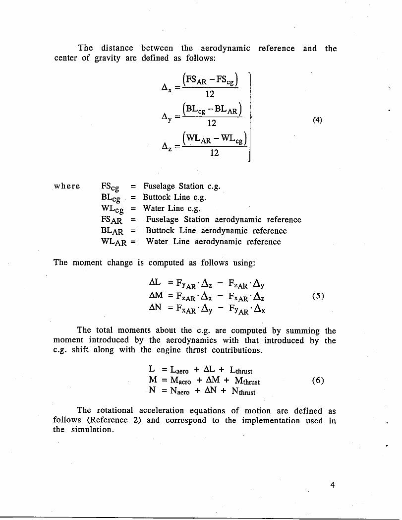
The distance between the aerodynamic reference and thecenter of gravity are defined as follows:
(FSAR - FSeg)m x _
12
(BLcg- BLAR)Ay = 12 (4)
12
where FScg = Fuselage Station c.g.BLcg = Buttock Line c.g.WLcg = Water Line e.g.FSAR = Fuselage Station aerodynamic referenceBLAR = Buttock Line aerodynamic referenceWLAR = Water Line aerodynamic reference
The moment change is computed as follows using:
AL = FyAR.Az - FzAR'Ay
AM = FzAR'Ax -- FxAR'Az (5)
AN = FxAR•Ay - FyAR"Ax
The total moments about the c.g. are computed by summing themoment introduced by the aerodynamics with that introduced by thec.g. shift along with the engine thrust contributions.
L = Laero + AL + LthrustM = Macro + AM + Mthrust (6)
•N = Naero + AN + Nthrust
The rotational acceleration equations of motion are defined asfollows (Reference 2) and correspond to the implementation used in __the simulation.
4

L + Ri2.(q:(RI5-p--RI6.r + p) + "N-N-)RIl.q.r +Ixx lzz
= 1- RI2. RI6
• _1 = RI3.r-p + RI4.(r 2 - p2) + M (7)IyyN
• i" = RI5.p.q + RI6.(p - q.r) +Izz
where p = body axis roll rateq = body axis pitch rater = body axis yaw rateIxx = roll moment of inertiaIyy = pitch moment of inertiaIzz = yaw moment of inertiaIxz = roll-yaw cross coupling product of inertia
RI1 Iyy - Izz RI4 IxzIgx Iyy
RI2 =mIxz RI5 = Ixx - IyyIxx Izz
RI3 - Izz - Ixx RI6 = Ix---ZzIyy Izz
Flight Estimates of Rotational Accelerations usingAerodynamic Model
An estimate of the rotational accelerations of the aircraftduring flight testing can be made by using the simulationaerodynamic model. The estimate is as accurate as the aerodynamicmodel, since all aerodynamic models were developed with windtunnel data only. In order to estimate the rotational accelerations ofthe F/A-18 HARV during flight, the simulation aerodynamic model isrun open loop. This involves using flight data to drive allaerodynamic model inputs over time in place of parameterscalculated in the simulation. The flight data inputs to drive thesimulation aerodynamic model are defined below with the
• instrumentation parameter names from flight data shown inparenthesis:
5
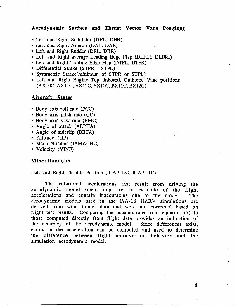
Aerodynamic Surface and Thrust Vector Vane Positions
• Left and Right Stabilator (DHL, DHR)• Left and Right Aileron (DAL, DAR)• Left and Right Rudder (DRL, DRR) --• Left and Right average Leading Edge Flap (DLFLI, DLFRI)• Left and Right Trailing Edge Flap (DTFL, DTFR)• Differential Strake (STPR - STPL)• Symmetric Strake(minimum of STPR or STPL)• Left and Right Engine Top, Inboard, Outboard Vane positions
(AX10C, AX11C, AX12C, BX10C, BX11C, BX12C)
Aircraft States
• Body axis roll rate (PCC)• Body axis pitch rate (QC)• Body axis yaw rate (RMC)• Angle of attack (ALPHA)• Angle of sideslip (BETA)• Altitude (HP)• Math Number (IAMACHC)• Velocity (VINF)
Miscellaneous
Left and Right Throttle Position (ICAPLLC, ICAPLRC)
The rotational accelerations that result from driving theaerodynamic model open loop are an estimate of the flightaccelerations and contain inaccuracies due to the model. Theaerodynamic models used in the F/A-18 HARV simulations arederived from wind tunnel data and were not corrected based onflight test results. Comparing the accelerations from equation (7) tothose computed directly from flight data provides an indication ofthe accuracy of the aerodynamic model. Since differences exist,errors in the acceleration can be computed and used to determinethe difference between flight aerodynamic behavior and thesimulation aerodynamic model.
6

Flight Rotational Accelerations From Flight Test Data
The flight rotational accelerations can be calculated bydifferentiating the measured body axis rotational rates .recorded
• from flight. The rotational accelerations are differentiated by usinguser-defined Matlab functions written by Keith D. Wichman of
• NASA-Dryden Flight Research Center. The user-defined Matlabfunctions are called director.m, firdiff.m, and diffit.m and areincluded in Appendix A of this report. Additional Matlab intrinsicfunctions are utilized along with additional user-defined functions toread and write files in the Dryden GetData compatible formats(Reference 3).
By using the rotational accelerations from flight along withthose estimated from the aerodynamic model, an acceleration errorcan be defined as follows:
12error = 12flight -- 12mode1
(lerror = Clflight- Clmodel (8)i:error = i:flight -- i:rnodel
The error in the rotational accelerations represents the error inthe aerodynamic model plus some contribution due to errors in themeasured parameters.
Calculation of Forebody Strake AerodynamicCoefficients
By manipulating equation (7) to solve for the rotationalmoments L, M, N, and substituting the rotational acceleration errorsin equation (8), the following equations for the moment error can beformed:
Lerror = Perror" (Ixx + RI6. Ixx - RI6. Ixz) -/:error" IxxMerror = ClerrorIzz (9)Nerror = (terror - Perror"RI6)"Izz
Note that all rotational rate terms shown in equation (7) cancelbecause p, q, and r from flight are the same as those used to drive
• the aerodynamic model open loop. Therefore, no errors exist due tothe rotational rates and were neglected in equation (9).
7
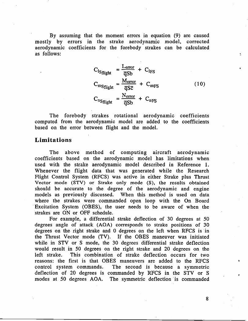
By assuming that the moment errors in equation (9) are causedmostly by errors in the strake aerodynamic model, correctedaerodynamic coefficients for the forebody strakes can be calculatedas follows:
Lcrror
C1sflight - _Sb + C1FS
Men'or
Cmsflight- _S_ + CmFS (I0)
Nerror
Cnsflight - _Sb + CnFS
The forebody strakes rotational aerodynamic coefficientscomputed from the aerodynamic model are added to the coefficientsbased on the error between flight and the model.
Limitations
The above method of computing aircraft aerodynamiccoefficients based on the aerodynamic model has limitations whenused with the strake aerodynamic model described in Reference 1.Whenever the flight data that was generated while the ResearchFlight Control System (RFCS) was active in either Strake plus ThrustVector mode (STV) or Strake only mode (S), the results obtainedshould be accurate to the degree of the aerodynamic and enginemodels as previously discussed. When this method is used on datawhere the strakes were commanded open loop with the On BoardExcitation System (OBES), the user needs to be aware of when thestrakes are ON or OFF schedule.
For example, a differential strake deflection of 30 degrees at 50degrees angle of attack (AOA) corresponds to strake positions of 30degrees on the right strake and 0 degrees on the left when RFCS is inthe Thrust Vector mode (TV). If the OBES maneuver was initiatedwhile in STV or S mode, the 30 degrees differential strake deflectionwould result in 50 degrees on the right strake and 20 degrees on theleft strake. This combination of strake deflection occurs for tworeasons: the first is that OBES maneuvers are added to the RFCS "-control system commands. The second is because a symmetricdeflection of 20 degrees is commanded by RFCS in the STV or Smodes at 50 degrees AOA. The symmetric deflection is commanded
8

by RFCS when the strakes are active to eliminate a control reversalassociated with differential strake deflections less than 30 degrees.The symmetric strake deflections follow a schedule of 1 degree ofsymmetric strake deflection per degree of AOA starting at 30
• degrees. The maximum symmetric strake deflection of 30 degrees isreached at 60 degrees AOA. When the strakes follow the symmetricdeployment they are considered ON schedule (Reference 4). The 50degree and 20 degree deflections on the right and left strakepositions would only occur briefly when RFCS is in the STV or Smode, since closed loop feedbacks would adjust the strake commandsin response to the OBES inputs. For this reason all OBES differentialstrake maneuvers are run with the control laws in TV mode. Thismeans that the symmetric schedule built into the RFCS control lawswhen strakes are active will not be followed and, therefore, thestrakes can be OFF schedule.
The strake aerodynamic model assumes the strakes will be ONschedule. At 50 degrees AOA, the symmetric deflection is 20 degreesas previously mentioned, and a differential deflection of 30 degreeswould result in a right and left strake position of 35 and 5 degreesrespectively when RFCS is in STV or S mode. The wind tunnel dataimplemented in the strake aerodynamic model is based on 35 and 5degree strake positions for the right and left strakes respectively.Using flight data collected for an OBES run with 30 degreesdifferential strake command at 50 degrees AOA, 30 degrees on theright strake and 0 degrees on the left would mean the strakes areOFF schedule. This results in deflections that cannot be supported bythe strake aerodynamic model. Therefore, flight test data used tocalculate aerodynamic coefficients when the strake deflections arecommanded by OBES result in deflections that cannot occur becauseof the symmetric schedule built into the strake aerodynamic model.The flight coefficients calculated in equation (10) will be correct, butcannot be compared directly with C1FS, CmF S, and CnFS from thestrake aerodynamic model since these results are computed OFFschedule.
9

Conclusion
The method described in this report to extract forebody strakecoefficient increment provides a tool to analyze flight data. This toolhas been used to support flight tests of the F/A-18 HARV with theActuated Nose Strakes for Enhanced Rolling control laws. Thismethod is in use to validate the 30x60 wind tunnel model that hasbeen implemented in F/A-18 HARV simulations.
10
REFERENCF_S
1. Messina, M. D.; Strickland, M. E.; Hoffler, K. D.; Carzoo, S. W.;Bundick, W. T.; Yeager, J. C.; Beissner, F. L.: F/A-18 High Angle
" of Attack Research Vehicle Simulation Modifications to Assistthe Design of Advanced Control Laws. NASA TM-110216,
' August 1995.
2. Etkin, Bernard: Dynamics of Atmospheric Flight. Wiley andSons, Inc. 1972.
3. Maine, R. E.: Manual for GetData, Version 3.1. NASA TM-88288,1987.
4. Bacon, B. J.; Davidson, J. B.; Hoffler, K. D.; Lallman, F. J.; Messina,M. D.; Murphy, P. C.; Ostroff, A. J.; Proffitt, M. S.; Strickland, M.E.; Yeager, J. C.; Foster, J. V.; Bundick, W. T.: DesignSpecificationfor a Thrust-Vectoring, Actuated-Nose-Strake Flight ControlLaw for the High-Alpha Research Vehicle, NASA TM-110217,1996.
11

APPENDIX A - Matlab User Defined Functions
director.m
% Read input file, this file contains the flight data body axis% aircraft rates. (pcc - Roll Acceleration, qc - Pitch% Acceleration, RMC - Yaw Acceleration)
!
gdload('temp.cmp3')
% Get bn coefficients to be used in the low-pass filter.
N = 24;wb=I/6;[bn] = 80.*firdiff(N,wb);
% Differentiate the signal.
[pdot] = diffit(bn,pcc,time);pdf=filter([0.1,0.1],[l.0,-0.8],pdot);pdf=filtfilt([0.1,0.1],[l.0,-0.8],pdot);
[qdot] = diffit(bn,qc,time);qdf=filter([0.1,0.1],[l.0,-0.8],qdot);qdf=filtfilt([0.1,0.1],[l.0,-0.8],qdot);
[rdot] = diffit(bn,rmc,time);rdf=filter([0.1,0.1],[l.0,-0.8],rdot);rdf=filtfilt([0.1,0.1],[l.0,-0.8],rdot);
% Write output file which contains the accelerations before and% after filtering along with the aircraft rates for reference% information only. The flight rotational accelerations pdf,% qdf, and rdf are the only ones in determing the forebody strake% aerodynamic coefficients.
gdwrite('temp_rates.cmp3 cmp3', 'time pdf qdf rdf pdot qdot rdotpcc qc rmc');
12
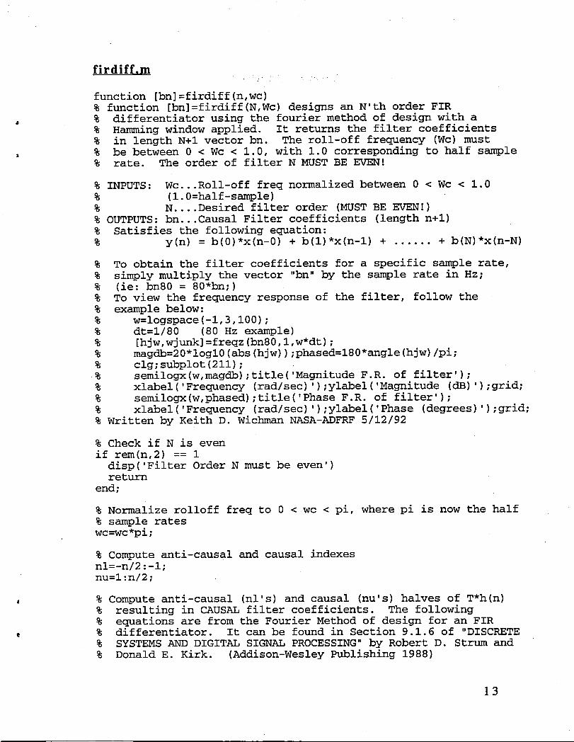
firdiff.m
function [bn]=firdiff(n,wc)% function [bn]=firdiff(N,Wc)designs an N'th order FIR% differentiator using the fourier method of design with a% Hamming window applied. It returns the filter coefficients% in length N+I vector bn. The roll-off frequency (Wc) must% be between 0 < Wc < 1.0, with 1.0 corresponding to half sample% rate. The order of filter N MUST BE EVEN!
% INPUTS: Wc...Roll-off freq normalized between 0 < Wc < 1.0% (l.0=half-sample)% N....Desired filter order (MUSTBE EVEN!)% OUTPUTS: bn...Causal Filter coefficients (length n+l)% Satisfies the following equation:% y(n) = b(0)*x(n-0) + b(1)*x(n-l) + ...... + b(N)*x(n-N)
% To obtain the filter coefficients for a specific sample rate,% simply multiply the vector "bn" by the sample rate in Hz;% (ie: bn80 = 80*bn;)% To view the frequency response of the filter, follow the% example below:% w=logspace(-l,3,100);% dt=i/80 (80 Hz example)% [hjw,wjunk]=freqz(bn80,l,w*dt);% magdb=20*logl0(abs(hjw));phased=180*angle(hjw)/pi;% clg;subplot(211);% semilogx(w,magdb);title('MagnitudeF.R. of filter');% xlabel('Frequency (rad/sec)');ylabel('Magnitude (dB)');grid;% semilogx(w,phased);title('Phase F.R. of filter');% xlabel('Frequency (rad/sec)');ylabel('Phase(degrees)');grid;% Written by Keith D. Wichman NASA-ADFRF 5/12/92
% Check if N is evenif rem(n,2) == 1disp('Filter Order N must be even')return
end;
% Normalize rolloff freq to 0 < wc < pi, where pi is now the half% sample rateswc=wc*pi;
% Compute anti-causal and causal indexesnl=-n/2:-l;nu=l:n/2;
, % Compute anti-causal (nl's) and causal (nu's)halves of T*h(n)% resulting in CAUSAL filter coefficients. The following% equations are from the Fourier Method of design for an FIR
, % differentiator. It can be found in Section 9.1.6 of "DISCRETE% SYSTEMS AND DIGITAL SIGNAL PROCESSING" by Robert D. Strum and% Donald E. Kirk. (Addison-WesleyPublishing 1988)
13
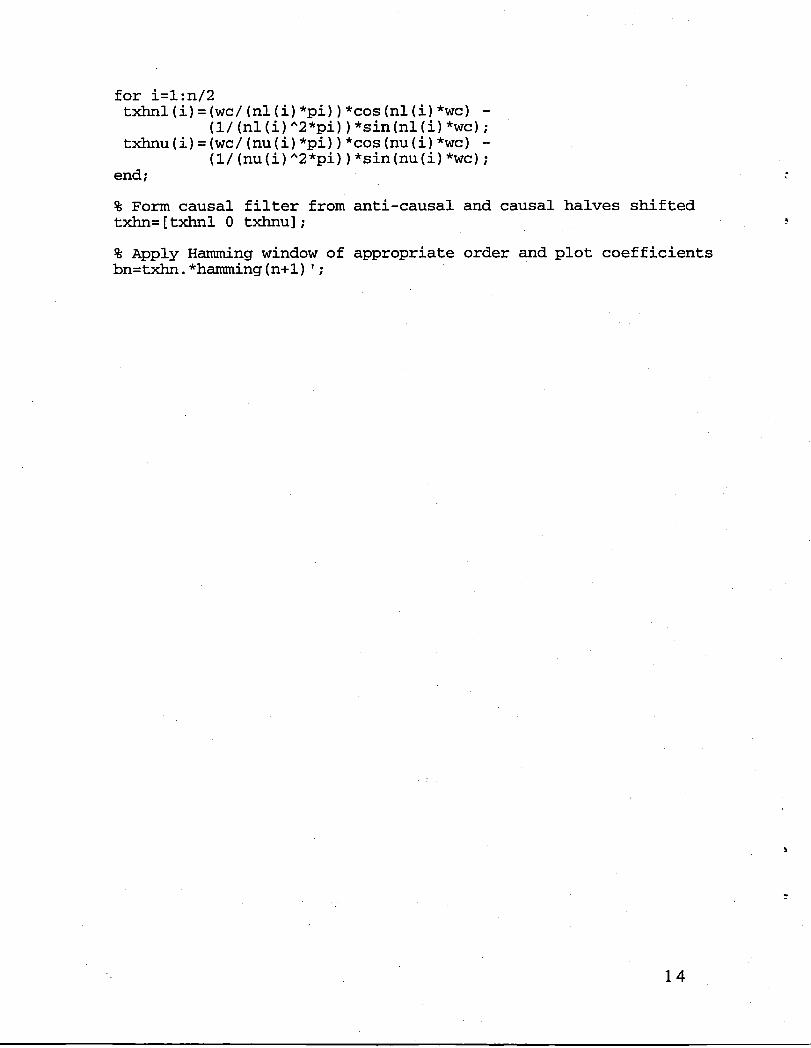
for i=l:n/2txhnl(i)=(wc/(nl(i)*pi))*cos(nl(i)*wc) -
(i/(nl(i)̂ 2*pi))*sin(nl(i)*wc);txhnu(i)=(wc/(nu(i)*pi))*cos(nu(i)*wc) -
(1/(nu(i)̂ 2*pi))*sin(nu(i)*wc);end;
% Form causal filter from anti-causal and causal halves shiftedtxhn=[txhnl 0 txhnu];
% Apply Hamming window of appropriate order and plot coefficientsbn=txhn.*hamming(n+l)';
14

diffit.m
function [sigdotout]=diffit(bn,sigin,time)% function [sigdotout]=diffit(bn,sigin,time)
• % This function computes the differentiated value (sigdotout)% of an input signal (sigin)using the specified FIR filter% numerator (bn).(filterorder N => N+I bn's)% INPUTS: bn.....CAUSAL filter coefficients (bn MUST BE ODD #)% sigin..Input signal to be differentiated% time..Timevector corresponding to input signal% OUTPUTS: sigdotout..Computedderivative of signal% NOTE: bn takes the form:% y(n) = b(0)*x(n-0) + b(1)*x(n-l) + .... + b(N)*x(n-N)% The output signal is shifted by N/2 to ensure ZERO phase shift% induced, ie: a NON-CAUSAL filter. This results in N/2% corrupted terms at the end.% Written by Keith D. Wichman NASA-ADFRF 5/12/92
% Determine Filter Order (bn has N+I terms for Nth order)
n=length(bn)-l;
% Determine input signals length
long=length(sigin);
% Pad end of sigin with reflection of N/2 terms
for i=l:n/2padend(i)=sigin(long-i);
end;sigin=[sigin; padend'];
% Compute signal derivative and discard N/2 terms to make% non-causal (0 phase)
sigdotout=filter(bn,l,sigin);sigdotout=sigdotout(n/2:long+n/2-1);
return
15

"°i_
J
_oJ
FormApprovedREPORTDOCUMENTATIONPAGE OMBNo.0704-0188
Pul:4=cfef)orlnngDur0enformis ¢olk_on ofinfom_a,onisest_alKI to ave(age1hour¢eqres,o_tse,mcluO=ngme I=_eforrah'w,w_ _. mrch_n9oxistin9'_ Iomcm.gab'Nm'_gand maintainingmedataneeded,and €oming _ rev_vv_gIf_ co*lechonot _totma,o_ _ commentsn_sn_ngmS _ eswnateota,'tyo_ a_.s_._of t_s Davis
HKlhway.Sudo1204. A.'lmglon.VA 2,2202-4302.andtotheOffer;ofManagementandBuDget.Pl_e,'v,o_ _ _role¢l_u*'u,Pu_1° mgtcn.n
1. AGENCYUSE ONLY (Leave INank) 2. REPORTDATE 3. REPORTTYPEANDDATESCOVERED
December1995 ContractorReport
4. TITLEAND SUBTITLE 5. FUNDINGNUMBERS .,
Usingthe HARVSimulationAerodynamicModelto DetermineForebody C NAS1-19000StrakeAerodynamicCoefficientsfromFlightData
WU 505-68-30-056. AUTHOR(S)
MichaelD. Messina
7. PERFORMING ORGANIZATION NAME(S) AND ADDRESS(E5) I B. PERFORMING ORGANIZATION
LockheedMartinEngineering& Sciences REPORTNUMBERLangleyProgramOffice144ResearchDriveHampton,VA23666
9. SPONSORINGI MONITORINGAGENCYNAME(S)ANDAODRESS(ES) 10. SPONSORINGI MONITORINGAGENCYREPORTNUMBER
NationalAeronauticsand SpaceAdministration NASACR-198247LangleyResearchCenterHampton,Va 23681-0001
11. SUPPLEMENTARYNOTES
LangleyTechnicalMonitor:.W. ThomasBundick
12a. DISTRIBUTIONIAVAILABILrFY STATEMENT 12b. Di-r-.TRiBUTION CODE
UnclassifiedUnlimited
Subject Category- 08
13. ABSTRACT (Msximum 200 words)
The methoddescribedinthisreportis intendedto presentanoverviewof a processdevelopedtoextracttheforebodyaerodynamicincrementsfromflighttests. Theprocessto determinetheaerodynamicincrements(rollingpitching,andyawingmoments,CI, Cm,Cn, respectively)fortheforebodystrakecontrollersaddedtotheF/A- 18 HighAlphaResearchVehicle(HARV)aircraftwasdevelopedtovalidatetheforebodystrakeaerodynamicmodelusedinsimulation.
14. SUBJECTTERMS 15. NUMBEROF PAGES
ForebodyStrake,AerodynamicIncrements 1616. PRICECODE
A03
17. SECURITYCLASSIFICATION 18. SECURITYCLASSIFICATION 19. SECURITYCLASSIFICATION 20. LIMITATIONOF ABSTRACTOF REPORT OF THIS PAGE OF ABSTRACT
Unclassified Unclassified
S-'_r,,ii_ _,"_ 298 _R=':.2-89)NSN 7540-01-280-5500 PrvscriNdbyANSIStd.Z3S-te
296-102

41

3 1176 01423 8159