Embed Size (px)
Citation preview

Using the Caterpillar Monitoring System for the SystemCalibration.
The following chart provides specifications for system calibration on the various machine models.
Calibration Specifications
Table 1

SalesModel
SteerType
TransType
TrackType
AppNo.
SteeringClutch
High Pressure
SteeringClutchLow
Pressure
BrakeLow
Pressure
D5M Clt/BrkPSDD LGP 696 2240 ±30 kPa
(325 ±4 psi)50 ±35 kPa (7
±5 psi)50 ±35 kPa (7
±5 psi)
D5M Clt/BrkPSTC
XL697
2240 ±30 kPa(325 ±4 psi)
50 ±35 kPa (7±5 psi)
50 ±35 kPa (7±5 psi)
D5M Clt/BrkPSTC LGP 698
2240 ±30 kPa(325 ±4 psi)
50 ±35 kPa (7±5 psi)
50 ±35 kPa (7±5 psi)
D5N Clt/BrkPSTC
XL850
2240 ±30 kPa(325 ±4 psi)
35 ±20 kPa (5±3 psi)
35 ±20 kPa (5±3 psi)
D5N Clt/BrkPSTC LGP 852
2240 ±30 kPa(325 ±4 psi)
35 ±20 kPa (5±3 psi)
35 ±20 kPa (5±3 psi)
561N Clt/Brk PSTC LGP 852 2240 ±30 kPa(325 ±4 psi)
35 ±20 kPa (5±3 psi)
35 ±20 kPa (5±3 psi)
D6M Clt/BrkPSTC
XL694
2240 ±30 kPa(325 ±4 psi)
50 ±35 kPa (7±5 psi)
50 ±35 kPa (7±5 psi)
D6M Clt/BrkPSTC LGP 695
2240 ±30 kPa(325 ±4 psi)
50 ±35 kPa (7±5 psi)
50 ±35 kPa (7±5 psi)
D6N Clt/BrkPSTC
XL851
2240 ±30 kPa(325 ±4 psi)
35 ±20 kPa (5±3 psi)
35 ±20 kPa (5±3 psi)
D6N Clt/BrkPSTC LGP 853
2240 ±30 kPa(325 ±4 psi)
35 ±20 kPa (5±3 psi)
35 ±20 kPa (5±3 psi)
D6NDiff/Steer PSTC
XL855
NA NA 35 ±20 kPa (5±3 psi)
D6NDiff/Steer PSTC LGP 857
NA NA 35 ±20 kPa (5±3 psi)

D6R Clt/BrkPSTC STD 705
2240 ±30 kPa(325 ±4 psi)
35 ±20 kPa (5±3 psi)
35 ±20 kPa (5±3 psi)
D6R Clt/BrkPSTC
XL708
2240 ±30 kPa(325 ±4 psi)
35 ±20 kPa (5±3 psi)
35 ±20 kPa (5±3 psi)
D6R Clt/BrkPSTC
XR710
2240 ±30 kPa(325 ±4 psi)
35 ±20 kPa (5±3 psi)
35 ±20 kPa (5±3 psi)
D6R Clt/BrkPSTC LGP 712
2240 ±30 kPa(325 ±4 psi)
35 ±20 kPa (5±3 psi)
35 ±20 kPa (5±3 psi)
D6R Clt/Brk PSDD LGP 747 2240 ±30 kPa(325 ±4 psi)
35 ±20 kPa (5±3 psi)
35 ±20 kPa (5±3 psi)
D6RDiff/Steer PSTC STD 706
NA NA 35 ±20 kPa (5±3 psi)
D6RDiff/Steer PSTC
XL709
NA NA 35 ±20 kPa (5±3 psi)
D6RDiff/Steer PSTC
XR711
NA NA 35 ±20 kPa (5±3 psi)
D6RDiff/Steer PSTC LGP 713
NA NA 35 ±20 kPa (5±3 psi)
D6RSeries II Clt/Brk
PSTC STD 8972275 ± 30 kPa(330 ± 4 psi)
35 ±20 kPa (5±3 psi)
35 ±20 kPa (5±3 psi)
D6RSeries II
Diff/Steer PSTC STD 898NA NA 35 ±20 kPa (5
±3 psi)
D6RSeries II Clt/Brk
PSTCXL
8992275 ± 30 kPa(330 ± 4 psi)
35 ±20 kPa (5±3 psi)
35 ±20 kPa (5±3 psi)
D6RSeries II Diff/Steer PSTC XL 900 NA NA 35 ±20 kPa (5
±3 psi)

D6RSeries II Clt/Brk
PSTC LGP 9032275 ± 30 kPa(330 ± 4 psi)
35 ±20 kPa (5±3 psi)
35 ±20 kPa (5±3 psi)
D6RSeries II
Diff/Steer PSTC LGP 904NA NA 35 ±20 kPa (5
±3 psi)
D6RSeries II
Diff/Steer PSTCXW
905NA NA 35 ±20 kPa (5
±3 psi)
D6RSeries II Clt/Brk
PSTC LGP 9062275 ± 30 kPa(330 ± 4 psi)
35 ±20 kPa (5±3 psi)
35 ±20 kPa (5±3 psi)
D6RLS Diff/Steer PSTC LGP 715 NA NA 35 ±20 kPa (5±3 psi)
D7R Clt/BrkPSTC STD 716
2240 ±30 kPa(325 ±4 psi)
35 ±20 kPa (5±3 psi)
35 ±20 kPa (5±3 psi)
D7R Clt/BrkPSTC LGP 717
2240 ±30 kPa(325 ±4 psi)
35 ±20 kPa (5±3 psi)
35 ±20 kPa (5±3 psi)
D7RDiff/Steer PSTC STD 718
NA NA 35 ±20 kPa (5±3 psi)
D7RDiff/Steer PSTC LGP 719
NA NA 35 ±20 kPa (5±3 psi)
D7RSeries II Clt/Brk
PSTC STD 8812275 ± 30 kPa(330 ± 4 psi)
35 ±20 kPa (5±3 psi)
35 ±20 kPa (5±3 psi)
D7RSeries II
Diff/Steer PSTC STD 884NA NA 35 ±20 kPa (5
±3 psi)
D7RSeries II Clt/Brk
PSTCXR
8822275 ± 30 kPa(330 ± 4 psi)
35 ±20 kPa (5±3 psi)
35 ±20 kPa (5±3 psi)
D7RSeries II Diff/Steer PSTC XR 885 NA NA 35 ±20 kPa (5
±3 psi)

D7RSeries II Clt/Brk
PSTC LGP 8832275 ± 30 kPa(330 ± 4 psi)
35 ±20 kPa (5±3 psi)
35 ±20 kPa (5±3 psi)
D7RSeries II
Diff/Steer PSTC LGP 886NA NA 35 ±20 kPa (5
±3 psi)
572RSeries II Clt/Brk
PSTC LGP 8832275 ± 30 kPa(330 ± 4 psi)
35 ±20 kPa (5±3 psi)
35 ±20 kPa (5±3 psi)
572R Clt/BrkPSTC STD 827
2240 ±30 kPa(325 ±4 psi)
35 ±20 kPa (5±3 psi)
35 ±20 kPa (5±3 psi)
D8RSeries II Diff/Steer PSTC STD 849 NA NA 35 ±20 kPa (5
±3 psi)
Note: The submodes 01 through 40 are used to perform actual tests and adjustments. Enter thesubmodes when you are performing the procedures that are listed in this manual only.
For more information, refer to System Operation, "Calibration Operation".
Note: If the Caterpillar Electronic Technician (Cat ET) service tool is used in order to perform thecalibrations, see "Performing Calibrations With the Cat ET Service Tool".
Accessing Calibration And Display Modes Of The MonitoringSystem
Illustration 1 g00860708
4C-8195 Control service tool
(1) Mode switch
(2) Clear switch
(3) Scroll switch

Illustration 2 g00597263
Typical example of the main display module of the Caterpillar monitoring system
(4) Display area. (5) Diagnostic code indicator ("SERV CODE").
Calibration Modes
ParkingBrake
Status
Submode (1)
Number Submode Description
Steering/Braking Calibration ModeMode No. 6... , D5N, D6N, D6R Series II, D7R Series II, 572R Series II, D8R Series II, D10R,
and D11RMode No. 5... D5M, D6M, D6R, and D7R
ON 01 Set Application
OFF 02 Left Brake Adjustment
OFF 03 Right Brake Adjustment
Table 2

ON 04 Left Steer Clutch High Pressure Adjustment
ON 05 Right Steer Clutch High Pressure Adjustment
OFF 06 Left Brake Low Pressure Adjustment
OFF 07 Right Brake Low Pressure Adjustment
ON 08 Left Steer Clutch Low Pressure Adjustment
ON 09 Right Steer Clutch Low Pressure Adjustment
Transmission Calibration ModeMode No. 7... D5N, D6R Series II, D7R Series II, 572R Series II, D8R Series II, D10R, and
D11RMode No. 6... D5M, D6M, D6N, D6R, D7R and 561N
ON 20 Set Forward High Speed Lockout
ON 21 Set Reverse High Speed Lockout
ON 22 Transmission Direction Lever Adjustment
ON 31 Clutch 1 Engagement Calibration
ON 32 Clutch 2 Engagement Calibration
ON 33 Clutch 3 Engagement Calibration
ON 34 Clutch 4 Engagement Calibration
ON 35 Clutch 5 Engagement Calibration
ON 40 Clutch Fill Calibration
Component Data Display ModeMode No. 8... D6R Series II, D7R Series II, D8R Series II, D10R, and D11R
Mode No. 7... D5M, D6M, D6R, and D7R
ON None Component Data
( 1 ) Only the submodes that are required for a particular machine will appear. Submodes 10 through 19, 23 through 30,
and 36 through 39 are not used at this time.
Service personnel access the calibration submodes by using the 4C-8195 Control Service Tool .
To Enter A Mode - Press and hold the mode switch (1) . Release the mode switch when the desiredmode number from the chart is shown in display area (4) .
To Scroll Through The Submodes - Press and hold the scroll switch (3) . Release the scroll switchwhen the correct number for the submode is being shown.
To Adjust A Value Within A Submode - The "+" and "-" positions of clear switch (2) are used tochange the value within a submode.
To Scroll Through The Component Identifiers Of Component Data Display Mode - Use the "+"and "-" positions of clear switch (2) in order to move through the component list.
Component Data Display Mode
Note: The component data display mode for the D5M, D6M, D6R, D7R, and 572R is mode number7. For the D6R Series II, D7R Series II, D8R Series II, the mode is mode number 8.
The component data display mode will show the values of data that is received by the ECM fromsystem components of the power train. Each component is referenced by a unique ComponentIdentifier. Use the "+" and "-" positions of the clear switch that is on the service tool to move throughthe component list. The identifying number for a component will be displayed for 2 seconds. Theparameter value for that component will be displayed after the identifying number is displayed. Thecomponents are listed in numerical order of the identifying number. For a list of componentidentifiers, see the table below. The values for different types of components appear in the followingforms:
The data for the position sensor is displayed in "%" duty cycle.•
The data for the temperature sensor is displayed in °C.•
Data for switches is displayed by using "O" and "C" for each throw of the switch. "O" stands for"Open". "C" stands for "Closed". The normally open contact is displayed by the left character fordouble-throw switches. The normally closed contact is displayed by the right character.
Currents for proportional solenoids are shown on a 0 - 255 scale. "0" represents no current and "255"represents full current (1.25 Amperes).
Currents for On/Off solenoids are displayed by using "0" for OFF and "1" for ON.
Performing Calibrations With the Cat ET Service Tool
In order to perform calibrations by using the Cat ET service tool, connect Cat ET service tool andselect the steering/braking/trans ECM. Select "Calibrations" from the "Service Menu" and then selectthe desired calibrations from the sub-menu. The calibrations are grouped into general categories.
Note: Steering, clutch/brake pressure calibrations and brake touch-up calibrations will includecalibrations that do not apply for differential steering tractors. For differential steering tractors,unselect all calibrations in these two categories except left brake low pressure calibration and leftbrake touch-up calibration. These are the only calibrations that apply to differential steering machinesin these two categories. If the other calibrations are performed in these categories Cat ET service toolwill indicate that the procedure failed. This failure warning can be ignored. Once the desiredcalibrations have been selected the calibration process can be performed by pressing the "Begin" keyand then following the instructions displayed on the screen.
Note: If a calibration fails when you use the Cat ET service tool, try performing the same calibrationby using the Caterpillar Monitoring System.
Table 3

Component Data Display Description
ComponentNumber
ComponentDescription Data Format
Normal Conditions andLimits
0000 Steering/BrakeSensors Quick Check
Left character = left steeringleverMiddle character = rightsteering leverRight character = servicebrake pedal
572R Pipelayer:First character = leftsteering leverSecond character = rightsteering leverThird character = left brakepedalFourth character = rightbrake pedal
Steering Levers:0 = released1 = detent2 = full stroke- = in between
Brake Pedals:0 = released1 = fully depressed- = in between
0070 Parking Brake Switch Left character = normallyopen contactRight character = normallyclosed contactO = contact openC= contact closed
OC = parking brakereleasedCO = parking brakeappliedCC = invalid switch stateOO = invalid switch state
0177 Transmission OilTemperature Sensor
Degrees C 40 to 127 = normal range-999 = out of range low999 = out of range high
0190 Engine Speed Sensor RPM 0 to 4000 = display range
0298 Brake Pedal Switch O = contact openC = contact closed
O = normal for pedalreleaseC = normal for pedaldepress
0299 Transmission (Direction)Lever Position Sensor
Right side = % Duty CycleLeft side first character =direction switch normallyopen contactLeft side second character =direction switch normallyclosed contact
Finger Tip Control:CO 6% < Reverse < 27%OC 32% < Neutral < 47%OC 54% < Forward <79%
Differential Steer:CO 11% < Reverse <33%OC 40% < Neutral < 60%

OC 65% < Forward <92%
0468
Brake Pedal PositionSensor
Right side = % Duty Cycleleft side = brake pedalswitch contact
O 8% < Released < 37%C Depressed < 61%
Brake Pedal PositionSensor D5N, D6N Only
Right side = % Duty CycleLeft side = brake pedal
O 8%< Released <34%C Depressed 65%
0490 Implement LockoutSwitches
Left character = normallyopen contactRight character = normallyclosed contactO = contact openC= contact closed
OC = Implement lockedoutCO = Implement enabledCC = invalid switch stateOO = State notdetermined
0573 Inching Pedal PositionSensor
% Duty Cycle 5% < Released < 37%Depressed < 67%
0621 Downshift Switch Left character = normallyopen contactRight character = normallyclosed contactO = contact openC= contact closed
OC = switch releasedCO = switch depressedCC = invalid switch stateOO = invalid switch state
0622 Upshift Switch Left character = normallyopen contactRight character = normallyclosed contactO = contact openC= contact closed
OC = switch releasedCO = switch depressedCC = invalid switch stateOO = invalid switch state
0623 Direction Switch(Reverse)
Left character = normallyopen contactRight character = normallyclosed contactO = contact openC= contact closed
CO = ReverseOC = NeutralOC = ForwardCC = invalid switch stateOO = invalid switch state
0671 Transmission OutputSpeed Sensor 1
RPM 0 to 5000 = display range
0672 Torque ConverterOutput Speed Sensor
RPM 0 to 5000 = display range
0673 Transmission OutputSpeed Sensor 2
RPM 0 to 5000 = display range
0674 TransmissionIntermediate SpeedSensor 1
RPM 0 to 3000 = display range

0675 TransmissionIntermediate SpeedSensor 2
RPM 0 to 3000 = display range
0676 Left Steering LeverPosition Sensor
% Duty Cycle (1) 4% < Released < 22%Full Stroke < 90%
0677 Right Steering LeverPosition Sensor
% Duty Cycle (1) 4% < Released < 22%Full Stroke < 90%
0681 Parking Brake Solenoid Unitless command value 0 = solenoid off1 = solenoid on
0689 Left Brake Solenoid Unitless command value 0 to 215 = possible range
0690 Right Brake Solenoid Unitless command value 0 to 215 = possible range
0691 Reverse Clutch Solenoid Unitless command value 0 to 255 = possible range
0692 Forward Clutch Solenoid Unitless command value 0 to 255 = possible range
0693 Speed 3 Clutch Solenoid Unitless command value 0 to 255 = possible range
0694 Speed 2 Clutch Solenoid Unitless command value 0 to 255 = possible range
0695 Speed 1 Clutch Solenoid Unitless command value 0 to 255 = possible range
0697 Priority Valve Unitless logic state value 0 = solenoid off1 = solenoid on
0698 Left Steering ClutchSolenoid
Unitless command value 0 to 215 = possible range
0699 Right Steering ClutchSolenoid
Unitless command value 0 to 215 = possible range
0722 Secondary BrakeSolenoid
Unitless logic state value 0 = solenoid off1 = solenoid on
1327Left Brake PedalPosition Sensor(pipelayer)
Right side = % Duty Cycleleft side = brake pedalswitch contact
O 8% < Released < 37%C Depressed < 61%
1328Right Brake PedalPosition Sensor(pipelayer)
Right side = % Duty Cycleleft side = brake pedalswitch contact
O 8% < Released < 37%C Depressed < 61%
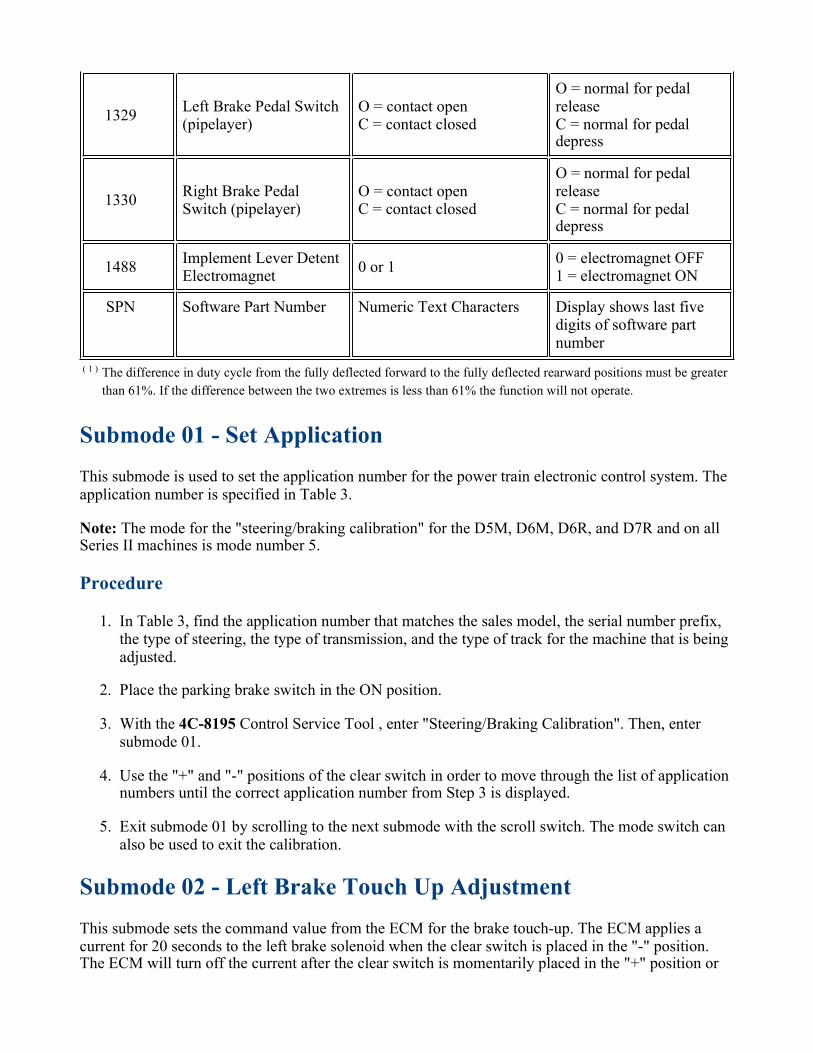
1329Left Brake Pedal Switch(pipelayer)
O = contact openC = contact closed
O = normal for pedalreleaseC = normal for pedaldepress
1330Right Brake PedalSwitch (pipelayer)
O = contact openC = contact closed
O = normal for pedalreleaseC = normal for pedaldepress
1488Implement Lever DetentElectromagnet
0 or 10 = electromagnet OFF1 = electromagnet ON
SPN Software Part Number Numeric Text Characters Display shows last fivedigits of software partnumber
( 1 ) The difference in duty cycle from the fully deflected forward to the fully deflected rearward positions must be greater
than 61%. If the difference between the two extremes is less than 61% the function will not operate.
Submode 01 - Set Application
This submode is used to set the application number for the power train electronic control system. Theapplication number is specified in Table 3.
Note: The mode for the "steering/braking calibration" for the D5M, D6M, D6R, and D7R and on allSeries II machines is mode number 5.
Procedure
In Table 3, find the application number that matches the sales model, the serial number prefix,the type of steering, the type of transmission, and the type of track for the machine that is beingadjusted.
1.
Place the parking brake switch in the ON position.2.
With the 4C-8195 Control Service Tool , enter "Steering/Braking Calibration". Then, entersubmode 01.
3.
Use the "+" and "-" positions of the clear switch in order to move through the list of applicationnumbers until the correct application number from Step 3 is displayed.
4.
Exit submode 01 by scrolling to the next submode with the scroll switch. The mode switch canalso be used to exit the calibration.
5.
Submode 02 - Left Brake Touch Up Adjustment
This submode sets the command value from the ECM for the brake touch-up. The ECM applies acurrent for 20 seconds to the left brake solenoid when the clear switch is placed in the "-" position.The ECM will turn off the current after the clear switch is momentarily placed in the "+" position or

after the current has been applied for 20 seconds. Observe the track speed while the current is beingapplied in order to complete the adjustment of the brake.
Note: This calibration provides smooth brake engagement. Many conditions can affect thiscalibration. Some conditions that can affect the calibration are power train oil temperature and tracktension. If the calibration procedures for submode 2 and for submode 3 are performed and there isharsh engagement of the brakes, readjust the values that were set in the calibration procedure.
Left Brake Adjustment Procedure For Power Shift Torque Converter (PSTC)Transmission
Warm up the power train oil to a minimum of 60 °C (140 °F). Lift the tractor off the ground.Jack stands may be used or the blade and the ripper may be used.
1.
Note: The procedure can be performed with the track on the ground. If these procedures areperformed with the machine on the ground, the ground surface should be hard and level.
Release the parking brake. Set the engine speed to low idle for the D6R Series II, D7R Series II,572R Series II and D8R Series II. Set the engine speed to 910 rpm for the D5M, D6M, D6R,and D7R.
2.
With the 4C-8195 Control Service Tool , enter the steering/braking calibration mode. Entersubmode 02.
3.
Shift the transmission to third gear forward and allow the tracks to rotate for severalrevolutions.
4.
Begin the test. Press the clear switch to the DECREMENT (-) position and then release theswitch. The test current will be applied to the left brake solenoid for 20 seconds.
5.
Observe the left track in order to determine if the left track stops. Wait for 20 seconds in orderto determine if the track stops. Do not press the clear switch more than one time during thesame test. The test current is removed automatically after 20 seconds. The track speed willreturn to normal speed. The track can also be returned to normal speed by pressing and thenreleasing the clear switch to the INCREMENT (+) position.
6.
If the left track stops before returning to normal speed, the preset value must be increasedto 5 units higher. The present value is shown on the display. This creates a new startingpoint. Press and release the clear switch to the INCREMENT (+) position until the valueis changed. Proceed to 5 and repeat the test.
◦
If the left track DOES NOT STOP before returning to normal speed, proceed to Test Step7.
◦
Decrease the present value that is showing on the display to 1 unit lower. Press and release theclear switch to the DECREMENT (-) position until the value is changed. The 20 second testwill begin again. Observe the left track in order to determine if the track stops. Wait for 20seconds for the track to stop.
7.
If the left track stops at any time before returning to normal speed, calibration of the leftbrake is complete. Exit submode 02 by scrolling to the next submode. Use the scrollswitch or use the mode switch also to exit the calibration.
◦

If the left track does not stop before returning to normal speed, exit this procedure andperform this procedure again.
◦
Left Brake Adjustment Procedure For Direct Drive Power Shift Transmission(DDPS)
Note: This procedure is not for R Series II machines. For R Series II machines, proceed to the bottomof this procedure.
The following procedure requires monitoring engine speed. Engine speed can be monitored by usingthe status screens in the Cat ET service tool or by using an external tachometer. If the ability tomonitor engine speed is not available, use the "Alternate Left Brake Adjustment Procedure For DirectDrive Power Shift Transmission (DDPS)".
Warm up the power train oil to a minimum of 60 °C (140 °F). Lift the tractor off the ground.Jack stands can be used or the blade and the ripper can be used.
1.
Note: The procedure can be performed with the track on the ground. If these procedures areperformed with the machine on the ground, the ground surface should be hard. The groundsurface should also be level.
Release the parking brake. Set the engine speed to 910 ± 5 rpm.2.
Shift the transmission to third gear forward and allow the tracks to rotate for at least threeseconds. After three seconds, record the average engine speed as engine speed A.
3.
Calculate engine speed B with the following formulas:4.
D5M - engine speed B rpm = engine speed A rpm - 27 rpm
D6R - engine speed B rpm = engine speed A rpm - 115 rpm
With the 4C-8195 Control Service Tool , enter the steering/braking calibration mode. Then,enter submode 02.
5.
Shift the transmission to third gear forward and allow the tracks to rotate for severalrevolutions.
6.
Press the clear switch to the DECREMENT (-) position and then release the switch. The testcurrent will be applied to the left brake solenoid for 20 seconds.
7.
Wait at least three seconds from the start of the test. Observe engine speed in order to determineif the speed drops below engine speed B. Wait for 20 seconds so that the engine speed canstabilize. Do not press the clear switch more than one time during the same test. After 20seconds, the test current is automatically removed and engine speed and track speed will returnto normal speed. The engine and the track can also be returned to normal speed by pressing theclear switch to the INCREMENT (+) position and then releasing the switch.
8.
If the speed of the engine drops below engine speed B and the engine has not returned tonormal speed, increase the present value that is shown on the display to 5 units higher.Press and release the clear switch to the INCREMENT (+) position until the value haschanged. Return to Step 5 in order to repeat the test.
◦

If the speed of the engine does not drop below engine speed B and the engine hasreturned to normal speed, proceed to Test Step 9.
◦
Decrease the present value that is shown on the display to 1 unit lower. Press and release theclear switch to the DECREMENT (-) position until the value has changed. The 20 second testwill begin again. Wait at least three seconds. Observe the engine speed to determine if the speeddrops below engine speed B. Wait for 20 seconds so that the engine speed can stabilize.
9.
If the speed of the engine drops below engine speed B and the engine has not returned tonormal speed, the calibration of the left brake touch up is complete. Exit submode 02 byscrolling to the next submode with the scroll switch. The mode switch can also be used toexit the calibration.
◦
If the speed of the engine does not drop below engine speed B and the engine hasreturned to normal speed, exit this procedure and perform this procedure again.
◦
Left Brake Adjustment Procedure For Direct Drive Power Shift Transmission(DDPS) On R Series II Machines
The following procedure requires monitoring engine fuel position. Engine fuel position can bemonitored using the status screens (engine) in the Cat ET service tool or the left brake adjustmentprocedure should be performed using the Cat ET service tool. If the ability to monitor engine fuelposition is not available, use the alternate left brake adjustment procedure for direct drive power shifttransmission (DDPS).
Warm up the power train oil a minimum of 60 °C (140 °F). Lift the tractor off the ground. Jackstands can be used or the blade and the ripper can be used.
1.
Note: The procedure can be performed with the track on the ground. If these procedures areperformed with the machine on the ground, the ground surface should be hard and level.
Release the parking brake.2.
Set the engine speed to low idle (800 rpm).3.
Shift the transmission to third gear forward and allow the tracks to rotate for at least threeseconds. After 3 seconds, record the average engine fuel position as fuel position A.
4.
Calculate engine fuel position "B" with the following formula: D6R, Series II - engine fuelposition B = engine fuel position A + 15
5.
With the 4C-8195 Control Service Tool, enter the steering/braking calibration mode. Then entersubmode 02.
6.
Shift the transmission to third gear forward and allow the tracks to rotate for severalrevolutions.
7.
Press the clear switch to the DECREMENT (-) position and then release the switch. The testcurrent will be applied to the left brake solenoid for 20 seconds.
8.
Wait at least three seconds from the start of the test. Observe engine fuel position in order todetermine if the engine fuel position increases above engine fuel position B. Wait for 20
9.

seconds so that the engine fuel position can stabilize. Do not press the clear switch more thanone time during the same test. After 20 seconds, the test current is automatically removed. Theleft brake adjustment test current can also be returned to normal by pressing the clear switch tothe INCREMENT (+) position and then releasing the switch.
Note: If the engine fuel position increases above engine fuel position B and the engine fuelposition has not returned to normal, increase the present value that is shown on the display to 5units higher. Press and release the clear switch to the INCREMENT (+) position until the valuehas changed. Return to Step 5 in order to repeat the test. If the engine fuel position does notincrease above engine fuel position B and the engine fuel position has returned to normal,proceed to Test Step 10.
Decrease the present value that is shown on the display to 1 unit lower. Press and released theclear switch to the DECREMENT (-) position until the value has changed. The 20 seconds testwill begin again. Wait at least three seconds. Observe the engine fuel position to determine ifthe engine fuel position increases above engine fuel position B. Wait for 20 seconds so that theengine fuel position can stabilize.
10.
Note: If the engine fuel position increases above the engine fuel position B and the engine fuelposition has not returned to normal, the calibration of the left brake touch up is complete. Exitsubmode 02 by scrolling to the next submode with the scroll switch. The mode switch can alsobe used to exit the calibration. If the engine fuel position does not increase above the enginefuel position B and the engine fuel position has returned to normal, repeat Step 9.
Alternate Left Brake Adjustment Procedure For Direct Drive Power ShiftTransmission (DDPS)
Note: This procedure is not for R Series II machines. For R Series II machines, proceed to the bottomof this procedure.
Warm up the power train oil to a minimum of 60 °C (140 °F). Lift the tractor off the ground.Jack stands can be used or the blade and the ripper can be used.
1.
Note: The procedure can be performed with the track on the ground. If this procedure isperformed with the machine on the ground, the ground surface should be hard. The groundsurface should also be level.
Release the parking brake. Set the engine speed to 910 ± 5 rpm.2.
With the 4C-8195 Control Service Tool , enter the steering/braking calibration mode. Then,enter submode 02.
3.
Shift the transmission to third gear forward and allow the tracks to rotate for severalrevolutions.
4.
Press the clear switch to the DECREMENT (-) position and then release the switch. The testcurrent will be applied to the left brake solenoid for 20 seconds.
5.
Observe the left track for a visible decrease in track speed. Wait for 20 seconds so that the trackspeed can decrease. Do not press the clear switch more than one time during the same test.After 20 seconds, the test current is automatically removed and track speed will return to
6.

normal speed. The track can also be returned to normal speed by pressing the clear switch to theINCREMENT (+) position and then releasing the switch.
If the speed of the left track decreases at any time before returning to normal speed,increase the present value that is shown on the display to 5 units higher. Press and releasethe clear switch to the INCREMENT (+) position until the value has changed. Return toStep 5 in order to repeat the test.
◦
If the speed of the left track does not decrease before returning to normal speed, proceedto 7.
◦
Decrease the present value that is shown on the display to 1 unit lower. Press and release theclear switch to the DECREMENT (-) position until the value has changed. The 20 second testwill begin again. Observe the left track for a visible decrease in track speed. Wait for 20seconds so that the speed can decrease.
7.
If the speed of the left track decreases at any time before returning to normal speed,calibration of the left brake is complete. Exit submode 02 by scrolling to the nextsubmode with the scroll switch. The mode switch can also be used to exit the calibration.
◦
If the speed of the left track does not decrease before returning to normal speed, repeatStep 7.
◦
Alternate Left Brake Adjustment Procedure For Direct Drive Power ShiftTransmission (DDPS) On R Series II Machines
Warm up the power train oil a minimum of 60 °C (140 °F). Lift the tractor off the ground. Jackstands can be used or the blade and the ripper can be used.
1.
Note: The procedure can be performed with the track on the ground. If these procedures areperformed with the machine on the ground, the ground surface should be hard and level.
Release the parking brake. Set the engine speed to low idle (800 rpm).2.
Shift the transmission to third gear forward and allow the tracks to rotate for at least threeseconds. After three seconds, record the average engine speed as engine speed A.
3.
Calculate engine speed B with the following formula: D6R Series II - engine speed B = enginespeed A - 25 rpm.
4.
With the 4C-8195 Control Service Tool, enter the steering/braking calibration mode.5.
Enter submode 026.
Shift the transmission to third gear forward and allow the tracks to rotate for severalrevolutions.
7.
Press the clear switch to the DECREMENT (-) position and then release the switch. The testcurrent will be applied to the left brake solenoid for 20 seconds.
8.
Observe the engine speed for a visible decrease in track speed. The decrease in track speed willlast one to two seconds before returning to normal speed. Do not press the clear switch more
9.

than one time during the same test. After 20 seconds, the test current is automatically removed.The left brake adjustment test current can also be returned to normal by pressing the clearswitch to the INCREMENT (+) position and then releasing the switch.
Note: If the engine speed drops below engine speed B at any time before returning to normalspeed, increase the present value that is shown on the display to 5 units higher. Press andrelease the clear switch to INCREMENT (+) position until the value has changed. Return toStep 5 in order to repeat the test. If the engine speed does not drop below engine speed B at anytime before returning to normal speed, proceed to Step 9
Decrease the present value that is shown on the display to 1 unit lower. Press and release theclear switch to the DECREMENT (-) position until the value has changed. The 20 second testwill begin again. Observe the engine speed to determine if the engine speed drops below enginespeed B at any time.
10.
Note: If the engine speed drops below engine speed B at any time before returning to normalspeed, the calibration of the left brake touch up is complete. Exit submode 02 by scrolling to thenext submode with the scroll switch. The mode switch can also be used to exit the calibration.If the engine speed does not drop below engine speed B at any time before returning to normalspeed, repeat Step 9.
Submode 03 - Right Brake Touch Up Adjustment
This submode sets the command value for a smooth brake touch up. The ECM applies a test currentfor 20 seconds to the right brake solenoid when the clear switch is placed in the DECREMENT (-)position. The ECM will turn off the test current when the clear switch is placed in the INCREMENT(+) position or when the test current has been applied for 20 seconds. The brake adjustment isperformed by observing the effect of the test current on the speed of the track.
Note: This calibration provides smooth brake engagement. Many conditions can affect thiscalibration. Some conditions that can affect the calibration are power train oil temperature and tracktension. If the calibration procedures for submode 2 and for submode 3 are performed and there isharsh engagement of the brakes, readjust the values that were set in the calibration procedure.
Right Brake Adjustment Procedure For Power Shift Torque Converter (PSTC)Transmission
Warm up the power train oil to a minimum of 60 °C (140 °F). Lift the tractor off the ground.Jack stands can be used or the blade and the ripper can be used.
1.
Note: The procedure can be performed with the track on the ground. If these procedures areperformed with the machine on the ground, the ground surface should be hard and level.
Release the parking brake. Set the engine speed to low idle for the D6R Series II, D7R Series II,and D8R Series II. Set the engine speed to 910 rpm for the D5M, D6M, D6R, and D7R.
2.
With the 4C-8195 Control Service Tool , enter the steering/braking calibration mode. Then,enter submode 03.
3.
Shift the transmission to third gear forward and allow the tracks to rotate for severalrevolutions.
4.
Begin the test by pressing the clear switch to the DECREMENT (-) position and then releasethe switch. The test current will be applied to the right brake solenoid for 20 seconds.
5.
Observe the right track in order to determine if the track stops. Wait for 20 seconds for the trackto stop. Do not press the clear switch more than one time during the same test. After 20seconds, the test current is automatically removed and the track speed will return to normalspeed. The track can also be returned to normal speed by pressing the clear switch to theINCREMENT (+) position and then releasing the switch.
6.
If the right track stops at any time before returning to normal speed, increase the presentvalue to 5 units higher. The value is shown on the display. Press and release the clearswitch to the INCREMENT (+) position until the value is changed. Return to 5 and repeatthe test.
◦
If the right track does not stop before returning to normal speed, proceed to the next step. ◦
Decrease the present value that is shown on the display to 1 unit lower. Press and release theclear switch to the DECREMENT (-) position until the value is changed. The 20 second testwill begin again. Observe the right track in order to determine if the track stops. Wait for 20seconds for the track to stop.
7.
If the right track stops at any time before returning to normal speed, calibration of theright brake is complete. Exit submode 03 by scrolling to the next submode. The scrollswitch and the mode switch can also be used to exit the calibration.
◦
If the right track does not stop before returning to normal speed, return to 7.◦
Right Brake Adjustment Procedure For Direct Drive Power Shift Transmission(DDPS)
Note: This procedure is not for R Series II machines. For R Series II machines, proceed to the bottomof this procedure.
The following procedure requires monitoring engine speed. Engine speed can be monitored by usingthe status screens in the Cat ET service tool or by using an external tachometer. If the ability tomonitor engine speed is not available, use the "Alternate Right Brake Adjustment Procedure ForDirect Drive Power Shift Transmission (DDPS)".
Warm up the power train oil to a minimum of 60 °C (140 °F). Lift the tractor off the ground.Jack stands can be used or the blade and the ripper can be used.
1.
Note: The procedure can be performed with the track on the ground. If these procedures areperformed with the machine on the ground, the ground surface should be hard. The groundsurface should also be level.
Release the parking brake. Set the engine speed to 910 ± 5 rpm.2.
Shift the transmission to third gear forward and allow the tracks to rotate for at least threeseconds. After three seconds, record the average engine speed as engine speed "A".
3.
Calculate engine speed B with the following formulas:4.
D5M - engine speed B rpm = engine speed A rpm - 27 rpm
D6R - engine speed B rpm = engine speed A rpm - 115 rpm
With the 4C-8195 Control Service Tool , enter steering/braking calibration mode. Then, entersubmode 03.
5.
Shift the transmission to third gear forward and allow the tracks to rotate for severalrevolutions.
6.
Press the clear switch to the DECREMENT (-) position and then release the switch. The testcurrent will be applied to the right brake solenoid for 20 seconds.
7.
Wait at least three seconds from the start of the test. Observe engine speed in order to determineif the speed drops below engine speed B. Wait for 20 seconds so that the engine speed canstabilize. Do not press the clear switch more than one time during the same test. After 20seconds, the test current is automatically removed and engine speed and track speed will returnto normal speed. The engine and the track can also be returned to normal speed by pressing theclear switch to the INCREMENT (+) position and then releasing the switch.
8.
If the speed of the engine drops below engine speed "B" and the engine has not returnedto normal speed, increase the present value that is shown on the display to 5 units higher.Press and release the clear switch to the INCREMENT (+) position until the value haschanged. Return to Step 5 in order to repeat the test.
◦
If the speed of the engine does not drop below engine speed B and the engine hasreturned to normal speed, proceed to 9.
◦
Decrease the present value that is shown on the display to 1 unit lower. Press and release theclear switch to the DECREMENT (-) position until the value has changed. The 20 second testwill begin again. Wait at least three seconds. Observe the engine speed to determine if the speeddrops below engine speed B. Wait for 20 seconds so that the engine speed can stabilize.
9.
If the speed of the engine drops below engine speed B and the engine has not returned tonormal speed, the calibration of the right brake touch up is complete. Exit submode 03 byscrolling to the next submode with the scroll switch. The mode switch can also be used toexit the calibration.
◦
If the speed of the engine does not drop below engine speed B and the engine hasreturned to normal speed, Repeat Step 9.
◦
Right Brake Adjustment Procedure For Direct Drive Power Shift Transmission(DDPS) On R Series II Machines
The following procedure requires monitoring engine fuel position. Engine fuel position can bemonitored using the status screens (engine) in the Caterpillar Electronic Technician (ET) service toolor the right brake adjustment procedure should be performed using the Cat ET service tool. If theability to monitor engine fuel position is not available, use the Alternate Right Brake AdjustmentProcedure For Direct Drive Power Shift Transmission (DDPS).
Warm up the power train oil a minimum of 60 °C (140 °F). Lift the tractor off the ground. Jackstands can be used or the blade and the ripper can be used.
1.

Note: The procedure can be performed with the track on the ground. If these procedures areperformed with the machine on the ground, the ground surface should be hard. The groundsurface should also be level.
Release the parking brake. Set the engine speed to low idle (800 rpm).2.
Shift the transmission to third gear forward and allow the tracks to rotate for at least threeseconds. After 3 seconds, record the average engine fuel position as fuel position A.
3.
Calculate engine fuel position B with the following formula: D6R, Series II - engine fuelposition B = engine fuel position A + 15
4.
With the 4C-8195 Control Service Tool, enter the steering/braking calibration mode. Then entersubmode 03.
5.
Shift the transmission to third gear forward and allow the tracks to rotate for severalrevolutions.
6.
Press the clear switch to the DECREMENT (-) position and then release the switch. The testcurrent will be applied to the right brake solenoid for 20 seconds.
7.
Wait at least three seconds from the start of the test. Observe engine fuel position in order todetermine if the engine fuel position increases above engine fuel position B. Wait for 20seconds so that the engine fuel position can stabilize. Do not press the clear switch more thanone time during the same test. After 20 seconds, the test current is automatically removed. Theright brake adjustment test current can also be returned to normal by pressing the clear switch tothe INCREMENT position (+) and then releasing the switch.
8.
If the engine fuel position increases above engine fuel position B and the engine fuelposition has not returned to normal, increase the present value that is shown on thedisplay to 5 units higher. Press and release the clear switch to the INCREMENT position(+) until the value has changed. Return to Step 5 in order to repeat the test.
◦
If the engine fuel position does not increase above engine fuel position B and the enginefuel position has returned to normal, proceed to Step 9.
◦
Decrease the present value that is shown on the display to 1 unit lower. Press and released theclear switch to the DECREMENT (-) position until the value has changed. The 20 seconds testwill begin again. Wait at least three seconds. Observe the engine fuel position to determine ifthe engine fuel position increases above engine fuel position B. Wait for 20 seconds so that theengine fuel position can stabilize.
9.
If the engine fuel position increases above the engine fuel position B and the engine fuelposition has not returned to normal, the calibration of the right brake touch up iscomplete. Exit submode 02 by scrolling to the next submode with the scroll switch. Themode switch can also be used to exit the calibration.
◦
If the engine fuel position does not increase above the engine fuel position B and theengine fuel position has returned to normal, repeat Step 9.
◦
Alternate Right Brake Adjustment Procedure For Direct Drive Power ShiftTransmission (DDPS)
Note: This procedure is NOT for R Series II machines. For R Series II machines, proceed to thebottom of this procedure.
Warm up the power train oil to a minimum of 60 °C (140 °F). Lift the tractor off the ground.Jack stands can be used or the blade and the ripper can be used.
1.
Note: The procedure can be performed with the track on the ground. If this procedure isperformed with the machine on the ground, the ground surface should be hard. The groundsurface should also be level.
Release the parking brake. Set the engine speed to 910 ± 5 rpm.2.
With the 4C-8195 Control Service Tool , enter "Steering/Braking Calibration Mode". Then,enter submode 03.
3.
Shift the transmission to third gear forward and allow the tracks to rotate for severalrevolutions.
4.
Press the clear switch to the DECREMENT (-) position and then release the switch. The testcurrent will be applied to the right brake solenoid for 20 seconds.
5.
Observe the right track for a visible decrease in track speed. Wait for 20 seconds so that thetrack speed can decrease. DO NOT press the clear switch more than one time during the sametest. After 20 seconds, the test current is automatically removed and track speed will return tonormal speed. The track can also be returned to normal speed by pressing the clear switch to theINCREMENT (+) position and then releasing the switch.
6.
If the speed of the right track decreases at any time before returning to normal speed,increase the present value that is shown on the display to 5 units higher. Press and releasethe clear switch to the INCREMENT (+) until the value has changed. Return to Step 5 inorder to repeat the test.
◦
If the speed of the right track does not decrease before returning to normal speed, proceedto 7.
◦
Decrease the present value that is shown on the display to 1 unit lower. Press and release theclear switch to the DECREMENT (-) position until the value has changed. The 20 second testwill begin again. Observe the right track for a visible decrease in track speed. Wait for 20seconds so that the speed can decrease.
7.
If the speed of the right track decreases at any time before returning to normal speed,calibration of the right brake is complete. Exit submode 03 by scrolling to the nextsubmode with the scroll switch. The mode switch can also be used to exit the calibration.
◦
If the speed of the right track does not decrease before returning to normal speed, repeatStep 7.
◦
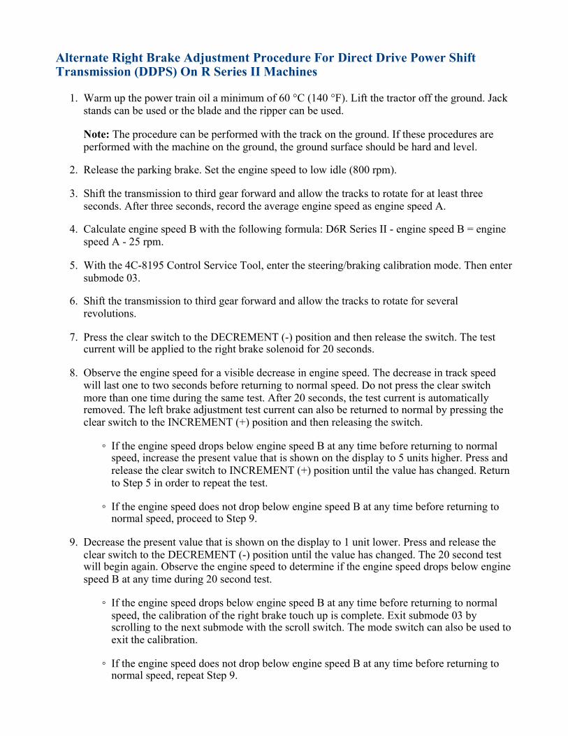
Alternate Right Brake Adjustment Procedure For Direct Drive Power ShiftTransmission (DDPS) On R Series II Machines
Warm up the power train oil a minimum of 60 °C (140 °F). Lift the tractor off the ground. Jackstands can be used or the blade and the ripper can be used.
1.
Note: The procedure can be performed with the track on the ground. If these procedures areperformed with the machine on the ground, the ground surface should be hard and level.
Release the parking brake. Set the engine speed to low idle (800 rpm).2.
Shift the transmission to third gear forward and allow the tracks to rotate for at least threeseconds. After three seconds, record the average engine speed as engine speed A.
3.
Calculate engine speed B with the following formula: D6R Series II - engine speed B = enginespeed A - 25 rpm.
4.
With the 4C-8195 Control Service Tool, enter the steering/braking calibration mode. Then entersubmode 03.
5.
Shift the transmission to third gear forward and allow the tracks to rotate for severalrevolutions.
6.
Press the clear switch to the DECREMENT (-) position and then release the switch. The testcurrent will be applied to the right brake solenoid for 20 seconds.
7.
Observe the engine speed for a visible decrease in engine speed. The decrease in track speedwill last one to two seconds before returning to normal speed. Do not press the clear switchmore than one time during the same test. After 20 seconds, the test current is automaticallyremoved. The left brake adjustment test current can also be returned to normal by pressing theclear switch to the INCREMENT (+) position and then releasing the switch.
8.
If the engine speed drops below engine speed B at any time before returning to normalspeed, increase the present value that is shown on the display to 5 units higher. Press andrelease the clear switch to INCREMENT (+) position until the value has changed. Returnto Step 5 in order to repeat the test.
◦
If the engine speed does not drop below engine speed B at any time before returning tonormal speed, proceed to Step 9.
◦
Decrease the present value that is shown on the display to 1 unit lower. Press and release theclear switch to the DECREMENT (-) position until the value has changed. The 20 second testwill begin again. Observe the engine speed to determine if the engine speed drops below enginespeed B at any time during 20 second test.
9.
If the engine speed drops below engine speed B at any time before returning to normalspeed, the calibration of the right brake touch up is complete. Exit submode 03 byscrolling to the next submode with the scroll switch. The mode switch can also be used toexit the calibration.
◦
If the engine speed does not drop below engine speed B at any time before returning tonormal speed, repeat Step 9.
◦
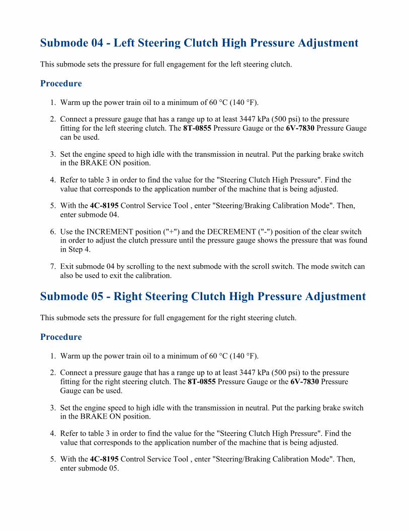
Submode 04 - Left Steering Clutch High Pressure Adjustment
This submode sets the pressure for full engagement for the left steering clutch.
Procedure
Warm up the power train oil to a minimum of 60 °C (140 °F).1.
Connect a pressure gauge that has a range up to at least 3447 kPa (500 psi) to the pressurefitting for the left steering clutch. The 8T-0855 Pressure Gauge or the 6V-7830 Pressure Gaugecan be used.
2.
Set the engine speed to high idle with the transmission in neutral. Put the parking brake switchin the BRAKE ON position.
3.
Refer to table 3 in order to find the value for the "Steering Clutch High Pressure". Find thevalue that corresponds to the application number of the machine that is being adjusted.
4.
With the 4C-8195 Control Service Tool , enter "Steering/Braking Calibration Mode". Then,enter submode 04.
5.
Use the INCREMENT position ("+") and the DECREMENT ("-") position of the clear switchin order to adjust the clutch pressure until the pressure gauge shows the pressure that was foundin Step 4.
6.
Exit submode 04 by scrolling to the next submode with the scroll switch. The mode switch canalso be used to exit the calibration.
7.
Submode 05 - Right Steering Clutch High Pressure Adjustment
This submode sets the pressure for full engagement for the right steering clutch.
Procedure
Warm up the power train oil to a minimum of 60 °C (140 °F).1.
Connect a pressure gauge that has a range up to at least 3447 kPa (500 psi) to the pressurefitting for the right steering clutch. The 8T-0855 Pressure Gauge or the 6V-7830 PressureGauge can be used.
2.
Set the engine speed to high idle with the transmission in neutral. Put the parking brake switchin the BRAKE ON position.
3.
Refer to table 3 in order to find the value for the "Steering Clutch High Pressure". Find thevalue that corresponds to the application number of the machine that is being adjusted.
4.
With the 4C-8195 Control Service Tool , enter "Steering/Braking Calibration Mode". Then,enter submode 05.
5.

Use the INCREMENT (+) and the DECREMENT (-) positions of the clear switch to adjust theclutch pressure until the pressure gauge shows the pressure that was found in Step 4.
6.
Exit submode 05 by scrolling to the next submode with the scroll switch. The mode switch canalso be used to exit the calibration.
7.
Submode 06 - Left Brake Low Pressure Adjustment
This submode sets the lowest range of pressure for the left brake.
Procedure
Warm up the power train oil to a minimum of 60 °C (140 °F).1.
Connect a pressure gauge that has a range that is no greater than 483 kPa (70 psi). Connect thegauge in line with a valve to the pressure fitting for the left brake. The valve should be closed.The 8T-0853 Pressure Gauge or the 6V-7830 Pressure Gauge can be used.
2.
NOTICE
Use of the 6V-7830 Pressure Gauge is highly recommended. It does notneed a valve in line for protection. However, if a standard low pressuregauge such as 8T-0853 Pressure Gauge is used, a valve must be used in
line with the gauge to protect the gauge from high pressure whilechanging submodes. If a valve is not used for the standard gauge, thegauge may become permanently damaged while changing submodes.
Set the engine speed to high idle with the transmission in neutral. Put the parking brake switchin the BRAKE OFF position.
3.
Refer to table 3 in order to find the value for the "Brake Low Pressure". Find the value thatcorresponds to the application number of the machine that is being adjusted.
4.
With the 4C-8195 Control Service Tool , enter "Steering/Braking Calibration Mode". Then,enter submode 06.
5.
Open the valve. Use the INCREMENT (+) position and the DECREMENT (-) position of theclear switch to adjust the brake pressure until the pressure gauge shows the pressure that wasfound in Step 4.
6.
Note: The value in table 3 for the "brake low pressure" may not be attainable. This is due tovarious conditions. Some of the conditions are no low pressure gauge, gauge hysteresis, andcold power train oil. Bring the pressures as close as possible to the specified value. Theadjustments for low brake pressure do not need to be exactly on the mark.

Close the valve or disconnect the gauge before submode 06 is exited. Exit submode 06 byscrolling to the next submode with the scroll switch. The mode switch can also be used to exitthe calibration.
7.
Submode 07 - Right Brake Low Pressure Adjustment
This submode sets the lowest range of pressure for the right brake.
Procedure
Warm up the power train oil to a minimum of 60 °C (140 °F).1.
Connect a pressure gauge that has a range that is no greater than 483 kPa (70 psi). Connect thegauge in line with a valve to the pressure fitting for the right brake. The valve should be closed.The 8T-0853 Pressure Gauge or the 6V-7830 Pressure Gauge can be used.
2.
NOTICE
Use of the 6V-7830 Pressure Gauge is highly recommended. It does notneed a valve in line for protection. However, if a standard low pressuregauge such as 8T-0853 Pressure Gauge is used, a valve must be used in
line with the gauge to protect the gauge from high pressure whilechanging submodes. If a valve is not used for the standard gauge, thegauge may become permanently damaged while changing submodes.
Set the engine speed to high idle with the transmission in neutral. Put the parking brake switchin the BRAKE OFF position.
3.
Refer to table 3 in order to find the value for the brake low pressure. Find the value thatcorresponds to the application number of the machine that is being adjusted.
4.
With the 4C-8195 Control Service Tool , enter "Steering/Braking Calibration Mode ". Then,enter submode 07.
5.
Open the valve. Use the INCREMENT (+) position and the DECREMENT (-) position of theclear switch to adjust the brake pressure to the pressure that was found in Step 4.
6.
Note: The value in table3 for the brake low pressure may not be attainable. This is due tovarious conditions. Some of the conditions are no low pressure gauge, gauge hysteresis, andcold power train oil. Bring the pressures as close as possible to the specified value. Theadjustments for low brake pressure do not need to be exactly on the mark.
Close the valve or disconnect the gauge before submode 07 is exited. Exit submode 07 byscrolling to the next submode with the scroll switch. The mode switch can also be used to exitthe calibration.
7.

Submode 08 - Left Steering Clutch Low Pressure Adjustment
This submode sets the lowest pressure range for the left steering clutch.
Procedure
Warm up the power train oil to a minimum of 60 °C (140 °F).1.
Connect a pressure gauge that has a range that is no greater than 483 kPa (70 psi). Connect thegauge in line with a valve to the pressure fitting for the left steering clutch. The valve should beclosed. The 8T-0853 Pressure Gauge or the 6V-7830 Pressure Gauge can be used.
2.
NOTICE
Use of the 6V-7830 Pressure Gauge is highly recommended. It does notneed a valve in line for protection. However, if a standard low pressuregauge such as 8T-0853 Pressure Gauge is used, a valve must be used in
line with the gauge to protect the gauge from high pressure whilechanging submodes. If a valve is not used for the standard gauge, thegauge may become permanently damaged while changing submodes.
Set the engine speed to high idle with the transmission in neutral. Put the parking brake switchin the "BRAKE ON" position.
3.
Refer to Table 3 in order to find the value for the steering clutch low pressure. Find the valuethat corresponds to the application number of the machine that is being adjusted.
4.
With the 4C-8195 Control Service Tool , enter steering/braking calibration mode. Then, entersubmode 08.
5.
Open the valve. Use the INCREMENT (+) position and the DECREMENT (-) position of theclear switch to adjust the clutch pressure to the pressure that was found in Step 4.
6.
Note: The value in Table 3 for the "steering clutch low pressure" may not be attainable. This isdue to various conditions. Some of the conditions are no low pressure gauge, gauge hysteresis,and cold power train oil. Bring the pressures as close as possible to the specified value. Theadjustments for "steering clutch low pressure" do not need to be exactly on the mark.
Close the valve or disconnect the gauge before submode 08 is exited. Exit submode 08 byscrolling to the next submode with the scroll switch. The mode switch can also be used to exitthe calibration.
7.
Submode 09 - Right Steering Clutch Low Pressure Adjustment
This submode sets the lowest pressure range for the right steering clutch.

Procedure
Warm up the power train oil to a minimum of 60 °C (140 °F).1.
Connect a pressure gauge that has a range that is no greater than 483 kPa (70 psi). Connect thegauge in line with a valve to the pressure fitting for the right steering clutch. The valve shouldbe closed. The 8T-0853 Pressure Gauge or the 6V-7830 Pressure Gauge can be used.
2.
NOTICE
Use of the 6V-7830 Pressure Gauge is highly recommended. It does notneed a valve in line for protection. However, if a standard low pressuregauge such as 8T-0853 Pressure Gauge is used, a valve must be used in
line with the gauge to protect the gauge from high pressure whilechanging submodes. If a valve is not used for the standard gauge, thegauge may become permanently damaged while changing submodes.
Set the engine speed to high idle with the transmission in neutral. Put the parking brake switchin the BRAKE ON position.
3.
Refer to Table 3 in order to find the value for the steering clutch low pressure. Find the valuethat corresponds to the application number of the machine that is being adjusted.
4.
With the 4C-8195 Control Service Tool , enter steering/braking calibration mode. Then, entersubmode 09.
5.
Open the valve. Use the INCREMENT (+) position and the DECREMENT (-) position of theclear switch to adjust the clutch pressure to the pressure that was found in Step 4.
6.
Note: The value in Table 3 for the "steering clutch low pressure" may not be attainable. This isdue to various conditions. Some of the conditions are no low pressure gauge, gauge hysteresis,and cold power train oil. Bring the pressures as close as possible to the specified value. Theadjustments for steering clutch low pressure do not need to be exactly on the mark.
Close the valve or disconnect the gauge before submode 09 is exited.. Exit submode 09 byscrolling to the next submode with the scroll switch. The mode switch can also be used to exitthe calibration.
7.
Submode 10 And 11 - Inching Pedal Released Position AndInching Pedal Depressed Position
These procedures calibrate the released position and the depressed position of the inching pedal.Always perform the calibrations for both the released position and the depressed position.

Illustration 3 g00597744
Display Area
(1) Submode identifier. (2) Accept status identifier.
Illustration 4 g00597745
Symbols that are shown on the accept status identifier
(3) Accepted Symbol. (4) Accepted symbol. (5) Not accepted symbol. (6) Not accepted symbol.
With the 4C-8195 Control Service Tool , enter steering/braking calibration mode. Then, entersubmode 10.
1.
Depress the inching pedal completely. Release the inching pedal slowly.2.
While the inching pedal is released, press the clear switch to the DECREMENT (-) position inorder to store the calibration value for the released position. While the switch is pressed, theaccept status identifier (2) will briefly show the accepted symbol (4) or the not accepted symbol(6) . Observe the accept status identifier (2) when the switch is pressed.
3.
Expected Result: The accepted symbol (4) or the not accepted symbol (6) shows on the acceptstatus identifier.
Results:
The accepted symbol (4) was showing. Proceed to 4. ◦

The not accepted symbol (6) was showing. Check that the inching pedal is completelyreleased. Repeat step 3. If the not accepted symbol (6) is shown or if a CID 0573 FMI 08diagnostic code is present, use the component data display mode in order to check therange of the inching pedal position sensor. The acceptable range is listed in thecomponent data display mode section of this manual. The CID 0573 FMI 08 proceduremay need to be performed.
◦
Press the scroll switch in order to enter submode 11.4.
Depress the inching pedal completely by using normal effort to hold the pedal in the depressedposition. Do not press hard on the pedal. While the pedal is held in the depressed position, pressthe clear switch to the DECREMENT (-) position in order to store the calibration value for theDEPRESSED position. When the switch is depressed, the accept status identifier (2) willbriefly show accepted symbol (4) or not accepted symbol (6) . Observe the accept statusidentifier (2) when the switch is pressed.
5.
Expected Result: The accepted symbol (4) or the not accepted symbol (6) shows on the acceptstatus identifier.
Results:
Accepted symbol "4" was showing. The calibration of the inching pedal is complete. Exitthe inching pedal calibration mode by using the scroll switch. The mode switch can alsobe used to exit the calibration.
◦
Not accepted symbol "6" was showing. Determine if the inching pedal is completelydepressed. Repeat step 5. If not accepted symbol "6" is shown or if a CID 0573 FMI 08diagnostic code is present, use the "Component Data Display Mode" section of thismanual. The CID 0573 FMI 08 procedure may need to be performed.
◦
Submode 12 And 13 - Service Brake Pedal Released PositionAnd Service Brake Pedal Depressed Position
These adjustments modes are used to calibrate the released position and the depressed position of theservice brake pedal. Always perform both released and depressed position calibrations.
Note: This calibration applies to the D5N and D6N only.
The service brake pedal sensor values must be within the following limits to complete the calibrationprocedure. If it is outside of these limits a service brake pedal sensor calibration fault will be activeCID 0468 FMI 13.
Brake pedal released calibration --> sensor duty cycle between 10% and 33%•
Brake pedal depressed calibration --> sensor duty cycle between 40% and 62%•
Brake pedal range --> sensor duty cycle delta between 22% and 36%•
(Change in value between released calibration and depressed calibration)•
If the service brake pedal sensor value is 5.5% duty cycle lower than the calibrated released positionor 5.5% duty cycle higher than the calibrated depressed position, a service brake pedal sensorcalibration fault will be active CID 0468 FMI 13.
The service brake pedal sensor duty cycle must be between 8% and 64% duty cycle. If the sensor isoutside of these limits a service brake pedal sensor out of range fault will be active CID 0468 FMI 08and a service brake pedal sensor calibration fault will be active CID 0468 FMI 13.
If a short circuit to battery diagnostic condition occurs on the secondary brake dump valve circuitbefore the service brake pedal position sensor value has reached (Brake pedal released calibrationvalue + 17%), a secondary brake solenoid short circuit to battery diagnostic will be active CID 0722FMI 03. This may be caused by a secondary brake switch that is closed when the service brake pedalposition sensor indicates that the secondary brake switch should be open.
If a short circuit to battery diagnostic condition does not occur on the secondary brake dump valvecircuit (this is how the ECM reads the status of the service brake pedal switch) before the servicebrake pedal position sensor value has reached.
Note: Brake pedal depressed calibration value - 1%, a Secondary brake switch invalid diagnostic willbe active CID 0298 FMI 02. This may be caused by a secondary brake switch that is open when theservice brake pedal position sensor indicates that the secondary brake switch should be closed. Thisfault will stay active until the service brake pedal switch activation has been detected at the properservice brake pedal position (based on service brake pedal position sensor value
The service brake pedal sensor must calibrate within the proper range of values.•
The service brake pedal sensor must operate within the proper range of values.•
The service brake pedal switch must not close before the sensor reaches the proper range ofvalues.
•
The service brake pedal switch must close before the service brake pedal position exceeds theproper range of values.
•
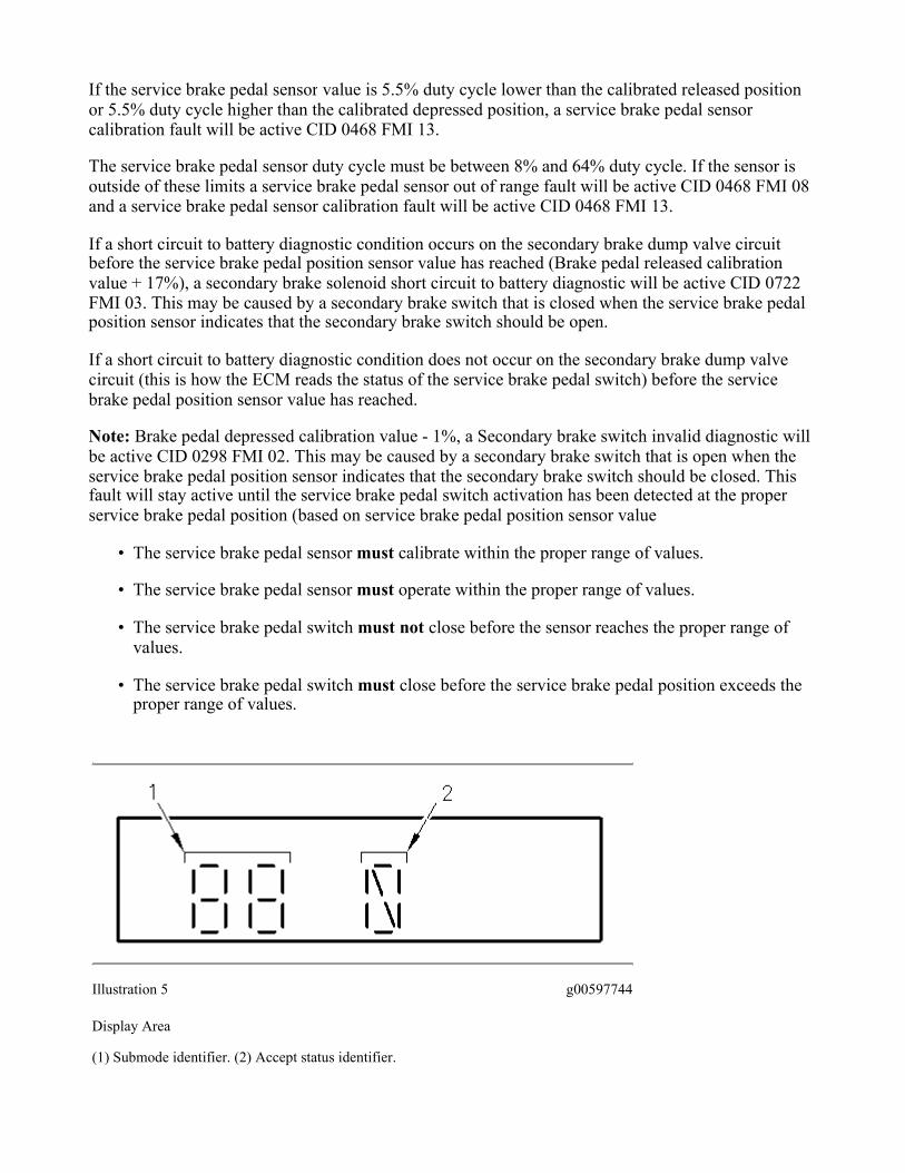
Illustration 5 g00597744
Display Area
(1) Submode identifier. (2) Accept status identifier.

Illustration 6 g00597745
Symbols that are shown on the accept status identifier
(3) Accepted Symbol. (4) Accepted symbol. (5) Not accepted symbol. (6) Not accepted symbol.
Submode
Calibration ParameterDescription
DataService Brake PedalCalibration Limits
12 Brake pedal released position
Right side = %Duty CycleLeft side = submode
10 % < Released < 34 %
13 Brake pedal depressed position
Right side = %Duty CycleLeft side = submode
39 % < Depressed < 63 %
Brake pedal travel range
Depressed -Released = Range(change in dutycycle)
21 % < Range < 37 %
Brake pedal switch range (switchmust inside this range)
Releases position + 16 % < SW closure <Depressed - 1 %
Table 4
Using the 4C-8195 Control Service Tool , enter the steering/braking calibration mode. Then,enter submode 12.
1.
Depress the service brake pedal completely. Release the service brake pedal slowly.2.
While the service brake pedal is released, press the clear switch to the DECREMENT (-)position in order to store the calibration value for the RELEASED position. When the switch ispressed, the accept status identifier (2) will briefly show the accepted symbol (4) or the notaccepted symbol (6) . Observe the accept status identifier (2) when the switch is pressed.
3.

Expected Result: The accepted Symbol (4) or the not accepted symbol (6) shows on the acceptstatus identifier (2) .
Results:
The accepted symbol (4) was showing. Proceed to Test Step 4. ◦
The not accepted symbol (6) was showing. Check that the service brake pedal iscompletely released. Repeat step 4. If not accepted symbol (6) is shown or if a CID 0468FMI 08 diagnostic code is present, use the component data display mode in order tocheck the range of the service brake pedal position sensor.
◦
Press the scroll switch in order to enter submode 13.4.
Depress the service brake pedal completely by using normal effort to hold the pedal in thedepressed position. Do not press hard on the pedal. While the pedal is held in the depressedposition, press the clear switch to the DECREMENT (-) position in order to store the calibrationvalue for the DEPRESSED position. When the switch is depressed, the accept status identifier(2) will briefly show accepted symbol (4) or not accepted symbol (6) . Observe the accept statusidentifier (2) when the switch is pressed.
5.
Expected Result: The accepted symbol (4) or the not accepted symbol (6) shows on the acceptstatus identifier.
Results:
The accepted symbol "4" was showing. The calibration of the inching pedal is complete.Exit the service brake pedal calibration mode by using the scroll switch. The mode switchcan also be used to exit the calibration.
◦
The not accepted symbol "6" was showing. Determine if the service brake pedal iscompletely depressed. Repeat step 5. If not accepted symbol "6" is shown or if a CID0468 FMI 08 diagnostic code is present, use the component data display mode in order tocheck the service brake pedal sensor.
◦
Submode 20 - Set Forward High Speed Lockout
This submode sets the highest speed that is obtainable when the machine is in forward.
Note: The transmission calibration mode for the D5M, D6M, D6R, and the D7R is mode number 6.The mode for the D6R Series II, D7R Series II, and the D8R Series II is mode number 7.
Procedure
With the 4C-8195 Control Service Tool , enter transmission calibration mode. Then, entersubmode 20.
1.
Use the INCREMENT (+) position and the DECREMENT (-) position of the clear switch toselect the desired maximum speed (F2 or F3).
2.

Exit submode 20 by scrolling to the next submode with the scroll switch. The mode switch canalso be used to exit the calibration.
3.
Submode 21 - Set Reverse High Speed Lockout
This submode sets the highest speed that is obtainable when the machine is in reverse.
Note: The transmission calibration mode for the D5M, D6M, D6R, and the D7R is mode number 6.The mode for the D6R Series II, D7R Series II, and the D8R Series II is mode number 7.
Procedure
With the 4C-8195 Control Service Tool , enter transmission calibration mode. Then, entersubmode 21.
1.
Use the INCREMENT (+) position and the DECREMENT (-) position of the clear switch toselect the desired maximum speed (R2 or R3).
2.
Exit submode 21 by scrolling to the next submode with the scroll switch. The mode switch canalso be used to exit the calibration.
3.
Submode 22 - Transmission Direction Lever Position SensorCalibration
This submode sets the NEUTRAL position for the position sensor of the transmission directioncontrol lever. The ECM monitors the sensor signal as the lever is moved in and out of neutral at leastfour times. When three dashes are showing in the display area, the calibration is complete. A flashingletter will normally be displayed. The procedure should be performed when the sensor has beenreplaced.
During this calibration, error codes ("EXX") can occur. The error codes appear in the display area ifthere is a problem with the conditions for the calibration or if there is a problem with the results of thecalibration. The error codes that can appear are listed below:
E02 - The engine speed is not zero.
E03 - The sensor calibration is faulty.
Exit the transmission calibration mode.1.
Return to the transmission calibration mode and repeat the procedure.2.
If the error code is still present, replace the sensor.3.
Exit the transmission calibration mode.4.
Return to the transmission calibration mode and repeat the procedure.5.
If the error code is still present, replace the detent assembly.6.

Exit the transmission calibration mode.7.
Return to the transmission calibration mode and repeat the procedure.8.
E08 - The diagnostic code CID 0299 is active. Correct the problem.
E09 - The machine speed is not zero.
Procedure
Note: The steps for this procedure must be performed exactly. The steps must be performed insequence. This procedure can terminate if any unexpected functions are activated or if a diagnosticcode is present. Do not change any switch positions. Do not move any levers. Do not depress anypedals. If there is a problem with the conditions for the calibration or if there is a problem with theresults of the calibration, an error code ("EXX") will appear in the display area.
Place the transmission direction control lever in the NEUTRAL position.1.
With the 4C-8195 Control Service Tool , enter transmission calibration mode. Then, entersubmode 22.
2.
Watch the display area of the Caterpillar monitoring system. The letter "F" should be flashing.Move the lever to the FORWARD position. The lever might need to be returned to theNEUTRAL position and the FORWARD position several times in order to stop the letter "F"from flashing.
3.
Note: If the conditions for setup are not correct, the flashing letter "F" is not shown in thedisplay area. An error code ("EXX") will appear. The calibration will not run until all necessaryconditions are met or error codes are corrected. Correct the error code and restart theseprocedures.
Now, the letter "N" should be flashing. Move the lever to the NEUTRAL position. The levermay need to be returned to the FORWARD position and the NEUTRAL position several timesin order to stop the flashing letter "N".
4.
Now, the letter "R" should be flashing. Move the lever to the REVERSE position. The levermay need to be returned to the NEUTRAL position and REVERSE position several times inorder to stop the flashing letter "R".
5.
Continue moving the lever to the position that matches the flashing letter. When the displayarea shows three dashes, the calibration is complete.
6.
Exit submode 22 by scrolling to the next submode with the scroll switch. The mode switch canalso be used to exit the calibration.
7.
Submodes 31 to 35 and 40 - ECPC Clutch Calibrations
The power train ECM includes two calibration procedures for the transmission clutches on machinesthat have electronic clutch pressure control (ECPC).

The clutch engagement pressure calibration sets the electrical current of each clutch solenoid inorder to obtain the correct pressure of each transmission clutch.
•
The clutch fill calibration sets the parameters for the transmission clutch fill. This calibrationwill affect the quality of the shifting of the transmission.
•
The transmission system needs to be calibrated if any of the following events have occurred:
A clutch solenoid valve has been replaced.•
A clutch solenoid valve has been substituted.•
A clutch solenoid valve has been cleaned.•
A different power train ECM has been installed.•
A transmission clutch has been rebuilt.•
Shifting is harsh.•
When the calibrations are performed for machines that have the ECPC, error codes ("EXX") canoccur. The error codes appear in the display area if there is a problem with the conditions or if there isa problem with the results of the calibration. The possible error codes are listed within each of thefollowing procedures.
Submode 31 - Clutch 1 Engagement; Submode 32 - Clutch 2 Engagement;Submode 33 - Clutch 3 Engagement; Submode 34 - Clutch 4 Engagement;Submode 35 - Clutch 5 Engagement
Engagement Pressure Specifications For Transmission Clutches
Sales ModelClutch 1 -Reverse
Clutch 2 -Forward
Clutch 3 -3rd Gear
Clutch 4 -2nd Gear
Clutch 5 -1st Gear
D5M PSTC (1)
2205 kPa(320 psi)
2415 kPa (350psi)
2550 kPa(370 psi)
2550 kPa(370 psi)
2480 kPa(360 psi)
D5N PSTC2205 kPa
(320 psi)2415 kPa (350
psi)2550 kPa
(370 psi)2550 kPa
(370 psi)2480 kPa
(360 psi)
D6M PSTC2205 kPa
(320 psi)2205 kPa (320
psi)2690 kPa
(390 psi)2690 kPa
(390 psi)2415 kPa
(350 psi)
D6N PSTC2344 kPa
(340 psi)2413 kPa (350
psi)2690 kPa
(390 psi)2690 kPa
(390 psi)2415 kPa
(350 psi)
Table 5
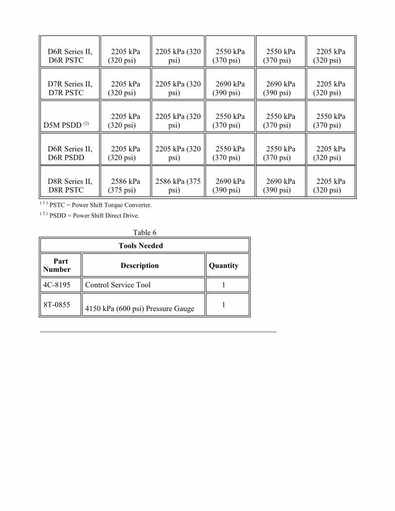
D6R Series II,D6R PSTC
2205 kPa(320 psi)
2205 kPa (320psi)
2550 kPa(370 psi)
2550 kPa(370 psi)
2205 kPa(320 psi)
D7R Series II,D7R PSTC
2205 kPa(320 psi)
2205 kPa (320psi)
2690 kPa(390 psi)
2690 kPa(390 psi)
2205 kPa(320 psi)
D5M PSDD (2)
2205 kPa(320 psi)
2205 kPa (320psi)
2550 kPa(370 psi)
2550 kPa(370 psi)
2550 kPa(370 psi)
D6R Series II,D6R PSDD
2205 kPa(320 psi)
2205 kPa (320psi)
2550 kPa(370 psi)
2550 kPa(370 psi)
2205 kPa(320 psi)
D8R Series II,D8R PSTC
2586 kPa(375 psi)
2586 kPa (375psi)
2690 kPa(390 psi)
2690 kPa(390 psi)
2205 kPa(320 psi)
( 1 ) PSTC = Power Shift Torque Converter.( 2 ) PSDD = Power Shift Direct Drive.
Tools Needed
PartNumber Description Quantity
4C-8195 Control Service Tool 1
8T-0855 4150 kPa (600 psi) Pressure Gauge 1
Table 6

Illustration 7 g00859862
Identification of the Solenoid Valves for Clutches on the machines that have the ECPC
The life of the transmission is affected when the pressure for clutch engagement is correct. Thesesubmodes set the pressure for the engagement of each clutch. The mechanic must adjust the electricalcurrent that is sent to each clutch solenoid valve in order to obtain the specified pressure for theengagement of the clutch. This calibration should be performed prior to performing the "clutch fillcalibration" (submode 40).
During this calibration, error codes ("EXX") can occur. The error codes appear in the display area ifthere is a problem with the calibration or if there is a problem with the results of the calibration. Theerror codes that can appear are listed below:
E01 - There is a problem with the active clutch solenoid or the speed sensor.

E04 - The transmission direction control lever is not in neutral.
E05 - The transmission oil temperature is below the threshold of 40 °C (104 °F) or there is a problemwith the transmission oil temperature sensor.
E06 - The engine speed is below the threshold of 1500 rpm.
E07 - The parking brake is not on.
E08 - CID 0299(sensor) is active. Correct the problem.
E09 - The machine speed is not zero.
E10 - The service brake pedal is pressed.
Procedure
Note: The steps of this procedure must be performed exactly. The Steps of this procedure must beperformed in sequence. This procedure can terminate if any unexpected functions are activated or if adiagnostic code is present. Do not change any switch positions. Do not move any levers. Do notdepress any pedals. If there is a problem with the calibration or if there is a problem with the results ofthe calibration, an error code ("EXX") will appear in the display area.
If a new clutch solenoid valve was installed, shift the transmission at least 12 times into a gearthat uses the solenoid valve. Allow sufficient time for the corresponding clutch to be fullypressurized.
1.
Warm the transmission oil to at least 40 °C (104 °F). The component data display mode (Modenumber 7) can be used to monitor the temperature of the transmission oil. The CID number is0177.
2.
Place a pressure gauge on the clutch that needs to be calibrated. A gauge that can measure 3500kPa (508 psi) is desired.
3.
Place the transmission direction control lever in the NEUTRAL position.4.
Place the parking brake switch in the ON position. The transmission will shift to NEUTRAL.5.
Set the engine speed to high idle.6.
With the 4C-8195 Control Service Tool , enter "Transmission Calibration Mode" (Mode 6) forthe D5M, D6M, D6R and the D7R. The mode for the D6R Series II, D7R Series II, and theD8R Series II is mode number 7. Then, enter the submode that corresponds to the clutch that isbeing calibrated.
7.
Submode 31 - Clutch 1 Engagement ◦
Submode 32 - Clutch 2 Engagement ◦
Submode 33 - Clutch 3 Engagement◦
Submode 34 - Clutch 4 Engagement ◦

Submode 35 - Clutch 5 Engagement◦
If all the conditions are correct for calibration, the specified pressure for the engagement for theparticular clutch is shown in the display area. The value that is shown is in units of ten kPa. Forthe actual value, multiply the value that is showing by 10. Record the value. In the remainingSteps, adjustments are made so that the pressure is the actual reading for pressure from thepressure gauge. The pressure that is specified in the procedure is also listed in the engagementpressure specifications table.
8.
Note: If the conditions for setup are not correct, the pressure is not shown in the display area.An error code ("EXX") appears instead of the pressure value. The calibration will not run untilall error codes are corrected. Correct the error code and restart these procedures.
When the pressure is showing on the display, move the transmission direction control lever tothe FORWARD position. This pressurizes the clutch that is being calibrated.
9.
The display will change. Now, the display shows a number that corresponds to the electricalcurrent of the particular solenoid valve. The INCREMENT (+) position and the DECREMENT(-) position of the clear switch can now be used to adjust the electrical current of the solenoidvalve. The solenoid valve controls the pressure of the engagement of the clutch.
10.
While the pressure gauge is monitored, use the clear switch in order to adjust the pressure.Adjust the pressure until the value that is on the pressure gauge matches the pressure that wasspecified in Step 8.
Move the transmission direction control lever to the NEUTRAL position. The calibration iscomplete.
11.
Use the scroll switch to go to the submode that corresponds to the next clutch that needs to becalibrated. The scroll switch may also be used to go to the "Clutch Fill Calibration" ( submode40). To exit transmission calibration mode, use the mode switch.
12.
Submode 40 - Clutch Fill
Tools Needed
PartNumber
Description Quantity
4C-8195 Control Service Tool 1
Table 7
The quality of the shifting of the transmission can be affected by the calibration of the clutch fill. Thecalibration procedure is automatic. The clutch engagement calibration (submodes 31 through 35)should be performed prior to performing the clutch fill calibration.
During this calibration, error codes ("EXX") can occur. The error codes appear in the display area ifthere is a problem with the calibration or if there is a problem with the results of the calibration. Theerror codes that can appear are listed below:
E01 - There is a problem with an active clutch solenoid or a speed sensor.
E04 - The transmission direction control lever is not in neutral.
E05 - The transmission oil temperature is below the threshold of 68 °C (154 °F) or the transmissionoil temperature sensor is faulty.
E06 - The engine speed is below the threshold of 1500 rpm.
E07 - The parking brake is not on.
E08 - CID 0299 (sensor) is active. Correct the problem.
E09 - The machine speed is not zero.
E10 - The service brake pedal is pressed.
E21 - Clutch 1 is at A limit.
E22 - Clutch 2 is at A limit.
E23 - Clutch 3 is at A limit.
E24 - Clutch 4 is at A limit.
E25 - Clutch 5 is at A limit.
For error codes E21, E22, E23, E24, or E25 the calibration software will select values that do the bestjob possible, but the error indicates something is wrong with either the calibration conditions or thecontrol system. Things to check for E21 through E25 are:
The oil and the transmission is fully warmed for the calibration.•
The valves are correctly torqued when the machine is cool.•
The seals are not worn.•
The clutch is not worn beyond the allowable range.•
The valve is not damaged.•
If a new valve was installed, shift the tractor into a gear that uses the new valve at least 12 timesbefore beginning the procedure.
•
Check that the priority valve solenoid is off.•
Once problems are fixed, run the clutch fill calibration (submode 40) again.
Procedure
Note: The steps of this procedure must be performed exactly. The Steps of this procedure must beperformed in sequence. This procedure can terminate if any unexpected functions are activated or if adiagnostic code is present. Do not change any switch positions. Do not move any levers. Do notdepress any pedals. If there is a problem with the calibration or if there is a problem with the results ofthe calibration, an error code ("EXX") will appear in the display area.

The clutch engagement calibration (submodes 31 through 35) should be performed prior toperforming the clutch fill calibration.
1.
If a new clutch solenoid valve was installed, shift the transmission at least 12 times into a gearthat uses the solenoid valve. Allow sufficient time for the corresponding clutch to be fullypressurized.
2.
Warm the transmission oil to at least 68 °C (154 °F). The component data display mode can beused to monitor the temperature of the transmission oil. The mode for the D6R Series II, D7RSeries II, and the D8R Series II is mode number 8. The mode for the D5M, D6M, D6R, and theD7R is mode number 7. The CID number is 0177. Operate the machine or allow thetransmission to spin in NEUTRAL in order to ensure that the transmission is fully warmed.
3.
Place the transmission direction control lever in the NEUTRAL position.4.
Place the parking brake switch in the ON position. The transmission will shift to NEUTRALand to first speed.
5.
On machines that have the power shift torque converter, set the engine speed to 1600 rpm. Ifthe calibration fails at 1600 rpm, recalibrate with the engine at 2000 rpm. On machines thathave the power shift direct drive, set the engine speed to 2000 rpm.
6.
With the 4C-8195 Control Service Tool , enter the transmission calibration mode (Mode 6).Then, enter submode 40.
7.
If all the conditions are correct for calibration, "0's" will move across the display area.8.
Note: If the conditions for setup are not correct, "0's" are not shown in the display area. Anerror code ("EXX") appears. The calibration will not run until all error codes are corrected.Correct the error code and restart the procedures.
When "0's" are moving across the display, move the transmission direction control lever to theFORWARD position. The clutch fill calibration will begin.
9.
The display changes. The display now shows the number of the active clutch (1 through 5). Thecalibration automatically changes in order to perform the calibration for each clutch.
10.
Note: During the calibration, there are many clutch fills occurring. Remain seated. Vibrationand noise will be present . If any of the conditions for setup are not followed during thecalibration, then the calibration will be stopped and a corresponding error code ("EXX") will beshown. Correct the error code and restart the procedures.
When the calibration is completed successfully, "---" will be shown on the display. An errorcode may also be displayed. The error code indicates that the calibration had a problem.
11.
Operate the machine in order to check the quality of the shifting of the transmission.12.
Exit submode 40 by scrolling to another submode with the scroll switch. The mode switch canalso be used to exit the calibration.
13.